The Pennsylvania State University The Graduate School Department of Mechanical and Nuclear Engineering
|
|
|
- Frederica Glenn
- 6 years ago
- Views:
Transcription
1 The Pennsylvania State University The Graduate School Department of Mechanical and Nuclear Engineering COUPLED FLUIDIC VIBRATION ISOLATORS FOR ROTORCRAFT PITCH LINK LOADS REDUCTION A Thesis in Mechanical Engineering by Nicolas A. Kurczewski c 2012 Nicolas A. Kurczewski Submitted in Partial Fulfillment of the Requirements for the Degree of Master of Science May 2012
2 The thesis of Nicolas A. Kurczewski was reviewed and approved by the following: Chris D. Rahn Professor of Mechanical Engineering Thesis Co-Advisor Edward C. Smith Professor of Aerospace Engineering, VLRCOE Director Thesis Co-Advisor Qian Wang Professor of Mechanical Engineering Karen A. Thole Professor of Mechanical Engineering Head of the Department of Mechanical Engineering Signatures are on file in the Graduate School. ii
3 Abstract Replacing rigid pitch links on rotorcraft with coupled fluidic devices has the potential to reduce the aerodynamic blade loads transmitted from the blade root to the swashplate. An analytical model of two coupled fluidic isolators is derived and experimentally validated for even and odd harmonic pitch link loads. The system consists of two elastomeric pumpers with fluid chambers that are coupled by an inertia track. This passive fluidic device can be tuned to reduce the transmitted force at a particular odd harmonic of the rotor speed by tailoring the fluid inertance in the inertia track. Benchtop experimental results agree with theory, demonstrating a reduction in odd harmonic pitch link loads of up to 90% compared to the system without fluid. The coupled fluidic isolators also significantly reduce transmitted loads relative to a rigid pitch link over a wide frequency range. Simulation of a UH-60 Blackhawk retrofit example shows potential for targeted odd harmonic excitation loads reduction up to 94% for multiple frequencies without affecting the even harmonic excitation response. iii
4 Table of Contents List of Figures List of Tables List of Symbols Acknowledgments vi viii ix xi Chapter 1 Introduction Introduction to Rotrocraft Pitch Links Related Research Research Objectives Chapter 2 Analytical Model System Model Governing Equations Force Frequency Response Function Chapter 3 Experimental Setup and Results Experimental Setup Odd Harmonic Excitations Even Harmonic Excitations Discrepancies Between Theory and Experiment Chapter 4 Discussion of Results Loads Reduction iv
5 4.2 UH-60 Retrofit Example Chapter 5 Conclusion 23 Appendix A Literature Review 24 A.1 Vibration Loads Control A.1.1 Passive Vibration Control A.1.2 Semi-Active Vibration Control A.1.3 Active Vibration Control A.2 Rotorcraft Vibration A.3 Fluidic Technology A.4 Fluidic Research for Rotorcraft Loads Control Appendix B Supplementary Analytical and Experimental Information 40 B.1 System Loading Harmonics B.2 Experimental Setup B.3 Experimental DAQ and Results B.4 Geometric Comparison B.5 Sensitivity Analysis Appendix C Experiment Part Drawings 52 C.1 Isolator Part Drawings C.2 Support Structure Part Drawings Appendix D Program Scripts 60 D.1 Labview DAQ Script D.2 Theoretical/Experimental Comparison Matlab Script D.3 UH-60 Example Theoretical Response Matlab Script Bibliography 70 v
6 List of Figures 1.1 Main rotor hub components Diagram of the coupled pitch link system Experimental setup and isolator assembly diagram Experimental odd harmonic frequency response results Experimental even harmonic frequency response results Theoretical odd harmonic frequency response results for the UH-60 system 22 A.1 Conventional passive isolator system A.2 Passive isolator frequency response plot A.3 Skyhook damper and partially active system A.4 Mechanical equivalent of the Smart Spring device A.5 Bell Model 427 LIVE c Isolator A.6 Mechanical equivalent of the LIVE c Isolator A.7 Mechanical equivalent of the LORD lead-lag damper with in-series spring 36 A.8 Single fluidic pitch link system A.9 Mechanical equivalent of the single fluidic pitch link system A.10 Harmonic load magnitudes for UH-60A A.11 Harmonic fluidic pitch link loads A.12 Blade tip torsional rotation B.1 Coupled fluidic pitch link system harmonic excitations B.2 Comparison of the rotor hub components to the experimental setup.. 42 B.3 Side view of assembled fluidic isolator B.4 Bottom view of assembled fluidic isolator B.5 DAQ comparison of odd harmonic FRF results B.6 Geometric comparison of the approximated UH-60 rigid pitch link to the necessary fluidic replacement B.7 Section view of the UH-60 retrofit fluidic pitch link B.8 Sensitivity of the undamped isolation frequency with respect to the fluidic element diameters (i.e. tuning port and piston) vi
7 C.1 Dimensioned drawing of the isolator housing C.2 Dimensioned drawing of the retaining washer C.3 Dimensioned drawing of the elastomeric diaphragm C.4 Dimensioned drawing of the prime mass C.5 Dimensioned drawing of the isolator housing support C.6 Dimensioned drawing of the support spacer D.1 Labview block diagram for collecting frequency response data vii
8 List of Tables 3.1 Experiment parameters Differences between the theoretical and experimental frequency response Theoretical and experimental loads reduction performance of a m fluidic inertia track for 3.5 Hz 1/rev excitation frequency Model parameters for a UH-60 retrofit example UH-60 theoretical load reduction for coupled fluidic pitch links with a m inertia track compared to the baseline rigid pitch link system.. 21 viii
9 List of Symbols A b = Base (piston) area, p. 5 A t = Tuning port area, p. 5 C = Elastomer damping constant, p. 5 f = Frequency, p. 18 F in,i = Input force (i=1,2), p. 5 F out,i = Output force (i=1,2), p. 5 I p = Inertance, p. 7 j = Imaginary unit, p. 8 K d = Pitch link stiffness, p. 5 K 0 = Rotor hub stiffness, p. 20 L = Inertia track length, p. 7 m b = Prime mass, p. 5 ρ = Fluid density, p. 7 P i = Pressure (i=1,..4), p. 5 Q = Flow rate, p. 5 R p = Pipe resistance, p. 7 R o = Orifice resistance, p. 5 s = Laplace domain variable, p. 8 ω = Angular frequency, p. 8 ix
10 Ω = Normalized harmonic frequency, p. 18 x i = Prime mass displacement (i=1,2), p. 5 ζ = Damping ratio, p. 8 x
11 Acknowledgments I want to express my gratitude to the many people who have helped me complete this thesis. I am extremely grateful to Dr. Chris D. Rahn for being an excellent advisor and guiding me through my research at The Pennsylvania State University. His advice and encouragement, in addition to great insight, provided me with the valuable support that I needed to complete this study. I would also like to thank my co-advisor Dr. Edward C. Smith for providing me the opportunity to work on such a valuable project, and for his knowledge and experience that allowed me to overcome many obstacles along the way. I had the pleasure of working with many students in the Mechatronics Research Laboratory and the Vertical Lift Research Center of Excellence. I would like to thank Lloyd Scarborough for his suggestions and comments that helped me with the experimental setup and analytical model. Lastly, I would like to express my gratitude to The Pennsylvania State University Vertical Lift Research Center of Excellence, The Applied Research Laboratory (ARL) at The Pennsylvania State University, and LORD Corporation for providing technical and financial support. xi
12 Dedication This thesis is dedicated to my family and friends, from whom I received unfaltering support toward the pursuit of my goals, and without whom a great number of my accomplishments would not have been possible. xii
13 Chapter 1 Introduction 1.1 Introduction to Rotrocraft Pitch Links The aerodynamic loads on helicopter rotor blades cause significant unsteady forces that are transmitted through the blade root and pitch link to the swashplate. The pitch link provides a rigid connection between the swashplate and the blade root to control the pitch of the blade about the azimuth (see Fig. 1.1). Pitch link loads increase exponentially with rotor power [1], justifying the need for loads reduction in new or retrofitted rotorcraft with larger engines for higher altitude flight and heavier payloads. Due to a constant rotor speed, excitation loads are harmonic and occur at integer multiples of the constant main rotor speed (1/rev, 2/rev, etc.). The primary function of the pitch link is to pass the 1/rev inputs from the swashplate. The higher harmonic loads, however, beat on the swashplate and drive hydraulics, causing fatigue and potentially premature failure. A coupled fluidic pitch link system has the potential to attenuate vibration loads such that blade pitch control components (e.g. swashplate and blade root) can achieve longer fatigue life, increase flight safety, and be designed

14 2 with reduced mass. The use of load controlling pitch links may also provide increased maximum forward velocity, payload, and altitude, which are currently limited by high loads due to retreating blade stall. Figure 1.1. Main rotor hub components [2]. 1.2 Related Research Active and semi-active pitch link systems have been developed by previous researchers, including the active hydraulic pitch links of ZF [3], pitch link load studies and active control [4], cyclical blade root stiffness variations designed to reduce blade vibration induced hub loads [5], and the semi-active Smart Spring device [6, 7]. In ap-
15 3 plications where tonal rather than broad band excitations are dominant, passive fluidic devices can be used for vibration and loads control. Redinger, for example, developed a fluidlastic mount for the main rotor pylon that reduces load transmission to the fuselage [8]. Elastomers were developed for rotorcraft loads control and other applications including automotive products and helicopter lead-lag dampers [9, 10, 11, 12]. Han et al. [13] modeled and analyzed a single fluidic pitch link and coupled fluidic pitch links. Similar to systems presented in [14], the coupled fluidic pitch link system has the potential to provide higher harmonic loads reduction for increased performance, efficiency, and noise reduction. 1.3 Research Objectives This paper builds on [13] by theoretically and experimentally investigating the loads reduction capability of a coupled two pitch link fluidic system through modeling, frequency domain analysis, experimental design, and experimental validation of the theoretical results. Theoretical predictions for a retrofit of the UH-60 Blackhawk with coupled fluidic pitch links are provided. See Appendix A for additional information on vibration control, rotorcraft vibration, and fluidic devices.
16 Chapter 2 Analytical Model 2.1 System Model In this paper, we study two pitch links on opposite sides of the rotor that are coupled by an inertia track, as shown in Fig The model applies to rotors with an even number of blades, the most common configuration in practice. The harmonic blade loading means that the two pitch links see the same magnitude and in-phase forcing for even harmonics and 180 degree out-of-phase forcing for odd harmonics. The blade pitch inertia is represented by an equivalent mass, m b, and the aerodynamic loading on each blade is F (t). The two isolators are coupled by a fluid-filled tube with lumped inertance I p and resistance R p. Each isolator has a piston of area A b that is sealed and elastically restrained by an elastomer with stiffness K d and damping value C. The mass moves with displacement x(t) in response to F (t) and the pressure P (t) generated in the isolator induces incompressible fluid flow Q(t) through the orifice with resistance R o. In this section, the transfer function from the input torsional aerodynamic force at the blade root to the output force on the swashplate is derived. The incompressible fluid
17 5 assumption means that the even harmonic loads are transmitted directly through as if the pitch links are rigid. Thus, we assume that the loading is an odd harmonic so the force in the two pitch links are equal and opposite, Fig Governing Equations Summing the forces on the first prime mass gives m b ẍ 1 = F in,1 P 1 A b K d x 1 Cẋ 1, (2.1) where all parameters and variables are defined in the nomenclature. The mechanicalfluidic coupling equation is a function of the isolator base (i.e. piston) area and the velocity magnitude, Q = A b ẋ 1. (2.2) The pressure drop across the orifice P 1 P 2 = R o Q (2.3) is approximated with a linear relationship and has decreasing accuracy with increasing frequency. Summing the forces transmitted to ground yields the output force for Isolator 1, F out,1 = P 1 (A b A t ) + K d x 1 + Cẋ 1. (2.4)
18 6 Figure 2.1. Diagram of the coupled pitch link system.
19 7 The two fluidic pitch links are coupled together by the inertia track with a pressure drop that is a function of the fluid inertance, flow rate, and pipe flow resistance, P 2 P 3 = ρl Q A t + R p Q, (2.5) where the fluid inertance I p = ρl A t. For the second mass, m b ẍ 2 = F in,2 P 4 A b K d x 2 Cẋ 2, (2.6) where the external force is equal and opposite that of Isolator 1. The induced flow rate Q = A b ẋ 2. (2.7) The pressure drop across the orifice of Isolator 2 is P 3 P 4 = R o Q. (2.8) The transmitted load through Isolator 2 is F out,2 = P 4 (A b A t ) + K d x 2 + Cẋ 2. (2.9) Equations (2.1)-(2.9) can be solved for the nine unknowns: x 1, x 2, P 1, P 2, P 3, P 4, Q, F out,1, and F out,2.
20 8 2.3 Force Frequency Response Function Solving the Laplace Transformed Eqns. (2.1)-(2.9), the transfer function from the input force to output force for odd harmonic excitations is F out,1 (s) F in,1 (s) = F out,2(s) F in,2 (s) = K s2 + 2ζ z ω z s + ωz 2 s 2 + 2ζ p ω p s + ωp 2, (2.10) where the pole undamped natural frequency 2A t K d ω p = ρla 2 b + 2A, (2.11) tm b and damping ratio ζ p = AtA2 b (2Ro+Rp)+2AtC 2(ρLA 2 b +2Atm. The zero undamped natural frequency b)ω p 2A t K d ω z = ρla b (A b A t ), (2.12) and damping ratio ζ z = A ba t(a t A b )(2R o+r p) 2A tc 2A b ρl(a t A b )ω z. The pole frequency is a function of the prime mass, elastomer stiffness and area, and the fluid inertance. The zero frequency does not depend on m b, and thus is independent of the blade s pitch inertia. The pole and zero damping ratios depend on material properties and fluid dissipation. See Appendix B for additional information on system loading harmonics.

21 Chapter 3 Experimental Setup and Results 3.1 Experimental Setup Figure 3.1. Experimental setup and isolator assembly diagram.
22 10 The experimental setup and assembly diagram of the isolators used for the experiment are shown in Fig The aluminum test rig frame is designed to be substantially stiffer than the isolator assemblies. Two shakers independently drive the two isolators. The isolator housing and washer are fabricated by machining high-density polyethylene (HDPE) round stock. An elastomeric disk is clamped between these parts, providing the fluidic pitch link stiffness and sealing the fluid chamber. The diaphragm is supported by steel washers on both sides around the stinger attachment point to distribute the load from the shaker and to prevent tearing or bulging in the elastomer. A pipe fitting at the top of the isolator connects the inertia track to the isolator housing. Piezoelectric load cells measure the input force on the stinger and output force to the frame (i.e. ground/swashplate). The inertia track is made from reinforced high-pressure tygothane polyurethane tubing. A T-fitting and valve in the middle of the inertia track allow pressurization of the coupled isolator system to 35 kpa to prevent fluid cavitation. Filtered and deionized lowimpurity water is the working fluid. The prime masses are machined from high carbon steel round stock. Experimental frequency response tests are performed by supplying the shakers with 30-second chirp signals at a 10kHz sampling rate. Ten sets of FFT data are averaged for each experimental run to reduce noise. The experimental apparatus is mounted on a pneumatic isolation table to minimize external disturbances. The results are repeatable for low amplitude input (i.e. less than 4N p-p). Four experimental data sets are collected for both the odd and even harmonic cases and compared with theory. Data are collected for the baseline case (i.e. empty isolator
23 11 without fluid) and three different inertia track lengths. The parameter values for the experiment are provided in Tab. 3.1 and determined by measurement, calculation, or tuning to match theory and experiment. The prime masses are weighed and the inertia track lengths are measured. The tuning port and base areas are calculated from their measured respective diameters. The elastomer stiffness, elastomer damping constant, and the pipe and orifice resistances are tuning parameters. The baseline experimental response curve establishes the elastomeric damping constant. The orifice resistance is a constant that is set for all experimental cases and the pipe resistance is assumed to be a linear function of the tube length. 3.2 Odd Harmonic Excitations The experimental results for odd harmonic forcing involves driving the shakers with equal and opposite forces. The experimental and theoretical frequency response magnitudes and phases are compared in Fig The theoretical model closely matches the experimental results in the lower frequency range (2-12 Hz) and accurately predicts the location of the pole and zero. The theoretical and experimental phases (see inset) are also close. The results clearly show that fluidic pitch links can reduce high frequency loads to the swashplate. Relative to the baseline, the coupled fluidic pitch links transmit lower loads over the entire frequency range except the small region between 4 and 9 Hz. Relative to rigid pitch links with unity (0 db) frequency response, the reduction range is the entire range greater than 9 Hz. If the 1/rev frequency is less than 5 Hz, the coupled pitch links
24 12 Table 3.1. Experiment parameters. Constant Definition Value Units m b Prime Mass kg K d Link Stiffness N/m C Elastomer Damping N s/m A t Tuning Port Area m 2 A b Base (Piston) Area m 2 ρ Fluid Density kg/m 3 L 1 Inertia Track Length m L 2 Inertia Track Length m L 3 Inertia Track Length m R p Pipe Resistance L N s/m 5 R o Orifice Resistance N s/m 5 will not interfere with flight control because the output force is in-phase and close to the same magnitude as the input force in this frequency range. The results also show that as the inertia track length, and thus the fluid inertance, is increased, the pole and zero frequencies decrease.
25 13 Figure 3.2. Odd harmonic frequency response results, theoretical (solid) and experimental (dotted), for varying inertia track length: baseline (black), m inertia track (red), m inertia track (blue), and m inertia track (yellow).
26 Even Harmonic Excitations The theoretical even harmonic response is compared to the experimental data in Fig The experimental results show that the frequency response function magnitude is not exactly the theoretically predicted value of one for an incompressible fluid. The experimental force transfer function is approximately unity, however, and does not clearly exhibit a pole or zero in the frequency range shown. 3.4 Discrepancies Between Theory and Experiment Discrepancies between the theoretical and experimental frequency response can be explained by the errors in the vibration shaker input phase, fluidic system compliance, and test frame dynamics. Although the shakers are not identical, the input voltages are tuned so that the input forces have the desired (equal) magnitude and phase (0 or 180 ). Small variations in input phase and magnitude contaminate the experimental response. Unmodeled dynamics associated with compliance in the inertia track tubing, isolator housing, and elastomeric diaphragm produce the experimentally observed response in the Hz frequency range in all of the data sets. The discrepancies between theory and experiment are tabulated in Tab. 3.2 as percentages for the region of interest (0-15 Hz) using L = max( data model model ) and L 2 Σ = n(data model) 2 n error norms. The error for the odd harmonic cases is significantly lower than that of the even harmonic cases because the unmodeled dynamics dominate the even responses. The model for the odd harmonic excitations is accurate to within 10% by the L error norm or 4% by the L 2 error norm.
27 15 Figure 3.3. Even harmonic frequency response results, theoretical (solid) and experimental (dotted), for varying inertia track length: baseline (black), m inertia track (red), m inertia track (blue), and m inertia track (yellow).
28 16 Table 3.2. Differences between the theoretical and experimental frequency response. Harmonic Inertia Track [m] L [ % ] L 2 [ % ] Baseline Odd Even See Appendix B for additional information on the experimental setup and data acquisition; Appendix C for experiment part drawings; and Appendix D for the data acquisition and analysis program scripts.
29 Chapter 4 Discussion of Results 4.1 Loads Reduction The system under consideration achieves pitch link loads reduction at multiple frequencies. For example, if the rotor speed is 3.5 Hz, then the first six corresponding rotor harmonics are 3.5, 7.0, 10.5, 14.0, 17.5, and 21 Hz. Loads reduction performance of the m inertia track system is given in Tab. 4.1, with the amplification value at each harmonic taken from the appropriate response curve, even or odd, compared as percent reduction from both the baseline empty pitch link and an infinitely rigid pitch link (0 db). The results show little amplification of the 1/rev harmonic force, which is desirable because 1/rev is the cyclic pitch input from the pilot. Amplitude reduction occurs for the subsequent five normalized harmonic frequencies of the system (i.e. frequencies of vibratory aerodynamic loads).
30 18 Table 4.1. Theoretical and experimental loads reduction performance of a m fluidic inertia track for 3.5 Hz 1/rev excitation frequency. % Reduction Harmonic Fluidic Rigid Ω f [Hz] Curve Theory Experiment Theory odd even odd even odd even
31 UH-60 Retrofit Example A potential retrofit example is shown by applying the coupled fluidic isolator system to the UH-60 Blackhawk helicopter to demonstrate the tuning capability and potential for loads reduction. While the coupled pitch link system has only been designed for a two-bladed rotor, the system can be applied to the UH-60 four-bladed rotor by coupling only pitch links on opposing sides of the rotor hub. To make the analysis more realistic, compliance of the rotor hub components is included to determine the baseline frequency response function, which appears in the equations as a spring between the blade inertia and isolator system. The introduction of another degree of freedom creates two pole frequency locations that are not the same as the system with an assumed rigid hub, but still has only one zero frequency located at the same frequency as in the previous analysis. The values used to calculate the theoretical response of the system are provided in Tab The chosen values of m b and K 0 correspond to the rigid-body blade pitch inertia and equivalent stiffness of the rotor hub, not including the pitch link stiffness, of a UH- 60 Blackhawk helicopter. These parameters are used to calculate the baseline frequency response. The fluidic pitch link stiffness, K d, is introduced in series with the rotor hub to determine the fluidic system response if the fluidic system is drained of fluid. Inertia track length is used to tune the zero frequency location of the coupled fluidic pitch links to eliminate the 3/rev (12.9 Hz) harmonic of the constant 258 RPM main rotor speed. A t and A b are physically realizable parameters for the geometric envelope of the pitch link. Figure 4.1 shows the theoretical frequency response for the baseline rigid system,
32 20 Table 4.2. Model parameters for a UH-60 retrofit example. Constant Definition Value Units m b Prime Mass kg K d Link Stiffness N/m K 0 Rotor Hub Stiffness N/m C Elastomer Damping N s/m A t Tuning Port Area m 2 A b Base (Piston) Area m 2 ρ Fluid Density kg/m 3 L Inertia Track Length m R p Pipe Resistance N s/m 5 R o Orifice Resistance N s/m 5 empty fluidic pitch link system, and coupled fluidic pitch link system to compare the magnitude of the transmitted force and determine the load reduction performance of the fluidic pitch link system over the rigid pitch link system. Significant advantages and tuning capability are achieved by using fluidic pitch links in place of the rigid pitch link system for controlling the magnitude of the response and the resonant frequency location. The percent load reduction for the first six main rotor harmonics is provided in Tab As expected, the third and fifth harmonic responses are reduced by the fluidic pitch
33 21 link. The addition of the rotor hub compliance changes the even harmonic excitation response relative to the baseline case as well because the fluid isolators lock or become infinitely rigid and the incompressible fluid does not flow. In this case, the effective stiffness of the system is the rotor hub stiffness and the response equals the baseline response. Theoretical load reduction, up to 94%, of the targeted 3/rev aerodynamic load and 5/rev loading is effectively achieved without amplification of the even harmonic excitations and minimal amplification of the 1/rev excitation. Table 4.3. UH-60 theoretical load reduction for coupled fluidic pitch links with a m inertia track compared to the baseline rigid pitch link system. Ω [/rev] f [Hz] % Reduction See Appendix D for the UH-60 analysis program script.
34 22 Figure 4.1. Theoretical odd harmonic frequency response results for the UH-60 system, baseline rigid pitch links (solid, black), coupled fluidic pitch links with no fluid (dashed, red), and coupled fluidic pitch links with m inertia track (dotted, green).
35 Chapter 5 Conclusion Replacing rigid pitch links on rotorcraft with coupled fluidic devices has the potential to reduce the aerodynamic blade loads transmitted from the blade root to the swashplate. An analytical model of two coupled fluidic isolators has been derived and experimentally validated for even and odd harmonic pitch link loads. This passive fluidic device can be tuned to reduce the transmitted force at a particular odd harmonic of the rotor speed by tailoring the fluid inertance in the inertia track. Benchtop experimental results agree with theory, within 4% by the L 2 error norm, demonstrating a reduction in odd harmonic pitch link loads of up to 90% compared to the system without fluid. The coupled fluidic isolators also significantly reduce transmitted loads relative to a rigid pitch link over a wide frequency range. Simulation of a UH-60 Blackhawk retrofit example shows potential for targeted odd harmonic excitation loads reduction up to 94% for multiple frequencies without affecting the even harmonic excitation response.
36 Appendix A Literature Review A.1 Vibration Loads Control There are many loads control methods which have been explored since the development of rotary wing aviation. These methods include active, passive, and semi-active systems, which were not fully understood by the mechanical engineering community until the introduction of vibration control theory into the technical curriculum around the middle of the 1930 s. The early focus of vibration control was for rotating machinery, using passive components to change system parameters to circumvent resonant situations; however, design guidelines for load control systems were vague and underdeveloped. The comprehension of damping was also in adolescent stages during this period and very little was understood about the many damping modes (e.g. coulombic, viscous, hysteretic, etc.). For these reasons, few vibration and loads control devices were available that could be evaluated using the early analytical models of linear vibrations. [9] The late 1950 s and early 1960 s gave rise to the study of random vibration for aeronautical applications (e.g. fatigue). This development led to the standardization of
37 25 random vibration analysis, the effects of which could be controlled by optimizing passive system properties such as mass, damping, and stiffness. Many new forms of vibration analysis and vibration control techniques subsequently followed, for instance the semiactive isolation Skyhook damper. Improvements in technology and manufacturing processes have led to increased equipment capability, such as actuators, sensors, and signal processing hardware that can be applied to a broad spectrum of vibration control applications. Vibration control systems fall into three categories: passive, active, or semi-active. [9] A.1.1 Passive Vibration Control Passive loads control is defined by the implementation of components such as springs, masses, and dampers which require no external intervention or feedback control to achieve the desired response. These systems are often simple, inexpensive, and require little maintenance throughout service life. Studies by [15, 16, 17] develop the transfer function between the input velocity and the output velocity of a suspended mass for ground vehicle systems that use passive components and the Wiener filter technique. The transfer functions are then used to minimize the weighted sum of mean square acceleration that is transmitted to the isolated mass. The conventional linear spring-mass-damper system for this technique [9] gives the transfer functions V V o = 2ζω ns + ωn 2 s 2 + 2ζω n s + ωn 2 (A.1)
38 26 and V F = s/m s 2 + 2ζω n s + ωn 2, (A.2) with system model and frequency response given in Fig. A.1 and Fig. A.2. Figure A.1. Conventional passive isolator system [9]. Equation A.1 and Fig. A.2 show that the single degree-of-freedom system frequency response is separated into two regions: for ω < ω n, the transfer function is initially equal to one and approaches the resonant peak, and for ω > ω n, the transfer function recedes from the resonant peak, entering the region of isolation when ω = 1.41 ω n. The effect of variable damping ratio on the response is given in Fig. A.2. The maximum relative response magnitude is inversely proportional to the amount of damping in the system (i.e. response magnitude decreases with increased damping). The optimized transfer function for isolation corresponding to Equation A.1 is
![27 Figure A.2. Passive isolator frequency response plot [9]. V V o = ω 2 n s 2 + 2ζω n s + ωn 2. (A.](/docs-images/75/72931506/images/39-0.jpg "3) The optimal system cannot be achieved through the use of passive elements alone.")
39 27 Figure A.2. Passive isolator frequency response plot [9]. V V o = ω 2 n s 2 + 2ζω n s + ωn 2. (A.3) The optimal system cannot be achieved through the use of passive elements alone. A solution to this problem is to use an almost passive system, also known as a semi-active system.
40 28 A.1.2 Semi-Active Vibration Control Semi-active loads control can be achieved through manipulating structural properties of the system such as mass, stiffness, and damping. While all of these components are passive, the active portion of the system comes from changing these properties through external intervention. Some sources refer to this as dynamic impedance control, to provide for categorization of semi-active systems. The actuation force is only used to change system properties to achieve the desired response, not to directly counteract the vibration force. By rearranging the passive suspended mass system [9], the damper can be moved such that its effect is proportional to the absolute velocity of the mass instead of the relative velocity between the mass and excitation. This configuration is known as the Skyhook damper system, given in Fig. A.3. Figure A.3. Skyhook damper and semi-active system [9].
41 29 These systems allow for greater flexibility and therefore greater control over the system response. The actuator force, F c, can be used to provide a response similar to that of a passive damper, and removed in frequency bands that are far away from the natural frequency to reduce the overall magnitude of the transfer function. The most important feature of the Skyhook damper and semi-active systems is the ability to control absolute velocity instead of relative velocity. Therefore, a semi-active system provides additional control over a passive system. A.1.3 Active Vibration Control Although more expensive and complex, active systems can provide even more control than passive systems. Many advances in active vibration isolation have occurred since the first attempts in the early 1900 s, summarized in the collections [10] and [18]. Some applications require large amounts of isolation to achieve adequate system performance. This is done by using the force F c, shown in Figure A.3, to resist natural motion, thereby using external energy to counteract the system s energy. The actuator force F c is proportional to the absolute velocity of the isolated mass to exploit the Skyhook damper system for conveniently controlling the systems related to Eqns. A.1 and A.3. Active vibration control systems are often avoided because they are complex, expensive, and have significant power requirements. Although there are many disadvantages, active systems are becoming more popular with the increasing demand for high performance.
42 30 A.2 Rotorcraft Vibration Rotorcraft vibration reduction and loads control have been a challenge since the beginning of vertical lift aviation. The aerodynamic loads on helicopter rotor blades cause significant unsteady forces that are transmitted through the blade root and pitch link to the swashplate. The main rotor operates at a constant rotational speed which causes harmonic aerodynamic blade loads that occur at integer multiples of this constant rotor speed (e.g. 1/rev, 2/rev, etc.). Such an example of this vibration is the leadlag vibration (i.e. motion in the plane perpendicular to the mast) which results from a sudden increase in drag loads (crossing the 0 azimuth angle) and a reduction in drag loads (crossing the 180 azimuth angle), where the azimuth angle is measured from the tail boom, or Coriolis forces associated with flapping. The lead-lag vibration mode contributes significantly to the overall vibration problem, as well as the rotational pitching mode of the blade. The flapping mode (i.e. motion in the plane parallel to the mast) is not as notable because of the high viscous damping associated with motion normal to the blade chord, and is exploited for flight control. A helicopter in steady-state forward flight will experience fuselage vibration that result from a combination of the blade passing frequency multiples (e.g. a four-bladed rotor will experience 4/rev, 8/rev, etc.) and the aerodynamic blade loads associated with the blade passing frequency and adjacent normalized frequencies (e.g. a seven-bladed rotor will experience 6/rev, 7/rev, and 8/rev). The constant flap angle (i.e. coning angle) is not of consideration because the constant loading is not related to the oscillatory aerodynamic blade loads. There are two requirements for the main rotor hub of the helicopter: to change the
43 31 geometric blade pitch as a function of azimuth angle and to accommodate the aerodynamic loads that cause flap and lead-lag blade motions. The component of interest for this study is the pitch link because the rigid pitch link achieves only the first of the aforementioned requirements. If the pitch link could also attenuate vibration loads, blade pitch control components (e.g. swashplate and blade root) would achieve longer fatigue life, increase flight safety, and could be designed with reduced mass. The use of load controlling pitch links may also increase maximum forward velocity, payload, and altitude, which are currently limited by high loads associated with retreating blade stall. The solutions for vibration loads control are separated into two groups: blade-based systems and hub-based systems. Unfortunately, blade-based systems increase blade mass and alter blade design, which causes undesirable changes in flight dynamics. An example of a blade-based system is the trailing edge flap. The design, actuation capabilities, and active control effects have been studied extensively by [19], with optimization techniques given by [20], and an investigation of closed-loop control for noise and load reduction provided by [21]. Testing of actively controlled trailing edge flaps to evaluate aerodynamics, acoustics, and dynamics was performed by [22], showing decreased aerodynamic vibration levels and increased fast-cruise performance. Some other techniques that have been considered include: cyclical blade root stiffness variations designed to reduce blade vibration induced hub loads, [5]; active trailing edges using electrically actuated piezoceramics to accomplish morphing cross-section of the trailing edge, [23]; and Individual Blade Control (IBC) methodology, which has been studied extensively to help minimize the individual blade load contribution through blade deformation techniques, [24]. Although these methods are effective, hub-based systems have received much more interest
44 32 from the rotorcraft community because the blades remain unchanged and existing helicopter designs can be retrofitted to increase performance, making pitch links a major focus of hub-based loads reduction, [25]. Many examples are available where rigid pitch links have been targeted for replacement by active and semi-active systems for loads control. Reducing vibration loads transmitted from the blade root to the swashplate can improve fatigue life of rotor components and reduce vibration transmitted to the fuselage. The most studied pitch link replacement is a semi-active piezoceramic actuator system, referred to as the Smart Spring device or Smart Hybrid Active Rotor Control System (SHARCS) [6, 7]. The SHARCS system uses the Smart Spring device in conjunction with active shape control technology to reduce vibration loads and noise by as much as 60% by controlling the damping and stiffness of the pitch link with large bandwidth piezoelectric materials. The Smart Spring system uses the piezoceramic actuator to change stiffness by engaging springs, modeled as a two degree-of-freedom system, given in Fig. A.4. The stiffness can vary between the value of the baseline spring stiffness (uncoupled) and the effective parallel spring stiffness (fully coupled) by adjusting the frictional force generated by the piezoceramic actuator. The effective coulombic damping can be calculated only when the system is between the uncoupled and fully coupled states. Experimental data is provided to validate the model, [6]. Potential problems with this device include: the need for power in the rotating frame transmitted by slip ring or other method; the potential flight instability caused by individual or multiple pitch link actuation failure; the maintenance and heat generation issues which arise through sliding mechanical interaction; and the lack of adaptability for

45 33 energy harvesting. These design and sustainability concerns will need to be addressed in future work; however, the premise of the technology does accomplish the objective. Figure A.4. Mechanical equivalent of the Smart Spring device [6]. Other studies have investigated the use of orifice dampers, electrorheological (ER) fluid, magnetorheological (MR) fluid, shape memory alloy (SMA) materials, variable stiffness elements, and hydraulic systems. Each have implementation complications due to mass, actuation method, serviceability, or reliability. A.3 Fluidic Technology Fluidic technology has been developed and successfully applied to many industrial and rotorcraft applications. Most of the systems use reservoir designs where fluid is pumped through an orifice and inertia track, between fluid reservoirs, as a result of external loading. The addition of fluid to the standard elastomeric device creates a zero in the system response, increasing tunability of dynamic response characteristics. The dynamics of the system use the input excitation to shear an elastomeric component (with
46 34 known stiffness) while pumping fluid between chambers, eliminating wear surfaces that are found in piston style pumping devices. Rotorcraft applications for this technology have been limited to fuselage isolators and blade lead-lag dampers. These applications demonstrate the diversity of the technology, applied for either energy dissipation (damping) or loads reduction (isolation), which can both be achieved by accelerating a small mass of fluid to high velocity. For rotorcraft vibration isolation the target frequencies are typically an integer multiple of the main rotor speed, expressed as N/rev, for which fluidic technology can provide up to 97% isolation of the input excitation, [12]. In 1999, Redinger [8] provided the design procedure and experimental validation of the LIVE c (i.e. Liquid Inertia Vibration Eliminator) Bell model 427 main rotor pylon mounting system, given in Fig. A.5. This system achieves approximately 94% isolation of the 4/rev vertical main rotor vibration, attained through the variable vertical stiffness of the pylon mount which has a high static stiffness and a much lower dynamic stiffness at 4/rev excitation. The system uses fluidic technology by exchanging fluid between two reservoirs that are pressurized to mitigate the possibility of cavitation. The inner cylindrical component is allowed to move axially, causing fluid to be pumped between reservoirs by means of an inertia track. The inertial force of this fluid motion, at discrete frequencies, attenuates the elastomeric spring force, causing the system to achieve isolation. The technical community still debates whether the softening effect described by [8] is the correct mechanical interpretation, or if the system demonstrates properties of increasing inertia which result in a similar analytical effect. The equivalent mechanical system for the LIVE c isolator is shown in Fig. A.6.
![35 Figure A.5. Bell Model 427 LIVE c Isolator [8]. Figure A.6. Mechanical equivalent of the LIVE c Isolator [8].](/docs-images/75/72931506/images/47-0.jpg "Similar to the LIVE c device, [11] describes a fluidic device that replaces elastomeric lead-lag dampers on the main rotor hub to control in-plane blade loads by providing increased")
47 35 Figure A.5. Bell Model 427 LIVE c Isolator [8]. Figure A.6. Mechanical equivalent of the LIVE c Isolator [8]. Similar to the LIVE c device, [11] describes a fluidic device that replaces elastomeric lead-lag dampers on the main rotor hub to control in-plane blade loads by providing increased loss factors in a small geometric envelope. These devices are designed for
48 36 minimum elastic stiffness and maximum loss factor without applying high loads on the blade root or generating excessive heat. To satisfy these design considerations, a pressure relief valve is typically used to alleviate high loading conditions present at the 1/rev operating frequency. The mechanical equivalent of this system is shown in Fig. A.7. The LORD lead-lag damper has proven effective in many applications, producing loss factors of up to 1.3. Figure A.7. Mechanical equivalent of the LORD lead-lag damper with in-series spring [11]. A.4 Fluidic Research for Rotorcraft Loads Control Analytical models by [13] show promise for loads control on the helicopter main rotor hub using fluidic pitch links. The investigation shows that isolation using single fluidic pitch links, Fig. A.8, can effectively reduce 4/rev excitation loads by up to 98.4%. Reducing any of the system harmonic loads will enlarge the operational flight envelope and increase the service life of rotor components, specifically the 2, 3, and 4/rev which contribute to approximately 1/3 of the total blade loading.


49 37 The mechanical equivalent for the single fluidic pitch link system is given in Fig. A.9. The zero frequency can be tuned such that a single discrete frequency can be isolated for load attenuation. Figure A.8. Single fluidic pitch link system [13]. Figure A.9. Mechanical equivalent of the single fluidic pitch link system [13].
50 38 The introduction of fluid inertia has several effects on the single pitch link system, such as decreasing the system natural frequency and increasing the transmissibility magnitude of harmonics not targeted by the imposed zero. The harmonic aerodynamic load magnitudes for the UH-60A helicopter during high speed forward flight and high altitude dynamic stall are provided in Fig. A.10. After including the fluid inertia, non-targeted harmonic loads increase, as shown by the aerodynamic model results in Fig. A.11, with reduction of the 4/rev and 5/rev loads and amplification of the 6/rev and 7/rev loads. Comparable results are given for the tip torsional rotation, Fig. A.12, [13]. The flight states have little effect on the fluidic isolator performance characteristics. This investigation builds on the single fluidic pitch link system [13] by theoretically and experimentally investigating the loads reduction capability of a coupled two pitch link fluidic system through modeling, frequency domain analysis, experimental design, and experimental validation of the theoretical results. Figure A.10. Harmonic load magnitudes for UH-60A [26].
51 39 Figure A.11. Harmonic fluidic pitch link loads [13]. Figure A.12. Blade tip torsional rotation [13].
52 Appendix B Supplementary Analytical and Experimental Information B.1 System Loading Harmonics An example based on a two-bladed rotor is used to demonstrate and establish the analytical model of the fluidic pitch link system, one pitch link corresponding to each blade. The system is used to develop the transfer function of the pitch link (i.e. the force frequency response function between the blade root and swashplate). The coupled pitch link system can be analyzed as two independent systems that describe the aerodynamic excitation harmonics, odd and even systems as shown in Fig. B.1. The odd harmonic system has vibration loading that is 180 o out-of-phase (i.e. the aerodynamic loading on the pitch links is equal and opposite), while the even harmonic system has vibration loading that is in-phase. The odd harmonic system creates a pressure difference between the fluid chambers of the fluidic pitch links, thereby generating fluid flow. The even harmonic system does not generate fluid flow because the pressure generated by the loading is equal in both chambers. The only frequencies of interest are the harmonics of the main

53 41 rotor speed. The discrete frequencies can be extracted from the continuous frequency response functions of the odd and even harmonic systems to sufficiently characterize all of the main harmonics for a two-bladed helicopter. Figure B.1. Coupled fluidic pitch link system harmonic excitations. B.2 Experimental Setup The experimental setup used to validate the analytical model can be compared directly to the physical system, Fig. B.2. The experimental fluidic isolators are fabricated in-house by machining HDPE stock. An assembled fluidic isolator, with stinger and load cell, is given in Fig. B.3 and B.4 to show the respective side and bottom views. The tuning port location for the isolator is chosen to be a convenient location for machining purposes, and does not necessarily indicate the required tuning port location for a production part.

54 Figure B.2. Comparison of the rotor hub components [2] to the experimental setup. 42

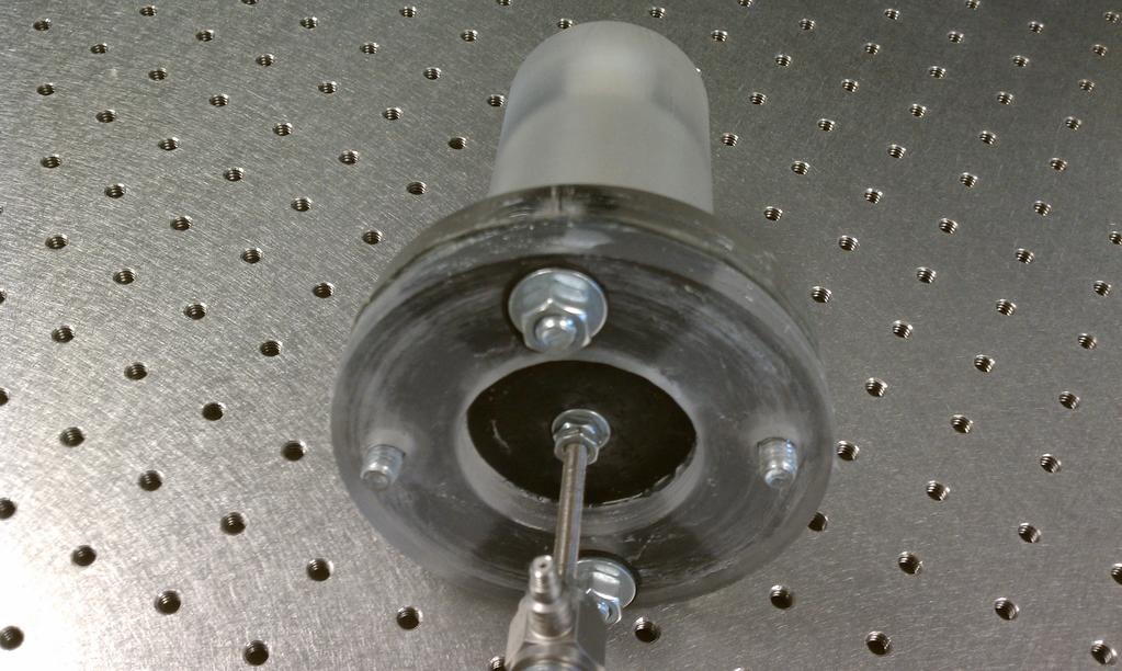
55 43 Figure B.3. Side view of assembled fluidic isolator. Figure B.4. Bottom view of assembled fluidic isolator.
56 44 B.3 Experimental DAQ and Results The initial data acquisition (DAQ) system used to obtain experimental data proved to be inadequate for capturing important frequency response features. The initial DAQ system (D-Space) was unable take a continuous set of data over the required time interval and frequency range. Because of limited memory capabilities, sections of data must be saved several times during each experimental run, resulting in a discontinuous time-history with gaps of null data at the save intervals. This caused difficulty in obtaining the frequency response function because a significant portion of the data was null and the variable length discontinuities created inaccurate FFT results. The frequency response function was obtained from custom digital signal processing that captures extrema during time intervals between predetermined save points for an incrementing excitation frequency. The resulting data with this complex setup was close to the theoretical model, but still contained significant error. The D-Space DAQ system was replaced with a more capable DAQ (National Instruments) that is able to perform a FFT on the collected data over the entire time interval and frequency range. The resulting data is more smooth and more accurate than the initial data from the D-Space DAQ because data is collected continuously, allowing for the use of a chirp signal instead of constant excitation frequencies. A comparison of the collected data from each DAQ system is given in Fig. B.5. The spectral resolution of the D-Space data is very coarse, because of the method used to obtain the frequency response, which is verified by the presence of clipping in the region of the baseline natural frequency. The difference in accuracy is shown by comparing the results for the coupled
57 45 fluidic case in the region of interest, where the National Instruments DAQ result is more accurate than the D-Space DAQ result. The National Instrument DAQ system is used to obtain the results for Fig. 3.2 and 3.3.
58 46 Figure B.5. DAQ comparison of odd harmonic FRF results, theoretical (black), experimental D-Space DAQ (red), and experimental NI DAQ (green): baseline (solid) and m inertia track length (dotted).
59 47 B.4 Geometric Comparison A concern of replacing the current rigid pitch links with a coupled fluidic system is the increase in geometric size. A comparison of the approximate dimensions of a UH-60 rigid pitch link to the necessary fluidic replacement, for the retrofit example, is given in Fig. B.6. Geometric dimensions are not available for the current UH-60 pitch link, therefore the length and diameter are approximated from known dimensions of a scaled hub model to be 17 cm and 3 cm, respectively. The fluidic pitch link has a larger diameter to achieve the necessary pumping performance, but can be designed to have the same length and approximate mass. The fluidic parameters can be optimized to obtain much closer dimensions to the rigid pitch link and calculations show that the tube form elastomeric design of the fluidic isolator can achieve similar stiffness to the rigid pitch link. A section view of the replacement fluidic pitch link is given in Fig. B.7.

60 Figure B.6. Geometric comparison of the approximated UH-60 rigid pitch link (left) to the necessary fluidic replacement (right). 48

61 Figure B.7. Section view of the UH-60 retrofit fluidic pitch link. 49
62 50 B.5 Sensitivity Analysis The most sensitive parameters of the coupled fluidic isolator system are the tuning port and base (piston) diameters. The undamped zero frequency location, Eqn. 2.12, is dominated by the area terms which vary with the diameters squared. Therefore, the fluidic diameter dimensions should be used to coarsely tune the system isolation frequency. The isolation frequency can then be fine-tuned using the fluid inertia track length because it is much more easily altered compared to the tuning port and base diameter dimensions. The sensitivity of the undamped isolation frequency with respect to the two fluidic diameters, holding all other parameters constant, is given by the surface plot in Fig. B.8.

63 51 Figure B.8. Sensitivity of the undamped isolation frequency with respect to the fluidic element diameters (i.e. tuning port and piston) for ρ = 1000 kg/m 3, Kd = 1000 N/m, and L = 0.1 m.
64 Appendix C Experiment Part Drawings C.1 Isolator Part Drawings The dimensioned drawings of the parts required to fabricate the isolator assembly and prime mass are given in Figs. C.1-C.4. These drawings are given in standard SI units and contain the necessary dimensions to reproduce the parts. The isolator housing, Fig. C.1, is made of HDPE. The body of the housing is turned down from round stock and the tuning port hole is drilled in the top using the lathe. The holes in the flanged portion of the housing and filling port hole are drilled using a drill press. The tuning port and filling port holes are threaded using a hand tapping tool. The retaining washer, Fig. C.2, is made from scrap HDPE round stock from the isolator housing. The lathe is used to turn out the center of the washer and to cut the appropriate thickness of the washer from the stock piece. A drill press is used to drill the holes that align with the isolator housing flange holes. The elastomeric diaphragm, Fig. C.3, is made from rubber sheet stock. The finished
65 53 retaining washer is used as a pattern to ensure proper fit and alignment of the bolts that go through the isolator housing, diaphragm, and retaining washer. The rubber is then cut using hand tools. The prime mass, Fig. C.4, is made from steel round stock. The lathe is used to turn down the stock material to the outer diameter dimension and drill the center hole to ensure that the hole is concentric. The mass is then cut from the remaining round stock using the lathe cut-off tool. The mass is deburred and the center hole is threaded using a hand tapping tool so that the stinger can thread into the mass. C.2 Support Structure Part Drawings The isolator housing support, Fig. C.5, provides a rigid support for mounting the isolator and is made from aluminum plate stock. The aluminum plate is cut to the footprint dimensions using the bandsaw. All of the other features are made using an end mill. The isolator support spacers, Fig. C.6, account for the offset caused by the load cell placement to provide mounting points at the remaining corners of the isolator housing support. The spacers are made from steel using the lathe to turn down the outer diameter, drill the center hole, and cut the spacer to the correct length. The spacers are deburred to ensure that surface contact is flat against the isolator housing support and test frame.
66 THRU 1/4-18 NPSM THRU X BCD 1/4-18 NPSM Tapped Hole DRAWN CHECKED ENG APPR. MFG APPR. Q.A. NAME DATE NAK 1/5/12 TITLE: Nicolas Kurczewski Housing COMMENTS: SIZE DWG. NO. A SCALE: 1:2 WEIGHT: REV A SHEET 1 OF Figure C.1. Dimensioned drawing of the isolator housing (HDPE).
67 BCD X DRAWN CHECKED ENG APPR. MFG APPR. Q.A. NAME DATE NAK 1/5/12 TITLE: Nicolas Kurczewski Washer COMMENTS: SIZE A DWG. NO. SCALE: 1:2 WEIGHT: REV A SHEET 1 OF Figure C.2. Dimensioned drawing of the retaining washer (HDPE).
68 X BCD DRAWN CHECKED ENG APPR. MFG APPR. Q.A. NAME DATE NAK 1/5/12 TITLE: Nicolas Kurczewski Diaphragm COMMENTS: SIZE A DWG. NO. SCALE: 1:2 WEIGHT: REV A SHEET 1 OF Figure C.3. Dimensioned drawing of the elastomeric diaphragm (Rubber).
69 THRU ALL UNF THRU ALL #10-32 Tapped Hole DRAWN CHECKED ENG APPR. MFG APPR. Q.A. NAME DATE NAK 1/5/12 TITLE: Nicolas Kurczewski Mass COMMENTS: SIZE A DWG. NO. SCALE: 1:1 WEIGHT: REV A SHEET 1 OF Figure C.4. Dimensioned drawing of the prime mass (Steel).
70 X X R R DRAWN CHECKED ENG APPR. MFG APPR. Q.A. NAME DATE NAK 1/5/12 TITLE: Nicolas Kurczewski Support COMMENTS: SIZE DWG. NO. A SCALE: 1:2 WEIGHT: REV A SHEET 1 OF Figure C.5. Dimensioned drawing of the isolator housing support (Aluminum).
71 DRAWN CHECKED ENG APPR. MFG APPR. Q.A. NAME DATE NAK 1/5/12 TITLE: Nicolas Kurczewski Spacer COMMENTS: SIZE A DWG. NO. SCALE: 2:1 WEIGHT: REV A SHEET 1 OF Figure C.6. Dimensioned drawing of the support spacer (Steel).
72 Appendix D Program Scripts D.1 Labview DAQ Script National Instruments Labview graphical programming language is used to collect and process the frequency response data. The script sends an output signal to the shaker amplifiers and collects data from the input and output load cells. Using the I/O signals the script determines the magnitude and phase of the frequency response function. Ten consecutive runs of the same experiment are averaged to eliminate random noise and the resulting magnitude and phase arrays are saved to a data file. The block diagram of the script is given in Fig. D.1.

73 Figure D.1. Labview block diagram for collecting frequency response data. 61
Fred Nitzsche. Introduction
 Fred Nitzsche fred_nitzsche@carleton.ca Carleton University Mechanical and Aerospace Engineering K1N 6A1 Ottawa, ON, Canada The Use of Smart Structures in the Realization of Effective Semi-Active Control
VIBRATION ANALYSIS OF E-GLASS FIBRE RESIN MONO LEAF SPRING USED IN LMV
 VIBRATION ANALYSIS OF E-GLASS FIBRE RESIN MONO LEAF SPRING USED IN LMV Mohansing R. Pardeshi 1, Dr. (Prof.) P. K. Sharma 2, Prof. Amit Singh 1 M.tech Research Scholar, 2 Guide & Head, 3 Co-guide & Assistant
MOOC QP Set 2 Principles of Vibration Control
 Section I Section II Section III MOOC QP Set 2 Principles of Vibration Control (TOTAL = 100 marks) : 20 questions x 1 mark/question = 20 marks : 20 questions x 2 marks/question = 40 marks : 8 questions
Dynamic Analysis on Vibration Isolation of Hypersonic Vehicle Internal Systems
 International Journal of Engineering Research and Technology. ISSN 0974-3154 Volume 6, Number 1 (2013), pp. 55-60 International Research Publication House http://www.irphouse.com Dynamic Analysis on Vibration
Chapter 23: Principles of Passive Vibration Control: Design of absorber
 Chapter 23: Principles of Passive Vibration Control: Design of absorber INTRODUCTION The term 'vibration absorber' is used for passive devices attached to the vibrating structure. Such devices are made
T1 T e c h n i c a l S e c t i o n
 1.5 Principles of Noise Reduction A good vibration isolation system is reducing vibration transmission through structures and thus, radiation of these vibration into air, thereby reducing noise. There
A Novel Double-Notch Passive Hydraulic Mount Design
 Proceedings of 20 th International Congress on Acoustics, ICA 2010 23-27 August 2010, Sydney, Australia A Novel Double-Notch Passive Hydraulic Mount Design Reza Tikani (1), Saeed Ziaei-Rad (1), Nader Vahdati
Static and Dynamic Analysis of mm Steel Last Stage Blade for Steam Turbine
 Applied and Computational Mechanics 3 (2009) 133 140 Static and Dynamic Analysis of 1 220 mm Steel Last Stage Blade for Steam Turbine T. Míšek a,,z.kubín a aškoda POWER a. s., Tylova 57, 316 00 Plzeň,
Chapter 7 Vibration Measurement and Applications
 Chapter 7 Vibration Measurement and Applications Dr. Tan Wei Hong School of Mechatronic Engineering Universiti Malaysia Perlis (UniMAP) Pauh Putra Campus ENT 346 Vibration Mechanics Chapter Outline 7.1
Dynamic Vibration Analysis of an Isolator
 6th International Conference on Recent Trends in Engineering & Technology (ICRTET - 2018) Dynamic Vibration Analysis of an Isolator Mr.Ahire Mangesh Ambadas, Associate Professor,Department of Mechanical
DEVELOPMENT OF A NOVEL ACTIVE ISOLATION CONCEPT 1
 DEVELOPMENT OF A NOVEL ACTIVE ISOLATION CONCEPT 1 Michiel J. Vervoordeldonk, Theo A.M. Ruijl, Rob M.G. Rijs Philips Centre for Industrial Technology, PO Box 518, 5600 MD Eindhoven, The Netherlands 2 1
Laboratory notes. Torsional Vibration Absorber
 Titurus, Marsico & Wagg Torsional Vibration Absorber UoB/1-11, v1. Laboratory notes Torsional Vibration Absorber Contents 1 Objectives... Apparatus... 3 Theory... 3 3.1 Background information... 3 3. Undamped
DETC98/PTG-5788 VIBRO-ACOUSTIC STUDIES OF TRANSMISSION CASING STRUCTURES
 Proceedings of DETC98: 1998 ASME Design Engineering Technical Conference September 13-16, 1998, Atlanta, GA DETC98/PTG-5788 VIBRO-ACOUSTIC STUDIES O TRANSMISSION CASING STRUCTURES D. Crimaldi Graduate
666. Controllable vibro-protective system for the driver seat of a multi-axis vehicle
 666. Controllable vibro-protective system for the driver seat of a multi-axis vehicle A. Bubulis 1, G. Reizina, E. Korobko 3, V. Bilyk 3, V. Efremov 4 1 Kaunas University of Technology, Kęstučio 7, LT-4431,
DYNAMICS OF MACHINERY 41514
 DYNAMICS OF MACHINERY 454 PROJECT : Theoretical and Experimental Modal Analysis and Validation of Mathematical Models in Multibody Dynamics Holistic Overview of the Project Steps & Their Conceptual Links
THE PENNSYLVANIA STATE UNIVERSITY SCHREYER HONORS COLLEGE SCHOOL OF ENGINEERING
 THE PENNSYLVANIA STATE UNIVERSITY SCHREYER HONORS COLLEGE SCHOOL OF ENGINEERING A COMPUTATIONAL ANALYSIS OF THE FRICTION PENDULUM BASE ISLOATION SYSTEM MATTHEW HEID Spring 2012 A thesis submitted in partial
Measurement Techniques for Engineers. Motion and Vibration Measurement
 Measurement Techniques for Engineers Motion and Vibration Measurement Introduction Quantities that may need to be measured are velocity, acceleration and vibration amplitude Quantities useful in predicting
Dynamic Modeling of Fluid Power Transmissions for Wind Turbines
 Dynamic Modeling of Fluid Power Transmissions for Wind Turbines EWEA OFFSHORE 211 N.F.B. Diepeveen, A. Jarquin Laguna n.f.b.diepeveen@tudelft.nl, a.jarquinlaguna@tudelft.nl Offshore Wind Group, TU Delft,
ROLLER BEARING FAILURES IN REDUCTION GEAR CAUSED BY INADEQUATE DAMPING BY ELASTIC COUPLINGS FOR LOW ORDER EXCITATIONS
 ROLLER BEARIG FAILURES I REDUCTIO GEAR CAUSED BY IADEQUATE DAMPIG BY ELASTIC COUPLIGS FOR LOW ORDER EXCITATIOS ~by Herbert Roeser, Trans Marine Propulsion Systems, Inc. Seattle Flexible couplings provide
Francisco Paulo Lépore Neto. Marcelo Braga dos Santos. Introduction 1. Nomenclature. Experimental Apparatus and Formulation
 Francisco Paulo Lépore Neto and Marcelo Braga dos Santos Francisco Paulo Lépore Neto fplepore@mecanica.ufu.br Federal University of Uberlandia School of Mechanical Engineering 38408-902 Uberlandia, MG,
A Guide to linear dynamic analysis with Damping
 A Guide to linear dynamic analysis with Damping This guide starts from the applications of linear dynamic response and its role in FEA simulation. Fundamental concepts and principles will be introduced
RESEARCH ON AIRBORNE INTELLIGENT HYDRAULIC PUMP SYSTEM
 8 TH INTERNATIONAL CONGRESS OF THE AERONAUTICAL SCIENCES RESEARCH ON AIRBORNE INTELLIGENT HYDRAULIC PUMP SYSTEM Jungong Ma, Xiaoye Qi, Juan Chen BeiHang University,Beijing,China jgma@buaa.edu.cn;qixiaoye@buaa.edu.cn;sunchenjuan@hotmail.com
FREQUENCY DOMAIN FLUTTER ANALYSIS OF AIRCRAFT WING IN SUBSONIC FLOW
 FREQUENCY DOMAIN FLUTTER ANALYSIS OF AIRCRAFT WING IN SUBSONIC FLOW Ms.K.Niranjana 1, Mr.A.Daniel Antony 2 1 UG Student, Department of Aerospace Engineering, Karunya University, (India) 2 Assistant professor,
DESIGN OF A HIGH-EFFICIENCY MAGNETORHEOLOGICAL VALVE
 DESIGN OF A HIGH-EFFICIENCY MAGNETORHEOLOGICAL VALVE JIN-HYEONG YOO AND NORMAN M. WERELEY Alfred Gessow Rotorcraft Center, Department of Aerospace Engineering University of Maryland, College Park, Maryland
PROJECT 1 DYNAMICS OF MACHINES 41514
 PROJECT DYNAMICS OF MACHINES 454 Theoretical and Experimental Modal Analysis and Validation of Mathematical Models in Multibody Dynamics Ilmar Ferreira Santos, Professor Dr.-Ing., Dr.Techn., Livre-Docente
Contents. Dynamics and control of mechanical systems. Focus on
 Dynamics and control of mechanical systems Date Day 1 (01/08) Day 2 (03/08) Day 3 (05/08) Day 4 (07/08) Day 5 (09/08) Day 6 (11/08) Content Review of the basics of mechanics. Kinematics of rigid bodies
Dynamics of Ocean Structures Prof. Dr. Srinivasan Chandrasekaran Department of Ocean Engineering Indian Institute of Technology, Madras
 Dynamics of Ocean Structures Prof. Dr. Srinivasan Chandrasekaran Department of Ocean Engineering Indian Institute of Technology, Madras Module - 01 Lecture - 09 Characteristics of Single Degree - of -
Dynamics of Machinery
 Dynamics of Machinery Two Mark Questions & Answers Varun B Page 1 Force Analysis 1. Define inertia force. Inertia force is an imaginary force, which when acts upon a rigid body, brings it to an equilibrium
CHAPTER 5 QUASI-STATIC TESTING OF LARGE-SCALE MR DAMPERS. To investigate the fundamental behavior of the 20-ton large-scale MR damper, a
 CHAPTER 5 QUASI-STATIC TESTING OF LARGE-SCALE MR DAMPERS To investigate the fundamental behavior of the 2-ton large-scale MR damper, a series of quasi-static experiments were conducted at the Structural
Hysteresis Modelling of an MR Damper Applied to Suspension System
 Hysteresis Modelling of an MR Damper Applied to Suspension System Samanwita Roy Department of Mechanical Engineering Shree L. R. Tiwari College of Engineering, Mumbai, Maharashtra, India Abstract- Comfort,
DEVELOPMENT OF DROP WEIGHT IMPACT TEST MACHINE
 CHAPTER-8 DEVELOPMENT OF DROP WEIGHT IMPACT TEST MACHINE 8.1 Introduction The behavior of materials is different when they are subjected to dynamic loading [9]. The testing of materials under dynamic conditions
APPLICATIONS OF HERMETICALLY SEALED FLUID DAMPERS FOR LOW LEVEL, WIDE BANDWIDTH VIBRATION ISOLATION
 APPLICATIONS OF HERMETICALLY SEALED FLUID DAMPERS FOR LOW LEVEL, WIDE BANDWIDTH VIBRATION ISOLATION by Alan R. Klembczyk, Chief Engineer Taylor Devices, Inc. 90 Taylor Drive North Tonawanda, NY 14120-0748
Introduction to Vibration. Professor Mike Brennan
 Introduction to Vibration Professor Mie Brennan Introduction to Vibration Nature of vibration of mechanical systems Free and forced vibrations Frequency response functions Fundamentals For free vibration
Francisco Paulo Lépore Neto. Marcelo Braga dos Santos. Introduction 1. Nomenclature. Experimental Apparatus and Formulation
 A Procedure for the Parametric Identification of Viscoelastic Dampers Accounting for Preload Francisco Paulo Lépore Neto fplepore@mecanica.ufu.br Federal University of Uberlândia School of Mechanical Engineering
Module No. # 01 Lecture No. # 22
 Introduction to Helicopter Aerodynamics and Dynamics Prof. Dr. C. Venkatesan Department of Aerospace Engineering Indian Institute of Technology, Kanpur Module No. # 01 Lecture No. # 22 Lead lag dynamics
Lecture 9: Harmonic Loads (Con t)
") Lecture 9: Harmonic Loads (Con t) Reading materials: Sections 3.4, 3.5, 3.6 and 3.7 1. Resonance The dynamic load magnification factor (DLF) The peak dynamic magnification occurs near r=1 for small damping
Lecture 9: Harmonic Loads (Con t) Reading materials: Sections 3.4, 3.5, 3.6 and 3.7 1. Resonance The dynamic load magnification factor (DLF) The peak dynamic magnification occurs near r=1 for small damping
AMME3500: System Dynamics & Control
 Stefan B. Williams May, 211 AMME35: System Dynamics & Control Assignment 4 Note: This assignment contributes 15% towards your final mark. This assignment is due at 4pm on Monday, May 3 th during Week 13
Introduction to Continuous Systems. Continuous Systems. Strings, Torsional Rods and Beams.
 Outline of Continuous Systems. Introduction to Continuous Systems. Continuous Systems. Strings, Torsional Rods and Beams. Vibrations of Flexible Strings. Torsional Vibration of Rods. Bernoulli-Euler Beams.
Active elastomer components based on dielectric elastomers
 Gummi Fasern Kunststoffe, 68, No. 6, 2015, pp. 412 415 Active elastomer components based on dielectric elastomers W. Kaal and S. Herold Fraunhofer Institute for Structural Durability and System Reliability
Index. Index. More information. in this web service Cambridge University Press
 A-type elements, 4 7, 18, 31, 168, 198, 202, 219, 220, 222, 225 A-type variables. See Across variable ac current, 172, 251 ac induction motor, 251 Acceleration rotational, 30 translational, 16 Accumulator,
The Analysis of Aluminium Cantilever Beam with Piezoelectric Material by changing Position of piezo patch over Length of Beam
 The Analysis of Aluminium Cantilever Beam with Piezoelectric Material by changing Position of piezo patch over Length of Beam Mr. Lalit R. Shendre 1, Prof. Bhamare V.G. 2 1PG Student, Department of Mechanical
SHAKING TABLE DEMONSTRATION OF DYNAMIC RESPONSE OF BASE-ISOLATED BUILDINGS ***** Instructor Manual *****
 SHAKING TABLE DEMONSTRATION OF DYNAMIC RESPONSE OF BASE-ISOLATED BUILDINGS ***** Instructor Manual ***** A PROJECT DEVELOPED FOR THE UNIVERSITY CONSORTIUM ON INSTRUCTIONAL SHAKE TABLES http://wusceel.cive.wustl.edu/ucist/
SAMCEF For ROTORS. Chapter 1 : Physical Aspects of rotor dynamics. This document is the property of SAMTECH S.A. MEF A, Page 1
 SAMCEF For ROTORS Chapter 1 : Physical Aspects of rotor dynamics This document is the property of SAMTECH S.A. MEF 101-01-A, Page 1 Table of Contents rotor dynamics Introduction Rotating parts Gyroscopic
Chapter 10: Vibration Isolation of the Source
 Chapter 10: Vibration Isolation of the Source Introduction: High vibration levels can cause machinery failure, as well as objectionable noise levels. A common source of objectionable noise in buildings
ANALYTICAL MODELING OF PLANETARY GEAR AND SENSITIVITY OF NATURAL FREQUENCIES
 ANALYTICAL MODELING OF PLANETARY GEAR AND SENSITIVITY OF NATURAL FREQUENCIES MAJID MEHRABI 1, DR. V.P.SINGH 2 1 Research Scholar, Department of Mechanical Engg. Department-PEC University of Technology
Vibration Control Prof. Dr. S. P. Harsha Department of Mechanical & Industrial Engineering Indian Institute of Technology, Roorkee
 Vibration Control Prof. Dr. S. P. Harsha Department of Mechanical & Industrial Engineering Indian Institute of Technology, Roorkee Module - 1 Review of Basics of Mechanical Vibrations Lecture - 2 Introduction
Evaluation of a Six-DOF Electrodynamic Shaker System
 Evaluation of a Six-DOF Electrodynamic Shaker System David O. Smallwood Consultant 9817 Pitt Pl. NE Albuquerque NM 87111 (55) 296-2931 Dan Gregory Sandia National Laboratories Albuquerque NM 87185 (55)
Energy balance in self-powered MR damper-based vibration reduction system
 BULLETIN OF THE POLISH ACADEMY OF SCIENCES TECHNICAL SCIENCES, Vol. 59, No. 1, 2011 DOI: 10.2478/v10175-011-0011-4 Varia Energy balance in self-powered MR damper-based vibration reduction system J. SNAMINA
Application of a novel method to identify multi-axis joint properties
 Application of a novel method to identify multi-axis joint properties Scott Noll, Jason Dreyer, and Rajendra Singh The Ohio State University, 219 W. 19 th Avenue, Columbus, Ohio 4321 USA ABSTRACT This
CHAPTER 3 QUARTER AIRCRAFT MODELING
 30 CHAPTER 3 QUARTER AIRCRAFT MODELING 3.1 GENERAL In this chapter, the quarter aircraft model is developed and the dynamic equations are derived. The quarter aircraft model is two degrees of freedom model
Experimental analysis and modeling of transmission torsional vibrations
 Experimental analysis and modeling of transmission torsional vibrations ENRICO GALVAGNO *, GUIDO RICARDO GUERCIONI, MAURO VELARDOCCHIA Department of Mechanical and Aerospace Engineering (DIMEAS) Politecnico
DYNAMIC TUNING OF HYDRAULIC ENGINE MOUNT USING MULTIPLE INERTIA TRACKS. A Thesis
 DYNAMIC TUNING OF HYDRAULIC ENGINE MOUNT USING MULTIPLE INERTIA TRACKS A Thesis Presented in Partial Fulfillment of the Requirements for the Degree Master of Science in the Graduate School of The Ohio
Dynamics of structures
 Dynamics of structures 2.Vibrations: single degree of freedom system Arnaud Deraemaeker (aderaema@ulb.ac.be) 1 Outline of the chapter *One degree of freedom systems in real life Hypothesis Examples *Response
MASS LOADING EFFECTS FOR HEAVY EQUIPMENT AND PAYLOADS Revision F
 MASS LOADING EFFECTS FOR HEAVY EQUIPMENT AND PAYLOADS Revision F By Tom Irvine Email: tomirvine@aol.com May 19, 2011 Introduction Consider a launch vehicle with a payload. Intuitively, a realistic payload
Experimental Investigation of Inertial Force Control for Substructure Shake Table Tests
 Experimental Investigation of Inertial Force Control for Substructure Shake Table Tests M. Stehman & N. Nakata The Johns Hopkins University, USA SUMMARY: This study investigates the use of inertial masses
Chapter 3. Experimentation and Data Acquisition
 48 Chapter 3 Experimentation and Data Acquisition In order to achieve the objectives set by the present investigation as mentioned in the Section 2.5, an experimental set-up has been fabricated by mounting
Application of a Helmholtz resonator excited by grazing flow for manipulation of a turbulent boundary layer
 Application of a Helmholtz resonator excited by grazing flow for manipulation of a turbulent boundary layer Farzin Ghanadi School of Mechanical Engineering The University of Adelaide South Australia, 5005
Modeling and Experimentation: Mass-Spring-Damper System Dynamics
 Modeling and Experimentation: Mass-Spring-Damper System Dynamics Prof. R.G. Longoria Department of Mechanical Engineering The University of Texas at Austin July 20, 2014 Overview 1 This lab is meant to
EQUIVALENT SINGLE-DEGREE-OF-FREEDOM SYSTEM AND FREE VIBRATION
 1 EQUIVALENT SINGLE-DEGREE-OF-FREEDOM SYSTEM AND FREE VIBRATION The course on Mechanical Vibration is an important part of the Mechanical Engineering undergraduate curriculum. It is necessary for the development
1820. Selection of torsional vibration damper based on the results of simulation
 8. Selection of torsional vibration damper based on the results of simulation Tomasz Matyja, Bogusław Łazarz Silesian University of Technology, Faculty of Transport, Gliwice, Poland Corresponding author
A STUDY OF THE ACCURACY OF GROUND VIBRATION TEST DATA USING A REPLICA OF THE GARTEUR SM-AG19 TESTBED STRUCTURE
 A STUDY OF THE ACCURACY OF GROUND VIBRATION TEST DATA USING A REPLICA OF THE GARTEUR SM-AG19 TESTBED STRUCTURE Pär Gustafsson*, Andreas Linderholt** *SAAB Aeronautics, ** Linnaeus University Keywords:
Dynamics and control of mechanical systems
 Dynamics and control of mechanical systems Date Day 1 (03/05) - 05/05 Day 2 (07/05) Day 3 (09/05) Day 4 (11/05) Day 5 (14/05) Day 6 (16/05) Content Review of the basics of mechanics. Kinematics of rigid
A nonlinear dynamic vibration model of defective bearings: The importance of modelling the finite size of rolling elements
 A nonlinear dynamic vibration model of defective bearings: The importance of modelling the finite size of rolling elements Alireza Moazenahmadi, Dick Petersen and Carl Howard School of Mechanical Engineering,
6) Motors and Encoders
 Motors and Encoders") 6) Motors and Encoders Electric motors are by far the most common component to supply mechanical input to a linear motion system. Stepper motors and servo motors are the popular choices in linear motion
6) Motors and Encoders Electric motors are by far the most common component to supply mechanical input to a linear motion system. Stepper motors and servo motors are the popular choices in linear motion
In this lecture you will learn the following
 Module 9 : Forced Vibration with Harmonic Excitation; Undamped Systems and resonance; Viscously Damped Systems; Frequency Response Characteristics and Phase Lag; Systems with Base Excitation; Transmissibility
THEORY OF VIBRATION ISOLATION
 CHAPTER 30 THEORY OF VIBRATION ISOLATION Charles E. Crede Jerome E. Ruzicka INTRODUCTION Vibration isolation concerns means to bring about a reduction in a vibratory effect. A vibration isolator in its
Rotorcraft Acoustics and Dynamics Group Activities CAV Workshop
 Center for Acoustics and Vibration Rotorcraft Acoustics and Dynamics Group Activities Edward C. Smith, Professor Director, Penn State Vertical Lift Research Center 1 CAV Workshop Presentation Outline Group
ME 563 HOMEWORK # 7 SOLUTIONS Fall 2010
 ME 563 HOMEWORK # 7 SOLUTIONS Fall 2010 PROBLEM 1: Given the mass matrix and two undamped natural frequencies for a general two degree-of-freedom system with a symmetric stiffness matrix, find the stiffness
a) Find the equation of motion of the system and write it in matrix form.
 Find the equation of motion of the system and write it in matrix form.") .003 Engineering Dynamics Problem Set Problem : Torsional Oscillator Two disks of radius r and r and mass m and m are mounted in series with steel shafts. The shaft between the base and m has length L
.003 Engineering Dynamics Problem Set Problem : Torsional Oscillator Two disks of radius r and r and mass m and m are mounted in series with steel shafts. The shaft between the base and m has length L
Finite Element Modules for Demonstrating Critical Concepts in Engineering Vibration Course
 Finite Element Modules for Demonstrating Critical Concepts in Engineering Vibration Course Shengyong Zhang Assistant Professor of Mechanical Engineering College of Engineering and Technology Purdue University
Acoustics-An An Overview. Lecture 1. Vibro-Acoustics. What? Why? How? Lecture 1
 Vibro-Acoustics Acoustics-An An Overview 1 Vibro-Acoustics What? Why? How? 2 Linear Non-Linear Force Motion Arbitrary motion Harmonic Motion Mechanical Vibrations Sound (Acoustics) 3 Our heart beat, our
GyroRotor program : user manual
 GyroRotor program : user manual Jean Fourcade January 18, 2016 1 1 Introduction This document is the user manual of the GyroRotor program and will provide you with description of
Comparison between the visco-elastic dampers And Magnetorheological dampers and study the Effect of temperature on the damping properties
 Comparison between the visco-elastic dampers And Magnetorheological dampers and study the Effect of temperature on the damping properties A.Q. Bhatti National University of Sciences and Technology (NUST),
FEEDBACK CONTROL SYSTEMS
 FEEDBAC CONTROL SYSTEMS. Control System Design. Open and Closed-Loop Control Systems 3. Why Closed-Loop Control? 4. Case Study --- Speed Control of a DC Motor 5. Steady-State Errors in Unity Feedback Control
Fundamentals of noise and Vibration analysis for engineers
 Fundamentals of noise and Vibration analysis for engineers M.P.NORTON Department of Mechanical Engineering, University of Western Australia CAMBRIDGE UNIVERSITY PRESS Preface xii Acknowledgements xv Introductory
HELICOPTERS radiate noise over a large frequency
 596 IEEE TRANSACTIONS ON CONTROL SYSTEMS TECHNOLOGY, VOL. 7, NO. 5, SEPTEMBER 1999 Feedback Attenuation and Adaptive Cancellation of Blade Vortex Interaction on a Helicopter Blade Element Kartik B. Ariyur
Why You Can t Ignore Those Vibration Fixture Resonances Peter Avitabile, University of Massachusetts Lowell, Lowell, Massachusetts
 Why You Can t Ignore Those Vibration Fixture Resonances Peter Avitabile, University of Massachusetts Lowell, Lowell, Massachusetts SOUND AND VIBRATION March 1999 Vibration fixtures, at times, have resonant
Dynamics of Ocean Structures Prof. Dr. Srinivasan Chandrasekaran Department of Ocean Engineering Indian Institute of Technology, Madras
 Dynamics of Ocean Structures Prof. Dr. Srinivasan Chandrasekaran Department of Ocean Engineering Indian Institute of Technology, Madras Module - 1 Lecture - 10 Methods of Writing Equation of Motion (Refer
MOOC QP Set 1 Principles of Vibration Control
 Section I Section II Section III MOOC QP Set 1 Principles of Vibration Control (TOTAL = 100 marks : 0 questions x 1 mark/question = 0 marks : 0 questions x marks/question = 40 marks : 8 questions x 5 marks/question
Dynamic Tests on Ring Shear Apparatus
 , July 1-3, 2015, London, U.K. Dynamic Tests on Ring Shear Apparatus G. Di Massa Member IAENG, S. Pagano, M. Ramondini Abstract Ring shear apparatus are used to determine the ultimate shear strength of
UNIVERSITY OF CINCINNATI
 UNIVERSITY OF CINCINNATI Date: 04/14/06 I, Suresh Babu Chennagowni, hereby submit this work as part of the requirements for the degree of: Master of Science in: Mechanical Engineering It is entitled: Study
Evaluation of active structural vibration control strategies in milling process
 Evaluation of active structural vibration control strategies in milling process Monnin, J. (a); Wegener, K. (a) a) Institute of Machine Tools and Manufacturing, Zurich, Switzerland Keywords: Mechatronics,
Car Dynamics using Quarter Model and Passive Suspension; Part V: Frequency Response Considering Driver-seat
 357 Car Dynamics using Quarter Model and Passive Suspension; Part V: Frequency Response Considering Driver-seat Galal Ali Hassaan Emeritus Professor, Department of Mechanical Design & Production, Faculty
An Analysis Technique for Vibration Reduction of Motor Pump
 An Analysis Technique for Vibration Reduction of Motor Pump Young Kuen Cho, Seong Guk Kim, Dae Won Lee, Paul Han and Han Sung Kim Abstract The purpose of this study was to examine the efficiency of the
The Behaviour of Simple Non-Linear Tuned Mass Dampers
 ctbuh.org/papers Title: Authors: Subject: Keyword: The Behaviour of Simple Non-Linear Tuned Mass Dampers Barry J. Vickery, University of Western Ontario Jon K. Galsworthy, RWDI Rafik Gerges, HSA & Associates
NONLINEAR CHARACTERISTICS OF THE PILE-SOIL SYSTEM UNDER VERTICAL VIBRATION
 IGC 2009, Guntur, INDIA NONLINEAR CHARACTERISTICS OF THE PILE-SOIL SYSTEM UNDER VERTICAL VIBRATION B. Manna Lecturer, Civil Engineering Department, National Institute of Technology, Rourkela 769008, India.
Dynamic Analysis Contents - 1
 Dynamic Analysis Contents - 1 TABLE OF CONTENTS 1 DYNAMIC ANALYSIS 1.1 Overview... 1-1 1.2 Relation to Equivalent-Linear Methods... 1-2 1.2.1 Characteristics of the Equivalent-Linear Method... 1-2 1.2.2
10 Measurement of Acceleration, Vibration and Shock Transducers
 Chapter 10: Acceleration, Vibration and Shock Measurement Dr. Lufti Al-Sharif (Revision 1.0, 25/5/2008) 1. Introduction This chapter examines the measurement of acceleration, vibration and shock. It starts
COMPLEX MODULUS AND DAMPING MEASUREMENTS USING RESONANT AND NON-RESONANT METHODS
 COMPLEX MODULUS AND DAMPING MEASUREMENTS USING RESONANT AND NON-RESONANT METHODS S. Gade, K. Zaveri, H. Konstantin-Hansen and H. Herlufsen Briiel & Kjaer, Skodsborgvej 307,285O Naerum, Denmark ABSTRACT
A pragmatic approach to including complex natural modes of vibration in aeroelastic analysis
 A pragmatic approach to including complex natural modes of vibration in aeroelastic analysis International Aerospace Symposium of South Africa 14 to 16 September, 215 Stellenbosch, South Africa Louw van
Dynamic Behaviour of the Rubber Isolator Under Heavy Static Loads in Aerospace Systems
 Dynamic Behaviour of the Rubber Isolator Under Heavy Static Loads in Aerospace Systems Kanaparthi Sadhana 1, Suseela Tadiboyin 2, N V N Rao 3 1,2 Dept. of Mechanical, University College of Engineering
UNIT-I (FORCE ANALYSIS)
") DHANALAKSHMI SRINIVASAN INSTITUTE OF RESEACH AND TECHNOLOGY DEPARTMENT OF MECHANICAL ENGINEERING QUESTION BANK ME2302 DYNAMICS OF MACHINERY III YEAR/ V SEMESTER UNIT-I (FORCE ANALYSIS) PART-A (2 marks)
DHANALAKSHMI SRINIVASAN INSTITUTE OF RESEACH AND TECHNOLOGY DEPARTMENT OF MECHANICAL ENGINEERING QUESTION BANK ME2302 DYNAMICS OF MACHINERY III YEAR/ V SEMESTER UNIT-I (FORCE ANALYSIS) PART-A (2 marks)
Design of a Hydraulic Actuator for Active Control of Rotating Machinery
 THE AMERICAN SOCIETY OF MECHANICAL ENGINEERS P345 E. 47 St., New York, N.Y. 10017 91-GT-246 The Society shall not be responsible for statements or opinions advanced in papers or in discussion at meetings
The written qualifying (preliminary) examination covers the entire major field body of knowledge
 examination covers the entire major field body of knowledge") Dynamics The field of Dynamics embraces the study of forces and induced motions of rigid and deformable material systems within the limitations of classical (Newtonian) mechanics. The field is intended
Dynamics The field of Dynamics embraces the study of forces and induced motions of rigid and deformable material systems within the limitations of classical (Newtonian) mechanics. The field is intended
Experimental Modal Analysis of a Flat Plate Subjected To Vibration
 American Journal of Engineering Research (AJER) 2016 American Journal of Engineering Research (AJER) e-issn: 2320-0847 p-issn : 2320-0936 Volume-5, Issue-6, pp-30-37 www.ajer.org Research Paper Open Access
ANALYSIS OF NATURAL FREQUENCIES OF DISC-LIKE STRUCTURES IN WATER ENVIRONMENT BY COUPLED FLUID-STRUCTURE-INTERACTION SIMULATION
 6 th IAHR International Meeting of the Workgroup on Cavitation and Dynamic Problems in Hydraulic Machinery and Systems, September 9-11, 15, Ljubljana, Slovenia ANALYSIS O NATURAL REQUENCIES O DISC-LIKE
STRUCTURAL DYNAMICS BASICS:
 BASICS: STRUCTURAL DYNAMICS Real-life structures are subjected to loads which vary with time Except self weight of the structure, all other loads vary with time In many cases, this variation of the load
PLEASURE VESSEL VIBRATION AND NOISE FINITE ELEMENT ANALYSIS
 PLEASURE VESSEL VIBRATION AND NOISE FINITE ELEMENT ANALYSIS 1 Macchiavello, Sergio *, 2 Tonelli, Angelo 1 D Appolonia S.p.A., Italy, 2 Rina Services S.p.A., Italy KEYWORDS pleasure vessel, vibration analysis,
Dynamic Response of an Aircraft to Atmospheric Turbulence Cissy Thomas Civil Engineering Dept, M.G university
 Dynamic Response of an Aircraft to Atmospheric Turbulence Cissy Thomas Civil Engineering Dept, M.G university cissyvp@gmail.com Jancy Rose K Scientist/Engineer,VSSC, Thiruvananthapuram, India R Neetha
FEDSM99 S-291 AXIAL ROTOR OSCILLATIONS IN CRYOGENIC FLUID MACHINERY
 Proceedings of the 3 rd ASME/JSME Joint Fluids Engineering Conference 1999 ASME Fluids Engineering Division Summer Meeting July 18-23 1999, San Francisco, California FEDSM99 S-291 AXIAL ROTOR OSCILLATIONS