Since the change is very small, by using tailor s series, it can be written as
|
|
|
- Sherman Fletcher
- 6 years ago
- Views:
Transcription
1 1 CHAPTER IV (OTHER DEVICES) Electro Optic Effect Electro optic effect can be observed when light propagates through a crystal in the presence of an Electric Field. The electric field applied to the crystal can alter or induce birefringence by changing the refractive index of the medium. This effect is known as electro optic effect. Electro Optic Materials An electro-optic material (device) permits electrical and optical signals to interact with each other through an easily perturbed electron distribution in the material. A low frequency (DC to 200 GHz) electric field (analog or digital signal) is used to perturb the electron distribution (e.g., p- electrons of an organic chromophore) and that perturbation alters the speed of light passing through the material as the electric field component of light (photons) interacts with the perturbed charge distribution. Because the speed of light is altered by the application of a control voltage, electrooptic materials can be described as materials with a voltage-controlled index of refraction. Pockel s Effect (or) Linear Electro Optic Effect Pockels effect is observed only in non-centrosymmetric materials. The change in the refractive index ( µ) is proportional to the applied electric field (E) µ = f(e) Since the change is very small, by using tailor s series, it can be written as µ(e) = µ0 ½ r µ 3 E The change µ = ½ r µ 3 E Where r is a constant for a crystal and it varies from to m/v
2 2 Pockels Effect Kerr Effect Kerr Effect or Non Linear EOE In Kerr effect, the change in the refractive index is proportional to the square of the applied electric field. µ = f(e 2 ) Since the change is very small, by using tailor s series, it can be written as µ(e) = µ0 ½ s µ 3 E 2 The change, µ = ½ s µ 3 E 2 ( s varies from to m 2 /V 2 ) The Kerr effect is very weak compared with pockel. Some highly transparent crystals show Kerr effect but with smaller Kerr constant. Some polar liquids such as Nitro toluene and nitro benzene show appreciable Kerr value. The change in the refractive index induces or alters the birefringence of the crystal and therefore the beam suffers a phase shift. Even though the change in the refractive index is very small, the corresponding phase change in the beam propagating along the direction of applied field could be significant.
3 3 Example In the case of KDP crystal, with µ0 = 1.512, E =v/d = 10 6 V/m and r63= 10.5x m/v, the change by Pockel s effect µ = 2 x 10⁻⁵ (very small) If a plane polarised light (along x direction) with wavelength = 0.5µm is propagating along the z axis in the crystal then the phase change in the beam after traversing a path length of 1cm due to the applied electric field is = 2π/ = 0.8π (appreciable phase shift) Frequently used nonlinear crystal materials for EOMs are Potassium di-deuterium phosphate (KD*P = DKDP), Ammonium dihydrogen phosphate (NH4H2PO4, ADP). Potassium titanyl phosphate (KTP), Beta-barium borate (BBO) Lithium niobate (LiNbO3), Lithium tantalate (LiTaO3) Applications A beam of light propagating through the crystal subjected to an electric filed suffers a phase shift due to Pockels effect and it is useful for Phase Modulation. Under certain configurations or geometrical conditions the applied electric field acts differently on two linearly polarized light waves passing through the crystal. Therefore it can be used to introduce an electric field dependent retardation between two polarizations and this effect can be used control the amplitude of light beam in accordance with the applied electric filed Amplitude Modulation.

 changes the phase delay of a laser beam sent through the crystal.")
4 4 Thus Electro Optic effect is useful for imposing information on a light beam (called electro optic modulation) - very useful in optical communications. EOE is used in modulating the power of a laser beam for laser printing and high-speed digital data recording and scanners. Also this principle is used in Electro Optic Sensors. Types of Electro-optic Modulators Phase Modulators The simplest type of electro-optic modulator is a phase modulator containing only a Pockels cell, where an electric field (applied to the crystal via electrodes) changes the phase delay of a laser beam sent through the crystal. The polarization of the input beam often has to be aligned with one of the optical axes of the crystal, so that the polarization state is not changed. When light propagates through a Pockels cell with length L, thickness d, applied electric field E, it experiences a phase shift = 0-π/Vπ Where the voltage that must be applied to achieve shift of π radians is Vπ, called the half wave voltage.

5 5 Polarization Modulators Depending on the type and orientation of the nonlinear crystal, and on the direction of the applied electric field, the phase delay can depend on the polarization direction. A Pockels cell can thus be seen as a voltagecontrolled waveplate, and it can be used for modulating the polarization state. For a linear input polarization (often oriented at 45 to the crystal axes), the output polarization will in general be elliptical, rather than simply a linear polarization state with a rotated direction. Amplitude Modulators Combined with other optical elements, in particular with polarizers and anlyzers, Pockel s cells can be used for other kinds of modulation. In particular, an amplitude modulator is based on a Pockels cell for modifying the polarization state and an analyzer for subsequently converting this into a change in transmitted optical amplitude and power. Electro optic amplitude modulator, containing a Pockels cell between two polarisers. The input polarizer is used polarize the input beam at 45 0 to the crystal principal axis. The crystal acts as a varying waveplate changing the exit polarization from linearly polarized (0 o rotated from the input) to circularly polarized, to linearly polarized (90 o rotated from the input), etc., depending on the applied voltage. The analyzer transmits only the component of exit polarization that has been rotated, thereby producing a total transmission of 0,0.5,1 etc.
6 6 Magneto Optic Effect (MOE) It is the result of the interaction between Light and magnetic field within the Magneto Optic Medium. MOE are divided in to three main categories related to 1. Transmission 2. Reflection and 3. Absorption of light Transmission Mode Faraday Effect The rotation of a polarization plane of a linearly polarized light during its propagation through a layer of magneto-optic material, which is placed in a magnetic field is known as Faraday Effect. The rotation is proportional to the intensity of the component of the magnetic field in the direction of propagation of light. When a magnetic field is applied, a double dispersion effect is generated. Left circularly polarized light is dispersed at V1 and right circularly polarized light is dispersed at V2. This causes, the left and right circularly polarized light components to have different indices of refraction. Thus a retardation of one component relative to other gives rise to a a phase difference between them.
7 7 When emerging, these components will combine to give an elliptic polarization whose major axis is rotated relative to the original direction of polarization. This angle is called Faraday angle (ѲF). ѲF = KV.H.L Kv is a proportionality constant called Verdet Constant describe the strength of Faraday effect. (Kv : to 0.1 minute/a). The birefringence ( µ) related to the angle of rotation by the equation ѲF = µ. π L / and the intensity of variation associated with the birefringence is given by I = I0 sin 2 ѲF Voight Effect The magnetic field is directed perpendicular to the optical path of the linearly polarized light (normally in gases). This effect is very small in para and dia magnetic materials. The birefringence ( µ) related to the angle of rotation ѲV by the equation ѲV = µ. π L / Similar effect observed in Liquids is known as Cotton-Moulton effect. Reflection Mode Kerr Effect It deals with the reflected light from the surface of a magnetised material. There are three different configurations of light w.r.t magnetization in the sample. 1. Polar Kerr effect 2. Longitudinal Kerr effect 3. Transverse Kerr effect Polar Kerr Effect The direction of magnetization is perpendicular to the reflection surface and parallel to the plane of incidence.

8 8 In this configuration, the linear polarization becomes elliptic and the change of direction of polarization is < 1 0 Longitudinal Kerr Effect Magnetization vector is parallel to the reflection surface and plane of incidence. The incident light is parallel or perpendicular to the plane of incidence. The polarization of reflected light is elliptic and the change in the direction of polarization is <1 0 Transverse Kerr Effect Magnetization vector is perpendicular to the incident plane and parallel to the reflecting surface. In this configuration, - no change in direction of polarization is observed but - a variation in the intensity of reflected light is observed. Absorption Mode Dichroic refers to a material in which light in different polarization states travelling through it experiences a different absorption coefficient. This is also known as diattenuation. (Dichroism - Light rays having different polarizations are absorbed by different amount. (i.e.) the absorption coefficient (α) depends on the type and direction of polarization)

9 9 Circular Magnetic Dichroism This effect is the difference in the absorption coefficient for the right and left circularly polarized light. This difference changes slightly the spectrum of absorption of a sample magnetized in the direction of light propagation. Linear Magnetic Dichroism In LMD, magnetic field is perpendicular to the beam direction. MO Materials A magneto-optical photonic crystal comprises magneto-optical material such that the optical response of the device depends on the magnetization of the magneto-optical material. The magneto-optical effect can be enhanced by means of optical resonances. Cadmium Manganese Telluride CdMnTe Cadmium Manganese Mercury Telluride CdMnHgTe and TdGdG Applications MO sensors Magneto-optical sensors are based on the Faraday-effect. Light passing through a MO medium under the influence of an external parallel magnetic
10 10 field splits into two contra-rotating circular partial waves having different phase velocities. This results in a phase shift for both waves, while their frequency remains the same. The phase shift of the contra-rotating circular waves causes the polarization plane to rotate. The different intense absorption processes for both waves forms an elliptically polarized wave when the light exits the MO medium. A MO sensor arrangement is shown in figure. The resulting wave carries the magnetic-field information, which is analyzed to determine the specific magnetic properties. The resulting Faraday-rotation changes depending on the strength of the external applied magnetic field. Evaluation of the rotation angle helps to accurately determine the properties of magnetic fields. Optical Switches (using MO effect) The straight forward application in the transmission MO mode is an optical switch. The analyzer s angle β relative to initial polarization can be made equal to the Faraday rotation ѲF.L, so that for one magnetization direction (+ѲF.L) the transmitted light will be extinct and for the other direction the transmitted intensity will be Ѳ An optimum thickness L can be computed from the above equation. It is
11 11 dependent on the figure of merit of the switch material: Light Modulators Magneto Optic Deflectors LMD and CMD can give insight on Band Structure of Crystals. Acousto-Optic Effect (AOE) It is the interaction between sound waves and light waves in an acoustooptic medium. Essentially it is the diffraction of Laser by Ultrasound. AOE are based on the change of the refractive index of an optical medium due to the presence of sound waves in that medium. Thus sound alters the refractive index of the medium and therefore modifies the effect of medium on the light. (i.e.) Sound can control light. Sound is a dynamic strain involving molecular vibrations that takes the form of waves which travel at a velocity determined by the medium. When it is passed through fluid, compressions and rarefactions are produced. In those regions where the medium is compressed the density is higher and refractive index is larger. Where the medium is rarefied, its density is smaller and refractive index is also small. In solids, sound involves vibrations of molecules about their mean position, which alter the polarizability and consequently refractive index. Thus an acoustic wave creates perturbation of the refractive index in the form of a wave. Therefore, the medium becomes a dynamic graded index medium.


12 12
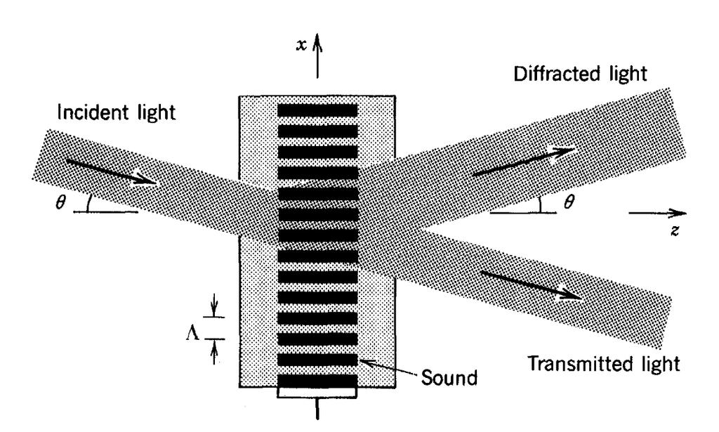
13 13 Braggs Diffraction A set of parallel reflectors separated by the wavelength of sound Λ will reflect light if the angle of incidence Ѳ satisfies the Bragg condition for constructive interference, Sin Ѳ = /2Λ - wavelength of incident light, Λ - wave length of sound This form of light-sound interaction is known as Bragg diffraction, Bragg reflection, or Bragg scattering. The device that produces this effect is known as a Bragg reflector, a Bragg deflector, or a Bragg cell. Acousto-Optic Materials Fused Silica Lithium Niobate Arsenic Trisulfide Tellurium dioxide Telluride glasses Gallium Phosphide The selection of acousto optic material depends upon the specific application. An AO material suitable for one application may not applicable to another. For example, GaP is useful to make modulators and deflectors but it is not suitable for filter purposes since it is optically isotropic. Various Acousto Optic effects and Applications Effect Meaning Devices Deflection The angular deviation in the Acousto Deflectors, diffracted light beam is proportional Routers, Switches, to the acoustic frequency Optical Scanners Intensity Diffracted beam intensity is a Amplitude Variation function of acoustic power Modulators, Q- Switches
14 14 Frequency Shift Filtering A frequency shift is introduced by the acoustic interaction (± f acoustic frequency) Wave length selection can be carried out with large spectral band sources since only one wavelength will match the condition (for ex. Bragg) Fixed or Variable Frequency shifter Tunnable Wavelength Filter, Isolators Examples Acoustic Spectrum Analyzer A sound wave containing spectrum of different frequencies disperses the light in different directions with the intensity of deflected light in a given direction proportional to the sound component at the corresponding frequency. Fig. The acousto-optic cell serves as an acoustic spectrum analyzer Fig. Routing an optical beam to one of N directions
15 15 Optical Router An acousto-optic cell can be used as an interconnection optical switch that routes information carried by one or more optical beams to one or more selected directions. An acousto-optic cell in which the frequency of the acoustic wave is one of N possible values f1,f2,... fn deflects an incident optical beam to one of N corresponding directions Ѳ1,Ѳ2,... ѲN. By applying an acoustic wave of frequency fi, the optical beam is deflected by an angle Ѳi and routed to point i. Magnetostriction Magnetostriction is a property of materials that causes them to change their shape or dimensions when it is subjected to a magnetic field. Most ferromagnetic materials such as iron, nickel, and cobalt exhibit some measurable magnetostriction. This effect was first identified by James Joule (1842) when observing a sample of iron. This effect causes energy losses due to frictional heating in susceptible ferromagnetic cores. The effect is also responsible for the high pitch buzzing sound that can be heard near transformers carrying alternating current, near fluorescent light ballast. Principle The magnetostrictive effect is due to the interaction of an external magnetic field with the internal domains. Internally, ferromagnetic materials have a structure that is divided into domains, each of which is a region of uniform magnetic polarization. When a material is not magnetized, the internal magnetic domains are randomly arranged. When the material is magnetized, the domains are oriented with their axes approximately parallel to one another. This orientation and reorientation

16 16 causes micro strain in the dimension of the material. The following figures show the change in dimension (e) due to the field H. Fig. Volume change of MS material. The volume change can be positive or negative depending on the material. The effect is the same regardless of the polarity of the magnetic field. The mechanism of Magnetostriction at an atomic level is relatively complex but on a macroscopic level it may be segregated into two distinct processes. 1) The first process is dominated by the migration of domain walls within the material in response to external magnetic fields. 2) Second, is the rotation of the domains. These two mechanisms allow the material to change the domain orientation which in turn causes a dimensional change. There are two kinds of Magnetostriction.
17 17 (i) Volume (isotropic) Magnetostriction. (ii) Joule (anisotropic) Magnetostriction. In Volume magnetostriction the magnetic fields leads to an isotropic change of the shape in all dimensions. The volume change is described by the magnetostriction factor = V/V. Joule magnetostriction leads to a change of shape in the direction of the magnetic field, while maintaining a constant volume. A magnetostriction factor (strain) can be defined: = L /L In general Volume magnetostriction is far smaller than Joule magnetostriction ( >> ). The magnetostriction coefficient can be positive or negative. For a positive the material expands in the direction of the applied magnetic field, while for a negative it shrinks. Magnetostrictive coefficient L is defined as the fractional change in length as the magnetization increases from zero to its saturation value. The coefficient L may be positive or negative, and is usually on the order of Materials At room temperature the highest magnetostriction obtained in pure cobalt (Co) is very small and is about 60 microstrain. But by alloying elements it is possible to achieve very high magnetostriction under relatively small fields.
18 18 The highest known magnetostriction materials are those Iron alloys containing the rare earth elements Dysprosium (Dy) or Terbium ( Tb) : DyFe2, and TbFe2. However, these materials have tremendous magnetic anisotropy which needs a very large magnetic field to drive the magnetostriction. Terfenol-D (Alloy containing Fe, Dy and Tb: TbxDy1-xFe2), strains to about 2000 microstrain in a field of 2 koe at room temperatures. For typical transducer and actuator applications, Terfenol-D is the most commonly used engineering magnetostrictive material. Inverse Magnetostrictive effect: Villari effect The reciprocal effect, the change of the susceptibility (change in magnetic property) of a material when subjected to a mechanical stress is known as Villari effect. The Wiedemann effect The twisting of a ferromagnetic rod through which an electric current is flowing when the rod is placed in a longitudinal magnetic field. It is one of the manifestations of magnetostriction in a field formed by the combination of a longitudinal magnetic field and a circular magnetic field that is created by an electric current. If the electric current (or the magnetic field) is alternating, the rod will begin torsional oscillation. Applications Magnetostrictive materials transduce or convert magnetic energy to mechanical energy and vice versa. This ability to convert an amount of energy from one form into another allows the use of magnetostrictive materials in actuator and sensor applications. Following Fig. shows various physical effects which are related to the magnetostrictive effect.
19 19 Magnetostriction can be used to create vibrators - some lever action is used in conjunction with the magnetic deformation to increase the resultant amplitude of vibration. Used to produce ultrasonic vibrations either as a sound source or as ultrasonic waves in liquids which can act as a cleaning mechanism in ultrasonic cleaning devices. Sensors and Actuators The change in flux density can be detected by a pickup coil and is proportional to the level of the applied stress. Thus the Villari effect is used in sensor applications. Stress sensor used in applications such as monitoring stresses in bridge cables and nuclear power plant structures. Used in automobile suspension systems
20 20 The static magnetostrain of the materials permits building linear actuators offering large displacements (in µm) and large forces ( N) at low voltages. They can also be used as components of more complex actuators such as inchworm motors. Terfenol-D based actuators are available giving displacements up to 250μm and forces up to 2,200N, and operating at frequencies up to 2500 Hz. The operational temperature of this actuator is typically in the range from -20 C up to +100 C. In addition ultrasonic actuators for higher frequencies are available. Terfenol-D is also used to build compact linear motors. The central feature of this linear motor is a rod of Terfenol-D surrounded by an electric coil which, when energized, causes the rod to elongate. The actuator is mounted between two clamps. By operating the actuator and the clamps in an appropriate sequence the rod of smart material moves forwards or backwards. Position Sensors The interaction of a current pulse with the position magnet generates a strain pulse that travels down the waveguide and is detected by the pickup element.
21 21 The axial magnetic field is provided by a position magnet. The position magnet is attached to the machine tool, hydraulic cylinder, or whatever is being measured. The waveguide wire is enclosed within a protective cover and is attached to the stationary part of the machine, hydraulic cylinder, etc. The location of the position magnet is determined by first applying a current pulse to the waveguide. At the same time, a timer is started. The current pulse causes a sonic wave to be generated at the location of the position magnet Wiedemann effect. The sonic wave travels along the waveguide until it is detected by the pickup. This stops the timer. The elapsed time indicated by the timer then represents the distance between the position magnet and the pickup. The sonic wave also travels in the direction away from the pickup. In order to avoid an interfering signal from waves travelling in this direction, their energy is absorbed by a damping device (called the damp).
22 22 The pickup makes use of the Villari effect. A small piece of magnetostrictive material, called the tape, is welded to the waveguide near one end of the waveguide. This tape passes through a coil and is magnetized by a small permanent magnet called the bias magnet. When a sonic wave propagates down the waveguide and then down the tape, the stress induced by the wave causes a wave of changed permeability (Villari effect) in the tape. This in turn causes a change in the tape magnetic flux density, and thus a voltage output pulse is produced from the coil (Faraday effect). The voltage pulse is detected by the electronic circuitry and conditioned into the desired output. Electrostriction When an electric field is applied to an electrical insulator, that insulator might deform or change shape in some way. This property of the electrical insulator is called electrostriction. Specifically, electrostriction is the coupling between strain and electric field, or between strain and polarization; this coupling takes place only when an electric field is applied to the material. The Electrostrictive behavior (or electrostriction) is a phenomenon in which the dimension of material object changes in response to an applied electric field. It is due to the energy increase associated with the polarization induced by the external electric field in the material. The polarization may be due to atoms becoming egg-shaped rather than spheres, bonds between ions changing in length, or orientation of the permanent electric dipoles in the material. An electrostrictive material is centrosymmetrical in crystal structure, in contrast to piezoelectric or ferroelectric materials, which are non centrosymmetrical. The dimensional changes can be in all directions, in
23 23 contrast to the directional dimensional change in piezoelectricity or ferroelectricity. Also in contrast to piezoelectric or ferroelectric behavior, no voltage of field is created by electrostriction and an applied stress does not cause an electric field (i.e., no converse effect). Thus, electrostriction can be used for actuation, but not sensing. Electrostriction is a second-order effect (quadratic, nonlinear), i.e., the strain is proportional to the square of the electric field, or S = ME 2 where S is the strain, E is the electric field and M is the electrostrictive coefficient. (In contrast, piezoelectricity or ferroelectricity is a first order effect- Linear). The strain due to electrostriction is small compared to that due to piezoelectricity or ferroelectricity. For example, a field of 10 4 V/m produces 23 nm per meter in quartz (piezoelectric effect), but electrostrictive glass produces only 1 nm per meter. However, electrostrictive materials exhibit essentially no hysteresis upon cycling the electric field. Materials Although all dielectrics exhibit some electrostriction, certain engineered ceramics, known as relaxor ferroelectrics, have extraordinarily high electrostrictive constants. The most important electrostrictive materials are ceramics based on Pb(Mg1/3Nb2/3)O3, i.e., PMN or Lead Magnesium Niobate, which exhibits strains as high as 0.1% (i.e., 10 µm per cm) at moderate fields ( 10 6 V/m). The phenomenon is called giant electrostriction. These materials are also relaxor ferroelectrics. (i.e.) they are ferroelectrics below the Curie temperature, but electrostrictive above the Curie temperature. Also Lead Magnesium Niobate- Lead Titanate (PMN-PT) and Lead Lanthanum Zirconate Titanate (PLZT) are some other useful materials.
24 24 Applications Electrostrictive materials can be used to construct actuators, which can be used in control circuits where a small amount of force is required to turn on the circuit. These materials also react to electric fields very quickly, which makes these materials suitable for high-speed control circuits. An electrostrictive actuator is often made of electrostrictive polymer materials. Each polymer exhibits electrostriction differently. For example, silicone polymers might exhibit high strain performance when compared with other electrostrictive polymers. A polymer that has high strain performance is better suited to an environment in which mechanical strain might be an issue than a polymer with low strain performance. Other electrostrictive polymers such as polyurethane are capable of producing more force under the same electrical conditions than other polymers. Such a polymer allows more of the input electrical energy to be converted into mechanical work. Electrostrictive materials are often used in mechanical applications such as microangle adjusting devices, oil pressure servovalves and field-tunable piezoelectric transducers. Advantages Electrostriction occurs in certain materials that are poor conductors of electrical current. When a voltage differential is applied to electrostrictive materials, these materials undergo a temporary change in shape. Unlike magnetostriction, which is linear in nature, electrostriction is quadratic in nature. This nonlinear property of electrostriction allows the
25 25 electrostrictive materials to exhibit a reproducible strain response to electric fields without the losses to hysteresis and the resulting waste heat that magnetic materials produce. Electrostrictive materials have a high response speed often less than 10 milliseconds when an electric field is applied to the material. Quickresponse electrostrictive materials can be used in mechanical and electromechanical devices that require ultrafast circuit response times, such as precision instruments. Piezo Electric Effect The piezoelectric effect describes the relation between a mechanical stress and an electrical voltage in solids. Piezoelectricity is the ability of some materials such as crystals and certain ceramics, to generate an electric potential in response to applied mechanical stress. If the piezo crystals are not short-circuited, the applied stress induces a voltage across the material. It is simply, the appearance of an electric potential across certain faces of a crystal when it is subjected to mechanical pressure. A piezoelectric substance is one that produces an electric charge when a mechanical stress is applied (the substance is squeezed or stretched) used in sensor app. Converse PE effect A mechanical deformation (the substance shrinks or expands) is produced when an electric field is applied (useful in actuator application). The piezoelectric effect is a linear phenomenon where deformation is proportional to an electric field S = pe and D = dt
26 26 Where S is the mechanical strain p is the piezoelectric coefficient E is the electric filed D is the displancement (or charge density) linearly T is the stress These equations are known as direct and converse piezoelectric effect respectively. Piezoeletric materials Piezoelectric materials can be divided in 3 main groups: crystals, ceramics and Polymers Crystals Quartz SiO2 Gallium orthophosphate GaPO4 Ceramics Barium Titanate BaTiO3 Lead Zirconate Titanate PZT Polymers Polyvinylidene DiFluoride PVDF Theory of Piezoelectric Effect In order for a crystal to show the piezoelectric property it must have a polar axis. In order to have a polar axis the crystal must belong to a noncentrosymmetric crystal class (no center of symmetry)

27 27 When a crystal is subject to stress it may deform elastically. Ions will move. If opposite charges move away from or toward each other, a current is developed. If both charges move in the same direction no net current will develop. The current lasts only as long as the ions are in motion. Consider the individual molecules that make up the crystal. Each molecule has a polarization, one end is more negatively charged and the other end is positively charged, and is called a dipole. - This is a result of the atoms that make up the molecule and the way the molecules are shaped. The polar axis is an imaginary line that runs through the center of both charges on the molecule. In a monocrystal the polar axes of all of the dipoles lie in one direction. The crystal is said to be symmetrical because if the crystal is cut at any point, the resultant polar axes of the two pieces would lie in the same direction as the original.
28 28 In a polycrystal, there are different regions within the material that have a different polar axis. It is asymmetrical because there is no point at which the crystal could be cut that would leave the two remaining pieces with the same resultant polar axis. Fig a. shows the piezoelectric material without a stress or charge. Fig b. If the material is compressed, then a voltage of the same polarity as the poling voltage will appear between the electrodes. Fig c. If stretched, a voltage of opposite polarity will appear. Conversely, if a voltage is applied the material will deform Fig d. A voltage with the opposite polarity as the poling voltage will cause the material to expand. Fig. e. A voltage with the same polarity will cause the material to compress. Fig. f. If an AC signal is applied then the material will vibrate at the same frequency as the signal
29 29 Applications Generation of high voltage power sources Energy harvesting Electronic frequency generation, Microbalances, and Ultra fine focusing of optical assemblies. Sensors Detection and Generation of Sonar Waves Actuators Piezoelectric Motors Loudspeaker AFM and STM Inkjet Printers The piezoelectric crystal bends in different ways at different frequencies. This bending is called the vibration mode. The crystal can be made into various shapes to achieve different vibration modes like benders. To realize small, cost effective, and high performance products, several modes have been developed to operate over several frequency ranges (KHz- MHz). The ceramic piezoelectric materials are useful to build ceramic resonators, ceramic bandpass filters, ceramic discriminators, ceramic traps, SAW filters, and buzzers.
30 30 Piezoelectric Actuator Types Piezoelectric effect is the simple way of producing displacement useful in various actuator and motor concepts. Advantages of PE actuators Simple mechanical structure A short response time, An ability to create high forces, A high efficiency and a high mechanical durability. Drawbacks PE actuators have small strains: only % High supply voltage needed typically between 60 and 1000 Volts Hysteresis introduces a typical drift of a piezoelectric actuator. Types The three basic types of piezoelectric actuators are Stacks, Benders and Linear motors. Piezoelectric Stack Actuators The easiest way to produce a linear motion by the piezoelectric effect is to use a stack actuator, which is a multilayer construction: each stack is composed of several piezoelectric layers, as depicted in Figure. The required dimensions of the stack can be easily determined from the requirements of the application. The height is determined in respect to the desired movement and the cross sectional area in respect to the desired force. The stack having dimensions of 5x5x18 mm 3 provides a movement of 14.5 μm and a blocked force of 840 N.

31 31 Piezoelectric Benders Piezoelectric bending actuators (or piezoelectric cantilevers, or piezoelectric bimorphs) bear a close resemblance to bimetallic benders. The application of an electric field across the two layers of the bender result in one layer to expand, while the other contracts. The net result is a curvature much greater than the length or thickness deformation of the individual layers. With a piezoelectric bender, relatively high displacements can be achieved, but at the cost of force and speed. Fig.1. A serial bender arrangement with an anti-parallel polarization There are some benders that have only one piezoelectric layer on top of a metal layer (unimorph), but generally there are two piezoelectric layers and no metal (bimorph). This way, the displacement is doubled in comparison to a single layer version. If the number of piezoelectric layers exceeds two, the bender is referred as a multilayer. With thinner piezo layers, a smaller voltage is required to produce the same electric field strength, and therefore, the benefit of the multilayer benders is their lower
32 32 operating voltage. Bimorph and multilayer benders can be built into one of the two types: a serial or parallel bender. In a serial bender, there are two piezoelectric layers with an anti-parallel polarization connected to each other, and two surface electrodes, as shown in Figure 1. In this arrangement, one of the electrodes is connected to the ground and the other to the output of a bipolar amplifier. Parallel benders Parallel benders can be distinguished from serial benders by their three electrodes. In between the two parallel-polarized piezoelectric layers is a middle electrode, to which the actual control signal is supplied. The two surface electrodes are connected to the ground and to a fixed voltage. The control voltage is applied to the middle electrode, and it varies between zero and a fixed voltage. The parallel bender can also be connected in such a way that the two surface electrodes are connected to the ground and a bipolar signal is applied to the middle electrode. Piezoelectric Resonators/Filters Resonators are used to either generate waves of specific frequencies or to select specific frequencies from a signal. Musical instruments use acoustic resonators that produce sound waves of specific tones. When a piezoelectric body vibrates at its resonant frequency it absorbs considerably more energy than at other frequencies resulting in a dramatic decrease in the impedance. This phenomenon enables piezoelectric
33 33 materials to be used as a wave filter. A filter is required to pass a certain selected frequency band or to block a given band. The band width of a filter fabricated from a piezoelectric material is determined by the square of the coupling coefficient k, that is, it is nearly proportional to k 2. Quartz crystals with a very low k value of about 0.1 can pass very narrow frequency bands of approximately 1% of the center resonance frequency. On the other hand, PZT ceramics with a planar coupling coefficient of about 0.5 can easily pass a band of 10% of the center resonance frequency. The sharpness of the passband is dependent on the mechanical quality factor Qm(Mechanical Quality factor) of the materials. Quartz also has a very high Qm of about 106 which results in a sharp cut-off to the passband and a well-defined oscillation frequency. A simple resonator is a thin disc type, electroded on its plane faces and vibrating radially, for filter applications with a center frequency ranging from 200 khz to 1 MHz and with a bandwidth of several percent of the center frequency. For a frequency of 455 khz the disc diameter needs to be about 5.6 mm. However, if the required frequency is higher than 10 MHz, other modes of vibration such as the thickness extensional mode are exploited, because of its smaller size. The trapped-energy type filters made from PZT ceramics have been widely used in the intermediate frequency range for applications such as the 10.7 MHz FM radio receiver and transmitter. When the trappedenergy phenomena are utilized, the overtone frequencies are suppressed. The plate is partly covered with electrodes of a specific area and thickness. The fundamental frequency of the thickness mode of the ceramic beneath the electrode is less than that of the unelectroded portion, because of the extra inertia of the electrode mass. The lower-frequency wave of the electroded region cannot propagate into the unelectroded region. The
34 34 higher-frequency overtones, however, can propagate away into the unelectroded region. This is called the trapped-energy principle. Following figure shows a schematic drawing of a trapped-energy filter. In this structure the top electrode is split so that coupling between the two parts will only be efficient at resonance. More stable filters suitable for telecommunication systems have been made from single crystals such as quartz or LiTaO3. Piezo Ultrasonic Transducers Ultrasonic waves are now used in various fields. The sound source is made from piezoelectric ceramics as well as magnetostrictive materials. Piezoceramics are generally superior in efficiency and in size to magnetostrictive materials. In particular, hard piezoelectric materials with a high QM are preferable. A liquid medium is usually used for sound energy transfer. Ultrasonic washers, ultrasonic microphones for short-distance remote control and underwater detection, such as sonar and fish finding, and nondestructive testing are typical applications.
35 35 Ultrasonic scanning detectors are useful in medical electronics for clinical applications ranging from diagnosis to therapy and surgery. One of the most important applications is based on ultrasonic echo field. Ultrasonic transducers convert electrical energy into mechanical form when generating an acoustic pulse and convert mechanical energy into an electrical signal when detecting its echo. The transmitted waves propagate into a body and echoes are generated which travel back to be received by the same transducer. These echoes vary in intensity according to the type of tissue or body structure, thereby creating images. An ultrasonic image represents the mechanical properties of the tissue, such as density and elasticity. We can recognize anatomical structures in an ultrasonic image since the organ boundaries and fluid-to-tissue interfaces are easily discerned. The ultrasonic imaging process can also be done in real time. This means we can follow rapidly moving structures such as the heart without motion distortion. In addition, ultrasound is one of the safest diagnostic imaging techniques. It does not use ionizing radiation like x-rays and thus is routinely used for fetal and obstetrical imaging. Useful areas for ultrasonic imaging include cardiac structures, the vascular systems, the fetus and abdominal organs such as liver and kidney.
36 36 Surface Acoustic Wave Devices (SAW Devices) SAW A surface acoustic wave is an acoustic wave (mechanical wave) travelling along the surface of a material exhibiting elasticity, with an amplitude that typically decays exponentially with depth into the substrate. Ripple in water, waves travel along the surface of earth due to quake are all surface waves. Surface acoustic waves were discovered in 1885 by Lord Rayleigh, and are often named after him: Rayleigh waves. SAW devices have found numerous different applications in the field of communications and signal processing. SAW devices were initially used in radar, oscillators, and band pass filters for radio, TV and cellular telephones. In the last decade considerable work has been done in the development of SAW sensors of different types of high quality. Today SAW devices are used as temperature, pressure and stress sensors as well as chemical and biosensors. Principle of operation and Structure The operation of the SAW device is based on acoustic wave propagation near the surface of a piezoelectric solid. Piezoelectric materials are used for as electrical signals need to be transformed into the surface acoustic wave and vice versa. This implies that the wave can be trapped or otherwise modified while propagating. The displacements decay exponentially away from the surface, so that the most of the wave energy (usually more than 95%) is confined within a depth equal to one wavelength.
 of the input IDT electrode.")

37 37 Electronic SAW devices normally use one or more Inter Digital Transducers (IDTs). The IDT consists of a series of interleaved electrodes made of a metal film deposited on a piezoelectric substrate. The frequency of the generated waves can be changed by changing the pitch (inter electrode gap) of the input IDT electrode. Similarly, when SAW arrive at the output IDT, if the pitch of the IDT and SAW match, an electrical signal is generated between the IDT electrodes. The minimal electrode width which is obtained in industry is around 0.3μm, which determines the highest frequency of around 3 GHz. The input IDT is used to launch acoustic waves and the output IDT receives the electrical signals by the piezoelectric effect. The acoustic wave velocity depends on some extent on the type of piezoelectric substrate or kind of wave utilized. Even in the same substrate, the propagation characteristics (such as velocity, electromechanical coupling coefficient, temperature coefficient, propagation delay) of the SAW vary with the cutting angle or propagation direction. The input and output transducers may be equal or different. It depends upon the function which the SAW device has to perform. Usually they differ in electrode overlaps, number and sometimes positioning.

38 38 Working Principle A sinusoidal voltage v of frequency f applied to the input IDT forms an electric field which, through the piezoelectric effect causes a strain pattern of periodicity 2p, where p denotes the distance between the centres of the electrodes. If the frequency f is such that 2p is close to the surface wave wavelength, a surface wave will be launched in two opposite directions away from the transducer. The surface wave causes the corresponding electric field in the second transducer and correspondingly the voltage at the impedance ZL. Materials The commonly used substrate crystals are: quartz, lithium niobate, lithium tantalate, zincoxide and bismutgermanium oxide. They have different piezoelectric coupling coefficients and temperature sensitivities. ST quartz is used for most temperature stable devices. Applications Delay Lines The velocity of the acoustic wave (Vsaw) is a function of the substrate material and is in the range of 1500m/s to 4800m/s, which is 10 5 times lower than the electromagnetic wave velocity. This enables the construction of a small size delay line of a considerable delay (few Km).
39 39 Delay lines are very useful in producing echo effect, radar communications etc., Filter The magnitude of the output signal is the function of the ratio of the signal wavelength and the distance 2p. If the distance 2p is equal to the wavelength, the magnitude of the output voltage is maximal. The corresponding frequency is then called central or synchronous frequency of the device. The magnitude of the output voltage decays as the frequency shifts from the central frequency. It means that basically a SAW device is a transversal band pass filter. The phase characteristic is a function of the distances between the electrodes and the amplitude characteristic is a function of the electrodes number and lengths. If the electrodes are uniformly spaced, the phase characteristic is a linear function of frequency, e.g. the delay is constant in the appropriate frequency range. For an elemental SAW bandpass filter, the spacing between IDT fingers of alternating polarity is /2 at filter centre frequency f = v/.

40 40 Fig. SAW filter and Equivalent circuit Transversal filters have been commonly used as IF filters for TVs or filters in tuners for satellite broadcasting. They can be designed flexibly in frequency characteristics with some methods including varying the electrode finger overlap in the IDT. Resonators IDTs are only used as converters of electrical to mechanical signals and vice versa. Grating elements are used to get the reflections of the wave. Resonance can be generated by placing a grating at the propagation direction of a SAW excited by IDT. To reflect a surface acoustic wave with a wavelengh of, the pitch of the grating /2 can be used. A SAW resonator is a device that applies this phenomenon. A device with one IDT is called a one-port resonator, and a device with two IDTs for

41 41 input and output terminals between gratings is called a two-port resonator. The latter can be used as a filter for its propagation characteristics between IDTs. When the SAW resonator is used instead of the resistor and capacitor, the frequency is stabilized to the desired value. The signal frequency and the harmonics are optimized by fine tuning. SAW Sensors SAW devices are very sensitive and they are affected by stress, pressure, proximity of chemical substances, temperature, mass change etc. They are used as Sensors in applications include all areas of sensing (such as chemical, optical, thermal, pressure, acceleration, torque and biological). SAW sensors are a class of micro electro mechanical systems (MEMS) which rely on the modulation of surface acoustic waves to sense a physical phenomenon. The mechanical wave can be easily influenced by physical phenomena unlike an electrical signal. The device then transduces this wave back into an electrical signal. Changes in amplitude, phase, frequency, or time-delay between the input and output electrical signals can be used to measure the presence of the desired phenomenon.
42 42 Mass The accumulation of mass on the surface of an acoustic wave sensor will affect the surface acoustic wave as it travels across the delay line. The velocity v of a wave travelling through a solid is given by the expression V α E/ρ where E is Young s modulus and ρ is density of the material. Therefore, the wave velocity will decrease with added mass. This change can be measured by a change in time-delay or phase-shift between input and output signals. Chemical Vapours Chemical vapour sensors use the application of a thin film polymer across the delay line which selectively absorbs the gas or gases of interest. An array of such sensors with different polymeric coatings can be used to sense a large range of gases on a single sensor with resolution down to parts per trillion. Biological Matter A biologically-active layer can be placed between the interdigitated electrodes which contains immobilized antibodies. If the corresponding antigen is present in a sample, the antigen will bind to the antibodies, causing a mass-loading on the device. These sensors can be used to detect bacteria and viruses in samples, as well as to quantify the presence of certain mrna and proteins. Humidity Surface acoustic wave humidity sensors require a thermoelectric cooler in addition to a surface acoustic wave device. The thermoelectric cooler is placed below the surface acoustic wave device. Both are housed in a cavity with an inlet and outlet for gases. By cooling the device, water vapour will tend to condense on the surface of the device, causing a mass-loading.
43 43 Ultraviolet Radiation Surface acoustic wave devices can be made sensitive to optical wavelengths through the phenomena known as acoustic charge transport (ACT), which involves the interaction between a surface acoustic wave and photo generated charge carriers from a photo conducting layer. Ultraviolet radiation sensors employ the use of a thin film layer of zinc oxide across the delay line. When exposed to ultraviolet radiation, zinc oxide generates charge carriers which interact with the electric fields produced in the piezoelectric substrate by the travelling surface acoustic wave. This interaction decreases the velocity and the amplitude of the signal. Magnetic Fields Ferromagnetic materials, such as iron, nickel, and cobalt, exhibit a characteristic called magnetostriction, where the Young's modulus of the material is dependent on magnetic field strength. If a constant stress is maintained on such a material, the strain will change with a changing Young's modulus. If such a material is deposited in the delay line of a surface acoustic wave sensor, a change in length of the deposited film will stress the underlying substrate. This stress will result in a strain on the surface of the substrate, affecting the phase velocity, phase-shift, and timedelay of the signal. Viscosity Surface acoustic wave devices can be used to measure changes in viscosity of a liquid placed upon it. As the liquid becomes more viscous the resonant frequency of the device will change in correspondence. A network analyser is used to view the resonant frequency.
Doppler echocardiography & Magnetic Resonance Imaging. Doppler echocardiography. History: - Langevin developed sonar.
 1 Doppler echocardiography & Magnetic Resonance Imaging History: - Langevin developed sonar. - 1940s development of pulse-echo. - 1950s development of mode A and B. - 1957 development of continuous wave
PIEZOELECTRIC TECHNOLOGY PRIMER
 PIEZOELECTRIC TECHNOLOGY PRIMER James R. Phillips Sr. Member of Technical Staff CTS Wireless Components 4800 Alameda Blvd. N.E. Albuquerque, New Mexico 87113 Piezoelectricity The piezoelectric effect is
Module 6: Smart Materials & Smart Structural Control Lecture 33: Piezoelectric & Magnetostrictive Sensors and Actuators. The Lecture Contains:
 The Lecture Contains: Piezoelectric Sensors and Actuators Magnetostrictive Sensors and Actuators file:///d /chitra/vibration_upload/lecture33/33_1.htm[6/25/2012 12:42:09 PM] Piezoelectric Sensors and Actuators
e453.eps 1 Change (or the absolute value) in the measured physical variable 2 Change in the sensor property is translated into low-power-level
 in the measured physical variable 2 Change in the sensor property is translated into low-power-level") 3 Basic Phenomenon in Effect in Sensor Operation Sensors Prof. Dr. M. Zahurul Haq zahurul@me.buet.ac.bd http://teacher.buet.ac.bd/zahurul/ Department of Mechanical Engineering Bangladesh University of
3 Basic Phenomenon in Effect in Sensor Operation Sensors Prof. Dr. M. Zahurul Haq zahurul@me.buet.ac.bd http://teacher.buet.ac.bd/zahurul/ Department of Mechanical Engineering Bangladesh University of
COURSE OUTLINE. Introduction Signals and Noise Filtering Sensors: Piezoelectric Force Sensors. Sensors, Signals and Noise 1
 Sensors, Signals and Noise 1 COURSE OUTLINE Introduction Signals and Noise Filtering Sensors: Piezoelectric Force Sensors Piezoelectric Force Sensors 2 Piezoelectric Effect and Materials Piezoelectric
SENSORS and TRANSDUCERS
 SENSORS and TRANSDUCERS Tadeusz Stepinski, Signaler och system The Mechanical Energy Domain Physics Surface acoustic waves Silicon microresonators Variable resistance sensors Piezoelectric sensors Capacitive
Piezoelectric Materials and Devices
 Piezoelectric Materials and Devices Applications in Engineering and Medical Sciences M. S. VIJAYA CRC Press Taylor & Francis Croup Boca Raton London NewYork CRC Press is an imprint of the Taylor & Francis
Lecture 4: Anisotropic Media. Dichroism. Optical Activity. Faraday Effect in Transparent Media. Stress Birefringence. Form Birefringence
 Lecture 4: Anisotropic Media Outline Dichroism Optical Activity 3 Faraday Effect in Transparent Media 4 Stress Birefringence 5 Form Birefringence 6 Electro-Optics Dichroism some materials exhibit different
Supplementary Figure 1: SAW transducer equivalent circuit
 Supplementary Figure : SAW transducer equivalent circuit Supplementary Figure : Radiation conductance and susceptance of.6um IDT, experiment & calculation Supplementary Figure 3: Calculated z-displacement
Transduction Based on Changes in the Energy Stored in an Electrical Field
 Lecture 7-1 Transduction Based on Changes in the Energy Stored in an Electrical Field - Electrostriction The electrostrictive effect is a quadratic dependence of strain or stress on the polarization P
Optical and Photonic Glasses. Lecture 30. Femtosecond Laser Irradiation and Acoustooptic. Professor Rui Almeida
 Optical and Photonic Glasses : Femtosecond Laser Irradiation and Acoustooptic Effects Professor Rui Almeida International Materials Institute For New Functionality in Glass Lehigh University Femto second
Overview. Sensors? Commonly Detectable Phenomenon Physical Principles How Sensors Work? Need for Sensors Choosing a Sensor Examples
 Intro to Sensors Overview Sensors? Commonly Detectable Phenomenon Physical Principles How Sensors Work? Need for Sensors Choosing a Sensor Examples Sensors? American National Standards Institute A device
DYNAMIC ROTARY TORQUE MEASUREMENT USING SURFACE ACOUSTIC WAVES
 DYNAMIC ROTARY TORQUE MEASUREMENT USING SURFACE ACOUSTIC WAVES Abstract A. Lonsdale Technical Director Sensor Technology Ltd The subject of torque measurement has previously been addressed extensively.
GCSE PHYSICS REVISION LIST
 GCSE PHYSICS REVISION LIST OCR Gateway Physics (J249) from 2016 Topic P1: Matter P1.1 Describe how and why the atomic model has changed over time Describe the structure of the atom and discuss the charges
Active elastomer components based on dielectric elastomers
 Gummi Fasern Kunststoffe, 68, No. 6, 2015, pp. 412 415 Active elastomer components based on dielectric elastomers W. Kaal and S. Herold Fraunhofer Institute for Structural Durability and System Reliability
Piezoelectric Resonators ME 2082
 Piezoelectric Resonators ME 2082 Introduction K T : relative dielectric constant of the material ε o : relative permittivity of free space (8.854*10-12 F/m) h: distance between electrodes (m - material
Piezo Theory: Chapter 1 - Physics & Design
 Piezoelectric effect inverse piezoelectric effect The result of external forces to a piezoelectric material is positive and negative electrical charges at the surface of the material. If electrodes are
ME 515 Mechatronics. Overview of Computer based Control System
 ME 515 Mechatronics Introduction to Sensors I Asanga Ratnaweera Department of Faculty of Engineering University of Peradeniya Tel: 081239 (3627) Email: asangar@pdn.ac.lk Overview of Computer based Control
Solid State Physics (condensed matter): FERROELECTRICS
: FERROELECTRICS") Solid State Physics (condensed matter): FERROELECTRICS Prof. Igor Ostrovskii The University of Mississippi Department of Physics and Astronomy Oxford, UM: May, 2012 1 People: Solid State Physics Condensed
Solid State Physics (condensed matter): FERROELECTRICS Prof. Igor Ostrovskii The University of Mississippi Department of Physics and Astronomy Oxford, UM: May, 2012 1 People: Solid State Physics Condensed
Classification of Dielectrics & Applications
 Classification of Dielectrics & Applications DIELECTRICS Non-Centro- Symmetric Piezoelectric Centro- Symmetric Pyroelectric Non- Pyroelectric Ferroelectrics Non-Ferroelectric Piezoelectric Effect When
INTRODUCTION TO PIEZO TRANSDUCERS
 PIEZO SYSTEMS, INC. 65 Tower Office Park Woburn, MA 01801 USA Tel: 781 933 4850 Fax: 781 933 4743 email: sales@piezo.com Find Search for a product or category HOME PRODUCTS CUSTOM OEM CATALOG TECHNICAL
Linear Magnetostrictive Models in Comsol
 Presented at the COMSOL Conference 2009 Boston ETREMA Products, Inc. Linear Magnetostrictive Models in Comsol Comsol Conference 2009 October 8-10, 2009 Boston, MA 10/23/2009 Sponsored in part by ONR Contract
Measurement Techniques for Engineers. Motion and Vibration Measurement
 Measurement Techniques for Engineers Motion and Vibration Measurement Introduction Quantities that may need to be measured are velocity, acceleration and vibration amplitude Quantities useful in predicting
Finite Element Analysis of Piezoelectric Cantilever
 Finite Element Analysis of Piezoelectric Cantilever Nitin N More Department of Mechanical Engineering K.L.E S College of Engineering and Technology, Belgaum, Karnataka, India. Abstract- Energy (or power)
The Use of Multiphysics Models in the Design and Simulation of Magnetostrictive Transducers. Dr. Julie Slaughter ETREMA Products, Inc Ames, IA
 The Use of Multiphysics Models in the Design and Simulation of Magnetostrictive Transducers Dr. Julie Slaughter ETREMA Products, Inc Ames, IA 1 ETREMA Products, Inc. Designer and manufacturer of technology
Piezo materials. Actuators Sensors Generators Transducers. Piezoelectric materials may be used to produce e.g.: Piezo materials Ver1404
 Noliac Group develops and manufactures piezoelectric materials based on modified lead zirconate titanate (PZT) of high quality and tailored for custom specifications. Piezoelectric materials may be used
PRE-BOARD EXAMINATION STD : XII MARKS : 150
 PRE-BOARD EXAMINATION STD : XII MARKS : 150 SUB : PHYSICS TIME : 3.00 Hrs I.Choose the correct answer: 30x1=30 1.Which of the following quantities not a scalar? a)electric flux b) electric potential c)
INSTRUMENTATION ECE Fourth Semester. Presented By:- Sumit Grover Lect., Deptt. of ECE
 INSTRUMENTATION ECE Fourth Semester Presented By:- Sumit Grover Lect., Deptt. of ECE Detailed Contents Objectives Sensors and transducer Classification of transducers Temperature transducers Resistance
Overview. Sensors? Commonly Detectable Phenomenon Physical Principles How Sensors Work? Need for Sensors Choosing a Sensor Examples
 Intro to Sensors Overview Sensors? Commonly Detectable Phenomenon Physical Principles How Sensors Work? Need for Sensors Choosing a Sensor Examples Sensors? American National Standards Institute A device
SURFACE ACOUSTIC WAVE FERROELECTRIC PHONONIC CRYSTAL TUNABLE BY ELECTRIC FIELD
 NANOSYSTEMS: PHYSICS, CHEMISTRY, MATHEMATICS, 2013, 4 (5), P. 630 634 SURFACE ACOUSTIC WAVE FERROELECTRIC PHONONIC CRYSTAL TUNABLE BY ELECTRIC FIELD V. P. Pashchenko 1,2 1 Saint Petersburg State Polytechnical
Lecture 19. Measurement of Solid-Mechanical Quantities (Chapter 8) Measuring Strain Measuring Displacement Measuring Linear Velocity
 Measuring Strain Measuring Displacement Measuring Linear Velocity") MECH 373 Instrumentation and Measurements Lecture 19 Measurement of Solid-Mechanical Quantities (Chapter 8) Measuring Strain Measuring Displacement Measuring Linear Velocity Measuring Accepleration and
MECH 373 Instrumentation and Measurements Lecture 19 Measurement of Solid-Mechanical Quantities (Chapter 8) Measuring Strain Measuring Displacement Measuring Linear Velocity Measuring Accepleration and
DEVIL PHYSICS THE BADDEST CLASS ON CAMPUS IB PHYSICS
 DEVIL PHYSICS THE BADDEST CLASS ON CAMPUS IB PHYSICS TSOKOS OPTION I-2 MEDICAL IMAGING Reading Activity Answers IB Assessment Statements Option I-2, Medical Imaging: X-Rays I.2.1. I.2.2. I.2.3. Define
ESO 205 Nature and Properties of Materials
 Dielectric Materials Topics to discuss Principles of dielectrics Dielectrics Loss and Breakdown Polarizations Frequency dependence Ferro-, Piezo- and Pyro- electrics ESO 205 Nature and Properties of Materials
YEAR 11- Physics Term 1 plan
 YEAR 11- Physics Term 1 plan 2016-2017 Week Topic Learning outcomes Week 1 5.1.2 Nucleus of the Atom Describe the composition of the nucleus in terms of protons and neutrons State the charges of protons
Finite Element Modeling of Ultrasonic Transducers for Polymer Characterization
 Excerpt from the Proceedings of the COMSOL Conference 2009 Milan Finite Element Modeling of Ultrasonic Transducers for Polymer Characterization Serena De Paolis *, Francesca Lionetto and Alfonso Maffezzoli
Institute for Electron Microscopy and Nanoanalysis Graz Centre for Electron Microscopy
 Institute for Electron Microscopy and Nanoanalysis Graz Centre for Electron Microscopy Micromechanics Ass.Prof. Priv.-Doz. DI Dr. Harald Plank a,b a Institute of Electron Microscopy and Nanoanalysis, Graz
Addition 1. Shear Stack Piezoelectric Elements and Shear Effect Basics
 120 Addition 1 Shear Stack Piezoelectric Elements and Shear Effect Basics Introduction The STM scanner built up in this work is a Besocke type scanner (see room temperature STM instrumental chapter). The
Piezoelectric sensing and actuation CEE575
 Piezoelectric sensing and actuation CEE575 Sensor: Mechanical energy to electrical energy Actuator: Electrical energy converted to mechanical energy (motion) Materials For many years, natural crystals
Sensing and Sensors: Fundamental Concepts
 Sensing and Sensors: Fundamental Concepts 2015 Sensitivity Range Precision Accuracy Resolution Offset Hysteresis Response Time Source: sensorwebs.jpl.nasa.gov Human Physiology in Space" by Barbara F. Abuja
e453.eps 1 Change (or the absolute value) in the measured physical variable 2 Change in the sensor property is translated into low-power-level
 in the measured physical variable 2 Change in the sensor property is translated into low-power-level") 3 Basic Phenomenon in Effect in Sensor Operation Measurement & Sensors Prof. Dr. M. Zahurul Haq http://teacher.buet.ac.bd/zahurul/ Department of Mechanical Engineering Bangladesh University of Engineering
3 Basic Phenomenon in Effect in Sensor Operation Measurement & Sensors Prof. Dr. M. Zahurul Haq http://teacher.buet.ac.bd/zahurul/ Department of Mechanical Engineering Bangladesh University of Engineering
Electrical Properties
 Electrical Properties Electrical Conduction R Ohm s law V = IR I l Area, A V where I is current (Ampere), V is voltage (Volts) and R is the resistance (Ohms or ) of the conductor Resistivity Resistivity,
4. Circular Dichroism - Spectroscopy
 4. Circular Dichroism - Spectroscopy The optical rotatory dispersion (ORD) and the circular dichroism (CD) are special variations of absorption spectroscopy in the UV and VIS region of the spectrum. The
PROPERTY STUDY ON EMATS WITH VISUALIZATION OF ULTRASONIC PROPAGATION
 More Info at Open Access Database www.ndt.net/?id=18576 PROPERTY STUDY ON EMATS WITH VISUALIZATION OF ULTRASONIC PROPAGATION T. Yamamoto, T. Furukawa, I. Komura Japan Power Engineering and Inspection Corporation,
An Energy Circulation Driving Surface Acoustic Wave Motor
 An Energy Circulation Driving Surface Acoustic Wave Motor Minoru K. Kurosawa Tokyo Institute of Technology Yokohama, Japan mkur@ae.titech.ac.jp Purevdagva Nayanbuu Tokyo Institute of Technology Yokohama,
7 Optical modulators. 7.1 Electro-optic modulators Electro-optic media
 7.1 Electro-optic modulators 7.1.1 Electro-optic media In a linear anisotropic medium, the electric displacement field D and the electric field strength E are related to each other through the electric
ELG4112. Electromechanical Systems and Mechatronics
 ELG4112 Electromechanical Systems and Mechatronics 1 Introduction Based on Electromechanical Systems, Electric Machines, and Applied Mechatronics Electromechanical systems integrate the following: Electromechanical
Today s menu. Last lecture. Measurement of volume flow rate. Measurement of volume flow rate (cont d...) Differential pressure flow meters
 Differential pressure flow meters") Last lecture Analog-to-digital conversion (Ch. 1.1). Introduction to flow measurement systems (Ch. 12.1). Today s menu Measurement of volume flow rate Differential pressure flowmeters Mechanical flowmeters
Last lecture Analog-to-digital conversion (Ch. 1.1). Introduction to flow measurement systems (Ch. 12.1). Today s menu Measurement of volume flow rate Differential pressure flowmeters Mechanical flowmeters
SENSORS AND TRANSDUCERS
 Electrical Measurements International Program Department of Electrical Engineering UNIVERSITAS INDONESIA ANDRITTO ABDUL GHAFFAR ANDHIKA ADIEL INSANI Lecturer : Ir. Chairul Hudaya, ST, M.Eng., Ph.D., IPM
Semiconductor Optoelectronics Prof. M. R. Shenoy Department of Physics Indian Institute of Technology, Delhi
 Semiconductor Optoelectronics Prof. M. R. Shenoy Department of Physics Indian Institute of Technology, Delhi Lecture - 1 Context and Scope of the Course (Refer Slide Time: 00:44) Welcome to this course
Principles of Active Vibration Control: Piezoelectric materials
 Principles of Active Vibration Control: Piezoelectric materials Introduction: Piezoelectric materials are materials that produce a voltage when stress is applied. Since, this effect also applies in the
Personalised Learning Checklists AQA Physics Paper 2
 4.5.1 Forces and their interactions 4.5.2 Work done and energy transfer AQA Physics (8463) from 2016 Topics P4.5. Forces Topic Student Checklist R A G Identify and describe scalar quantities and vector
Liquid Crystals IAM-CHOON 1(1100 .,4 WILEY 2007 WILEY-INTERSCIENCE A JOHN WILEY & SONS, INC., PUBLICATION. 'i; Second Edition. n z
 Liquid Crystals Second Edition IAM-CHOON 1(1100.,4 z 'i; BICENTCNNIAL 1 8 0 7 WILEY 2007 DICENTENNIAL n z z r WILEY-INTERSCIENCE A JOHN WILEY & SONS, INC., PUBLICATION Contents Preface xiii Chapter 1.
Lab #13: Polarization
 Lab #13: Polarization Introduction In this experiment we will investigate various properties associated with polarized light. We will study both its generation and application. Real world applications
Mandatory Assignment 2013 INF-GEO4310
 Mandatory Assignment 2013 INF-GEO4310 Deadline for submission: 12-Nov-2013 e-mail the answers in one pdf file to vikashp@ifi.uio.no Part I: Multiple choice questions Multiple choice geometrical optics
1. In Young s double slit experiment, when the illumination is white light, the higherorder fringes are in color.
 TRUE-FALSE STATEMENTS: ELECTRICITY: 1. Electric field lines originate on negative charges. 2. The flux of the electric field over a closed surface is proportional to the net charge enclosed by the surface.
Lasers and Electro-optics
 Lasers and Electro-optics Second Edition CHRISTOPHER C. DAVIS University of Maryland III ^0 CAMBRIDGE UNIVERSITY PRESS Preface to the Second Edition page xv 1 Electromagnetic waves, light, and lasers 1
Technical University of Denmark
 Technical University of Denmark Page 1 of 11 pages Written test, 9 December 2010 Course name: Introduction to medical imaging Course no. 31540 Aids allowed: none. "Weighting": All problems weight equally.
Instrumentation and Operation
 Instrumentation and Operation 1 STM Instrumentation COMPONENTS sharp metal tip scanning system and control electronics feedback electronics (keeps tunneling current constant) image processing system data
ACOUSTIC EMISSION MEASUREMENTS ON PIEZOELECTRIC/ FERROELECTRIC MATERIALS
 ACOUSTIC EMISSION MEASUREMENTS ON PIEZOELECTRIC/ FERROELECTRIC MATERIALS HIDEAKI ABURATANI Kitakyushu National College of Technology, Kokura-minami, Kitakyushu, Fukuoka, Japan Abstract Ferroelectric materials
KTN Crystals Open Up New Possibilities and Applications
 : KTN Crystal Technologies KTN Crystals Open Up New Possibilities and Applications Shogo Yagi Abstract By exploiting the giant electro-optic effect of potassium tantalate niobate (KTN) crystal, we have
Two point charges, A and B, lie along a line separated by a distance L. The point x is the midpoint of their separation.
 Use the following to answer question 1. Two point charges, A and B, lie along a line separated by a distance L. The point x is the midpoint of their separation. 1. Which combination of charges would yield
EE 5344 Introduction to MEMS CHAPTER 6 Mechanical Sensors. 1. Position Displacement x, θ 2. Velocity, speed Kinematic
 I. Mechanical Measurands: 1. Classification of main types: EE 5344 Introduction MEMS CHAPTER 6 Mechanical Sensors 1. Position Displacement x, θ. Velocity, speed Kinematic dx dθ v =, = ω 3. Acceleration
Slide 1. Temperatures Light (Optoelectronics) Magnetic Fields Strain Pressure Displacement and Rotation Acceleration Electronic Sensors
 Magnetic Fields Strain Pressure Displacement and Rotation Acceleration Electronic Sensors") Slide 1 Electronic Sensors Electronic sensors can be designed to detect a variety of quantitative aspects of a given physical system. Such quantities include: Temperatures Light (Optoelectronics) Magnetic
Slide 1 Electronic Sensors Electronic sensors can be designed to detect a variety of quantitative aspects of a given physical system. Such quantities include: Temperatures Light (Optoelectronics) Magnetic
Modulators. Tuesday, 11/14/2006 Physics 158 Peter Beyersdorf. Document info 17. 1
 Modulators Tuesday, 11/14/2006 Physics 158 Peter Beyersdorf Document info 17. 1 Class Outline Birefringence Optical Activity Faraday Rotation Optical Modulators Electrooptic Modulators Accoustooptic Modulators
Chapter 2 Surface Acoustic Wave Motor Modeling and Motion Control
 Chapter 2 Surface Acoustic Wave Motor Modeling and Motion Control 1 Abstract For miniaturization of ultrasonic transducers, a surface acoustic wave device has an advantage in rigid mounting and high-power-density
NDT&E Methods: UT Ultrasound Generation
 CAVITY INSPECTION NDT&E Methods: UT Ultrasound Generation VJ Technologies NDT&E Methods: UT 6. NDT&E: Introduction to Methods 6.1. Ultrasonic Testing: Basics of Elasto-Dynamics 6.2. Ultrasonic Testing:
MODEL TEST - 1 PHYSICS
 MODEL TEST - 1 PHYSICS [Time: 3 Hrs] [Max. Marks: 70] Note: 1. All questions are compulsory. 2. Neat diagrams must be drawn wherever necessary. 3. Figures to the right indicate full marks. 4. Use of only
Surface Magnetic Non-Destructive Testing
 Surface Magnetic Non-Destructive Testing Evangelos Hristoforou 1,*, Konstantinos Kosmas 1 and Eleftherios Kayafas 2 1 School of Mining and Metallurgy Engineering, National Technical University of Athens,
Maxwell s equations and EM waves. From previous Lecture Time dependent fields and Faraday s Law
 Maxwell s equations and EM waves This Lecture More on Motional EMF and Faraday s law Displacement currents Maxwell s equations EM Waves From previous Lecture Time dependent fields and Faraday s Law 1 Radar
Matter mass space atoms solid, a liquid, a gas, or plasm elements compounds mixtures atoms Compounds chemically combined Mixtures not chemically
 SOL PS.2 THE NATURE OF MATTER Matter is anything that has mass and occupies space. All matter is made up of small particles called atoms. Matter can exist as a solid, a liquid, a gas, or plasma. Matter
CAMI - Science. CAPS - Physics Links Grade 10
 CAMI - Science CAPS - Physics Links Grade 10 TERM 1 TOPICS CONTENT, CONCEPTS & SKILLS CAMI - KEYSTROKES Transverse pulses on a string or spring Pulse, amplitude Define a pulse Define a transverse pulse
Chiroptical Spectroscopy
 Chiroptical Spectroscopy Theory and Applications in Organic Chemistry Lecture 2: Polarized light Masters Level Class (181 041) Mondays, 8.15-9.45 am, NC 02/99 Wednesdays, 10.15-11.45 am, NC 02/99 28 Electromagnetic
Outline. 4 Mechanical Sensors Introduction General Mechanical properties Piezoresistivity Piezoresistive Sensors Capacitive sensors Applications
 Sensor devices Outline 4 Mechanical Sensors Introduction General Mechanical properties Piezoresistivity Piezoresistive Sensors Capacitive sensors Applications Introduction Two Major classes of mechanical
OPTI510R: Photonics. Khanh Kieu College of Optical Sciences, University of Arizona Meinel building R.626
 OPTI510R: Photonics Khanh Kieu College of Optical Sciences, University of Arizona kkieu@optics.arizona.edu Meinel building R.626 Announcements HW#3 is assigned due Feb. 20 st Mid-term exam Feb 27, 2PM
Sensors Lecture #5: Position and Displacement using Resistive, Capacitive and Inductive Sensors
 Sensors Lecture #5: Position and Displacement using Resistive, Capacitive and Inductive Sensors Jerome P. Lynch Department of Civil and Environmental Engineering Department of Electrical Engineering and
KERR EFFECT. Monochromatic, vertically polarized light impinges on a PLZT element (leadlanthanum-zirconium-titanium
 KERR EFFECT OBJECTVE 1. The phase-shift between the normal and the extra-ordinary light beam is to be recorded for different voltages applied to the PLZT-element respectively for different electric field
St Olave s Grammar School. AS Physics Mock Revision Checklist
 St Olave s Grammar School Mock Practical skills.. a Can you design experiments, including ones to solve problems set in a practical context?.. b Can you identify the variables that must be controlled in
Optics Definitions. The apparent movement of one object relative to another due to the motion of the observer is called parallax.
 Optics Definitions Reflection is the bouncing of light off an object Laws of Reflection of Light: 1. The incident ray, the normal at the point of incidence and the reflected ray all lie in the same plane.
Wave Motions and Sound
 EA Notes (Scen 101), Tillery Chapter 5 Wave Motions and Sound Introduction Microscopic molecular vibrations determine temperature (last Chapt.). Macroscopic vibrations of objects set up what we call Sound
18. Active polarization control
 18. Active polarization control Ways to actively control polarization Pockels' Effect inducing birefringence Kerr Effect Optical Activity Principal axes are circular, not linear Faraday Effect inducing
phase retardance THz intensity ratio THz filling factor in air : 0.2 filling factor in si : 0.8 length of air : 4um length of si : 16um depth : 27.
 3. Research on THz-wave applications using frequency-agile THz-wave source 3.1 Development of spectroscopic Stokes polarimeter by using tunable THz-wave source (T. Notake, H. Minamide) In THz frequency
Chapter 24 Photonics Question 1 Question 2 Question 3 Question 4 Question 5
 Chapter 24 Photonics Data throughout this chapter: e = 1.6 10 19 C; h = 6.63 10 34 Js (or 4.14 10 15 ev s); m e = 9.1 10 31 kg; c = 3.0 10 8 m s 1 Question 1 Visible light has a range of photons with wavelengths
STRAIN GAUGES YEDITEPE UNIVERSITY DEPARTMENT OF MECHANICAL ENGINEERING
 STRAIN GAUGES YEDITEPE UNIVERSITY DEPARTMENT OF MECHANICAL ENGINEERING 1 YEDITEPE UNIVERSITY ENGINEERING FACULTY MECHANICAL ENGINEERING LABORATORY 1. Objective: Strain Gauges Know how the change in resistance
PHYSICS 2005 (Delhi) Q3. The power factor of an A.C. circuit is 0.5. What will be the phase difference between voltage and current in this circuit?
 Q3. The power factor of an A.C. circuit is 0.5. What will be the phase difference between voltage and current in this circuit?") General Instructions: 1. All questions are compulsory. 2. There is no overall choice. However, an internal choke has been pro vided in one question of two marks, one question of three marks and all three
General Instructions: 1. All questions are compulsory. 2. There is no overall choice. However, an internal choke has been pro vided in one question of two marks, one question of three marks and all three
Wave Motion and Sound
 Wave Motion and Sound 1. A back and forth motion that repeats itself is a a. Spring b. Vibration c. Wave d. Pulse 2. The number of vibrations that occur in 1 second is called a. A Period b. Frequency c.
Lecture 4 Scanning Probe Microscopy (SPM)
") Lecture 4 Scanning Probe Microscopy (SPM) General components of SPM; Tip --- the probe; Cantilever --- the indicator of the tip; Tip-sample interaction --- the feedback system; Scanner --- piezoelectric
Lecture 4 Scanning Probe Microscopy (SPM) General components of SPM; Tip --- the probe; Cantilever --- the indicator of the tip; Tip-sample interaction --- the feedback system; Scanner --- piezoelectric
Electromagnetics in COMSOL Multiphysics is extended by add-on Modules
 AC/DC Module Electromagnetics in COMSOL Multiphysics is extended by add-on Modules 1) Start Here 2) Add Modules based upon your needs 3) Additional Modules extend the physics you can address 4) Interface
Physics 9e/Cutnell. correlated to the. College Board AP Physics 2 Course Objectives
 correlated to the College Board AP Physics 2 Course Objectives Big Idea 1: Objects and systems have properties such as mass and charge. Systems may have internal structure. Enduring Understanding 1.A:
Chapter 31 Maxwell s Equations and Electromagnetic Waves. Copyright 2009 Pearson Education, Inc.
 Chapter 31 Maxwell s Equations and Electromagnetic Waves Units of Chapter 31 Changing Electric Fields Produce Magnetic Fields; Ampère s Law and Displacement Current Gauss s Law for Magnetism Maxwell s
High School. Prentice Hall. Conceptual Physics South Carolina Science Academic Standards - Physics High School
 Prentice Hall Conceptual Physics 2009 High School C O R R E L A T E D T O High School Scientific Inquiry Standard P-1: The student will demonstrate an understanding of how scientific inquiry and technological
ECE421: Electronics for Instrumentation MEP382: Design of Applied Measurement Systems Lecture #2: Transduction Mechanisms
 ECE421: Electronics for Instrumentation MEP382: Design of Applied Measurement Systems Lecture #2: Transduction Mechanisms Mostafa Soliman, Ph.D. April 28 th 2014 Slides are borrowed from Dr. Moahmed Elshiekh
Year 10 End of Year Examination Revision Checklist
 St Olave s Physics Department Year 10 of Year Examination Revision Checklist The following checklists include all the topics that will be included in the Year 10 of Year exam. Students should use the tickboxes
Engineering Physics 1 Dr. M. K. Srivastava Department of Physics Indian Institute of Technology-Roorkee. Module-02 Lecture-03 Ultrasonics
 Engineering Physics 1 Dr. M. K. Srivastava Department of Physics Indian Institute of Technology-Roorkee Module-02 Lecture-03 Ultrasonics In the last lecture which was the second one of the series on acoustics,
General Instructions :
 Class XII Subject - Physics General Instructions : 1. All questions are compulsory. 2. Q. 1 to 5 are Very short Answer type questions (1 Mark each. ) 3. Q. 6 to 12 are short Answer type questions. (2 Marks
Physics (Theory) There are 30 questions in total. Question Nos. 1 to 8 are very short answer type questions and carry one mark each.
 There are 30 questions in total. Question Nos. 1 to 8 are very short answer type questions and carry one mark each.") Physics (Theory) Time allowed: 3 hours] [Maximum marks:70 General Instructions: (i) All questions are compulsory. (ii) (iii) (iii) (iv) (v) There are 30 questions in total. Question Nos. 1 to 8 are very
Physics (Theory) Time allowed: 3 hours] [Maximum marks:70 General Instructions: (i) All questions are compulsory. (ii) (iii) (iii) (iv) (v) There are 30 questions in total. Question Nos. 1 to 8 are very
CHAPTER 4 DESIGN AND ANALYSIS OF CANTILEVER BEAM ELECTROSTATIC ACTUATORS
 61 CHAPTER 4 DESIGN AND ANALYSIS OF CANTILEVER BEAM ELECTROSTATIC ACTUATORS 4.1 INTRODUCTION The analysis of cantilever beams of small dimensions taking into the effect of fringing fields is studied and
Lecture 6: Piezoelectricity & Piezoresistivity
 Lecture 6: Piezoelectricity & Piezoresistivity The Piezoelectric Effect Some crystal would electrically polarize when deformed by an applied force. When equal and opposite forces F 1 and F 2 (generating
VIBRATION CONTROL OF RECTANGULAR CROSS-PLY FRP PLATES USING PZT MATERIALS
 Journal of Engineering Science and Technology Vol. 12, No. 12 (217) 3398-3411 School of Engineering, Taylor s University VIBRATION CONTROL OF RECTANGULAR CROSS-PLY FRP PLATES USING PZT MATERIALS DILEEP
Piezoelectricity: Basics and applications. Friday Morning Meeting, Technical Talk Petar Jurcevic
 Piezoelectricity: Basics and applications Friday Morning Meeting, 30.07.2010 Technical Talk Petar Jurcevic 1 Overview -A simple molecular model -Mathematical modelling -Some general notes -Overview Motors
Transducer. A device to which change or converts physical quantity in a more easily measurable quantity. Transducer. (Input) Sensor.
 Sensor.") Transducer A device to which change or converts physical quantity in a more easily measurable quantity Transducer (Input) Sensor (Output) Actuator Sensor A device which senses and detects the physical
Transducer A device to which change or converts physical quantity in a more easily measurable quantity Transducer (Input) Sensor (Output) Actuator Sensor A device which senses and detects the physical