CYCLIC BEHAVIOUR of SOILS. Atilla Ansal
|
|
|
- Katherine Wilkinson
- 6 years ago
- Views:
Transcription
1 CYCLIC BEHAVIOUR of SOILS Atilla Ansal


2 Ground Motion Characterization Proper design of earthquake-resistant structures requires estimation of the level of ground shaking to which they will be subjected Ground Surface Local Site Effects Soil Amplification Travel Path Effects One major uncertainty: dynamic soil properties and their dependency on the excitation level (i.e. nonlinear behavior of soil with increasing strain amplitude). Rock Source Effects Level of ground shaking depends on the characteristics of the source, the path and the site

3 Field Testing in Geotechnical Engineering
4 LOCAL SITE CONDITIONS Soil Stratification Geological Structure Ground water table level Bedrock Depth Properties of soil layers
5 SOILS Fine grained soils, silts and clays Coarse grained soils, sands and gravels
6
7

8 Why do we want to know dynamic soil properties? Characteristics of the soil can greatly influence the nature of shaking at the ground surface. Soil deposits tend to act as filters to seismic waves by attenuating motion at certain frequencies and amplifying it at others. Ground Surface Soil Amplification One major uncertainty: dynamic soil properties and their dependency on the excitation level (i.e. nonlinear behavior of soil with increasing strain amplitude). Rock One of the most important aspects of geotechnical earthquake engineering practice involves evaluation of the effects of local soil conditions on strong motion. Evaluation of the effects of local soil conditions requires quantification of the soil behavior under dynamic loading. The behavior of soil subjected to dynamic loading is governed by what have come to be known as dynamic soil properties.
9 CHARACTERISTICS of DYNAMIC BEHAVIOUR SOIL BEHAVIOUR UNDER DYNAMIC LOADING STRESS STRAIN RELATIONS Shear Modulus Damping Ratio Strain Dependent Modulus and Damping SHEAR STRENGTH PROPERTIES Number of Cycles Cyclic Stress Ratio During earthquake After earthquake

10 Cyclic Stress-Strain Behaviour of Soils Dynamic shear modulus Damping Ratio
11 Factors Affecting Cyclic Behaviour Of Soils Shear Strain Void ratio Effective confining pressure Plasticity Overconsolidation ratio Saturation Number of cycles Frequency
12 LABORATORY TESTS Soil element tests: Classified into two categories considering the shear strain levels at which they are able to measure accurately of these properties: Low-strain element tests: Resonant column test Piezoelectric bender element test High-strain element test: Cyclic direct simple shear test Cyclic triaxial test Cyclic torsional shear test. Model tests: Use a small-scale physical model of a full-scale prototype structure and aim to simulate the boundary conditions of a geotechnical problem. Shaking table tests and centrifuge tests are among the most referred model tests in these studies.
13 Laboratory Measurement of Dynamic Soil Properties Laboratory Methods in General 1. Reproduction of Initial In Situ Conditions A specimen typically sized ~38-50 mm in diameter with similar moisture content, density and structure as in the field is consolidated under estimated in situ stress 2. Stress- or Strain-Controlled Loading Earthquake Loading in the Field Harmonic Loading in the Laboratory 3. Measurement of Soil Response Load Deformation Pore Pressure Stress Strain Excess Pore Pressure

")
14 Cyclic Triaxial Test (CTT)
15 cylindirical specimen placed between top and bottom loading plates sealed by a rubber membrane confined in a triaxial chamber subjected to radial stress through pressurized cell fluid axial stress applied on top through loading rod Testing procedure: 1. saturation and consolidation to reproduce initial in situ conditions 2. cyclic loading under undrained conditions by applying sinusoidally varying axial load 3. axial load, axial deformation, and porewater pressure development with time are monitored.


16 The cyclic loading generally causes an increase in the pore-water pressure in the specimen, resulting in a decrease in the effective stress and an increase in the cyclic axial deformation of the specimen.
 for a given hysteresis loop; calculate the Young s Modulus (E) calculate the material damping ratio (D) D = A L / ( 4 p A T")
17 DEPTH= 20 m 0.4 SHEAR STRESS (ksc) SHEAR STRAIN (%) for a given hysteresis loop; calculate the Young s Modulus (E) calculate the material damping ratio (D) D = A L / ( 4 p A T ) 3. calculate the shear modulus (G) G = E / 2 (1+n) 4. calculate the shear strain (g) g = e a (1+n)
18 Cyclic Triaxial Test (CTT) Limitations Measurement of shear strain is indirect Typically obtained through the normal strain and an assumed value of Poisson's ratio Stress concentrations at the top and bottom platens. Nonuniform stress conditions within the test specimen are imposed by the specimen end platens. This can cause a redistribution of void ratio within the specimen during the test. Stress path is not representative of those in the field. A 90 change in the direction of the major principal stress occurs during the two halves of the loading cycle on isotropically consolidated specimens. System compliances such as membrane penetration effects, piston friction etc. The interaction between the specimen, membrane, and confining fluid has an influence on cyclic behavior. Changes in pore-water pressure can cause changes in membrane penetration in specimens of cohesionless soils. These changes can significantly influence the test results. Usually can not measure strains below 10-2 %. Typically G max is measured at strains less than 0.001%


19 Cyclic Simple Shear Test (CSST)
20
21 Cyclic Simple Shear Test (CSST) The cyclic loading generally causes an increase in the pore-water pressure in the specimen, resulting in a decrease in the effective stress and an increase in the cyclic shear deformation of the specimen. Normalized Shear Modulus, G/G max 1,2 1 0,8 0,6 0,4 0,2 0 0,0001 0,001 0,01 0, Shear Strain, g(%) Material Damping Ratio, D (%) for a given hysteresis loop; calculate the shear modulus (G) calculate the material damping ratio (D) D = A L / ( 4 p A T )
22 Cyclic Simple Shear Test (CSST) Limitations Significant nonuniformity in the stress distribution at the specimen boundaries Shear stress is only applied to the top and bottom surfaces of the specimen and since no complimentary shear stresses are imposed on the vertical sides the moment caused by the horizontal shear stresses must be balanced by non uniformly distributed shear and normal stresses. Advantages A better representation of the idealized field stress conditions (plane strain conditions) Principle stresses continuously rotate due to the application of shear stress as similar to those imposed on the soil element in the field subjected to vertically propagating shear waves. Direct measurement of shear stress and shear strain


23 Cyclic Torsional Shear Test (CTST)

24 A cylindrical or hollow cylindrical soil specimen is enclosed in rubber membrane and confined in a triaxial chamber where it is subjected to in situ confining pressure. Axial load and torque is applied to the top of the specimen. Axial load, torque, axial deformation, angular rotation and porewater pressure development with time are monitored.
 calculate the material damping ratio (D) D = A L / ( 4 p A T")
25 Cyclic Torsional Shear Test (CTST) for a given hysteresis loop; calculate the shear modulus (G) calculate the material damping ratio (D) D = A L / ( 4 p A T )
26 Cyclic Torsional Shear Test (CTST) Limitations Equipment not so common. Specimen preparation can be difficult for hollow cylinder specimens. Cylindrical specimens suffers from stress nonuniformity. Shear strain varies radially within the specimen, from zero at the center to a maximum at the perimeter for a solid specimen. Advantages A better representation of the idealized field stress conditions (plane strain conditions). Cyclic shear stresses on horizontal planes with continuous rotation of principal stresses Can measure properties over a wider range of strains.
27 Resonant Column and Torsional Shear Test (RCTS) A cylindrical soil specimen placed in a confining chamber and pressurized to the in situ confining pressure Specimen is vibrated in harmonic torsional motion using a coil-magnet drive system and the response to torsional loading is measured. Combination of two tests can be performed on the same specimen 1. Resonant Column Test 2. Torsional Shear Test Switching from one type of test to the other is done outside of the chamber by changing, excitation frequency used to drive the specimen and the motion monitoring devices used to record the specimen response

28 Resonant Column and Torsional Shear Test (RCTS) Material damping is evaluated using either 1. Free-vibration decay curve is recorded by shutting off the driving force after specimen is vibrating in steady-state motion at the resonance frequency. 2. half-power bandwidth method is based on measurement of the width of the dynamic response curve around the resonance peak.
29 Disturbance caused by sampling and sample preparation alters soil properties such as; fabric and structure ( geometric or spatial arrangement of individual soil particles and voids, organization of soil constituents into larger compound particles) stress history strain history density degree of saturation all of these adversely effect the ability of laboratory tests to accurately measure dynamic soil properties


 100 50")

")

30 SHEAR STRAIN (%) CYCLIC AXIAL STRESS (kpa) DYNAMIC SHEAR MODULUS (kpa) SHEAR STRAIN (%) 6 SHEAR STRAIN (%)
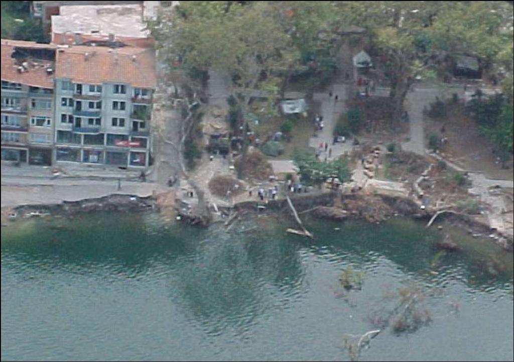
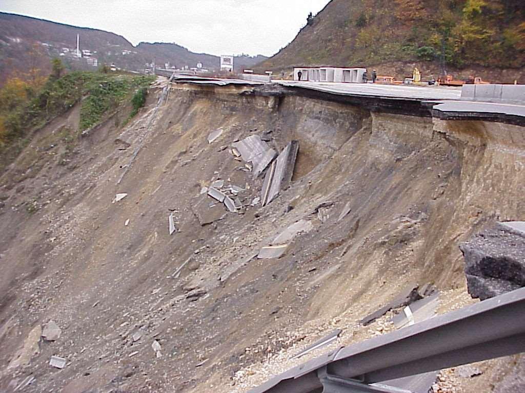
31 150 Düşey Gerilme Farkı (kpa) DYNAMIC SHEAR MODULUS (MPa) İZMİT ( Depth: m ) Elastic Threshold Plastic Threshold SHEAR MODULUS DAMPING RATIO DAMPING RATIO (%) SHEAR STRAIN, g (%)
32 Elastic threshold: Plastic threshold: g e = exp( 0.1PI) g p = PI 0.28 Cylic Behaviour: Elastic and Plastic threshold Thresholds are functions of Plasticity Index
33 Shear Strength Properties Shear Stress Amplitude Number of Cycles
34 GOLDEN HORN CLAY Normally consolidated, organic, fat clay (CH/OH) Uniform Cyclic Shear Stresses Static Shear Tests Following Uniform Cyclic Shear Stresses Uniform Cyclic Loading Under Sustained Shear Stresses Simultaneous Application of Cyclic and Static Shear Stresses
35 B O Ş LU K S U Y U B A S IN C I (k P a ) B İRİM K AYM A (% ) ÇEVRİM SAYISI
36 100 BEHAVIOUR DURING UNIFORM CYCLIC LOADING BİRİM KAYMA (%) , ÇEVRİM SAYISI Cyclic Shear Stress Ratio - Shear Strain Amplitude Relationship cyclic yield strength for different number of cycles
37 TEKRARLI KAYMA GERİLMESİ ORANI 0,9 0,8 0,7 0,6 0,5 0,4 0,3 0, ,5 1 1,5 2 2,5 3 BİRİM KAYMA (%)


38 PORE PRESSURE RATIO SHEAR STRAIN 0.5 CYCLIC STRESS RATIO Golcuk N=1 N=5 N=10 N= AXIAL STRAIN (%)
39 Shear Strength Ratio = Post Cyclic Shear Strength = Static Undrained Shear Strength Cyclic Shear Strain Ratio = Maximum Shear Strain Amplitude = Failure Strain in Static Shear Test
40 1.1 CYCLIC SHEAR STRESS RATIO N = 8 cycles 0.8 N = 25 cycles 0.7 N = 60 cycles 0.6 Cyclic strain threshold N = 25 CYCLES CRITICAL SHEAR STRAIN RATIO CYCLIC SHEAR STRAIN RATIO
41


42 AXIAL STRAIN (%) N = 20 N = 30 N = 40 before cyclic loading post cyclic loading AXIAL STRESS (kpa)
43 POST EARTHQUAKE BEHAVIOUR Decrease in Effective Stresses Particle Structure Breakdown Softening Shear Strength Reduction Additional Settlements
44 Soil Layers modify Earthquake Characteristics and Earthquake Excitations modify Engineering Characteristics of Soil Layers
45 0 PLASTİSİTE İNDİSİ (%) DİNAMİK KAYMA MODÜLÜ (MPa) DERİNLİK (m) DERİNLİK (m)
46 Axial Stress (kp a) LL = 65 PI = 36 (CH) N(Number of Cycles) GÖLCÜK, 6.0 m LL= 68 PI = 35 (CH) LL= 38 PI = 13 (CL) 20 m ZEYTİNBURNU 70m
47 DİNAMİK KAYMA MODÜLÜ (MPa) STATİK KAYMA GERİLMESİ OLMADAN STATİK KAYMA GERİLMESİ ALTINDA 0,01 0, TEKRARLI BİRİM KAYMA GENLİĞİ (%)
 60 50 40 30 20 Numune özellikler: AKO=1-1.5 w=%26-51 PI=%10-33 sc=70-400 kpa (çevre basıncı) 10 0 0 10 20 30 40 50 60 70 80 90 100 Likit limit, LL (%)")
48 Çalışmada Okur, Ansal (2000); Okur, Ansal (2001) çalışmalarına ek olarak 21 sondaj kuyusundan alınan örselenmemiş numuneler kullanılmıştır Plastisite indisi, PI (%) Numune özellikler: AKO=1-1.5 w=%26-51 PI=%10-33 sc= kpa (çevre basıncı) Likit limit, LL (%)
49 Kayma modülü oranı, G/G maks 1,2 1 0,8 0,6 0,4 0,2 SB1 N= Sönüm oranı, D (%) 0 0 0,0001 0,001 0,01 0, Birim kayma genliği, g(%) 0,015 SB1 Tekrarlı gerilme oranı genliği, d /2 c 0,01 0, ,005-0,01 N=10-15 G maks =34.8 Mpa G/G maks =%100 D=%2.82-0,015-0,004-0,003-0,002-0, ,001 0,002 0,003 0,004 0,005 Birim şekil değiştirme, e (%)
50 1,2 SB1 25 Kayma modülü oranı, G/G maks 1 0,8 0,6 0,4 0,2 N= Sönüm oranı, D (%) 0 0 0,0001 0,001 0,01 0, Birim kayma genliği, g(%) 0,06 SB1 Tekrarlı gerilme oranı, d /2 c 0,04 0,02 0-0,02-0,04 N=65-70 G=27.9 Mpa G/G maks =%82.1 D=%4.4-0,06-0,025-0,02-0,015-0,01-0, ,005 0,01 0,015 0,02 0,025 0,03 Birim şekil değiştirme e (%)
51 1,2 SB1 25 Kayma modülü oranı, G/G maks 1 0,8 0,6 0,4 0,2 N= Sönüm oranı, D (%) 0 0 0,0001 0,001 0,01 0, Birim kayma genliği, g(%) 0,5 0,4 SB1 Tekrarlı gerilme oranı, d/2 c 0,3 0,2 0,1 0-0,1-0,2-0,3 N= G=1.5 Mpa G/G maks =%5-3 D=% ,4-0, e (%)
52 0,1 0,08 Gerilme oranı genliği, d /2 c 0,06 0,04 0,02 0-0,02-0,04-0,06-0,08-0,1 0, Ç evrim sayısı, N 0,06 Boşluk suyu basıncı oranı, u/ c 0,05 0,04 0,03 0,02 0, Ç evrim sayısı, N
53 1,2 Y8 PI:28 A 1 C B E 0,8 G/Gmaks 0,6 G D 0,4 F 0,2 0 0,0001 0,001 0,01 0,1 1 g(%)
54 FIELD TESTS Low-strain tests: Seismic Reflection / Refraction Test Seismic Cross-Hole / Down-Hole / Up-Hole Test Steady-State Vibration (Rayleigh Wave) Test Spectral Analysis of Surface Waves (SASW) Suspension PS Logging Seismic Cone Penetration Test (SCPT) High-strain element test: Standard Penetration Test, SPT Cone Penetration Test, CPT Dilatometer Test, DMT Pressuremeter Test, PMT
55 Measurement of Dynamic Soil Properties Laboratory methods involve testing small specimens of soil samples (~38-70 mm in diameter ) that are assumed to be representative of the soil in the field. Field methods involve testing soil in place by measuring seismic wave propagation Factors such as testing procedure, testing errors and interpretation errors effects measurements. Laboratory Testing Methods (+) Pros. conditions can be controlled wide range of strains can do parametric studies Field Testing Methods (+) Pros. properties measured in existing state do not require sampling testing relatively large volume of soil (-) Cons. sample disturbance specimen size reproduction of actual field conditions (stress, chemical, thermal and structural) (-) Cons. conditions cannot be controlled indirect measurement limited strain range
 Quantifies penetration resistance of soils Provides")
 split-spoon sampler is driven into the undisturbed soil")
 until 18-in penetration is achieved.")
 of penetration is recorded seperately.")
 of driving is reported as the SPT result at that depth (N")
56 Field Testing in Geotechnical Engineering Standard Penetration Test (SPT) Quantifies penetration resistance of soils Provides some correlation with in-place (in-situ) soil properties 2-in. (51mm) split-spoon sampler is driven into the undisturbed soil by using 140-lb(63.6kg) weight falling 30 in. (0.76m) until 18-in penetration is achieved. Blow counts for driving the sample for each 6-in. (152mm) of penetration is recorded seperately. Number of blow counts required for the last 12-in (0.3m) of driving is reported as the SPT result at that depth (N SPT ) Repeat at regular depth intervals (typically 1-2m) to obtain N SPT with depth.

57 Standard Penetration Test (SPT) 0 N 1,60, bpf SPT Borehole D1 SPT Borehole D2 Depth, ft GWL shale
58 Standard Penetration Test (SPT) Need to apply corrections to N SPT to have a standardized value (N 1,60 ) Corrected N 1,60 values are calculated as N 1,60 = N C N C R C S C B C E C N N = measured standard penetration resistance, C N = factor to normalize N to a reference effective overburden stress, C R = correction for rod length, C S = correction for non-standardized sampler configuration, C B = correction for borehole diameter, C E = correction for hammer energy ratio.
59 Correlations between shear wave velocity, VS and NSPT
60 Cone Penetration Test (CPT) Quantifies penetration resistance of soils Provides some correlation with in-situ soil properties A cylindrical probe with a cone-shaped tip with different sensors that allow real-time continuous measurements by pushing it into the ground at a speed of 2 cm/s. Measures: 1. cone resistance, q c at the tip 2. the sleeve friction, f s 3. pore water pressure, u Field computer displays the data in real-time and stores it at regular depth intervals.


61 Field Site CPT Profile, May 2006

62 Cone Penetration Test (CPT) Identification and classification of soil layers
63 Cone Penetration Test (CPT) Advantages Fast method, Gives detailed profiles, Relatively cheap, A lot of correlations exist, Allows measurements at in situ conditions, avoiding problems relating to sample disturbance. Limitations Only usable in soft to medium stiff materials without boulders, No samples are obtained for visual examination and laboratory testing.
64 PENETRATION TESTS SPT SPT-N Shear Wave Velocity CPT Point resistance Shear Wave Velocity Vs = 51.5N Vs = 55.3qc (İYİSAN, 1996)
65 Wave Propagation and Geophysical Methods Seismic Test Method in General 1. Creation of transient and/or steady state stress waves using an energy source 2. Monitoring of particle motion with transducers (i.e. receivers) located at one or more locations away from the source 3. Times of wave arrivals are determined from the waveforms recorded at receiver locations and wave velocity is calculated from V = Dx / Dt should take into account: The size of the receivers that are used to monitor wave motions should be much smaller than the wavelength Receivers should be at least two to four wavelengths away from the source

66 Seismic Reflection Test Useful for investigation of large-scale and/or very deep stratigraphy Many source and receiver locations must be used to produce meaningful images Interference between the reflected waves and surface waves requires careful signal processing and usually restrict the use of this method at shallow-depths
67 Seismic Refraction Test An active source and a series of receivers are placed on the ground surface in a linear array Output of all receivers are recorded when the source is triggered Arrival times of the first waves to reach each receiver is determined and plotted as a function of source-receiver distance The method is based on the ability to detect the arrival of wave energy that is critically refracted ( traveling parallel to the boundary) from a higher velocity layer which underlies lower velocity sediment.


68 Spectral-Analysis-of-Surface-Waves-Test (SASW) Rayleigh wave energy is created at one point and resulting vertical surface motions at two or more measurement points (receiver points) away from the source are monitored. Measurements are performed at multiple source-receiver spacings along a linear array placed on the ground surface.
69 Spectral-Analysis-of-Surface-Waves-Test (SASW) Variation of V R with different l or f is called the dispersion curve An initial estimate of the V s profile is made and iteratively changed to match the theoretical dispersion curve with the experimental dispersion curve to obtain the best estimate for Vs profile Shear Wave Velocity (fps) Best-Fit Profile for Line A Best-Fit Profile for Line B Depth (ft) GWL shale 45
70 Spectral-Analysis-of-Surface-Waves-Test (SASW) Advantages Quick and easy to perform Does not require drilling Can measure V s profile up to 100 m depth Limitations Resolution decreases with depth Thin layers are hard to detect Provides global measurements Determines averaged properties over the lateral measurement distance

71 Crosshole Seismic Test (CST) Source and receivers are placed at the same depth in adjacent boreholes. P and S waves are generated using the source mechanism and waves propagating along horizontal path are measured at the receiver boreholes. Travel time from the source to receivers (direct travel time) and the travel time between the receivers (interval travel time) are measured. By testing at various depths variation of velocity with depth is obtained.
 A wedged source is used to generate P and S waves at")

72 Crosshole Seismic Test (CST) Geophone Trigger Air Piston to Operate Wedging Mechanism Expandable Wedge which Engages the Casing Sliding Hammer (moves vertically) A wedged source is used to generate P and S waves at depth inside the source borehole, The wedging mechanism operates with compressed air to lock the hammer against the casing in the borehole, A sliding hammer that moves vertically produces impulses of reversed polarity.
73 Crosshole Seismic Test (CST) Wave propagation velocities are calculated from difference in arrival times at adjacent pairs of boreholes Arrival times can be determined by eye using points of common phase (first arrival, first peak, first trough)
74 Field Measurement of Dynamic Soil Properties Crosshole Seismic Test (CST) Advantages Resolution is high since source and receivers are placed close to the material to be evaluated Direct measurement of wave velocities are performed Individual soil layers can be tested Can detect thin layers Reliable data up to 100 m Limitations Requires two or three boreholes, expensive and time consuming Requires vertical deviation survey for the boreholes Provides local measurements

75 Downhole Seismic Test (DST) An impulse source is located on the ground adjacent to a single borehole and one or more receivers are placed in the borehole. P and S waves are generated from the source on the surface and waves propagating along a direct path between the source and the receivers are measured. Travel time from the source to receivers (direct travel time) and the travel time between the receivers (interval travel time) are measured Travel distances are typically based on assuming straight ray paths between the source and the receivers. By testing at various depths variation of velocity with depth is obtained.
76 Field Measurement of Dynamic Soil Properties Downhole Seismic Test (DST) A plot of travel time with depth can be generated using the arrival times identified on the waveforms recorded at various depths Slope of travel-time curve at any depth represents the wave propagation velocity at that depth

77 Seismic Cone Penetration Test (SCPT) A cone penetrometer that measures tip and side resistances on a probe pushed into the soil that allows measurement of shear wave velocitoes ina downhole testing arrangement. SH waves are generated at the surface near the insertion point of the cone by applying a horizontal impact on an embedded beam and travel times of the shear wave energy are measured at one or more locations above the cone tip. Travel time-depth curves can be generated and interpreted in the same way as for downhole tests. By testing at various depths variation of velocity with depth is obtained.
78 Downhole Seismic Test (DST) Advantages Direct measurement of wave velocities are performed Reliable data up to 50 m Less expensive than CST (requires one borehole) Limitations Energy that can be generated by the source on the ground surface limits the testing depth Provides local measurements

79 PS-Logging Test Measurements are made in a single, cased/uncased fluid-filled borehole. An acoustic wave is generated in the borehole fluid by activating a solenoid source which is located at the end of the suspending probe. The impact of this wave on the borehole wall creates both P and S waves which travel radially away from the borehole. A portion of the wave energy travels along the soil as a head wave and transmits energy back into the fluid. These waves are detected with two 2-D geophones on the probe. The vertical and horizontal components of the geophone correspond to P- and S-wave energies, respectively. By testing at various depths variation of velocity with depth is obtained.


80 PS-Logging Test The travel time differences between horizontal and vertical receivers of the two 2-D geophones on the probe are used to calculate the interval S- and P-wave velocities, respectively, over the 1-m interval. The results of a suspension logging test consist of a Vs and a Vp profile, with data points as many as measurement intervals.
81 PS-Logging Test Advantages Effective at greater depths (up to 1 km) Source travels with the receivers down the borehole Limitations Frequencies generated by the source are too high (500to 2000Hz for S wave) Indirect measurement of S waves Can be significantly effected from grouting around the casing
82 Comparison of CST, DST and PS 0.00 S5 Silty Clay N=20 I p =% 41 S12 V s (m/s) Silty Sand / Sandstone N> Siltstone/Sandstone Claystone CH DH PS m
Soil Behaviour in Earthquake Geotechnics
 Soil Behaviour in Earthquake Geotechnics KENJI ISHIHARA Department of Civil Engineering Science University of Tokyo This publication was supported by a generous donation from the Daido Life Foundation
3 DYNAMIC SOIL PROPERTIES
 Module 3 DYNAMIC SOIL PROPERTIES (Lectures 10 to 16) Lecture 13 Topics 3.3.18 Other field tests 3.3.19 Laboratory tests 3.3.20 Sampling 3.3.21 Low-Strain element tests Resonant column test Ultrasonic pulse
Geophysical Site Investigation (Seismic methods) Amit Prashant Indian Institute of Technology Gandhinagar
 Amit Prashant Indian Institute of Technology Gandhinagar") Geophysical Site Investigation (Seismic methods) Amit Prashant Indian Institute of Technology Gandhinagar Short Course on Geotechnical Aspects of Earthquake Engineering 04 08 March, 2013 Seismic Waves
Geophysical Site Investigation (Seismic methods) Amit Prashant Indian Institute of Technology Gandhinagar Short Course on Geotechnical Aspects of Earthquake Engineering 04 08 March, 2013 Seismic Waves
Boreholes. Implementation. Boring. Boreholes may be excavated by one of these methods: 1. Auger Boring 2. Wash Boring 3.
 Implementation Boreholes 1. Auger Boring 2. Wash Boring 3. Rotary Drilling Boring Boreholes may be excavated by one of these methods: 4. Percussion Drilling The right choice of method depends on: Ground
Conventional Field Testing & Issues (SPT, CPT, DCPT, Geophysical methods)
") Conventional Field Testing & Issues (SPT, CPT, DCPT, Geophysical methods) Ajanta Sachan Assistant Professor Civil Engineering IIT Gandhinagar Conventional Field Testing 1 Field Test: In-situ shear strength
Conventional Field Testing & Issues (SPT, CPT, DCPT, Geophysical methods) Ajanta Sachan Assistant Professor Civil Engineering IIT Gandhinagar Conventional Field Testing 1 Field Test: In-situ shear strength
VMS-GeoMil. Background
 Background When using a drilling rig for cone penetration testing, a mechanical clamp can be mounted to the drilling head (by means of a special transition piece). The depth than can be achieved depends
GEOTECHNICAL SITE CHARACTERIZATION
 GEOTECHNICAL SITE CHARACTERIZATION Neil Anderson, Ph.D. Professor of Geology and Geophysics Richard W. Stephenson, P.E., Ph.D. Professor of Civil, Architectural and Environmental Engineering University
Cone Penetration Testing in Geotechnical Practice
 Cone Penetration Testing in Geotechnical Practice Table Of Contents: LIST OF CONTENTS v (4) PREFACE ix (2) ACKNOWLEDGEMENTS xi (1) SYMBOL LIST xii (4) CONVERSION FACTORS xvi (6) GLOSSARY xxii 1. INTRODUCTION
Chapter 12 Subsurface Exploration
 Page 12 1 Chapter 12 Subsurface Exploration 1. The process of identifying the layers of deposits that underlie a proposed structure and their physical characteristics is generally referred to as (a) subsurface
IN SITU TESTING TECHNOLOGY FOR FOUNDATION & EARTHQUAKE ENGINEERING. Wesley Spang, Ph.D., P.E. AGRA Earth & Environmental, Inc.
 IN SITU TESTING TECHNOLOGY FOR FOUNDATION & EARTHQUAKE ENGINEERING Wesley Spang, Ph.D., P.E. AGRA Earth & Environmental, Inc. Portland, Oregon In situ testing of soil, which essentially consists of evaluating
Resonant Column and Torsional Cyclic Shear System
 Resonant Column and Torsional Cyclic Shear System Combined Resonant Column (RC) & Torsional Cyclic Shear (TCS) Test apparatus to determinate with saturated soil : Shear Modulus Damping Modulus versus Shear
Soil Properties - II
 Soil Properties - II Amit Prashant Indian Institute of Technology andhinagar Short Course on eotechnical Aspects of Earthquake Engineering 04 08 March, 2013 Seismic Waves Earthquake Rock Near the ground
This document downloaded from vulcanhammer.net vulcanhammer.info Chet Aero Marine
 This document downloaded from vulcanhammer.net vulcanhammer.info Chet Aero Marine Don t forget to visit our companion site http://www.vulcanhammer.org Use subject to the terms and conditions of the respective
Source Wave Design for Downhole Seismic Testing
 Source Wave Design for Downhole Seismic Testing Downhole seismic testing (DST) has become a very popular site characterizing tool among geotechnical engineers. DST methods, such as the Seismic Cone Penetration
Manual on Subsurface Investigations National Highway Institute Publication No. FHWA NHI Federal Highway Administration Washington, DC
 Manual on Subsurface Investigations National Highway Institute Publication No. FHWA NHI-01-031 Federal Highway Administration Washington, DC Geotechnical Site Characterization July 2001 by Paul W. Mayne,
Module 3. DYNAMIC SOIL PROPERTIES (Lectures 10 to 16)
") Module 3 DYNAMIC SOIL PROPERTIES (Lectures 10 to 16) Lecture 15 Topics 3.6 STRESS-STRAIN BEHAVIOR OF CYCLICALLY LOADED SOILS 3.7 SOME BASIC ASPECTS OF PARTICULATE MATTER BEHAVIOR 3.8 EQUIVALENT LINEAR
Module 3 DYNAMIC SOIL PROPERTIES (Lectures 10 to 16) Lecture 15 Topics 3.6 STRESS-STRAIN BEHAVIOR OF CYCLICALLY LOADED SOILS 3.7 SOME BASIC ASPECTS OF PARTICULATE MATTER BEHAVIOR 3.8 EQUIVALENT LINEAR
A Study on Dynamic Properties of Cement-Stabilized Soils
 A Study on Dynamic Properties of Cement-Stabilized Soils Pei-Hsun Tsai, a and Sheng-Huoo Ni 2,b Department of Construction Engineering, Chaoyang University of Technology, 68 Jifong E. Rd., Wufong District,
LECTURE 10. Module 3 : Field Tests in Rock 3.6 GEOPHYSICAL INVESTIGATION
 LECTURE 10 3.6 GEOPHYSICAL INVESTIGATION In geophysical methods of site investigation, the application of the principles of physics are used to the study of the ground. The soil/rock have different characteristics
EVALUATION OF STRENGTH OF SOILS AGAINST LIQUEFACTION USING PIEZO DRIVE CONE
 4 th International Conference on Earthquake Geotechnical Engineering June 25-28, 2007 Paper No. 1146 EVALUATION OF STRENGTH OF SOILS AGAINST LIQUEFACTION USING PIEZO DRIVE CONE Shun-ichi Sawada 1 ABSTRACT
Mechanical Wave Measurements. Electromagnetic Wave Techniques. Geophysical Methods GEOPHYSICAL SITE CHARACTERIZATION. Mechanical Wave Geophysics
 Geophysical Methods GEOPHYSICAL SITE CHARACTERIZATION Mechanical Wave Measurements Electromagnetic Wave Techniques Mechanical Wave Measurements Crosshole Tests (CHT) Downhole Tests (DHT) Spectral Analysis
Cyclic Behavior of Sand and Cyclic Triaxial Tests. Hsin-yu Shan Dept. of Civil Engineering National Chiao Tung University
 Cyclic Behavior of Sand and Cyclic Triaxial Tests Hsin-yu Shan Dept. of Civil Engineering National Chiao Tung University Causes of Pore Pressure Buildup due to Cyclic Stress Application Stress are due
SHEAR STRENGTH OF SOIL
 SHEAR STRENGTH OF SOIL Necessity of studying Shear Strength of soils : Soil failure usually occurs in the form of shearing along internal surface within the soil. Shear Strength: Thus, structural strength
Enhanced In-Situ Testing for Geotechnical Site Characterization. Graduate Course CEE 6423
 Enhanced In-Situ Testing for Geotechnical Site Characterization SPT, VST, DMT, PMT, CHT, DHT, CPT Graduate Course CEE 6423 Paul W. Mayne, PhD, P.E. Professor, Geosystems Program Civil & Environmental Engineering
CPT Applications - Liquefaction 2
 CPT Applications - Liquefaction 2 Peter K. Robertson CPT in Geotechnical Practice Santiago, Chile July, 2014 Definitions of Liquefaction Cyclic (seismic) Liquefaction Zero effective stress (during cyclic
SHEAR STRENGTH OF SOIL
 Soil Failure Criteria SHEAR STRENGTH OF SOIL Knowledge about the shear strength of soil important for the analysis of: Bearing capacity of foundations, Slope stability, Lateral pressure on retaining structures,
SOME OBSERVATIONS RELATED TO LIQUEFACTION SUSCEPTIBILITY OF SILTY SOILS
 SOME OBSERVATIONS RELATED TO LIQUEFACTION SUSCEPTIBILITY OF SILTY SOILS Upul ATUKORALA 1, Dharma WIJEWICKREME 2 And Norman MCCAMMON 3 SUMMARY The liquefaction susceptibility of silty soils has not received
Soil strength. the strength depends on the applied stress. water pressures are required
 Soil Strength Soil strength u Soils are essentially frictional materials the strength depends on the applied stress u Strength is controlled by effective stresses water pressures are required u Soil strength
Soil and Rock Strength. Chapter 8 Shear Strength. Steel Strength. Concrete Strength. Dr. Talat Bader May Steel. Concrete.
 Chapter 8 Shear Strength Dr. Talat Bader May 2006 Soil and Rock Strength Unconfined compressive strength (MPa) Steel Concrete 20 100 250 750 0.001 0.01 Soil 0.1 1.0 10 Rock 100 250 F y = 250 to 750 MPa
Deep Foundations 2. Load Capacity of a Single Pile
 Deep Foundations 2 Load Capacity of a Single Pile All calculations of pile capacity are approximate because it is almost impossible to account for the variability of soil types and the differences in the
Evaluation of soil liquefaction using the CPT Part 2
 Evaluation of soil liquefaction using the CPT Part 2 P.K. Robertson 2013 Definitions of Liquefaction Cyclic (seismic) Liquefaction Zero effective stress (during cyclic loading) Flow (static) Liquefaction
Table 3. Empirical Coefficients for BS 8002 equation. A (degrees) Rounded Sub-angular. 2 Angular. B (degrees) Uniform Moderate grading.
 Rounded Sub-angular. 2 Angular. B (degrees) Uniform Moderate grading.") Hatanaka and Uchida (1996); ' 20N 20 12N 20 ' 45 A lower bound for the above equation is given as; 12N 15 ' 45 Table 3. Empirical Coefficients for BS 8002 equation A Angularity 1) A (degrees) Rounded 0
Hatanaka and Uchida (1996); ' 20N 20 12N 20 ' 45 A lower bound for the above equation is given as; 12N 15 ' 45 Table 3. Empirical Coefficients for BS 8002 equation A Angularity 1) A (degrees) Rounded 0
Evaluation of liquefaction resistance of non-plastic silt from mini-cone calibration chamber tests
 Evaluation of liquefaction resistance of non-plastic silt from mini-cone calibration chamber tests C.D.P. Baxter, M.S. Ravi Sharma, N.V. Seher, & M. Jander University of Rhode Island, Narragansett, USA
Prof. B V S Viswanadham, Department of Civil Engineering, IIT Bombay
 56 Module 4: Lecture 7 on Stress-strain relationship and Shear strength of soils Contents Stress state, Mohr s circle analysis and Pole, Principal stressspace, Stress pathsin p-q space; Mohr-Coulomb failure
Dynamic properties and liquefaction potential of soils
 Dynamic properties and liquefaction potential of soils T. G. Sitharam*, L. GovindaRaju and A. Sridharan Department of Civil Engineering, Indian Institute of Science, Bangalore 560 012, India Design of
 UNIT I SITE INVESTIGATION AND SELECTION OF FOUNDATION Types of boring 1.Displacement borings It is combined method of sampling & boring operation. Closed bottom sampler, slit cup, or piston type is forced
1.8 Unconfined Compression Test
 1-49 1.8 Unconfined Compression Test - It gives a quick and simple measurement of the undrained strength of cohesive, undisturbed soil specimens. 1) Testing method i) Trimming a sample. Length-diameter
Hydrogeophysics - Seismics
 Hydrogeophysics - Seismics Matthias Zillmer EOST-ULP p. 1 Table of contents SH polarized shear waves: Seismic source Case study: porosity of an aquifer Seismic velocities for porous media: The Frenkel-Biot-Gassmann
This is what we will talk about today.
 This is what we will talk about today. 1. INTRODUCTION 2. SINGLE DEGREE OF FREEDOM, DAMPED, FORCED SYSTEMS 3. FOUNDATIONS ON ELASTIC SOILS 4. WAVE TRANSMISSION, ATTENUATION, AND ISOLATION 5. EVALUATION
Geotechnical Testing Methods I
 Geotechnical Testing Methods I Ajanta Sachan Assistant Professor Civil Engineering IIT Gandhinagar Hiding World of Geotechnical Engg!! Foundations Shoring Tunneling Soil Exploration Geotechnical Engg Structures
Laboratory Testing Total & Effective Stress Analysis
 SKAA 1713 SOIL MECHANICS Laboratory Testing Total & Effective Stress Analysis Prepared by: Dr. Hetty Mohr Coulomb failure criterion with Mohr circle of stress 2 ' 2 ' ' ' 3 ' 1 ' 3 ' 1 Cot Sin c ' ' 2
Evaluation of soil liquefaction using the CPT Part 1
 Evaluation of soil liquefaction using the CPT Part 1 Dr. Peter K. Robertson Webinar #7 2013 CPT Guide 5 th Edition Download FREE copy from: Robertson & Cabal (Robertson) 5 th Edition 2012 www.greggdrilling.com
8.1. What is meant by the shear strength of soils? Solution 8.1 Shear strength of a soil is its internal resistance to shearing stresses.
 8.1. What is meant by the shear strength of soils? Solution 8.1 Shear strength of a soil is its internal resistance to shearing stresses. 8.2. Some soils show a peak shear strength. Why and what type(s)
A COMPARISON BETWEEN IN SITU AND LABORATORY MEASUREMENTS OF PORE WATER PRESSURE GENERATION
 13 th World Conference on Earthquake Engineering Vancouver, B.C., Canada August 1-6, 2004 Paper No. 1220 A COMPARISON BETWEEN IN SITU AND LABORATORY MEASUREMENTS OF PORE WATER PRESSURE GENERATION Kenan
B-1 BORE LOCATION PLAN. EXHIBIT Drawn By: 115G BROOKS VETERINARY CLINIC CITY BASE LANDING AND GOLIAD ROAD SAN ANTONIO, TEXAS.
 N B-1 SYMBOLS: Exploratory Boring Location Project Mngr: BORE LOCATION PLAN Project No. GK EXHIBIT Drawn By: 115G1063.02 GK Scale: Checked By: 1045 Central Parkway North, Suite 103 San Antonio, Texas 78232
LABORATORY MEASUREMENTS OF STIFFNESS OF SOFT CLAY USING BENDER ELEMENTS
 LABORATORY MEASUREMENTS OF STIFFNESS OF SOFT CLAY USING BENDER ELEMENTS ABSTRACT: S. H. Oh 1, D. S. Park 2, B. J. Kim 3, E. J. Kim 1 and Y. J. Mok 4 1 Research Assistant, Dept. of Civil Eng., Kyunghee
Theory of Shear Strength
 MAJ 1013 ADVANCED SOIL MECHANICS Theory of Shear Strength Prepared by, Dr. Hetty 1 Strength of different materials Steel Concrete Soil Tensile strength Compressive strength Shear strength Complex behavior
MEDAT-2: Some Geotechnical Opportunities. Site Characterization -- Opportunities. Down-hole CPT & vane (Fugro)
") MEDAT-2: Some Geotechnical Opportunities Ross W. Boulanger Department of Civil & Environmental Engineering University of California Davis, California 95616-5294 rwboulanger@ucdavis.edu Presentation for
MEDAT-2: Some Geotechnical Opportunities Ross W. Boulanger Department of Civil & Environmental Engineering University of California Davis, California 95616-5294 rwboulanger@ucdavis.edu Presentation for
Design Procedures For Dynamically Loaded Foundations
 Design Procedures For Dynamically Loaded Foundations 1/11 Choice of parameters for equivalent lumped systems Lumped mass : the mass of the foundation and supported machinery Damping : 1 Geometrical(or
Investigation of Liquefaction Behaviour for Cohesive Soils
 Proceedings of the 3 rd World Congress on Civil, Structural, and Environmental Engineering (CSEE 18) Budapest, Hungary April 8-10, 2018 Paper No. ICGRE 134 DOI: 10.11159/icgre18.134 Investigation of Liquefaction
Small-Strain Stiffness and Damping of Soils in a Direct Simple Shear Device
 Small-Strain Stiffness and Damping of Soils in a Direct Simple Shear Device B. D Elia, G. Lanzo & A. Pagliaroli Dipartimento di Ingegneria Strutturale e Geotecnica, Università di Roma La Sapienza, Italy.
Shear Wave Velocity Comparisons; Surface Wave, Downhole and SCPT Measurement Methods - A Case History
 Shear Wave Velocity Comparisons; Surface Wave, Downhole and SCPT Measurement Methods - A Case History M.R. Lewis & J. Clemente Bechtel Corporation, California, USA I.A. Weemees ConeTec, Inc., British Columbia,
Chapter 5 Shear Strength of Soil
 Page 5 Chapter 5 Shear Strength of Soil. The internal resistance per unit area that the soil mass can offer to resist failure and sliding along any plane inside it is called (a) strength (b) shear strength
Cite this paper as follows:
 Cite this paper as follows: Naughton P.J. and O Kelly B.C. 2001. An overview of the University College Dublin hollow cylinder apparatus. Proceedings of the 14th Young European Geotechnical Engineer s Conference,
From - To 0,00-4,90 4,90-6,40 6,40-8,60 8,60-9,60 9,60-10,50 10,50-12,00 12,00-14,80 14,80-15,80 15,80-19,30 19, ,00
 Závěrka 12,Praha 6,169 00 Log of Boring BH1 Project ID: 2018_A-017 Annex no.: A.1G Drilling equipment: Hütte 202 TF Location: Prague 12 Overall depth: 2 m Borehole position: Date start: 22.11.2017 Foreman:
CPT Data Interpretation Theory Manual
 CPT Data Interpretation Theory Manual 2016 Rocscience Inc. Table of Contents 1 Introduction... 3 2 Soil Parameter Interpretation... 5 3 Soil Profiling... 11 3.1 Non-Normalized SBT Charts... 11 3.2 Normalized
Dynamic Analysis Contents - 1
 Dynamic Analysis Contents - 1 TABLE OF CONTENTS 1 DYNAMIC ANALYSIS 1.1 Overview... 1-1 1.2 Relation to Equivalent-Linear Methods... 1-2 1.2.1 Characteristics of the Equivalent-Linear Method... 1-2 1.2.2
Chapter (12) Instructor : Dr. Jehad Hamad
 Instructor : Dr. Jehad Hamad") Chapter (12) Instructor : Dr. Jehad Hamad 2017-2016 Chapter Outlines Shear strength in soils Direct shear test Unconfined Compression Test Tri-axial Test Shear Strength The strength of a material is the
Chapter (12) Instructor : Dr. Jehad Hamad 2017-2016 Chapter Outlines Shear strength in soils Direct shear test Unconfined Compression Test Tri-axial Test Shear Strength The strength of a material is the
SURFACE WAVE MODELLING USING SEISMIC GROUND RESPONSE ANALYSIS
 43 SURFACE WAVE MODELLING USING SEISMIC GROUND RESPONSE ANALYSIS E John MARSH And Tam J LARKIN SUMMARY This paper presents a study of surface wave characteristics using a two dimensional nonlinear seismic
Case Study - Undisturbed Sampling, Cyclic Testing and Numerical Modelling of a Low Plasticity Silt
 6 th International Conference on Earthquake Geotechnical Engineering 1-4 November 2015 Christchurch, New Zealand Case Study - Undisturbed Sampling, Cyclic Testing and Numerical Modelling of a Low Plasticity
Behavior of Soft Riva Clay under High Cyclic Stresses
 Behavior of Soft Riva Clay under High Cyclic Stresses Mustafa Kalafat Research Assistant, Boğaziçi University, Istanbul, Turkey; mkalafat@boun.edu.tr Canan Emrem, Ph.D., Senior Engineer, ZETAS Zemin Teknolojisi
Station Description Sheet GRA
 Station Description Sheet GRA 1. General Information 2. Geographical Information / Geomorphology 3. Geological Information 4. Geotechnical Site Characterization 5. Geophysical Site Characterization 6.
Soils. Technical English - I 10 th week
 Technical English - I 10 th week Soils Soil Mechanics is defined as the branch of engineering science which enables an engineer to know theoretically or experimentally the behavior of soil under the action
SITE INVESTIGATION 1
 SITE INVESTIGATION 1 Definition The process of determining the layers of natural soil deposits that will underlie a proposed structure and their physical properties is generally referred to as site investigation.
LIQUEFACTION RESISTANCE OF SILTYSAND BASED ON LABORATORY UNDISTURBED SAMPLE AND CPT RESULTS
 3 th World Conference on Earthquake Engineering Vancouver, B.C., Canada August -6, 24 Paper No. 75 LIQUEFACTION RESISTANCE OF SILTYSAND BASED ON LABORATORY UNDISTURBED SAMPLE AND CPT RESULTS Mehdi ESNA-ASHARI,
Interpretation of Flow Parameters from In-Situ Tests (P.W. Mayne, November 2001)
") Interpretation of Flow Parameters from In-Situ Tests (P.W. Mayne, November 2001) FLOW PROPERTIES Soils exhibit flow properties that control hydraulic conductivity (k), rates of consolidation, construction
Interpretation of Flow Parameters from In-Situ Tests (P.W. Mayne, November 2001) FLOW PROPERTIES Soils exhibit flow properties that control hydraulic conductivity (k), rates of consolidation, construction
NEW DOWN-HOLE PENETROMETER (DHP-CIGMAT) FOR CONSTRUCTION APPLICATIONS
 FOR CONSTRUCTION APPLICATIONS") NEW DOWN-HOLE PENETROMETER (DHP-CIGMAT) FOR CONSTRUCTION APPLICATIONS 1 2 C. Vipulanandan 1, Ph.D., M. ASCE and Omer F. Usluogullari 2 Chairman, Professor, Director of Center for Innovative Grouting Materials
NEW DOWN-HOLE PENETROMETER (DHP-CIGMAT) FOR CONSTRUCTION APPLICATIONS 1 2 C. Vipulanandan 1, Ph.D., M. ASCE and Omer F. Usluogullari 2 Chairman, Professor, Director of Center for Innovative Grouting Materials
Micro Seismic Hazard Analysis
 Micro Seismic Hazard Analysis Mark van der Meijde INTERNATIONAL INSTITUTE FOR GEO-INFORMATION SCIENCE AND EARTH OBSERVATION Overview Site effects Soft ground effect Topographic effect Liquefaction Methods
KDOT Geotechnical Manual Edition. Table of Contents
 KDOT Geotechnical Manual 2007 Edition The KDOT Geotechnical Manual is available two volumes. Both volumes are very large electronic (pdf) files which may take several minutes to download. The table of
Soil Dynamics Prof. Deepankar Choudhury Department of Civil Engineering Indian Institute of Technology, Bombay
 Soil Dynamics Prof. Deepankar Choudhury Department of Civil Engineering Indian Institute of Technology, Bombay Module - 4 Lecture 21 Dynamic Soil, Properties Estimation of Gmax, Modulus Reduction Curves,
Pre-failure Deformability of Geomaterials. Hsin-yu Shan Dept. of Civil Engineering National Chiao Tung University
 Pre-failure Deformability of Geomaterials Hsin-yu Shan Dept. of Civil Engineering National Chiao Tung University Strain Levels Strain at failure Sand Clay Rock Distribution of strain of soil in the field
Correlations between soil parameters and penetration testing results
 1 A 1 6 Correlations between soil parameters and penetration testing results Corrélation entre paramètres du sol et résultats de sondage J. FORMAZIN, Director, VEB SBK Wasserbau, KB Baugrund Berlin, Berlin,
 www.novotechsoftware.com The standard penetration test (SPT) is an in-situ dynamic penetration test designed to provide information on the geotechnical engineering properties of soil. The test procedure
SHEAR STRENGTH OF SOIL UNCONFINED COMPRESSION TEST
 SHEAR STRENGTH OF SOIL DEFINITION The shear strength of the soil mass is the internal resistance per unit area that the soil mass can offer to resist failure and sliding along any plane inside it. INTRODUCTION
DOWN-HOLE SEISMIC SURVEY AND VERTICAL ELECTRIC SOUNDINGS RABASKA PROJECT, LÉVIS, QUÉBEC. Presented to :
 DOWN-HOLE SEISMIC SURVEY AND VERTICAL ELECTRIC SOUNDINGS RABASKA PROJECT, LÉVIS, QUÉBEC Presented to : TERRATECH 455, René-Lévesque Blvd. West Montreal, Québec HZ 1Z3 Presented by : GEOPHYSICS GPR INTERNATIONAL
GEOTECHNICAL INVESTIGATION REPORT
 GEOTECHNICAL INVESTIGATION REPORT SOIL INVESTIGATION REPORT FOR STATIC TEST FACILITY FOR PROPELLANTS AT BDL, IBRAHIMPATNAM. Graphics Designers, M/s Architecture & Engineering 859, Banjara Avenue, Consultancy
Soil Behaviour Type from the CPT: an update
 Soil Behaviour Type from the CPT: an update P.K. Robertson Gregg Drilling & Testing Inc., Signal Hill, California, USA ABSTRACT: One of the most common applications of CPT results is to evaluate soil type
(Refer Slide Time: 02:18)
") Geology and Soil Mechanics Prof. P. Ghosh Department of Civil Engineering Indian Institute of Technology Kanpur Lecture 40 Shear Strength of Soil - C Keywords: Shear strength of soil, direct shear test,
Geology and Soil Mechanics Prof. P. Ghosh Department of Civil Engineering Indian Institute of Technology Kanpur Lecture 40 Shear Strength of Soil - C Keywords: Shear strength of soil, direct shear test,
ENCE 3610 Soil Mechanics. Site Exploration and Characterisation Field Exploration Methods
 ENCE 3610 Soil Mechanics Site Exploration and Characterisation Field Exploration Methods Geotechnical Involvement in Project Phases Planning Design Alternatives Preparation of Detailed Plans Final Design
Theory of Shear Strength
 SKAA 1713 SOIL MECHANICS Theory of Shear Strength Prepared by, Dr. Hetty 1 SOIL STRENGTH DEFINITION Shear strength of a soil is the maximum internal resistance to applied shearing forces The maximum or
Geotechnical Properties of Soil
 Geotechnical Properties of Soil 1 Soil Texture Particle size, shape and size distribution Coarse-textured (Gravel, Sand) Fine-textured (Silt, Clay) Visibility by the naked eye (0.05 mm is the approximate
Determining G-γ Degradation Curve in Cohesive Soils by Dilatometer and in situ Seismic Tests
 Determining G-γ Degradation Curve in Cohesive Soils by Dilatometer and in situ Seismic Tests Ivandic Kreso, Spiranec Miljenko, Kavur Boris, Strelec Stjepan Abstract This article discusses the possibility
EVALUATION OF DYNAMIC METHODS FOR EARTHWORK ASSESSMENT
 Vol. 11, Issue 1/, 38-44 DOI:./cee--000 EVALUATION OF DYNAMIC METHODS FOR EARTHWORK ASSESSMENT Jozef VLČEK 1,*, Dominika ĎUREKOVÁ 2, Katarína ZGÚTOVÁ 2 1 Department of Geotechnics, Faculty of Civil Engineering,
CYCLIC LIQUEFACTION POTENTIAL OF LACUS- TRINE CARBONATE SILT FROM JULIAN ALPS
 CYCLIC LIQUEFACTION POTENTIAL OF LACUS- TRINE CARBONATE SILT FROM JULIAN ALPS BOJAN ŽLENDER and STANISLAV LENART About the authors Bojan Žlender University of Maribor, Faculty of Civil Engineering Smetanova
Table of Contents Chapter 1 Introduction to Geotechnical Engineering 1.1 Geotechnical Engineering 1.2 The Unique Nature of Soil and Rock Materials
 Table of Contents Chapter 1 Introduction to Geotechnical Engineering 1.1 Geotechnical Engineering 1.2 The Unique Nature of Soil and Rock Materials 1.3 Scope of This Book 1.4 Historical Development of Geotechnical
Shear Strength of Soils
 Shear Strength of Soils Soil strength Most of problems in soil engineering (foundations, slopes, etc.) soil withstands shear stresses. Shear strength of a soil is defined as the capacity to resist shear
Shear Strength of Soil
 8 Shear Strength of Soil 8 1 INTRODUCTION As a structural member, a piece of steel is capable of resisting compression, tension, and shear. Soil, however, like concrete and rock, is not capable of resisting
CHARACTERISING THE NON LINEARITIES OF LACUSTRINE CLAYS IN THE GRENOBLE BASIN
 Third International Symposium on the Effects of Surface Geology on Seismic Motion Grenoble, France, 30 August - September 2006 Paper Number: 8 CHARACTERISING THE NON LINEARITIES OF LACUSTRINE CLAYS IN
ISC 5 SELF-BORING PRESSUREMETER TESTS AT THE NATIONAL FIELD TESTING FACILITY, BALLINA 5 9 SEPT 2016
 ISC 5 5 9 SEPT 2016 SELF-BORING PRESSUREMETER TESTS AT THE NATIONAL FIELD TESTING FACILITY, BALLINA Fillippo Gaone James Doherty Susan Gourvenec Centre for Offshore Foundation Systems, UWA School of Civil,
Liquefaction and Foundations
 Liquefaction and Foundations Amit Prashant Indian Institute of Technology Gandhinagar Short Course on Seismic Design of Reinforced Concrete Buildings 26 30 November, 2012 What is Liquefaction? Liquefaction
Lateral impact loading and snap-back testing to estimate linear and nonlinear dynamic response of near-shore piles
 2th IMEKO TC4 International Symposium and 18th International Workshop on ADC Modelling and Testing Research on Electric and Electronic Measurement for the Economic Upturn Benevento, Italy, September 15-17,
Gotechnical Investigations and Sampling
 Gotechnical Investigations and Sampling Amit Prashant Indian Institute of Technology Gandhinagar Short Course on Geotechnical Investigations for Structural Engineering 12 14 October, 2017 1 Purpose of
Field measurement of shear wave velocity of soils
 GeoEdmonton08/GéoEdmonton2008 Field measurement of shear wave velocity of soils Fanyu Zhu, K.R. Peaker and Shaheen Ahmad Shaheen and Peaker Limited, Toronto, Ontario, Canada ABSTRACT In this study, S-wave
LIQUEFACTION ASSESSMENT BY THE ENERGY METHOD THROUGH CENTRIFUGE MODELING
 LIQUEFACTION ASSESSMENT BY THE ENERGY METHOD THROUGH CENTRIFUGE MODELING Hesham M. Dief, Associate Professor, Civil Engineering Department, Zagazig University, Zagazig, Egypt J. Ludwig Figueroa, Professor
Triaxial Shear Test. o The most reliable method now available for determination of shear strength parameters.
 TOPICS Introduction Components of Shear Strength of Soils Normal and Shear Stresses on a Plane Mohr-Coulomb Failure Criterion Laboratory Shear Strength Testing Direct Shear Test Triaxial Compression Test
APPENDIX F CORRELATION EQUATIONS. F 1 In-Situ Tests
 APPENDIX F 1 APPENDIX F CORRELATION EQUATIONS F 1 In-Situ Tests 1. SPT (1) Sand (Hatanaka and Uchida, 1996), = effective vertical stress = effective friction angle = atmosphere pressure (Shmertmann, 1975)
Small strain behavior of Northern Izmir (Turkey) soils
 soils") 3 r d International Conference on New Developments in Soil Mechanics and Geotechnical Engineering, 28-3 June 212, Near East University, Nicosia, North Cyprus Small strain behavior of Northern Izmir (Turkey)
3 r d International Conference on New Developments in Soil Mechanics and Geotechnical Engineering, 28-3 June 212, Near East University, Nicosia, North Cyprus Small strain behavior of Northern Izmir (Turkey)
UChile - LMMG Shear Wave Velocity (V S. ): Measurement, Uncertainty, and Utility in Seismic Hazard Analysis. Robb Eric S. Moss, Ph.D., P.E.
: Measurement, Uncertainty, and Utility in Seismic Hazard Analysis. Robb Eric S. Moss, Ph.D., P.E.") UChile - LMMG 2015 Shear Wave Velocity (V S ): Measurement, Uncertainty, and Utility in Seismic Hazard Analysis Robb Eric S. Moss, Ph.D., P.E. Assoc. Prof. of Earthquake, Geotechnical, and Risk Engineering
UChile - LMMG 2015 Shear Wave Velocity (V S ): Measurement, Uncertainty, and Utility in Seismic Hazard Analysis Robb Eric S. Moss, Ph.D., P.E. Assoc. Prof. of Earthquake, Geotechnical, and Risk Engineering
Effect of cyclic loading on shear modulus of peat
 6 th International Conference on Earthquake Geotechnical Engineering 1-4 November 2015 Christchurch, New Zealand Effect of cyclic loading on shear modulus of peat Masahiko Yamaki 1, Takahiro Yamanashi
Liquefaction Resistance and Internal Erosion Potential of Non-Plastic Silty Sand
 Liquefaction Resistance and Internal Erosion Potential of Non-Plastic Silty Sand Jing-Wen CHEN 1, Wei F. LEE 2, Chun-Chi CHEN 3 1 Professor, Department of Civil Engineering, National Chen-Kung University
THE DETERMINATION OF SHEAR MODULUS IN OVERCONSOLIDATED COHESIVE SOILS
 F O U N D A T I O N S O F C I V I L A N D E N V I R O N M E N T A L E N G I N E E R I N G No. 12 2008 Katarzyna MARKOWSKA-LECH * Warsaw University of Life Sciences SGGW, Poland THE DETERMINATION OF SHEAR