Shielding Tutorial Gentex EME Lab
|
|
|
- Henry Bryan
- 6 years ago
- Views:
Transcription


1 Shielding Tutorial Gentex EME Lab
2 Shielding Course Outline: I. Why do we need shields? II. III. IV. Introduction to the Basic Shield Design Process A. Apertures B. Materials Corrosion Summations and Conclusions V. Demonstrations VI. A. Measuring Shielding effectiveness of various materials in a Near Field Magnetic Field B. Aperture Measurement Program Questions VII. References 2
3 The Question: Why do we need Shields? 3

4 Why do we need shields? Immunity Prevent external energy from interfering with sensitive circuits Emissions Prevent noisy circuits and devices from interfering with neighboring devices Self Compatibility Prevent a device from interfering with itself 4

5 Shields: Definition and Misconception Definition: A Shield is a conductive barrier enveloping an electrical circuit to prevent time varying Electromagnetic fields from coupling or radiating from the circuit. Misconception: Most engineers take it as an almost unshakable axiom of engineering faith that a conductive surrounding will provide adequate shielding protection in all cases. While shields can be very effective, designers will get the most performance when some key issues are kept in mind. 5
6 What makes a good shield? It depends. Frequency of interference Type of interference: Magnetic Field Electric Field Location of Field: Near Field Far Field Number of openings and size of openings (Apertures) Type of shielding material (Conductivity/Permeability) Thickness of shielding material Available mating surface (printed circuit board) 6


7 Introduction to the Basic Shield Design Process 7
8 Aperture Considerations 8
9 Aperture Design: 1) Holes and slots act as windows for EM radiation to penetrate or escape a shield 2) Many small apertures allows less leakage than a single large aperture of the same area 3) Models show that in general, the aperture length should not exceed /50 for the highest frequency to be shielded ( Wavelength) 9
10 Aperture Design: 1) The main item determining the leakage from a slot is the maximum linear dimension (not area) of the opening. 2) Remember to take into account the highest frequency harmonic present. 3) Multiple apertures farther reduces the shielding effectiveness. The amount of reduction depends on: a) The spacing between the apertures b) The frequency c) The number of apertures 10
11 Aperture Equations: SE db = 20Log 10 ( /(2L)), where L< /2 Where: SE db = shielding effectiveness = wavelength L = aperture length, longest dimension This is applicable for slots with a dimension equal or less than /2 wavelength. The equation illustrates: The shielding effectiveness is 0 db when the slot is /2 long and Increases 20 db/decade as the length L is decreased. Reducing the slot length by ½ increases the shielding by 6 db. 11
12 Effect of Aperture Length on Shield Attenuation: SE db = 20Log 10 ( /(2L)), where L< /2 12

13 Effect of Aperture Length 13

14 Aperture Length vs. Frequency for Various Attenuations: 14
15 Shield Attenuation with Multiple Apertures and fixed and Aperture Length R db = 20log 10 ( /2L) 20log 10 (n 1/2 ) 15
16 Affects of Apertures on Shield Currents 16


17 Aperture Design and Babinet s Principle: 1. The theory behind magnetic field shielding provided by induced currents presumes that currents will flow as long as there are no obstacle in their path. 2. It is essential that any and all apertures be arranged in such a way as to minimize their effect on the currents. 3. Apertures have HF resonances, so an induced HF current flowing on the shield can cause the aperture to act as a transmitting antenna (Babinet Principle or Effect). 17
18 Babinet s Principle: The Potential difference. Length is the issue. 18
19 3 D Simulation Results: (Scott Piper) 19

20 Simple Radiation Pattern 20
21 Simple Slot Graph 21

22 Base Line Shield 22

23 Real Shield with Slot 23

24 Slot Broken in Two 24

25 Slot Broken in Four 25
26 Summary Graph 26

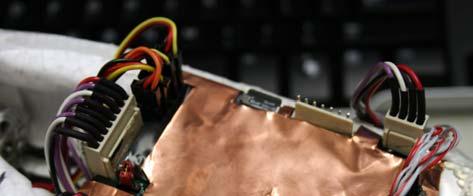
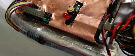
27 CST Microwave Studio Simulation of a RCD Shield with various lifted terminations: 27
28 Shield Materials 28
29 Key Issues Determining Shield Performance: Shield Materials Conductivity ( (The measure of the ability of a material to conduct an electric current.) Permeability ( The measure of the ability of a material to support the formation of a magnetic field within itself.) 29
 Where: R is the electrical resistance of a uniform specimen l is the length A is the")
30 Required Material Size for Equivalent Conductivity These squares are different metals sized for constant conductivity: =l/(ra) Where: R is the electrical resistance of a uniform specimen l is the length A is the area 30
31 Key Issues Determining Shield Performance: Shield Geometry 1. Continuity of the shield and connections. 2. Thickness (important for low frequency magnetic field applications). 3. Apertures (which always impact negatively Shielding Effectiveness). 4. Near Field or Far Field Emissions (where is the source of emissions?). 31
32 Shielding in a Nutshell: How do Shields Work? Reflection at the boundary surfaces (Low Frequencies) Absorption as fields attempt to transverse the shield (High Frequencies) Magnetic Field Shunting (Very Low Frequencies) 32

33 How Do Shields Work? Reflection and Absorption in a Near or Far Field 33
 85 90% of the Emissions Outside of the Shield will be Far Field The External Near Field Exception: Handheld Antenna Testing:")
34 Notes on Near and Far Field Emissions 99% of the Emissions Under the Shield will be Near Field Magnetic (Switched Mode Power Supplies) Electric (DDR RAM, Micro) 85 90% of the Emissions Outside of the Shield will be Far Field The External Near Field Exception: Handheld Antenna Testing: 34
35 Basic Shield Effectiveness Formulas: SE db = 20 log 10 (E t /E i ) (Electric Field) SE db = 20 log 10 (H t /H i ) (Magnetic Field) Where: SE db is the Shielding Effectiveness E i is the Incident Electric Wave E t is the Transmitted Electric Wave H i is the Incident Magnetic Wave H t is the Transmitted Magnetic Wave 35
36 S. A. Schelkunoff Shield Effectiveness Equation: SE db = R db + A db + M db Where: R db is Reflected losses at the outer and inner shield surfaces A db is the Absorption loss through the material M db is the additional losses of Multiple reflections and transmissions within the shield* *M db can be disregarded for shield thicknesses that are much greater than a skin depth. 36
37 Shielding Effectiveness Equations Change if the emissions are Far Field or Near Field The boundary between the Far and Near Field is approximately o /2. Far and Near Field sources have differing source characteristics and E/H ratios. 37
38 Reflection Loss (R db ): Occurs at a Boundary Where the is a difference in the Conductivity ( and Permeability (µ) of Two Materials (Air and Shield) The Greater the Difference, the Greater the Reflection Loss Low Frequency Dominant (Switch Mode Power Supplies) 38
39 Reflection Loss (R db ) General Formula for Far Fields: R db = log 10 ( r / r f) Where: r = Conductivity relative to Copper r = Relative permeability relative to free space f = Frequency Note, Reflection loss is greatest for: Low Frequency (f) High Conductivity ( r ) Low Permeability ( r ) The larger the R db the better the Shield. 39

40 Far Field Reflection Loss (R db ) Example: Material r r R R Copper db 98 db Nickel Silver db 86 db Steel db 58 db R db = log 10 ( r / r f) 40
41 Absorption Loss (A db ): Absorption Loss is the exponential decay of energy due to ohmic and heating of the material which occurs when an electromagnetic wave passes through a medium. High Frequency Dominant (Video Data, DDR, Micro Data Communications) 41
 which is: = (2/ ) 0.5 (meters) Or: = 2.6/(f r r ) 0.")
42 A little aside, Skin Depth ( ) To understand Absorption Losses, there is a need to understand the term Skin Depth. What is Skin Depth? The distance required for the wave to be attenuated to 1/e or 37% of its original value is defined as the Skin Depth ( ) which is: = (2/ ) 0.5 (meters) Or: = 2.6/(f r r ) 0.5 (inches) Remember this term: (Skin Depth) it is important. 42
43 Back to Absorption Loss (A db ): Where: t = thickness Skin Depth A = e t/ Or in db: A db = 20 log 10 e t/ Note, Absorption Loss is greatest for: Greater Thickness (t) Smaller Skin Depth ( Higher Frequency, Greater Conductivity (, Greater Permeability (µ) The Larger the A db the better the Shield 43

44 Far Field Absorption Loss (A db ) for a 20 mil sheet of Copper, Nickel Silver, and Steel A db = 20 log 10 e t/ 44

45 Far Field Summation of Reflection Loss (R db ) and Absorption Loss (A db ) of a 20 mil Copper,20 mil Nickel Silver, and 20 mil Steel Shield Schelkunoff Shield Effectiveness Equation: SE db = R db + A db 45

46 Far Field Shield Absorption Loss (A db ) with Changing Shield Thicknesses for Copper, Steel, and Nickel Silver: 46
47 Near Field Reflection Losses For Both Magnetic and Electric Fields Magnetic Field Source: R m,db = log 10 (fr 2 r / r ) Electric Field Source: R e,db = log 10 ( r / r f 3 r 2 ) Where r = distance from source 47


48 Near Field Reflection Losses for Steel, Copper, and Nickel Silver: Reflection Losses of Magnetic Field Reflection Losses of Electric Field 48
49 Near Field Absorption Losses: A = e t/ where t = thickness Or A db = 20 log 10 e t/ This is the same equation as the far field. 49

50 Comparison of Near Field Reflection Loss (Electric and Magnetic) and Absorption Loss in a 20 mil Steel, Nickel Silver, and Copper Shield: A db = 20 log 10 e t/ R m,db = log 10 (fr 2 r / r ) R e,db = log 10 ( r / r f 3 r 2 ) = (2/ ) 1/2 (meters) 50
51 Summary of Fields and Losses: I. For far field sources: II. III. A. Reflection loss is predominant at the lower frequencies B. Absorption loss is predominant at the higher frequencies. For near field, electric sources: A. Reflection loss is predominant at the lower frequencies B. Absorption loss is predominant at the higher frequencies. For near field, magnetic sources: A. Absorption loss is the dominant shielding mechanism for all frequencies. B. However, both reflection and absorption losses are quite small for near field, magnetic sources at low frequencies. 51
52 Low Frequency Magnetic Shielding in the Near Field: Basic methods for shielding against lowfrequency sources: 1. Diversion of the magnetic flux with high materials 2. Generation of opposing flux via Faraday s law commonly known as the shorted turn method. 52
53 Magnetic Shunting diverting the magnetic flux: 1. Requires a high material to divert magnetic flux. 2. Problems with high materials (Mumetal): 1. High materials are expensive 2. Permeability ( ) is: Nonlinear Decreases with increasing frequency Decreases with increasing magnetic field strength Changes with Mechanical Handling/Treatment Dominant at Very Low Frequencies (High materials are only effective for magnetic fields below 1 khz. This is why shielding enclosures for switching power supplies are constructed from steel rather than Mumetal. Professor Clayton Paul, Introduction to Electromagnetic Compatibility, Second Edition, Page 743.) 53
54 Magnetic Shunting: No effect at High Frequencies: The is approaching in this high material. 54

55 Faraday s Law or Shorted Turn: A changing current in one wire causes a changing magnetic field that induces a current in the opposite direction in an adjacent wire. 55
56 Magnetic Shielding: What is a Magnetic Shield? A shield of high permeability that can shunt, divert, attract, Channel, or guide (like a duct) a magnetic field. Because: High permeability magnetic materials have low reluctance. Therefore: A magnetic field follows the path of least reluctance similar to how current follows the path of least resistance. 56


57 Degree of magnetic shielding is determined by: Material Thickness Shape Position relative to the applied Magnetic Field 57
58 Shield Effectiveness (SE) of Flat Sheets of Different Materials in a Magnetic Field 15 mil Thick CUSE ALSE FESE NISE SSSE.1 () f f Nickel Cold Rolled Steel (SAE 1045) Stainless Steel (430) Copper Aluminum 58
59 Corrosion 59

60 THEORY OF CORROSION: Galvanic and electrolytic corrosion are two types of corrosion suspected in shielding degradation. In both cases the anode metal gets corroded. 60
61 Galvanic corrosion: Anatural phenomenon produced: 1. When two dissimilar metals are brought in contact with each other 2. In the presence of acidic atmospheric moisture. An electrochemical process where the metal with higher anodic index voltage corrodes and an external electric current is produced by an internal chemical reaction. 61
62 Electrolytic Corrosion An electrochemical process: Where the corrosive internal chemical reaction is induced by an externally applied electric potential Although the metals may be similar as opposed to galvanic corrosion (dissimilar metals) 62

63 Material Electrochemical Potentials 63

64 Galvanic Corrosion Risk 64

65 Summations and Conclusions: 65
66 Summations and Conclusions: Shields 1. Shield the Whole active circuit 2. Use THICK Steel for Magnetic Shielding Switch Mode Power Supplies 3. Know what type of field (Near/Far) is the threat (If you want to keep the field on the board then the field is near. If you want to keep the field off of the board then the field is usually far.) 66
67 Summations and Conclusions: Shields 1. Reflection loss is large for electric fields. 2. Reflection loss in normally small for low frequency magnetic fields. 3. Magnetic fields are harder to shield against than electric fields. 4. Use a good conductor to shield against electric fields and high frequency magnetic fields. 5. Use a magnetic material to shield against low frequency magnetic fields. 67
68 Summations and Conclusions: Apertures Keep Apertures dimensions minimal Keep number of Apertures few 68
69 Demonstrations: Measuring Shielding effectiveness of various materials in a Near Field Magnetic Field Aperture Measurement Program Palantir Shield Simulations 69

70 Plane Wave Setup overview 70

71 Overview of Plane Wave Cross Section of Camera 71
72 Field Comparison inside of Camera H field probe 72
73 That s all Question and Answer Time Thank you for attending. 73
74 Questions? 74
75 References 75
76 References: Henry W. Ott, Electromagnetic Compatibility Engineering, Wiley, 2009 Clayton, R. Paul, Introduction to Electromagnetic Compatibility, Wiley Interscience, 2 nd. Ed, 2006 Ralph Morrison, Grounding and Shielding Circuits and Interference, Wiley Interscience, 5 th. Ed, 2007 Tom van Doren, Grounding and Shielding Electronic Systems, T. Van Doren, 1997 Gary Fenical, The Basic Principles of Shielding, In Compliance Magazine, June 2010 Scott Piper (Gentex Corp.) CST Microwave Studio Simulations 76
Some Remarks on Shielding. Herbert Kapitza (FLA) (using slides from a talk by Mike Thuot) DESY,
 (using slides from a talk by Mike Thuot) DESY,") Some Remarks on Shielding Herbert Kapitza (FLA) (using slides from a talk by Mike Thuot) DESY, 09.10.2006 A shield may be used to confine the radiated field from a noise source. Shields are metallic partitions
Some Remarks on Shielding Herbert Kapitza (FLA) (using slides from a talk by Mike Thuot) DESY, 09.10.2006 A shield may be used to confine the radiated field from a noise source. Shields are metallic partitions
Chapter 6 Shielding. Electromagnetic Compatibility Engineering. by Henry W. Ott
 Chapter 6 Shielding Electromagnetic Compatibility Engineering by Henry W. Ott 1 Forward A shield is a metallic partition placed between two regions of space. To maintain the integrity of the shielded enclosure,
Introduction. Concept of shielding
 Shielding Introduction Concept of shielding Shielding of a metal shield (theory) For E field SE.. 2log E E i t For H field SE.. 2log H H i t Do they be equal? Shielding of a metal shield (theory) It depends.
Understanding EMC Basics
 1of 7 series Webinar #1 of 3, February 27, 2013 EM field theory, and 3 types of EM analysis Webinar Sponsored by: EurIng CEng, FIET, Senior MIEEE, ACGI AR provides EMC solutions with our high power RF/Microwave
Todd H. Hubing. Michelin Professor of Vehicle Electronics Clemson University
 Todd H. Hubing Michelin Professor of Vehicle Electronics Clemson University August 4, 2014 IEEE EMC Symposium Fundamentals Workshop 2 August 4, 2014 IEEE EMC Symposium Fundamentals Workshop 3 August 4,
Simulation of Shielding Effectiveness of Materials using CST Studio
 Simulation of Shielding Effectiveness of aterials using CST Studio STANISLAV KOVÁŘ, JAN VALOUCH, HANA URBANČOKOVÁ, ILAN ADÁEK and VÁCLAV ACH Faculty of Applied Informatics Tomas Bata University in lín
SKIN EFFECT : ELECTROMAGNETIC WAVE OR DIFFUSION?
 SKIN EFFECT : ELECTROMAGNETIC WAVE OR DIFFUSION? At high frequencies current in a conductor flows mainly on its surface, and this is known as the skin effect. Two possible mechanisms are given in the published
ELECTROMAGNETIC INTERFERENCE (EMI) ANALYSIS FOR OBLIQUE INCIDENCE OF EM WAVES IN DOUBLE SHIELDS
 ANALYSIS FOR OBLIQUE INCIDENCE OF EM WAVES IN DOUBLE SHIELDS") International Journal of Electronics and Communication Engineering & Technology (IJECET) Volume 6, Issue 11, Nov 2015, pp. 01-09, Article ID: IJECET_06_11_001 Available online at http://www.iaeme.com/ijecetissues.asp?jtype=ijecet&vtype=6&itype=11
International Journal of Electronics and Communication Engineering & Technology (IJECET) Volume 6, Issue 11, Nov 2015, pp. 01-09, Article ID: IJECET_06_11_001 Available online at http://www.iaeme.com/ijecetissues.asp?jtype=ijecet&vtype=6&itype=11
EDDY CURRENT TESTING
 EDDY CURRENT TESTING Introduction Eddy current inspection is a method that use the principal of electromagnetism as the basis for conducting examinations. Eddy Current NDT is a technique that can test
Electromagnetic Waves
 Electromagnetic Waves Maxwell s equations predict the propagation of electromagnetic energy away from time-varying sources (current and charge) in the form of waves. Consider a linear, homogeneous, isotropic
Electrochemistry. Michael Faraday s law of electromagnetic induction says that whenever a conductor is
 Surname 1 Name Course Instructor Date Electrochemistry 1. Faraday s Law Michael Faraday s law of electromagnetic induction says that whenever a conductor is positioned in a changeable magnetic field emf
Lecture 24. April 5 th, Magnetic Circuits & Inductance
 Lecture 24 April 5 th, 2005 Magnetic Circuits & Inductance Reading: Boylestad s Circuit Analysis, 3 rd Canadian Edition Chapter 11.1-11.5, Pages 331-338 Chapter 12.1-12.4, Pages 341-349 Chapter 12.7-12.9,
COLLEGE PHYSICS Chapter 23 ELECTROMAGNETIC INDUCTION, AC CIRCUITS, AND ELECTRICAL TECHNOLOGIES
 COLLEGE PHYSICS Chapter 23 ELECTROMAGNETIC INDUCTION, AC CIRCUITS, AND ELECTRICAL TECHNOLOGIES Induced emf: Faraday s Law and Lenz s Law We observe that, when a magnet is moved near a conducting loop,
BEng. (Hons) Electronics Engineering. Examinations for / Semester 2
 Electronics Engineering. Examinations for / Semester 2") BEng. (Hons) Electronics Engineering Cohort: BTEL/11/FT Examinations for 2013-2014/ Semester 2 MODULE: ELECTROMAGNETIC COMPATIBILITY MODULE CODE: TELC3110 Duration: 2 ½ Hours Instructions to Candidates:
BEng. (Hons) Electronics Engineering Cohort: BTEL/11/FT Examinations for 2013-2014/ Semester 2 MODULE: ELECTROMAGNETIC COMPATIBILITY MODULE CODE: TELC3110 Duration: 2 ½ Hours Instructions to Candidates:
INTRODUCTION TO TRANSMISSION LINES DR. FARID FARAHMAND FALL 2012
 INTRODUCTION TO TRANSMISSION LINES DR. FARID FARAHMAND FALL 2012 http://www.empowermentresources.com/stop_cointelpro/electromagnetic_warfare.htm RF Design In RF circuits RF energy has to be transported
Electromagnetic Testing (ET)
") Electromagnetic Testing Electromagnetic testing is a general test category that includes Eddy Current testing (ECT), Alternating Current Field Measurement (ACFM) and Remote Field testing. All of these
Electromagnetic Testing Electromagnetic testing is a general test category that includes Eddy Current testing (ECT), Alternating Current Field Measurement (ACFM) and Remote Field testing. All of these
Ring Cores General Information
 Ring s General Information Our product line includes a wide range of ring cores with finely graded diameters ranging from 2,5 to 200 mm (see overview of available types). Other core heights can be supplied
Shielding 101. Good Design? Bad Design?
 Shielding 101 Good Design? Bad Design? What Shall We Talk About? Review basics of the plane electromagnetic shield as developed by Schelkunoff Highlights of magnetic field shielding to consider Additional
Study of Specific Absorption Rate (SAR) in the human head by metamaterial attachment
 in the human head by metamaterial attachment") Study of Specific Absorption Rate (SAR) in the human head by metamaterial attachment M. T Islam 1a), M. R. I. Faruque 2b), and N. Misran 1,2c) 1 Institute of Space Science (ANGKASA), Universiti Kebangsaan
Study of Specific Absorption Rate (SAR) in the human head by metamaterial attachment M. T Islam 1a), M. R. I. Faruque 2b), and N. Misran 1,2c) 1 Institute of Space Science (ANGKASA), Universiti Kebangsaan
MAGNETIC FIELDS & UNIFORM PLANE WAVES
 MAGNETIC FIELDS & UNIFORM PLANE WAVES Name Section Multiple Choice 1. (8 Pts) 2. (8 Pts) 3. (8 Pts) 4. (8 Pts) 5. (8 Pts) Notes: 1. In the multiple choice questions, each question may have more than one
CHAPTER 9 ELECTROMAGNETIC WAVES
 CHAPTER 9 ELECTROMAGNETIC WAVES Outlines 1. Waves in one dimension 2. Electromagnetic Waves in Vacuum 3. Electromagnetic waves in Matter 4. Absorption and Dispersion 5. Guided Waves 2 Skip 9.1.1 and 9.1.2
NEW SOUTH WALES DEPARTMENT OF EDUCATION AND TRAINING Manufacturing and Engineering ESD. Sample Examination EA605
 Name: NEW SOUTH WALES DEPARTMENT OF EDUCATION AND TRAINING Manufacturing and Engineering ESD Sample Examination EA605 EDDY CURRENT TESTING AS3998 LEVEL 2 GENERAL EXAMINATION 6161C * * * * * * * Time allowed
Objective Type Questions Instrumentation System & Devices (IDS)
") 1. A balance beam scale uses which of the following units? a. grams b.pounds c. ounces d. kilograms 2. Which of the following would be about the height of the average doorway? a. 2 meters b. 2 centimeters
1. A balance beam scale uses which of the following units? a. grams b.pounds c. ounces d. kilograms 2. Which of the following would be about the height of the average doorway? a. 2 meters b. 2 centimeters
1 P a g e h t t p s : / / w w w. c i e n o t e s. c o m / Physics (A-level)
") 1 P a g e h t t p s : / / w w w. c i e n o t e s. c o m / Physics (A-level) Electromagnetic induction (Chapter 23): For a straight wire, the induced current or e.m.f. depends on: The magnitude of the magnetic
1 P a g e h t t p s : / / w w w. c i e n o t e s. c o m / Physics (A-level) Electromagnetic induction (Chapter 23): For a straight wire, the induced current or e.m.f. depends on: The magnitude of the magnetic
Levitation by Using Electromagnetic Force
 Levitation by Using Electromagnetic Force Mireia Colom Guerra (University of Barcelona), Marc Serra Peralta (Autonomous University of Barcelona), Dalibor Danilovic (Ivanjica Gymnasium). ABSTRACT: In the
Lightning Phenomenology Notes Note 23 8 Jan Lightning Responses on a Finite Cylindrical Enclosure
 Lightning Phenomenology Notes Note 23 8 Jan 2014 Lightning Responses on a Finite Cylindrical Enclosure Kenneth C. Chen and Larry K. Warne Sandia National Laboratories, P. O. Box 5800, Albuquerque, NM 87185,
<CMC Beads as a New EM Absorber >
 Page 1 of 2 - Mechanism of Electromagnetic Wave Absorption - < Conventional Electromagnetic Wave Absorber> In general, the materials used for absorbing the electromagnetic(em) waves are classified; (1)
Question 1. (Marks 16)
") 5 Question 1. (Marks 16) Consider the circuit shown in the figure, where C 1 = 6.00µF, C 2 = 3.00µF, and V = 20.0V. Capacitor C 1 is first charged by closing switch S 1. Switch S 1 is then opened, and
5 Question 1. (Marks 16) Consider the circuit shown in the figure, where C 1 = 6.00µF, C 2 = 3.00µF, and V = 20.0V. Capacitor C 1 is first charged by closing switch S 1. Switch S 1 is then opened, and
Cambridge International Examinations Cambridge International Advanced Subsidiary and Advanced Level
 Cambridge International Examinations Cambridge International Advanced Subsidiary and Advanced Level *3828804905* PHYSICS 9702/42 Paper 4 A Level Structured Questions May/June 2017 2 hours Candidates answer
Electromagnetism Review Sheet
 Electromagnetism Review Sheet Electricity Atomic basics: Particle name Charge location protons electrons neutrons + in the nucleus - outside of the nucleus neutral in the nucleus What would happen if two
TRANSFORMERS B O O K P G
 TRANSFORMERS B O O K P G. 4 4 4-449 REVIEW The RMS equivalent current is defined as the dc that will provide the same power in the resistor as the ac does on average P average = I 2 RMS R = 1 2 I 0 2 R=
Basic physics Questions
 Chapter1 Basic physics Questions S. Ilyas 1. Which of the following statements regarding protons are correct? a. They have a negative charge b. They are equal to the number of electrons in a non-ionized
THE UNITED REPUBLIC OF TANZANIA NATIONAL EXAMINATIONS COUNCIL CERTIFICATE OF SECONDARY EDUCATION EXAMINATION
 THE UNITED REPUBLIC OF TANZANIA NATIONAL EXAMINATIONS COUNCIL CERTIFICATE OF SECONDARY EDUCATION EXAMINATION 031/1 PHYSICS 1 (For Both School and Private Candidates) TIME: 3 Hours Thursday 16 th October
ELECTROCHEMICAL CELLS
 Experiment 11 ELECTROCHEMICAL CELLS Prepared by Ross S. Nord, Masanobu M. Yamauchi, and Stephen E. Schullery, Eastern Michigan University PURPOSE You will construct a table of reduction potentials and
Book Page cgrahamphysics.com Transformers
 Book Page 444-449 Transformers Review The RMS equivalent current is defined as the dc that will provide the same power in the resistor as the ac does on average P average = I 2 RMS R = 1 2 I 0 2 R= V RMS
MAGNETIC FIELDS AND UNIFORM PLANE WAVES
 MAGNETIC FIELDS AND UNIFORM PLANE WAVES Name Section 1. (8 Pts) 2. (8 Pts) 3. (8 Pts) 4. (6 Pts) 5. (6 Pts) 6. (4 Pts) 7. (20 Pts) 8. (20 Pts) 9. (20 Pts) Total Notes: 1. Please read over all questions
PDN Planning and Capacitor Selection, Part 2
 by Barry Olney column BEYOND DESIGN PDN Planning and Capacitor Selection, Part 2 In last month s column, PDN Planning and Capacitor Selection Part 1, we looked closely at how to choose the right capacitor
Computation of Electromagnetic Energy Absorption in the Human Body Tissues by High Frequency Structure Simulator
 Computation of Electromagnetic Energy Absorption in the Human... Computation of Electromagnetic Energy Absorption in the Human Body Tissues by High requency Structure Simulator Md. Selim Hossain 1 and
Outline of College Physics OpenStax Book
 Outline of College Physics OpenStax Book Taken from the online version of the book Dec. 27, 2017 18. Electric Charge and Electric Field 18.1. Static Electricity and Charge: Conservation of Charge Define
Capacitors. Charging a Capacitor. Charge and Capacitance. L05: Capacitors and Inductors
 L05: Capacitors and Inductors 50 Capacitors 51 Outline of the lecture: Capacitors and capacitance. Energy storage. Capacitance formula. Types of capacitors. Inductors and inductance. Inductance formula.
7/06 Electric Fields and Energy
 Part ASome standard electric field and potential configurations About this lab: Electric fields are created by electric charges and exert force on charges. Electric potential gives an alternative description.
Calculus Relationships in AP Physics C: Electricity and Magnetism
 C: Electricity This chapter focuses on some of the quantitative skills that are important in your C: Mechanics course. These are not all of the skills that you will learn, practice, and apply during the
Sandia National Laboratories, P. O. Box 5800, Albuquerque, NM 87185, USA
 Progress In Electromagnetics Research M, Vol. 23, 299 3, 22 LINEAR DIFFUSION INTO A FARADAY CAGE K. C. Chen *, Y. T. Lin, L. K. Warne, and K. O. Merewether Sandia National Laboratories, P. O. Box 58, Albuquerque,
ε induced Review: Self-inductance 20.7 RL Circuits Review: Self-inductance B induced Announcements
 Announcements WebAssign HW Set 7 due this Friday Problems cover material from Chapters 20 and 21 We re skipping Sections 21.1-21.7 (alternating current circuits) Review: Self-inductance induced ε induced
PERFORMANCE SPECIFICATION SHEET
 INCH-POUND MIL-PRF-22885/77F 2 August 2018 SUPERSEDING MIL-PRF-22885/77E 25 April 2013 PERFORMANCE SPECIFICATION SHEET SWITCHES, PUSH BUTTON, ILLUMINATED, 4-LAMP, 0.75 SQUARE, 7.5 AMPERES, AND LOW LEVEL
Ground Penetrating Radar & By Mike Kelty Western Technologies Inc.
 Ground Penetrating Radar & Thermorgraphy By Mike Kelty Western Technologies Inc. Overview Types of Locating Methods/Equipment How GPR Works GPR Applications How Thermography Works Thermography Applications
IE1206 Embedded Electronics
 IE1206 Embedded Electronics Le1 Le3 Le4 Le2 Ex1 Ex2 PIC-block Documentation, Seriecom Pulse sensors I, U, R, P, series and parallel KC1 LAB1 Pulse sensors, Menu program Start of programing task Kirchhoffs
Definition Application of electrical machines Electromagnetism: review Analogies between electric and magnetic circuits Faraday s Law Electromagnetic
 Definition Application of electrical machines Electromagnetism: review Analogies between electric and magnetic circuits Faraday s Law Electromagnetic Force Motor action Generator action Types and parts
Magnetic Fields
 Magnetic circuits introduction Becomes aware of the similarities between the analysis of magnetic circuits and electric circuits. Develop a clear understanding of the important parameters of a magnetic
R. W. Erickson. Department of Electrical, Computer, and Energy Engineering University of Colorado, Boulder
 R. W. Erickson Department of Electrical, Computer, and Energy Engineering University of Colorado, Boulder Part III. Magnetics 13 Basic Magnetics Theory 14 Inductor Design 15 Transformer Design 1 Chapter
EDEXCEL NATIONAL CERTIFICATE/DIPLOMA UNIT 5 - ELECTRICAL AND ELECTRONIC PRINCIPLES NQF LEVEL 3. OUTCOME 3 - MAGNETISM and INDUCTION
 EDEXCEL NATIONAL CERTIFICATE/DIPLOMA UNIT 5 - ELECTRICAL AND ELECTRONIC PRINCIPLES NQF LEVEL 3 OUTCOME 3 - MAGNETISM and INDUCTION 3 Understand the principles and properties of magnetism Magnetic field:
Sound radiation and transmission. Professor Phil Joseph. Departamento de Engenharia Mecânica
 Sound radiation and transmission Professor Phil Joseph Departamento de Engenharia Mecânica SOUND RADIATION BY A PISTON The piston generates plane waves in the tube with particle velocity equal to its own.
PRE-BOARD EXAMINATION STD : XII MARKS : 150
 PRE-BOARD EXAMINATION STD : XII MARKS : 150 SUB : PHYSICS TIME : 3.00 Hrs I.Choose the correct answer: 30x1=30 1.Which of the following quantities not a scalar? a)electric flux b) electric potential c)
EFFECTIVE SKIN DEPTH FOR MULTILAYER COATED CONDUCTOR
 Progress In Electromagnetics Research M, Vol. 9, 1 8, 2009 EFFECTIVE SKIN DEPTH FOR MULTILAYER COATED CONDUCTOR H.-W. Deng and Y.-J. Zhao College of Information Science and Technology Nanjing University
Fig. 1. Two common types of van der Pauw samples: clover leaf and square. Each sample has four symmetrical electrical contacts.
 15 2. Basic Electrical Parameters of Semiconductors: Sheet Resistivity, Resistivity and Conduction Type 2.1 Objectives 1. Familiarizing with experimental techniques used for the measurements of electrical
ELECTROCHEMICAL CELLS
 Experiment 11 ELECTROCHEMICAL CELLS Prepared by Ross S. Nord, Masanobu M. Yamauchi, and Stephen E. Schullery, Eastern Michigan University PURPOSE You will construct a table of reduction potentials and
Two point charges, A and B, lie along a line separated by a distance L. The point x is the midpoint of their separation.
 Use the following to answer question 1. Two point charges, A and B, lie along a line separated by a distance L. The point x is the midpoint of their separation. 1. Which combination of charges would yield
BLUE PRINT FOR MODEL QUESTION PAPER 4
 Unit Chapter Teaching Hours Marks allotted (VSA) mark (SA) 3 mark (SA) 5 mark (LA) 5 mark (NP) BLUE PRINT FOR MODEL QUESTION PAPER 4 SUBJECT : PHYSICS (33) CLASS : II PUC Topic Electric Charges and Fields
The objective of a grounding system are: 1. To provide safety to personnel during normal and fault conditions by limiting step and touch potential.
 GROUNDING SYSTEMS Part 1 Professor Ahdab Elmorshedy 1 Reference: High Voltage Engineering Theory and Practice, Text Book, Marcel Dekker Inc. NY, USA, 2000. Mazen Abdel-Salam, Hussein Anis, Ahdab Elmorshedy,
Electromagnetic Induction (Chapters 31-32)
") Electromagnetic Induction (Chapters 31-3) The laws of emf induction: Faraday s and Lenz s laws Inductance Mutual inductance M Self inductance L. Inductors Magnetic field energy Simple inductive circuits
Electromagnetic Induction (Chapters 31-3) The laws of emf induction: Faraday s and Lenz s laws Inductance Mutual inductance M Self inductance L. Inductors Magnetic field energy Simple inductive circuits
Transmission Lines. Plane wave propagating in air Y unguided wave propagation. Transmission lines / waveguides Y. guided wave propagation
 Transmission Lines Transmission lines and waveguides may be defined as devices used to guide energy from one point to another (from a source to a load). Transmission lines can consist of a set of conductors,
5G50.52 Energy Storage with Superconductors
 5G50.52 Energy Storage with Superconductors Abstract Superconductors oppose magnetic fields and are generally considered to have zero resistivity. Theoretically then, a current in a superconducting ring
Module 2 : Transmission Lines. Lecture 1 : Transmission Lines in Practice. Objectives. In this course you will learn the following
 Objectives In this course you will learn the following Point 1 Point 2 Point 3 Point 4 Point 5 Point 6 Point 7 Point 8 Point 9 Point 10 Point 11 Point 12 Various Types Of Transmission Line Explanation:
Energy Losses in the Electrical Circuits
 Energy Losses in the Electrical Circuits Motors, lighting systems, wiring, mechanical terminations, distribution panels, protective devices, transformers, switchgear, and all end of circuit equipment experience
IE1206 Embedded Electronics Le2
 Le1 Le3 Le4 Le6 Le8 IE1206 Embedded Electronics Le2 Ex1 Ex2 Ex4 Ex5 PIC-block Documentation, Seriecom Pulse sensors I, U, R, P, serial and parallel KC1 LAB1 Pulse sensors, Menu program Kirchhoffs laws
11 SEPTEMBER This document consists of printed pages.
 S 11 SEPTEMBER 2017 6 Write your name, centre number, index number and class in the spaces at the top of this page and on all work you hand in. Write in dark blue or black pen on both sides of the paper.
An Entropy Approach to Wireless Power Transmission by Magnetic Resonance
 Applied Physics Research; Vol. 5, No. 5; 2013 ISSN 1916-9639 E-ISSN 1916-9647 Published by Canadian Center of Science and Education An Entropy Approach to Wireless Power Transmission by Magnetic Resonance
UNIVERSITY OF CAMBRIDGE INTERNATIONAL EXAMINATIONS General Certificate of Education Advanced Level
 XtremePapers.com UNIVERSITY OF CAMBRIDGE INTERNATIONAL EXAMINATIONS General Certificate of Education Advanced Level *0305126326* PHYSICS 9702/41 Paper 4 A2 Structured Questions October/November 2013 2
Chapter 30. Inductance
 Chapter 30 Inductance Self Inductance When a time dependent current passes through a coil, a changing magnetic flux is produced inside the coil and this in turn induces an emf in that same coil. This induced
Chapter 22. Induction
 Chapter 22 Induction Induced emf A current can be produced by a changing magnetic field First shown in an experiment by Michael Faraday A primary coil is connected to a battery A secondary coil is connected
RADIO AMATEUR EXAM GENERAL CLASS
 RAE-Lessons by 4S7VJ 1 CHAPTER- 2 RADIO AMATEUR EXAM GENERAL CLASS By 4S7VJ 2.1 Sine-wave If a magnet rotates near a coil, an alternating e.m.f. (a.c.) generates in the coil. This e.m.f. gradually increase
ELECTROMAGNETIC WAVES
 UNIT V ELECTROMAGNETIC WAVES Weightage Marks : 03 Displacement current, electromagnetic waves and their characteristics (qualitative ideas only). Transverse nature of electromagnetic waves. Electromagnetic
ELECTROCHEMICAL CELLS
 Experiment 11 ELECTROCHEMICAL CELLS Prepared by Ross S. Nord, Masanobu M. Yamauchi, and Stephen E. Schullery, Eastern Michigan University PURPOSE You will construct a series of electrochemical cells. For
PRACTICE NO. PD-AP-1309 PREFERRED PAGE 1 OF 5 RELIABILITY PRACTICES ANALYSIS OF RADIATED EMI FROM ESD EVENTS CAUSED BY SPACE CHARGING
 PREFERRED PAGE 1 OF 5 RELIABILITY PRACTICES ANALYSIS OF RADIATED EMI FROM ESD EVENTS Practice: Modeling is utilized for the analysis of conducted and radiated electromagnetic interference (EMI) caused
UNIVERSITY OF CAMBRIDGE INTERNATIONAL EXAMINATIONS General Certificate of Education Advanced Level
 www.xtremepapers.com UNIVERSITY OF CAMBRIDGE INTERNATIONAL EXAMINATIONS General Certificate of Education Advanced Level *9061759643* PHYSICS 9702/41 Paper 4 A2 Structured Questions October/November 2012
Magnetic shielding and the distortion of magnetic fields
 Magnetic shielding and the distortion of magnetic fields Magnetic Shielding When electromagnetic fields affect sensitive equipment, shielding is needed in order to lessen or negate the effect. Magnetic
Prentice Hall: Conceptual Physics 2002 Correlated to: Tennessee Science Curriculum Standards: Physics (Grades 9-12)
") Tennessee Science Curriculum Standards: Physics (Grades 9-12) 1.0 Mechanics Standard: The student will investigate the laws and properties of mechanics. The student will: 1.1 investigate fundamental physical
Tennessee Science Curriculum Standards: Physics (Grades 9-12) 1.0 Mechanics Standard: The student will investigate the laws and properties of mechanics. The student will: 1.1 investigate fundamental physical
METHODS OF THEORETICAL PHYSICS
 METHODS OF THEORETICAL PHYSICS Philip M. Morse PROFESSOR OF PHYSICS MASSACHUSETTS INSTITUTE OF TECHNOLOGY Herman Feshbach PROFESSOR OF PHYSICS MASSACHUSETTS INSTITUTE OF TECHNOLOGY PART II: CHAPTERS 9
Radioactivity INTRODUCTION. Natural Radiation in the Background. Radioactive Decay
 Radioactivity INTRODUCTION The most common form of radiation is the electromagnetic wave. These waves include low energy radio waves, microwaves, visible light, x-rays, and high-energy gamma rays. Electromagnetic
MAGNETIC PARTICLE INSPECTION (MPI)
") MAGNETIC PARTICLE INSPECTION (MPI) Magnetic particle inspection (MPI) is a method that can be used to detect surface and near surface defects or flaws in ferromagnetic materials such as steel and iron.
MAGNETIC PARTICLE INSPECTION (MPI) Magnetic particle inspection (MPI) is a method that can be used to detect surface and near surface defects or flaws in ferromagnetic materials such as steel and iron.
EXPERIMENT 18 THE PHOTOELECTRIC EFFECT
 220 18-1 I. THEORY EXPERIMENT 18 THE PHOTOELECTRIC EFFECT When light or other electromagnetic waves of sufficiently high frequency fall on a metal surface, they cause electrons to be emitted by the surface.
Cambridge International Examinations Cambridge International Advanced Level
 Cambridge International Examinations Cambridge International Advanced Level *6592581051* PHYSICS 9702/41 Paper 4 A2 Structured Questions May/June 2015 2 hours Candidates answer on the Question Paper. No
Switched Mode Power Conversion
 Inductors Devices for Efficient Power Conversion Switches Inductors Transformers Capacitors Inductors Inductors Store Energy Inductors Store Energy in a Magnetic Field In Power Converters Energy Storage
A Circuit Approach to Teaching Skin Effect
 35 A Circuit Approach to Teaching Skin Effect James H. Spreen Indiana Institute of Technology Abstract: This paper presents a circuits-based approach to describing skin effect. A student project in library
Outside the solenoid, the field lines are spread apart, and at any given distance from the axis, the field is weak.
 Applications of Ampere s Law continued. 2. Field of a solenoid. A solenoid can have many (thousands) of turns, and perhaps many layers of windings. The figure shows a simple solenoid with just a few windings
Chapter 30. Inductance. PowerPoint Lectures for University Physics, 14th Edition Hugh D. Young and Roger A. Freedman Lectures by Jason Harlow
 Chapter 30 Inductance PowerPoint Lectures for University Physics, 14th Edition Hugh D. Young and Roger A. Freedman Lectures by Jason Harlow Learning Goals for Chapter 30 Looking forward at how a time-varying
GCSE PHYSICS REVISION LIST
 GCSE PHYSICS REVISION LIST OCR Gateway Physics (J249) from 2016 Topic P1: Matter P1.1 Describe how and why the atomic model has changed over time Describe the structure of the atom and discuss the charges
PHYSICS. Paper 1 (THEORY) Three hours and a quarter
 Three hours and a quarter") PHYSICS Paper 1 (THEORY) Three hours and a quarter (The first 15 minutes of the examination are for reading the paper only. Candidates must NOT start writing during this time). -------------------------------------------------------------------
PHYSICS Paper 1 (THEORY) Three hours and a quarter (The first 15 minutes of the examination are for reading the paper only. Candidates must NOT start writing during this time). -------------------------------------------------------------------
Magnetic Fields INTRODUCTION. The Hall Effect
 Magnetic Fields INTRODUCTION This experiment concerns magnetic forces and fields. You will examine magnetic field lines and forces qualitatively, and measure field strengths using a Hall probe. A magnaprobe
Pre-Lab Questions. Physics 1BL MAGNETISM Spring 2010
 In this lab, you will focus on the concepts of magnetism and magnetic fields and the interaction between flowing charges (electric current) and magnetic fields. You will find this material in Chapter 19
Maxwell s equations and EM waves. From previous Lecture Time dependent fields and Faraday s Law
 Maxwell s equations and EM waves This Lecture More on Motional EMF and Faraday s law Displacement currents Maxwell s equations EM Waves From previous Lecture Time dependent fields and Faraday s Law 1 Radar
Design and Analysis of Electromagnetic Interference Filters and Shields
 Clemson University TigerPrints All Dissertations Dissertations 5-2014 Design and Analysis of Electromagnetic Interference Filters and Shields Andrew McDowell Clemson University, andjoely@gmail.com Follow
AN OVERVIEW OF CORROSION DAMAGE DETECTION IN STEEL BRIDGE STRANDS USING TDR
 AN OVERVIEW OF CORROSION DAMAGE DETECTION IN STEEL BRIDGE STRANDS USING TDR By Wei Liu 1, Robert Hunsperger, Michael Chajes 3, and Eric Kunz 4 ABSTRACT The corrosion of metallic reinforcement is a major
A) n 1 > n 2 > n 3 B) n 1 > n 3 > n 2 C) n 2 > n 1 > n 3 D) n 2 > n 3 > n 1 E) n 3 > n 1 > n 2
 n 1 > n 2 > n 3 B) n 1 > n 3 > n 2 C) n 2 > n 1 > n 3 D) n 2 > n 3 > n 1 E) n 3 > n 1 > n 2") 55) The diagram shows the path of a light ray in three different materials. The index of refraction for each material is shown in the upper right portion of the material. What is the correct order for
55) The diagram shows the path of a light ray in three different materials. The index of refraction for each material is shown in the upper right portion of the material. What is the correct order for
Class XII Physics (Theory)
") DATE : 0/03/209 SET-3 Code No. //3 Regd. Office : Aakash Tower, 8, Pusa Road, New Delhi-000. Ph.: 0-4762346 Class XII Physics (Theory) Time : 3 Hrs. Max. Marks : 70 (CBSE 209) GENERAL INSTRUCTIONS :. All
DATE : 0/03/209 SET-3 Code No. //3 Regd. Office : Aakash Tower, 8, Pusa Road, New Delhi-000. Ph.: 0-4762346 Class XII Physics (Theory) Time : 3 Hrs. Max. Marks : 70 (CBSE 209) GENERAL INSTRUCTIONS :. All
Electromagnetic Induction
 Electromagnetic Induction Name Section Theory Electromagnetic induction employs the concept magnetic flux. Consider a conducting loop of area A in a magnetic field with magnitude B. The flux Φ is proportional
Electron Current Extraction and Interaction of RF mdbd Arrays
 Electron Current Extraction and Interaction of RF mdbd Arrays Jun-Chieh Wang a), Napoleon Leoni b), Henryk Birecki b), Omer Gila b), and Mark J. Kushner a) a), Ann Arbor, MI 48109 USA mkush@umich.edu,
Chapter 29 Molecular and Solid-State Physics
 Chapter 29 Molecular and Solid-State Physics GOALS When you have mastered the content of this chapter, you will be able to achieve the following goals: Definitions Define each of the following terms, and
UNIVERSITY OF CAMBRIDGE INTERNATIONAL EXAMINATIONS General Certificate of Education Advanced Level
 UNIVERSITY OF CAMBRIDGE INTERNATIONAL EXAMINATIONS General Certificate of Education Advanced Level *2900417311* PHYSICS 9702/42 Paper 4 A2 Structured Questions October/November 2010 1 hour 45 minutes Candidates
Solution of Final Exam Problems 1
 of Final Exam Problems Prob. Two different electrical devices have the same power consumption, but one is meant to be operated on 20 V AC and the other on 220 V AC. (a) What is the ratio of their resistances?