1.1. Basic Mechanisms of Heat Transfer
|
|
|
- Ronald Bell
- 6 years ago
- Views:
Transcription
1 1.1. Basc Mechansms f Heat Transfer The basc mechansms f heat transfer are generally cnsdered t be cnductn, cnvectn, blng, cndensatn, and radatn. Of these, radatn s usually sgnfcant nly at temperatures hgher than thse rdnarly encuntered n tubular prcess heat transfer equpment; therefre, radatn wll nt be cnsdered n any great detal n ths Manual. ll f the thers play a vtal rle n equpment desgn and wll frequently appear n the dscussn. In ths sectn, the emphass wll be upn a qualtatve descrptn f the prcesses and a few very basc equatns Cnductn Mechansm Cnductn n a metallc sld s largely due t the randm mvement f electrns thrugh the metal. The electrns n the ht part f the sld have a hgher knetc energy than thse n the cld part and gve up sme f ths knetc energy t the cld atms, thus resultng n a transfer f heat frm the ht surface t the cld. Snce the free electrns are als respnsble fr the cnductn f an electrcal current thrugh a metal, there s a qualtatve smlarty between the ablty f a metal t cnduct heat and t cnduct electrcty. In addtn, sme heat s transferred by nteratmc vbratns. Furer Equatn The detals f cnductn are qute cmplcated but fr engneerng purpses may be handled by a smple equatn, usually called Furer's equatn. Fr the steady flw f heat acrss a plane wall (Fg. 1.1) wth the surfaces at temperatures f T 1, and T 2 where T 1 s greater than T 2 the heat flw Q per unt area f surface (the heat flux) s: Q T = q = k X 1 1 T2 X 2 ΔT = k ΔX (1.1) The quantty k s called the thermal cnductvty and s an expermentally measured value fr any materal. Eq. (1.1) can be wrtten n a mre general frm f the temperature gradent term s wrtten as a dfferental: Q dt = k (1.2) dx The negatve sgn n the equatn s ntrduced t accunt fr the fact that heat s cnducted frm a hgh temperature t a lw temperature, s that ( dt dx) nherently negatve; therefre the duble negatve ndcates a pstve flw f heat n the drectn f decreasng temperature. Cnductn Thrugh a Tube Wall The man advantage f Eq. (1.2) s that t can be ntegrated fr thse cases n whch the crss-sectnal area fr heat transfer changes alng the cnductn path. sectn f tube wall s shwn n Fg Q s the ttal heat cnducted 6
 whch may be ntegrated t 2 L k( T T ) Q = π (1.4) ln ( r r ) If T < T, Q cmes ut negatve; ths just means that the heat flw s nward, reversed frm the sense n whch we tk t.")
2 thrugh the tube wall per unt tme. t the radal pstn r n the tube wall (r r r), the area fr heat transfer fr a tube f length L s = 2π rl. Puttng these nt Eq. (1.2) gves Q 2πrL = k dt dx (1.3) whch may be ntegrated t 2 L k( T T ) Q = π (1.4) ln ( r r ) If T < T, Q cmes ut negatve; ths just means that the heat flw s nward, reversed frm the sense n whch we tk t. Fr thn-walled tubes, the rat f the uter t the nner radus s clse t unty, and we can use the smpler equatn, 2πr L k( T T ) Q = r r (1.5) wth very small errr. Cnductn Thrugh a Bmetallc Wall Smetmes, fr reasns f crrsn, strength and/r ecnmy, a tube s actually cnstructed ut f tw tghtly fttng cncentrc cylnders f dfferent metals as shwn n Fg Nte that r' s the utsde radus f the nner tube and the nsde radus f the uter tube, and T' s the crrespndng temperature. Frm Eq. 1.4 we may wrte drectly fr the nner tube: and fr the uter tube: 2 L k ( T T ') Q = π (1.6) ln ( r' r ) 2 L k ( T ' T ) Q = π (1.7) ln ( r r' ) Snce the same amunt f heat must flw thrugh bth tubes, the Q's are equal. Then the equatns can be cmbned t elmnate the unknwn temperature T', and Q s gven by: T T Q = (1.8) ln( r' / r ) ln( r / r' ) + 2πL k 2πL k 7
3 Cntact Resstance In the prevus sectn, the assumptn was made that the uter surface f the nner cylnder and the nner surface f the uter cylnder were at the same temperature, mplyng that there was n resstance t heat transfer between the tw. Ths assumptn s essentally crrect f the tw surfaces are metallurgcally bnded t ne anther, as can be acheved when ne materal s fused t the ther r when they are bnded by a detnatn wave. The assumptn can be serusly n errr f the tw surfaces are merely n clse physcal cntact, even at the very hgh pressures that can be exerted by shrnk-fttng. Practcal metal surfaces generally have rughnesses rangng frm 10 t 180 mcrnches, the degree and the frm f the rughness dependng upn the metal and the methd f frmng the surface. When tw such surfaces are placed n cntact, the "hlls" are tuchng whle the "valleys" are flled wth the ambent atmsphere, usually ar. Because f the lw thermal cnductvty f gases, practcally all f the heat s cnducted thrugh the pnts n metal-t-metal cntact. t lw pressures, ths wll be nly a small prtn f the surface perhaps less than ne percent and the resultng cnstrctn f the heat flw lnes can lead t an nterface resstance several tmes greater than n the metal slabs themselves. t hgher cntact pressures between the surfaces, the hlls are flattened t gve a greater surface area n cntact n rder t sustan the lad, and the nterface resstance decreases. Varus methds are used t ensure gd thermal cntact ncludng c-extrusns and shrnk-fttng, but repeated thermal cyclng n the nrmal peratn f prcess equpment, tgether wth creep, can cause lng-term serus lss f effcency. Unfrtunately t s almst mpssble t predct cntact resstance n prcess equpment applcatns. Here, as n all prcess equpment desgn, the engneer must assess the cnsequences f beng wrng and the pssble alternatves Sngle Phase Cnvectn Flud Mtn Near a Surface Cnvectve heat transfer s clsely cnnected t the mechansm f flud flw near a surface, s the frst matter f mprtance s t descrbe ths flw. Sngle phase flw must be characterzed by bth the gemetry f the duct thrugh whch the flw ccurs and by the flw regme f the flud as t ges thrugh the duct. There are tw bascally dfferent types f duct gemetry: cnstant crss-sectn, n whch the area avalable fr flw t the flud has bth the same shape and the same area at each pnt alng the duct, and varyng crss-sectn, n whch the shape and/r the area f the duct vary wth length, usually n a regular and repeated way. The mst cmmn cnstant crss-sectn duct gemetry that ne deals wth n prcess heat transfer applcatns s the cylndrcal tube. In a cylndrcal gemetry, t s assumed that all parameters f the flw are a functn nly f the radal dstance frm the axs f the cylnder (r equvalently frm the wall) and f the dstance frm the entrance (entrance effects). Fr flw n ducts f varyng crss sectn (flw acrss tube banks s the case f nterest here), anther phenmenn ccurs that s f the utmst mprtance n calculatng the pressure drp and whch adversely affects the effcency f cnversn f pressure drp t heat transfer. Whereas n a duct f cnstant crss sectn nly the pressure effect due t the frctn f the flud mvng relatve t the surface (skn frctn) needs t be taken nt accunt, n a bank f tubes frm drag s a majr cntrbutr t the pressure drp. Frm drag arses when the pressure n the frnt surface f a tube s greater than the pressure n the back surface. Ths pressure dfference appears as part f the ttal pressure drp acrss the tube bank; unlke skn frctn, frm drag s nt very effcent n prmtng heat transfer. Frm drag als gves rse t bundary layer separatn and wake frmatn, whch may cause destructve vbratn f the tubes n a tube bank. 8
4 The type f flw n a duct can als be characterzed by the flw regme; that s, lamnar flw, turbulent flw, r sme transtn state havng characterstcs f bth f the lmtng regmes. ll f the exact defntns f lamnar flw are very cmplex, and an llustratn (lke Fg. 1.4) s much mre useful. If we have a rund tube wth a lqud flwng n t at a steady rate, and f we nject a dye trace wth a needle parallel t the axs f the tube, ne f tw thngs can happen: 1) The dye trace may flw smthly dwn the tube as a well-defned lne, nly very slwly becmng thcker, r 2) The dye trace may flw rregularly dwn the tube mvng back and frth acrss the dameter f the tube and eventually becmng cmpletely dspersed. The frst case s lamnar flw and the secnd s turbulent flw. Lamnar flw crrespnds t the smth mvement f layers f flud past ne anther wthut mxng; turbulent flw s characterzed by a rapd exchange f packets r elements f flud n a radal drectn frm ne part f the flw feld t anther thrugh turbulent eddes. There are dfferences n the velcty pattern als. In lamnar flw, the velcty at a gven pnt s steady, whereas n turbulent flw the velcty fluctuates rapdly abut an average value. If ne measures the lcal velcty at varus pstns acrss the tube, ne fnds that lamnar flw gves a parablc velcty dstrbutn whereas turbulent flw gves a blunter velcty prfle, as shwn n Fg In bth flws, the flud velcty s zer at the wall and a maxmum at the centerlne. The flw regme that exsts n a gven case s rdnarly characterzed by the Reynlds number. The Reynlds number has dfferent defntns fr flw n dfferent gemetres, but t s defned as n Eq. 1.9 fr flw nsde tubes: d ρv = μ d G = μ Re (1.9) where d s the nsde dameter f the tube, V s the average velcty n the tube, ρ the densty f the flud, and μ the vscsty f the flud. Lamnar flw s characterzed by lw Reynlds numbers, turbulent flw by hgh Reynlds Numbers. Fr flw nsde tubes, Reynlds numbers belw abut 2,000 result n lamnar flw beng the stable flw regme. Reynlds numbers abve abut 2100 gve turbulent flw fr pressure drp calculatns, whle Reynlds numbers abve 10,000 gve turbulent flw fr heat transfer. The range frm 2100 t 10,000 s generally referred t as the transtn flw regme fr heat transfer. Other gemetres have dfferent Reynlds number ranges t characterze flw regmes. Heat Transfer t a Flwng Flud (Cnvectn) Cnvectn heat transfer can be defned as transprt f heat frm ne pnt t anther n a flwng flud as a result f macrscpc mtns f the flud, the heat beng carred as nternal energy. The cnvectn prcess has receved a great deal f bth expermental and analytcal attentn and, althugh we are manly cncerned wth usng the results f these studes, a cursry lk shuld be taken at the physcal prcess f cnvectn, bth t defne terms and t establsh sme ntutve sense f what really the crrelatns we use are tryng t represent. 9
5 In lamnar flw past a cld wall the heat s transferred t the tube surface frm the flud next t the wall. Wthn the flud, heat s transferred frm "layer" t "layer" f the flud by cnductn. There are n flud mtns perpendcular t the drectn f flw t transprt the heat by any ther mechansm. Snce the dfferent "layers" f flud are mvng at dfferent velctes, hwever, the cnductn prcess s much mre cmplex t analyze than fr the sld wall prevusly dscussed. If we lk at a flud n turbulent flw past a cld surface and mark a few representatve elements f flud n rder t trace ther paths, we wuld btan a pcture smethng lke Fg The crrespndng tme-averaged velcty and temperature prfles mght lk lke Fgs. 1.6 and 1.7. The flw near the wall has nly a few small eddes, s that the predmnant mechansm fr heat transfer s cnductn. t the wall, the flud velcty s zer and the flud temperature s the same as the wall. The velcty and temperature gradents near the wall are much steeper than thse n the bulk flw where eddy transprt becmes dmnant. It s mprtant t nte that when we refer wthut further qualfcatn t the velcty r temperature f a stream, we mean the vlume-mean r mxng-cup values shwn n the fgures as V and T f. (We wll drp the bars hencefrth.) Hwever, t s mprtant t remember that sme prtns f the flud are at pssbly sgnfcantly hgher r lwer temperatures, where thermal degradatn r phase change mght ccur. Fr the case shwn, f the flud had a freezng temperature between T s and T f, a layer f sld wuld frm n the wall, resultng n a majr change n the heat transfer and flud flw mechansms. Flm Heat Transfer Ceffcents Fr many cnvectve heat transfer prcesses, t s fund that the lcal heat flux s apprxmately prprtnal t the temperature dfference between the wall and the bulk f the flud,.e., Q ( T f Ts ) (1.10) whch causes us t defne a cnstant f prprtnalty, called the "flm ceffcent f heat transfer," usually dented by h: Q = h( T f Ts ) (1.11) The value f h depends upn the gemetry f the system, the physcal prpertes and flw velcty f the flud. 10
6 The cncept f a heat transfer ceffcent s useful t the desgner nly f there exsts a quanttatve relatnshp between these varables and the heat transfer ceffcent. It s mprtant als that ths relatnshp be reasnably vald fr the cndtns exstng n the partcular applcatn. These relatnshps, r crrelatns, may cme frm ether theretcal r expermental studes, r frm a cmbnatn f bth. The crrelatn may be expressed as an equatn, a graph, a table f values, r a cmputatnal prcedure. These frms are mre r less readly cnvertble frm ne nt anther accrdng t the needs and cnvenence f the user. In usng the crrelatn, the desgner needs t knw, at least rughly, hw accurate the results are lkely t be n hs applcatn. We smetmes emply a flm ceffcent n cases where the flux s nt even apprxmately prprtnal t the temperature dfference (e.g., nucleate blng), cntradctry t the mplcatn f Eq. (1.10). Ths practce ffers a useful bass f cmparsn f the relatve resstances f the several heat transfer prcesses n a gven prblem, but has n fundamental sgnfcance Tw Phase (Lqud-Gas/Vapr) Flw Regmes f Tw-Phase Flw In the present cntext, tw-phase flw wll usually refer t the smultaneus flw f a lqud and a gas r vapr thrugh a duct. Such a flw ccurs when a vapr s beng cndensed r a lqud s beng vaprzed; less cmmnly, a tw-phase flw may nvlve a gas-lqud mxture (such as ar and water) flwng tgether and beng heated r cled wthut any apprecable change f phase. The actual tw-phase flw cnfguratn, r regme, exstng n a cndut n a gven case depends upn the relatve and abslute quanttes and the physcal prpertes f the fluds flwng, the gemetrc cnfguratn f the cndut, and the knd f heat transfer prcess nvlved, f any. We wll frst cnsder the flw regmes bserved by lves (1) n hs study f ar-water flws n hrzntal tubes. These regmes are dagrammed n rather dealzed frm n Fg The chef dfference between flw regmes studed n a nn-heat transfer stuatn and thse exstng durng cndensatn s that a lqud flm exsts n the entre surface f the cndut durng cndensatn. Hwever, we may presume that ths thn flm f dranng cndensatn des nt cause any vtal dfference n the nteractn between the vapr and the man nventry f lqud. Fr blng flws, there are at least tw addtnal flw regmes requred. In ne, bubbles are frmed n the walls whch dsrupt the flw pattern n the mmedate vcnty f the wall. In rder fr ths t ccur, the wall must be abve the blng pnt (thugh ths des nt guarantee that bubbles wll frm); f the bulk flud temperature s saturated, the bubbles wll be carred ff dwnstream very much lke the bubble flw regme shwn n the Fg. 1.8, but f the bulk flw s subcled, the bubbles wll quckly cllapse. In the latter case, there wll be nly a relatvely small effect upn pressure drp. The secnd new flw regme s mst flw n whch the lqud flm n the wall n mst-annular flw has been evaprated and all the remanng lqud s carred as drplets n the vapr stream. We may vew the flw regme as a cnsequence f the nteractn f tw frces, gravty and vapr shear, actng n dfferent drectns. t lw vapr flw rates, gravty dmnates and ne btans stratfed, slug-plug, r bubble flw dependng upn the relatve amunt f lqud present. t hgh vapr velctes, vapr shear dmnates, gvng rse t wavy, annular, r annular-mst flws. It wuld be desrable t have sme way t predct the flw regme a prr, and many attempts have been made t d ths n a general and cnsstent way. N attempt has succeeded, but the wrk f Baker (2) s cnsdered t be generally the best avalable n the pen lterature even thugh t s a dmensnal 11
7 representatn and defes explanatn n fundamental terms. The Baker map s shwn n mdfed frm as Fg. 1.9 and s useful n gvng a general apprecatn f the general knd f flw regme exstng under gven cndtns. Fr tw-phase flw nsde vertcal tubes, the stratfed and wavy flw regmes cannt exst, and the flw regmes generally recgnzed n ths case are bubble, slug, annular, and annular wth mst. The Far map (3) (Fg. 1.10) s generally recgnzed as the best fr ths cnfguratn and s reprduced here n slghtly mdfed frm. It was rgnally develped fr the analyss f thermsphn reblers and bascally refers t a lqud stream enterng at the bttm f the tube and blng as t flws upward. Fr cndensatn nsde a vertcal tube, the vapr generally enters at the tp and the tw-phase mxture resultng frm cndensatn flws dwnward. t hgh cndensng rates, where vapr shear dmnates, mst f the flw s n the annular flw regme. Fg can be used t estmate when ths assumptn breaks dwn. Our knwledge f tw-phase flw patterns acrss tube banks, wth r wthut baffles, s much mre lmted and ndeed hardly extends beynd what ntutn tells us. Frtunately, at least sme crrelatns f pressure drp and related hydrdynamc effects are largely ndependent f a knwledge f flw pattern, and t s pssble t make sme quanttatve calculatns. Heat Transfer t a Tw-Phase Flw The analyss f heat transfer t r frm a tw-phase flw s qute cmplex, nvlvng the prpertes, quanttes, and flud mechancs f bth phases. The desgn crrelatns resultng frm these analyses are als subject t greater errr than thse fr sngle phase heat transfer. 12
8 Fr a gas-lqud flw nvlvng n change f phase as a result f heat transfer, the flw s usually turbulent. The heat s transferred by turbulent eddes wthn each phase and acrss the gas-lqud and flud-sld nterfaces by turbulent bundary layer phenmena smlar t turbulent flw n a ppe. The rate f heat transfer (and the pressure drp) s relatvely hgh because f the strng turbulence created by the gas-phase shear n the lqud. Where phase changes are als nvlved, as n vaprzatn r cndensatn, addtnal heat transfer mechansms cme nt play. These are dscussed n mre detal n subsequent sectns. Phase Relatnshps n Tw-Phase (Lqud Gas/Vapr) Flw Tw phase flws must als be characterzed n terms f the cmpstn and the resultng thermdynamc relatnshps between the tw phases. Fur cases can be dstngushed: a. The lqud and the gas are dfferent pure cmpnents. The classc example s an ar-water mxture, whch s nt a cmmn ndustral prblem, but s very mprtant because a great deal f what s knwn abut tw-phase flw has been determned n ths system. Whle n general ths nfrmatn can be carred ver t cndensatn and sme blng wrk, there are mprtant dfferences that must be recgnzed and allwed fr. Thermdynamcally, the pressure and temperature can be ndependently vared ver wde ranges n ths system. 13
9 b. The lqud and gas (vapr) are the same pure cmpnent. Ths s a cmmn case n cndenser desgn, ccurrng fr example n cndensers n clumns separatng and/r purfyng a prduct. The pressure-temperature relatnshp n ths case s the vapr pressure curve fr the cmpnent. c. The lqud and gas (vapr) are multcmpnents. The thermdynamc relatnshps are mre cmplex, the temperature, fr example, beng varable ver a range f values at a gven pressure, but wth a changng rat f ttal lqud t ttal vapr and wth changng cmpstn f each phase. Predctn f the amunt and cmpstn f each phase s relatvely well understd and easly dne n few cases, as fr mxtures f lght hydrcarbns; ther cases requre labratry thermdynamc data. d. Ths case s dentcal t N r (c), but wth a nn-cndensable gas present. e.g. [ar n steam, r a slvent n an nert strppng gas]. Ths case s thermdynamcally smlar t (c), but the nn-cndensable gas des nt appear n the lqud phase. Other Tw-Phase Systems Other tw-phase systems ccur n ndustral prcessng and are brefly descrbed belw. In general, less s knwn abut these systems than fr lqud-gas/vapr systems, and the crrelatns are crrespndngly fewer and less accurate. 1. Sld-gas systems. The mst mprtant applcatn f sld-gas mxtures s n fludzed beds, n whch the gas s ntrduced at the bttm f the bed and flws upwards. If the gas flw rate s great enugh, the frces n the sld partcles (usually fnely dvded, such as catalyst partcles r sand) cause the bed t expand. Then the partcles n lnger rest drectly n ne anther and crculate freely thrugh the bed; bubbles f gas rse thrugh the bed and break thrugh the upper surface, gvng an appearance smlar t blng f a lqud. Heat transfer surface n the frm f tubes may be put nt the bed, and heat may als be transferred thrugh the walls that cntan the bed. Heat transfer rates n a fludzed bed are generally much hgher than fr a cmparable flw f gas nly. If the gas rate s ncreased further, the sld partcles are carred alng wth the gas. Ths s ften dne delberately t gve a "transfer lne fludzed catalytc reactr." Heat transfer mechansms n ths case are qualtatvely smlar t thse n gas lqud flw n a ppe, except that nw the "eddes" n the sld phase are cmpsed f masses f dscrete partcles all mvng tgether, rather than a macrscpcally cntnuus phase. 2. Sld-lqud systems. Lqud fludzed beds are als knwn; the majr dfference s that sld and lqud denstes are farly smlar, s the sld s mre easly fludzed and transprted wth the lqud. Heat transfer rates are nly margnally greater than fr the cmparable lqud-nly flw. 3. Lqud-lqud systems. Mxtures f tw mmscble lquds are smetmes encuntered n heat exchangers and flw patterns smlar t thse fr gas-lqud flws are bserved. The heat transfer ceffcents fr these systems are generally ntermedate between the values that wuld be bserved fr the sngle lquds flwng alne at, the same average velcty Cndensatn Mdes f Cndensatn Cndensatn s the prcess by whch a vapr s changed t a lqud by remvng the latent heat f cndensatn frm the vapr. There are fur basc mdes r mechansms f cndensatn generally recgnzed: drpwse, flmwse, drect cntact, and hmgeneus. 1. Drpwse cndensatn. In drpwse cndensatn, the drps f lqud frm frm the vapr at partcularlyfavred lcatns, called nucleatn stes, n a sld surface. These stes may be pts r scratches r any surface rregularty and there may be many thusands f them per square nch. These drps grw by cntnued cndensatn frm the vapr and by agglmeratn f adjacent drps when they cme nt cntact. Drpwse cndensatn 14
10 ccurs nly n surfaces whch are nt strngly wetted by the lqud and s the drps d nt spread ut ver the surface. They grw n place untl they becme s large that they run ff the surface by gravty r are blwn ff by the flwng vapr. Whle drpwse cndensatn s allurng because f the hgh ceffcents reprted, t s nt cnsdered at ths tme t be sutable fr delberate emplyment n prcess equpment. Generally, cntamnants must be cntnuusly njected nt the vapr, r specal surface materals (ften f lw thermal cnductvty) emplyed. Even s, the prcess s unstable and unpredctable, and f questnable effcacy under cndtns f hgh vapr velcty and ndustral practce. 2. Flmwse cndensatn. In flmwse cndensatn, the drps ntally frmed quckly calesce t prduce a cntnuus lqud flm n the surface thrugh whch heat must be transferred t cndense mre lqud. The actual heat transfer mechansm that perates n flmwse cndensatn s clsely related t the tw-phase flw mechansms descrbed n the prevus sectn. Flmwse cndensatn s the usual mde that ccurs n practce and that s assumed t exst fr cndenser desgn calculatns. 3. Drect cntact cndensatn. In drect cntact cndensatn, the lqud clant s sprayed drectly nt the vapr, whch cndenses drectly nt the surface f the spray drps. Drect cntact cndensatn s a very effcent prcess, but t results n mxng the cndensate and clant. Therefre t s useful nly n thse cases where the cndensate s easly separated, r where there s n desre t reuse the cndensate, r where the clant and cndensate are the same substance. 4. Hmgeneus cndensatn. In hmgenus cndensatn, the lqud phase frms drectly frm supersaturated vapr, away frm any macrscpc surface. Snce ths requres subclng the vapr n the rder f a hundred degrees belw the saturatn temperature and snce hmgeneus cndensatn s actually bserved at much smaller subclngs, t s generally assumed that n practce there are suffcent numbers f drt r mst partcles present n the vapr t serve as nucleatn stes. Hmgeneus cndensatn s prmarly f cncern n fg frmatn n equpment and s nt a desgn mde. Cndensatn Outsde Tubes. cmmn cndenser desgn has the vapr utsde a bank f tubes, wth cld clant flwng nsde the tubes. The 15
11 vapr cndenses n the utsde f the tubes n the flmwse mde. Then the flm flws under the nfluence f gravty t the bttm f the tube and drps ff n t the next tube lwer n the bank. If the cndensate s very vscus, ths flmwse flw may be n the lamnar flw regme at least fr the frst few tubes (Fg a). Mre cmmnly, the cndensate s relatvely nvscd (lke water) and the flm quckly becmes turbulent (Fg. 1.11b). The tw cases lead t qute dfferent predctns f the rate f heat transfer f the latent heat f cndensatn f the vapr thrugh the lqud flm. If the vapr flw rate s hgh, vapr shear actng n crssflw n the cndensate flm becmes sgnfcant n blwng ff the lqud, carryng t dwnstream as a spray, and causng the flm t becme turbulent even earler than t wuld have under the nfluence f gravty alne (Fg.1. 11c). Cndensatn Insde Tubes. nther cmmn cndenser cnfguratn, especally n ar-cled cndensers, has the vapr cndensng nsde tubes. The tubes are usually hrzntal r nly slghtly slanted dwnwards t facltate dranage, but vertcal and nclned tube arrangements are als used. If the vapr flw rate s very lw, the cndensate frms n the cld wall and drans under the nfluence f gravty nt a pl n the bttm f the tube; ths pl n turn drans by gravty ut the ext end f the tube (Fg. 1.12a). Ths phenmenn ccurs under cndtns, whch favr the stratfed r wavy flw regmes (see Fgs. 1.8 and 1.9). Cndensatn f Mxtures. There are several mprtant dfferences between the cndensatn f an essentally pure cmpnent and the cndensatn f a mxture. basc analyss f the prblem fr a bnary mxture was gven by Clburn and Drew (4) wh presented the dagram n Fg In a mxture, the heaver, less vlatle cmpnents cndense frst, and nly as the temperature f the remanng vapr s lwered d the lghter cmpnents cndense. Thus, there are always sensble heat transfer effects t be cnsdered n bth the lqud and vapr phases. Because f the 16
12 lw heat transfer ceffcent asscated wth clng the vapr, ths prcess becmes a majr resstance t heat transfer n the prcess, ndcated n the fgure by the temperature dfference (T v -T ). The heaver cmpnent s enrched n the vcnty f the nterface cmpared t the bulk (as ndcated by the cncentratn dfference (y -y v )) and cunter-dffuses back nt the bulk vapr. Snce the cmpstns f bth lqud and vapr phases are cntnually changng, there s the prblem f changng physcal prpertes t cnsder n evaluatng the equatns. The prblem becmes even mre cmplex fr multcmpnent mxtures, and apprxmatn methds must be used t desgn cndensers under these cndtns Vaprzatn Mechansms f Pl Blng. There are several mechansms, r prcesses, thrugh whch a lqud at the saturatn temperature may be cnverted t a vapr by the addtn f heat. If the blng r vaprzatn ccurs n a ht surface n a cntaner n whch the lqud s cnfned, the prcess s called "pl blng." There are several qute dfferent mechansms by whch pl blng ccurs dependng upn the temperature dfference between the surface and the lqud, and t a lesser extent, upn the nature f the surface and the lqud. These mechansms are best dscussed n cnnectn wth a curve f heat flux t the lqud. The classc curve f heat flux vs. temperature dfference between surface and lqud saturatn temperature fr saturated pl blng s reprduced n Fg The crdnates are lgarthmc and the values shwn are typcal f a lght hydrcarbn. The varus regmes ndcated n Fg are: (a) The natural cnvectn regme characterzed by a Δ T less than abut 10 F. In ths regn, the lqud n cntact wth the ht surface s superheated and rses by natural cnvectn t the surface between the vapr and lqud where the superheat s released by quescent vaprzatn f lqud. There s n vapr bubble frmatn n the bulk f the lqud and the heat transfer ceffcents are characterstc f thse f natural cnvectn prcesses. (b) The nucleate blng regme, n whch vapr bubbles are frmed at preferred nucleatn stes - typcally small pts r scratches - n the ht surface. The lqud s superheated by drect cntact wth the sld surface. Once a vapr nucleus frms at a nucleatn ste, the bubbles grw very rapdly by desuperheatng the surrundng lqud untl buyant frces pull them free frm the surface and cause them t rse t the vapr-lqud nterface. There are varus crrelatns that have been prpsed n the lterature fr ths regn. Hwever, because nucleate blng phenmena are s strngly affected by the exact nature f the surface and the flud, t s best t use expermental nfrmatn when desgnng n ths regn. (c) The pnt ndcated by (c) s varusly termed the maxmum, peak, crtcal, r burnut heat flux: the hghest attanable heat flux fr any reasnable surface temperature. t ths pnt, the release f vapr s s vgrus that the flw f lqud t the surface s just suffcent t supply the vapr. ny further ncrease n surface temperature results n sme f the vapr generated beng unable t escape and the heat flux falls ff. The peak heat flux 17
13 phenmenn s essentally a vapr hydrdynamc lmt and s nearly ndependent f the exact nature f the surface. Varus fundamentally-derved crrelatns f the peak heat flux exst. (d) Transtn blng s an ntermedate regme characterzed by the ccasnal generatn f a vapr flm at the surface, whch nsulates the surface frm the clng lqud, leadng t lcal ht spts and unstable peratn. The flm s unstable n the transtn blng regme, and after a shrt perd f tme the lqud wll fld back t cl the surface and temprarly g back nt the nucleate blng regme. Heat transfer equpment s rdnarly never ntended t perate n the transtn regme. (e) Flm blng s the blng regme that s stable at large temperature dfferences between the surface and the saturatn temperature. In flm blng, a stable, almst quescent, flm f vapr exsts between the surface and the lqud pl. Heat transfers by cnductn acrss the vapr t the lqud pl resultng n creatn f mre vaprs. The flm eventually becmes unstable and releases large vapr bubbles at relatvely nfrequent ntervals. The bubbles rse thrugh the pl t the nterface. Flm blng s characterzed by large temperature dfferences, generally very lw heat fluxes, and crrespndngly very lw heat transfer ceffcents. The surface may becme ht enugh t thermally degrade the substance beng bled. Fulng prblems are als strngly accentuated n the flm blng regme because any fulng depst that frms n the surface cannt be re-dsslved r washed away by lqud. In general, t s cnsdered undesrable t perate n the flm blng regme. Vaprzatn Durng Flw. The abve blng prcesses take place n a cntaner r pl f lqud and are therefre referred t as pl blng phenmena. Certan classes f vaprzatn equpment, ntably thermsphn and pump-thrugh reblers, perate wth a net lqud velcty past the heat transfer surface. Under these cndtns, the blng prcesses are mdfed by a shear stress peratng n the layer f lqud mmedately adjacent t the ht surface. In general, natural cnvectn blng phenmena wll be vershadwed by frced cnvectn, and the nucleatn prcess wll be suppressed t sme degree, pssbly cmpletely. Wth cmplete suppressn, the superheated lqud s transprted frm the tube wall by turbulent eddes t the vapr-lqud nterface, where vaprzatn takes place t frm the vapr. The heat transfer ceffcent under these cndtns s greater than that whch wuld exst f nucleate blng nly were peratve. Flm blng s als pssble under frced cnvectn vaprzatn f the wall temperature s hgh enugh. Frequently n these cases, ne encunters mst flw, n whch the lqud nventry s carred alng n the vapr as tny drplets, whch are heated and vaprzed by cntact wth the superheated vapr. Ths prcess s characterzed by very lw heat transfer ceffcents and s never delberately desgned fr n vaprzatn equpment. 18
14 Crrelatns exst whch allw the desgner t estmate the effect f flw phenmena n the blng prcess and f these are fund t be sgnfcant, t calculate the heat transfer ceffcent under frced cnvectn cndtns. Vaprzatn f Mxtures. Mxtures present a serus prblem n the desgn f reblers. Fgs and 1.16 llustrate the prblem. When a wde blng range mxture enters a rebler, the frst vapr t be generated s rch n the lw blng cmpnents, leavng behnd a lqud whch s enrched n the hgh blng cmpnents, especally n the mmedate vcnty f the heat transfer surface. The lght cmpnents then must dffuse thrugh ths barrer t the surface t vaprze. greater drvng frce s requred than s ndcated by the mxed mean cmpstn f the remanng lqud (the prblem s entrely analgus t that f a wde cndensng range mxture dscussed n the prevus sectn.) If ne measures the heat flux as a functn f the blng surface temperature and cmpares t t the saturatn temperature fr the bulk mxture, the apparent result s a decrease n heat transfer ceffcent at cmpstns ntermedate t the pure cmpnents, as llustrated n Fg Hwever, t wuld seem that the real effect s a dstrtn f the temperature drvng frce and that the heat transfer ceffcent tself s n fact a mntncally changng functn frm the pure lght cmpnent t the pure heavy cmpnent. Ths hwever des nt alter the basc prblem whch s hw des ne calculate the true blng heat transfer ceffcent - Δ T prduct, whch s the heat flux, and hence gves the amunt f area requred n the cndenser Radatn Surce f Radant Energy. ll matter cnstantly radates energy n the frm f electrmagnetc waves. The amunt f energy emtted depends strngly upn the abslute temperature f the matter and t a lesser extent upn the nature f the surface f the matter. The basc law f radatn was derved by Stefan and Bltzmann and may be wrtten fr ur purpses as: Q = σε (1.12) 4 T abs 8 4 where σ s the Stefan-Bltzmann cnstant (equal t x 10 Btu/hr ft 2 ( R) ) and Tabs s the abslute temperature n R. ε s the emssvty and has a value between 0 and 1. Fr a perfect reflectr ε = 0 and fr a perfect emtter, a s-called "black bdy", ε = 1. Hghly plshed metals have an emssvty f abut 0.02 t 0.05, xdzed alumnum abut 0.15, steel frm 0.6 t 0.9 whether clean r rusted, and mst pants frm 0.8 t 0.98, largely ndependent f clr. Snce all surfaces that radate heat wll als absrb heat, t fllws that all surfaces that can "see" each ther are exchangng heat wth ne anther, the net rate dependng upn the abslute temperatures, the emssvtes, the areas and 19
15 the spatal gemetrc relatnshps f the surfaces. The cmplete frmulatn f the prblem s qute cmplex and wll nt be develped further here. mng the many excellent texts n the subject s "Radatn Heat Transfer" by L. Segel and J. R. Hwell (5). Radatn n Prcess Heat Transfer Prblems t usual atmspherc temperatures, radant heat transfer s relatvely unmprtant cmpared t mst ther heat transfer mechansms, thugh there are a few areas where t makes a sgnfcant cntrbutn, e.g., the lss f heat frm nnnsulated steam lnes. t hgher temperatures, radatn becmes relatvely mre mprtant, and at temperatures abve perhaps F (dependng upn the ther prcesses), t s usually essental t take radatn nt accunt. Hwever, fr nrmal heat exchanger applcatns such elevated temperatures seldm exst. Therefre, the prncples and equatns f radatn heat transfer wll nt be develped further. 20
16 1.2. Basc Heat Exchanger Equatns The Overall Heat Transfer Ceffcent Cnsder the stuatn n Fg. (1.18). Heat s beng transferred frm the flud nsde (at a lcal bulk r average temperature f T ), thrugh a drt r fulng flm, thrugh the tube wall, thrugh anther fulng flm t the utsde flud at a lcal bulk temperature f T. and are respectvely nsde and utsde surface areas fr heat transfer fr a gven length f tube. Fr a plan r bare cylndrcal tube, 2πr L = 2 π r L = r r (1.13) The heat transfer rate between the flud nsde the tube and the surface f the nsde fulng flm s gven by an equatn f the frm Q/ = h(t f - T s ) where the area s and smlarly fr the utsde cnvectve prcess where the area s. The values f h and h have t be calculated frm apprprate crrelatns. On mst real heat exchanger surfaces n actual servce, a flm r depst f sedment, scale, rganc grwth, etc., wll sner r later develp. few fluds such as ar r lquefed natural gas are usually clean enugh that the fulng s absent r small enugh t be neglected. Heat transfer acrss these flms s predmnantly by cnductn, but the desgner seldm knws enugh abut ether the thckness r the thermal cnductvty f the flm t treat the heat transfer resstance as a cnductn prblem. Rather, the desgner estmates frm a table f standard values r frm experence a fulng factr R f. R f s defned n terms f the heat flux Q/ and the temperature dfference acrss the fulng ΔT f by the equatn: ΔT f R f = (1.14) Q / Frm Eq.1.14, t s clear that R f s equvalent t a recprcal heat transfer ceffcent fr the fulng, h f : Q h f = 1 = (1.15) R f ΔT f and n many bks, the fulng s accunted fr by a "fulng heat transfer ceffcent," whch s stll an estmated quantty. The effect f ncludng ths addtnal resstance s t prvde an exchanger smewhat larger than requred when t s clean, s that the exchanger wll stll prvde the desred servce after t has been n stream fr sme tme and sme fulng has accumulated. 21
17 The rate f heat flw per unt length f tube must be the same acrss the nsde flud flm, the nsde drt flm, the wall, the utsde drt flm, and the utsde flud flm. If we requre that the temperature dfferences acrss each f these resstances t heat transfer add up t the verall temperature dfference, (T - T ), we btan fr the case shwn n Fg.1.18 the equatn Q = 1 h R + f T T ( r / r ) ln + 2πLk w R + f 1 + h (1.16) In wrtng Eq. (1.16), the fulng s assumed t have neglgble thckness, s that the values f r, r, and are thse f the clean tube and are ndependent f the buldup f fulng. Nt nly s ths cnvenent we dn't knw enugh abut the fulng t d anythng else. Nw we defne an verall heat transfer ceffcent U * based n any cnvenent reference area * : ( T T Q U ) (1.17) Cmparng the last tw equatns gves: U * = * h R f + * + * ln 1 ( r / r ) 2πLk w R f + * * + h (1.18) Frequently, but nt always, * s chsen t be equal t, n whch case U * = U, and Eq. (1.18) becmes: U = h R f ln 2πLk ( r / r ) w + R f 1 + h (1.19) If the reference area * s chsen t be, the crrespndng verall heat transfer ceffcent U s gven by: U = 1 h + R f + ln ( r / r ) 2πLk w 1 R f + + h (1.20) The equatn as wrtten apples nly at the partcular pnt where (T - T ) s the drvng frce. The questn f applyng the equatn t an exchanger n whch T and T vary frm pnt t pnt s cnsdered n the next sectn. The wall resstance s rdnarly relatvely small, and t a suffcent degree f precsn fr bare tubes, we may usually wrte 22
18 ln ( r / r ) 2πLk w 1 2 r ΔX ( r + r ) k w ( r / r ) ln ; 2πLk w 1 2 r ΔX ( r + r ) k w (1.21) Inspectn f the magntudes f the terms n the denmnatr f Eqs r 1.20 fr any partcular desgn case quckly reveals whch term r terms (and therefre whch heat transfer resstance) predmnates. Ths term (r terms) cntrls the sze f the heat exchanger and s the ne upn whch the desgner shuld cncentrate hs attentn. Perhaps the verall heat transfer ceffcent can be sgnfcantly mprved by a change n the desgn r peratng cndtns f the heat exchanger. In any case, the desgner must gve partcular attentn t calculatng r estmatng the value f the largest resstance, because any errr r uncertanty n the data, the crrelatn, r the calculatn f ths term has a dsprprtnately large effect upn the sze f the exchanger and/r the cnfdence that can be placed n ts ablty t d the jb The Desgn Integral In the prevus sectn, we btaned an equatn that related the rate f heat transfer t the lcal temperature dfference (T-t) and the heat transfer area, thrugh the use f an verall heat transfer ceffcent U. In mst exchanger applcatns, hwever, ne r bth f the stream temperatures change frm pnt t pnt thrugh the flw paths f the respectve streams. The change n temperature f each stream s calculated frm the heat (enthalpy) balance n that stream and s a prblem n thermdynamcs. Our next cncern s t develp a methd applyng the equatns already btaned t the case n whch the temperature dfference between the tw streams s nt cnstant. We frst wrte Eq. (1. 17) n dfferental frm d * = U * dq ( T t) (1.22) and then frmally ntegrate ths equatn ver the entre heat duty f the exchanger, Q t : * = Q t U * dq ( T t) (1.23) Ths s the basc heat exchanger desgn equatn, r the desgn ntegral. U * and * may be n any cnvenent cnsstent bass, but generally we wll use U and. U * may be, and n practce smetmes s, a functn f the amunt f heat exchanged. If 1/U * (T-t) may be calculated as a functn f Q, then the area requred may be calculated ether numercally r graphcally, as shwn n Fg. (1.19). 23
19 The abve prcedure nvlvng the evaluatn f Eq. (1.23) s, wthn the stated assumptns, exact, and may always be used. It s als very tedus and tme cnsumng. We may ask whether there s nt a shrter and stll acceptably accurate prcedure that we culd use. s t happens, f we make certan assumptns, Eq. (1.23) can be analytcally ntegrated t the frm f Eq. (1.24) Q * t = (1.24) * U ( MTD) where U * s the value (assumed cnstant) f the verall heat transfer ceffcent and MTD s the "Mean Temperature Dfference," whch s dscussed n detal n the fllwng sectn. 24
20 1.3. The Mean Temperature Dfference The Lgarthmc Mean Temperature Dfference 1. Basc ssumptns. In the prevus sectn, we bserved that the desgn equatn culd be slved much easer f we culd defne a "Mean Temperature Dfference" (MTD) such that: * Q t = (1.25) * U ( MTD ) In rder t d s, we need t make sme assumptns cncernng the heat transfer prcess. One set f assumptns that s reasnably vald fr a wde range f cases and leads t a very useful result s the fllwng: 1. ll elements f a gven stream have the same thermal hstry. 2. The heat exchanger s at a steady state. 3. Each stream has a cnstant specfc heat. 4. The verall heat transfer ceffcent s cnstant. 5. There are n heat lsses frm the exchanger. 6. There s n lngtudnal heat transfer wthn a gven stream. 7. The flw s ether ccurrent r cunter-current. The frst assumptn s wrthy f sme nte because t s ften mtted r stated n a less defntve way. It smply means that all elements f a gven stream that enter an exchanger fllw paths thrugh the exchanger that have the same heat transfer characterstcs and have the same expsure t heat transfer surface. In fact, n mst heat exchangers, there are sme flw paths that have less flw resstance than thers and als present less heat transfer surface t the flud. Then the flud preferentally fllws these paths and underges less heat transfer. Usually the dfferences are small and d nt cause serus errr, but ccasnally the mbalance s s great that the exchanger s very serusly defcent. Detaled analyss f the prblem s t cmplex t treat there, but the desgner learns t recgnze ptentally trublesme cnfguratns and avd them. The secnd, thrd, furth, ffth, and sxth assumptns are all straght- frward and are cmmnly satsfed n practce. It shuld be nted that an sthermal phase transtn (blng r cndensng a pure cmpnent at cnstant pressure) crrespnds t an nfnte specfc heat, whch n turn satsfes the thrd assumptn very well. The seventh assumptn requres sme llustratn n terms f a cmmn and smple heat exchanger cnfguratn, the duble ppe exchanger. 2. The Duble Ppe Heat Exchanger. duble ppe heat exchanger essentally cnssts f ne ppe cncentrcally lcated nsde a secnd, larger ne, as shwn n Fg One flud flws n the annulus between the nner and uter ppes and the ther n the nner ppe. In Fg. 1.20, the tw fluds are shwn as enterng at the same end, flwng n the same drectn, and leavng at the ther end; ths cnfguratn s called ccurrent. In Fg. 1.21, pssble temperature prfles are drawn fr the temperatures f the 25
21 fluds n ths exchanger. (We have shwn the ht flud n the annulus and the cld flud n the nner ppe, but the reverse stuatn s equally pssble.) Ntce that the utlet temperatures can nly apprach equlbrum wth ne anther, sharply lmtng the pssble temperature change. If we had pltted the lcal temperatures vs. quantty f heat transferred, we wuld get straght lnes, a cnsequence f the assumptn that the specfc heats are cnstant. cuntercurrent heat exchanger s dagrammed n Fg.1.22 and a pssble set f temperature prfles as a functn f length s shwn n Fg ls bserve that the maxmum temperature change s lmted by ne f the utlet temperatures equlbratng wth the nlet temperature f the ther stream, gvng a bascally mre effcent heat exchanger fr therwse dentcal nlet cndtns cmpared t the ccurrent arrangement. Fr ths reasn, the desgner wll almst always chse a cuntercurrent flw arrangement where pssble. If ne stream s sthermal, the tw cases are equvalent and the chce f ccurrent r cuntercurrent flw s mmateral, at least n grunds f temperature prfles. 3. The Lgarthmc Mean Temperature Dfference. The analytcal evaluatn f the desgn ntegral Eq can be carred ut fr bth ccurrent and cuntercurrent flw f the basc assumptns are vald. The detals f the dervatn are nt relevant here and can be fund n a number f standard textbks (e.g. Ref. 6). Fr the ccurrent exchanger, the result s: MTD = ( T t ) ( T t ) ( T t ) ln ( T t ) (1.26) and fr the cuntercurrent case, MTD = ( T t ) ( T t ) ( T t ) ln ( T t ) (1.27) Fr the specal case that (T t ) = (T t ), eqn. (1.27) reduces t: MTD = ( T t ) = ( T t ) (1.28) The defntns f MTD's gven n Eqns. (1.26) and (1.27) are the lgarthmc means f the termnal temperature dfferences n each case. Because f ts wdespread mprtance n heat exchanger desgn, Eq. (1.27) s cmmnly referred t as "the lgarthmc mean temperature dfference," abbrevated as LMTD. 26
22 Cnfguratn Crrectn Factrs n the LMTD 1. Multple Tube Sde Passes. One f the assumptns f the LMTD dervatn was that the flw was ether cmpletely ccurrent r cmpletely cuntercurrent. Fr a varety f reasns, mxed, reversed r crssflw exchanger cnfguratns may be preferred. cmmn case s shwn n Fg a neshell-pass, tw-tube-pass desgn (a 1-2 exchanger, fr shrt): Nte that n the frst tube sde pass, the tube flud s n cuntercurrent flw t the shell-sde flud, whereas n the secnd tube pass, the tube flud s n ccurrent flw wth the shell-sde flud. pssble set f temperature prfles fr ths exchanger s gven n Fg Nte that t s pssble fr the utlet tube sde temperature t be smewhat greater than the utlet shell-sde temperature. The resultng temperature prfles then mght lk lke Fg The maxmum pssble tube utlet temperature that can be acheved n ths case, assumng cnstant verall heat transfer ceffcent, s t = 2T t, max (1.29) Snce ths requres nfnte area and all f the ther assumptns beng rgrusly true, ne wuld rdnarly stay well belw ths lmt r lk fr anther cnfguratn. n alternatve arrangement f a 1-2 exchanger s shwn n Fg. 1.27, and a pssble set f temperature prfles s gven n Fg In ths case t * cannt exceed T. In spte f the very dfferent appearance f these tw cases, t turns ut that they gve dentcal values f the effectve temperature dfference fr dentcal temperatures. 27
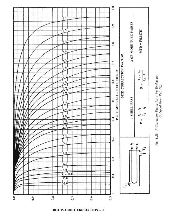
23 The prblem f cmputng an effectve mean temperature dfference fr ths cnfguratn can be carred ut alng lnes very smlar t thse used t btan the LMTD. The basc assumptns are the same (except fr the pure ccurrent r cuntercurrent lmtatn), thugh n addtn t s assumed that each pass has the same amunt f heat transfer area. Rather than calculate the MTD drectly hwever, t s preferable t cmpute a crrectn factr F n the LMTD calculated assumng pure cuntercurrent flw,.e. MTD F = (1.30) LMTD where F = 1 ndcates the flw stuatn s equvalent t cuntercurrent flw, and lwer values very clearly and drectly shw what penalty (ultmately expressed n area requred) s beng pad fr the 1-2 cnfguratn. It s mprtant t remember that the LMTD used n Eq. (1.30) s t be calculated fr the cuntercurrent flw case, Eq. (1.27). The crrectn factr F s shwn n Fg fr a 1-2 exchanger as a functn f tw parameters R and P defned as (n terms f the nmenclature gven n the chart): T1 T2 R = t t 2 t2 t1 P = T t Range f shell flud = Range f tube flud Range f tube flud = Maxmum temperature dfference (1.31a) (1.31b) The chart gven here s adapted frm the Standards f the Tubular Exchanger Manufacturers sscatn (9) and s almst dentcal t the ne n Kern (7). The crrespndng chart n Mcdams (8) uses entrely dfferent symbls, but s n fact dentcal t the ne gven here. Hwever, there are ther dfferent (but fnally equvalent) frmulatns and each ne shuld be used carefully wth ts wn defntns. Examnatn f the chart reveals that fr each value f R, the curve becmes suddenly and extremely steep at sme value f P. Ths s due t the tube-sde temperature apprachng ne f the thermdynamc lmts dscussed abve. It s extremely dangerus t desgn an exchanger n r near ths steep regn, because even a small falure f ne f the basc assumptns can easly render the exchanger thermdynamcally ncapable f renderng the specfed perfrmance n matter hw much excess surface s prvded; the frst assumptn s especally crtcal n ths case. Therefre, there s a generally accepted rule-f-thumb that n exchanger wll be desgned t F < Besdes, lwer values f F result n large addtnal surface requrements and there s almst always sme way t d t better. The dscussn t ths pnt has centered n the 1-2 exchanger. Larger numbers f tube-sde passes are pssble and frequently used. Kern dscusses the prblem brefly and pnts ut that crrectn factrs fr any even number f tube-sde passes are wthn abut 2 percent f thse fr tw passes, s t s cmmn practce t use Fg fr all 1-n exchangers where n s any even number. Other cnfguratns wll be dscussed later. Kern, Mcdams, and Perry's Handbk (10) gve farly extensve cllectns f F charts. 28
24 29
25 2. Multple Shell-Sde Passes. In an attempt t ffset the dsadvantage f values f F less than 1.0 resultng frm the multple tube sde passes, sme manufacturers regularly desgn shell and tube exchangers wth lngtudnal shell-sde baffles as shwn n Fg If ne traces thrugh the flw paths, ne sees that the tw streams are always cuntercurrent t ne anther, therefre superfcally gvng F = 1.0. The prncple culd be extended t multple shell sde passes t match multple tube sde passes but ths s seldm r never dne n practce. Even the prvsn f a sngle shell-sde lngtudnal baffle pses a number f fabrcatn, peratn and mantenance prblems. Wthut dscussng all f the pssbltes, we may bserve that there may be, unless very specal precautns are taken, wll be, thermal leakage frm the ht shell-sde pass thrugh the baffle t the ther (cld) pass, whch vlates the 6th assumptn. Further, there may even be physcal leakage f flud frm the frst shell-sde pass t the secnd because f the pressure dfference, and ths vlates the 1st assumptn. recent analyss has been made f the prblem (Rzenmann and Tabrek, Ref. 11), whch warns ne when the penalty may becme severe. 3. Multple Shells n Seres. If we need t use multple tube sde passes (as we ften d), and f the sngle shell pass cnfguratn results n t lw a value f F (r n fact s thermdynamcally nperable), what can we d? The usual slutn s t use multple shells n seres, as dagrammed n Fg fr a very smple case. Mre than tw tube passes per shell may be used. The use f up t sx shells n seres s qute cmmn, especally n heat recvery trans, but sner r later pressure drp lmts n ne stream r the ther lmt the number f shells. Qualtatvely, we may bserve that the verall flw arrangement f the tw streams s cuntercurrent, even thugh the flw wthn each shell s stll mxed. Snce, hwever, the temperature change f each stream n ne shell s nly a fractn f the ttal change, the departure frm true cuntercurrent flw s less. lttle reflectn wll shw that as the number f shells n seres becmes nfnte, the heat transfer prcess appraches true cunter- current flw and F 1.0. It s pssble t analyze the thermal perfrmance f a seres f shells each havng ne shell pass and an even number f tube passes, by usng heat balances and Fg appled t each shell. Such calculatns quckly becme very tedus and t s much mre cnvenent t use charts derved specfcally fr varus numbers f shells n seres. Such charts are ncluded n Chapter 2 f ths Manual. 30
 (1.")
26 4. The Mean Temperature Dfference n Crssflw Exchangers. Many heat exchangers - especally ar-cled heat exchangers (Fg. 1.32) - are arranged s that ne flud flws crsswse t the ther flud. The mean temperature dfference n crssflw exchangers s calculated n much the same way and usng the same assumptns as fr shell and tube exchangers. That s, MTD = F (LMTD) (1.32) where F s taken frm Fgure 1.33 fr the cnfguratn shwn n Fg Recall that the LMTD s calculated n the bass that the tw streams are n cuntercurrent flw. 31


27 1.4. Cnstructn f Shell and Tube Heat Exchangers Why a Shell and Tube Heat Exchanger? Shell and tube heat exchangers n ther varus cnstructn mdfcatns are prbably the mst wdespread and cmmnly used basc heat exchanger cnfguratn n the prcess ndustres. The reasns fr ths general acceptance are several. The shell and tube heat exchanger prvdes a cmparatvely large rat f heat transfer area t vlume and weght. It prvdes ths surface n a frm whch s relatvely easy t cnstruct n a wde range f szes and whch s mechancally rugged enugh t wthstand nrmal shp fabrcatn stresses, shppng and feld erectn stresses, and nrmal peratng cndtns. There are many mdfcatns f the basc cnfguratn, whch can be used t slve specal prblems. The shell and tube exchanger can be reasnably easly cleaned, and thse cmpnents mst subject t falure - gaskets and tubes can be easly replaced. Fnally, gd desgn methds exst, and the expertse and shp facltes fr the successful desgn and cnstructn f shell and tube exchangers are avalable thrughut the wrld Basc Cmpnents f Shell and Tube Heat Exchangers. Whle there s an enrmus varety f specfc desgn features that can be used n shell and tube exchangers, the number f basc cmpnents s relatvely small. These are shwn and dentfed n Fg Tubes. The tubes are the basc cmpnent f the shell and tube exchanger, prvdng the heat transfer surface between ne flud flwng nsde the tube and the ther flud flwng acrss the utsde f the tubes. The tubes may be seamless r welded and mst cmmnly made f cpper r steel allys. Other allys f nckel, ttanum, r alumnum may als be requred fr specfc applcatns. The tubes may be ether bare r wth extended r enhanced surfaces n the utsde. typcal Trufn Tube wth extended surface s shwn n Fg Extended r enhanced surface tubes are used when ne flud has a substantally lwer heat transfer ceffcent than the ther flud. Dubly enhanced tubes, that s, wth enhancement bth nsde and utsde are avalable that can reduce the sze and cst f the exchanger. Extended surfaces, (fnned tubes) prvde tw t fur tmes as much heat transfer area n the utsde as the crrespndng bare tube, and ths area rat helps t ffset a lwer utsde heat transfer ceffcent. Mre recent develpments are: a crrugated tube whch has bth nsde and utsde heat transfer enhancement, a fnned tube whch has ntegral nsde turbulatrs as well as extended utsde surface, and tubng whch has utsde surfaces desgned t prmte nucleate blng. These and ther develpments are treated n detal n the last chapter f ths bk. 32
28 2. Tube Sheets. The tubes are held n place by beng nserted nt hles n the tube sheet and there ether expanded nt grves cut nt the hles r welded t the tube sheet where the tube prtrudes frm the surface. The tube sheet s usually a sngle rund plate f metal that has been sutably drlled and grved t take the tubes (n the desred pattern), the gaskets, the spacer rds, and the blt crcle where t s fastened t the shell. Hwever, where mxng between the tw fluds (n the event f leaks where the tube s sealed nt the tube sheet) must be avded, a duble tube sheet such as s shwn n Fg may be prvded. The space between the tube sheets s pen t the atmsphere s any leakage f ether flud shuld be quckly detected. Trple tube sheets (t allw each flud t leak separately t the atmsphere wthut mxng) and even mre extc desgns wth nert gas shruds and/r leakage recyclng systems are used n cases f extreme hazard r hgh value f the flud. The tube sheet, n addtn t ts mechancal requrements, must wthstand crrsve attack by bth fluds n the heat exchanger and must be electrchemcally cmpatble wth the tube and all tube-sde materal. Tube sheets are smetmes made frm lw carbn steel wth a thn layer f crrsn-resstng ally metallurgcally bnded t ne sde. 3. Shell and Shell-Sde Nzzles. The shell s smply the cntaner fr the shell-sde flud, and the nzzles are the nlet and ext prts. The shell nrmally has a crcular crss sectn and s cmmnly made by rllng a metal plate f the apprprate dmensns nt a cylnder and weldng the lngtudnal jnt ("rlled shells"). Small dameter shells (up t arund 24 nches n dameter) can be made by cuttng ppe f the desred dameter t the crrect length ("ppe shells"). The rundness f the shell s mprtant n fxng the maxmum dameter f the baffles that can be nserted and therefre the effect f shell-t-baffle leakage. Ppe shells are mre nearly rund than rlled shells unless partcular care s taken n rllng, In rder t mnmze ut-f-rundness, small shells are ccasnally expanded ver a mandrel; n extreme cases, the shell s cast and then bred ut n a brng mll. In large exchangers, the shell s made ut f lw carbn steel wherever pssble fr reasns f ecnmy, thugh ther allys can be and are used when crrsn r hgh temperature strength demands must be met. The nlet nzzle ften has an mpngement plate (Fg. 1.37) set just belw t dvert the ncmng flud jet frm mpactng drectly at hgh velcty n the tp rw f tubes. Such mpact can cause ersn, cavtatns, and/r vbratn. In rder t put the mpngement plate n and stll leave enugh flw area between the shell and plate fr the flw t dscharge wthut excessve pressure lss, t may be necessary t mt sme tubes frm the full crcle pattern. Other mre cmplex arrangements t dstrbute the enterng flw, such as a sltted dstrbutr plate and an enlarged annular dstrbutr sectn, are ccasnally emplyed. 4. Tube-Sde Channels and Nzzles. Tube-sde channels and nzzles smply cntrl the flw f the tube-sde flud nt and ut f the tubes f the exchanger. Snce the tube-sde flud s generally the mre crrsve, these channels 33

29 and nzzles wll ften be made ut f ally materals (cmpatble wth the tubes and tube sheets, f curse). They may be clad nstead f sld ally. 5. Channel Cvers. The channel cvers are rund plates that blt t the channel flanges and can be remved fr tube nspectn wthut dsturbng the tube-sde ppng. In smaller heat exchangers, bnnets wth flanged nzzles r threaded cnnectns fr the tube-sde ppng are ften used nstead f channels and channel cvers. 6. Pass Dvder. pass dvder s needed n ne channel r bnnet fr an exchanger havng tw tube-sde passes, and they are needed n bth channels r bnnets fr an exchanger havng mre than tw passes. If the channels r bnnets are cast, the dvders are ntegrally cast and then faced t gve a smth bearng surface n the gasket between the dvder and the tube sheet. If the channels are rlled frm plate r bult up frm ppe, the dvders are welded n place. The arrangement f the dvders n multple-pass exchangers s smewhat arbtrary, the usual ntent beng t prvde nearly the same number f tubes n each pass, t mnmze the number f tubes lst frm the tube cunt, t mnmze the pressure dfference acrss any ne pass dvder (t mnmze leakage and therefre the vlatn f the MTD dervatn), t prvde adequate bearng surface fr the gasket and t mnmze fabrcatn cmplexty and cst. Sme pass dvder arrangements are shwn n Fg Baffles. Baffles serve tw functns: Mst mprtantly, they supprt the tubes n the prper pstn durng assembly and peratn and prevent vbratn f the tubes caused by flw-nduced eddes, and secndly, they gude the shell-sde flw back and frth acrss the tube feld, ncreasng the velcty and the heat transfer ceffcent. The mst cmmn baffle shape s the sngle segmental, shwn n Fg The segment sheared ff must be less than half f the dameter n rder t nsure that adjacent baffles verlap at least ne full tube rw. Fr lqud flws n the shell sde, a baffle cut f 20 t 25 percent f the dameter s cmmn; fr lw pressure gas flws, 40 t 45 percent (.e., clse t the maxmum allwable cut) s mre cmmn, n rder t mnmze pressure drp. The baffle spacng shuld be crrespndngly chsen t make the free flw areas thrugh the "wndw" (the area between the baffle edge and shell) and acrss the tube bank rughly equal. Fr many hgh velcty gas flws, the sngle segmental baffle cnfguratn results n an undesrably hgh shell-sde pressure drp. One way t retan the structural advantages f the segmental baffle and reduce the pressure drp (and, 34
30 regrettably, t sme extent, the heat transfer ceffcent, t) s t use the duble segmental baffle, shwn n Fg Exact cmparsns must be made n a case-t-case bass, but the rugh effect s t halve the lcal velcty and therefre t reduce the pressure drp by a factr f abut 4 frm a cmparable sze sngle segmental unt. Fr suffcently large unts, t s pssble t g t trple segmental arrangements and ultmately t strp and rd baffles, the mprtant pnt beng always t nsure that every tube s pstvely cnstraned at perdc dstances t prevent saggng and vbratn. Specal prvsns must be made fr supprtng fnned tubes passng thrugh a baffle: 1) prvde unfnned lands (f nrmal bare tube dameter) at the baffles; 2) use baffles thck enugh that several fns fall wthn the baffle thckness and prvde a sld bearng surface r 3) prvde a thn metal wrap utsde the fns n the vcnty f the baffle Prvsns fr Thermal Stress 1. The Thermal Stress Prblem. Snce, by ts very purpse, the shell f the heat exchanger wll be at a sgnfcantly dfferent temperature than tubes, the shell wll expand r cntract relatve t the tubes, resultng n stresses exstng n bth cmpnents and beng transmtted thrugh the tube sheets. The cnsequences f the thermal stress wll vary wth crcumstances, but shells have been buckled r tubes pulled ut f the tube sheet r smply pulled apart. The fxed tube sheet exchanger shwn n Fg s especally vulnerable t ths knd f damage because there s n prvsn made fr accmmdatng dfferental expansn. There s a rugh rule f thumb that says a smple fxed tube sheet cnfguratn can nly be used fr cases where the nlet temperatures f the tw streams d nt dffer by mre than 100 'F. Obvusly, there must be many qualfcatns made t such a flat statement, recgnzng the dfferences n materals and ther prpertes, temperature level f peratn, start-up and cyclng peratnal prcedures, etc. 2. Expansn Jnt n the Shell. The mst bvus slutn t the thermal expansn prblem s t put an expansn rll r jnt n the shell, as shwn n Fg Ths becmes less attractve fr large dameter shells and/r ncreasng shell-sde pressure. Hwever, very large dameter, near-atmspherc pressure shells have been desgned wth a partal ball-jnt n the shell desgned t allw the shell t partally "rtate" t accmmdate stresses. 3. Internal Bellws. In recent years, an nternal bellws desgn (Fg. 1.42) has becme ppular fr such applcatns as waste heat vertcal thermsphn reblers, where nly ne pass s permtted n the tube sde. These bellws have been desgned t perate successfully wth hgh pressure blng water n the tube sde and hgh temperature reactr effluent gas n the shell. 35
31 4. The U-Tube Exchanger. One desgn varatn that allws ndependent expansn f tubes and shell s the U-tube cnfguratn shwn schematcally n Fg Whle ths desgn slves the thermal expansn prblem abut as well as t can be slved, t has sme drawbacks (e.g., nablty t replace ndvdual tubes except n the uter rw, nablty t clean arund the bend) that render t unacceptable fr sme servces. 5. Flatng Head Desgns. Several dfferent desgns f "flatng head" shell and tube exchangers are n cmmn use. The gal n each case, f curse, s t slve the thermal stress prblem and each desgn des accmplsh that gal. Inevtably, hwever, smethng must be gven up, and each cnfguratn has a smewhat dfferent set f drawbacks t be cnsdered when chsng ne. The smplest flatng head desgn s the "pull-thrugh bundle" type, shwn n Fg One f the tube sheets s made small enugh that t and ts gasketed bnnet may be pulled cmpletely thrugh the shell fr shell-sde nspectn and cleanng. The tube sde may be cleaned and ndvdual tubes may be replaced wthut remvng the bundle frm the shell. Unfrtunately, many tubes must be mtted frm the edge f the full bundle t allw fr the bnnet flange and blt crcle. Ths bjectn s met n the "splt-rng flatng head" type (Fg. 1.45) by bltng the flatng head bnnet t a splt backng rng rather than t the tube sheet. t sme cst n added mechancal cmplexty, mst f the tubes lst frm the bundle n the pull-thrugh desgn have been restred, and the ther features retaned. Tw ther types, the "utsde-packed lantern rng," (Fg. 1.46), and the "utsde-packed stuffng bx", (Fg. 1.47) are mre prne t leakage t the atmsphere than the fregng types and gve up the advantage f pstve sealng 36
32 s mprtant n hgh pressure r hazardus flud servce. They have the advantage f allwng sngle tube sde pass desgn Mechancal Stresses 1. Surces f Mechancal Stresses. Every exchanger s subject t mechancal stresses frm a varety f surces n addtn t temperature gradents. There are mechancal stresses whch result frm the cnstructn technques used n the exchanger, e.g., tube and tube sheet stresses resultng frm rllng n the tubes. Durng the manufacture, shppng and nstallatn f the exchanger there are many, frequently unfreseen stresses mpsed. There are stresses caused by the supprt structure reactng t the weght f the exchanger, and stresses frm the cnnectng ppng; these stresses are generally very dfferent durng nrmal plant peratn than durng cnstructn r shutdwn. Fnally, there are the stresses arsng wthn the exchanger as a result f the prcess stream cndtns - especally pressure durng peratn. 2. Prvsn fr Mechancal Stress. T prtect the ex changer frm permanent defrmatn r weakenng frm these mechancal stresses, t s necessary t desgn the exchanger s that any stress that can be reasnably expected t ccur wll nt stran r defrm the metal beynd the pnt where t wll spntaneusly return t ts rgnal cndtn. nd t s necessary t nsure that stresses greater than the desgn values d nt ccur. The analyss f stresses and strans n a heat exchanger s an extremely brad and cmplcated subject, and wll nt be develped n any detal here. The mre bvus prblems can be at least antcpated n a qualtatve way by the thermal desgner wh can then seek the advce f a specalst n the subject The Vbratn Prblem very serus prblem n the mechancal desgn f heat exchangers s flw - nduced vbratn f the tubes. There are several pssble cnsequences f tube vbratn, all f them bad. The tubes may vbrate aganst the baffles, whch can eventually cut hles n the tubes. In extreme cases, the tubes can strke adjacent tubes, lterally knckng hles n each ther. Or the repeated stressng f the tube near a rgd supprt such as a tube sheet can result n fatgue crackng f a tube, lsenng f the tube jnt, and accelerated crrsn. Vbratn s caused by repeated unbalanced frces beng appled t the tube. There are a number f such frces, but the mst cmmn ne n heat exchangers s the eddyng mtn f the flud n the wake f a tube as the flud flws acrss the tube. The unbalanced frces are relatvely small, but they ccur tens, hundreds, r thusands f tmes a secnd, and ther magntudes ncrease rapdly wth ncreased flud velcty. Even s, these frces are rdnarly damped ut wth n damage t the tube. Hwever, any bdy can vbrate much mre easly at certan frequences (called "natural frequences") than at thers. If the unbalanced frces are appled at "drvng frequences" that are at 37
33 r near these natural frequences, resnance ccurs; and even small frces can result n very strng vbratn f the tube. lthugh prgress s beng made, the predctn f whether r nt a gven heat exchanger cnfguratn wll adequately resst vbratn s nt yet a well-develped scence. The tw best ways t avd vbratn prblems are t supprt the tubes as rgdly as pssble (e.g., clse baffle spacng) and t keep the velctes lw. Bth f these ften cnflct wth the desre t keep the cst f the exchanger dwn. Fr the present, experence s the best gude n ths area Ersn nther essentally mechancal prblem n heat exchanger desgn s that f ersn: the rapd remval f metal due t the frctn f the flud flwng n r acrss the tube. Ersn ften ccurs wth and accelerates the effect f crrsn by strppng ff the prtectve flm frmed n certan metals. The ersn rate depends upn the metal (the harder the metal, the less the ersn f ther factrs are equal), the velcty and densty f the flud, and the gemetry f the system. Thus, ersn s usually mre severe at the entrance f a tube r n the bend f a U-tube, due t the addtnal shear stress asscated wth develpng the bundary layer r turnng the flud. Other, mre elusve effects are asscated wth the chemstry f the flud and the tube metal, especally where crrsn s nvlved. There are sme cmmnly used upper velcty lmts fr flw nsde tubes f a gven metal. These lmts are shwn n Table Cst f Shell and Tube Heat Exchangers Sme apprecatn f the cst bass fr shell and tube exchangers s essental t the prper selectn f a cnfguratn and allcatn f streams. It s mpssble t furnsh here a precse and reasnably current crrelatn fr estmatng the cst f a gven cnfguratn, but we may at least dentfy the relatve cntrbutns t the ttal cst and hw these change wth certan desgn specfcatns. The cst f a shell and tube exchanger f..b. the fabrcatn shp s cmpsed f the csts f the ndvdual cmpnents (shell, tubes, etc.), plus the assembly cst. The cst f each cmpnent s the sum f the materal cst, plus grss fabrcatn (e.g., rllng the shell), plus machnng. The fnal prce t the custmer wll als nclude engneerng and ther verheads, the fabrcatr's prft and shppng. Sme f these, e.g. the prft, are rughly prprtnal t the ttal cst, whle the shppng s mre nearly prprtnal t the ttal weght. In rder t arrve at the mst ecnmcal unt (n a frst cst bass), t s necessary t cnsder the effect f the specal requrements f the unt n each f the cmpnent csts. Fr example, suppse ne flud requres a specal ally t resst crrsn. If that flud s put n the shell, bth the shell and the tubes must be made f that ally; cnversely, f the crrsve flud s put n the tubes, nly the tubes and tube sde fttngs must be ally, and that cst can ften be further reduced f the tube sheets and channels are nly faced wth the ally. The same ttal heat transfer area may be put n a shell that s f small dameter and relatvely lng, r n ne that has a larger dameter and shrter length. The cst f a shell - ften the largest sngle cst n the ttal exchanger cst - ncreases very rapdly wth dameter but nly lnearly (at mst) wth length. Therefre, unless space r pressure drp lmts dctate therwse, the mst ecnmcal exchanger s usually ne f relatvely large length t dameter rat - up t perhaps 12 t I fr a very rugh rule f thumb. 38
34 Fr the exchanger as a whle, nly a cmplete cst analyss f several dfferent desgns can establsh whch s n fact the least expensve n frst cst. There are hwever, a number f rules, whch wll tend t select the mre ecnmcal desgns ut f the multtude f pssbltes. These wll be dscussed further llcatn f Streams n a Shell and Tube Exchanger In prncple, ether stream enterng a shell and tube ex changer may be put n ether sde-tube-sde r shell-sde -f the surface. Hwever, there are fur cnsderatns, whch exert a strng nfluence upn whch chce wll result n the mst ecnmcal exchanger: 1. Hgh pressure: If ne f the streams s at a hgh pressure, t s desrable t put that stream nsde the tubes. In ths case, nly the tubes and the tube-sde fttngs need be desgned t wthstand the hgh pressure, whereas the shell may be made f lghter weght metal. Obvusly, f bth streams are at hgh pressure, a heavy shell wll be requred and ther cnsderatns wll dctate whch flud ges n the tube. In any case, hgh shell sde pressure puts a premum n the desgn f lng, small dameter exchangers. 2. Crrsn: Crrsn generally dctates the chce f materal f cnstructn, rather than exchanger desgn. Hwever, snce mst crrsn - resstant allys are mre expensve than the rdnary materals f cnstructn, the crrsve flud wll rdnarly be placed n the tubes s that at least the shell need nt be made f crrsn - resstant materal. If the crrsn cannt be effectvely prevented but nly slwed by chce f materal, a desgn must be chsen n whch crrdble cmpnents can be easly replaced (unless t s mre ecnmcal t scrap the whle unt and start ver.) 3. Fulng: Fulng enters nt the desgn f almst every prcess exchanger t a measurable extent, but certan streams ful s badly that the entre desgn s dmnated by features whch seek a) t mnmze fulng (e.g. hgh velcty, avdance f dead r eddy flw regns) b) t facltate cleanng (fulng flud n tube-sde, wde ptch and rtated square layut f shell-sde flud s fulng) r c) t extend peratnal lfe by multple unts. 4. Lw heat transfer ceffcent: If ne stream has an nherently lw heat transfer ceffcent (such as lw pressure gases r vscus lquds), ths stream s preferentally put n the shell-sde s that extended surface may be used t reduce the ttal cst f the heat exchanger. 39
 shws that, f any ne f the terms n the denmnatr n the rght hand sde s substantally larger than the thers, t essentally fxes the value f U.")
35 1.5. pplcatn f Extended Surfaces t Heat Exchangers The Cncept f the Cntrllng Resstance Examnatn f Eqs. (1.18), (1.19), r (1.20) shws that, f any ne f the terms n the denmnatr n the rght hand sde s substantally larger than the thers, t essentally fxes the value f U. Snce each f these terms s a resstance t heat transfer, the term that dmnates s called the "cntrllng resstance," and the desgner needs t devte partcular attentn t ts value. s nted n the prevus sectn, ne heat transfer ceffcent may be much lwer than the ther, and ths ceffcent s the ne that leads t a hgh resstance fr heat transfer. Thus, a lw ceffcent crrespnds t a hgh, and frequently cntrllng, resstance. One way t mnmze the adverse effects f a lw heat transfer ceffcent s t place that stream n the shell sde f a heat exchanger and use extended surface t ncrease the rat f the utsde t nsde area ( / ) t ffset the lw value f h Types f Extended Surface "Extended surface" s a term that cvers many pssbltes but the type that we shall be mst cncerned wth s the rund tube wth rund fns essentally transverse t the tube axs. Typcal ntegral fnned tubes are shwn n Fg The lw-fnned tube cmmnly used n shell and tube exchangers prvdes abut 3 t 4 tmes as much utsde area as nsde;.e., / s abut 3 t 4. In the Wlverne S/T type, fn cunts f 16 t 40 per nch are avalable. The utsde dameter f the fns s just slghtly less than that f the bare tube at the ends, s the tube can be nserted thrugh the tube sheet hles. The wall under the fns s cntrlled t a specfed thckness, and the wall at the plan ends s abut tw gauges heaver. Fr tube supprt at baffles, unfnned sectns ("lands") are avalable. medum-fn heght tube wth 11 fns per nch s als used n shell and tube exchangers, and has an / rat typcally abut 5. The hgh-fn tube s used t advantage when gases are t Fg Several types f Wlverne Trufn Tubng be heated r cled r when a prcess stream s t be ar-cled. Hgh-fn tubes cme n a wde varety f fn heghts, thcknesses, and spacngs, gvng values f / up t 25. Fr crrsn prtectn, a mechancally bnded lner tube may be used nsde the fnned tube. The lner can be made f crrsn-resstant ally, whle the uter tube and fns are made f a hgh cnductvty metal such as cpper r alumnum t mprve heat transfer. ll f the fnned tubes prduced by Wlverne have ntegral fns,.e., the fns are frmed frm the base tube by an extrusn prcess s that the fnal tube and ts fns are ne pece f metal. Fr hgh-fnned tubes, ther fn types exst n whch the fn s a separate pece f metal wrapped n the tube. The fn s usually held n place nly by the tensn f the defrmed fn metal r ccasnally by slderng, weldng r brazng the fn t the tube. In these fnned tubes, cntact resstance between the fn and the tube s an mprtant cnsderatn. Even f the fn s rgnally n gd thermal cntact, repeated thermal cyclng can result n creep and partal separatn f the 40
36 fn. ls, the crevce between fn and tube prvdes a pssble ste fr crrsn wth cnsequent ncrease n cntact resstance and pssbly accelerated falure f the tube Fn Effcences and Related Cncepts Cnsderatn f the heat flw path frm the tube-sde flud thrugh the tube wall, and fns, and nt the fn sde flud reveals that the dstance whch the heat must flw' s lnger than n the crrespndng plan tube case. It s true that the addtnal dstance s thrugh the usually hghly cnductve fn metal, but there s stll an addtnal resstance t the flw f heat, whch partally ffsets the advantage f the extended surface. In rder t take accunt f ths resstance n ur calculatns, we defne a "fn effcency, " φ, n the fllwng manner: φ s the rat f the ttal heat transferred frm the actual fn t the ttal heat that wuld be transferred f the fn were sthermal at ts base temperature. Ths defntn s llustrated by Fg In ths fgure, the fn temperature T f s hgher than the bulk uter flud temperature, T, s heat flws frm the fn t the uter flud. ll the heat thus transferred hwever must flw nt the fn thrugh the base r rt f the fn. Therefre, the temperature at the base f the fn, T r, s the hghest temperature n the fn. The temperature decreases cntnuusly frm that pnt as ne prceeds utward n the fn n rder t cause the heat t flw frm the base t the fn. The rate f decrease depends upn the shape and thermal cnductvty f the fn and the flm heat transfer ceffcent frm the fn t the uter flud. It s clear that the maxmum amunt f heat wuld be transferred frm the fn f the fn were everywhere at T r, and that culd nly happen f the fn metal had nfnte thermal cnductvty. N metal has nfnte thermal cnductvty, f curse, but ths makes a cnvenent reference pnt aganst whch real fns can be cmpared, as n the abve defntn f fn effcency. cmplex mathematcal analyss s necessary t btan a slutn fr the fn effcency, and ths wll nt be carred ut here. very cmplete dscussn f the prblem and t slutns s gven n the bk, "Extended Surface Heat Transfer", by Kern and Kraus (12). Fr the knds f fns that are cnsdered here, a gd equatn t use ver mst f the range f nterest s: where 1 Φ = (1.33) 2 m d d r m = H 1 h 2 + R f ky (1.34) 41
37 The gemetrcal varables are defned n Fg. 1.50, and h and R f are respectvely the actual cnvectve heat transfer ceffcent and the actual fulng resstance n the fn sde, based n the fn area. n nspectn f Eqs. (1.33) and (1.34) ndcates that the fn effcency s hgher fr the better-cnductng fn materals, and hgher as the utsde heat transfer ceffcent s lwer. Fnned tubes are nt generally used n applcatns where the fn effcency s less than The fn effcency s applcable nly t the fn area f the tube. It s assumed that heat s transferred frm the rt area f the tube (between the fns) wth an effcency f Thus, we may wrte the equatn fr the ttal heat transfer frm the tube as: ( T T ) + h ( T T )Φ Q (1.35) = h rt r fn r where rt refers t the heat transfer area f the rt prtns between the fns and fn t the heat transfer area f all the fns n the tube. Ths equatn may be wrtten as: r ( T T )( + Φ ) Q = h (1.36) r ( T r T ) eq rt fn Q = h (1.37) where eq, the equvalent r effectve heat transfer area, s eq = + Φ (1..38) rt fn If the utsde f the tube (ncludng the fns) has a fulng flm n t, Eqs. (1.35), (1.36) and (1.37) must be wrtten: r r Q R h R h ( T T ) + ( T T )Φ = rt r fn r Q 1 = 1 + R h Q 1 = 1 + R h f f f ( T T )( + Φ ) r ( T r T ) eq rt fn f (1.39) (1.40) (1.41) 42
 rt + fn and values f ths rat can be calculated fr a gven tube as a functn f materal and 1 + R f nce and fr all. Ths has been h dne n Fgures 1.51 a, b, c fr the Wlverne Trufn Prducts.")
38 and Eq. (1.38) s unchanged. eq may be dvded by the ttal utsde heat transfer area f the tube t gve a weghted fn effcency. E + Φ rt fn w = (1.42) rt + fn and values f ths rat can be calculated fr a gven tube as a functn f materal and 1 + R f nce and fr all. Ths has been h dne n Fgures 1.51 a, b, c fr the Wlverne Trufn Prducts. 1 1 / h + f f, Btu / Hr. SQ. FT F Fg. 1.51a Weghted Fn Effcency f 19 Fn Type S/T Trufn The Fn Resstance Methd nther way f representng the heat transfer effectveness f a fnned tube s by the "fn resstance methd," as frst develped by Carrer and ndersn (13) and further mdfed by Yung and Ward (14). Ths s the methd that wll be generally used n the remander f ths Manual. The lne f argument that led t Eq. (1.16) was based upn a plan tube n whch all f the uter heat transfer was taken t be equvalent n ts ablty t transfer heat. The valdty f that equatn may be extended t fnned tubes f we rewrte the equatn ntrducng an addtnal resstance due t heat cnductn thrugh the fn, R fn : T T Q = (1.43) 1 R f Δx R w fn R f h k h w m The thrd term n the denmnatr, referrng t the wall resstance, s evaluated fr that prtn f the tube wall that les between the nsde dameter and the rt dameter,.e., exclusve f the fns. Thus and ( ) Δx = 1/ 2 d r d (1.44) m π ( d + Δx)L (1.45) We nw defne an verall heat transfer ceffcent U based n the entre uter surface f the fnned tube, : Q = U ( T T ) (1.46) 1 1/ h + f f, Btu / Hr. SQ. FT F Fg 1.51b. Weghted Fn Effcences f 26 and 28 Fn Type S/T Trufn 43
 s wrtten, each term n the rght-hand-sde s a resstance t heat transfer fr the partcular prcess nvlved; the temperature drp acrss each part f the prcess s prprtnal t the magntude f the crrespndng")
39 Elmnatng Q and ( T ) between Eqs. (1.43) and (1.46) and rearrangng, we have: T 1 U 1 = h + R f + R fn Δx + k w m + R f 1 + h (1.47) s wrtten, each term n the rght-hand-sde s a resstance t heat transfer fr the partcular prcess nvlved; the temperature drp acrss each part f the prcess s prprtnal t the magntude f the crrespndng resstance. If we take the frst three terms n the rght sde f Eq. (1.47), the crrespndng temperature drp s that frm the rt t the external flud, T T ), and the crrespndng heat flw s ( r ( T T ) r Q = 1 + R h f + R fn (1.48) Ths may be equated t Eq. (1.40) whch uses the fn effcency Φ, but whch must gve the same heat flw. Wth sme rearrangement 1, Btu / Hr. SQ. FT F 1/ h + f f Fg.1.51c Weghted Fn Effcences f 32 & 40 Fn Type S/T Trufn R fn 1 Φ 1 + R rt h + Φ fn = f (1.49) Usng Eqs. (1.33, 1.34) t evaluate Φ, R fn 1 may be calculated as a functn f + R f h fr varus fn materals and gemetres: results are gven n Fgures 1.52a, b, c fr the standard Wlverne Trufn Prducts. n mprtant feature f R fn s that t s nearly cnstant fr a gven fn gemetry and materal ut t hgh values f the abscssa (relatve t the usual range f fnned tube applcatn.) 1 1/ h + r f, Btu/ HR. SQ. FT F Fg. 1.52a Fn Resstance f 19 Fn Type S/T Trufn 44


40 Fg.1.52b Fn Resstance f 26 & 27 Fn Type S/T Trufn Fg. 1.52c Fn Resstance f 32 & 40 Fn Type S/T Trufn Sme pplcatns f Fnned Tubes. One majr applcatn f hgh-fnned tubes s n ar-cled heat exchangers. tmspherc ar, lke all lw pressure gases, gves a very lw heat transfer ceffcent at nrmal velctes. By cntrast, the tube-sde flud, usually a lqud t be sensbly cled r a vapr t be cndensed may have a ceffcent up t 100 tmes hgher, r even mre. Therefre, hgh-fnned tubes are used n these exchangers t reduce the verall sze f exchanger requred. Even s, sme f these nstallatns cver several acres. Cnstructn detals and desgn methds fr ths knd f heat exchanger are gven n Chapter 4 f ths manual. Lw- and medum-fnned tubes are used n a varety f sensble, cndensng, and blng servces n shell and tube exchangers. typcal sensble heat transfer applcatn wuld be clng a cmpressed gas n a cmpressr ntercler, usng clng water n the tubes. Lw-fnned tubes are used fr cndensng rganc vaprs, whch have cndensng ceffcents nly a thrd r a quarter f that f the clng water nsde the tubes. In addtn t prvdng addtnal heat transfer area, the fns prvde drp pnts that facltate the dranage f the cndensate. On the ther hand, fnned tubes are nt used fr cndensng steam r ther hgh surface tensn fluds n the fn sde. The hgh surface tensn causes the lqud t hang n the surface, largely nsulatng t by a statc flm f lqud. Fnned tubes are als used n blng servces, especally when cndensng steam s the heatng medum nsde the tubes. The cndensng ceffcent n ths case may be 2000 r 3000 Btu/hr.ft 2.F, s even the hgh heat transfer ceffcents cmmnly asscated wth nucleate blng may be relatvely small by cmparsn, and the desgn can beneft by the use f lw-fnned tubes. 45
Lecture 12. Heat Exchangers. Heat Exchangers Chee 318 1
 Lecture 2 Heat Exchangers Heat Exchangers Chee 38 Heat Exchangers A heat exchanger s used t exchange heat between tw fluds f dfferent temperatures whch are separated by a sld wall. Heat exchangers are
Chapter 3, Solution 1C.
 COSMOS: Cmplete Onlne Slutns Manual Organzatn System Chapter 3, Slutn C. (a If the lateral surfaces f the rd are nsulated, the heat transfer surface area f the cylndrcal rd s the bttm r the tp surface
Chapter 7. Systems 7.1 INTRODUCTION 7.2 MATHEMATICAL MODELING OF LIQUID LEVEL SYSTEMS. Steady State Flow. A. Bazoune
 Chapter 7 Flud Systems and Thermal Systems 7.1 INTODUCTION A. Bazune A flud system uses ne r mre fluds t acheve ts purpse. Dampers and shck absrbers are eamples f flud systems because they depend n the
Conduction Heat Transfer
 Cnductn Heat Transfer Practce prblems A steel ppe f cnductvty 5 W/m-K has nsde and utsde surface temperature f C and 6 C respectvely Fnd the heat flw rate per unt ppe length and flux per unt nsde and per
Transient Conduction: Spatial Effects and the Role of Analytical Solutions
 Transent Cnductn: Spatal Effects and the Rle f Analytcal Slutns Slutn t the Heat Equatn fr a Plane Wall wth Symmetrcal Cnvectn Cndtns If the lumped capactance apprxmatn can nt be made, cnsderatn must be
Physic 231 Lecture 33
 Physc 231 Lecture 33 Man pnts f tday s lecture: eat and heat capacty: Q cm Phase transtns and latent heat: Q Lm ( ) eat flw Q k 2 1 t L Examples f heat cnductvty, R values fr nsulatrs Cnvectn R L / k Radatn
_J _J J J J J J J J _. 7 particles in the blue state; 3 particles in the red state: 720 configurations _J J J _J J J J J J J J _
 Dsrder and Suppse I have 10 partcles that can be n ne f tw states ether the blue state r the red state. Hw many dfferent ways can we arrange thse partcles amng the states? All partcles n the blue state:
Shell Stiffness for Diffe ent Modes
 Engneerng Mem N 28 February 0 979 SUGGESTONS FOR THE DEFORMABLE SUBREFLECTOR Sebastan vn Herner Observatns wth the present expermental versn (Engneerng Dv nternal Reprt 09 July 978) have shwn that a defrmable
CIRCLE YOUR DIVISION: Div. 1 (9:30 am) Div. 2 (11:30 am) Div. 3 (2:30 pm) Prof. Ruan Prof. Naik Mr. Singh
 Div. 2 (11:30 am) Div. 3 (2:30 pm) Prof. Ruan Prof. Naik Mr. Singh") Frst CIRCLE YOUR DIVISION: Dv. 1 (9:30 am) Dv. (11:30 am) Dv. 3 (:30 m) Prf. Ruan Prf. Na Mr. Sngh Schl f Mechancal Engneerng Purdue Unversty ME315 Heat and Mass ransfer Eam #3 Wednesday Nvember 17 010
Frst CIRCLE YOUR DIVISION: Dv. 1 (9:30 am) Dv. (11:30 am) Dv. 3 (:30 m) Prf. Ruan Prf. Na Mr. Sngh Schl f Mechancal Engneerng Purdue Unversty ME315 Heat and Mass ransfer Eam #3 Wednesday Nvember 17 010
3-42. Chapter 15 Steady Heat Conduction. Heat Conduction in Cylinders and Spheres
 Chapter 5 Steady Heat Cnductn Heat Cnductn n Cylnders and Spheres 3-64C When the dameter f cylnder s very small cmpared t ts length, t can be treated as an ndefntely lng cylnder. Cylndrcal rds can als
CHAPTER 3 ANALYSIS OF KY BOOST CONVERTER
 70 CHAPTER 3 ANALYSIS OF KY BOOST CONERTER 3.1 Intrductn The KY Bst Cnverter s a recent nventn made by K.I.Hwu et. al., (2007), (2009a), (2009b), (2009c), (2010) n the nn-slated DC DC cnverter segment,
V. Electrostatics Lecture 27a: Diffuse charge at electrodes
 V. Electrstatcs Lecture 27a: Dffuse charge at electrdes Ntes by MIT tudent We have talked abut the electrc duble structures and crrespndng mdels descrbng the n and ptental dstrbutn n the duble layer. Nw
Department of Civil Engineering & Applied Mechanics McGill University, Montreal, Quebec Canada
 Department f Cvl Engneerng & Appled Mechancs McGll Unversty, Mntreal, Quebec Canada CIVE 90 THEMODYNAMICS & HEAT TANSFE Assgnment #6 SOUTIONS. Cnsder a.-m hgh and -m-wde duble-pane wndw cnsstng f tw 3-mmthck
Analytical Modeling of Natural Convection in Horizontal Annuli
 Analytcal Mdelng f Natural Cnvectn n Hrzntal Annul Peter Teertstra, M. Mchael Yvanvch, J. Rchard Culham Mcrelectrncs Heat Transfer Labratry Department f Mechancal Engneerng Unversty f Waterl Waterl, Ontar,
SIMULATION OF THREE PHASE THREE LEG TRANSFORMER BEHAVIOR UNDER DIFFERENT VOLTAGE SAG TYPES
 SIMULATION OF THREE PHASE THREE LEG TRANSFORMER BEHAVIOR UNDER DIFFERENT VOLTAGE SAG TYPES Mhammadreza Dlatan Alreza Jallan Department f Electrcal Engneerng, Iran Unversty f scence & Technlgy (IUST) e-mal:
6. ELUTRIATION OF PARTICLES FROM FLUIDIZED BEDS
 6. ELUTRIATION OF PARTICLES FROM FLUIDIZED BEDS Elutratn s the prcess n whch fne partcles are carred ut f a fludzed bed due t the flud flw rate passng thrugh the bed. Typcally, fne partcles are elutrated
Feedback Principle :-
 Feedback Prncple : Feedback amplfer s that n whch a part f the utput f the basc amplfer s returned back t the nput termnal and mxed up wth the nternal nput sgnal. The sub netwrks f feedback amplfer are:
Chapter 6 : Gibbs Free Energy
 Wnter 01 Chem 54: ntrductry hermdynamcs Chapter 6 : Gbbs Free Energy... 64 Defntn f G, A... 64 Mawell Relatns... 65 Gbbs Free Energy G(,) (ure substances)... 67 Gbbs Free Energy fr Mtures... 68 ΔG f deal
Spring 2002 Lecture #17
 1443-51 Sprng 22 Lecture #17 r. Jaehn Yu 1. Cndtns fr Equlbrum 2. Center f Gravty 3. Elastc Prpertes f Slds Yung s dulus Shear dulus ulk dulus Tday s Hmewrk Assgnment s the Hmewrk #8!!! 2 nd term eam n
Wp/Lmin. Wn/Lmin 2.5V
 UNIVERITY OF CALIFORNIA Cllege f Engneerng Department f Electrcal Engneerng and Cmputer cences Andre Vladmrescu Hmewrk #7 EEC Due Frday, Aprl 8 th, pm @ 0 Cry Prblem #.5V Wp/Lmn 0.0V Wp/Lmn n ut Wn/Lmn.5V
Introduction to Electronic circuits.
 Intrductn t Electrnc crcuts. Passve and Actve crcut elements. Capactrs, esstrs and Inductrs n AC crcuts. Vltage and current dvders. Vltage and current surces. Amplfers, and ther transfer characterstc.
BME 5742 Biosystems Modeling and Control
 BME 5742 Bsystems Mdeln and Cntrl Cell Electrcal Actvty: In Mvement acrss Cell Membrane and Membrane Ptental Dr. Zv Rth (FAU) 1 References Hppensteadt-Peskn, Ch. 3 Dr. Rbert Farley s lecture ntes Inc Equlbra
PHYSICS 536 Experiment 12: Applications of the Golden Rules for Negative Feedback
 PHYSICS 536 Experment : Applcatns f the Glden Rules fr Negatve Feedback The purpse f ths experment s t llustrate the glden rules f negatve feedback fr a varety f crcuts. These cncepts permt yu t create
Chem 204A, Fall 2004, Mid-term (II)
") Frst tw letters f yur last name Last ame Frst ame McGll ID Chem 204A, Fall 2004, Md-term (II) Read these nstructns carefully befre yu start tal me: 2 hurs 50 mnutes (6:05 PM 8:55 PM) 1. hs exam has ttal
Frst tw letters f yur last name Last ame Frst ame McGll ID Chem 204A, Fall 2004, Md-term (II) Read these nstructns carefully befre yu start tal me: 2 hurs 50 mnutes (6:05 PM 8:55 PM) 1. hs exam has ttal
Section 3: Detailed Solutions of Word Problems Unit 1: Solving Word Problems by Modeling with Formulas
 Sectn : Detaled Slutns f Wrd Prblems Unt : Slvng Wrd Prblems by Mdelng wth Frmulas Example : The factry nvce fr a mnvan shws that the dealer pad $,5 fr the vehcle. If the stcker prce f the van s $5,, hw
PT326 PROCESS TRAINER
 PT326 PROCESS TRAINER 1. Descrptn f the Apparatus PT 326 Prcess Traner The PT 326 Prcess Traner mdels cmmn ndustral stuatns n whch temperature cntrl s requred n the presence f transprt delays and transfer
Circuits Op-Amp. Interaction of Circuit Elements. Quick Check How does closing the switch affect V o and I o?
 Crcuts Op-Amp ENGG1015 1 st Semester, 01 Interactn f Crcut Elements Crcut desgn s cmplcated by nteractns amng the elements. Addng an element changes vltages & currents thrughut crcut. Example: clsng a
element k Using FEM to Solve Truss Problems
 sng EM t Slve Truss Prblems A truss s an engneerng structure cmpsed straght members, a certan materal, that are tpcall pn-ned at ther ends. Such members are als called tw-rce members snce the can nl transmt
Conservation of Energy
 Cnservatn f Energy Equpment DataStud, ruler 2 meters lng, 6 n ruler, heavy duty bench clamp at crner f lab bench, 90 cm rd clamped vertcally t bench clamp, 2 duble clamps, 40 cm rd clamped hrzntally t
CTN 2/23/16. EE 247B/ME 218: Introduction to MEMS Design Lecture 11m2: Mechanics of Materials. Copyright 2016 Regents of the University of California
 Vlume Change fr a Unaxal Stress Istrpc lastcty n 3D Istrpc = same n all drectns The cmplete stress-stran relatns fr an strpc elastc Stresses actng n a dfferental vlume element sld n 3D: (.e., a generalzed
Phys 344 Ch 5 Lect 4 Feb 28 th,
 hys 44 Ch 5 Lect 4 Feb 8 th, 009 1 Wed /4 Fr /6 Mn /9 Wed /11 Fr / 1 55 Dlute Slutn 56 Chemcal Equlbrum Revew Exam (C 107 S 60, 61 Bltzmann Statstcs Bnus: hys Sr hess resentatns @ 4pm HW17: 7,76,8 HW18:8,84,86,88,89,91
Water vapour balance in a building moisture exposure for timber structures
 Jnt Wrkshp f COST Actns TU1 and E55 September 21-22 9, Ljubljana, Slvena Water vapur balance n a buldng msture expsure fr tmber structures Gerhard Fnk ETH Zurch, Swtzerland Jchen Köhler ETH Zurch, Swtzerland
MODULE 7 HEAT EXCHANGERS
 MODULE 7 HEAT EXCHANGERS 7. What are heat exchangers? Heat exchangers are practcal devces used t transfer energy frm ne flud t anther. Arund the husehld, we are accustmed t seeng the cndensers and evapratrs
Thermodynamics of Materials
 Thermdynamcs f Materals 14th Lecture 007. 4. 8 (Mnday) FUGACITY dg = Vd SdT dg = Vd at cnstant T Fr an deal gas dg = (RT/)d = RT dln Ths s true fr deal gases nly, but t wuld be nce t have a smlar frm fr
A/2 l,k. Problem 1 STRATEGY. KNOWN Resistance of a complete spherical shell: r rk. Inner and outer radii
 Prblem 1 STRATEGY KNOWN Resstance f a cmplete sphercal shell: R ( r r / (4 π r rk sphere Inner an uter ra r an r, SOLUTION Part 1: Resstance f a hemsphercal shell: T calculate the resstance f the hemsphere,
Approach: (Equilibrium) TD analysis, i.e., conservation eqns., state equations Issues: how to deal with
 TD analysis, i.e., conservation eqns., state equations Issues: how to deal with") Schl f Aerspace Chemcal D: Mtvatn Prevus D Analyss cnsdered systems where cmpstn f flud was frzen fxed chemcal cmpstn Chemcally eactng Flw but there are numerus stuatns n prpulsn systems where chemcal
Schl f Aerspace Chemcal D: Mtvatn Prevus D Analyss cnsdered systems where cmpstn f flud was frzen fxed chemcal cmpstn Chemcally eactng Flw but there are numerus stuatns n prpulsn systems where chemcal
CHAPTER 3: FEEDBACK. Dr. Wan Mahani Hafizah binti Wan Mahmud
 CHPTER 3: FEEDBCK Dr. Wan Mahan Hafzah bnt Wan Mahmud Feedback ntrductn Types f Feedback dvantages, Characterstcs and effect f Negatve Feedback mplfers Crcuts wth negatve feedback Pstve feedback and Oscllatr
IGEE 401 Power Electronic Systems. Solution to Midterm Examination Fall 2004
 Jós, G GEE 401 wer Electrnc Systems Slutn t Mdterm Examnatn Fall 2004 Specal nstructns: - Duratn: 75 mnutes. - Materal allwed: a crb sheet (duble sded 8.5 x 11), calculatr. - Attempt all questns. Make
Design of Analog Integrated Circuits
 Desgn f Analg Integrated Crcuts I. Amplfers Desgn f Analg Integrated Crcuts Fall 2012, Dr. Guxng Wang 1 Oerew Basc MOS amplfer structures Cmmn-Surce Amplfer Surce Fllwer Cmmn-Gate Amplfer Desgn f Analg
A Proposal of Heating Load Calculation considering Stack Effect in High-rise Buildings
 A Prpsal f Heatng Lad Calculatn cnsderng Stack Effect n Hgh-rse Buldngs *Dsam Sng 1) and Tae-Hyuk Kang 2) 1) Department f Archtectural Engneerng, Sungkyunkwan Unversty, 2066 Sebu-r, Jangan-gu, Suwn, 440-746,
The Effect Of Type-III Antifreeze Proteins (AFPs) On CO2 Hydrate Slurry Formation
 On CO2 Hydrate Slurry Formation") Purdue Unversty Purdue e-pubs Internatnal Refrgeratn and Ar Cndtnng Cnference Schl f Mechancal Engneerng 2014 The Effect Of Type-III Antfreeze Prtens (AFPs) On CO2 Hydrate Slurry Frmatn Hngxa Zhu Delft
Purdue Unversty Purdue e-pubs Internatnal Refrgeratn and Ar Cndtnng Cnference Schl f Mechancal Engneerng 2014 The Effect Of Type-III Antfreeze Prtens (AFPs) On CO2 Hydrate Slurry Frmatn Hngxa Zhu Delft
Problem Set 5 Solutions - McQuarrie Problems 3.20 MIT Dr. Anton Van Der Ven
 Prblem Set 5 Slutns - McQuarre Prblems 3.0 MIT Dr. Antn Van Der Ven Fall Fall 003 001 Prblem 3-4 We have t derve the thermdynamc prpertes f an deal mnatmc gas frm the fllwng: = e q 3 m = e and q = V s
Comparison of Building Codes and Insulation in China and Iceland
 Prceedngs Wrld Gethermal Cngress 00 Bal, Indnesa, 5-9 prl 00 Cmparsn f Buldng Cdes and Insulatn n Chna and Iceland Hayan Le and Pall Valdmarssn Tanjn Gethermal esearch & Tranng Centre, Tanjn Unversty,
55:041 Electronic Circuits
 55:04 Electrnc Crcuts Feedback & Stablty Sectns f Chapter 2. Kruger Feedback & Stablty Cnfguratn f Feedback mplfer S S S S fb Negate feedback S S S fb S S S S S β s the feedback transfer functn Implct
A New Method for Solving Integer Linear. Programming Problems with Fuzzy Variables
 Appled Mathematcal Scences, Vl. 4, 00, n. 0, 997-004 A New Methd fr Slvng Integer Lnear Prgrammng Prblems wth Fuzzy Varables P. Pandan and M. Jayalakshm Department f Mathematcs, Schl f Advanced Scences,
Study Group Report: Plate-fin Heat Exchangers: AEA Technology
 Study Grup Reprt: Plate-fin Heat Exchangers: AEA Technlgy The prblem under study cncerned the apparent discrepancy between a series f experiments using a plate fin heat exchanger and the classical thery
Natural Convection in a Horizontal Annulus with Oscillating Inner Cylinder Using Lagrangian-Eulerian Kinematics
 Natural Cnvectn n a Hrzntal Annulus wth Oscllatng Inner Cylnder Usng Lagrangan-Euleran Knematcs Esam M. Alawadh Kuwat Unversty Mechancal Engneerng Department P. O. Bx # 5969, Safat, 3060 KUWAIT Abstract
Regression with Stochastic Regressors
 Sectn 9 Regressn wth Stchastc Regressrs Meanng f randm regressrs Untl nw, we have assumed (aganst all reasn) that the values f x have been cntrlled by the expermenter. Ecnmsts almst never actually cntrl
4DVAR, according to the name, is a four-dimensional variational method.
 4D-Varatnal Data Assmlatn (4D-Var) 4DVAR, accrdng t the name, s a fur-dmensnal varatnal methd. 4D-Var s actually a smple generalzatn f 3D-Var fr bservatns that are dstrbuted n tme. he equatns are the same,
Section 10 Regression with Stochastic Regressors
 Sectn 10 Regressn wth Stchastc Regressrs Meanng f randm regressrs Untl nw, we have assumed (aganst all reasn) that the values f x have been cntrlled by the expermenter. Ecnmsts almst never actually cntrl
2 Analysis of the non-linear aerodynamic loads of hypersonic flow. 1 General Introduction
 4 TH INTERNATIONAL CONGRESS OF THE AERONAUTICAL SCIENCES PRELIMINARY STUDY OF NON-LINEAR AEROELASTIC PHENOMENA IN HYPERSONIC FLOW Zhang Wewe, Ye Zhengyn, Yang Yngnan Cllege f Aernautcs, Nrthwestern Plytechncal
A method of constructing rock-analysis diagrams a statistical basks.
 130 A methd f cnstructng rck-analyss dagrams a statstcal basks. 0T~ By W. ALF~.D ll~ch).ra)so.~, ~.Se., B.Se. (Eng.), F.G.S. Lecturer n Petrlgy, Unversty Cllege, Nttngham. [Read January 18, 1921.] D R.
4.8 Degradation of Elastomers by Heat and/or Radiation
 4.8 Degradatn f Elastmers by Heat and/r Radatn M.It Japan Atmc Energy Research Insttute, Nuclear Educatn Center 2-28-49, Hnkmagme, Bunkyu-ku Tky, 113, JAPAN Abstract Ths artcle studed sme prblems n the
Lucas Imperfect Information Model
 Lucas Imerfect Infrmatn Mdel 93 Lucas Imerfect Infrmatn Mdel The Lucas mdel was the frst f the mdern, mcrfundatns mdels f aggregate suly and macrecnmcs It bult drectly n the Fredman-Phels analyss f the
Week3, Chapter 4. Position and Displacement. Motion in Two Dimensions. Instantaneous Velocity. Average Velocity
 Week3, Chapter 4 Moton n Two Dmensons Lecture Quz A partcle confned to moton along the x axs moves wth constant acceleraton from x =.0 m to x = 8.0 m durng a 1-s tme nterval. The velocty of the partcle
Computer Aided Design (CAD) of a Multi-component Condenser
 of a Multi-component Condenser") S. BANDYOPADHYAY et al., Cputer Aded Desgn (CAD) f a Mult-cpnent, Che. Bche. Eng. Q. 21 (2) 97 103 (2007) 97 Cputer Aded Desgn (CAD) f a Mult-cpnent Cndenser S. Bandypadhyay, M. S. Ala, V. K. Agrawal,
S. BANDYOPADHYAY et al., Cputer Aded Desgn (CAD) f a Mult-cpnent, Che. Bche. Eng. Q. 21 (2) 97 103 (2007) 97 Cputer Aded Desgn (CAD) f a Mult-cpnent Cndenser S. Bandypadhyay, M. S. Ala, V. K. Agrawal,
Principles of Food and Bioprocess Engineering (FS 231) Solutions to Example Problems on Heat Transfer
 Solutions to Example Problems on Heat Transfer") Prncples of Food and Boprocess Engneerng (FS 31) Solutons to Example Problems on Heat Transfer 1. We start wth Fourer s law of heat conducton: Q = k A ( T/ x) Rearrangng, we get: Q/A = k ( T/ x) Here,
Prncples of Food and Boprocess Engneerng (FS 31) Solutons to Example Problems on Heat Transfer 1. We start wth Fourer s law of heat conducton: Q = k A ( T/ x) Rearrangng, we get: Q/A = k ( T/ x) Here,
Advances in Engineering Research (AER), volume 102 Second International Conference on Mechanics, Materials and Structural Engineering (ICMMSE 2017)
, volume 102 Second International Conference on Mechanics, Materials and Structural Engineering (ICMMSE 2017)") Secnd Internatnal Cnference n Mechancs, Materals and Structural Engneerng (ICMMSE 2017) Materal Selectn and Analyss f Ol Flm Pressure fr the Flatng Rng Bearng f Turbcharger Lqang PENG1, 2, a*, Hupng ZHENG2,
Secnd Internatnal Cnference n Mechancs, Materals and Structural Engneerng (ICMMSE 2017) Materal Selectn and Analyss f Ol Flm Pressure fr the Flatng Rng Bearng f Turbcharger Lqang PENG1, 2, a*, Hupng ZHENG2,
EE 204 Lecture 25 More Examples on Power Factor and the Reactive Power
 EE 204 Lecture 25 Mre Examples n Pwer Factr and the Reactve Pwer The pwer factr has been defned n the prevus lecture wth an example n pwer factr calculatn. We present tw mre examples n ths lecture. Example
A Note on the Linear Programming Sensitivity. Analysis of Specification Constraints. in Blending Problems
 Aled Mathematcal Scences, Vl. 2, 2008, n. 5, 241-248 A Nte n the Lnear Prgrammng Senstvty Analyss f Secfcatn Cnstrants n Blendng Prblems Umt Anc Callway Schl f Busness and Accuntancy Wae Frest Unversty,
Exploiting vector space properties for the global optimization of process networks
 Exptng vectr space prpertes fr the gbal ptmzatn f prcess netwrks Juan ab Ruz Ignac Grssmann Enterprse Wde Optmzatn Meetng March 00 Mtvatn - The ptmzatn f prcess netwrks s ne f the mst frequent prblems
Tubular Flow with Laminar Flow (CHE 512) M.P. Dudukovic Chemical Reaction Engineering Laboratory (CREL), Washington University, St.
 M.P. Dudukovic Chemical Reaction Engineering Laboratory (CREL), Washington University, St.") Tubular Flw wth Lamnar Flw (CHE 5) M.P. Dudukvc Chemcal Reactn Engneerng Labratry (CREL), Washngtn Unversty, St. Lus, MO 4. TUBULAR REACTORS WITH LAMINAR FLOW Tubular reactrs n whch hmgeneus reactns are
Tubular Flw wth Lamnar Flw (CHE 5) M.P. Dudukvc Chemcal Reactn Engneerng Labratry (CREL), Washngtn Unversty, St. Lus, MO 4. TUBULAR REACTORS WITH LAMINAR FLOW Tubular reactrs n whch hmgeneus reactns are
Module 7: Solved Problems
 Mdule 7: Slved Prblems 1 A tn-walled nentr tube eat exanger f 019-m lengt s t be used t eat denzed water frm 40 t 60 at a flw rate f 5 kg/s te denzed water flws trug te nner tube f 30-mm dameter wle t
Experiment 1 Mass, volume and density
 Experment 1 Mass, volume and densty Purpose 1. Famlarze wth basc measurement tools such as verner calper, mcrometer, and laboratory balance. 2. Learn how to use the concepts of sgnfcant fgures, expermental
Fall 2010 Analysis of Experimental Measurements B. Eisenstein/rev. S. Errede. (n.b. for now, we do not require that k. vectors as a k 1 matrix: ( )
") Fall 00 Analyss f Epermental Measrements B. Esensten/rev. S. Errede Let s nvestgate the effect f a change f varables n the real & symmetrc cvarance matr aa the varance matr aa the errr matr V [ ] ( )(
Fall 00 Analyss f Epermental Measrements B. Esensten/rev. S. Errede Let s nvestgate the effect f a change f varables n the real & symmetrc cvarance matr aa the varance matr aa the errr matr V [ ] ( )(
Influences of pitch-length louvered strip insert on thermal characteristic in concentric pipe heat exchanger
 MATEC Web f Cnferences 0, 0304 (07) DOI: 0.05/ mateccnf/0700304 Influences f ptch-length luvered strp nsert n thermal characterstc n cncentrc ppe heat exchanger Indr Yanngsh,*, and Agung Tr Wjayanta Mechancal
III. Operational Amplifiers
 III. Operatnal Amplfers Amplfers are tw-prt netwrks n whch the utput vltage r current s drectly prprtnal t ether nput vltage r current. Fur dfferent knds f amplfers ext: ltage amplfer: Current amplfer:
ME2142/ME2142E Feedback Control Systems. Modelling of Physical Systems The Transfer Function
 Mdellng Physcal Systems The Transer Functn Derental Equatns U Plant Y In the plant shwn, the nput u aects the respnse the utput y. In general, the dynamcs ths respnse can be descrbed by a derental equatn
Integrating Certified Lengths to Strengthen Metrology Network Uncertainty
 Integratng Certfed engths t Strengthen Metrlgy Netwrk Uncertanty Authrs: Jseph Calkns, PhD New Rver Knematcs je@knematcs.cm Sctt Sandwth New Rver Knematcs sctt@knematcs.cm Abstract Calbrated and traceable
C. Ozgur Colpan Ibrahim Dincer Feridun Hamdullahpur
 THERMODYNAMIC MODELING O DIRECT INTERNAL REORMING PLANAR SOLID OXIDE UEL CELLS WITH ANODE RECIRCULATION C. Ozgur Clpan Ibrahm Dncer erdun Hamdullahpur OUTLINE INTRODUCTION TO SOCs Advantages, dsadvantages
Monin Obukhov Similarity and Local-Free-Convection Scaling in the Atmospheric Boundary Layer Using Matched Asymptotic Expansions
 OCTOBER 08 T O N G A N D D I N G 369 Mnn Obukhv Smlarty cal-free-cnvectn Scalng n the Atmspherc Bundary ayer Usng Matched Asympttc Expansns CHENNING TONG AND MENGJIE DING Department f Mechancal Engneerng
Nomenclature: number of electrons e -1. electron charge F constant number, (columbs/moles of e -1 ) atomic number g
 atomic number g") Quanttatve Analyss f Irreversbltes Causes Vltage Drp n Fuel cell (Smulatn) Hssen Ghadaman*, Dr. Yadlah Sabh** Department f Energy Engneerng, Scence and Research Branch Azad Unversty, Islamc Republc f IRAN
Quanttatve Analyss f Irreversbltes Causes Vltage Drp n Fuel cell (Smulatn) Hssen Ghadaman*, Dr. Yadlah Sabh** Department f Energy Engneerng, Scence and Research Branch Azad Unversty, Islamc Republc f IRAN
Learn more at
 Tensn and Expansn Analyss f Ppe-n-Ppe Rsers: Part A, Theretcal rmulatn Kevn Chuanjan Man, Bn Yue, Adam Szucs, Rcky Theth 2H ffshre nc. Hustn, TX, USA ABSTRACT Ths paper prvdes a mathematcal mdel fr accurate
Differentiation Applications 1: Related Rates
 Differentiatin Applicatins 1: Related Rates 151 Differentiatin Applicatins 1: Related Rates Mdel 1: Sliding Ladder 10 ladder y 10 ladder 10 ladder A 10 ft ladder is leaning against a wall when the bttm
Dimensional Analysis.
 Dmensnal nalyss. Unts, r hw we chse t measure magntudes f quanttes such as sze, temperature, r mass are nt requred fr laws f nature t functn prperly. Snce equatns f mmentum, energy, and mass cnseratn are
lecture 5: Nucleophilic Substitution Reactions
 lecture 5: Nuclephilic Substitutin Reactins Substitutin unimlecular (SN1): substitutin nuclephilic, unimlecular. It is first rder. The rate is dependent upn ne mlecule, that is the substrate, t frm the
, which yields. where z1. and z2
 The Gaussian r Nrmal PDF, Page 1 The Gaussian r Nrmal Prbability Density Functin Authr: Jhn M Cimbala, Penn State University Latest revisin: 11 September 13 The Gaussian r Nrmal Prbability Density Functin
Lecture 12. Transport in Membranes (2)
") Lecture 12. Transport n embranes (2) odule Flow Patterns - Perfect mxng - Countercurrent flow - Cocurrent flow - Crossflow embrane Cascades External ass-transfer Resstances Concentraton Polarzaton and
Lecture 12. Transport n embranes (2) odule Flow Patterns - Perfect mxng - Countercurrent flow - Cocurrent flow - Crossflow embrane Cascades External ass-transfer Resstances Concentraton Polarzaton and
Thermodynamics Partial Outline of Topics
 Thermdynamics Partial Outline f Tpics I. The secnd law f thermdynamics addresses the issue f spntaneity and invlves a functin called entrpy (S): If a prcess is spntaneus, then Suniverse > 0 (2 nd Law!)
Matter Content from State Frameworks and Other State Documents
 Atms and Mlecules Mlecules are made f smaller entities (atms) which are bnded tgether. Therefre mlecules are divisible. Miscnceptin: Element and atm are synnyms. Prper cnceptin: Elements are atms with
Grade 12 Physics Exam Review
 Grade 12 Physcs Exam Revew 1. A 40 kg wagn s pulled wth an appled frce f 50 N [E 37 degrees abve the hrzntal. The wagn mves 8 m [E] hrzntally whle 5 N f frctn act. Fnd the wrk dne n the wagn by the...
Edexcel GCSE Physics
 Edexcel GCSE Physics Tpic 10: Electricity and circuits Ntes (Cntent in bld is fr Higher Tier nly) www.pmt.educatin The Structure f the Atm Psitively charged nucleus surrunded by negatively charged electrns
How do scientists measure trees? What is DBH?
 Hw d scientists measure trees? What is DBH? Purpse Students develp an understanding f tree size and hw scientists measure trees. Students bserve and measure tree ckies and explre the relatinship between
Physics 107 HOMEWORK ASSIGNMENT #20
 Physcs 107 HOMEWORK ASSIGNMENT #0 Cutnell & Jhnsn, 7 th etn Chapter 6: Prblems 5, 7, 74, 104, 114 *5 Cncept Smulatn 6.4 prves the ptn f explrng the ray agram that apples t ths prblem. The stance between
Bipolar-Junction (BJT) transistors
 transistors") Bplar-Junctn (BJT) transstrs References: Hayes & Hrwtz (pp 84-4), Rzzn (chapters 8 & 9) A bplar junctn transstr s frmed by jnng three sectns f semcnductrs wth alternately dfferent dpngs. The mddle sectn
Bplar-Junctn (BJT) transstrs References: Hayes & Hrwtz (pp 84-4), Rzzn (chapters 8 & 9) A bplar junctn transstr s frmed by jnng three sectns f semcnductrs wth alternately dfferent dpngs. The mddle sectn
Inference in Simple Regression
 Sectn 3 Inference n Smple Regressn Havng derved the prbablty dstrbutn f the OLS ceffcents under assumptns SR SR5, we are nw n a pstn t make nferental statements abut the ppulatn parameters: hypthess tests
WYSE Academic Challenge 2004 Sectional Physics Solution Set
 WYSE Acadec Challenge 004 Sectnal Physcs Slutn Set. Answer: e. The axu pssble statc rctn r ths stuatn wuld be: ax µ sn µ sg (0.600)(40.0N) 4.0N. Snce yur pushng rce s less than the axu pssble rctnal rce,
Van der Waals-coupled electronic states in incommensurate double-walled carbon nanotubes
 Kahu Lu* 1, Chenha Jn* 1, Xapng Hng 1, Jhn Km 1, Alex Zettl 1,2, Enge Wang 3, Feng Wang 1,2 Van der Waals-cupled electrnc states n ncmmensurate duble-walled carbn nantubes S1. Smulated absrptn spectra
Thermodynamics and Equilibrium
 Thermdynamics and Equilibrium Thermdynamics Thermdynamics is the study f the relatinship between heat and ther frms f energy in a chemical r physical prcess. We intrduced the thermdynamic prperty f enthalpy,
Physics 2B Chapter 23 Notes - Faraday s Law & Inductors Spring 2018
 Michael Faraday lived in the Lndn area frm 1791 t 1867. He was 29 years ld when Hand Oersted, in 1820, accidentally discvered that electric current creates magnetic field. Thrugh empirical bservatin and
Weathering. Title: Chemical and Mechanical Weathering. Grade Level: Subject/Content: Earth and Space Science
 Weathering Title: Chemical and Mechanical Weathering Grade Level: 9-12 Subject/Cntent: Earth and Space Science Summary f Lessn: Students will test hw chemical and mechanical weathering can affect a rck
CONDUCTORS AND INSULATORS
 CONDUCTORS AND INSULATORS We defne a conductor as a materal n whch charges are free to move over macroscopc dstances.e., they can leave ther nucle and move around the materal. An nsulator s anythng else.
Module B3. VLoad = = V S V LN
 Mdule B Prblem The -hase lads are cnnected n arallel. One s a urely resste lad cnnected n wye. t cnsumes 00kW. The secnd s a urely nducte 00kR lad cnnected n wye. The thrd s a urely caacte 00kR lad cnnected
Introduction to Vapor/Liquid Equilibrium, part 2. Raoult s Law:
 CE304, Sprng 2004 Lecture 4 Introducton to Vapor/Lqud Equlbrum, part 2 Raoult s Law: The smplest model that allows us do VLE calculatons s obtaned when we assume that the vapor phase s an deal gas, and
Module 1 : The equation of continuity. Lecture 1: Equation of Continuity
 1 Module 1 : The equaton of contnuty Lecture 1: Equaton of Contnuty 2 Advanced Heat and Mass Transfer: Modules 1. THE EQUATION OF CONTINUITY : Lectures 1-6 () () () (v) (v) Overall Mass Balance Momentum
Structure and Drive Paul A. Jensen Copyright July 20, 2003
 Structure and Drve Paul A. Jensen Copyrght July 20, 2003 A system s made up of several operatons wth flow passng between them. The structure of the system descrbes the flow paths from nputs to outputs.
14 The Boole/Stone algebra of sets
 14 The Ble/Stne algebra f sets 14.1. Lattces and Blean algebras. Gven a set A, the subsets f A admt the fllwng smple and famlar peratns n them: (ntersectn), (unn) and - (cmplementatn). If X, Y A, then
15-69C Under the conditions of complete combustion with stoichiometric amount of air.
 15-43 Adabatc Flame emperature 15-68C Fr the case f stchmetrc amunt f pure xy snce we have the same amunt f chemcal energy released but a smaller amunt f mass t absrb t. 15-69C Under the cndtns f cmplete
Analysis The characteristic length of the junction and the Biot number are
 -4 4 The temerature f a gas stream s t be measured by a thermule. The tme t taes t regster 99 erent f the ntal ΔT s t be determned. Assumtns The juntn s sheral n shae wth a dameter f D 0.00 m. The thermal
AP Statistics Notes Unit Two: The Normal Distributions
 AP Statistics Ntes Unit Tw: The Nrmal Distributins Syllabus Objectives: 1.5 The student will summarize distributins f data measuring the psitin using quartiles, percentiles, and standardized scres (z-scres).