Electrical Circuits I
|
|
|
- Scott Mervyn Hawkins
- 6 years ago
- Views:
Transcription
1 Electrical Circuits I This lecture discusses the mathematical modeling of simple electrical linear circuits. When modeling a circuit, one ends up with a set of implicitly formulated algebraic and differential equations (DAEs), which in the process of horizontal and vertical sorting are converted to a set of explicitly formulated algebraic and differential equations. By eliminating the algebraic variables, it is possible to convert these DAEs to a state-space representation. tti
2 Table of Contents Components and their models The circuit topology and its equations An example Horizontal sorting Vertical sorting State-space representation Transformation to state-space form
3 Linear Circuit Components Resistors i R v a v b u = v a v b u u=r i Capacitors v a i C u v b u = v a v b i = C du dt Inductors v a i L u v b u=v a v b u = L di dt
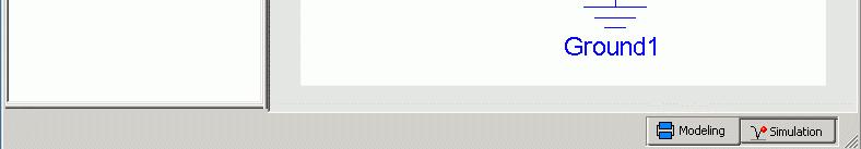
4 Linear Circuit Components II U 0 Voltage sources v a i v b U 0 =v b v a U 0 Current sources Ground v a I 0 I0 u=v v b v a b I 0 = f(t) u V 0 V 0 V 0 = 0 V 0 -
5 Circuit Topology v a i a v a = v b = v c Nodes i a +i b + i c = 0 v c i c i b v b Meshes v a u ab v b u u u ab +u bc + u ca = 0 ca bc v c

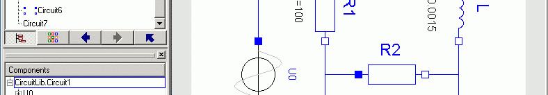
6 An Example I
7 Rules for Systems of Equations I The component and topology equations contain a certain degree of redundancy. For example, it is possible to eliminate all potential variables (v i ) without problems. The current node equation for the ground node is redundant and is not used. The mesh equations are only used if the potential variables are being eliminated. If this is not the case, they are redundant.
8 Rules for Systems of Equations II If the potential variables are eliminated, every circuit component dfi defines two variables: ibl the current (i) through the element and die Voltage (u) across the element. Consequently, we need two equations to compute values for these two variables. One of the equations is the constituent equation of the element itself, the other comes from the topology.
9 An Example II Component equations: i C = C du C/dt u 1 = R 1 i 1 u L = L di L /dt u 2 = R 2 i 2 Node equations: The circuit contains 5 components We require 10 equations in 10 unknowns i 1 = i 2 + i C Mesh equations: U 0 = u 1 + u C u L = u 1 + u 2 u C = u 2
10 Rules for Horizontal Sorting I The time t may be assumed as known. The state variables (variables that appear in differentiated form) may be assumed as known. u 1 =R i 1 1 u 2 = R 2 i 2 i C = C du C /dt u L = L di L /dt i 1 = i 2 +i C U 0 = u 1 + u C u 1 =R i 1 1 u 2 = R 2 i 2 u C = u 2 i C = C du C /dt u L = u 1 + u 2 u L = L di L /dt i 1 = i 2 +i C U 0 = u 1 + u C u C = u 2 u L = u 1 + u 2
11 Rules for Horizontal Sorting II Equations that contain only one unknown must be solved for it. The solved variables are now known. u 1 =R i 1 1 u 2 = R 2 i 2 i C = C du C /dt u L = L di L /dt i 1 = i 2 +i C U 0 = u 1 + u C u 1 =R i 1 1 u 2 = R 2 i 2 u C = u 2 i C = C du C /dt u L = u 1 + u 2 u L = L di L /dt i 1 = i 2 +i C U 0 = u 1 + u C u C = u 2 u L = u 1 + u 2
12 Rules for Horizontal Sorting III Variables that show up in only one equation must be solved for using that equation. u 1 =R i 1 1 u 2 = R 2 i 2 i C = C du C /dt u L = L di L /dt i 1 = i 2 +i C U 0 = u 1 + u C u 1 =R 1 i 1 u 2 = R 2 i 2 u C = u 2 i C = C du C /dt u L = u 1 + u 2 u L = L di L /dt i 1 = i 2 +i C U 0 = u 1 + u C u C = u 2 u L = u 1 + u 2
13 Rules for Horizontal Sorting IV All rules may be used recursively. u 1 =R 1 i 1 u 2 = R 2 i 2 i C = C du C /dt u L = L di L /dt i 1 = i 2 +i C U 0 = u 1 + u C u 1 =R 1 i 1 u 2 = R 2 i 2 u C = u 2 i C = C du C /dt u L = u 1 + u 2 u L = L di L /dt i 1 = i 2 +i C U 0 = u 1 + u C u C = u 2 u L = u 1 + u 2
14 u 1 = R 1 i 1 u 2 = R 2 i 2 i C = C du C /dt u L = L di L /dt i 1 = i 2 + i C U 0 = u 1 + u C u 1 = R 1 i 1 u 2 = R 2 i 2 u C = u 2 u L = u 1 + u 2 i C = C du C /dt u L = L di L /dt i 1 = i 2 + i C U 0 = u 1 + u C u C = u 2 u L = u 1 + u 2 The algorithm is applied, until u 1 = R 1 i 1 i 1 = i 2 + i C every equation defines exactly one variable that is being solved for. u 2 = R 2 2 i 2 U 0 = u 1 + u C i C = C du C /dt u C = u 2 u L = L di L /dt u L = u 1 + u 2 L L L 1 2
15 Rules for Horizontal Sorting V The horizontal sorting can now be performed using symbolic formula manipulation techniques. u 1 =R 1 i 1 u 2 = R 2 i 2 i C = C du C /dt u L = L di L /dt i 1 = i 2 + i C U 0 = u 1 + u C i 1 = u 1 /R 1 i 2 = u 2 /R 2 u C = u 2 du C /dt = i C /C u L = u 1 + u 2 di L /dt = u L /L i C = i 1 - i 2 u 1 = U 0 - u C u 2 = u C u L = u 1 + u 2
16 Rules for Vertical Sorting By now, the equations have become assignment statements. They can be sorted vertically, such that no variable is being used before it has been defined. i 1 = u 1 /R 1 i 2 = u 2 /R 2 du C /dt = i C /C di L /dt = u L /L i C = i 1 - i 2 u 1 = U 0 - u C u 1 = U 0 - u C i 1 = u 1 /R 1 u 2 = u C u L = u 1 + u 2 u 2 = u C i 2 = u 2 /R 2 i C = i 1 - i 2 u L = u 1 + u 2 du C /dt = i C /C C C di L /dt = u L /L
17 Rules for Systems of Equations III Alternatively, it is possible to work with both potentialsand il voltages. In that case, additional equations for the node potentials must be found. These are the potential equations of the components and the potential equations of the topology. Those had been ignored before. The mesh equations are in this case redundant and can beignored.
18 An Example III v 1 Component equations: U 0 = v 1 v 0 v 2 u 1 = R 1 i 1 u 1 = v 1 v 2 u 2 = R 2 i 2 u 2 = v 2 v 0 i C = C du C /dt u C = v 2 v 0 v 0 The circuit contains 5 components and 3nodes nodes. We require 13 equations in 13 unknowns. u L = L di L /dt u L = v 1 v 0 v 0 = 0 Nd Node equations: i 1 = i 2 + i C
19 Sorting The sorting algorithms are applied just like before. The sorting algorithm has already been reduced to a purely mathematical (informational) structure without any remaining knowledge of electrical circuit theory. Therefore, the overall modeling task can be reduced to two sub-problems: 1. Mapping of the physical topology to a system of implicitly formulated DAEs. 2. Conversion of the DAE system into an executable program structure.
20 State-space Representation Linear systems: x n A n n dx dt = A x + B u y = C x + D u Non-linear systems: dx dt = f(x,u,t) y = g(x,u,t) ; x(t 0 ) = x 0 u m y p x = State vector u = Input vector ; x(t 0 ) = x 0 y = Output vector B n m C p n D p m n = Number of state variables m = Number of inputs p = Number of outputs
21 Conversion to State-space Form I du C /dt = i C /C i 2 = u 2 /R 2 = (i 1 - i 2 ) /C u 1 = U 0 - u C i C = i 1 - i 2 i 1 = u 1 /R 1 u L = u 1 + u = i 1 /C - i 2 /C 2 = u 1 /(R 1 C) u 2 /(R 2 C) du C /dt = i C /C = (U 0 - u C ) /(R 1 C) u C /(R 2 C) u 2 = u C di L /dt = u L /L di L /dt = u L /L For each equation defining a state = (u 1 + u 2 ) /L derivative, we substitute the variables on the right-handhand side by = u 1 /L + u 2 /L the equations defining them, until = (U 0 - u C ) /L + u C /L the state derivatives depend only on state variables and inputs. = U 0 /L
22 We let: Conversion to State-space Form II x 1 = u C x 2 = i L u = U 0 y = u C x 1 = - 1 x 2 = u L [ ] x 1 R 1 C R 2 C R 1 C u y = x 1


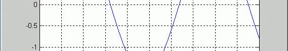
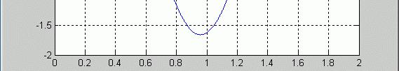
23 An Example IV
24 References Cellier, F.E. (1991), Continuous System Modeling, dl Springer-Verlag, New York, Chapter 3. Cellier, F.E. (2001), Matlab code of circuit example.
Electrical Circuits I
 Electrical Circuits I This lecture discusses the mathematical modeling of simple electrical linear circuits. When modeling a circuit, one ends up with a set of implicitly formulated algebraic and differential
1D Mechanical Systems
 1D Mechanical Systems In this lecture, we shall deal with 1D mechanical systems that can either ih translate or rotate in a one-dimensional i space. We shall demonstrate the similarities betweeneen the
COOKBOOK KVL AND KCL A COMPLETE GUIDE
 1250 COOKBOOK KVL AND KCL A COMPLETE GUIDE Example circuit: 1) Label all source and component values with a voltage drop measurement (+,- ) and a current flow measurement (arrow): By the passive sign convention,
1. Review of Circuit Theory Concepts
 1. Review of Circuit Theory Concepts Lecture notes: Section 1 ECE 65, Winter 2013, F. Najmabadi Circuit Theory is an pproximation to Maxwell s Electromagnetic Equations circuit is made of a bunch of elements
System Modeling. Lecture-2. Emam Fathy Department of Electrical and Control Engineering
 System Modeling Lecture-2 Emam Fathy Department of Electrical and Control Engineering email: emfmz@yahoo.com 1 Types of Systems Static System: If a system does not change with time, it is called a static
Dynamic Modeling. For the mechanical translational system shown in Figure 1, determine a set of first order
 QUESTION 1 For the mechanical translational system shown in, determine a set of first order differential equations describing the system dynamics. Identify the state variables and inputs. y(t) x(t) k m
EE292: Fundamentals of ECE
 EE292: Fundamentals of ECE Fall 2012 TTh 10:00-11:15 SEB 1242 Lecture 14 121011 http://www.ee.unlv.edu/~b1morris/ee292/ 2 Outline Review Steady-State Analysis RC Circuits RL Circuits 3 DC Steady-State
Introduction to Controls
 EE 474 Review Exam 1 Name Answer each of the questions. Show your work. Note were essay-type answers are requested. Answer with complete sentences. Incomplete sentences will count heavily against the grade.
Problem info Geometry model Labelled Objects Results Nonlinear dependencies
 Problem info Problem type: Transient Magnetics (integration time: 9.99999993922529E-09 s.) Geometry model class: Plane-Parallel Problem database file names: Problem: circuit.pbm Geometry: Circuit.mod Material
Kirchhoff's Laws and Circuit Analysis (EC 2)
") Kirchhoff's Laws and Circuit Analysis (EC ) Circuit analysis: solving for I and V at each element Linear circuits: involve resistors, capacitors, inductors Initial analysis uses only resistors Power sources,
Kirchhoff's Laws and Circuit Analysis (EC ) Circuit analysis: solving for I and V at each element Linear circuits: involve resistors, capacitors, inductors Initial analysis uses only resistors Power sources,
Lecture #3. Review: Power
 Lecture #3 OUTLINE Power calculations Circuit elements Voltage and current sources Electrical resistance (Ohm s law) Kirchhoff s laws Reading Chapter 2 Lecture 3, Slide 1 Review: Power If an element is
7 Differential Algebraic Equations
 7 Differential Algebraic Equations Preview In this chapter, we shall analyze simulation problems that don t present themselves initially in an explicit state space form. For many physical systems, it is
Chapter 10: Sinusoidal Steady-State Analysis
 Chapter 10: Sinusoidal Steady-State Analysis 10.1 10.2 10.3 10.4 10.5 10.6 10.9 Basic Approach Nodal Analysis Mesh Analysis Superposition Theorem Source Transformation Thevenin & Norton Equivalent Circuits
Sinusoidal Steady State Analysis (AC Analysis) Part I
 Part I") Sinusoidal Steady State Analysis (AC Analysis) Part I Amin Electronics and Electrical Communications Engineering Department (EECE) Cairo University elc.n102.eng@gmail.com http://scholar.cu.edu.eg/refky/
Sinusoidal Steady State Analysis (AC Analysis) Part I Amin Electronics and Electrical Communications Engineering Department (EECE) Cairo University elc.n102.eng@gmail.com http://scholar.cu.edu.eg/refky/
9. Introduction and Chapter Objectives
 Real Analog - Circuits 1 Chapter 9: Introduction to State Variable Models 9. Introduction and Chapter Objectives In our analysis approach of dynamic systems so far, we have defined variables which describe
Exploring Operations Involving Complex Numbers. (3 + 4x) (2 x) = 6 + ( 3x) + +
 (2 x) = 6 + ( 3x) + +") Name Class Date 11.2 Complex Numbers Essential Question: What is a complex number, and how can you add, subtract, and multiply complex numbers? Explore Exploring Operations Involving Complex Numbers In
Name Class Date 11.2 Complex Numbers Essential Question: What is a complex number, and how can you add, subtract, and multiply complex numbers? Explore Exploring Operations Involving Complex Numbers In
Outline. Week 5: Circuits. Course Notes: 3.5. Goals: Use linear algebra to determine voltage drops and branch currents.
 Outline Week 5: Circuits Course Notes: 3.5 Goals: Use linear algebra to determine voltage drops and branch currents. Components in Resistor Networks voltage source current source resistor Components in
2005 AP PHYSICS C: ELECTRICITY AND MAGNETISM FREE-RESPONSE QUESTIONS
 2005 AP PHYSICS C: ELECTRICITY AND MAGNETISM In the circuit shown above, resistors 1 and 2 of resistance R 1 and R 2, respectively, and an inductor of inductance L are connected to a battery of emf e and
AC Circuits Homework Set
 Problem 1. In an oscillating LC circuit in which C=4.0 μf, the maximum potential difference across the capacitor during the oscillations is 1.50 V and the maximum current through the inductor is 50.0 ma.
ELECTRONICS E # 1 FUNDAMENTALS 2/2/2011
 FE Review 1 ELECTRONICS E # 1 FUNDAMENTALS Electric Charge 2 In an electric circuit it there is a conservation of charge. The net electric charge is constant. There are positive and negative charges. Like
Consider the following generalized simple circuit
 ntroduction to Circuit Analysis Getting Started We analyze circuits for several reasons Understand how they work Learn how to design from other people s work Debug our own designs Troubleshoot circuit
Linear System Theory
 Linear System Theory - Laplace Transform Prof. Robert X. Gao Department of Mechanical Engineering University of Connecticut Storrs, CT 06269 Outline What we ve learned so far: Setting up Modeling Equations
Chapter 10 AC Analysis Using Phasors
 Chapter 10 AC Analysis Using Phasors 10.1 Introduction We would like to use our linear circuit theorems (Nodal analysis, Mesh analysis, Thevenin and Norton equivalent circuits, Superposition, etc.) to
ET3-7: Modelling II(V) Electrical, Mechanical and Thermal Systems
 Electrical, Mechanical and Thermal Systems") ET3-7: Modelling II(V) Electrical, Mechanical and Thermal Systems Agenda of the Day 1. Resume of lesson I 2. Basic system models. 3. Models of basic electrical system elements 4. Application of Matlab/Simulink
ET3-7: Modelling II(V) Electrical, Mechanical and Thermal Systems Agenda of the Day 1. Resume of lesson I 2. Basic system models. 3. Models of basic electrical system elements 4. Application of Matlab/Simulink
Inductors. Hydraulic analogy Duality with capacitor Charging and discharging. Lecture 12: Inductors
 Lecture 12: nductors nductors Hydraulic analogy Duality with capacitor Charging and discharging Robert R. McLeod, University of Colorado http://hilaroad.com/camp/projects/magnet.html 99 Lecture 12: nductors
Automatic Formulation of Circuit Equations
 ECE 570 Session 3 IC 752-E Computer Aided Engineering for Integrated Circuits Automatic Formulation of Circuit Equations Objective: Basics of computer aided analysis/simulation Outline:. Discussion of
 Network Topology-2 & Dual and Duality Choice of independent branch currents and voltages: The solution of a network involves solving of all branch currents and voltages. We know that the branch current
Engineering Fundamentals and Problem Solving, 6e
 Engineering Fundamentals and Problem Solving, 6e Chapter 17 Electrical Circuits Chapter Objectives Compute the equivalent resistance of resistors in series and in parallel Apply Ohm s law to a resistive
Figure Circuit for Question 1. Figure Circuit for Question 2
 Exercises 10.7 Exercises Multiple Choice 1. For the circuit of Figure 10.44 the time constant is A. 0.5 ms 71.43 µs 2, 000 s D. 0.2 ms 4 Ω 2 Ω 12 Ω 1 mh 12u 0 () t V Figure 10.44. Circuit for Question
EE 16B Midterm 2, March 21, Name: SID #: Discussion Section and TA: Lab Section and TA: Name of left neighbor: Name of right neighbor:
 EE 16B Midterm 2, March 21, 2017 Name: SID #: Discussion Section and TA: Lab Section and TA: Name of left neighbor: Name of right neighbor: Important Instructions: Show your work. An answer without explanation
Revision: June 11, E Main Suite D Pullman, WA (509) Voice and Fax
 Voice and Fax") .5.1: Second Order ircuits Revision: June 11, 010 15 E Main Suite D Pullman, WA 99163 (509) 334 6306 Voice and Fax Overview Second order systems are, by definition, systems whose input-output relationship
.5.1: Second Order ircuits Revision: June 11, 010 15 E Main Suite D Pullman, WA 99163 (509) 334 6306 Voice and Fax Overview Second order systems are, by definition, systems whose input-output relationship
Physics for Scientists & Engineers 2
 Electromagnetic Oscillations Physics for Scientists & Engineers Spring Semester 005 Lecture 8! We have been working with circuits that have a constant current a current that increases to a constant current
To find the step response of an RC circuit
 To find the step response of an RC circuit v( t) v( ) [ v( t) v( )] e tt The time constant = RC The final capacitor voltage v() The initial capacitor voltage v(t ) To find the step response of an RL circuit
Generalized Analysis for ZCS
 Generalized Analysis for ZCS The QRC cells (ZCS and ZS) analysis, including the switching waveforms, can be generalized, and then applies to each converter. nstead of analyzing each QRC cell (L-type ZCS,
Chapter 3. Steady-State Equivalent Circuit Modeling, Losses, and Efficiency
 Chapter 3. Steady-State Equivalent Circuit Modeling, Losses, and Efficiency 3.1. The dc transformer model 3.2. Inclusion of inductor copper loss 3.3. Construction of equivalent circuit model 3.4. How to
7.3 State Space Averaging!
 7.3 State Space Averaging! A formal method for deriving the small-signal ac equations of a switching converter! Equivalent to the modeling method of the previous sections! Uses the state-space matrix description
FE Review 2/2/2011. Electric Charge. Electric Energy ELECTRONICS # 1 FUNDAMENTALS
 FE eview ELECONICS # FUNDAMENALS Electric Charge 2 In an electric circuit there is a conservation of charge. he net electric charge is constant. here are positive and negative charges. Like charges repel
ECE2262 Electric Circuits. Chapter 1: Basic Concepts. Overview of the material discussed in ENG 1450
 ECE2262 Electric Circuits Chapter 1: Basic Concepts Overview of the material discussed in ENG 1450 1 Circuit Analysis 2 Lab -ECE 2262 3 LN - ECE 2262 Basic Quantities: Current, Voltage, Energy, Power The
In this lecture, we will consider how to analyse an electrical circuit by applying KVL and KCL. As a result, we can predict the voltages and currents
 In this lecture, we will consider how to analyse an electrical circuit by applying KVL and KCL. As a result, we can predict the voltages and currents around an electrical circuit. This is a short lecture,
Solution to Homework 2
 Solution to Homework. Substitution and Nonexact Differential Equation Made Exact) [0] Solve dy dx = ey + 3e x+y, y0) = 0. Let u := e x, v = e y, and hence dy = v + 3uv) dx, du = u)dx, dv = v)dy = u)dv
Electric Circuit Theory
 Electric Circuit Theory Nam Ki Min nkmin@korea.ac.kr 010-9419-2320 Chapter 18 Two-Port Circuits Nam Ki Min nkmin@korea.ac.kr 010-9419-2320 Contents and Objectives 3 Chapter Contents 18.1 The Terminal Equations
BFF1303: ELECTRICAL / ELECTRONICS ENGINEERING. Alternating Current Circuits : Basic Law
 BFF1303: ELECTRICAL / ELECTRONICS ENGINEERING Alternating Current Circuits : Basic Law Ismail Mohd Khairuddin, Zulkifil Md Yusof Faculty of Manufacturing Engineering Universiti Malaysia Pahang Alternating
Phasors: Impedance and Circuit Anlysis. Phasors
 Phasors: Impedance and Circuit Anlysis Lecture 6, 0/07/05 OUTLINE Phasor ReCap Capacitor/Inductor Example Arithmetic with Complex Numbers Complex Impedance Circuit Analysis with Complex Impedance Phasor
A tricky node-voltage situation
 A tricky node-voltage situation The node-method will always work you can always generate enough equations to determine all of the node voltages. The prescribed method quite well, but there is one situation
EE/ME/AE324: Dynamical Systems. Chapter 7: Transform Solutions of Linear Models
 EE/ME/AE324: Dynamical Systems Chapter 7: Transform Solutions of Linear Models The Laplace Transform Converts systems or signals from the real time domain, e.g., functions of the real variable t, to the
DC STEADY STATE CIRCUIT ANALYSIS
 DC STEADY STATE CIRCUIT ANALYSIS 1. Introduction The basic quantities in electric circuits are current, voltage and resistance. They are related with Ohm s law. For a passive branch the current is: I=
Chapter 10 Sinusoidal Steady State Analysis Chapter Objectives:
 Chapter 10 Sinusoidal Steady State Analysis Chapter Objectives: Apply previously learn circuit techniques to sinusoidal steady-state analysis. Learn how to apply nodal and mesh analysis in the frequency
Review: control, feedback, etc. Today s topic: state-space models of systems; linearization
 Plan of the Lecture Review: control, feedback, etc Today s topic: state-space models of systems; linearization Goal: a general framework that encompasses all examples of interest Once we have mastered
Chapter 2. Engr228 Circuit Analysis. Dr Curtis Nelson
 Chapter 2 Engr228 Circuit Analysis Dr Curtis Nelson Chapter 2 Objectives Understand symbols and behavior of the following circuit elements: Independent voltage and current sources; Dependent voltage and
AC Circuit Analysis and Measurement Lab Assignment 8
 Electric Circuit Lab Assignments elcirc_lab87.fm - 1 AC Circuit Analysis and Measurement Lab Assignment 8 Introduction When analyzing an electric circuit that contains reactive components, inductors and
Project 4: Introduction to Circuits The attached Project was prepared by Professor Yih-Fang Huang from the department of Electrical Engineering.
 Project 4: Introduction to Circuits The attached Project was prepared by Professor Yih-Fang Huang from the department of Electrical Engineering. The examples given are example of basic problems that you
Circuit Analysis-II. Circuit Analysis-II Lecture # 5 Monday 23 rd April, 18
 Circuit Analysis-II Capacitors in AC Circuits Introduction ü The instantaneous capacitor current is equal to the capacitance times the instantaneous rate of change of the voltage across the capacitor.
REUNotes08-CircuitBasics May 28, 2008
 Chapter One Circuits (... introduction here... ) 1.1 CIRCUIT BASICS Objects may possess a property known as electric charge. By convention, an electron has one negative charge ( 1) and a proton has one
2.004 Dynamics and Control II Spring 2008
 MIT OpenCourseWare http://ocwmitedu 00 Dynamics and Control II Spring 00 For information about citing these materials or our Terms of Use, visit: http://ocwmitedu/terms Massachusetts Institute of Technology
Transient Analysis of Electrical Circuits Using Runge- Kutta Method and its Application
 International Journal of Scientific and Research Publications, Volume 3, Issue 11, November 2013 1 Transient Analysis of Electrical Circuits Using Runge- Kutta Method and its Application Anuj Suhag School
QUIZ 1 SOLUTION. One way of labeling voltages and currents is shown below.
 F 14 1250 QUIZ 1 SOLUTION EX: Find the numerical value of v 2 in the circuit below. Show all work. SOL'N: One method of solution is to use Kirchhoff's and Ohm's laws. The first step in this approach is
ECE2262 Electric Circuit
 ECE2262 Electric Circuit Chapter 7: FIRST AND SECOND-ORDER RL AND RC CIRCUITS Response to First-Order RL and RC Circuits Response to Second-Order RL and RC Circuits 1 2 7.1. Introduction 3 4 In dc steady
Capacitor Action. 3. Capacitor Action Theory Support. Electronics - AC Circuits
 Capacitor Action Topics covered in this presentation: Capacitors on DC Capacitors on AC Capacitor Charging Capacitor Discharging 1 of 18 Charging a Capacitor (DC) Before looking at how capacitors charge
CURRENT SOURCES EXAMPLE 1 Find the source voltage Vs and the current I1 for the circuit shown below SOURCE CONVERSIONS
 CURRENT SOURCES EXAMPLE 1 Find the source voltage Vs and the current I1 for the circuit shown below EXAMPLE 2 Find the source voltage Vs and the current I1 for the circuit shown below SOURCE CONVERSIONS
ENGR 2405 Class No Electric Circuits I
 ENGR 2405 Class No. 48056 Electric Circuits I Dr. R. Williams Ph.D. rube.williams@hccs.edu Electric Circuit An electric circuit is an interconnec9on of electrical elements Charge Charge is an electrical
The Process. 218 Technical Applications of Computers
 ble. Right now, we will introduce simulink on transfer functions with the simple transfer function for the differential equation, dx(t)/dt + x(t) = u(t). Our input signal of u(t) will be the step funtion.
Applications of Second-Order Differential Equations
 Applications of Second-Order Differential Equations ymy/013 Building Intuition Even though there are an infinite number of differential equations, they all share common characteristics that allow intuition
Lecture # 2 Basic Circuit Laws
 CPEN 206 Linear Circuits Lecture # 2 Basic Circuit Laws Dr. Godfrey A. Mills Email: gmills@ug.edu.gh Phone: 026907363 February 5, 206 Course TA David S. Tamakloe CPEN 206 Lecture 2 205_206 What is Electrical
C R. Consider from point of view of energy! Consider the RC and LC series circuits shown:
 ircuits onsider the R and series circuits shown: ++++ ---- R ++++ ---- Suppose that the circuits are formed at t with the capacitor charged to value. There is a qualitative difference in the time development
Basic Electronics. Introductory Lecture Course for. Technology and Instrumentation in Particle Physics Chicago, Illinois June 9-14, 2011
 Basic Electronics Introductory Lecture Course for Technology and Instrumentation in Particle Physics 2011 Chicago, Illinois June 9-14, 2011 Presented By Gary Drake Argonne National Laboratory drake@anl.gov
8. Introduction and Chapter Objectives
 Real Analog - Circuits Chapter 8: Second Order Circuits 8. Introduction and Chapter Objectives Second order systems are, by definition, systems whose input-output relationship is a second order differential
Lecture 2 and 3: Controllability of DT-LTI systems
 1 Lecture 2 and 3: Controllability of DT-LTI systems Spring 2013 - EE 194, Advanced Control (Prof Khan) January 23 (Wed) and 28 (Mon), 2013 I LTI SYSTEMS Recall that continuous-time LTI systems can be
(Refer Slide Time: 00:01:30 min)
") Control Engineering Prof. M. Gopal Department of Electrical Engineering Indian Institute of Technology, Delhi Lecture - 3 Introduction to Control Problem (Contd.) Well friends, I have been giving you various
Control Engineering Prof. M. Gopal Department of Electrical Engineering Indian Institute of Technology, Delhi Lecture - 3 Introduction to Control Problem (Contd.) Well friends, I have been giving you various
EIE/ENE 104 Electric Circuit Theory
 EIE/ENE 104 Electric Circuit Theory Lecture 01a: Circuit Analysis and Electrical Engineering Week #1 : Dejwoot KHAWPARISUTH office: CB40906 Tel: 02-470-9065 Email: dejwoot.kha@kmutt.ac.th http://webstaff.kmutt.ac.th/~dejwoot.kha/
Electric Circuits I FINAL EXAMINATION
 EECS:300, Electric Circuits I s6fs_elci7.fm - Electric Circuits I FINAL EXAMINATION Problems Points.. 3. 0 Total 34 Was the exam fair? yes no 5//6 EECS:300, Electric Circuits I s6fs_elci7.fm - Problem
Basic RL and RC Circuits R-L TRANSIENTS: STORAGE CYCLE. Engineering Collage Electrical Engineering Dep. Dr. Ibrahim Aljubouri
 st Class Basic RL and RC Circuits The RL circuit with D.C (steady state) The inductor is short time at Calculate the inductor current for circuits shown below. I L E R A I L E R R 3 R R 3 I L I L R 3 R
CIRCUITS AND ELECTRONICS. Introduction and Lumped Circuit Abstraction
 6.002 CIRCUITS AND ELECTRONICS Introduction and Lumped Circuit Abstraction ADMINISTRIVIA Lecturer: Prof. Anant Agarwal Textbook: Agarwal and Lang (A&L) Readings are important! Handout no. 3 Web site http://web.mit.edu/6.002/www/fall00
Computing Phase Noise Eigenfunctions Directly from Steady-State Jacobian Matrices
 Computing Phase Noise Eigenfunctions Directly from Steady-State Jacobian Matrices Alper Demir David Long Jaijeet Roychowdhury Bell Laboratories Murray Hill New Jersey USA Abstract The main effort in oscillator
Besides resistors, capacitors are one of the most common electronic components that you will encounter. Sometimes capacitors are components that one
 1 Besides resistors, capacitors are one of the most common electronic components that you will encounter. Sometimes capacitors are components that one would deliberately add to a circuit. Other times,
Electric Circuits II Sinusoidal Steady State Analysis. Dr. Firas Obeidat
 Electric Circuits II Sinusoidal Steady State Analysis Dr. Firas Obeidat 1 Table of Contents 1 2 3 4 5 Nodal Analysis Mesh Analysis Superposition Theorem Source Transformation Thevenin and Norton Equivalent
Inductance, RL Circuits, LC Circuits, RLC Circuits
 Inductance, R Circuits, C Circuits, RC Circuits Inductance What happens when we close the switch? The current flows What does the current look like as a function of time? Does it look like this? I t Inductance
Lecture 6: Impedance (frequency dependent. resistance in the s- world), Admittance (frequency. dependent conductance in the s- world), and
, Admittance (frequency. dependent conductance in the s- world), and") Lecture 6: Impedance (frequency dependent resistance in the s- world), Admittance (frequency dependent conductance in the s- world), and Consequences Thereof. Professor Ray, what s an impedance? Answers:
Lecture 6: Impedance (frequency dependent resistance in the s- world), Admittance (frequency dependent conductance in the s- world), and Consequences Thereof. Professor Ray, what s an impedance? Answers:
Physics 116A Notes Fall 2004
 Physics 116A Notes Fall 2004 David E. Pellett Draft v.0.9 Notes Copyright 2004 David E. Pellett unless stated otherwise. References: Text for course: Fundamentals of Electrical Engineering, second edition,
ECE 201 Fall 2009 Final Exam
 ECE 01 Fall 009 Final Exam December 16, 009 Division 0101: Tan (11:30am) Division 001: Clark (7:30 am) Division 0301: Elliott (1:30 pm) Instructions 1. DO NOT START UNTIL TOLD TO DO SO.. Write your Name,
Lecture 4: R-L-C Circuits and Resonant Circuits
 Lecture 4: R-L-C Circuits and Resonant Circuits RLC series circuit: What's V R? Simplest way to solve for V is to use voltage divider equation in complex notation: V X L X C V R = in R R + X C + X L L
THERE are numerous number of products powered by
 Symbolic Computer-Aided Design for Wireless Power Transmission Takuya Hirata, Univ. Miyazaki, Kazuya Yamaguchi, Univ. Miyazaki, Yuta Yamamoto, Univ. Miyazaki and Ichijo Hodaka, Univ. Miyazaki Abstract
EE 3120 Electric Energy Systems Study Guide for Prerequisite Test Wednesday, Jan 18, pm, Room TBA
 EE 3120 Electric Energy Systems Study Guide for Prerequisite Test Wednesday, Jan 18, 2006 6-7 pm, Room TBA First retrieve your EE2110 final and other course papers and notes! The test will be closed book
CIRCUIT ANALYSIS TECHNIQUES
 APPENDI B CIRCUIT ANALSIS TECHNIQUES The following methods can be used to combine impedances to simplify the topology of an electric circuit. Also, formulae are given for voltage and current division across/through
Modeling of Electrical Elements
 Modeling of Electrical Elements Dr. Bishakh Bhattacharya Professor, Department of Mechanical Engineering IIT Kanpur Joint Initiative of IITs and IISc - Funded by MHRD This Lecture Contains Modeling of
ENGR 2405 Chapter 8. Second Order Circuits
 ENGR 2405 Chapter 8 Second Order Circuits Overview The previous chapter introduced the concept of first order circuits. This chapter will expand on that with second order circuits: those that need a second
Transient response of RC and RL circuits ENGR 40M lecture notes July 26, 2017 Chuan-Zheng Lee, Stanford University
 Transient response of C and L circuits ENG 40M lecture notes July 26, 2017 Chuan-Zheng Lee, Stanford University esistor capacitor (C) and resistor inductor (L) circuits are the two types of first-order
48520 Electronics & Circuits: Web Tutor
 852 Electronics & Circuits: Web Tutor Topic : Resistive Circuits 2 Help for Exercise.: Nodal Analysis, circuits with I, R and controlled sources. The purpose of this exercise is to further extend Nodal
PROBLEMS FOR EXPERIMENT ES: ESTIMATING A SECOND Solutions
 Massachusetts Institute of Technology Physics Department 801X Fall 2002 PROBLEMS FOR EXPERIMENT ES: ESTIMATING A SECOND Solutions Problem 1: Use your calculator or your favorite software program to compute
Review of Circuit Analysis
 Review of Circuit Analysis Fundamental elements Wire Resistor Voltage Source Current Source Kirchhoff s Voltage and Current Laws Resistors in Series Voltage Division EE 42 Lecture 2 1 Voltage and Current
Designing Information Devices and Systems I Fall 2017 Official Lecture Notes Note 13
 EECS 16A Designing Information Devices and Systems I Fall 2017 Official Lecture Notes Note 13 13.1 Analysis Review: Voltage Divider In order to review the analysis procedure described in the previous note,
Mod. Sim. Dyn. Sys. Amplifiers page 1
 AMPLIFIERS A circuit containing only capacitors, amplifiers (transistors) and resistors may resonate. A circuit containing only capacitors and resistors may not. Why does amplification permit resonance
EE40 Midterm Review Prof. Nathan Cheung
 EE40 Midterm Review Prof. Nathan Cheung 10/29/2009 Slide 1 I feel I know the topics but I cannot solve the problems Now what? Slide 2 R L C Properties Slide 3 Ideal Voltage Source *Current depends d on
School of Engineering Faculty of Built Environment, Engineering, Technology & Design
 Module Name and Code : ENG60803 Real Time Instrumentation Semester and Year : Semester 5/6, Year 3 Lecture Number/ Week : Lecture 3, Week 3 Learning Outcome (s) : LO5 Module Co-ordinator/Tutor : Dr. Phang
Writing Circuit Equations
 2 C H A P T E R Writing Circuit Equations Objectives By the end of this chapter, you should be able to do the following: 1. Find the complete solution of a circuit using the exhaustive, node, and mesh
Electrical Circuits (2)
") Electrical Circuits (2) Lecture 7 Transient Analysis Dr.Eng. Basem ElHalawany Extra Reference for this Lecture Chapter 16 Schaum's Outline Of Theory And Problems Of Electric Circuits https://archive.org/details/theoryandproblemsofelectriccircuits
Electrical Circuits (2) Lecture 7 Transient Analysis Dr.Eng. Basem ElHalawany Extra Reference for this Lecture Chapter 16 Schaum's Outline Of Theory And Problems Of Electric Circuits https://archive.org/details/theoryandproblemsofelectriccircuits
A tricky node-voltage situation
 A tricky node-voltage situation The node-method will always work you can always generate enough equations to determine all of the node voltages. The method we have outlined well in almost all cases, but
Lecture 7: Laplace Transform and Its Applications Dr.-Ing. Sudchai Boonto
 Dr-Ing Sudchai Boonto Department of Control System and Instrumentation Engineering King Mongkut s Unniversity of Technology Thonburi Thailand Outline Motivation The Laplace Transform The Laplace Transform
R. W. Erickson. Department of Electrical, Computer, and Energy Engineering University of Colorado, Boulder
 . W. Erickson Department of Electrical, Computer, and Energy Engineering University of Colorado, Boulder 2.4 Cuk converter example L 1 C 1 L 2 Cuk converter, with ideal switch i 1 i v 1 2 1 2 C 2 v 2 Cuk
LECTURE 8 RC AND RL FIRST-ORDER CIRCUITS (PART 1)
") CIRCUITS by Ulaby & Maharbiz LECTURE 8 RC AND RL FIRST-ORDER CIRCUITS (PART 1) 07/18/2013 ECE225 CIRCUIT ANALYSIS All rights reserved. Do not copy or distribute. 2013 National Technology and Science Press
CIRCUITS by Ulaby & Maharbiz LECTURE 8 RC AND RL FIRST-ORDER CIRCUITS (PART 1) 07/18/2013 ECE225 CIRCUIT ANALYSIS All rights reserved. Do not copy or distribute. 2013 National Technology and Science Press
Lecture 35: FRI 17 APR Electrical Oscillations, LC Circuits, Alternating Current I
 Physics 3 Jonathan Dowling Lecture 35: FRI 7 APR Electrical Oscillations, LC Circuits, Alternating Current I Nikolai Tesla What are we going to learn? A road map Electric charge è Electric force on other