Undulator Line Developments Update. Efim Gluskin APS/ANL LCLS TAC Meeting, SLAC, Stanford December 10-11, 2001
|
|
|
- Rhoda Quinn
- 5 years ago
- Views:
Transcription
1 Undulator Line Developments Update Efim Gluskin APS/ANL LCLS TAC Meeting, SLAC, Stanford December 10-11, 2001
2 Undulator Prototype Magnetic characterization of magnets Mechanical certification of poles Design, construction and testing of undulator movers Assembly of magnetic structure Quadrupole Lens Prototype Mechanical and magnetic charaterization Conceptual design of the retractable lens
3 Electron Beam Diagnostics Design of the button-type BPM Conceptual design of the electronics X-ray Beam Diagnostics Conceptual design of the mechanical assembly Universal diagnostics for high- and low-energy
4
5
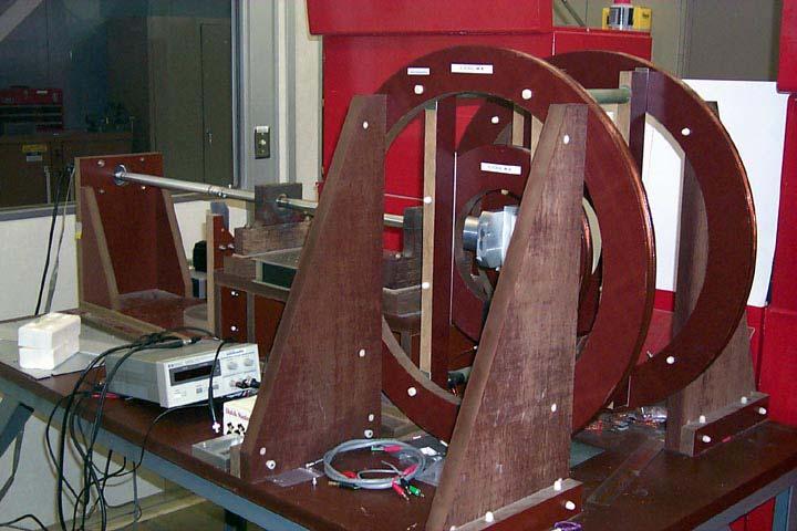
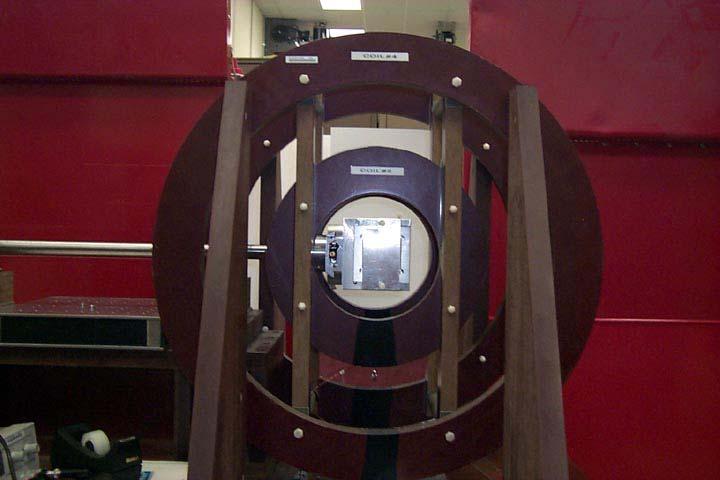
6 Helmholtz coils measure all three components of the total moment of the magnet block. Helmholtz coil measurements were made by vendor and delivered with the magnets. Comparison measurements made at APS agree so closely with vendor s measurements that repeating all the measurements is unnecessary.
7 Requirements for the magnet blocks were: All the same strength within ±1% Angle of magnetization parallel to geometric axis within ±2 These requirements were exceeded.
8 100 Number of Magnets Br (T) Distribution of total magnetic moments in the population of magnet blocks. Note that all the magnets fall within a variation of ±0.5%.
9 Number Number My (T) Distribution of vertical magnetic moments in the overall magnet population. All the magnets have some vertical moment - the range is from 0.7 to 1.3, with an average of 1.0. The magnets are symmetric so that the vertical moment can be oriented in either direction during assembly. The blocks have no horizontal transverse moment.
10 Sorting considerations: -> Main component of the total moment of the block First integral of the field through a half-period test fixture
11 Magnet Moment (T) Magnet Number Total magnetic moment of the magnet blocks for the LCLS prototype, ordered by magnet serial number.
12 Total Magnet Moment (T) Magnet block strength, with the magnets in order of increasing magnetic moment.
13 (M n + M N-n )/ After pairing the magnets by matching strong to weak, to even out the distribution.
14 Population Sorted_Pop Population M total [T] Histogram showing frequency vs. total magnetic moment. The pink squares show the result after pairing the magnets.
15 Sorting considerations: Main component of the total moment of the block ->First integral of the field through a half-period test fixture

16
17 First Vertical Field Integral (G-cm) J1p Aver=27.1 Jin Aver= Magnet First field integral through the half-period test fixture. Red triangles are for magnets with a positive vertical component of the top magnet s total moment (i.e., same as bottom magnet); circles are for a negative vertical component (i.e., opposite moments for top and bottom magnets). The vertical component of the moment makes a clear difference, though there are some oddball magnets.
18 Sorting considerations: Main component of the total moment of the block First integral of the field through a half-period test fixture -> Distribution of moment within the magnet block
19 80 First field Integral(G-cm) J1p J1n Magnet First field integral through the half-period test fixture when the same magnet is oriented with its vertical moment positive (blue +) and negative (red -), for a few of the magnets. The positive orientation usually gives a higher integral, but not always.
20 10x Hall Probe Calculations Z(mm) Difference in vertical on-axis field when magnet block is rotated to change the vertical component its field, plotted vs. z. The measured effect may differ from the calculation if the distribution of the vertical magnetization in the magnet block is not uniform; this can affect the phase errors.
21 Negative Phase (AU) Positive Magnet Measurements of phase for LCLS prototype magnets. Red circles and blue x s are for negative and positive orientations of the vertical moment component. The RMS variation among the negative points is 0.6, and 0.4 among the positive.
22 Other factors that affect the half-period measurements have been attributed to: which pole the magnet is up against non-parallel sides of the magnet block For the initial assembly of the first section of the undulator, not all these will be taken into consideration in the magnet arrangement. Instead, the pairs of top and bottom magnets will be selected by matching strongest total moment to weakest. The top magnet position will alternate between the stronger and the weaker of the magnet pair. Rotations will be as the magnets were originally measured, i.e., random. The result will be compared to the half-period test measurements. The effect of rotations will be compared to measurements, too, to determine whether all magnets need to be measured in both rotations, and we will go from there.
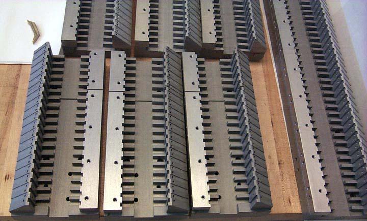
23 The Poles All the poles have been manufactured and assembled to their titanium ears. Most have completed the magnetic anneal. A few poles cracked during the anneal, at the location of the pins. Replacements have been manufactured and await annealing. Dimensional checking found that the poles are very uniform: the same height to ~10 µm, and thicknesses are good.

24
25
26 There are two small problems with the poles, however: Pole chamfer is 1 mm instead of the 0.5 mm chosen from the magnetic modeling. This should reduce the undulator effective field by ~1.7% (no change in the peak field), equivalent to a gap change of ~0.16 mm. This is a small problem. There are flaws in some poles, due, we believe, to the EDM wire breaking when the pole blanks were sliced off the vanadium permendur bar.
, and the deepest are ~0.")
27 Lines on pole face may be 1 or 2 mm wide (where several are close together), and the deepest are ~0.2 mm.
28 Magnetic Field(T) Bad spot X(mm) Magnetic field vs. x, with a bad pole. Solid line corresponds to field between two good poles, dashed line corresponds to field between a good and a bad pole. Sign of the field is reversed. Location of scratches is indicated. Overall slope is due to a slight cant in the pole mounting.

29

30
31
32 1 L L 2 Phase Tuning L 2 cos k 1+ K 2 /2 z dz = 2γ 2 Where, k 0 = 2k u γ 2 /1+ K 2 /2 is the synchronous wave vector k 0 + k k u γ K N ( ) detuned wave vector undulator wave vector relativistic fac tor sin k πn k 0 k πn k 0 undulator deflection pa rameter number of p eriods of the undulator section The specified maximum of the allowed energy gain reduction is 2%. It results k k 0 <.14% Temperature variation compensation : up to +1.5ºc
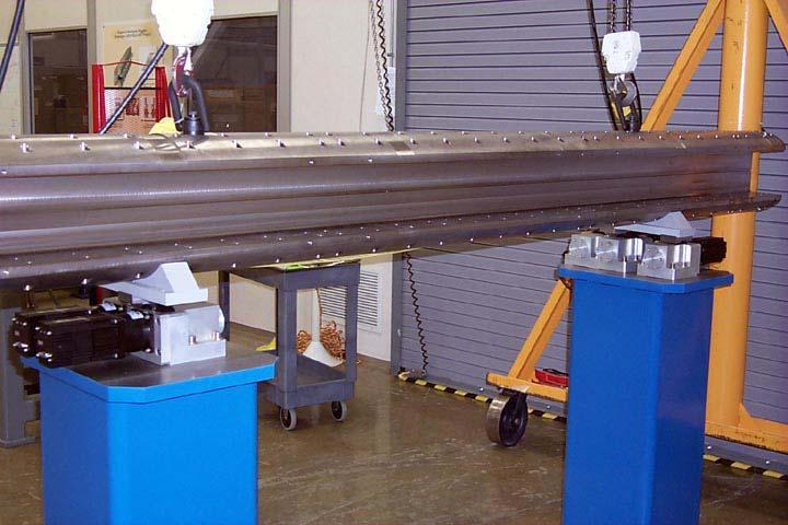
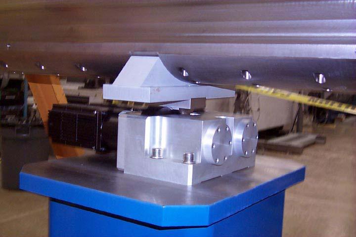
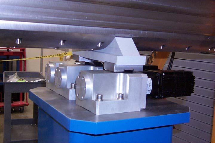
33 Tests of the eccentric cam positioning system for the undulators
34
35
36
37 Alignment of the LCLS undulators: No alignment in longitudinal direction Each undulator is supported by three alignment stages: first and second alignment stages move undulator in two transverse directions, third stage moves in vertical direction only. Alignment range is 6mm, resolution is: 3mm * 2π / 4000 / 100 = 47 nm Coordinate relations: X = (A - B) / 2 Y = (A + B) / 2 B Y A X

38 Testing software: EPICS based Program features: adjustment in horizontal (X) and vertical (Y) directions: -upstream end only - downstream end only - upstream stage only - downstream stages only - parallel shift of the device - rotation of the device around X and Y axes. individual tweaking of each motor Readback channels: Five incremental rotary encoders integrated in servomotors - resolution 4000 counts / turn Testing of the stages is done by Heidenhain MT25 incremental linear encoders -measuring range 25 mm - accuracy ± 0.5 µm - resolution 40nm
39 Positioning error during vertical adjustment
40 Positioning error during horizontal adjustment
41 Discussion and future developments: Positioning reproducibility is about 5 µm for both horizontal and vertical coordinates. It is well within required alignment accuracy: -100 µm in horizontal direction -50 µm in vertical direction Lack of rigidity in the gear boxes appears as a non-linear positioning error. Simulation shows that an error of 50 µm can be reduced to less than 1 µm by appropriate shift of a cam shaft phase Precise linear encoders are required for proper tuning of the positioning system Cam eccentricity in two-coordinate stages has to be reduced by a 2 factor to get the same vertical travel range with one-coordinate stage. Absolute position readback is required: - wire wound potentiometers will be used as cam shaft position sensors.
42 FY2002 Plans and Schedules Magnetic measurements of the undulator prototype Constructing the BPM prototype Engineering design of the spectrograph/ monochromator mechanical system
Beam Pipe Corrector Study
 LCLS-TN-12-1 Beam Pipe Corrector Study Zachary Wolf, Yurii Levashov SLAC March 19, 2012 Abstract This note describes the test of a corrector magnet which can be built into the beam pipe of the LCLS-II
LCLS Undulators Present Status and Future Upgrades
 LCLS Undulators Present Status and Future Upgrades Heinz-Dieter Nuhn LCLS Undulator Group Leader 1 1 Heinz-Dieter Nuhn Linac Coherent Light Source INJECTOR LINAC BEAM TRANSPORT UNDULATOR HALL 2 2 Heinz-Dieter
Lattice Cell/Girder Assembly
 SPEAR3 Magnets Jack Tanabe, Nanyang Li, Ann Trautwein, Domenico Dell Orco, Dave Ernst, Zach Wolf (SLAC Magnet Measurements), Catherine L Coq (SLAC Alignment), Jeff Corbett, Bob Hettel (SPEAR3 Physics)
LCLS-II Undulator Tolerance Budget*
 LCLS-TN-13-5 rev2 April 16, 2013 LCLS-II Undulator Tolerance Budget* Heinz-Dieter Nuhn, Stanford Linear Accelerator Center, MS-18, 2575 Sandhill Road, Menlo Park, California 94025. 1 Introduction This
Chapter 27 Magnetism 1/20/ Magnets and Magnetic Fields Magnets and Magnetic Fields Magnets and Magnetic Fields
 Chapter 27 Magnetism Magnets have two ends poles called north and south. Like poles repel; unlike poles attract. However, if you cut a magnet in half, you don t get a north pole and a south pole you get
Undulator K Value Temperature Dependence
 LCLS-TN-09-4 Undulator K Value Temperature Dependence Zachary Wolf, Yurii Levashov SLAC October 6, 2009 Abstract LCLS undulator SN27 was used to measure the temperature dependence of its K value. The results
Undulator Commissioning Spectrometer for the European XFEL
 Undulator Commissioning Spectrometer for the European XFEL FEL Beam Dynamics Group meeting DESY, Hamburg, Nov. 9 th 010 Wolfgang Freund, WP74 European XFEL wolfgang.freund@xfel.eu Contents Undulator commissioning
Tuning Techniques And Operator Diagnostics for FACET at SLAC National Accelerator Laboratory. Chris Melton SLAC Accelerator Operations
 Tuning Techniques And Operator Diagnostics for FACET at SLAC National Accelerator Laboratory Chris Melton SLAC Accelerator Operations FACET Tuning And Diagnostics What is FACET? FACET Performance Challenges
Magnetic Counterforce for Insertion Devices*
 SLAC-PUB-9594 October 2002 Magnetic Counterforce for Insertion Devices* Roger Carr Stanford Linear Accelerator Center, Stanford University, Stanford, CA 94309 Abstract In a standard insertion device, such
AN ULTRA-HIGH RESOLUTION PULSED-WIRE MAGNET MEASUREMENT SYSTEM. Alex D Audney Thesis Defense Colorado State University
 AN ULTRA-HIGH RESOLUTION PULSED-WIRE MAGNET MEASUREMENT SYSTEM Alex D Audney Thesis Defense Colorado State University 1 Overview Introduction and Background Pulsed-Wire Method Overview The CSU Undulator
Delta Undulator End Design
 LCLS-TN-1- Delta Undulator End Design Zachary Wolf SLAC January 9, 01 Abstract This note describes the magnetic end design of the Delta undulator. Both three block ends and two block ends were studied.
Chapter 27 Magnetism. Copyright 2009 Pearson Education, Inc.
 Chapter 27 Magnetism 27-1 Magnets and Magnetic Fields Magnets have two ends poles called north and south. Like poles repel; unlike poles attract. 27-1 Magnets and Magnetic Fields However, if you cut a
MAGNETS AND INSERTION DEVICES FOR THE ESRF II
 MAGNETS AND INSERTION DEVICES FOR THE ESRF II OUTLINE Magnetic design R&D and Magnetic measurements IDs & BM sources Summary J. Chavanne G. Lebec C. Benabderrahmane C.Penel On behalf the accelerator upgrade
Prof. S.K. Saha. Sensors 1. Lecture 5 June 11, Prof. S.K. Saha. Purpose Classification Internal Sensors. External Sensors.
 Lecture 5 June 11, 2009 Sensors Prof. S.K. Saha Dept. of Mech. Eng. IIT Delhi Announcement Outlines of slides in Lectures 1-4 on May 15, 18, 21, June 01, 2009, respectively, are available from: http://web.iitd.ac.in/~saha/
The 10th International Workshop on Accelerator Alignment, KEK, Tsukuba, February 2008 ALIGNMENT OF S-LSR
 ALIGNMENT OF S-LSR H Souda, M Ikegami, T Ishikawa, A Noda, T Shirai, M Tanabe, H Tongu Institute for Chemical Research, Kyoto University, Gokasho, Uji, Kyoto, Japan T Takeuchi Accelerator Engineering Corporation,
Application of the HES in Angular Analysis
 Journal of Sensor Technology, 01,, 87-93 http://dx.doi.org/10.436/jst.01.013 Published Online June 01 (http://www.scirp.org/journal/jst) Application of the HES in Angular Analysis Witsarut Sriratana 1,
1 P a g e h t t p s : / / w w w. c i e n o t e s. c o m / Physics (A-level)
") 1 P a g e h t t p s : / / w w w. c i e n o t e s. c o m / Capacitance (Chapter 18): Physics (A-level) Every capacitor has two leads, each connected to a metal plate, where in between there is an insulating
1 P a g e h t t p s : / / w w w. c i e n o t e s. c o m / Capacitance (Chapter 18): Physics (A-level) Every capacitor has two leads, each connected to a metal plate, where in between there is an insulating
The ZEPTO project: Tuneable permanent magnets for the next generation of high energy accelerators.
 The ZEPTO project: Tuneable permanent magnets for the next generation of high energy accelerators. Alex Bainbridge, Ben Shepherd, Norbert Collomb, Jim Clarke. STFC Daresbury Laboratory, UK Michele Modena,
Alignment Tools Used To Locate A Wire And A Laser Beam In The VISA Undulator Project
 Alignment Tools Used To Locate A Wire And A Laser Beam In The VISA Undulator Project Z. Wolf,. uland, B. Dix, D. Arnett Stanford Linear Accelerator Center, Stanford, CA 94309-0210 USA 1. INTODUCTION The
Transverse Field Profile of the NLC Damping Rings Electromagnet Wiggler
 LCC 0038 29/04/00 CBP Tech Note - 234 Linear Collider Collaboration Tech Notes Transverse Field Profile of the NLC Damping Rings Electromagnet Wiggler 29 April 2000 17 J. Corlett and S. Marks Lawrence
Check the LCLS Project website to verify 2 of 6 that this is the correct version prior to use.
 1. Introduction The XTOD Offset Systems are designed to spatially separate the useful FEL radiation from high-energy spontaneous radiation and Bremsstrahlung γ-rays. These unwanted radiations are generated
Chapter 21. Magnetism
 Chapter 21 Magnetism Magnets Poles of a magnet are the ends where objects are most strongly attracted Two poles, called north and south Like poles repel each other and unlike poles attract each other Similar
Magnetic Fields and Forces
 Nicholas J. Giordano www.cengage.com/physics/giordano Chapter 20 Magnetic Fields and Forces Marilyn Akins, PhD Broome Community College Magnetism Magnetic fields are produced by moving electric charges
arxiv: v1 [physics.atom-ph] 21 Jul 2014
![arxiv: v1 [physics.atom-ph] 21 Jul 2014](/thumbs/86/94949497.jpg "arxiv: v1 [physics.atom-ph] 21 Jul 2014") Self-assembled Zeeman slower based on spherical permanent magnets arxiv:1407.5372v1 [physics.atom-ph] 21 Jul 2014 V. Lebedev Department of Physics, University of California, Santa Barbara, California 93106,
Self-assembled Zeeman slower based on spherical permanent magnets arxiv:1407.5372v1 [physics.atom-ph] 21 Jul 2014 V. Lebedev Department of Physics, University of California, Santa Barbara, California 93106,
Magnetic Measurements of the Elliptical Multipole Wiggler Prototype
 ANL/APS/TB-22 Magnetic Measurements of the Elliptical Multipole Wiggler Prototype by D. Frachon, I. Vasserman, P. M. Ivanov, E. A. Medvedko, E. Gluskin, and N. A. Vinokurov March 1995 Advanced Photon Source
Introduction To LCLS Undulator Tuning
 LCLS-TN-04-7 Introduction To LCLS Undulator Tuning Zachary Wolf June 3, 2004 Abstract This note gives a general introduction to undulator tuning for the LCLS. It starts with a theoretical discussion in
EXPERIMENT 2-6. e/m OF THE ELECTRON GENERAL DISCUSSION
 Columbia Physics: Lab -6 (ver. 10) 1 EXPERMENT -6 e/m OF THE ELECTRON GENERAL DSCUSSON The "discovery" of the electron by J. J. Thomson in 1897 refers to the experiment in which it was shown that "cathode
N.A.Morozov, H.J.Schreiber * MAGNETIC FIELD CALCULATIONS FOR THE TECHNICAL PROPOSAL OF THE TESLA SPECTROMETER MAGNET. * DESY/Zeuthen, Germany
 N.A.Morozov, H.J.Schreiber * MAGNETIC FIELD CALCULATIONS FOR THE TECHNICAL PROPOSAL OF THE TESLA SPECTROMETER MAGNET * DESY/Zeuthen, Germany Dubna 23 1 Introduction The Tera Electron volts Superconducting
A PPM Phase Shifter Design
 LCLS-TN-- A PPM Phase Shifter Design Zachary Wolf SLAC July 30, 0 Abstract This note describes the design of a pure permanent magnet (PPM) phase shifter for LCLS-II. A PPM phase shifter has the advantage
ACCEPTANCE PROCEDURE FOR ROMET ROTARY METER BODIES AND/OR MECHANICAL NON-CONVERTING AND CONVERTING MODULES
 ACCEPTANCE PROCEDURE FOR ROMET ROTARY METER BODIES AND/OR MECHANICAL NON-CONVERTING AND CONVERTING MODULES (RPB-01) Approved by: Date: SECTION PAGE # 1.0 Scope 2.0 Definitions 3.0 References 4.0 Inspection
Detection of Wear in Oilwell Service Tubings using Magnetic Flux Leakage
 Detection of Wear in Oilwell Service Tubings using Magnetic Flux Leakage Many methods have been developed and used for the inspection of oilwell service tubings to find wear, corrosion and fractures. One
X-Ray Diagnostics Commissioning at the LCLS
 X-Ray Diagnostics Commissioning at the LCLS - Selected Studies - J. Welch, SLAC National Accelerator Laboratory Aug. 3-27, 2010 Commissioning Studies Microbunching Instability Laser Heater tune-up Gas
Dipole current, bending angle and beam energy in bunch compressors at TTF/VUV-FEL
 Dipole current, bending angle and beam energy in bunch compressors at TTF/VUV-FEL P. Castro August 26, 2004 Abstract We apply a rectangular (hard edge) magnetic model to calculate the trajectory in the
Cornell Injector Performance
 Cornell Injector Performance Adam Bartnik 1 Cornell Injector Performance as an ERL injector 2 Cornell Injector Performance as an ERL injector as an FEL injector (e.g. LCLS-II) as an injector for EIC applications
Phys102 Lecture 16/17 Magnetic fields
 Phys102 Lecture 16/17 Magnetic fields Key Points Electric Currents Produce Magnetic Fields Force on an Electric Current in a Magnetic Field; Definition of B Force on an Electric Charge Moving in a Magnetic
Variable Gap Tapering for LCLS-II Undulators
 Variable Gap Tapering for LCLS-II Undulators Heinz-Dieter Nuhn April 12, 2018 Continuous Taper, Apr 12, 2018 1 Schematic Layout of LCLS-II New So; X- ray FEL with adjustable- gap undulator line (SXR) New
Demonstration of Energy-Chirp Control in Relativistic Electron Bunches at LCLS Using a Corrugated Structure. Karl Bane, 7 April 2017,, KEK
 Demonstration of Energy-Chirp Control in Relativistic Electron Bunches at LCLS Using a Corrugated Structure Karl Bane, 7 April 2017,, KEK Introduction At the end of acceleration in an X-ray FEL, the beam
Chapter 28. Magnetic Fields. Copyright 2014 John Wiley & Sons, Inc. All rights reserved.
 Chapter 28 Magnetic Fields Copyright 28-2 What Produces a Magnetic Field? 1. Moving electrically charged particles ex: current in a wire makes an electromagnet. The current produces a magnetic field that
DESIGN STUDY OF LCLS CHIRP-CONTROL WITH A CORRUGATED STRUCTURE
 DESIGN STUDY OF LCLS CHIRP-CONTROL WITH A CORRUGATED STRUCTURE Z. Zhang, K. Bane, Y. Ding, Z. Huang, R. Iverson, T. Maxwell, G. Stupakov, L. Wang SLAC National Accelerator Laboratory, Menlo Park, CA 9425,
Magnet Buildability Review report : C-Beta Magnets
 Magnet Buildability Review report : C-Beta Magnets Date: December 16 th, 2016 Reviewers: T. Tanabe (chair), M. Anerella, M. Harrison, A. Temnykh and J. Tuozzolo Participants: S. Peggs, K. Smolenski, G.
Torque on a Current Loop
 Today Chapter 19 Magnetism Torque on a current loop, electrical motor Magnetic field around a current carrying wire. Ampere s law Solenoid Material magnetism Clicker 1 Which of the following is wrong?
Laboratory 14: Ratio of Charge to Mass for the Electron
 Laboratory 14: Ratio of Charge to Mass for the Electron Introduction The discovery of the electron as a discrete particle of electricity is generally credited to the British physicist Sir J. J. Thomson
FALL 2004 Midterm Exam #2, Part A
 Physics 152 FALL 2004 Midterm Exam #2, Part A Roster No.: Score: 17 points possible Exam time limit: 50 minutes. You may use a calculator and both sides of ONE sheet of notes, handwritten only. Closed
Chapter 27 Magnetism. Copyright 2009 Pearson Education, Inc.
 Chapter 27 Magnetism 27-1 Magnets and Magnetic Fields Magnets have two ends poles called north and south. Like poles repel; unlike poles attract. 27-1 Magnets and Magnetic Fields However, if you cut a
Diagnostics Requirements for the ARIEL Low Energy Beam Transport
 Document-121991 Diagnostics Requirements for the ARIEL Low Energy Beam Transport Document Type: Requirement Document Release: 02 Release Date: 2017-03-22 Authors: S. Saminathan, M. Marchetto, C. Barquest
CHAPTER 20 Magnetism
 CHAPTER 20 Magnetism Units Magnets and Magnetic Fields Electric Currents Produce Magnetic Fields Force on an Electric Current in a Magnetic Field; Definition of B Force on Electric Charge Moving in a Magnetic
General Physics (PHYS )
") General Physics (PHYS ) Chapter 22 Magnetism Magnetic Force Exerted on a current Magnetic Torque Electric Currents, magnetic Fields, and Ampere s Law Current Loops and Solenoids Magnetism in Matter GOT
General Physics (PHYS ) Chapter 22 Magnetism Magnetic Force Exerted on a current Magnetic Torque Electric Currents, magnetic Fields, and Ampere s Law Current Loops and Solenoids Magnetism in Matter GOT
ENSC387: Introduction to Electromechanical Sensors and Actuators LAB 3: USING STRAIN GAUGES TO FIND POISSON S RATIO AND YOUNG S MODULUS
 ENSC387: Introduction to Electromechanical Sensors and Actuators LAB 3: USING STRAIN GAUGES TO FIND POISSON S RATIO AND YOUNG S MODULUS 1 Introduction... 3 2 Objective... 3 3 Supplies... 3 4 Theory...
Update on Optics Modeling for the ATF Damping Ring at KEK Studies for low vertical emittance
 Update on Optics Modeling for the ATF Damping Ring at KEK Studies for low vertical emittance 2009.05.08. K. Kubo, S. Kuroda, T. Okugi (KEK) M.D. Woodley (SLAC), A. Wolski, K. Panagiotidis (U. Liverpool
Some Sample Calculations for the Far Field Harmonic Power and Angular Pattern in LCLS-1 and LCLS-2
 Some Sample Calculations for the Far Field Harmonic Power and Angular Pattern in LCLS-1 and LCLS-2 W.M. Fawley February 2013 SLAC-PUB-15359 ABSTRACT Calculations with the GINGER FEL simulation code are
A Method for Greatly Reduced Edge Effects and Crosstalk in CCT Magnets
 Wed-Af-Po3.01 1 A Method for Greatly Reduced Edge Effects and Crosstalk in CCT Magnets M. Koratzinos, ETH Zurich, G. Kirby, J. Van Nugteren, CERN, E. R. Bielert, Univ. Illinois at Urbana Abstract Iron-free
Conceptual Physics. Chapter 24: MAGNETISM
 Conceptual Physics Chapter 24: MAGNETISM Magnetism The term magnetism comes from the name Magnesia, a coastal district of ancient Thessaly, Greece. Unusual stones, called lodestones, were found by the
2.6 Electron transport lines
 2.6 Electron transport lines 2.6 Electron transport lines Overview The electron transport lines consist of all of the electron beamline segments that are neither part of the Linacs nor part of the injector.
PROPERTY STUDY ON EMATS WITH VISUALIZATION OF ULTRASONIC PROPAGATION
 More Info at Open Access Database www.ndt.net/?id=18576 PROPERTY STUDY ON EMATS WITH VISUALIZATION OF ULTRASONIC PROPAGATION T. Yamamoto, T. Furukawa, I. Komura Japan Power Engineering and Inspection Corporation,
ALIGNMENT OF THE SPARC LINEAR ACCELERATOR. M. Esposito, M. Paris, F. Sgamma, S. Tomassini, M. Troiani, (INFN LNF) Abstract
 Abstract") SPARC-ME-10/001 14 January 2010 ALIGNMENT OF THE SPARC LINEAR ACCELERATOR M. Esposito, M. Paris, F. Sgamma, S. Tomassini, M. Troiani, (INFN LNF) Abstract The SPARC project is a collaboration among ENEA,
SPARC-ME-10/001 14 January 2010 ALIGNMENT OF THE SPARC LINEAR ACCELERATOR M. Esposito, M. Paris, F. Sgamma, S. Tomassini, M. Troiani, (INFN LNF) Abstract The SPARC project is a collaboration among ENEA,
Lecture #4.4 Magnetic Field
 Lecture #4.4 Magnetic Field During last several lectures we have been discussing electromagnetic phenomena. However, we only considered examples of electric forces and fields. We first talked about electrostatics
Vacuum baking test of NdFeB permanent magnet material for ERL undulators *.
 Jan 28 2007 CBN 07-4 Vacuum baking test of NdFeB permanent magnet material for ERL undulators *. Alexander Temnykh, Cornell University, Ithaca NY, 14853 Abstract. The note describes result of the vacuum
AKD SYSTEM CONFIGURATION WITH KOLLMORGEN DDL LINEAR MOTORS By Kenny Hampton 1/12/2017 Rev. L
 AKD SYSTEM CONFIGURATION WITH KOLLMORGEN DDL LINEAR MOTORS By Kenny Hampton 1/12/2017 Rev. L This document shows the wiring requirements for connecting the DDL linear motors to the AKD servo drive. It
3 rd ILSF Advanced School on Synchrotron Radiation and Its Applications
 3 rd ILSF Advanced School on Synchrotron Radiation and Its Applications September 14-16, 2013 Electromagnets in Synchrotron Design and Fabrication Prepared by: Farhad Saeidi, Jafar Dehghani Mechanic Group,Magnet
SLAC-TN-93-2 SLAC/SSRL-0002 January 1993 (SSRL/ACD) COMPARISON OF PLANAR HELICAL UNDULATOR DESIGNS FOR SPEAR BEAMLINE FIVE*
 COMPARISON OF PLANAR HELICAL UNDULATOR DESIGNS FOR SPEAR BEAMLINE FIVE*") SLAC-TN-93-2 SLAC/SSRL-0002 January 1993 (SSRL/ACD) COMPARISON OF PLANAR HELICAL UNDULATOR DESIGNS FOR SPEAR BEAMLINE FIVE* Roger Car-r Stanford Linear Accelerator Center Stanford Synchrotron Radiation
SLAC-TN-93-2 SLAC/SSRL-0002 January 1993 (SSRL/ACD) COMPARISON OF PLANAR HELICAL UNDULATOR DESIGNS FOR SPEAR BEAMLINE FIVE* Roger Car-r Stanford Linear Accelerator Center Stanford Synchrotron Radiation
LCLS Gun Solenoid Design Considerations * John Schmerge
 LCLS-TN-05-14 June 2005 LCLS Gun Solenoid Design Considerations * John Schmerge Abstract The LCLS photocathode rf gun requires a solenoid immediately downstream for proper emittance compensation. Such
Magnetism. Permanent magnets Earth s magnetic field Magnetic force Motion of charged particles in magnetic fields
 Magnetism Permanent magnets Earth s magnetic field Magnetic force Motion of charged particles in magnetic fields Copyright The McGraw-Hill Companies, Inc. Permission required for reproduction or display.
Longitudinal and Circumferential Cracks in a Ferromagnetic Bar Detected Simultaneously
 ECNDT 006 - Poster 0 Longitudinal and Circumferential Cracks in a Ferromagnetic Bar Detected Simultaneously Božidar BRUDAR, International Center for Sustainable Development, Ljubljana, Slovenia. Janez
SPPS: The SLAC Linac Bunch Compressor and Its Relevance to LCLS
 LCLS Technical Advisory Committee December 10-11, 2001. SPPS: The SLAC Linac Bunch Compressor and Its Relevance to LCLS Patrick Krejcik LCLS Technical Advisory Committee Report 1: July 14-15, 1999 The
EE 3324 Electromagnetics Laboratory
 EE 3324 Electromagnetics Laboratory Experiment #3 Inductors and Inductance 1. Objective The objective of Experiment #3 is to investigate the concepts of inductors and inductance. Several inductor geometries
FURTHER UNDERSTANDING THE LCLS INJECTOR EMITTANCE*
 Proceedings of FEL014, Basel, Switzerland FURTHER UNDERSTANDING THE LCLS INJECTOR EMITTANCE* F. Zhou, K. Bane, Y. Ding, Z. Huang, and H. Loos, SLAC, Menlo Park, CA 9405, USA Abstract Coherent optical transition
THERMAL FIELD ANALYSIS IN DESIGN AND MANUFACTURING OF A PERMANENT MAGNET LINEAR SYNCHRONOUS MOTOR
 THERMAL FIELD ANALYSIS IN DESIGN AND MANUFACTURING OF A PERMANENT MAGNET LINEAR SYNCHRONOUS MOTOR Petar UZUNOV 1 ABSTRACT: The modern Permanent Magnet Linear Synchronous Motors (PMLSM) has a wide range
Slide 1. Temperatures Light (Optoelectronics) Magnetic Fields Strain Pressure Displacement and Rotation Acceleration Electronic Sensors
 Magnetic Fields Strain Pressure Displacement and Rotation Acceleration Electronic Sensors") Slide 1 Electronic Sensors Electronic sensors can be designed to detect a variety of quantitative aspects of a given physical system. Such quantities include: Temperatures Light (Optoelectronics) Magnetic
Slide 1 Electronic Sensors Electronic sensors can be designed to detect a variety of quantitative aspects of a given physical system. Such quantities include: Temperatures Light (Optoelectronics) Magnetic
E ect Of Quadrant Taper On Delta Undulator Phase Errors
 LCLS-TN-5- E ect Of Quadrant Taper On Delta Undulator Phase Errors Zachary Wolf SLAC February 8, 05 Abstract The elds in the Delta undulator are very sensitive to the position of the magnet arrays. A taper
Delta undulator magnet: concept and project status
 Delta undulator magnet: concept and project status Part I: concept and model construction* Alexander Temnykh, CLASSE, Cornell University, Ithaca, New York, USA Part - II: beam test at ATF in BNL + M. Babzien,
A Magnetic Measurement Plan For The Delta Undulator
 LCLS-TN-3-4 A Magnetic Measurement Plan For The Delta Undulator Zachary Wolf SLAC March 28, 23 Abstract This note describes a magnetic measurement plan for the Delta undulator. The note starts by discussing
( ( )) + w ( ) 3 / 2
) + w ( ) 3 / 2") K K DA!NE TECHNICAL NOTE INFN - LNF, Accelerator Division Frascati, March 4, 1 Note: G-7 SYNCHROTRON TUNE SHIFT AND TUNE SPREAD DUE TO BEAM-BEAM COLLISIONS WITH A CROSSING ANGLE M. Zobov and D. Shatilov
K K DA!NE TECHNICAL NOTE INFN - LNF, Accelerator Division Frascati, March 4, 1 Note: G-7 SYNCHROTRON TUNE SHIFT AND TUNE SPREAD DUE TO BEAM-BEAM COLLISIONS WITH A CROSSING ANGLE M. Zobov and D. Shatilov
Dimension measurement. By Mr.Vuttichai Sittiarttakorn
 Dimension measurement By Mr.Vuttichai Sittiarttakorn 1 LECTURE OUTLINE 1. Introduction 2. Standards and Calibration 3. Relative displacement : Translational and Rotational 4. displacement transducers Potentiometers
Undulator Field Integral Measurements
 LCLS-TN-05-22 Undulator Field Integral Measurements Zachary Wolf SLAC August 5, 2005 Abstract The LCLS undulator eld integrals must be very small so that the beam trajectory slope and o set stay within
Magnetic field creation (example of a problem)
") 1 Magnetic field creation (example of a problem) Three long, straight wires are parallel to each other and perpendicular to the plane of the paper. Their mutual location is shown in Figure below. The currents
1 Magnetic field creation (example of a problem) Three long, straight wires are parallel to each other and perpendicular to the plane of the paper. Their mutual location is shown in Figure below. The currents
Measurement of wakefields in hollow plasma channels Carl A. Lindstrøm (University of Oslo)
") Measurement of wakefields in hollow plasma channels Carl A. Lindstrøm (University of Oslo) in collaboration with Spencer Gessner (CERN) presented by Erik Adli (University of Oslo) FACET-II Science Workshop
Measurement of wakefields in hollow plasma channels Carl A. Lindstrøm (University of Oslo) in collaboration with Spencer Gessner (CERN) presented by Erik Adli (University of Oslo) FACET-II Science Workshop
THE LASER TRACKER : A MAJOR TOOL FOR THE METROLOGY OF THE LHC
 IWAA2004, CERN, Geneva, 4-7 October 2004 THE LASER TRACKER : A MAJOR TOOL FOR THE METROLOGY OF THE LHC M. Dupont, D. Missiaen, P. Winkes, CERN*, 1211 Geneva 23, Switzerland 1. INTRODUCTION The Large Hadron
Characterization of an 800 nm SASE FEL at Saturation
 Characterization of an 800 nm SASE FEL at Saturation A.Tremaine*, P. Frigola, A. Murokh, C. Pellegrini, S. Reiche, J. Rosenzweig UCLA, Los Angeles, CA 90095 M. Babzien, I. Ben-Zvi, E. Johnson, R. Malone,
Vertical Polarization Option for LCLS-II. Abstract
 SLAC National Accelerator Lab LCLS-II TN-5-8 March 5 Vertical Polarization Option for LCLS-II G. Marcus, T. Raubenheimer SLAC, Menlo Park, CA 95 G. Penn LBNL, Berkeley, CA 97 Abstract Vertically polarized
What limits the gap in a flat dechirper for an X-ray FEL?
 What limits the gap in a flat dechirper for an X-ray FEL? LCLS-II TN-13-01 12/9/2013 K.L.F. Bane and G. Stupakov December 9, 2013 LCLSII-TN-13-01 SLAC-PUB-15852 LCLS-II-TN-13-01 December 2013 What limits
5. Positive charges one another.
 1. Electric field lines indicate A. Both direction and relative strength B. Neither direction nor strength 5. Positive charges one another. A. Repel B. Attract 2. Whether or not charges will move in a
Analysis of KEK-ATF Optics and Coupling Using Orbit Response Matrix Analysis 1
 Analysis of KEK-ATF Optics and Coupling Using Orbit Response Matrix Analysis 1 A. Wolski Lawrence Berkeley National Laboratory J. Nelson, M. Ross, M. Woodley Stanford Linear Accelerator Center S. Mishra
Chapter 22, Magnetism. Magnets
 Chapter 22, Magnetism Magnets Poles of a magnet (north and south ) are the ends where objects are most strongly attracted. Like poles repel each other and unlike poles attract each other Magnetic poles
D. To the right (Total 1 mark)
") 1. An electron passes the north pole of a bar magnet as shown below. What is the direction of the magnetic force on the electron? A. Into the page B. Out of the page C. To the left D. To the right 2. A
1. An electron passes the north pole of a bar magnet as shown below. What is the direction of the magnetic force on the electron? A. Into the page B. Out of the page C. To the left D. To the right 2. A
RGS08 Linear Rails: RGS08 Non-Motorized With and Without Guide Screw. RGS08 Non-Motorized Linear Rails
 RGS08 RGS08 Non-Motorized With and Without Guide RGS08 Non-Motorized Linear Rails RG Series linear rails are available: RGS08 Non-Motorized, -driven linear rail RGS08 Non-Motorized linear rail without
Investigating the Hall effect in silver
 Investigating the Hall effect in silver Objectives: 1-Validation of the proportionality of the Hall voltage and the magnetic flux density. 2-Determining the polarity of the charge carriers 3-calculating
Transverse emittance measurements on an S-band photocathode rf electron gun * Abstract
 SLAC PUB 8963 LCLS-01-06 October 2001 Transverse emittance measurements on an S-band photocathode rf electron gun * J.F. Schmerge, P.R. Bolton, J.E. Clendenin, F.-J. Decker, D.H. Dowell, S.M. Gierman,
COMMISSIONING OF THE DELTA POLARIZING UNDULATOR AT LCLS*
 COMMISSIONING OF THE DELTA POLARIZING UNDULATOR AT LCLS* H.-D. Nuhn #, S.D. Anderson, R.N. Coffee, Y. Ding, Z. Huang, M. Ilchen, Y. Levashov, A.A. Lutman, J. MacArthur, A. Marinelli, S.P. Moeller, F. Peters,
LCLS Injector Prototyping at the GTF
 LCLS Injector Prototyping at at the GTF John John Schmerge, SLAC SLAC November 3, 3, 23 23 GTF GTF Description Summary of of Previous Measurements Longitudinal Emittance Transverse Emittance Active LCLS
Operational Performance of LCLS Beam Instrumentation. Henrik Loos, SLAC BIW 2010, Santa Fe, NM
 Editor's Note: PDF version of slides from Beam Instrumentation Workshop 21, Santa Fe, NM Operational Performance of LCLS Beam Instrumentation Henrik Loos, SLAC BIW 21, Santa Fe, NM BIW 21 1 1 Henrik Loos
Deflection of Electrons
 Deflection of Electrons Every statement in physics has to state relations between observable quantities. E. Mach (1838-1916) OBJECTIVES To determine the effect of electric and magnetic fields on a beam
X-band RF driven hard X-ray FELs. Yipeng Sun ICFA Workshop on Future Light Sources March 5-9, 2012
 X-band RF driven hard X-ray FELs Yipeng Sun ICFA Workshop on Future Light Sources March 5-9, 2012 Motivations & Contents Motivations Develop more compact (hopefully cheaper) FEL drivers, L S C X-band (successful
INTRODUCTION to the DESIGN and FABRICATION of IRON- DOMINATED ACCELERATOR MAGNETS
 INTRODUCTION to the DESIGN and FABRICATION of IRON- DOMINATED ACCELERATOR MAGNETS Cherrill Spencer, Magnet Engineer SLAC National Accelerator Laboratory Menlo Park, California, USA Lecture # 1 of 2 Mexican
Intermediate Physics PHYS102
 Intermediate Physics PHYS102 Dr Richard H. Cyburt Assistant Professor of Physics My office: 402c in the Science Building My phone: (304) 384-6006 My email: rcyburt@concord.edu My webpage: www.concord.edu/rcyburt
Magnetic Measurements
 Magnetic Measurements Neil Marks, DLS/CCLRC, Daresbury Laboratory, Warrington WA4 4AD, U.K. Tel: (44) (0)1925 603191 Fax: (44) (0)1925 603192 Philosophy To cover the possible methods of measuring flux
Proposal of short armature core double-sided transverse flux type linear synchronous motor
 Proposal of short armature core double-sided transverse flux type linear synchronous motor Shin Jung-Seob a, Takafumi Koseki a and Kim Houng-Joong b a The University of Tokyo, Engineering Building #2 12F,7-3-1
FIRST LASING OF THE LCLS X-RAY FEL AT 1.5 Å
 FIRST LASING OF THE LCLS X-RAY FEL AT 1.5 Å P. Emma, for the LCLS Commissioning Team; SLAC, Stanford, CA 94309, USA Abstract The Linac Coherent Light Source (LCLS) is a SASE 1.5-15 Å x-ray Free-Electron
Lecture 19. Measurement of Solid-Mechanical Quantities (Chapter 8) Measuring Strain Measuring Displacement Measuring Linear Velocity
 Measuring Strain Measuring Displacement Measuring Linear Velocity") MECH 373 Instrumentation and Measurements Lecture 19 Measurement of Solid-Mechanical Quantities (Chapter 8) Measuring Strain Measuring Displacement Measuring Linear Velocity Measuring Accepleration and
MECH 373 Instrumentation and Measurements Lecture 19 Measurement of Solid-Mechanical Quantities (Chapter 8) Measuring Strain Measuring Displacement Measuring Linear Velocity Measuring Accepleration and
RGS06 Linear Rails: RGS06 Non-Motorized With and Without Guide Screw. RGS06 Non-Motorized Linear Rails
 on-motorized With and Without Guide on-motorized Linear Rails RG Series linear rails are available: on-motorized, -driven linear rail on-motorized, Wide format, -driven linear rail on-motorized, Wide format,
Search for an electric dipole moment with polarized beams in storage rings
 Search for an electric dipole moment with polarized beams in storage rings Università di Ferrara and INFN 44 Ferrara, Italy E-mail: lenisa@fe.infn.it E. J. Stephenson Center for Exploration of Energy and