AKD SYSTEM CONFIGURATION WITH KOLLMORGEN DDL LINEAR MOTORS By Kenny Hampton 1/12/2017 Rev. L
|
|
|
- Richard Anderson
- 6 years ago
- Views:
Transcription

1 AKD SYSTEM CONFIGURATION WITH KOLLMORGEN DDL LINEAR MOTORS By Kenny Hampton 1/12/2017 Rev. L This document shows the wiring requirements for connecting the DDL linear motors to the AKD servo drive. It also describes the setup procedure for configuring the AKD drive in the Workbench software. Table of Contents Section Page System Wiring Configuration 2 1. AKD System Cable Diagram 2 2. AKD Primary Feedback X ACI-AKD-A ( Heidenhain Sin/Cos ) 4 4. ACI-AKD-A ( Renishaw Sin/Cos ) 5 5. Hall Effect Cable 6 6. Thermal Sensor Cable 6 7. Motor Power Cable 6 8. Minimum Wiring Requirement for the AKD 7 9. DDL Motor Power Connections 8-9 Configure the AKD Drive Using the Workbench Software Safety First Connect to the AKD Drive EXPAND SETTINGS AND SELECT THE MOTOR SETUP SCREEN Select Motor from Pull Down List Select Motor Temperature Sensor Select the Feedback Type Configuring Encoder Feedback Resolution Test Encoder Direction and Resolution Check Motor Phasing of Any Motor Test Hall Sequence When Moving Motor In The Positive Direction Motor Back EMF and Hall Sensor Signal Alignment How to Verify the Motor s Commutation Alignment Angle: MOTOR.PHASE Start The Wake and Shake Routine Verify The Motor is Setup Correctly By Jogging It In Both Directions 27 1
2 System Wiring Configuration 1. AKD System Cable Diagram Figure 1 2

3 2. AKD FEEDBACK X10 3
4 3. ACI-AKD-A (Heidenhain Sin/Cos) 4
5 4. ACI-AKD-A (Renishaw Sin/Cos) 5
6 5. Hall Effect Cable + 5 V 1 H A L L U 2 H A L L V 3 R e t u r n 5 S h e l l P 1-9 p i n d s u b H a ll C a b l e P 2-9 p i n d s u b H a l l C a b le 1 G r a y 2 G r e e n 3 Y e l l o w 4 b r o w n 5 W h i t e S h e l l 6. Thermal Sensor Cable T H + 1 T H - 2 S h i e l d 3 P 1-4 p i n M o l e x P 2-2 p i n M o l e x P / N P / N T h e r m a l C a b l e T h e r m a l C a b l e 1 B L K / W H T 2 B L K / W H T 7. Motor Power Cable 6
7 8. Minimum Wiring Requirement for the AKD Drive 7
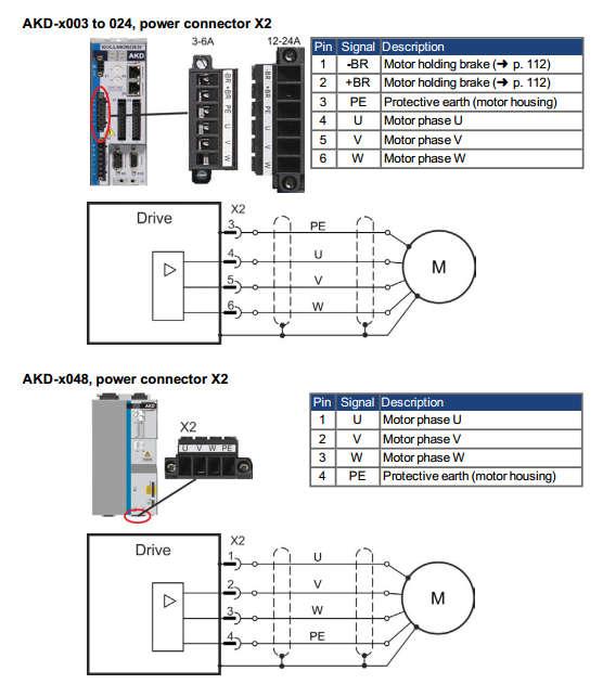
8 9. DDL Motor Coil Connections Motor Connector Pin Numbers Motor Coil Wire Color AKD Drive Connection Connector X2 1 Red U 2 White V 3 Black W Connector Shell Grn/Yel PE GND Connector Shell Violet Shield 8
9 9
 and the Product Support Package (PSP) CD-ROM packaged with the drive. Follow the installation instructions. (If in doubt, install Kollmorgen WorkBench GUI Full Version. ) 1.")
10 Configure the AKD Drive Using the Workbench Software Install AKD Workbench. The software program can be found on the website ( ( and the Product Support Package (PSP) CD-ROM packaged with the drive. Follow the installation instructions. (If in doubt, install Kollmorgen WorkBench GUI Full Version. ) 1. Safety First When first starting up the system, it is recommended to limit the peak current of the drive to a safe value and add wood blocks at each motor end stop to confirm it is operating correctly. If the motor was to run away at its full output force capability, it could cause serious injury or damage to the equipment. 10

11 2. Connect to the AKD Drive Follow the instruction from the WorkBench help file. 11

12 3. Expand Settings and Select the Motor Setup Screen 12

13 4. Select Motor from Pull Down List NOTE If the motor cannot be found in the database, Custom motors can be setup using the Edit Custom Motors tools under Edit on the tool bar. Instructions for use can be found in the WorkBench help file. 13
14 5. Select Motor Temperature Sensor Note to double-click on Motor to expand the project tree if Motor Temperature is not visible. 14
.")


15 1. Thermostat Option type TR : PTC thermistor sensor Kollmorgen DDL linear motors use a PTC thermistor sensor if the Thermostat Option selected is TR Thermistor (MOTOR.RTYPE = 0, Single PTC Thermistor ). Set the value for the MOTOR.TEMPFAULT = Thermostat Option type TS : Thermal switch Kollmorgen DDL linear motors use a thermal switch if the Thermostat Option selected is TS Thermostat (MOTOR.RTYPE = 5, Thermal Switch ) 3. No Thermal Sensor In the case a thermal sensor is not used in the application, the thermal protection feature can be defeated by setting the (MOTOR.TEMPFAULT = 0, the Fault Level ) 15

16 6. Select Feedback Type Notes on the resolution setting are explained below. 16
17 7. Configuring Encoder Feedback Resolution The encoder resolution is based on the magnet pitch of the motor divided by the encoder resolution. The units are lines/pitch. Kollmorgen DDL motors have a magnet pitch of 32 mm. For example, if the encoder has a 20 micron pitch, enter (32mm / 20 micron pitch *1000) = 1600 line count (lines per 32mm) as your encoder resolution. The following chart provides typical encoder resolution figures and their equivalent AKD value. Encoder Equivalent Resolution µm Line Count AKD Resolution lines/pitch Encoder Equivalent Resolution µm Line Count AKD Resolution lines/pitch

18 8. Test Encoder Direction and Resolution The direction of the encoder, the motor phase sequence, and hall sequence all need to match exactly. The hall phasing also needs to match the motor phasing exactly. This is very difficult to do by trial and error. Drive Direction has to be set to zero ( DRV.DIR =0 ) From the commutation drawings in Figure 2 the motor positive direction is toward the end of the motor where the wires exit the motor. The Feedback test available is the movement of the indicator on the motor feedback screen. If the encoder is counting in the wrong direction, swap the Sine+ and Sine- signal or the A and A\ signal. If this cannot be done if the Data channels of the encoder are being used. If changing the feedback direction is not possible, use Appendix A (Page 29) for 18
19 the wiring configuration of the Hall sensors and the motor power connections. 9. Checking Motor Feedback Resolution The feedback resolution can be tested by marking two lines on the magnet way 32mm apart. You can use whatever length you want, but longer is more accurate. Change the User Units to mm. If the position display does not match the distance the motor is moved, you may need to revisit the encoder scaling section of this manual or confirm the feedback device scale. 19
20 10. Check Motor Phasing of Any Servo Motor This is useful for commissioning a third-party motor, as well as any frameless Kollmorgen motor, or any servo motor for which the phasing is unknown. This part of the setup will require a two channel oscilloscope with isolated channels. Move the motor in the positive direction based on the motor manufactures specification. The AKD commutates a motor in the phase sequence of U V W in the positive direction. When determining the motor phasing, the U phase (U phase with reference to V phase) will lead the back emf voltage waveform by 120 of the V phase (V phase with reference to W phase). 20
21 While moving the motor in a positive direction the motor V phase (V phase with reference to W phase) will lead the back emf voltage waveform by 120 of W phase (W phase with reference to U phase). Use Figure 2 to determine the Hall Sensor alignment of the motor. Make sure the feedback position value (PL.FB) is counting in the positive direction. 21
22 10. Test Hall Sequence When Moving Motor in the Positive Direction The hall phasing can be check with the parameter FB1.HALLSTATE. This is a binary value, where 001 is Hall U, 010 is Hall V, and 100 is Hall W. 22
23 Hall Sensor Sequence when FeedBack (PL.FB) Is Counting Positive When Using AKD Firmware Version = or > Do not use the parameter FB1.HALLSTATE in the oscilloscope feature to monitor Hall sensor state Step(CW) FB1.HALLSTATEW FB1.HALLSTATEV FB1.HALLSTATEU Hall Sensor Sequence when FeedBack (PL.FB) Is Counting Positive When Using AKD Firmware Version < Do not use the parameter FB1.HALLSTATE in the oscilloscope feature to monitor Hall sensor state. Step(CW) FB1.HALLSTATEW FB1.HALLSTATEV FB1.HALLSTATEU
24 11. Motor Back emf And Hall Sensor Signal Alignment Figure 2 When using a Kollmorgen DDL motor, MOTOR.PHASE = 120 when the feedback direction is positive toward the Lead Exit End of motor (that is, the end of the motor where the leads come out), and when the hall alignmet and motor phasing match exactly as shown in Figure 2. 24
25 12. How to Verify the Motor s Commutation Alignment Angle (MOTOR.PHASE) Set the Wake & Shake Current WS.IMAX equal to continuous of your linear motor in the Terminal Screen. 25
26 13. Start the Wake and Shake Routine Start the Wake and Shake routine to find the MOTOR.PHASE offset value. When commissioning the linear motor system, the Wake and shake routine should be performed in several different positions of the motor s travel. The MOTOR.PHASE values should be no more than 5 degrees different in the different positions. 26

27 14. Verify the Motor is Setup Correctly by Jogging it in Both Directions Make sure the AKD drive s peak current is limited before doing this exercise. A linear motor runaway can result in damage to the system equipment or possible bodily injury. The linear motor initial commissioning is now complete! 27
28 Appendix A Configuring a DDL Liner Motor with Feedback Counting in the Opposite Direction 1. DDL Motor Coil Connections Motor Connector Pin Numbers Motor Coil Wire Color AKD Drive Connection Connector X2 1 Red W 2 White V 3 Black U Connector Shell Grn/Yel PE GND Connector Shell Violet Shield 28
29 2. DDL Motor Hall Sensor Connections Motor Connector Pin Numbers Motor Hall Effect Colors AKD Drive Connection Connector X10 Pin No. 1 Yellow 2 2 Green 1 3 Black 3 29

30 3. Checking Motor Feedback Resolution The feedback resolution can be tested by marking two lines on the magnet way 32mm apart. You can use whatever length you want, but longer is more accurate. Change the User Units to mm. If the position display does not match the distance the motor is moved, you may need to revisit the encoder scaling section of this manual or confirm the feedback device scale. 30

31 4. Check Motor Phasing of Any Servo Motor This is useful for commissioning a third-party motor, as well as any frameless Kollmorgen motor, or any servo motor for which the phasing is unknown. This part of the setup will require a two channel oscilloscope with isolated channels. Move the motor in the positive direction based on the motor manufactures specification. The AKD commutates a motor in the phase sequence of U V W in the positive direction. When determining the motor phasing, the U phase (U phase with reference to V phase) will lead the back emf voltage waveform by 120 of the V phase (V phase with reference to W phase). 31
32 While moving the motor in a positive direction the motor V phase (V phase with reference to W phase) will lead the back emf voltage waveform by 120 of W phase (W phase with reference to U phase). Use Figure 3 to determine the Hall Sensor alignment of the motor. Make sure the feedback position value (PL.FB) is counting in the positive direction. 32
33 Test Hall Sequence When Moving Motor in the Positive Direction The hall phasing can be check with the parameter FB1.HALLSTATE. This is a binary value, where 001 is Hall U, 010 is Hall V, and 100 is Hall W. 33
34 6. Monitoring the Hall Sensors States Hall Sensor Sequence when FeedBack (PL.FB) Is Counting Positive When Using AKD Firmware Version = or > Do not use the parameter FB1.HALLSTATE in the oscilloscope feature to monitor Hall sensor state Step(CW) FB1.HALLSTATEW FB1.HALLSTATEV FB1.HALLSTATEU Hall Sensor Sequence when FeedBack (PL.FB) Is Counting Positive When Using AKD Firmware Version < Do not use the parameter FB1.HALLSTATE in the oscilloscope feature to monitor Hall sensor state. Step(CW) FB1.HALLSTATEW FB1.HALLSTATEV FB1.HALLSTATEU
35 7. MOTOR BACK EMF AND HALL SENSOR SIGNAL ALIGNMENT Figure 3 When using a Kollmorgen DDL motor, MOTOR.PHASE = 120 when the feedback direction is positive toward the Lead Exit End of motor (that is, the end of the motor where the leads come out), and when the hall alignmet and motor phasing match exactly as shown in Figure 3. Return to 13. Start the Wake and Shake Routine on page 26 35
SC125MS. Data Sheet and Instruction Manual. ! Warning! Salem Controls Inc. Stepper Motor Driver. Last Updated 12/14/2004
 SC125MS Stepper Motor Driver Salem Controls Inc. Last Updated 12/14/2004! Warning! Stepper motors and drivers use high current and voltages capable of causing severe injury. Do not operate this product
3 Channel Constant Current DMX LED Driver
 3 Channel Constant Current DMX LED Driver LDMX-PWM-CC-3 2016 Digilin Australia. Document Rev : 5. 2-3 Nov ember 2016 Product spe cifications are subject to change without no tice. Table Of Contents Safety
Tuneable White DMX LED Driver
 Tuneable White DMX LED Driver LDMX-PWM-VW 2016 Digilin Australia. Document Rev : 5. 2-4 Nov ember 2016 Product spe cifications are subject to change without no tice. WAR M COOL NC Tuneable White DMX LED
SKA COMPACT. ALL IN ONE Linear Axes
 SKA COMPACT ALL IN ONE Linear Axes Cutting-edge all in one linear axis based on iron core technology. A range of three sizes with aluminium carrying structure. The power components, moving coil and magnetic
TA7262P,TA7262P(LB),TA7262F
,TA7262F") TOSHIBA BIPOLAR LINEAR INTEGRATED CIRCUIT SILICON MONOLITHIC TA7262P,TA7262P(LB),TA7262F DC MOTOR DRIVER (3 PHASE Bi DIRECTIONAL) The TA7262P / P (LB) / F are 3 Phase Bi Directional supply voltage control
TOSHIBA BIPOLAR LINEAR INTEGRATED CIRCUIT SILICON MONOLITHIC TA7262P,TA7262P(LB),TA7262F DC MOTOR DRIVER (3 PHASE Bi DIRECTIONAL) The TA7262P / P (LB) / F are 3 Phase Bi Directional supply voltage control
TPM(A) Quick Startup Guide SIEMENS SINAMICS S120
 Quick Startup Guide SIEMENS SINAMICS S120") Quick Startup Guide TPM(A) 00 110 SIEMENS SINAMICS S120 Version : 1.2 Date : 1 th December 200 File : 091_D012_0.doc Doc.No. : 091-D012-0 Technical changes reserved! Table of Contents TABLE OF CONTENTS...
Quick Startup Guide TPM(A) 00 110 SIEMENS SINAMICS S120 Version : 1.2 Date : 1 th December 200 File : 091_D012_0.doc Doc.No. : 091-D012-0 Technical changes reserved! Table of Contents TABLE OF CONTENTS...
Double Inverted Pendulum (DBIP)
") Linear Motion Servo Plant: IP01_2 Linear Experiment #15: LQR Control Double Inverted Pendulum (DBIP) All of Quanser s systems have an inherent open architecture design. It should be noted that the following
Linear Motion Servo Plant: IP01_2 Linear Experiment #15: LQR Control Double Inverted Pendulum (DBIP) All of Quanser s systems have an inherent open architecture design. It should be noted that the following
Simple circuits - 3 hr
 Simple circuits - 3 hr Resistances in circuits Analogy of water flow and electric current An electrical circuit consists of a closed loop with a number of different elements through which electric current
user's manual nx frequency converters resolver option board opt-bc
 user's manual nx frequency converters resolver option board opt-bc INDEX Document code: ud01039d Date: 18.2.2011 1. Resolver option board OPT-BC... 3 1.1 Resolver basics... 3 1.2 Resolver board features...
SKA DDL IRON CORE LINEAR MOTORS. Direct Drive Technology
 Direct Drive Technology SKA DDL IRON CORE LINEAR MOTORS Copyright 2007 Motor Power Company. All rights reserved. Contents are subjected to change without any notice. Edition 05/12 SKA DDL LINEAR MOTOR
I-FORCE Ironless linear motors
 I-FORCE Ironless linear motors Parker Trilogy s I-Force ironless linear motors offer high forces and rapid accelerations in a compact package. With forces ranging from 5.5 lbf (24.5 N) - 197.5 lbf (878.6
Sample Alignment Part
 Sample Alignment Part Contents Contents 1. How to set Part conditions...1 1.1 Setting conditions... 1 1.2 Customizing scan conditions and slit conditions... 6 2. Sample alignment sequence...13 2.1 Direct
E6C-N. Ideal for Out-of-step Detection of Stepping Motors and Position Control of Rotors and Unloaders
 Multi-turn High-precision Encoder Ideal for Out-of-step Detection of Stepping Motors and Position Control of Rotors and Unloaders Reset function for easy origin alignment when built-into equipment. Multi-turn
Sample Alignment (2D detector) Part
 Part") Sample Alignment (2D detector) Part Contents Contents 1 How to set Part conditions...1 1.1 Setting conditions... 1 1.2 Customizing scan conditions and slit conditions... 6 2 Sample alignment sequence...13
Sample Alignment (2D detector) Part Contents Contents 1 How to set Part conditions...1 1.1 Setting conditions... 1 1.2 Customizing scan conditions and slit conditions... 6 2 Sample alignment sequence...13
ISSP User Guide CY3207ISSP. Revision C
 CY3207ISSP ISSP User Guide Revision C Cypress Semiconductor 198 Champion Court San Jose, CA 95134-1709 Phone (USA): 800.858.1810 Phone (Intnl): 408.943.2600 http://www.cypress.com Copyrights Copyrights
Installation guide 862 MIT / MIR
 Installation guide 862 MIT / MIR in combination with: 864 MTT or 863 MRT or (dual) spot element November 2005 Part no. 4416.232_Rev3 Enraf BV PO Box 812 2600 AV Delft Netherlands Tel. : +31 15 2701 100
Minute Impulse Clock Controller I01DN
 99b-mi USER S MANUAL Minute Impulse Clock Controller Mon Jun 01, 2009 12:00:00 PM DST HOLD ENTER KEY TO BEGIN CANCEL HR I01DN 97 West Street Medfield, MA 02052 U.S.A. (508) 359-4396 Pg. 2 of 20 TABLE OF
Circular Motion and Centripetal Force
 [For International Campus Lab ONLY] Objective Measure the centripetal force with the radius, mass, and speed of a particle in uniform circular motion. Theory ----------------------------- Reference --------------------------
ACM-D Series (Patented)
") ACM-D Series (Patented) High Force Iron Core Brushless Linear Motor Iron core technology Low cogging force Integrated with hall sensors High force Zero net attraction force 47 ACM2-D Specifications ACM2-D-S1
ACM-D Series (Patented) High Force Iron Core Brushless Linear Motor Iron core technology Low cogging force Integrated with hall sensors High force Zero net attraction force 47 ACM2-D Specifications ACM2-D-S1
Electricity and magnetism. Verifying the Lenz Law by measuring the electric current flowing through a coil created by an external magnetic field
 Verifying the Lenz Law by measuring the electric current flowing through a coil created by an external magnetic field Dimension 2 Cross Cutting Concepts Dimension 1 Science and Engineering Practices Electricity
Energy. This provides a practical measure of the usefulness of a machine. The useful energy transfer in a generator can be represented by:
 Sensors: Loggers: Voltage, Current, Motion Any EASYSENSE Physics Logging time: 10 seconds 44a Efficiency of an electric generator Read Machines use energy transfers to achieve a useful job of work. No
Operation Manual. SPECTRO-NANO4 Nucleic Acid Analyzer PLEASE READ THIS MANUAL CAREFULLY BEFORE OPERATION
 Operation Manual SPECTRO-NANO4 Nucleic Acid Analyzer PLEASE READ THIS MANUAL CAREFULLY BEFORE OPERATION 3, Hagavish st. Israel 58817 Tel: 972 3 5595252, Fax: 972 3 5594529 mrc@mrclab.com MRC. 4.18 Foreword
E2T0 DVP
 29-5-26 5116868-E2T DVP-11363-1 ENGLISH Thank you for choosing Delta s DVP series PLC. DVP4TC-E2 temperature measurement module receives 4 points of external thermocouple temperature sensors (J-type, K-type,
44 Force extension characteristics for a spring / elastic material
 Sensors: Loggers: Force, Motion Any EASYSENSE Physics Logging time: SnapShot 44 Force extension characteristics for a spring / elastic material Read If a spring or any elastic material is being used in
BioMechanics and BioMaterials Lab (BME 541) Experiment #5 Mechanical Prosperities of Biomaterials Tensile Test
 Experiment #5 Mechanical Prosperities of Biomaterials Tensile Test") BioMechanics and BioMaterials Lab (BME 541) Experiment #5 Mechanical Prosperities of Biomaterials Tensile Test Objectives 1. To be familiar with the material testing machine(810le4) and provide a practical
BioMechanics and BioMaterials Lab (BME 541) Experiment #5 Mechanical Prosperities of Biomaterials Tensile Test Objectives 1. To be familiar with the material testing machine(810le4) and provide a practical
Technical Note Series
 Technical Note Series INCLINOTRAC (T7650) & DUAL-INCLINOTRAC (T7655) S TN0011-0 0 I n c l i n o T r a c / D u a l - I n c l i n o T r a c Page 2 IMPORTANT OPERATION INFORMATION Type BF Equipment Internally
Digital Current Transducer HO-SW series I P N = A. Ref: HO 100-SW; HO 150-SW; HO 200-SW; HO 250-SW
 Digital Current Transducer HO-SW series I P N = 100... 250 A Ref: HO 100-SW; HO 150-SW; HO 200-SW; HO 250-SW Bitstream output from on onboard Sigma Delta modulator. For the electronic measurement of current:
Charge to Mass Ratio of The Electron
 Physics Topics Charge to Mass Ratio of The Electron If necessary, review the following topics and relevant textbook sections from Serway / Jewett Physics for Scientists and Engineers, 9th Ed. Electric
B = 8 0 NI/[r (5) 3/2 ],
![B = 8 0 NI/[r (5) 3/2 ],](/thumbs/80/82433821.jpg "B = 8 0 NI/[r (5) 3/2 ],") ELECTRON BEAM IN A MAGNETIC FIELD Introduction: A charged body moving relative to a magnetic field experiences a force which is perpendicular to both the velocity of the particle and to the magnetic field.
ELECTRON BEAM IN A MAGNETIC FIELD Introduction: A charged body moving relative to a magnetic field experiences a force which is perpendicular to both the velocity of the particle and to the magnetic field.
DC motor / generator. Jeffrey A. Meunier
 DC motor / generator Jeffrey A. Meunier jeffm@engr.uconn.edu Electric motor An electric motor is used to convert electrical energy into mechanical energy. Electric motor An electric motor is used to convert
Operating Instructions for Digital Manometer. Model: MAN-SD
 Operating Instructions for Digital Manometer Model: MAN-SD 1. Contents 1. Contents...2 2. Note...3 3. Instrument Inspection...3 4. Regulation Use...4 5. Operating Principle...4 6. Mechanical Connection...5
ph Probe ReallyEasyData com
 ph Probe 9200001 Uses Whether you re monitoring ph for chemistry, physical science, life science, or earth science activity, this ph meter offers accurate readings in a convenient format. Use the RED ph
From this analogy you can deduce some rules that you should keep in mind during all your electronics work:
 Resistors, Volt and Current Posted on April 4, 2008, by Ibrahim KAMAL, in General electronics, tagged In this article we will study the most basic component in electronics, the resistor and its interaction
Data Logger V2. Instruction Manual
 Data Logger V2 Instruction Manual Joe Holdsworth 7-29-2018 Contents Revision History... 2 Specifications... 3 Power Limits... 3 Data Rates... 3 Other Specifications... 3 Pin Outs... 4 AS218-35SN... 4 AS210-35SN...
Motors Automation Energy Transmission & Distribution Coatings. Servo Drive SCA06 V1.5X. Addendum to the Programming Manual SCA06 V1.
 Motors Automation Energy Transmission & Distribution Coatings Servo Drive SCA06 V1.5X SCA06 V1.4X Series: SCA06 Language: English Document Number: 10003604017 / 01 Software Version: V1.5X Publication Date:
Quick Start Guide New Mountain Visit our Website to Register Your Copy (weatherview32.com)
") Quick Start Guide New Mountain Visit our Website to Register Your Copy (weatherview32.com) Page 1 For the best results follow all of the instructions on the following pages to quickly access real-time
Quick Start Guide New Mountain Visit our Website to Register Your Copy (weatherview32.com) Page 1 For the best results follow all of the instructions on the following pages to quickly access real-time
Magnetism. a) Ferromagnetic materials are strongly attracted to magnets. b) Paramagnetic materials are weakly attracted to magnets
 Ferromagnetic materials are strongly attracted to magnets. b) Paramagnetic materials are weakly attracted to magnets") Magnetism Types of Magnetic Materials Magnetic substances can be classified into three basic groups, according to their response to a magnet. Note the strength and direction of the interaction. a) Ferromagnetic
Magnetism Types of Magnetic Materials Magnetic substances can be classified into three basic groups, according to their response to a magnet. Note the strength and direction of the interaction. a) Ferromagnetic
EC 60 TM 200W 48V. with brushless drive. brushless small & compact maintenance-free Protection IP65. Ordering Data
 EC-Servo motors with brushless drive EC 0 TM 200W 48V brushless small & compact maintenance-free Protection IP Ordering Data characteristics permanently energized -phase synchronous motor incremental position
ph electrode Instruction Manual For use with the RAH-210 & RPH-250
 ph electrode Instruction Manual For use with the RAH-210 & RPH-250 The information in this manual was current at the time of printing. The most current versions of all Hydro Instruments manuals can be
X-LSM-E Series: Miniature motorized linear stages with built-in motor encoder and controllers
 X-LSM-E Series: Miniature motorized linear stages with built-in motor encoder and controllers 25, 50, 100, 150, 200 mm travel 10 kg load capacity Up to 104 mm/s speed and up to 55 N thrust Built-in controller;
O P E R A T I N G M A N U A L
 OPERATING MANUAL WeatherJack OPERATING MANUAL 1-800-645-1061 The baud rate is 2400 ( 8 bits, 1 stop bit, no parity. Flow control = none) To make sure the unit is on line, send an X. the machine will respond
Elementary charge and Millikan experiment Students worksheet
 Tasks This experiment deals with the observation of charged oil droplets, which are accelerated between two capacitor plates.. Measure some rise and fall times of oil droplets at different voltages. Determine
Blackbody Radiation EX-9920 ScienceWorkshop Page 1 of 8. Blackbody Radiation
 Blackbody Radiation EX-9920 ScienceWorkshop Page 1 of 8 EQUIPMENT Blackbody Radiation INCLUDED: 1 Prism Spectrophotometer Kit OS-8544 1 Optics Bench (60 cm) OS-8541 1 Spectrophotometer Accessory Kit OS-8537
Alpha-Energies of different sources with Multi Channel Analyzer
 Physical Structure of Matter Radioactivity Alpha-Energies of different sources with Multi Channel Analyzer What you can learn about Decay series Radioactive equilibrium Isotopic properties Decay energy
Assembly and Operation Manual. April 2016
 Assembly and Operation Manual April 2016 Table of Contents What is in the OurWeather Box? 3 Step by Step Assembly 13 Building the Weather Sensors 18 Testing the OurWeather Weather Station 28 Power Up OurWeather
Evaluation Board for 8-/10-/12-Bit, Parallel Input, Dual-Channel, Current Output DAC EVAL-AD5428/AD5440/AD5447EB
 Evaluation Board for 8-/0-/-Bit, Parallel Input, Dual-Channel, Current Output DAC EVAL-AD58/AD50/AD5EB FEATURES Operates from dual ± V and 5 V supplies On-board reference and output amplifiers Direct hookup
QDTL. Liquid Mass Transfer and Diffusion Coefficient Unit PROCESS DIAGRAM AND UNIT ELEMENTS ALLOCATION. Electronic console
 Engineering and Technical Teaching Equipment Liquid Mass Transfer and Diffusion Coefficient Unit QDTL Electronic console PROCESS DIAGRAM AND UNIT ELEMENTS ALLOCATION ISO 9001: Quality Management (for Design,
Magnetic Fields. Experiment 1. Magnetic Field of a Straight Current-Carrying Conductor
 General Physics Lab Department of PHYSICS YONSEI University Lab Manual (Lite) Magnetic Fields Ver.20181029 NOTICE This LITE version of manual includes only experimental procedures for easier reading on
PHY 123 Lab 9 Simple Harmonic Motion
 PHY 123 Lab 9 Simple Harmonic Motion (updated 11/17/16) The purpose of this lab is to study simple harmonic motion of a system consisting of a mass attached to a spring. You will establish the relationship
Lamp and Control Panel (Lamp Panel)
") www.reinhausen.com Lamp and Control Panel (Lamp Panel) Operating Instructions BA 47/0 EN NOTE! Changes may have been made to a product after going to press with this documentation. We expressly reserve
www.reinhausen.com Lamp and Control Panel (Lamp Panel) Operating Instructions BA 47/0 EN NOTE! Changes may have been made to a product after going to press with this documentation. We expressly reserve
GS110. IR Thermal Imaging System for Low-Emissivity Glass with Automatic Emissivity Correction. Manual Addendum
 GS110 IR Thermal Imaging System for Low-Emissivity Glass with Automatic Emissivity Correction Manual Addendum Rev. B 10/2006 1 Safety Instructions All notices regarding safety and acceptable operation
Determination of the Rydberg constant, Moseley s law, and screening constant (Item No.: P )
") Determination of the Rydberg constant, Moseley s law, and screening constant (Item No.: P2541001) Curricular Relevance Area of Expertise: ILIAS Education Level: Physik Topic: Hochschule Subtopic: Moderne
Determination of the Rydberg constant, Moseley s law, and screening constant (Item No.: P2541001) Curricular Relevance Area of Expertise: ILIAS Education Level: Physik Topic: Hochschule Subtopic: Moderne
ME 4/549 Lab Assignment 5: Single Block Experiment Spring 2006 due 1 June 2006
 ME 4/549 Lab Assignment 5: Single Block Experiment Spring 2006 due 1 June 2006 version May 23, 2006 1 Objective The objective of the laboratory exercise is to measure the convective heat transfer coefficient
Chapter 7 Direct-Current Circuits
 Chapter 7 Direct-Current Circuits 7. Introduction... 7. Electromotive Force... 7.3 Resistors in Series and in Parallel... 4 7.4 Kirchhoff s Circuit Rules... 6 7.5 Voltage-Current Measurements... 8 7.6
Driven Harmonic Oscillator
 Driven Harmonic Oscillator Physics 6B Lab Experiment 1 APPARATUS Computer and interface Mechanical vibrator and spring holder Stands, etc. to hold vibrator Motion sensor C-209 spring Weight holder and
For the electronic measurement of current: DC, AC, pulsed..., with galvanic separation between the primary and the secondary circuit.
 Current Transducer HO-NP series I P N = 4, 6, 12, 15 A Ref: HO 4-NP, HO 6-NP, HO 12-NP, HO 15-NP For the electronic measurement of current: DC, AC, pulsed..., with galvanic separation between the primary
Exercise 1: Capacitors
 Capacitance AC 1 Fundamentals Exercise 1: Capacitors EXERCISE OBJECTIVE When you have completed this exercise, you will be able to describe the effect a capacitor has on dc and ac circuits by using measured
Operating instructions Magnetic-inductive flow sensor SM6004 SM7004 SM / / 2014
 Operating instructions Magnetic-inductive flow sensor SM6004 SM7004 SM8004 80003223 / 00 05 / 2014 Contents 1 Preliminary note...3 1.1 Symbols used...3 2 Safety instructions...4 3 Functions and features...5
CHV Series Vector Control Inverter Options. Operating Instructions for Tension Control Card
 CHV Series Vector Control Inverter Options Operating Instructions for Control Card 1. Model and Specifications 1.1 Model The model of tension card is CHV00ZL. CHV series inverter can conduct constant
NOVALYNX CORPORATION MODEL 110-WS-16BP BAROMETRIC PRESSURE SENSOR INSTRUCTION MANUAL
 NOVALYNX CORPORATION MODEL 110-WS-16BP BAROMETRIC PRESSURE SENSOR INSTRUCTION MANUAL REVISION DATE: OCT 2005 Receiving and Unpacking Carefully unpack all components and compare to the packing list. Notify
TOPCNC TC55V Instruction Manual
 TOPCNC TC55V Instruction Manual 1. Product Introduction TC55E is an upgrading version of TC55. It is equipped with 3.5 inch color screen, RS 485 communication, Chinese/English Switch, and USB connection.
UNIVERSAL SIGNAL INTERFACE UNIT
 SGI- rev. A UNIVERSAL SIGNAL INTERFACE UNIT This unit can recalibrate a speedometer signal or convert a speed signal from one type to another type. The different functions it can perform are as follows:.
Lab 1 Uniform Motion - Graphing and Analyzing Motion
 Lab 1 Uniform Motion - Graphing and Analyzing Motion Objectives: < To observe the distance-time relation for motion at constant velocity. < To make a straight line fit to the distance-time data. < To interpret
RC Circuit (Power amplifier, Voltage Sensor)
") Object: RC Circuit (Power amplifier, Voltage Sensor) To investigate how the voltage across a capacitor varies as it charges and to find its capacitive time constant. Apparatus: Science Workshop, Power
Object: RC Circuit (Power amplifier, Voltage Sensor) To investigate how the voltage across a capacitor varies as it charges and to find its capacitive time constant. Apparatus: Science Workshop, Power
Structure Monitoring Technology. Features. Ordering Information. Trigger Tape. A2 Pulse Counter (Optional) Solar Radiation Sensor
 Solar Radiation Sensor") Rain detection sensor General Description Driving rain and its effective management are critical factors in determining the durability of building enclosures. An accurate measurement of driving rain can
Rain detection sensor General Description Driving rain and its effective management are critical factors in determining the durability of building enclosures. An accurate measurement of driving rain can
GCSE 0241/02 ADDITIONAL SCIENCE HIGHER TIER PHYSICS 2
 Surname Centre Number Candidate Number Other Names 0 GCSE 0241/02 ADDITIONAL SCIENCE HIGHER TIER PHYSICS 2 A.M. WEDNESDAY, 30 January 2013 45 minutes ADDITIONAL MATERIALS In addition to this paper you
Technical Description
 Overview It is being digitalized and accelerated with builtin micro processor because of development of computer. It is widely used in industrial NC, ROBOT, servo motors and OA equipment in order to detect
SKA DDL IRON CORE LINEAR MOTORS. Direct Drive Technology
 Direct Drive Technology SKA DDL IRN CRE LINEAR MTRS Copyright 2007MotorPowerCompany.Allrightsreserved.Contentsaresubjectedtochangewithoutany n o t i c e.e d i tion01/19 SKA DDL LINEAR MTR Precision, dynamics,
Single cam type. Double cam type. Grip force N. Type Model/size Stroke Screw type straight style. Screw type tee style
 Type Model/size Stroke -SS-0-N. -SS-0-N. Single cam type -SS- 7. -SS-. -SS-4. -SD-0 Double cam type -SD- -SD-4. Screw type straight style Screw type tee style -FS- -FT- -FS- -FT- 0.9 1. 1.. 1. 4 Grip forcen
Quick Start and Troubleshooting Guide
 Quick Start and Troubleshooting Guide By RXDesign Copyright July 2003 Quick Start and Troubleshooting Guide Rev 2 Welcome... tto tthe worrl ld off tthe CAT. 1 Addendum - Quick Start Alright... it is installed!
Dynamic Self Assembly of Magnetic Colloids
 Institute of Physics, University of Bayreuth Advanced Practical Course in Physics Dynamic Self Assembly of Magnetic Colloids A. Ray and Th. M. Fischer 3 2012 Contents 1. Abstract 3 2. Introduction 3 3.
Rotary Motion Servo Plant: SRV02. Rotary Experiment #01: Modeling. SRV02 Modeling using QuaRC. Student Manual
 Rotary Motion Servo Plant: SRV02 Rotary Experiment #01: Modeling SRV02 Modeling using QuaRC Student Manual SRV02 Modeling Laboratory Student Manual Table of Contents 1. INTRODUCTION...1 2. PREREQUISITES...1
PHY222 Lab 2 - Electric Fields Mapping the Potential Curves and Field Lines of an Electric Dipole
 Print Your Name PHY222 Lab 2 - Electric Fields Mapping the Potential Curves and Field Lines of an Electric Dipole Print Your Partners' Names Instructions January 23, 2015 Before lab, read the Introduction,
Dielectric Analysis of Solid Insulations
 using Dielectric Test Fixture 16451B from Keysight By Britta Pfeiffer 2018 by OMICRON Lab V2.0 Visit www.omicron-lab.com for more information. Contact support@omicron-lab.com for technical support. Page
Preliminary Product Information. LIC 4000 Series Exposed Absolute Linear Encoders
 Preliminary Product Information LIC 4000 Series Exposed Absolute Linear Encoders April 2009 LIC 4000 Series Exposed absolute linear encoders Measuring lengths up to 27 m Measuring steps to 0.001 µm (1
Real Analog - Circuits 1 Chapter 6: Lab Projects
 6.3.2: Leakage urrents and Electrolytic apacitors eal Analog ircuits 1 hapter 6: Lab Projects Overview: Voltagecurrent relationships for ideal capacitors do not always adequately explain measured capacitor
ACE Control System. 1.0-m Pomona College Telescope Table Mountain Observatory ACE User Manual April 2005 Revision All rights reserved.
 ACE Control System 1.0-m Pomona College Telescope Table Mountain Observatory ACE User Manual April 2005 Revision 1.1 1999-2005. All rights reserved. Astronomical Consultants & Equipment, Inc. P.O. Box
3. The figure above shows two pith balls suspended by threads from a support. In the figure,
 3. The figure above shows two pith balls suspended by threads from a support. In the figure, Student ID: 22133336 Exam: 002901RR - Electronics Basics When you have completed your exam and reviewed your
Exercise 2-2. Titration of a Strong Acid EXERCISE OBJECTIVES
 Exercise 2-2 Titration of a Strong Acid EXERCISE OBJECTIVES To describe the effect of a ph variation on a chemical indicator; To titrate water containing a strong base solution with a strong acid solution;
Dimensional drawing face mount flange radial. R = bending radius min. 40 mm. Dimensional drawing face mount flange axial
 Incremental Encoder DRS/DRS, face mount flange up to 8,2 Dimensional drawing face mount flange radial Incremental Encoder Connector or cable outlet Protection class up to IP s TTL and HTL Zero-Pulse-Teach
Experiment A11 Chaotic Double Pendulum Procedure
 AME 21216: Lab I Fall 2017 Experiment A11 Chaotic Double Pendulum Procedure Deliverables: Checked lab notebook, plots with captions Background Measuring and controlling the angular position and velocity
Atomic and nuclear physics
 Atomic and nuclear physics X-ray physics Physics of the atomic shell LEYBOLD Physics Leaflets Moseley s law and determination of the Rydberg constant P6.3.3.6 Objects of the experiment Measuring the K-absorption
Ref: HLSR 16-PW; HLSR 32-PW; HLSR 40-PW-000; HLSR 50-PW-000,
 Digital Current Transducer HLSR-PW series I P N = 16... 50 A Ref: HLSR 16-PW; HLSR 32-PW; HLSR 40-PW-000; HLSR 50-PW-000, Bitstream output from on onboard Sigma Delta modulator. For the electronic measurement
BEFORE USE... POINTS OF CAUTION COMPONENT IDENTIFICATION INSTRUCTION MANUAL MODEL R7K4DH-1-DAC32D R7K4DH-1-DAC32D
 INSTRUCTION MANUAL PNP DISCRETE INPUT & PNP TRANSISTOR OUTPUT MODULE, 6 points each (High-speed Link System, e-con connector) R7KDH--DACD MODEL R7KDH--DACD BEFORE USE... Thank you for choosing M-System.
AC Synchronous Motors
 AC Synchronous Motors A C S Y N C H R O N O U S M O T O R S AC Synchronous Motors Kollmorgen AC synchronous motors are high pole count motors that naturally turn at slower speeds (72 or 60 rpm). at 72
Alpha-energies of different sources with Multi Channel Analyzer (Item No.: P )
") Alpha-energies of different sources with Multi Channel Analyzer (Item No.: P2522015) Curricular Relevance Area of Expertise: ILIAS Education Level: Physik Topic: Hochschule Subtopic: Moderne Physik Experiment:
Alpha-energies of different sources with Multi Channel Analyzer (Item No.: P2522015) Curricular Relevance Area of Expertise: ILIAS Education Level: Physik Topic: Hochschule Subtopic: Moderne Physik Experiment:
In-System Serial Programming (ISSP) Guide
 Guide") CY3207ISSP In-System Serial Programming (ISSP) Guide Spec. # 001-15301 Rev. ** Cypress Semiconductor 198 Champion Court San Jose, CA 95134-1709 Phone (USA): 800.858.1810 Phone (Intnl): 408.943.2600 http://www.cypress.com
CY3207ISSP In-System Serial Programming (ISSP) Guide Spec. # 001-15301 Rev. ** Cypress Semiconductor 198 Champion Court San Jose, CA 95134-1709 Phone (USA): 800.858.1810 Phone (Intnl): 408.943.2600 http://www.cypress.com
Engineering Data AC Servo Actuators LynxDrive
 Engineering Data AC Servo Actuators LynxDrive More information on our servo products can be found HERE! Contact us today! Contents 1. General... 3 1.1 Description of Safety Alert Symbols...4 1.2 Disclaimer
HVAC Electrical Wiring Diagrams / Ohm s Law / Sequence of Operation RV
 PLEASE DO NOT BOOKMARK ANY ANYTIMECE WEBPAGES! Our system will remember the last page you viewed when logging out and back in but please DO NOT exit out when taking a test. Your place will NOT be saved.
224 g (Total 1 mark) A straight line in a direction opposite to that of the field.
 A straight line in a direction opposite to that of the field.") Q1. The diagram shows a rigidly-clamped straight horizontal current-carrying wire held mid-way between the poles of a magnet on a top pan balance. The wire is perpendicular to the magnetic field direction.
Q1. The diagram shows a rigidly-clamped straight horizontal current-carrying wire held mid-way between the poles of a magnet on a top pan balance. The wire is perpendicular to the magnetic field direction.
POINTS OF CAUTION BEFORE USE...
 INSTRUCTION MANUAL NPN DISCRETE INPUT & NPN TRANSISTOR OUTPUT MODULE, 6 points each (-I/-II, e-con connector) MODEL BEFORE USE... Thank you for choosing M-System. Before use, check the contents of the
Exploring the Poles (Without Leaving Your Classroom!)
") Exploring the Poles (Without Leaving Your Classroom!) Computer 37 Magnets have north and south poles. Do you think that the poles of differently shaped magnets are in different places? In this activity,
Exploring the Poles (Without Leaving Your Classroom!) Computer 37 Magnets have north and south poles. Do you think that the poles of differently shaped magnets are in different places? In this activity,
DRS 61: Incremental encoders, number of lines and zero pulse width freely programmable DRS 60: Incremental Encoders with Zero-Pulse-Teach
 NEW DRS : Incremental encoders, number of lines and zero pulse width freely programmable DRS : s with Zero-Pulse-Teach Further highlights of this generation of encoders: Simple zero-pulse-teach by pressing
Charge to Mass Ratio of The Electron
 Introduction Charge to Mass Ratio of The Electron The electron was first discovered by Sir J.J. Thomson in 1897 at the Cavendish Laboratory in Cambridge, England. His experimental apparatus is not very
HALL EFFECT IN SEMICONDUCTORS
 Warsaw University of Technology Faculty of Physics Physics Laboratory I P Andrzej Kubiaczyk 30 HALL EFFECT IN SEMICONDUCTORS 1. ackground 1.1. Electron motion in electric and magnetic fields A particle
3.3V Power Supply Isolated Current Sensor with Common Mode Field Rejection
 Fully Integrated Current Sensor IC 3.3V Power Supply Isolated Current Sensor with Common Mode Field Rejection Description The Senko Micro s provides economical and precise solutions for AC or DC current
Biot-Savart Law Performing various measures to study the magnetic field intensity variations around an inducting coil
 field intensity variations around an inducting coil Objective The goal of the activity is to investigate the surroundings of an isolated copper coil, fed with a low voltage direct current source. Using
WeatherHawk Weather Station Protocol
 WeatherHawk Weather Station Protocol Purpose To log atmosphere data using a WeatherHawk TM weather station Overview A weather station is setup to measure and record atmospheric measurements at 15 minute
A Rain Sensitive House Window Closes Automatically When Raining
 A Rain Sensitive House Window Closes Automatically When Raining House windows are sometimes opened when it rains and no body around to close them allowing rain going in side and damage the house. Information
PTC-TestBench-Magnetic
 Features and Benefits Utility to make first magnetic evaluations 0 -SIP-VA 0 -SIP-VA 0 -SIP-VA 0 SO 0 TSSOP Easy to modify or make own socket board Applications Additional utility for PTC0 in order to