ALIGNMENT OF THE SPARC LINEAR ACCELERATOR. M. Esposito, M. Paris, F. Sgamma, S. Tomassini, M. Troiani, (INFN LNF) Abstract
|
|
|
- Rhoda Alexander
- 5 years ago
- Views:
Transcription
 Abstract The SPARC project is a collaboration among ENEA, INFN, CNR and Rome Tor Vergata University on an R & D activity oriented to the development of a high-brightness")
1 SPARC-ME-10/ January 2010 ALIGNMENT OF THE SPARC LINEAR ACCELERATOR M. Esposito, M. Paris, F. Sgamma, S. Tomassini, M. Troiani, (INFN LNF) Abstract The SPARC project is a collaboration among ENEA, INFN, CNR and Rome Tor Vergata University on an R & D activity oriented to the development of a high-brightness photoinjector to drive SASE-FEL experiments [1]. The installation of the accelerator in the SPARC building has begun in 2005 and the last assembling and alignment operations have been accomplished in This paper describes the various steps of the installation and provides the fiducialization and layout data necessary for the alignment of the SPARC components.
2 2

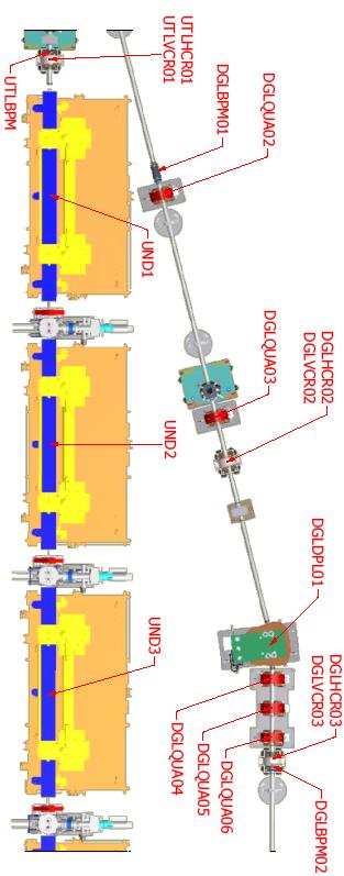
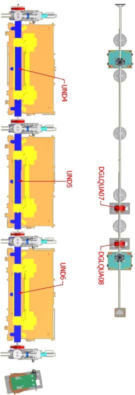
3 3 1 INTRODUCTION The SPARC machine has been installed in a rectangular hall with a total length of 36m and a width of 14m. The building was built more than 20 years ago and it is supposed to be stable. The SPARC complex is composed of an RF gun driven by a Ti:Sa laser producing 10ps flat top pulses that hit on a photocathode. The outcoming beam is injected into three SLACtype accelerating sections to feed a 6-module 12m long undulator. The accelerator layout also includes a dogleg line used for beam compression studies and other experiments. All the activity on the undulators and on the undulator line, installation and alignment included, is under the responsibility of ENEA and will not be described in this paper. The alignment of the whole accelerator is based on the use of a network of nodes as a reference frame. Therefore the first step was to accurately design, install and qualify a reference network. The second step was the fiducialisation of all magnetic and RF components in order to determine their magnetic (or mechanical) geometry with respect to targetable fiducial markers. At last the alignment of all components was performed, with a first rough and quick positioning and a subsequent precision alignment using surveying instruments. A more detailed description of the procedure is given in the following paragraphs. 2 THE REFERENCE NETWORK A network of reference nodes has been built inside the SPARC hall and it represents the reference frame for all alignment and surveying operations. The network was initially studied and designed to allow alignment and surveying activity performed by means of optical instruments (level, theodolite and total station) [2]. For this reason the network is made of a primary group of nodes which lie on two straight and parallel lines. This primary group of nodes is made of 4 pillar sockets and 17 ground sockets. A schematic layout of the SPARC reference network is shown in Fig. 1. Fig. 1: Schematic layout of the SPARC reference network
 consists of a precise and well-finished conical surface machined in a metallic plate equipped with a fine adjustment system, necessary for initial positioning.")
 or optical instruments (theodolites, levels or total stations) by means of tribrachs which allow centering and repeatable positioning. Fig.")

4 4 The standard LNF pillar socket (Fig. 2) consists of a precise and well-finished conical surface machined in a metallic plate equipped with a fine adjustment system, necessary for initial positioning. In this kind of socket it is possible to place either targets (3.5 inch Taylor Hobson spheres or 1.5 inch Corner Cube Reflectors) or optical instruments (theodolites, levels or total stations) by means of tribrachs which allow centering and repeatable positioning. Fig. 2: Standard LNF pillar socket The ground sockets consist of iron cylindrical elements with a conical cradle where 3.5 radius spheres can be placed. The ground sockets are installed and positioned using supporting devices equipped with adjustment screws which can be removed after having blocked the sockets in position by means of a resin. Fig. 3: Ground Sockets Three more sockets have been mounted on brackets (Fig. 3) on a side of the accelerator hall. By placing optical instruments on tribrachs inserted in these sockets it is possible to perform triangulation checks of the network. Moreover they provide comfortable fixed and qualified sites for optical instrument positioning for alignment and surveying operations. Fig. 4: Bracket Sockets
. Fig.")
 the LNF were not in possession of a laser tracker, therefore the measurements had to be rented.")
5 5 A first complete campaign of measurements has been performed by means of theodolites, total station and optical levels. The data have then been analyzed using STAR*NET software. A best-fitting solution of the network has been calculated and the error ellipses of measurements for each point have been evaluated exploiting the redundancy of measurements (Fig.5). Fig. 5: Network of Optical Measurements Subsequently other accurate and complete measuring campaigns have been carried out using a laser tracker. At the time of this first measuring campaign (summer 2005) the LNF were not in possession of a laser tracker, therefore the measurements had to be rented. On this occasion some other secondary nodes, well distributed on the walls of the SPARC hall, have been added to the network. The latter consist in precisely machined steel cylindrical sockets, with an 8mm internal diameter, embedded in the walls (blue dots in Fig. 1). The use of these sockets, capable of housing only CCR targets by means of appropriate CCR holders (Fig. 6), provided a cheap but efficient solution to have a denser network. The secondary nodes have been added in anticipation of a more intense future use of laser trackers for surveying and alignment operations. Fig. 6: Secondary Socket and CCR placed in a Secondary Socket with a CCR holder


6 6 Three complete campaigns of laser tracker measurements of the network have been performed from July to November Data have been analyzed and comparisons show that the differences never exceed 0.15mm and are mainly lower than 0.10mm.

7 7 Level measurements of the primary nodes have been performed also by means of optical levels. The table below shows the results of three sets of measurements performed independently by three different operators. The data coming from the laser tracker measurements have been analyzed and treated by means of the Leica Axyz software [3], and have produced the reference table of network node coordinates (table 1). The coordinates are referred to the SPARC Coordinate System (SCS) which is a right handed Cartesian coordinate system (Fig.7) defined by the following parameters: NODE X Y Z B The height of node 1 above the beam horizontal plane (700mm) has been arbitrarily chosen. The z coordinates of nodes 10 and B1 come from optical level measurements, while the y coordinate of node 10 has been arbitrarily set.
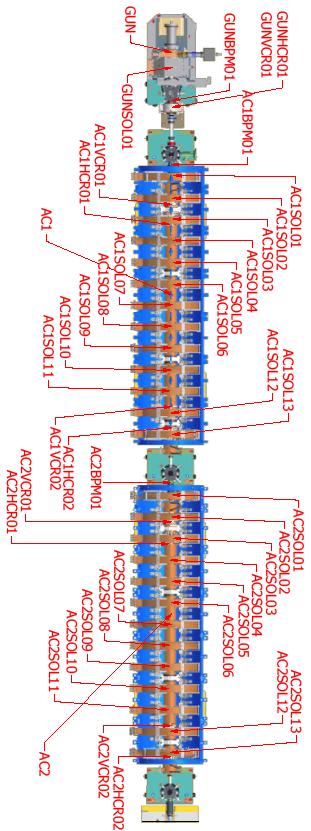
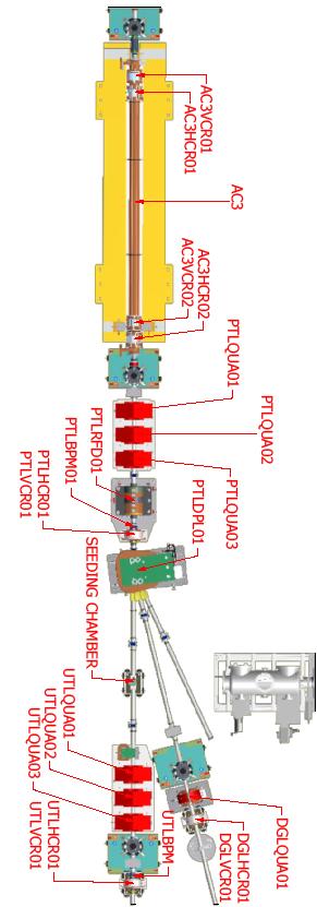
8 8 The last seven nodes in table1 (nodes from N1 to N7) have been introduced into the network and qualified subsequently (August 2007), when the removal of the four pillar nodes (1,B1,10 and 14) has been necessary for safety reasons (after the installation of machine components had been completed, the path to the emergency exits had become too narrow). 3 MACHINE LAYOUT A layout of the SPARC accelerator is shown in Fig.7. As it has been briefly described before the machine is made of a 1.6 cells s-band RF gun driven by a Ti:Sa laser. The beam coming out of the gun is then injected into three SLAC-type accelerating sections, the first two of which are embedded in 2 arrays of 13 solenoids each, required to produce a magnetic field for additional focusing in order to comply with the Ferrario working point matching conditions for emittance compensation [4]. Along the beam line, after the linac, there is an RF deflector necessary for the characterization of the longitudinal and transverse phase space of the beam and a seeding chamber, necessary to match the electron beam with a seeding laser, allowing the facility to generate seeded FEL emissions as well. The electron beam is at last driven through a 6-module 12m long undulator. The accelerator layout also includes a dogleg line used for beam compression studies and other experiments. The latter contains 2 dipole magnets, which produce the 2 14 bendings of the beam line, 8 quadrupoles and several other devices for diagnostics. Fig. 7: SPARC Layout The nominal positions of the center points of the accelerator components are listed in table 2. Their coordinates are referred to the SCS which has been defined and described in paragraph 2 and is shown in Fig. 7 (red arrows).


9 9 4 FIDUCIALIZATION OF COMPONENTS Great attention and care has been given to the fiducialization of SPARC components. As a matter of fact the correct fiducialization of components is as important as their correct positioning since an error in either task will affect the particles trajectory and these errors cannot be distinguished. Part of the SPARC components were pre-existing magnets or RF devices, previously installed on other accelerators, another part has been designed and built anew. Fiducialization data for pre-existing components were already known and just had to be checked, and updated if necessary. For newly built components the reference markers have been specifically designed always keeping in mind that fiducials must: be clearly and comfortably visible during both fiducialization process and alignment operations in the accelerator hall. be extremely stable have, as much as possible, a symmetrical distribution around the component axis. In some cases we have manufactured and fiducialized some auxiliary alignment tools, designed to be attached to the component they were built for, only during the alignment operation. The referencing of fiducial markers with respect to the geometrical axis of components and the checking of data for pre-existing components has been in most part performed by means of laser tracker measurements exploiting the tracking capabilities of this instrument and the versatility of leica Axyz software which offers tools for many types of geometrical analyses. For a part of the newly built components this operation has been accomplished by means of tactile probe 3D coordinate measuring machines in outsourcing. In these cases data on fiducial marker positions, with certified accuracy, have been provided. In the following paragraphs the fiducialization procedures, component by component (for all the components whose alignment operations were under the responsibility of INFN) will be described showing the positions of the reference markers with respect to local coordinate systems. The fiducialization of the focusing solenoids for the first two accelerating sections has been already described and shown in detail in [5] and will not be considered here. 4.1 Gun and Gun Solenoid The gun and gun solenoid have been aligned on the basis of design data. The positions of the reference markers with respect to the geometrical axes have been obtained from the drawings. Consistency of design data with LT measured reference marker coordinates has been verified, but no direct fiducialization has been carried out because installation and alignment of the gun began before purchasing the LT. 4.2 Accelerating sections


10 Accelerating Sections Two of the three accelerating sections of the SPARC linac have been delivered to LNF by Mitsubishi, while the third one comes from SLAC as part of a collaboration agreement. The two Mitsubishi sections have been fiducialized by LT measurements. A continuous mode acquisition of points on the cylindrical surface has allowed to determine the section axis on which the coordinate system has been built. Since these two accelerating sections are surrounded by an array of coils, it has been necessary to build some specific alignment tools (the plates shown in Fig. 8) to make the alignment operations easier and more comfortable, otherwise the reference markers would have been hardly visible after the installation. The SLAC accelerating section is not embedded in focusing solenoids and its external surface is always clearly visible, therefore it has been possible to perform its alignment operations just by surveying the external cylindrical surface of the section. Fig. 8: Alignment tools with fiducial markers mounted on the Mitsubishi accelerating section


.")
11 Dipole Magnets The SPARC dipoles were pre-existing magnets, previously installed on the LISA accelerator. The fiducialization data were retrieved from their datasheets and a check of the reference marker positions was performed by means of LT measurements. Fig. 9: Dipole magnet 4.3 Quadrupole Magnets The SPARC quadrupoles too were pre-existing components, but some new alignment tools have been added to them (the alignment plate in Fig. 10). A new fiducialization of all the quadrupole magnets has therefore been necessary. The latter has been carried out using the LT. Fig. 10: Quadrupole magnet


12 Seeding Chamber, RF Deflector and BPMs The fiducialization of the seeding chamber, of the RF deflector and of the strip-line Beam Position Monitors has been realized by means of a tactile probe 3D measuring machine by an external firm. Complete datasheets for all these components have been provided. Fig.11,12 and 13 show the reference markers and the local coordinate systems for these components and the tables next to them list the coordinates of the reference markers. Fig. 11: Seeding Chamber Fig. 12: RF Deflector

, AC2BPM01 (sr. code D) and AC3BPM01 (sr.")
13 13 Survey operations on the BPMs require the use of 2.5mm thick washers that have to be inserted between the CCR holders and the BPMs themselves. This is necessary to avoid the contact between the stem of the CCR holder and the bottom of the fiducial marker holes. Only the AC1BPM01 (sr. code B), AC2BPM01 (sr. code D) and AC3BPM01 (sr. code 0) do not require them because they already have washers welded to their structures. Fig. 13: Strip line Beam Position Monitors
. The section steering magnets (Fig.")


14 Steering Magnets In the SPARC accelerator layout there is a total of 18 steering magnets. 12 of these are installed on the 3 accelerating sections (4 for each section). The section steering magnets (Fig.14) have only one couple of coils and can therefore correct the beam trajectory in only one direction. They are mounted rotated of a 90 angle one with respect to the other in order to correct alternatively the beam on the horizontal plane and on the vertical plane.. Fig. 14: Section Steering Magnet The remaining 6 steering magnets (Fig.15) are 2-layered magnets (i.e. they have two concentric couples of coils, tilted of 90 one with respect to the other) which allow correction of the beam trajectory on both the horizontal and the vertical plane. 5 of these are positioned around the center of beam position monitors. The 6th one is on the 14 line of the dogleg Fig. 15: BPM Steering Magnets

15 15 Table 1: Network Nodes in the SPARC Coordinate System (SCS)

16 16 Table 2: Nominal Positions of the Center Points of the Accelerator Components in the SCS
17 17
18 18
19 19
20 20
21 21 8 REFERENCES [1] Technical Design Report for the SPARC Advanced Photo-injector, [2] F. Sgamma: "The SPARC Project Alignment Procedures", ME-04/001, 22/09/2004 [3] [4] M. Ferrario et al., Homdyn Studies for the LCLS RF Photoinjector, in The Physics of High Brightness Beams, J.Rosenzweig and L.Serafini ed., World Sci. ISBN , June 2000 [5] B. Bolli, S. Ceravolo, M. Esposito, P. Iorio, F. Iungo M. Paris, C. Sanelli, F. Sardone, F. Sgamma, M. Troiani, (INFN/LNF), G. Bazzano, I. De Cesaris, (Fondazione CNAO), Mechanical and Magnetic Qualification of the Focusing Solenoids for SPARC, SPARC-ME-07/001, 2 March 2007
Fine Alignment of the ATF Damping Ring
 Fine Alignment of the ATF Damping Ring M. Takano, S. Araki (a), Y. Funahashi (a), H. Hayano (a), T. Matsui (b), J. Urakawa (a) Toho University 2 2 1 Miyama, Funabashi, Chiba 275, Japan (a) KEK, High Energy
MAGNETIC MEASUREMENTS ON THE GUN FOCUSING SOLENOID
 SPARC-MM-05/003 20 September 2005 MAGNETIC MEASUREMENTS ON THE GUN FOCUSING SOLENOID B. Bolli, S. Ceravolo,M. Esposito, F. Iungo, M. Paris, M.Preger, C. Sanelli, F.Sardone, F. Sgamma, M. Troiani, P.Musumeci,
SURVEY AND ALIGNMENT FOR THE SYNCHROTRON LIGHT SOURCE ELETTRA
 I/49 SURVEY AND ALIGNMENT FOR THE SYNCHROTRON LIGHT SOURCE ELETTRA ABSTRACT: F.Wei, A.Bergamo, P.Furlan, J.Grgic, A.Wrulich Sincrotrone Trieste Padriciano 99, 34012 Trieste, Italy ELETTRA is a third generation
LCLS Accelerator Parameters and Tolerances for Low Charge Operations
 LCLS-TN-99-3 May 3, 1999 LCLS Accelerator Parameters and Tolerances for Low Charge Operations P. Emma SLAC 1 Introduction An option to control the X-ray FEL output power of the LCLS [1] by reducing the
SwissFEL INJECTOR DESIGN: AN AUTOMATIC PROCEDURE
 Proceedings of FEL03, New York, NY, USA SwissFEL INJECTOR DESIGN: AN AUTOMATIC PROCEDURE S. Bettoni, M. Pedrozzi, S. Reiche, PSI, Villigen, Switzerland Abstract The first section of FEL injectors driven
A PRELIMINARY ALIGNMENT PLAN FOR RIA AT MSU
 IWAA2004, CERN, Geneva, 4-7 October 2004 A PRELIMINARY ALIGNMENT PLAN FOR RIA AT MSU D. P. Sanderson, NSCL-MSU, 1 Cyclotron Lab, East Lansing, MI 48824, USA 1. INTRODUCTION The Rare Isotope Accelerator
Tolerances for magnetic fields in the Gun-To-Linac region of the LCLS Injector *
 Tolerances for magnetic fields in the Gun-To-Linac region of the LCLS Injector * C.Limborg-Deprey January 10, 2006 Abstract In this technical note, we review the computations which led to the tolerances
X-band RF driven hard X-ray FELs. Yipeng Sun ICFA Workshop on Future Light Sources March 5-9, 2012
 X-band RF driven hard X-ray FELs Yipeng Sun ICFA Workshop on Future Light Sources March 5-9, 2012 Motivations & Contents Motivations Develop more compact (hopefully cheaper) FEL drivers, L S C X-band (successful
Introduction. Thermoionic gun vs RF photo gun Magnetic compression vs Velocity bunching. Probe beam design options
 Introduction Following the 19/05/04 meeting at CERN about the "CTF3 accelerated programme", a possible french contribution has been envisaged to the 200 MeV Probe Beam Linac Two machine options were suggested,
COMBINER RING LATTICE
 CTFF3 TECHNICAL NOTE INFN - LNF, Accelerator Division Frascati, April 4, 21 Note: CTFF3-2 COMBINER RING LATTICE C. Biscari 1. Introduction The 3 rd CLIC test facility, CTF3, is foreseen to check the feasibility
Cornell Injector Performance
 Cornell Injector Performance Adam Bartnik 1 Cornell Injector Performance as an ERL injector 2 Cornell Injector Performance as an ERL injector as an FEL injector (e.g. LCLS-II) as an injector for EIC applications
FACET-II Design Update
 FACET-II Design Update October 17-19, 2016, SLAC National Accelerator Laboratory Glen White FACET-II CD-2/3A Director s Review, August 9, 2016 Planning for FACET-II as a Community Resource FACET-II Photo
ASTRA simulations of the slice longitudinal momentum spread along the beamline for PITZ
 ASTRA simulations of the slice longitudinal momentum spread along the beamline for PITZ Orlova Ksenia Lomonosov Moscow State University GSP-, Leninskie Gory, Moscow, 11999, Russian Federation Email: ks13orl@list.ru
SPARCLAB. Source For Plasma Accelerators and Radiation Compton. On behalf of SPARCLAB collaboration
 SPARCLAB Source For Plasma Accelerators and Radiation Compton with Laser And Beam On behalf of SPARCLAB collaboration EMITTANCE X X X X X X X X 2 BRIGHTNESS (electrons) B n 2I nx ny A m 2 rad 2 The current
SPPS: The SLAC Linac Bunch Compressor and Its Relevance to LCLS
 LCLS Technical Advisory Committee December 10-11, 2001. SPPS: The SLAC Linac Bunch Compressor and Its Relevance to LCLS Patrick Krejcik LCLS Technical Advisory Committee Report 1: July 14-15, 1999 The
MAGNET INSTALLATION AND ALIGNMENT FOR THE FUJI TEST BEAM LINE AT KEKB
 MAGNET INSTALLATION AND ALIGNMENT FOR THE FUJI TEST BEAM LINE AT KEKB M. Masuzawa, K.Egawa and Y. Ohsawa, KEK, Tsukuba, Japan Abstract Since the 12 GeV Proton Synchrotron ended its operation in March 2006,
SRF GUN CHARACTERIZATION - PHASE SPACE AND DARK CURRENT MEASUREMENTS AT ELBE*
 SRF GUN CHARACTERIZATION - PHASE SPACE AND DARK CURRENT MEASUREMENTS AT ELBE* E. Panofski #, A. Jankowiak, T. Kamps, Helmholtz-Zentrum Berlin, Berlin, Germany P.N. Lu, J. Teichert, Helmholtz-Zentrum Dresden-Rossendorf,
Lecture 5: Photoinjector Technology. J. Rosenzweig UCLA Dept. of Physics & Astronomy USPAS, 7/1/04
 Lecture 5: Photoinjector Technology J. Rosenzweig UCLA Dept. of Physics & Astronomy USPAS, 7/1/04 Technologies Magnetostatic devices Computational modeling Map generation RF cavities 2 cell devices Multicell
OPTIMIZATION OF COMPENSATION CHICANES IN THE LCLS-II BEAM DELIVERY SYSTEM
 OPTIMIZATION OF COMPENSATION CHICANES IN THE LCLS-II BEAM DELIVERY SYSTEM LCLS-II TN-15-41 11/23/2015 J. Qiang, M. Venturini November 23, 2015 LCLSII-TN-15-41 1 Introduction L C L S - I I T E C H N I C
STATUS REPORT ON STORAGE RING REALIGNMENT AT SLRI
 STATUS REPORT ON STORAGE RING REALIGNMENT AT SLRI S. Srichan #, A. Kwankasem, S. Boonsuya, B. Boonwanna, V. Sooksrimuang, P. Klysubun Synchrotron Light Research Institute, 111 University Ave, Muang District,
The Alignment Concept For The Fermilab Recycler Ring Using Permanent Magnets
 The Alignment Concept For The Fermilab Recycler Ring Using Permanent Magnets Babatunde O Sheg Oshinowo, Ph.D, ARICS Survey, Alignment and Geodesy Fermi National Accelerator Laboratory Batavia, IL 60510
Simulations of the IR/THz Options at PITZ (High-gain FEL and CTR)
") Case Study of IR/THz source for Pump-Probe Experiment at the European XFEL Simulations of the IR/THz Options at PITZ (High-gain FEL and CTR) Introduction Outline Simulations of High-gain FEL (SASE) Simulation
Case Study of IR/THz source for Pump-Probe Experiment at the European XFEL Simulations of the IR/THz Options at PITZ (High-gain FEL and CTR) Introduction Outline Simulations of High-gain FEL (SASE) Simulation
OPTIMIZING RF LINACS AS DRIVERS FOR INVERSE COMPTON SOURCES: THE ELI-NP CASE
 OPTIMIZING RF LINACS AS DRIVERS FOR INVERSE COMPTON SOURCES: THE ELI-NP CASE C. Vaccarezza, D. Alesini, M. Bellaveglia, R. Boni, E. Chiadroni, G. Di Pirro, M. Ferrario, A. Gallo, G. Gatti, A. Ghigo, B.
ENERGY DEPOSITION EFFECTS OF THE X PHOTON BEAM ON THE MIRROR OF PLASMON-X EXPERIMENT AT LI2FE. Francesco Broggi, Luca Serafini
 SPARC-EBD -10/01 21 Luglio 2010 ENERGY DEPOSITION EFFECTS OF THE X PHOTON BEAM ON THE MIRROR OF PLASMON-X EXPERIMENT AT LI2FE Francesco Broggi, Luca Serafini INFN-LASA-Sezione di Milano, Via F.ll icervi
Survey and Alignment of the Fermilab Electron Cooling System
 Survey and Alignment of the Fermilab Electron Cooling System Babatunde O Sheg Oshinowo Jerry Leibfritz Fermi National Accelerator Laboratory Batavia, IL 60510 The goal of achieving the Tevatron luminosity
Towards a Low Emittance X-ray FEL at PSI
 Towards a Low Emittance X-ray FEL at PSI A. Adelmann, A. Anghel, R.J. Bakker, M. Dehler, R. Ganter, C. Gough, S. Ivkovic, F. Jenni, C. Kraus, S.C. Leemann, A. Oppelt, F. Le Pimpec, K. Li, P. Ming, B. Oswald,
Lattice Cell/Girder Assembly
 SPEAR3 Magnets Jack Tanabe, Nanyang Li, Ann Trautwein, Domenico Dell Orco, Dave Ernst, Zach Wolf (SLAC Magnet Measurements), Catherine L Coq (SLAC Alignment), Jeff Corbett, Bob Hettel (SPEAR3 Physics)
Status Report on Survey and Alignment Efforts at DESY
 on Survey and Alignment Efforts at DESY Deutsches Elektronen-Synchrotron, DESY Johannes Prenting, Gerhard Neubauer, MEA2 IWAA 2004 CERN Switzerland Synchrotron Radiation Facilities at DESY: DORIS TTF2
FURTHER UNDERSTANDING THE LCLS INJECTOR EMITTANCE*
 Proceedings of FEL014, Basel, Switzerland FURTHER UNDERSTANDING THE LCLS INJECTOR EMITTANCE* F. Zhou, K. Bane, Y. Ding, Z. Huang, and H. Loos, SLAC, Menlo Park, CA 9405, USA Abstract Coherent optical transition
Simulations for photoinjectors C.Limborg
 Simulations for photoinjectors C.Limborg 1- GTF Simulations Parmela modeling improvements Comparison to experimental results: 2ps & 4ps Sensitivity study Plans for future simulations 2- LCLS Injector Simulations
Linac Driven Free Electron Lasers (III)
") Linac Driven Free Electron Lasers (III) Massimo.Ferrario@lnf.infn.it SASE FEL Electron Beam Requirements: High Brightness B n ( ) 1+ K 2 2 " MIN r #$ % &B! B n 2 n K 2 minimum radiation wavelength energy
Linac Driven Free Electron Lasers (III) Massimo.Ferrario@lnf.infn.it SASE FEL Electron Beam Requirements: High Brightness B n ( ) 1+ K 2 2 " MIN r #$ % &B! B n 2 n K 2 minimum radiation wavelength energy
6 Bunch Compressor and Transfer to Main Linac
 II-159 6 Bunch Compressor and Transfer to Main Linac 6.1 Introduction The equilibrium bunch length in the damping ring (DR) is 6 mm, too long by an order of magnitude for optimum collider performance (σ
Survey & Alignment of Pohang Light Source
 I/67 Survey & Alignment of Pohang Light Source Ae-Hee Maeng, Kwang-Won Seo and Seung-Chan Lee Pohang Accelerator Laboratory POSTECH, Pohang, Kyungbuk 790-784, KOREA ABSTRACT Pohang Light Source(PLS) which
4GLS Status. Susan L Smith ASTeC Daresbury Laboratory
 4GLS Status Susan L Smith ASTeC Daresbury Laboratory Contents ERLP Introduction Status (Kit on site ) Plan 4GLS (Conceptual Design) Concept Beam transport Injectors SC RF FELs Combining Sources May 2006
Longitudinal Measurements at the SLAC Gun Test Facility*
 SLAC-PUB-9541 September Longitudinal Measurements at the SLAC Gun Test Facility* D. H. Dowell, P. R. Bolton, J.E. Clendenin, P. Emma, S.M. Gierman, C.G. Limborg, B.F. Murphy, J.F. Schmerge Stanford Linear
THE LASER TRACKER : A MAJOR TOOL FOR THE METROLOGY OF THE LHC
 IWAA2004, CERN, Geneva, 4-7 October 2004 THE LASER TRACKER : A MAJOR TOOL FOR THE METROLOGY OF THE LHC M. Dupont, D. Missiaen, P. Winkes, CERN*, 1211 Geneva 23, Switzerland 1. INTRODUCTION The Large Hadron
THE GSI FUTURE PROJECT: AN INTERNATIONAL ACCELERATOR FACILITY FOR BEAMS OF IONS AND ANTIPROTONS
 THE GSI FUTURE PROJECT: AN INTERNATIONAL ACCELERATOR FACILITY FOR BEAMS OF IONS AND ANTIPROTONS Ina Pschorn Gesellschaft für Schwerionenforschung mbh, D-64291 Darmstadt, Germany 1. INTRODUCTION The GSI
SPARCLAB. Source For Plasma Accelerators and Radiation Compton with Laser And Beam
 SPARCLAB Source For Plasma Accelerators and Radiation Compton with Laser And Beam EMITTANCE X X X X X X X X Introduction to SPARC_LAB 2 BRIGHTNESS (electrons) B n 2I nx ny A m 2 rad 2 The current can be
Interferometer for Squareness measurement
 F Interferometer for Squareness measurement The deviation of squareness of two machine axes can be measured as follows: 1. The straightness of a machine axis is measured. 2. The Angular reflector stops
BEPCII Pre-alignment and Hold Level Adjustment. Accelerator Center of IHEP Xiaolong Wang
 BEPCII Pre-alignment and Hold Level Adjustment Accelerator Center of IHEP Xiaolong Wang 2008.2.3 Contents Introduction of BEPCII pre-alignment Fiducialization of magnets Hold Level Adjustment Introduction
Photoinjector design for the LCLS
 SLAC-PUB-8962 LCLS-TN-01-05 Revised November 2001 Photoinjector design for the LCLS P.R. Bolton a, J.E. Clendenin a, D.H. Dowell a, M. Ferrario b, A.S. Fisher a, S.M. Gierman a, R.E. Kirby a, P. Krejcik
What have we learned from the LCLS injector?*
 SLAC-PUB-14644 LCLS-TN-11-4 October 19, 2011 What have we learned from the LCLS injector?* Feng Zhou and Axel Brachmann for the LCLS injector team The LCLS injector reliably delivered a high quality electron
GEODETIC MEASUREMENTS FOR THE HERA PROTON RING, THE NEW EXPERIMENTS AND THE TESLA TEST FACILITY - A STATUS REPORT
 I/1 GEODETIC MEASUREMENTS FOR THE HERA PROTON RING, THE NEW EXPERIMENTS AND THE TESLA TEST FACILITY - A STATUS REPORT F. Löffler, DESY Hamburg Abstract The HERA proton machine has been operating since
Characterization of an 800 nm SASE FEL at Saturation
 Characterization of an 800 nm SASE FEL at Saturation A.Tremaine*, P. Frigola, A. Murokh, C. Pellegrini, S. Reiche, J. Rosenzweig UCLA, Los Angeles, CA 90095 M. Babzien, I. Ben-Zvi, E. Johnson, R. Malone,
Generation and characterization of ultra-short electron and x-ray x pulses
 Generation and characterization of ultra-short electron and x-ray x pulses Zhirong Huang (SLAC) Compact XFEL workshop July 19-20, 2010, Shanghai, China Ultra-bright Promise of XFELs Ultra-fast LCLS Methods
Experimental Optimization of Electron Beams for Generating THz CTR and CDR with PITZ
 Experimental Optimization of Electron Beams for Generating THz CTR and CDR with PITZ Introduction Outline Optimization of Electron Beams Calculations of CTR/CDR Pulse Energy Summary & Outlook Prach Boonpornprasert
TECHNIQUES USED IN THE ALIGNMENT OF TJNAF S ACCELERATORS AND EXPERIMENTAL HALLS*
 TECHNIQUES USED IN THE ALIGNMENT OF TJNAF S ACCELERATORS AND EXPERIMENTAL HALLS* C. J. Curtis, J. C. Dahlberg, W. A. Oren, K. J. Tremblay Thomas Jefferson National Accelerator Facility, Virginia, U.S.A.
Alignment-Aspects for the HERA-Experiments ZEUS and H1
 383 Alignment-Aspects for the HERA-Experiments ZEUS and H1 E. Weiß, T. Dobers, H.-P. Lohmann, M. Krendler DESY Hamburg, October 1990 1 Introduction At the HERA accelerator two detectors, H1 and ZEUS. are
Transverse emittance measurements on an S-band photocathode rf electron gun * Abstract
 SLAC PUB 8963 LCLS-01-06 October 2001 Transverse emittance measurements on an S-band photocathode rf electron gun * J.F. Schmerge, P.R. Bolton, J.E. Clendenin, F.-J. Decker, D.H. Dowell, S.M. Gierman,
III. CesrTA Configuration and Optics for Ultra-Low Emittance David Rice Cornell Laboratory for Accelerator-Based Sciences and Education
 III. CesrTA Configuration and Optics for Ultra-Low Emittance David Rice Cornell Laboratory for Accelerator-Based Sciences and Education Introduction Outline CESR Overview CESR Layout Injector Wigglers
THE SPEAR3 UPGRADE PROJECT AT SLAC *
 IWAA2004, CERN, Geneva, 4-7 October 2004 THE SPEAR3 UPGRADE PROJECT AT SLAC * Catherine Le Cocq, Brian Fuss, Michael Gaydosh Stanford Linear Accelerator Center, Stanford, CA, USA 1. INTRODUCTION The Stanford
2.6 Electron transport lines
 2.6 Electron transport lines 2.6 Electron transport lines Overview The electron transport lines consist of all of the electron beamline segments that are neither part of the Linacs nor part of the injector.
Galileo Telescope Solar Viewer Joseph Hora, Elizabeth Hora 2017/09/18
 Galileo Telescope Solar Viewer Joseph Hora, Elizabeth Hora 2017/09/18 17 7.75 5 2 1.5 3 2 1.5 Materials: (all dimensions in inches) 3x plywood sheet 17 x 7.75 x ½ 3x wood block cut from 2x4: 5 x 2 x 1.5
A NEW STANDARD METHOD FOR THE SURVEYING AND ALIGNMENT OF BEAMLINE FACILITIES AT GSI
 I/93 A NEW STANDARD METHOD FOR THE SURVEYING AND ALIGNMENT OF BEAMLINE FACILITIES AT GSI Holger Wirth Metronom, Gesellschaft für Industrievermessung mbh, Mainz, Germany Gebhardt Moritz GSI, Gesellschaft
Accelerator Design and Construction Progress of TPS Project
 Accelerator Design and Construction Progress of TPS Project Taiwan Light Source (TLS), a 120-m storage ring originally designed for 1.3 GeV, was commissioned and opened to users in 1993. The energy of
CERN EUROPEAN ORGANIZATION FOR NUCLEAR RESEARCH THE CLIC POSITRON CAPTURE AND ACCELERATION IN THE INJECTOR LINAC
 CERN EUROPEAN ORGANIZATION FOR NUCLEAR RESEARCH CLIC Note - 819 THE CLIC POSITRON CAPTURE AND ACCELERATION IN THE INJECTOR LINAC A. Vivoli 1, I. Chaikovska 2, R. Chehab 3, O. Dadoun 2, P. Lepercq 2, F.
Dipole current, bending angle and beam energy in bunch compressors at TTF/VUV-FEL
 Dipole current, bending angle and beam energy in bunch compressors at TTF/VUV-FEL P. Castro August 26, 2004 Abstract We apply a rectangular (hard edge) magnetic model to calculate the trajectory in the
Beam Shaping and Permanent Magnet Quadrupole Focusing with Applications to the Plasma Wakefield Accelerator
 Beam Shaping and Permanent Magnet Quadrupole Focusing with Applications to the Plasma Wakefield Accelerator R. Joel England J. B. Rosenzweig, G. Travish, A. Doyuran, O. Williams, B. O Shea UCLA Department
LCLS Injector Prototyping at the GTF
 LCLS Injector Prototyping at at the GTF John John Schmerge, SLAC SLAC November 3, 3, 23 23 GTF GTF Description Summary of of Previous Measurements Longitudinal Emittance Transverse Emittance Active LCLS
MEASUREMENTS ON TESLA "LAMBERTSON" CORRECTOR
 K K DAΦNE TECHNICAL NOTE INFN - LNF, Accelerator Division Frascati, July 3, 1996 Note: MM-18 MEASUREMENTS ON TESLA "LAMBERTSON" CORRECTOR PROTOTYPE FOR THE DAΦNE MAIN RINGS B. Bolli, N. Ganlin, F. Iungo,
Free electron lasers
 Preparation of the concerned sectors for educational and R&D activities related to the Hungarian ELI project Free electron lasers Lecture 2.: Insertion devices Zoltán Tibai János Hebling 1 Outline Introduction
Research Laboratory for Quantum Beam Science
 L band Linac 60 Co γ ray irradiation facility Research Laboratory for Quantum Beam Science http://www.sanken.osaka u.ac.jp/labs/rl/ S band Laser Photocathode RF Linac ISIR, Osaka University 150 MeV S band
Expected properties of the radiation from VUV-FEL / femtosecond mode of operation / E.L. Saldin, E.A. Schneidmiller, M.V. Yurkov
 Expected properties of the radiation from VUV-FEL / femtosecond mode of operation / E.L. Saldin, E.A. Schneidmiller, M.V. Yurkov TESLA Collaboration Meeting, September 6-8, 2004 Experience from TTF FEL,
Tomographic transverse phase space measurements at PITZ.
 Tomographic transverse phase space measurements at PITZ. > Photo-Injector Test facility at DESY in Zeuthen - PITZ > Tomography in beam diagnostics > Hardware > Measurements & evaluation Georgios Kourkafas,
David Martin High Precision Beamline Alignment at the ESRF IWAA, Grenoble 3-7 October 2016
 David Martin High Precision Beamline Alignment at the ESRF IWAA, Grenoble 3-7 October 2016 OVERVIEW The ESRF has just completed the Phase I Upgrade programme. The Phase I Upgrade programme was centered
LCLS Undulators Present Status and Future Upgrades
 LCLS Undulators Present Status and Future Upgrades Heinz-Dieter Nuhn LCLS Undulator Group Leader 1 1 Heinz-Dieter Nuhn Linac Coherent Light Source INJECTOR LINAC BEAM TRANSPORT UNDULATOR HALL 2 2 Heinz-Dieter
3-D METROLOGY APPLIED TO SUPERCONDUCTING DIPOLE MAGNETS FOR LHC
 3-D METROLOGY APPLIED TO SUPERCONDUCTING DIPOLE MAGNETS FOR LHC M. DUPONT*, D. MISSIAEN, L. PEGUIRON CERN, European Laboratory for Particle Physics, Geneva, Switzerland 1. INTRODUCTION The construction
Observation of Ultra-Wide Bandwidth SASE FEL
 Observation of Ultra-Wide Bandwidth SASE FEL Gerard Andonian Particle Beam Physics Laboratory University of California Los Angeles The Physics and Applications of High Brightness Electron Beams Erice,
Fast Simulation of FEL Linacs with Collective Effects. M. Dohlus FLS 2018
 Fast Simulation of FEL Linacs with Collective Effects M. Dohlus FLS 2018 A typical X-FEL gun environment photo cathode cavity, solenoid, drift straight cavity, quadrupole, drift dispersive bend, quadrupole,
Simulations of the IR/THz source at PITZ (SASE FEL and CTR)
") Simulations of the IR/THz source at PITZ (SASE FEL and CTR) Introduction Outline Simulations of SASE FEL Simulations of CTR Summary Issues for Discussion Mini-Workshop on THz Option at PITZ DESY, Zeuthen
Simulations of the IR/THz source at PITZ (SASE FEL and CTR) Introduction Outline Simulations of SASE FEL Simulations of CTR Summary Issues for Discussion Mini-Workshop on THz Option at PITZ DESY, Zeuthen
(M. Bowler, C. Gerth, F. Hannon, H. Owen, B. Shepherd, S. Smith, N. Thompson, E. Wooldridge, N. Wyles)
") Optics considerations for ERL test facilities Bruno Muratori ASTeC Daresbury Laboratory (M. Bowler, C. Gerth, F. Hannon, H. Owen, B. Shepherd, S. Smith, N. Thompson, E. Wooldridge, N. Wyles) Overview Optics
Optics considerations for ERL test facilities Bruno Muratori ASTeC Daresbury Laboratory (M. Bowler, C. Gerth, F. Hannon, H. Owen, B. Shepherd, S. Smith, N. Thompson, E. Wooldridge, N. Wyles) Overview Optics
Accelerator R&D Opportunities: Sources and Linac. Developing expertise. D. Rubin, Cornell University
 Accelerator R&D Opportunities: Sources and Linac D. Rubin, Cornell University Electron and positron sources Requirements Status of R&D Linac Modeling of beam dynamics Development of diagnostic and tuning
BERLinPro. An ERL Demonstration facility at the HELMHOLTZ ZENTRUM BERLIN
 BERLinPro An ERL Demonstration facility at the HELMHOLTZ ZENTRUM BERLIN BERLinPro: ERL demonstration facility to prepare the ground for a few GeV ERL @ Berlin-Adlershof Goal: 100MeV, 100mA beam Small emittance,
3-D MEASUREMENT OF THE NSCL POSITION-SENSITIVE GAMMA RAY DETECTOR ARRAY
 3-D MEASUREMENT OF THE NSCL POSITION-SENSITIVE GAMMA RAY DETECTOR ARRAY D. P. Sanderson and W. F. Mueller The National Superconducting Cyclotron Laboratory, Michigan State University, East Lansing, MI,
MICE: The Trackers and Magnets
 MICE: The Trackers and Magnets M.A.Uchida Imperial College (Dated: April 5, 2016) 348 Abstract The Muon Ionization Cooling experiment (MICE) has been designed to demonstrate the reduction of the phase
$)ODW%HDP(OHFWURQ6RXUFHIRU/LQHDU&ROOLGHUV
ODW%HDP(OHFWURQ6RXUFHIRU/LQHDU&ROOLGHUV") $)ODW%HDP(OHFWURQ6RXUFHIRU/LQHDU&ROOLGHUV R. Brinkmann, Ya. Derbenev and K. Flöttmann, DESY April 1999 $EVWUDFW We discuss the possibility of generating a low-emittance flat (ε y
$)ODW%HDP(OHFWURQ6RXUFHIRU/LQHDU&ROOLGHUV R. Brinkmann, Ya. Derbenev and K. Flöttmann, DESY April 1999 $EVWUDFW We discuss the possibility of generating a low-emittance flat (ε y
TECHNICAL ADVISORY COMMITTEE (TAC) REPORT 3. May 19-20, 2000
 REPORT 3. May 19-20, 2000") July 17, 2000 TECHNICAL ADVISORY COMMITTEE (TAC) REPORT 3 TAC Committee Members: Bill Colson (Chair, NPS) Dave Attwood (LBL) Jerry Hastings (BNL) Pat O Shea (UMD) Ross Schlueter (LBL) Ron Ruth (SLAC) The
July 17, 2000 TECHNICAL ADVISORY COMMITTEE (TAC) REPORT 3 TAC Committee Members: Bill Colson (Chair, NPS) Dave Attwood (LBL) Jerry Hastings (BNL) Pat O Shea (UMD) Ross Schlueter (LBL) Ron Ruth (SLAC) The
Diagnostic Systems for Characterizing Electron Sources at the Photo Injector Test Facility at DESY, Zeuthen site
 1 Diagnostic Systems for Characterizing Electron Sources at the Photo Injector Test Facility at DESY, Zeuthen site Sakhorn Rimjaem (on behalf of the PITZ team) Motivation Photo Injector Test Facility at
Electron Linear Accelerators & Free-Electron Lasers
 Electron Linear Accelerators & Free-Electron Lasers Bryant Garcia Wednesday, July 13 2016. SASS Summer Seminar Bryant Garcia Linacs & FELs 1 of 24 Light Sources Why? Synchrotron Radiation discovered in
ThomX Machine Advisory Committee. (LAL Orsay, March ) Ring Beam Dynamics
 Ring Beam Dynamics") ThomX Machine Advisory Committee (LAL Orsay, March 20-21 2017) Ring Beam Dynamics A. Loulergue, M. Biagini, C. Bruni, I. Chaikovska I. Debrot, N. Delerue, A. Gamelin, H. Guler, J. Zang Programme Investissements
ThomX Machine Advisory Committee (LAL Orsay, March 20-21 2017) Ring Beam Dynamics A. Loulergue, M. Biagini, C. Bruni, I. Chaikovska I. Debrot, N. Delerue, A. Gamelin, H. Guler, J. Zang Programme Investissements
Experimental Measurements of the ORION Photoinjector Drive Laser Oscillator Subsystem
 Experimental Measurements of the ORION Photoinjector Drive Laser Oscillator Subsystem D.T Palmer and R. Akre Laser Issues for Electron RF Photoinjectors October 23-25, 2002 Stanford Linear Accelerator
LOLA: Past, present and future operation
 LOLA: Past, present and future operation FLASH Seminar 1/2/29 Christopher Gerth, DESY 8/5/29 FLASH Seminar Christopher Gerth 1 Outline Past Present Future 8/5/29 FLASH Seminar Christopher Gerth 2 Past
The Alignment of BEPCII RING
 The Alignment of BEPCII RING Li Bo Institute of High Energy Physics libo@ihep.ac.cn 2008.2.12 Brief introduction of BEPCII ring The survey of BEPCII ring The installment and alignment of BEPCII ring 2008-2-18
Low slice emittance preservation during bunch compression
 Low slice emittance preservation during bunch compression S. Bettoni M. Aiba, B. Beutner, M. Pedrozzi, E. Prat, S. Reiche, T. Schietinger Outline. Introduction. Experimental studies a. Measurement procedure
Excitements and Challenges for Future Light Sources Based on X-Ray FELs
 Excitements and Challenges for Future Light Sources Based on X-Ray FELs 26th ADVANCED ICFA BEAM DYNAMICS WORKSHOP ON NANOMETRE-SIZE COLLIDING BEAMS Kwang-Je Kim Argonne National Laboratory and The University
Jan. 5, 2006 Development of a Helical Undulator for ILC Positron Source
 Jan. 5, 2006 Development of a Helical Undulator for ILC Positron Source Abstract. The long-term goal of this research is the development of a polarized positron source able to satisfy the demands of the
Time resolved transverse and longitudinal phase space measurements at the high brightness photo injector PITZ
 Time resolved transverse and longitudinal phase space measurements at the high brightness photo injector PITZ 1. Motivation 2. Transverse deflecting structure 3. Longitudinal phase space tomography 4.
Beam Diagnostics and Instrumentation JUAS, Archamps Peter Forck Gesellschaft für Schwerionenforschnung (GSI)
") Beam Diagnostics and Instrumentation JUAS, Archamps Peter Forck Gesellschaft für Schwerionenforschnung (GSI), 2003, A dedicated proton accelerator for 1p-physics at the future GSI Demands facilities for
Beam Diagnostics and Instrumentation JUAS, Archamps Peter Forck Gesellschaft für Schwerionenforschnung (GSI), 2003, A dedicated proton accelerator for 1p-physics at the future GSI Demands facilities for
The VISA II Experiment
 The VISA II Experiment A study in electron beam dynamics and high gain, ultra short pulses in SASE FEL. Gerard Andonian UCLA PBPL Seminar Series July 21, 2004 Some Acronyms Definitions of some of the terms
A Possible Experiment at LEUTL to Characterize Surface Roughness Wakefield Effects
 A Possible Experiment at LEUTL to Characterize Surface Roughness Wakefield Effects Sandra G. Biedron 1, Giuseppe Dattoli 2, William M. Fawley 3, Henry P. Freund 4, Zhirong Huang 1, John W. Lewellen 1,
Emittance and Quantum Efficiency Measurements from a 1.6 cell S- Band Photocathode RF Gun with Mg Cathode *
 LCLS-TN-4-3 SLAC PUB 763 September, 4 Emittance and Quantum Efficiency Measurements from a.6 cell S- Band Photocathode RF Gun with Mg Cathode * J.F. Schmerge, J.M. Castro, J.E. Clendenin, D.H. Dowell,
Status Report on CSR Survey and Alignment at IMP
 Status Report on CSR Survey and Alignment at IMP Kaidi Man, Guozhu Cai, Yizhen Guo, Sengli Yang, Shaomig Wang, IMP, Lanzhou, Gansu 730000, China 1. GENERAL INSTRUCTIONS The HIRFL-CSR project is upgrade
REVIEW OF ALIGNMENT ACTIVITIES AT JEFFERSON LAB
 REVIEW OF ALIGNMENT ACTIVITIES AT JEFFERSON LAB C. J. Curtis Thomas Jefferson National Accelerator Facility, Virginia, U.S.A. 1. INTRODUCTION The Thomas Jefferson National Accelerator Facility (Jefferson
Update on Development of High Current Bunched Electron Beam from Magnetized DC Photogun
 Update on Development of High Current Bunched Electron Beam from Magnetized DC Photogun JLEIC Collaboration Meeting October 6, 2016 Riad Suleiman and Matt Poelker Magnetized Cooling JLEIC bunched magnetized
ALIGNMENT RESULT FOR MAGNET UNITS OF THE SPRING-8 STORAGE RING
 ALIGNMENT RESULT FOR MAGNET UNITS OF THE SPRING-8 STORAGE RING Chao ZHANG, Sakuo MATSUI, Jun-ichi OHNISHI and Koji TSUMAKI SPring-8, Kamigori, Ako-gun, Hyogo 678-12, Japan 1. INTRODUCTION Magnet installation
Part V Undulators for Free Electron Lasers
 Part V Undulators for Free Electron Lasers Pascal ELLEAUME European Synchrotron Radiation Facility, Grenoble V, 1/22, P. Elleaume, CAS, Brunnen July 2-9, 2003. Oscillator-type Free Electron Laser V, 2/22,
Research with Synchrotron Radiation. Part I
 Research with Synchrotron Radiation Part I Ralf Röhlsberger Generation and properties of synchrotron radiation Radiation sources at DESY Synchrotron Radiation Sources at DESY DORIS III 38 beamlines XFEL
LCLS Gun Solenoid Design Considerations * John Schmerge
 LCLS-TN-05-14 June 2005 LCLS Gun Solenoid Design Considerations * John Schmerge Abstract The LCLS photocathode rf gun requires a solenoid immediately downstream for proper emittance compensation. Such
Emittance and photocathodes
 Cornell Laboratory for Accelerator-based ScienceS and Education () Emittance and photocathodes Ivan Bazarov Where we are today Injector performance Ongoing work Venues for improvements Next generation
PAL LINAC UPGRADE FOR A 1-3 Å XFEL
 PAL LINAC UPGRADE FOR A 1-3 Å XFEL J. S. Oh, W. Namkung, Pohang Accelerator Laboratory, POSTECH, Pohang 790-784, Korea Y. Kim, Deutsches Elektronen-Synchrotron DESY, D-603 Hamburg, Germany Abstract With