Introductory slides: Ferrite. Ferrite
|
|
|
- Darren Powers
- 5 years ago
- Views:
Transcription

![Single-turn (fast) extraction Non-resonant and resonant multi-turn (fast) extraction B = µ 0I / g Resonant multi-turn (slow) extraction L [per unit length] = µ0w / g di/dt = V / L Typically 3 ka in](/docs-images/93/112049252/images/1-2.jpg "µs rise time Matthew Fraser, CERN (TE-ABT-BTP) based on lectures by Brennan Goddard Injection, extraction and transfer An accelerator has limited dynamic range Chain of stages needed to reach high")
1 Injection, extraction and transfer Kicker magnet w Pulsed magnet with very fast rise time (00 ns few µs) Introductory slides: Ferrite Kickers, septa and normalised phase-space Injection methods Single-turn hadron injection B g Injection errors, filamentation and blow-up Multi-turn hadron injection Ferrite Conductors Charge-exchange H- injection Lepton injection Extraction methods I Single-turn (fast) extraction Non-resonant and resonant multi-turn (fast) extraction B = µ 0I / g Resonant multi-turn (slow) extraction L [per unit length] = µ0w / g di/dt = V / L Typically 3 ka in µs rise time Matthew Fraser, CERN (TE-ABT-BTP) based on lectures by Brennan Goddard Injection, extraction and transfer An accelerator has limited dynamic range Chain of stages needed to reach high energy Periodic re-filling of storage rings, like LHC External facilities and experiments: CERN Accelerator Complex Magnetic septum Septum coil Pulsed or DC magnet with thin ( 0 mm) septum between zero field and high field region Return coil Typically ~0x more deflection given by magnetic septa, compared to kickers B=0 B0 Septum coil Soft iron Laminated yoke e.g. ISOLDE, HIRADMAT, AWAKE Beam transfer (into, out of, and between machines) is necessary. I Bo = µ0i / g Typically I 5-5 ka Yoke
 ε γ Normalised phase space X'( µ) E 0 # E=0# = x' max ε γ ε β Area = πε ε γ ε α β x(s) Δµ = S S dσ β(σ ) Area = πε Δµ = max X( µ) ε Thin wire or foil (~0.")
2 Electrostatic septum Normalised phase space DC electrostatic device with very thin septum between zero field and high field region High voltage electrode g Hollow earth electrode Septum wires Hollow earth electrode Real phase space α x (s) ε γ Normalised phase space X'( µ) E 0 # E=0# = x' max ε γ ε β Area = πε ε γ ε α β x(s) Δµ = S S dσ β(σ ) Area = πε Δµ = max X( µ) ε Thin wire or foil (~0. mm) = x max ε β = max ε E = V / g Typically V = 00 kv E = 00 kv/cm High voltage electrode ε = γ x + α x x' + β x' ε = + Normalised phase space Single-turn injection same plane Transform real transverse coordinates (x, x, s) to normalised co-ordinates ( X, X ', µ ) where the independent variable becomes the phase advance µ:! # "# X X' $ & =N %&! # " x x' $ & = %! β(s) 0 $ # & "# α(s) β(s) %&! # " x x' $ & % Injected beam Septum magnet intensity kicker field boxcar stacking injected beam x(s) = ε β(s) cos [ µ(s)+ µ 0 ] µ(s) = X( µ) = X'( µ) = β(s) x = ε cos [ µ + µ 0] dσ β(σ ) β(s) α(s)x + β(s)x' = ε sin [ µ + µ 0] = dx dµ s 0 F-quad Circulating beam D-quad Kicker magnet Septum deflects the beam onto the closed orbit at the centre of the kicker Kicker compensates for the remaining angle Septum and kicker either side of D quad to minimise kicker strength t
3 Single-turn injection Normalised phase space at centre of idealised septum Single-turn injection µ/ phase advance to kicker location Single-turn injection Normalised phase space at centre of idealised septum Single-turn injection Normalised phase space at centre of idealised kicker Kicker deflection places beam on central orbit: θseptum θ kicker
4 Injection oscillations For imperfect injection the beam oscillates around the central orbit, e.g. kick error, Δ: Injec*on#oscilla*ons# For imperfect injection the beam oscillates around the central orbit, e.g. kick error, Δ: After turns θ kicker - Δ After turn Injection oscillations For imperfect injection the beam oscillates around the central orbit, e.g. kick error, Δ: Injec*on#oscilla*ons# For imperfect injection the beam oscillates around the central orbit, e.g. kick error, Δ: After 3 turns etc
 δ = Δθ s (β s β ) sin (µ µ s ) + Δθ k (β k β ) sin (µ µ k ) Δθ k (β k β ) δ = Δθ s (β s β )")
5 Injection oscillations Injection errors Betatron oscillations with respect to the Closed Orbit: Angle errors Δθ s,k Measured Displacements δ, Δθ k β k X'( µ) At BPM location x Δθ k β k β X( µ) Horizontal septum kicker Δθ s, Δθ k, δ Vertical phase µ π/ π/ π/ bpm δ bpm Transfer line LHC (first turn) δ = Δθ s (β s β ) sin (µ µ s ) + Δθ k (β k β ) sin (µ µ k ) Δθ k (β k β ) δ = Δθ s (β s β ) sin (µ µ s ) + Δθ k (β k β ) sin (µ µ k ) -Δθ s (β s β ) Angle errors Δθ s,k septum Injection errors Measured Displacements δ, kicker Δθ s, Δθ k, δ phase µ π/ π/ π/ bpm bpm δ = Δθ s (β s β ) sin (µ µ s ) + Δθ k (β k β ) sin (µ µ k ) Δθ k (β k β ) Δθ k β k X'( µ) At kicker location δ X( µ) Filamentation Non-linear effects (e.g. higher-order field components) introduce amplitude-dependent effects into particle motion Over many turns, a phase-space oscillation is transformed into an emittance increase So any residual transverse oscillation will lead to an emittance blow-up through filamentation Chromaticity coupled with a non-zero momentum spread at injection can also cause filmentation, often termed chromatic decoherence Transverse damper systems are used to damp injection oscillations - bunch position measured by a pick-up, which is linked to a kicker δ = Δθ s (β s β ) sin (µ µ s ) + Δθ k (β k β ) sin (µ µ k ) -Δθ s (β s β )
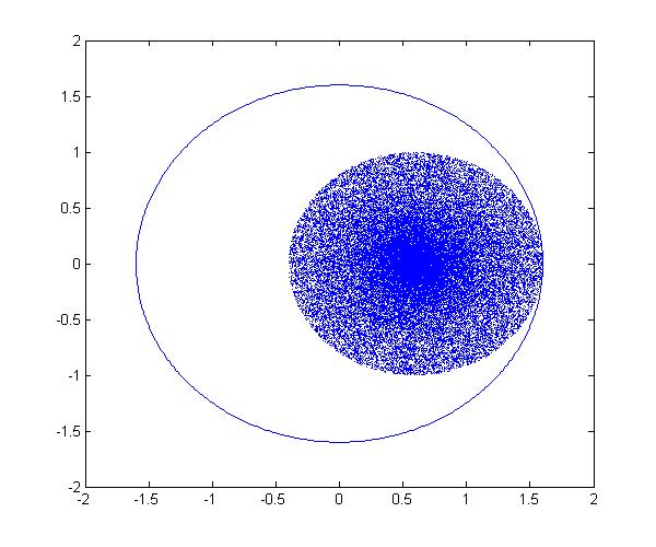
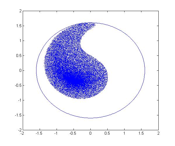
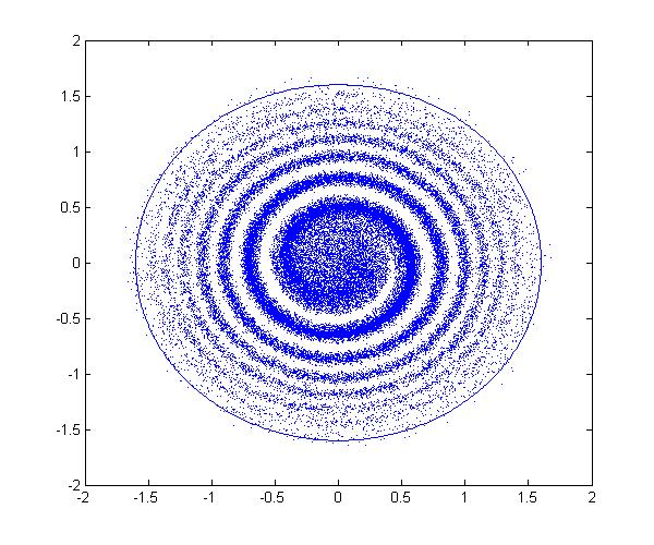
6 Filamentation Filamentation Filamentation Filamentation

7 Filamentation Blow-up from steering error Residual transverse oscillations lead to an effective emittance blowup through filamentation: Injection oscillation Reference closed orbit Consider a collection of particles with max. amplitudes A The beam can be injected with an error in angle and position. For an injection error Δa, in units of σ = (βε), the mis-injected beam is offset in normalised phase space by an amplitude L = Δa ε Any given point on the matched ellipse is randomised over all phases after filamentation due to the steering error For a general particle distribution, where A i denotes amplitude in normalised phase of particle i: ε matched = A i After filamentation: ε diluted = ε matched + L See appendix for derivation / Matched particles A Effect of steering error on a given particle L θ Blow-up from steering error Blow-up from steering error Consider a collection of particles with max. amplitudes A The beam can be injected with an error in angle and position. For an injection error Δa, in units of σ = (βε), the mis-injected beam is offset in normalised phase space by an amplitude L = Δa ε Matched particles A L Misinjected beam A numerical example. Consider an offset Δa = 0.5σ for injected beam: ε diluted = ε matched + L " % = ε matched $ + Δa ' # & = ε matched [.5] For nominal LHC beam: ε L = Δa ε matched 0.5 ε Misinjected beam allowed growth through LHC cycle ~0 % Matched Beam
8 Multi-turn injection For hadrons the beam density at injection can be limited either by space charge effects or by the injector capacity If we cannot increase charge density, we can sometimes fill the horizontal phase space to increase overall injected intensity. Multi-turn injection for hadrons Example: CERN PSB injection, high intensity beams, fractional tune Q h 0.5 Beam rotates π/ per turn in phase space Turn## On#each#turn#inject#a#new# batch#and#reduce#the# bump#amplitude# If the acceptance of the receiving machine is larger than the delivered beam emittance we can accumulate intensity Septum# Multi-turn injection for hadrons Multi-turn injection for hadrons Injected beam (usually from a linac) Septum magnet Example: CERN PSB injection, high intensity beams, fractional tune Q h 0.5 Beam rotates π/ per turn in phase space Turn## Varying amplitude bump Circulating beam Programmable closed orbit bump No kicker but fast programmable bumpers Bump amplitude decreases and a new batch injected turn-by-turn Phase-space painting Septum#
9 Multi-turn injection for hadrons Example: CERN PSB injection, high intensity beams, fractional tune Q h 0.5 Beam rotates π/ per turn in phase space Turn#3# Multi-turn injection for hadrons Example: CERN PSB injection, high intensity beams, fractional tune Q h 0.5 Beam rotates π/ per turn in phase space Turn#9# Septum# Septum# Multi-turn injection for hadrons Multi-turn injection for hadrons Example: CERN PSB injection, high intensity beams, fractional tune Q h 0.5 Beam rotates π/ per turn in phase space Turn#4# Turn#5# Phase space has been painted Septum# In reality, filamentation (often space-charge driven) occurs to produce a quasiuniform beam
10 Charge exchange H- injection Charge exchange H- injection Multi-turn injection is essential to accumulate high intensity Disadvantages inherent in using an injection septum: Width of several mm reduces aperture Beam losses from circulating beam hitting septum: typically % for the CERN PSB injection at 50 MeV Limits number of injected turns to 0-0 Charge-exchange injection provides elegant alternative Possible to cheat Liouville s theorem, which says that emittance is conserved. Convert H - to p + using a thin stripping foil, allowing injection into the same phase space area Circulating p + Displace orbit End of injection process with painting Stripping foil H 0 # Circulating p + Injection chicane dipoles Charge exchange H- injection Charge exchange H- injection Start of injection process Stripping foil H 0 # Paint uniform transverse phase space density by modifying closed orbit bump and steering injected beam Foil thickness calculated to double-strip most ions ( 99%) 50 MeV 50 µg.cm MeV 00 µg.cm - ( µm of C!) Circulating p + Circulating p + Carbon foils generally used very fragile Injection chicane reduced or switched off after injection, to avoid excessive foil heating and beam blow-up Longitudinal phase space can also be painted turn-by-turn: Variation of the injected beam energy turn-by-turn (linac voltage scaled) Injection chicane dipoles Chopper system in linac to match length of injected batch to bucket

11 H- injection - painting x #vs#x# y #vs#y# y#vs#x# Time Injected beam Betatron lepton injection Septum magnet Circulating beam Note injection into same phase space area as circulating beam Closed orbit bumpers or kickers 00 turns Beam is injected with an angle with respect to the closed orbit Injected beam performs damped betatron oscillations about the closed orbit Lepton injection Betatron lepton injection Single-turn injection can be used as for hadrons; however, lepton motion is strongly damped (different with respect to proton or ion injection). Injected bunch performs damped betatron oscillations Synchrotron radiation see Electron Beam Dynamics lectures by L. Rivkin Can use transverse or longitudinal damping: Transverse - Betatron accumulation Longitudinal - Synchrotron accumulation In LEP at 0 GeV, the damping time was about turns (0.6 seconds)
12 Synchrotron lepton injection Synchrotron lepton injection in LEP Injected beam p = p 0 + Δp Septum magnet Inject an off-momentum beam p = p 0 Bumped circulating beam x s# Closed orbit bumpers or kickers x s = D x Δp/p 0 Beam injected parallel to circulating beam, onto dispersion orbit of a particle having the same momentum offset Δp/p Injected beam makes damped synchrotron oscillations at Q s but does not perform betatron oscillations Synchrotron injection in LEP gave improved background for LEP experiments due to small orbit offsets in zero dispersion straight sections Synchrotron lepton injection Double batch injection possible. RF#bucket# Injec*on##(turn#N#+#Q s /)# Stored#beam# Injec*on##(turn#N)# E Injection - summary Several different techniques using kickers, septa and bumpers: Single-turn injection for hadrons Boxcar stacking: transfer between machines in accelerator chain Angle / position errors injection oscillations Uncorrected errors filamentation emittance increase Multi-turn injection for hadrons Phase space painting to increase intensity H- injection allows injection into same phase space area Lepton injection: take advantage of damping Less concerned about injection precision and matching Φ Longitudinal damping time in LEP was ~3 000 turns (x faster than transverse)
13 Extraction Fast single turn extraction Different extraction techniques exist, depending on requirements Fast extraction: turn Non-resonant multi-turn extraction: few turns Resonant low-loss multi-turn extraction: few turns Resonant multi-turn extraction: many thousands of turns Usually higher energy than injection stronger elements ( B.dl) At high energies many kicker and septum modules may be required p+ For transfer of beams between accelerators in an injector chain For secondary particle production (e.g. neutrinos, radioactive beams) Septum deflection may be in the other plane to the kicker deflection Lambertson septum to be discussed tomorrow Losses from transverse scraping or from particles in extraction gap: Fast extraction from SPS to CNGS: Particles in SPS extraction kicker rise- and fall-time gaps.e+. k/ko To reduce kicker and septum strength, beam can be moved near to septum by closed orbit bump.e E Intensity [0^9 p/5ns] Kicker strength 0..E time us 0.0 Extracted beam Fast single turn extraction Entire beam kicked into septum gap and extracted over a single turn intensity Septum magnet Multi-turn extraction Some filling schemes require a beam to be injected in several turns to a larger machine And very commonly Fixed Target physics experiments and medical accelerators often need a quasi-continuous flux of particles kicker field t Multi-turn extraction Non-resonant multi-turn ejection (few turns) for filling Circulating beam e.g. PS to SPS at CERN for high intensity proton beams (> protons) Resonant extraction (ms to hours) for experiments F-quad Closed orbit bumpers D-quad Kicker magnet Bumpers move circulating beam close to septum to reduce kicker strength Kicker deflects the entire beam into the septum in a single turn Most efficient (lowest deflection angles required) for π/ phase advance between kicker and septum
14 Non-resonant multi-turn extraction Non-resonant multi-turn extraction Extracted beam Beam bumped to septum; part of beam shaved off each turn Magnetic septum CERN PS to SPS: 5-turn continuous transfer st turn Q h #=#0.5# septum# Electrostatic septum Bumped circulating beam Fast closed orbit bumpers Bump vs. turn Fast bumper deflects the whole beam onto the septum Beam extracted in a few turns, with the machine tune rotating the beam Intrinsically a high-loss process: thin septum essential Often combine thin electrostatic septa with magnetic septa Non-resonant multi-turn extraction Example system: CERN PS to SPS Fixed-Target continuous transfer. Accelerate beam in PS to 4 GeV/c Empty PS machine (. µs long) in 5 turns into SPS Do it again Fill SPS machine (3 µs long) beam Quasi-continuous beam in SPS ( x µs gaps) Total intensity per PS extraction p+ Total intensity in SPS p+ Non-resonant multi-turn extraction CERN PS to SPS: 5-turn continuous transfer nd turn Q h #=#0.5# septum# To the SPS Bump vs. turn Extracted beam The PS
15 Non-resonant multi-turn extraction Non-resonant multi-turn extraction CERN PS to SPS: 5-turn continuous transfer 3 rd turn Q h #=#0.5# septum# CERN PS to SPS: 5-turn continuous transfer 5 th turn Q h #=#0.5# Bump vs. turn Bump vs. turn Non-resonant multi-turn extraction CERN PS to SPS: 5-turn continuous transfer 4 th turn Q h #=#0.5# septum# 5 4 Non-resonant multi-turn extraction CERN PS to SPS: 5-turn continuous transfer Losses impose thin (ES) septum a second magnetic septum is needed Still about 5 % of beam lost in PS-SPS CT Difficult to get equal intensities per turn Different trajectories for each turn Different emittances for each turn I Bump vs. turn
16 Resonant low-loss multi-turn extraction Adiabatic capture of beam in stable islands Use non-linear fields (sextupoles and octupoles) to create islands of stability in phase space A slow (adiabatic) tune variation to cross a resonance and to drive particles into the islands (capture) with the help of transverse excitation (using damper) Variation of field strengths to separate the islands in phase space Extracted beam Resonant multi-turn extraction Non-linear fields excite resonances that drive the beam slowly across the septum Magnetic septum Electrostatic septum Several big advantages: Losses reduced significantly (no particles at the septum in transverse plane) Phase space matching improved with respect to existing non-resonant multi-turn extraction - beamlets have similar emittance and optical parameters Bumped circulating beam - particles moved across septum by resonance Closed orbit bumpers Slow bumpers move the beam near the septum Tune adjusted close to n th order betatron resonance Multipole magnets excited to define stable area in phase space, size depends on ΔQ = Q - Q r Resonant low-loss multi-turn extraction a. Unperturbed beam b. Increasing non-linear fields Resonant multi-turn extraction 3 rd order resonances see lectures by Y. Papaphilippou Sextupole fields distort the circular normalised phase space particle trajectories. Stable area defined, delimited by unstable Fixed Points. Q h = 0.5 Courtesy M. Giovannozzi: MTE Design Report, CERN-006-0, 006 Septum wire c. Beam captured in stable islands d. Islands separated and beam bumped across septum extracted in 5 turns Bump vs. turn / R fp ΔQ k Sextupole magnets arranged to produce suitable phase space orientation of the stable triangle at thin electrostatic septum Stable area can be reduced by Increasing the sextupole strength, or Fixing the sextupole strength and scanning the machine tune Q h (and therefore the resonance) through the tune spread of the beam Large tune spread created with RF gymnastics (large momentum spread) and large chromaticity R fp
17 Third-order resonant extraction Third-order resonant extraction Septum wire Septum wire Particles distributed on emittance contours ΔQ large no phase space distortion ΔQ small enough that largest amplitude particle trajectories are unstable Unstable particles follow separatrix branches as they increase in amplitude Third-order resonant extraction Third-order resonant extraction Septum wire Septum wire Sextupole magnets produce a triangular stable area in phase space ΔQ decreasing phase space distortion for largest amplitudes As the stable area shrinks, the circulating beam intensity drops since particles are being continuously extracted


18 Third-order resonant extraction Third-order resonant extraction On resonance, sextupole kicks add-up driving particles over septum Distance travelled in these final three turns is termed the spiral step, ΔX ES Extraction bump trimmed in the machine to adjust the spiral step X ES θ Extracted beam ΔX ES ΔX ES k X ES cosθ momentum spread, tune Δp p ΔQ A: Ch Spectrum Range: 0 dbm Sec -30 dbm RF gymn. Septum wire As the stable area shrinks, the circulating beam intensity drops since particles are being continuously extracted RF gymnastics before extraction: small Δp Δϕ = π Δϕ = -π rotation: large Δp time Spill = 4.8 s -30 dbm Sec Sec Center: GHz Span: 0 khz RBW: 00 Hz TimeLen: msec RF off Schottky measurement during spill, courtesy of T. Bohl Third-order resonant extraction Slow extraction channel: SPS extraction TPST magnetic QFA electrostatic septum (ES) septum (MST) QDA bumper mask QFA magnetic septum (MSE) To TT0 and NA ES extracted beam circulating beam Septum wire As ΔQ approaches zero, the particles with very small amplitude are extracted
 at the level of a few ppm!")
19 Slow extracted spill quality The slow-extraction is a resonant process and it amplifies the smallest imperfections in the machine: - e.g. spill intensity variations can be explained by ripples in the current of the quads (mains: n x 50 Hz) at the level of a few ppm! - Injection of n x 50 Hz signals in counter-phase on dedicated quads can be used to compensate Resonant extraction separatrices Reducing ΔQ with main machine quadrupoles can be augmented with a servo quadrupole, which can modulate ΔQ in a servo loop, acting on a measurement of the spill intensity 0 Hz 50 Hz 3 rd order resonant extraction nd order resonant extraction A recent example of a spill at SPS to the North Area with large n x 50 Hz components and another noise source at 0 Hz Amplitude growth for nd order resonance much faster than 3 rd shorter spills ( milliseconds vs. seconds) Used where intense pulses are required on target e.g. neutrino production Second-order resonant extraction Extraction - summary An extraction can also be made over a few hundred turns nd and 4 th order resonances Octupole fields distort the regular phase space particle trajectories Stable area defined, delimited by two unstable Fixed Points Beam tune brought across a nd order resonance (Q 0.5) Particle amplitudes quickly grow and beam is extracted in a few hundred turns Several different techniques: Single-turn fast extraction: for Boxcar stacking (transfer between machines in accelerator chain), beam abort Non-resonant multi-turn extraction slice beam into equal parts for transfer between machine over a few turns. Resonant low-loss multi-turn extraction create stable islands in phase space: slice off over a few turns. Resonant multi-turn extraction create stable area in phase space slowly drive particles into resonance long spill over many thousand turns. Thank you for your attention
20 Appendix Blow-up from steering error So we plug in the new coordinates: A error Taking the average over distribution: A error = X error + X ' error = (X 0 + L cosθ) + (X ' 0 + Lsinθ) = X 0 + X ' 0 + L(X 0 cosθ + X ' 0 sinθ)+ L = A 0 = ε matched + L Giving the diluted emittance as: 0 + L( X 0 cosθ + X ' 0 sinθ )+ L ε diluted = ε matched + L " % = ε matched $ + Δa ' # & 0 cos θ + sin θ = Matched particles A L = Δa ε matched Effect of steering error on a given particle L θ Blow-up from steering error The new particle coordinates in normalised phase space are: X error = X 0 + L cosθ X ' error = X ' 0 + Lsinθ For a general particle distribution, where A i denotes amplitude in normalised phase of particle i: Matched particles L = Δa ε matched Misinjected beam A i = X 0,i + X ' 0,i A 0 The emittance of the distribution is: θ L ε matched = A i /
NOVEL METHOD FOR MULTI-TURN EXTRACTION: TRAPPING CHARGED PARTICLES IN ISLANDS OF PHASE SPACE
 EUROPEAN ORGANIZATION FOR NUCLEAR RESEARCH CERN - PS DIVISION CERN/PS 200-05 (AE) NOVEL METHOD FOR MULTI-TURN EXTRACTION: TRAPPING CHARGED PARTICLES IN ISLANDS OF PHASE SPACE R. Cappi and M. Giovannozzi
Measurement and Compensation of Betatron Resonances at the CERN PS Booster Synchrotron
 Measurement and Compensation of Betatron Resonances at the CERN PS Booster Synchrotron Urschütz Peter (AB/ABP) CLIC meeting, 29.10.2004 1 Overview General Information on the PS Booster Synchrotron Motivation
Transverse dynamics Selected topics. Erik Adli, University of Oslo, August 2016, v2.21
 Transverse dynamics Selected topics Erik Adli, University of Oslo, August 2016, Erik.Adli@fys.uio.no, v2.21 Dispersion So far, we have studied particles with reference momentum p = p 0. A dipole field
LIS section meeting. PS2 design status. Y. Papaphilippou. April 30 th, 2007
 LIS section meeting PS2 design status Y. Papaphilippou April 30 th, 2007 Upgrade of the injector chain (R. Garoby, PAF) Proton flux / Beam power 50 MeV 160 MeV Linac2 Linac4 1.4 GeV ~ 5 GeV PSB SPL RCPSB
Beam Dynamics. D. Brandt, CERN. CAS Bruges June 2009 Beam Dynamics D. Brandt 1
 Beam Dynamics D. Brandt, CERN D. Brandt 1 Some generalities D. Brandt 2 Units: the electronvolt (ev) The electronvolt (ev)) is the energy gained by an electron travelling, in vacuum, between two points
Longitudinal Top-up Injection for Small Aperture Storage Rings
 Longitudinal Top-up Injection for Small Aperture Storage Rings M. Aiba, M. Böge, Á. Saá Hernández, F. Marcellini and A. Streun Paul Scherrer Institut Introduction Lower and lower horizontal emittances
Beam Diagnostics. Measuring Complex Accelerator Parameters Uli Raich CERN BE-BI
 Beam Diagnostics Measuring Complex Accelerator Parameters Uli Raich CERN BE-BI CERN Accelerator School Prague, 2014 Contents Some examples of measurements done with the instruments explained during the
Longitudinal Dynamics
 Longitudinal Dynamics F = e (E + v x B) CAS Bruges 16-25 June 2009 Beam Dynamics D. Brandt 1 Acceleration The accelerator has to provide kinetic energy to the charged particles, i.e. increase the momentum
D. Brandt, CERN. CAS Frascati 2008 Accelerators for Newcomers D. Brandt 1
 Accelerators for Newcomers D. Brandt, CERN D. Brandt 1 Why this Introduction? During this school, you will learn about beam dynamics in a rigorous way but some of you are completely new to the field of
Beam Diagnostics Lecture 3. Measuring Complex Accelerator Parameters Uli Raich CERN AB-BI
 Beam Diagnostics Lecture 3 Measuring Complex Accelerator Parameters Uli Raich CERN AB-BI Contents of lecture 3 Some examples of measurements done with the instruments explained during the last 2 lectures
The optimization for the conceptual design of a 300 MeV proton synchrotron *
 The optimization for the conceptual design of a 300 MeV proton synchrotron * Yu-Wen An ( 安宇文 ) 1,2), Hong-Fei Ji ( 纪红飞 ) 1,2), Sheng Wang ( 王生 ) 1,2), Liang-Sheng Huang ( 黄良生 ) 1,2;1) 1 Institute of High
MULTITURN EXTRACTION BASED ON TRAPPING IN STABLE ISLANDS AT CERN PS: RECENT MEASUREMENT ADVANCES
 MULTITURN EXTRACTION BASED ON TRAPPING IN STABLE ISLANDS AT CERN PS: RECENT MEASUREMENT ADVANCES M. Giovannozzi and R. Cappi, S. Gilardoni, M. Martini, E. Métral, M A. Sakumi, R. Steerenberg, CERN A.-S.
Bernhard Holzer, CERN-LHC
 Bernhard Holzer, CERN-LHC * Bernhard Holzer, CERN CAS Prague 2014 x Liouville: in reasonable storage rings area in phase space is constant. A = π*ε=const x ε beam emittance = woozilycity of the particle
Lattice Design and Performance for PEP-X Light Source
 Lattice Design and Performance for PEP-X Light Source Yuri Nosochkov SLAC National Accelerator Laboratory With contributions by M-H. Wang, Y. Cai, X. Huang, K. Bane 48th ICFA Advanced Beam Dynamics Workshop
TUNE SPREAD STUDIES AT INJECTION ENERGIES FOR THE CERN PROTON SYNCHROTRON BOOSTER
 TUNE SPREAD STUDIES AT INJECTION ENERGIES FOR THE CERN PROTON SYNCHROTRON BOOSTER B. Mikulec, A. Findlay, V. Raginel, G. Rumolo, G. Sterbini, CERN, Geneva, Switzerland Abstract In the near future, a new
!"#$%$!&'()$"('*+,-')'+-$#..+/+,0)&,$%.1&&/$ LONGITUDINAL BEAM DYNAMICS
$('*+,-')'+-$#..+/+,0)&,$%.1&&/$ LONGITUDINAL BEAM DYNAMICS") LONGITUDINAL BEAM DYNAMICS Elias Métral BE Department CERN The present transparencies are inherited from Frank Tecker (CERN-BE), who gave this course last year and who inherited them from Roberto Corsini
LONGITUDINAL BEAM DYNAMICS Elias Métral BE Department CERN The present transparencies are inherited from Frank Tecker (CERN-BE), who gave this course last year and who inherited them from Roberto Corsini
The TESLA Dogbone Damping Ring
 The TESLA Dogbone Damping Ring Winfried Decking for the TESLA Collaboration April 6 th 2004 Outline The Dogbone Issues: Kicker Design Dynamic Aperture Emittance Dilution due to Stray-Fields Collective
50 MeV 1.4 GeV 25GeV 450 GeV 8 TeV. Sources of emittance growth CAS 07 Liverpool. Sept D. Möhl, slide 1
 * 5 KeV 750 KeV 50 MeV 1.4 GeV 5GeV 450 GeV 8 TeV Sources of emittance growth CAS 07 Liverpool. Sept. 007 D. Möhl, slide 1 Sources of Emittance Growth Dieter Möhl Menu Overview Definition of emittance,
Accelerators. There are some accelerators around the world Nearly all are for industrial (20 000) or clinical use (10 000)
 or clinical use (10 000)") Accelerators There are some 30 000 accelerators around the world Nearly all are for industrial (20 000) or clinical use (10 000) Scientific research community (~ 100) Synchrotron light sources Ion beam
Accelerators There are some 30 000 accelerators around the world Nearly all are for industrial (20 000) or clinical use (10 000) Scientific research community (~ 100) Synchrotron light sources Ion beam
PBL SCENARIO ON ACCELERATORS: SUMMARY
 PBL SCENARIO ON ACCELERATORS: SUMMARY Elias Métral Elias.Metral@cern.ch Tel.: 72560 or 164809 CERN accelerators and CERN Control Centre Machine luminosity Transverse beam dynamics + space charge Longitudinal
Injection: Hadron Beams
 Proceedings of the CAS CERN Accelerator School: Beam Injection, Extraction and Transfer, Erice, Italy, 10-19 March 2017, edited by B. Holzer, CERN Yellow Reports: School Proceedings, Vol. 5/2018, CERN-2018-008-SP
Raising intensity of the LHC beam in the SPS - longitudinal plane
 SL-Note-- MD Raising intensity of the LHC beam in the SPS - longitudinal plane Ph. Baudrenghien, T. Bohl, T. Linnecar, E. Shaposhnikova Abstract Different aspects of the LHC type beam capture and acceleration
Operational performance of the CERN injector complex with transversely split beams
 PHYSICAL REVIEW ACCELERATORS AND BEAMS 20, 014001 (2017) Operational performance of the CERN injector complex with transversely split beams S. Abernethy, 1,2 A. Akroh, 2 H. Bartosik, 2 A. Blas, 2 T. Bohl,
Run2 Problem List (Bold-faced items are those the BP Department can work on) October 4, 2002
 October 4, 2002") Run2 Problem List (Bold-faced items are those the BP Department can work on) October 4, 2002 Linac Booster o 4.5-4.8e12 ppp at 0.5 Hz o Space charge (30% loss in the first 5 ms) o Main magnet field quality
Run2 Problem List (Bold-faced items are those the BP Department can work on) October 4, 2002 Linac Booster o 4.5-4.8e12 ppp at 0.5 Hz o Space charge (30% loss in the first 5 ms) o Main magnet field quality
A Project to convert TLS Booster to hadron accelerator 1. Basic design. 2. The injection systems:
 A Project to convert TLS Booster to hadron accelerator 1. Basic design TLS is made of a 50 MeV electron linac, a booster from 50 MeV to 1.5 GeV, and a storage ring. The TLS storage ring is currently operating
Lattice Design for the Taiwan Photon Source (TPS) at NSRRC
 at NSRRC") Lattice Design for the Taiwan Photon Source (TPS) at NSRRC Chin-Cheng Kuo On behalf of the TPS Lattice Design Team Ambient Ground Motion and Civil Engineering for Low Emittance Electron Storage Ring Workshop
Lattice Design for the Taiwan Photon Source (TPS) at NSRRC Chin-Cheng Kuo On behalf of the TPS Lattice Design Team Ambient Ground Motion and Civil Engineering for Low Emittance Electron Storage Ring Workshop
INJECTION PAINTING AND ASSOCIATED HW FOR 160 MeV PSB H
 Proceedings of HB, Morschach, Switzerland TUOB INJECTION PAINTING AND ASSOCIATED HW FOR 6 MeV PSB H C. Bracco, B. Balhan, J. Borburgh, C. Carli, E. Carlier, R. Chamizo, M. Chanel, T. Fowler, B. Goddard,
COMBINER RING LATTICE
 CTFF3 TECHNICAL NOTE INFN - LNF, Accelerator Division Frascati, April 4, 21 Note: CTFF3-2 COMBINER RING LATTICE C. Biscari 1. Introduction The 3 rd CLIC test facility, CTF3, is foreseen to check the feasibility
Small Synchrotrons. Michael Benedikt. CERN, AB-Department. CAS, Zeegse, 30/05/05 Small Synchrotrons M. Benedikt 1
 Small Synchrotrons Michael Benedikt CERN, AB-Department CAS, Zeegse, 30/05/05 Small Synchrotrons M. Benedikt 1 Contents Introduction Synchrotron linac - cyclotron Main elements of the synchrotron Accelerator
Beam Transfer Lines. Brennan Goddard CERN
 Beam Transfer Lines Distinctions between transfer lines and circular machines Linking machines together Trajectory correction Emittance and mismatch measurement Blow-up from steering errors, optics mismatch
Introduction to particle accelerators
 Introduction to particle accelerators Walter Scandale CERN - AT department Lecce, 17 June 2006 Introductory remarks Particle accelerators are black boxes producing either flux of particles impinging on
1.5-GeV FFAG Accelerator as Injector to the BNL-AGS
 1.5-GeV FFAG Accelerator as Injector to the BNL-AGS Alessandro G. Ruggiero M. Blaskiewicz,, T. Roser, D. Trbojevic,, N. Tsoupas,, W. Zhang Oral Contribution to EPAC 04. July 5-9, 5 2004 Present BNL - AGS
ThomX Machine Advisory Committee. (LAL Orsay, March ) Ring Beam Dynamics
 Ring Beam Dynamics") ThomX Machine Advisory Committee (LAL Orsay, March 20-21 2017) Ring Beam Dynamics A. Loulergue, M. Biagini, C. Bruni, I. Chaikovska I. Debrot, N. Delerue, A. Gamelin, H. Guler, J. Zang Programme Investissements
ThomX Machine Advisory Committee (LAL Orsay, March 20-21 2017) Ring Beam Dynamics A. Loulergue, M. Biagini, C. Bruni, I. Chaikovska I. Debrot, N. Delerue, A. Gamelin, H. Guler, J. Zang Programme Investissements
BEAM TESTS OF THE LHC TRANSVERSE FEEDBACK SYSTEM
 JINR BEAM TESTS OF THE LHC TRANSVERSE FEEDBACK SYSTEM W.Höfle, G.Kotzian, E.Montesinos, M.Schokker, D.Valuch (CERN) V.M. Zhabitsky (JINR) XXII Russian Particle Accelerator Conference 27.9-1.1. 21, Protvino
INTENSITY AND ENERGY LIMITATIONS OF THE CERN PS COMPLEX
 INTENSITY AND ENERGY LIMITATIONS OF THE CERN PS COMPLEX M.Gourber-Pace, CERN, Geneva, Switzerland Abstract In the next few years, the PS complex (Linac2-PS Booster-PS) will accelerate again very intense
S. Guiducci. Table 1 PADME beam from Linac. Energy (MeV) 550. Number of positrons per pulse Pulse length (ns)
 550. Number of positrons per pulse Pulse length (ns)") K K DA ΦNE TECHNICAL NOTE INFN - LNF, Accelerator Division Frascati, 11/01/2017 Note: G-73 PRELIMINARY CONSIDERATIONS ON THE USE OF DAΦNE POSITRON RING AS A PULSE STRETCHER FOR THE DAΦNE LINAC S. Guiducci
K K DA ΦNE TECHNICAL NOTE INFN - LNF, Accelerator Division Frascati, 11/01/2017 Note: G-73 PRELIMINARY CONSIDERATIONS ON THE USE OF DAΦNE POSITRON RING AS A PULSE STRETCHER FOR THE DAΦNE LINAC S. Guiducci
Operational Experience with HERA
 PAC 07, Albuquerque, NM, June 27, 2007 Operational Experience with HERA Joachim Keil / DESY On behalf of the HERA team Contents Introduction HERA II Luminosity Production Experiences with HERA Persistent
Introduction to Collider Physics
 Introduction to Collider Physics William Barletta United States Particle Accelerator School Dept. of Physics, MIT The Very Big Picture Accelerators Figure of Merit 1: Accelerator energy ==> energy frontier
Particle physics experiments
 Particle physics experiments Particle physics experiments: collide particles to produce new particles reveal their internal structure and laws of their interactions by observing regularities, measuring
The achievements of the CERN proton antiproton collider
 The achievements of the CERN proton antiproton collider Luigi DiLella Scuola Normale Superiore, Pisa, Italy Motivation of the project The proton antiproton collider UA1 and UA2 detectors Discovery of the
Proposta per l'uso di DAFNE come allungatore d'impulso per il fascio di positroni del Linac
 Proposta per l'uso di DAFNE come allungatore d'impulso per il fascio di positroni del Linac S. Guiducci 29 novembre 2017 11/29/17 1 The PADME experiment at BTF The PADME experiment proposes a search for
CNGS proton beam. Malika Meddahi for SL/BT group CERN
 CNGS proton beam Malika Meddahi for SL/BT group CERN CNGS proton beam Layout of the proton line Beam parameters Extraction channel New magnets Intensity limitations Requirements for beam instrumentation
On-axis injection into small dynamic aperture
 On-axis injection into small dynamic aperture L. Emery Accelerator Systems Division Argonne National Laboratory Future Light Source Workshop 2010 Tuesday March 2nd, 2010 On-Axis (Swap-Out) injection for
ACHIEVABLE SPACE-CHARGE TUNE SHIFT WITH LONG LIFETIME IN THE CERN PS & SPS
 Contributed talk (15 + 5 min, 30 slides) ACHIEVABLE SPACE-CHARGE TUNE SHIFT WITH LONG LIFETIME IN THE CERN PS & SPS Elias Métral Elias Métral, HB2008 workshop, Nashville, Tennessee, USA, August 25-29,
International Scientific Spring 2010, March 1-6, 1. R. Garoby. slhc
 International Scientific Spring 2010, March 1-6, 1 2010 R. Garoby slhc 1. Plans for future LHC injectors 2. Implementation stages 3. Final words R.G. 2 3/10/2009 R.G. 3 3 3/10/2009 Motivation 1. Reliability
Accelerator Physics. Tip World Scientific NEW JERSEY LONDON SINGAPORE BEIJING SHANGHAI HONG KONG TAIPEI BANGALORE. Second Edition. S. Y.
 Accelerator Physics Second Edition S. Y. Lee Department of Physics, Indiana University Tip World Scientific NEW JERSEY LONDON SINGAPORE BEIJING SHANGHAI HONG KONG TAIPEI BANGALORE Contents Preface Preface
The FAIR Accelerator Facility
 The FAIR Accelerator Facility SIS300 existing GSI proton linac SIS18 UNILAC SIS100 HESR pbar target SuperFRS goals: higher intensity (low charge states) higher energy (high charge states) production of
Status of linear collider designs:
 Status of linear collider designs: Main linacs Design overview, principal open issues G. Dugan March 11, 2002 Linear colliders: main linacs The main linac is the heart of the linear collider TESLA, NLC/JLC,
Introduction to Accelerators
 Introduction to Accelerators D. Brandt, CERN CAS Platja d Aro 2006 Introduction to Accelerators D. Brandt 1 Why an Introduction? The time where each accelerator sector was working alone in its corner is
OTHER MEANS TO INCREASE THE SPS 25 ns PERFORMANCE TRANSVERSE PLANE
 OTHER MEANS TO INCREASE THE SPS 25 ns PERFORMANCE TRANSVERSE PLANE H. Bartosik, G. Arduini, A. Blas, C. Bracco, T. Bohl, K. Cornelis, H. Damerau, S. Gilardoni, S. Hancock, B. Goddard, W. Höfle, G. Iadarola,
Physics 610. Adv Particle Physics. April 7, 2014
 Physics 610 Adv Particle Physics April 7, 2014 Accelerators History Two Principles Electrostatic Cockcroft-Walton Van de Graaff and tandem Van de Graaff Transformers Cyclotron Betatron Linear Induction
ILC Beam Dynamics Studies Using PLACET
 ILC Beam Dynamics Studies Using PLACET Andrea Latina (CERN) July 11, 2007 John Adams Institute for Accelerator Science - Oxford (UK) Introduction Simulations Results Conclusions and Outlook PLACET Physical
Putting it all together
 Putting it all together Werner Herr, CERN (Version n.n) http://cern.ch/werner.herr/cas24/lectures/praha review.pdf 01 0 1 00 11 00 11 00 11 000 111 01 0 1 00 11 00 11 00 11 000 111 01 0 1 00 11 00 11 00
The MAX IV Thermionic preinjector
 The MAX IV Thermionic preinjector David Olsson ESLS RF, Lund, 2015-09-30 Injection Requirements I Full-energy injection from the LINAC 1.5 GeV and 3 GeV extraction points. Both storage rings will be operated
Phase Space Study of the Synchrotron Oscillation and Radiation Damping of the Longitudinal and Transverse Oscillations
 ScienceAsia 28 (2002 : 393-400 Phase Space Study of the Synchrotron Oscillation and Radiation Damping of the Longitudinal and Transverse Oscillations Balabhadrapatruni Harita*, Masumi Sugawara, Takehiko
First propositions of a lattice for the future upgrade of SOLEIL. A. Nadji On behalf of the Accelerators and Engineering Division
 First propositions of a lattice for the future upgrade of SOLEIL A. Nadji On behalf of the Accelerators and Engineering Division 1 SOLEIL : A 3 rd generation synchrotron light source 29 beamlines operational
HIRFL STATUS AND HIRFL-CSR PROJECT IN LANZHOU
 HIRFL STATUS AND HIRFL-CSR PROJECT IN LANZHOU J. W. Xia, Y. F. Wang, Y. N. Rao, Y. J. Yuan, M. T. Song, W. Z. Zhang, P. Yuan, W. Gu, X. T. Yang, X. D. Yang, S. L. Liu, H.W.Zhao, J.Y.Tang, W. L. Zhan, B.
Physics 736. Experimental Methods in Nuclear-, Particle-, and Astrophysics. - Accelerator Techniques: Introduction and History -
 Physics 736 Experimental Methods in Nuclear-, Particle-, and Astrophysics - Accelerator Techniques: Introduction and History - Karsten Heeger heeger@wisc.edu Homework #8 Karsten Heeger, Univ. of Wisconsin
Multiturn Extraction Based on Trapping in Stable Islands
 Multiturn Extraction Based on Trapping in Stable Islands R. Cappi, S. Gilardoni, M. Giovannozzi, M. Martini, E. Métral, J. Morel, P. Scaramuzzi, R. Steerenberg, CERN, Geneva, Switzerland A.-S. Müller FZK-ISS-ANKA,
Emittance preservation in TESLA
 Emittance preservation in TESLA R.Brinkmann Deutsches Elektronen-Synchrotron DESY,Hamburg, Germany V.Tsakanov Yerevan Physics Institute/CANDLE, Yerevan, Armenia The main approaches to the emittance preservation
Low energy electron storage ring with tunable compaction factor
 REVIEW OF SCIENTIFIC INSTRUMENTS 78, 075107 2007 Low energy electron storage ring with tunable compaction factor S. Y. Lee, J. Kolski, Z. Liu, X. Pang, C. Park, W. Tam, and F. Wang Department of Physics,
Status of the ESR And Future Options
 Status of the ESR And Future Options M. Steck for the Storage Ring Division (C. Dimopoulou, A. Dolinskii, S. Litvinov, F. Nolden, P. Petri, U. Popp, I. Schurig) Outline 1) New Old ESR 2) Slow (Resonant)
Practical Lattice Design
 Practical Lattice Design Dario Pellegrini (CERN) dario.pellegrini@cern.ch USPAS January, 15-19, 2018 1/17 D. Pellegrini - Practical Lattice Design Lecture 5. Low Beta Insertions 2/17 D. Pellegrini - Practical
ULTIMATE LHC BEAM. G. Arduini, CERN, Geneva, Switzerland
 Abstract The present status of the nominal LHC beam in the LHC injector complex and the limitations towards the achievement of the ultimate brightness are outlined. ULTIMATE LHC BEAM G. Arduini, CERN,
Non-linear dynamics Yannis PAPAPHILIPPOU CERN
 Non-linear dynamics Yannis PAPAPHILIPPOU CERN United States Particle Accelerator School, University of California - Santa-Cruz, Santa Rosa, CA 14 th 18 th January 2008 1 Summary Driven oscillators and
Tools of Particle Physics I Accelerators
 Tools of Particle Physics I Accelerators W.S. Graves July, 2011 MIT W.S. Graves July, 2011 1.Introduction to Accelerator Physics 2.Three Big Machines Large Hadron Collider (LHC) International Linear Collider
ELECTRON COOLING OF PB54+ IONS IN LEIR
 ELECTRON COOLING OF PB+ IONS IN LEIR G. Tranquille, CERN, Geneva, Switzerland Abstract Electron cooling is central in the preparation of dense bunches of lead beams for the LHC. Ion beam pulses from the
Accelerator Physics. Accelerator Development
 Accelerator Physics The Taiwan Light Source (TLS) is the first large accelerator project in Taiwan. The goal was to build a high performance accelerator which provides a powerful and versatile light source
Proposal to convert TLS Booster for hadron accelerator
 Proposal to convert TLS Booster for hadron accelerator S.Y. Lee -- Department of Physics IU, Bloomington, IN -- NSRRC Basic design TLS is made of a 50 MeV electron linac, a booster from 50 MeV to 1.5 GeV,
Injection and extraction magnets: septa
 Injection and extraction magnets: septa M.J. Barnes, J. Borburgh, B. Goddard, M. Hourican CERN, Geneva, Switzerland Abstract An accelerator has limited dynamic range: a chain of accelerators is required
Diagnostics at the MAX IV 3 GeV storage ring during commissioning. PPT-mall 2. Åke Andersson On behalf of the MAX IV team
 Diagnostics at the MAX IV 3 GeV storage ring during commissioning PPT-mall 2 Åke Andersson On behalf of the MAX IV team IBIC Med 2016, linje Barcelona Outline MAX IV facility overview Linac injector mode
ELECTRON DYNAMICS WITH SYNCHROTRON RADIATION
 ELECTRON DYNAMICS WITH SYNCHROTRON RADIATION Lenny Rivkin Ecole Polythechnique Federale de Lausanne (EPFL) and Paul Scherrer Institute (PSI), Switzerland CERN Accelerator School: Introduction to Accelerator
The CIS project and the design of other low energy proton synchrotrons
 The CIS project and the design of other low energy proton synchrotrons 1. Introduction 2. The CIS project 3. Possible CMS 4. Conclusion S.Y. Lee IU Ref. X. Kang, Ph.D. thesis, Indiana University (1998).
Conceptual design of an accumulator ring for the Diamond II upgrade
 Journal of Physics: Conference Series PAPER OPEN ACCESS Conceptual design of an accumulator ring for the Diamond II upgrade To cite this article: I P S Martin and R Bartolini 218 J. Phys.: Conf. Ser. 167
accelerator physics and ion optics summary longitudinal optics
 accelerator physics and ion optics summary longitudinal optics Sytze Brandenburg sb/accphys003_5/1 feedback energy difference acceleration phase stability when accelerating on slope of sine low energy:
SPACE CHARGE EXPERIMENTS AND BENCHMARKING IN THE PS
 SPACE CHARGE EXPERIMENTS AND BENCHMARKING IN THE PS E. Métral Crossing the integer or half-integer resonance Montague resonance Static & Dynamic Benchmarking of the simulation codes Space charge driven
Status of Optics Design
 17th B2GM, February 5, 2014 Status of Optics Design Y. Ohnishi /KEK 17th B2GM KEK, February 5, 2014 Contents! Lattice parameters! Dynamic aperture under influence of beam-beam effect! Lattice preparation
MISMATCH BETWEEN THE PSB AND CPS DUE TO THE PRESENT VERTICAL RECOMBINATION SCHEME
 Particle Accelerators, 1997, Vol. 58, pp. 201-207 Reprints available directly from the publisher Photocopying permitted by license only 1997 OPA (Overseas Publishers Association) Amsterdam B.V. Published
Statusreport. Status of the GSI accelerators for FRS operation. Jens Stadlmann (FAIR Synchrotrons)
") Statusreport Status of the GSI accelerators for FRS operation Jens Stadlmann (FAIR Synchrotrons) Overview Intensities reached and "candidates" for experiments. Uranium? Upgrade program New developments:
Statusreport Status of the GSI accelerators for FRS operation Jens Stadlmann (FAIR Synchrotrons) Overview Intensities reached and "candidates" for experiments. Uranium? Upgrade program New developments:
PULSE-TO-PULSE TRANSVERSE BEAM EMITTANCE CONTROLLING FOR MLF AND MR IN THE 3-GeV RCS OF J-PARC
 THO3AB3 Proceedings of HB, East-Lansing, MI, USA PULSE-TO-PULSE TRANSVERSE BEAM EMITTANCE CONTROLLING FOR MLF AND MR IN THE 3-GeV RCS OF J-PARC P.K. Saha, H. Harada, H. Hotchi and T. Takayanagi J-PARC
3. Particle accelerators
 3. Particle accelerators 3.1 Relativistic particles 3.2 Electrostatic accelerators 3.3 Ring accelerators Betatron // Cyclotron // Synchrotron 3.4 Linear accelerators 3.5 Collider Van-de-Graaf accelerator
Plans for ions in the injector complex D.Manglunki with the help of I-LHC and LIU-PT teams
 Plans for ions in the injector complex D.Manglunki with the help of I-LHC and LIU-PT teams Special acknowledgements to T.Bohl, C.Carli, E.Carlier, H.Damerau, L.Ducimetière, R.Garoby, S.Gilardoni, S.Hancock,
accelerator physics and ion optics summary longitudinal optics
 accelerator physics and ion optics summary longitudinal optics Sytze Brandenburg sb/accphys007_5/1 coupling energy difference acceleration phase stability when accelerating on slope of sine low energy:
Short Introduction to CLIC and CTF3, Technologies for Future Linear Colliders
 Short Introduction to CLIC and CTF3, Technologies for Future Linear Colliders Explanation of the Basic Principles and Goals Visit to the CTF3 Installation Roger Ruber Collider History p p hadron collider
Update on Optics Modeling for the ATF Damping Ring at KEK Studies for low vertical emittance
 Update on Optics Modeling for the ATF Damping Ring at KEK Studies for low vertical emittance 2009.05.08. K. Kubo, S. Kuroda, T. Okugi (KEK) M.D. Woodley (SLAC), A. Wolski, K. Panagiotidis (U. Liverpool
Linac JUAS lecture summary
 Linac JUAS lecture summary Part1: Introduction to Linacs Linac is the acronym for Linear accelerator, a device where charged particles acquire energy moving on a linear path. There are more than 20 000
6 Bunch Compressor and Transfer to Main Linac
 II-159 6 Bunch Compressor and Transfer to Main Linac 6.1 Introduction The equilibrium bunch length in the damping ring (DR) is 6 mm, too long by an order of magnitude for optimum collider performance (σ
Low Emittance Machines
 CERN Accelerator School Advanced Accelerator Physics Course Trondheim, Norway, August 2013 Low Emittance Machines Part 1: Beam Dynamics with Synchrotron Radiation Andy Wolski The Cockcroft Institute, and
Injection, extraction and transfer
 Injection, etraction and transfer An accelerator has limited dnamic range. hain of stages needed to reach high energ Periodic re-filling of storage rings, like LH Eternal eperiments, like NG &(5&RPOH[
Studies of trapped modes in the new extraction septum of the CERN Proton Synchrotron
 Studies of trapped modes in the new extraction septum of the CERN Proton Synchrotron Serena Persichelli CERN Impedance and collective effects (BE-ABP-ICE) LIU LHC Injectors Upgrade project Università di
E. Wilson - CERN. Components of a synchrotron. Dipole Bending Magnet. Magnetic rigidity. Bending Magnet. Weak focusing - gutter. Transverse ellipse
 Transverse Dynamics E. Wilson - CERN Components of a synchrotron Dipole Bending Magnet Magnetic rigidity Bending Magnet Weak focusing - gutter Transverse ellipse Fields and force in a quadrupole Strong
FFAG Accelerators. CERN Introductory Accelerator School Prague, September 2014
 FFAG Accelerators CERN Introductory Accelerator School Prague, September 2014 Dr. Suzie Sheehy ASTeC Intense Beams Group STFC Rutherford Appleton Laboratory, UK Many thanks to Dr. S. Machida for his advice
Overview of Acceleration
 Overview of Acceleration R B Palmer, Scott Berg, Steve Kahn (presented by Steve Kahn) Nufact-04 RF Frequency Acc types and System Studies Linacs RLA s FFAG s Injection/Extraction US Study 2a acceleration
III. CesrTA Configuration and Optics for Ultra-Low Emittance David Rice Cornell Laboratory for Accelerator-Based Sciences and Education
 III. CesrTA Configuration and Optics for Ultra-Low Emittance David Rice Cornell Laboratory for Accelerator-Based Sciences and Education Introduction Outline CESR Overview CESR Layout Injector Wigglers
FY04 Luminosity Plan. SAG Meeting September 22, 2003 Dave McGinnis
 FY04 Luminosity Plan SAG Meeting September 22, 2003 Dave McGinnis FY03 Performance Accelerator Issues TEV Pbar Main Injector Reliability Operations Study Strategy Shot Strategy Outline FY04 Luminosity
LHC upgrade based on a high intensity high energy injector chain
 LHC upgrade based on a high intensity high energy injector chain Walter Scandale CERN AT department PAF n. 6 CERN, 15 September 2005 luminosity and energy upgrade Phase 2: steps to reach maximum performance
Accelerators for Beginners and the CERN Complex
 Accelerators for Beginners and the CERN Complex Rende Steerenberg CERN, BE/OP 2 Contents Why Accelerators and Colliders? The CERN Accelerator Complex Cycling the Accelerators & Satisfying Users The Main
Longitudinal dynamics Yannis PAPAPHILIPPOU CERN
 Longitudinal dynamics Yannis PAPAPHILIPPOU CERN United States Particle Accelerator School, University of California - Santa-Cruz, Santa Rosa, CA 14 th 18 th January 2008 1 Outline Methods of acceleration
PBL (Problem-Based Learning) scenario for Accelerator Physics Mats Lindroos and E. Métral (CERN, Switzerland) Lund University, Sweden, March 19-23,
 scenario for Accelerator Physics Mats Lindroos and E. Métral (CERN, Switzerland) Lund University, Sweden, March 19-23,") PBL (Problem-Based Learning) scenario for Accelerator Physics Mats Lindroos and E. Métral (CERN, Switzerland) Lund University, Sweden, March 19-23, 2007 As each working day, since the beginning of the
PBL (Problem-Based Learning) scenario for Accelerator Physics Mats Lindroos and E. Métral (CERN, Switzerland) Lund University, Sweden, March 19-23, 2007 As each working day, since the beginning of the
SLS at the Paul Scherrer Institute (PSI), Villigen, Switzerland
, Villigen, Switzerland") SLS at the Paul Scherrer Institute (PSI), Villigen, Switzerland Michael Böge 1 SLS Team at PSI Michael Böge 2 Layout of the SLS Linac, Transferlines Booster Storage Ring (SR) Beamlines and Insertion Devices
SLS at the Paul Scherrer Institute (PSI), Villigen, Switzerland Michael Böge 1 SLS Team at PSI Michael Böge 2 Layout of the SLS Linac, Transferlines Booster Storage Ring (SR) Beamlines and Insertion Devices