ITTC Propeller Benchmark
|
|
|
- Winfred McCarthy
- 5 years ago
- Views:
Transcription

1 ITTC Propeller Benchmark PPTC PPTC, Propeller P VP1304 Report 4488 Potsdam, March April Schiffbau-Versuchsanstalt Potsdam GmbH, Marquardter Chaussee 100, Potsdam Tel , Fax ,

2 PPTC Propeller Page 2 ITTC Propeller Benchmark ITTC Propeller Benchmark PPTC Propeller - VP1304 PPTC, P1727 Client Contractor Schiffbau-Versuchsanstalt Potsdam GmbH Marquardter Chaussee Potsdam Tel Fax Author Dipl.-Ing. R. Grabert Dipl.-Ing. L. Lübke M. Sc. R. Klose Dipl.-Ing U. Barkmann Potsdam, 30/03/ /08/2017 Management Author
3 PPTC Propeller Page 3 Content 1 Introduction Propeller benchmark Paticipants Propeller PPTC - VP PPTC - VP1304, main data PPTC - VP1304, 3D Overview Open water characteristic - thrust model scale Open water characteristic - torque model scale Open water characteristic - efficiency model scale Open water characteristic - thrust Open water characteristic - torque Open water characteristic - efficiency Statistics Tables - model scale Tables Diagrams - Thrust Diagrams - Torque Diagrams - Efficiency Diagrams - Difference CFD and EFD Diagrams - Relative difference CFD and EFD Result EFD Open Water Characteristic EFD - Statistics Result R R01 - Open water characteristic R01 - Differences CFD and EFD R01 - Radial distribution tables R01 - Radial distribution diagrams R01 - Questionaire part I R01 - Questionaire part II Result R R02 - Open water characteristic R02 - Differences CFD and EFD R02 - Radial distribution tables R02 - Radial distribution diagrams R02 - Questionaire part I R02 - Questionaire part II Result R
4 PPTC Propeller Page 4 Content 7.1 R03 - Open water characteristic R03 - Differences CFD and EFD R03 - Radial distribution tables R03 - Radial distribution diagrams R03 - Questionaire part I R03 - Questionaire part II Result R R04 - Open water characteristic R04 - Differences CFD and EFD R04 - Radial distribution tables R04 - Radial distribution diagrams R04 - Questionaire part I Result R R05 - Open water characteristic R05 - Differences CFD and EFD R05 - Radial distribution tables R05 - Radial distribution diagrams R05 - Questionaire part I R05 - Questionaire part II Result R R06 - Open water characteristic R06 - Differences CFD and EFD R06 - Radial distribution tables R06 - Radial distribution diagrams R06 - Questionaire part I R06 - Questionaire part II Result R R07 - Open water characteristic R07 - Differences CFD and EFD R07 - Radial distribution tables R07 - Radial distribution diagrams R07 - Questionaire part I R07 - Questionaire part II Result R R08 - Open water characteristic R08 - Differences CFD and EFD R08 - Radial distribution tables R08 - Radial distribution diagrams R08 - Questionaire part I R08 - Questionaire part II... 70
5 PPTC Propeller Page 5 Content 13 Result R R10 - Open water characteristic R10 - Differences CFD and EFD R10 - Radial distribution tables R10 - Radial distribution diagrams R10 - Questionaire part I R10 - Questionaire part II Result R R11 - Open water characteristic R11 - Differences CFD and EFD R11 - Radial distribution tables R11 - Radial distribution diagrams R11 - Questionaire part I R11 - Questionaire part II Result R R12 - Open water characteristic R12 - Differences CFD and EFD R12 - Radial distribution tables R12 - Radial distribution diagrams R12 - Questionaire part I R12 - Questionaire part II Result R R14 - Open water characteristic R14 - Differences CFD and EFD R14 - Radial distribution tables R14 - Radial distribution diagrams R14 - Questionaire part I R14 - Questionaire part II Result R R15 - Open water characteristic R15 - Differences CFD and EFD R15 - Radial distribution tables R15 - Radial distribution diagrams R15 - Questionaire part I R15 - Questionaire part II Result R R16 - Open water characteristic R16 - Differences CFD and EFD R16 - Radial distribution tables R16 - Radial distribution diagrams R16 - Questionaire part I...105
6 PPTC Propeller Page 6 1 Introduction Propeller benchmark 1 The current ITTC scaling method for propellers is well proven and in use by the majority of the institutions. Nevertheless, problems with applying this method for unconventional propellers like Kappel or CLT propellers occurred and a need to update the procedure has arisen. Therefore the propulsion committee of the 27 th ITTC conference has been asked to initiate a benchmark test for CFD calculations, with the intention to investigate the capabilities of CFD to predict scale effects on the propeller performance. Two different types of propellers had to be investigated, a conventional and an unconventional propeller. For this purpose the controllable pitch propeller VP1304 was used to study the scale effects for a conventional propeller. The VP1304 was already published by the SVA Potsdam in the course of the propeller workshop under the acronym PPTC (Potsdam Propeller Test Case) held at the smp 11 conference in Hamburg. During the period of the 27 th ITTC no free geometry of an unconventional propeller was available. Therefore the propulsion committee of the 28 th ITTC conference has continued this work. SVA Potsdam has provided P1727 as an example for an unconventional propeller. It has been designed by SVA Potsdam for the ongoing research project "TIP RAKE - Further development of the prognosis methods for tip rake propellers", funded by the German Federal Ministry for Economic Affairs and Energy. In the course of the ITTC benchmark, both propellers were investigated in and model scale. Excel sheets were provided for the submission of the computational results. The evaluation of the results is anonymous. Despite the comparison of the CFD results with EFD results is not the main topic of this investigation, EFD results are presented, too. Open water tests have been carried out in SVA Potsdam for both propellers. Furthermore the ITTC scaling method was applied to the open water test results and plotted together with the full scale CFD results. These curves shall show the current state. Within this report the results of the conventional propeller are presented. The results of the unconventional propeller can be found in report Table 1 shows all participants in alphabetic order and which propeller has been calculated by each of them. Within the report each result is numbered in chronologic order of incoming. Table 2 lists the main data of both propellers.
7 PPTC Propeller Page 7 1 Introduction 1.2 Paticipants 2 Institute PPTC TRP VP1304 P1727 China Ship Scientific Research Center X X Dalian University of Technology X X Hamburgische Schiffbau-Versuchsanstalt X X Hyundai Maritime Research Institute X X Indian Institute of Technology Madras X Istanbul Technical University X X Japan Marine United Corporation X X Krylov State Research Centre X X Marine Design & Research Institute of China X Pusan National University X Samsung Ship Model Basin X X Schiffbau-Versuchsanstalt Potsdam X X Shanghai Jiao Tong University X X Shanghai Ship and Shipping Research Institute X Ship Design and Research Centre Gdansk X X SSPA Sweden AB X Total results 14 13
8 PPTC Propeller Page 8 1 Introduction 1.3 Propeller 3 PPTC TRP Propeller VP1304 P1727 Scale ratio l [-] Propeller diameter D [mm] Pitch at r /R = 0.70 P 0.7 [mm] Pitch at r /R = 0.75 P 0.75 [mm] Mean pitch P mean [mm] Chord length at r /R = 0.70 C 0.7 [mm] Chord length at r /R = 0.75 C 0.75 [mm] Thickness at r /R = 0.75 t 0.75 [mm] Pitch ratio Mean pitch ratio P 0.7 /D P mean /D [-] [-] Area ratio A E /A 0 [-] Skew ϴ eff [ ] Rake at r /R = 0.70 ε 0.7 [ ] -9 Rake at r /R = 0.75 ε 0.75 [ ] -8.8 Hub diameter ratio d h /D [-] Number of blades Z [-] 5 4 Direction of rotation right-handed right-handed Operation point model full PPTC Propeller VP1304 scale scale ratio Water density Kinematic viscosity of Rate of revolutions λ r n n [kg/m 3 ] [m²/s] [1/s] E E
9 Ø72.46 Ø72.46 PPTC Propeller Page 9 1 Introduction 1.4 PPTC - VP VP1304 x (t max )/ c x (f max )/ c R R % P/D 52% r/r % 52% 60 45% 52% R % % R1 R R Ø18 H7 HUB No. 1 FULL SCALE 5 DIN A - 6 DIAMETER D 3000 mm HUB DIAMETER d h 910 mm CHORD LENGTH c mm MAX. THICKNESS t 0.7max mm r P c t f ε θ r /R P /D c /D t /c f /c θ ε CHORD LENGTH c 0.75max mm [mm] [mm] [mm] [mm] [mm] [mm] [mm] [-] [-] [-] [-] [-] [ ] [ ] MAX. THICKNESS mm MODEL SCALE DIAMETER D 250 mm HUB DIAMETER d h mm CHORD LENGTH c mm MAX. THICKNESS t 0.7max mm CHORD LENGTH c mm MAX. THICKNESS mm DIMENSIONLESS HUB RATIO PITCH RATIO EXP. AREA RATIO SVA A E/A R tip R LE R SS R PS R TE Hub d h/d d hle d hte l LE l TE l h SKEW θ EXT Z 5 [mm] [mm] [mm] [mm] [mm] [-] [mm] [mm] [mm] [mm] [mm] BLADE NUMBER H SCALE DIRECTION OF ROTATION t 0.75max t 0.75max d h/d P 0.7/D λ RIGHT-HANDED
10 1 Introduction 1.5 PPTC - VP1304, main data 5 PPTC Propeller Page 10
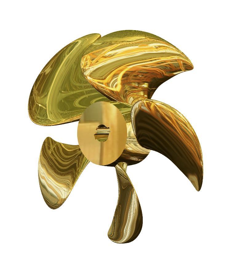


11 1 Introduction 1.6 PPTC - VP1304, 3D 6 PPTC Propeller Page 11
12 K T [-] PPTC Propeller Page 12 2 Overview Open water characteristic - thrust model scale 1 K T [-] model scale D10:D Avarage over J CFD - EFD [-] * [-] ** EFD % R % R % R % R % R % R % R % R % 10 R % R % R % R % R % R % R01 R02 R03 R04 R05 R06 R07 R08 R10 R11 R12 R14 R15 R16 EFD * / ** see at formula page
13 10K Q [-] PPTC Propeller Page 13 2 Overview 2.2 Open water characteristic - torque model scale 2 10K Q [-] model scale E10:E Avarage over J CFD - EFD [-] * [-] ** EFD % R % R % R % R % R % R % R % R % 10 R % R % R % R % R % R % R01 R02 R03 R04 R05 R06 R07 R08 R10 R11 R12 R14 R15 R16 EFD * / ** see at formula page
14 η O [-] PPTC Propeller Page 14 2 Overview 2.3 Open water characteristic - efficiency model scale 3 η O [-] model scale F10:F % Avarage obver J CFD-EFD EFD % R % R % R % R % R % R % R % R % 10 R % R % R % R % R % R % R01 R02 R03 R04 R05 R06 R07 R08 R10 R11 R12 R14 R15 R16 EFD * / ** see at formula page
15 K T [-] PPTC Propeller Page 15 2 Overview 2.4 Open water characteristic - thrust 4 K T [-] H10:H Avarage over J CFD - EFD [-] * [-] ** ITTC' % R % R % R % R % R % R % R % R % 10 R % R % R % R % R % R % R01 R02 R03 R04 R05 R06 R07 R08 R10 R11 R12 R14 R15 R16 EFD * / ** see at formula page
16 10K Q [-] PPTC Propeller Page 16 2 Overview 2.5 Open water characteristic - torque 5 10K Q [-] i10:i Avarage over J CFD - EFD [-] * [-] ** ITTC' % R % R % R % R % R % R % R % R % 10 R % R % R % R % R % R % R01 R02 R03 R04 R05 R06 R07 R08 R10 R11 R12 R14 R15 R16 EFD * / ** see at formula page
17 η O [-] PPTC Propeller Page 17 2 Overview 2.6 Open water characteristic - efficiency 6 η O [-] j10:j Avarage over J CFD - EFD [-] * [-] ** ITTC' % R % R % R % R % R % R % R % R % 10 R % R % R % R % R % R % R01 R02 R03 R04 R05 R06 R07 R08 R10 R11 R12 R14 R15 R16 EFD * / ** see at formula page
18 PPTC Propeller Page 18 3 Statistics Tables - model scale K T [-] model scale 14 $C$12:$C$D$12:$D$E$12:$E$F$12:$F$G$12:$G$49 $I$12:$I$$J$12:$J$ Avarage over J CFD - EFD [-] * [-] ** Minimum % 1 th Quartile % Median % 3 th Quartile % Maximum % K Q [-] model scale $N$12:$N$O$12:$O$P$12:$P$Q$12:$Q$R$12:$R$49 $T$12:$T$U$12:$U$ Avarage over J CFD - EFD [-] * [-] ** Minimum % 1 th Quartile % Median % 3 th Quartile % Maximum % η O [-] model scale $Y$12:$Y$Z$12:$Z$AA$12:$AB$12: $AC$12:$AC$49 $AE$12: $AF$12:$AF$ Avarage over J CFD - EFD [-] * [-] ** Minimum % 1 th Quartile % Median % 3 th Quartile % Maximum % * / ** see at formula page
19 PPTC Propeller Page 19 3 Statistics 3.2 Tables K T [-] $AJ$12:$$AK$12:$AL$12: $AM$12 $AN$12:$AN$49 $AP$12:$$AQ$12:$AQ$ Avarage over J CFD - EFD [-] * [-] ** Minimum % 1 th Quartile % Median % 3 th Quartile % Maximum % K Q [-] $AU$12:$AV$12:$AW$12 $AX$12:$AY$12:$AY$49 $BA$12: $BB$12:$BB$ Avarage over J CFD - EFD [-] * [-] ** Minimum % 1 th Quartile % Median % 3 th Quartile % Maximum % η O [-] $BF$12:$$BG$12: $BH$12: $BI$12:$$BJ$12:$BJ$49 $BL$12:$$BM$12:$BM$ Avarage over J CFD - EFD [-] * [-] ** Minimum % 1 th Quartile % Median % 3 th Quartile % Maximum % * / ** see at formula page
20 K T [-] 3 Statistics 3.3 Diagrams - Thrust 3 PPTC Propeller Page 20 Open water characteristics statistic description CFD model test results model mo ITTC' extrapolation full ful model mo full ful model 1.00 mo full 1.00 ful model 1.20 mo full 1.20 ful model 1.40 mo full 1.40 ful model Avarage CFD-EFD full Avarage CFD-EFD model Avarage CFD-EFD full Avarage CFD-EFD model full model full 1.00 model 1.00 full 1.20 model 1.20 full 1.40 model 1.40 full * / ** see at formula page
21 10K Q [-] PPTC Propeller Page 21 3 Statistics 3.4 Diagrams - Torque Open water characteristics statistic description CFD model mo model 0.6 test results full ful ITTC'78 0.6extrapolation model mo full ful model 1.00 mo full 1.00 ful model 1.20 mo full 1.20 ful model 1.40 mo full 1.40 ful model Avarage CFD-EFD full Avarage CFD-EFD model Avarage CFD-EFD full Avarage CFD-EFD model full model full 1.00 model 1.00 full 1.20 model 1.20 full 1.40 model 1.40 full * / ** see at formula page
22 η O [-] 3 Statistics 3.5 Diagrams - Efficiency 5 PPTC Propeller Page 22 3Open water 2 characteristics statistic 0.25description 1 CFD model mo model test result full ful ITTC' extrapolation model mo full ful model 1.00 mo full 1.00 ful model 1.20 mo full 1.20 ful model 1.40 mo full 1.40 ful model Avarage CFD-EFD full Avarage CFD-EFD model Avarage CFD-EFD full Avarage CFD-EFD model full model full 1.00 model 1.00 full 1.20 model 1.20 full 1.40 model 1.40 full * / ** see at formula page
23 Mean difference over all J of CFD and EFD values [-] 3 Statistics 3.6 Diagrams - Difference CFD and EFD KT model KT full KQ model KQ full Eta model Eta full KT model -4.7% -6.2% -0.4% -8.2% -1.8% KT full -1.9% -2.8% 0.5% -3.9% -0.8% 10KQ model 0.1% -1.0% 3.8% -2.1% 1.2% 10KQ full 1.4% 0.1% 3.5% -1.8% 2.3% Eta model % -7.0% -1.0% -11.6% -4.4% Eta full -3.9% -4.1% -1.3% -5.5% -3.0% PPTC Propeller Page model scale full scale model scale full scale model scale full scale K T 10K Q η O * / ** see at formula page
24 Relative mean difference over all J of CFD and EFD values 3 Statistics 3.7 Diagrams - Relative difference CFD and EFD 7 20% PPTC Propeller Page 24 15% 10% 5% 0% -5% -10% -15% -20% model scale full scale model scale full scale model scale full scale K T 10K Q η O * / ** see at formula page
25 K T, 10K Q, η O [-] K T, 10K Q, η O [-] PPTC Propeller Page 25 4 Result EFD Open Water Characteristic EFD, model scale EFD,, ITTC'78 J K T 10K Q η O K T 10K Q η O [-] [-] [-] [-] [-] [-] [-] K T Open water characteristics model scale EFD K 10K T Q Open water characteristics EFD, ITTC' K T K T 10K Q η O 10K Q η O η O 10K Q η O
26 K K T, T, 10K Q, Q η, O η O [-] [-] K T, 10K Q, η O [-] PPTC Propeller Page 26 4 Result EFD 4.2 EFD - Statistics EFD, model scale EFD,, ITTC'78 J σ(k T ) σ(10k Q ) σ(η O ) σ(k T ) σ(10k Q ) σ(η O ) [-] [-] [-] [-] [-] [-] [-] Open water characteristics EFD, model scale Open water characteristics EFD,, ITTC' J model scale σ(kt) σ(10kq σ(ηo) model scale σ(kt) σ(10kq σ(ηo) 1.40 [-] EFD, test [-] 15F1023 [-] [-] EFD [-] [-] [-] EFD, test 15F standard deviation (N = ) η O K T 0.30 EFD, model scale EFD, full 10K scale, ITTC'78 Q J σ(kt) σ(10kq σ(ηo) σ(kt) σ(10kq σ(ηo) η [-] [-] [-] [-] [-] [-] [-] O K 10K T Q Open 1.4 water characteristics Open water characteristics model scale EFD, with ITTC'78 method EFD, test 15F EFD, test 15F K T K Q η O K T 10K Q J 0.5 [-] η O
27 K T, 10K Q, η O [-] K T, 10K Q, η O [-] PPTC Propeller Page 27 5 Result R01 model scale 5.1 R01 - Open water characteristic J [-] CFD, model scale CFD, K T 10K Q η O K T 10K Q η O [-] [-] [-] [-] [-] [-] Open water characteristics model scale EFD CFD 1.00 η O 10K Q Open water characteristics 1.40 EFD, ITTC78 CFD 1.20 K T 1.00 η O 10K Q K T
28 K T, 10K Q, η O [-] K T, 10K Q, η O [-] 5 Result R R01 - Differences CFD and EFD PPTC Propeller Page CFD - EFD, model scale CFD - EFD, K T 10K Q η O K T 10K Q η O [-] [-] [-] [-] [-] [-] Differences CFD and EFD modell 41 scale K804 T 10K 083 Q 838 η O Differences CFD and EFD, ITTC'78 K T 10K Q η O
29 5 Result R R01 - Radial distribution tables PPTC Propeller Page 29 model scale K T [-] 10K Q [-] r /R [-] K T [-] 10K Q [-] r /R [-] Differences full and model scale K T [-] 10K Q [-] r /R [-]
30 K T [-] 10K Q [-] K T [-] 10K Q [-] K T [-] 10K Q [-] PPTC Propeller Page 30 5 Result R01 J = 5.4 R01 - Radial distribution diagrams J = J = 1.00 J = 1.20 model scale J = Differences full and model scale
31 PPTC Propeller Page 31 5 Result R R01 - Questionaire part I model scale Solver STAR-CCM+ STAR-CCM+ Computational Domain A1 Domain topology Multiple domains Multiple domains A2 Grid-coupling technique Sliding Sliding Propeller Representation B1 Number of considered blades Complete propeller Complete propeller Computational Grid C1 Type Unstructured Unstructured C2 Local-grid refinement Possible - used here Possible - used here C3 Primary volume elements Polyhedral Polyhedral C4 Primary surface elements Other Other C5 Wall-boundary layer type Prism Layer Prism Layer C7 Number of cells at boundary layer C8 Y + -value at r/r=0.4, 0.7, ,0.88, ,1.24,1.53 C9 Averaged Y + -value C10 Number of cells on blade surface Norm. Dim. the Physical Domain D1 X_upstream/D, X_downstream/D 20,40 20,40 D2 Cross area of domain in prop. plain Numerical Approximation E1 Finite Approximation Scheme (Fluid)FV-NS FV-NS E2 Coordinates Cartesian Cartesian E3 Convection scheme (momentum eq.) 2nd-order centered 2nd-order centered E4 Transient approximation implicit implicit E5 Spatial order of acc. (neglecting BC) 2nd-order 2nd-order E6 Temporal order of accuracy 1st-order 1st-order E7 Time step 0185 sec 0642 sec E8 Equivalent rot. Angle for a time step 1 deg 1deg Turbulence treatment F1 Model name k-omega k-omega F2 Convection scheme (Turb. Eqn.) 2nd-order centered 2nd-order centered Boundary conditions G1 Blade resolved resolved G2 Hub resolved resolved G3 Inlet Fixed Velocity Fixed Velocity G4 Outlet Fixed Pressure Fixed Pressure G5 Outer domain Slip flow Slip flow
32 PPTC Propeller Page 32 5 Result R R01 - Questionaire part II model scale Computational Model H1 Fluid incompressible incompressible H2 Pressure pressure correction pressure correction I Transition Please comment Gamma ReTheta method no Computational Demands J1 Number of processors used J2 Number of timesteps (steady) 0 0 J3 Number of timesteps (transient) J4 Wall-clock time per revolution 5460 sec 5813 sec K Code References STAR-CCM+ V10.04 / Primary surface elements: Polyhedral STAR-CCM+ V10.04 / Primary surface elements: Polyhedral L Comments Add. info. 0 / 0 0 / 0
33 K T, 10K Q, η O [-] K T, 10K Q, η O [-] PPTC Propeller Page 33 6 Result R02 model scale 6.1 R02 - Open water characteristic J [-] CFD, model scale CFD, K T 10K Q η O K T 10K Q η O [-] [-] [-] [-] [-] [-] Open water characteristics model scale EFD CFD 1.00 η O 10K Q Open water characteristics 1.40 EFD, ITTC78 CFD 1.20 K T 1.00 η O 10K Q K T
34 K T, 10K Q, η O [-] K T, 10K Q, η O [-] 6 Result R R02 - Differences CFD and EFD PPTC Propeller Page CFD - EFD, model scale CFD - EFD, K T 10K Q η O K T 10K Q η O [-] [-] [-] [-] [-] [-] Differences CFD and EFD modell 026 scale K342 T 10K Q η O Differences CFD and EFD, ITTC'78 K T 10K Q η O
35 6 Result R R02 - Radial distribution tables PPTC Propeller Page 35 model scale K T [-] 10K Q [-] r /R [-] K T [-] 10K Q [-] r /R [-] Differences full and model scale K T [-] 10K Q [-] r /R [-]
36 K T [-] 10K Q [-] K T [-] 10K Q [-] K T [-] 10K Q [-] PPTC Propeller Page 36 6 Result R02 J = 6.4 R02 - Radial distribution diagrams J = J = 1.00 J = 1.20 model scale J = Differences full and model scale
37 PPTC Propeller Page 37 6 Result R R02 - Questionaire part I model scale Solver Computational Domain A1 Domain topology 1 rotating domain 1 rotating domain A2 Grid-coupling technique None None Propeller Representation B1 Number of considered blades 1 blade, matching 1 blade, matching Computational Grid C1 Type Unstructured Unstructured C2 Local-grid refinement Possible - used here Possible - used here C3 Primary volume elements Tetraheder Tetraheder C4 Primary surface elements Mixed Triangles C5 Wall-boundary layer type Prism Layer Prism Layer C7 Number of cells at boundary layer 0 0 C8 Y + -value at r/r=0.4, 0.7, C9 Averaged Y + -value 0 0 C10 Number of cells on blade surface 0 0 Norm. Dim. the Physical Domain D1 X_upstream/D, X_downstream/D 0 0 D2 Cross area of domain in prop. plain 0 0 Numerical Approximation E1 Finite Approximation Scheme (Fluid)FV-NS FV-NS E2 Coordinates Cartesian Cartesian E3 Convection scheme (momentum eq.) high-order upwind high-order upwind E4 Transient approximation implicit implicit E5 Spatial order of acc. (neglecting BC) 0 0 E6 Temporal order of accuracy 0 0 E7 Time step 0 0 E8 Equivalent rot. Angle for a time step 0 0 Turbulence treatment F1 Model name k-omega k-omega F2 Convection scheme (Turb. Eqn.) high-order upwind high-order upwind Boundary conditions G1 Blade resolved resolved G2 Hub - - G3 Inlet Fixed Velocity Fixed Velocity G4 Outlet Fixed Pressure Fixed Pressure G5 Outer domain Slip flow Slip flow
38 PPTC Propeller Page 38 6 Result R R02 - Questionaire part II model scale Computational Model H1 Fluid incompressible incompressible H2 Pressure Coupled Coupled I Transition Please comment 0 / 0 0 / 0 Computational Demands J1 Number of processors used 0 0 J2 Number of timesteps (steady) 0 0 J3 Number of timesteps (transient) 0 0 J4 Wall-clock time per revolution 0 0 K Code References 0 / 0 0 / 0 L Comments Add. info. 0 / 0 0 / 0
39 K T, 10K Q, η O [-] K T, 10K Q, η O [-] PPTC Propeller Page 39 7 Result R03 model scale 7.1 R03 - Open water characteristic J [-] CFD, model scale CFD, K T 10K Q η O K T 10K Q η O [-] [-] [-] [-] [-] [-] Open water characteristics model scale EFD CFD 1.00 η O 10K Q Open water characteristics 1.40 EFD, ITTC78 CFD 1.20 K T 1.00 η O 10K Q K T
40 K T, 10K Q, η O [-] K T, 10K Q, η O [-] 7 Result R R03 - Differences CFD and EFD PPTC Propeller Page CFD - EFD, model scale CFD - EFD, K T 10K Q η O K T 10K Q η O [-] [-] [-] [-] [-] [-] Differences CFD and EFD modell 948 scale K294 T 10K Q η O Differences CFD and EFD, ITTC'78 K T 10K Q η O
41 7 Result R R03 - Radial distribution tables PPTC Propeller Page 41 model scale K T [-] 10K Q [-] r /R [-] K T [-] 10K Q [-] r /R [-] Differences full and model scale K T [-] 10K Q [-] r /R [-]
42 K T [-] 10K Q [-] K T [-] 10K Q [-] K T [-] 10K Q [-] PPTC Propeller Page 42 7 Result R03 J = 7.4 R03 - Radial distribution diagrams J = J = 1.00 J = 1.20 model scale J = Differences full and model scale
43 PPTC Propeller Page 43 7 Result R R03 - Questionaire part I model scale Solver STAR-CCM+ STAR-CCM+ Computational Domain A1 Domain topology 1 rotating domain 1 rotating domain A2 Grid-coupling technique None None Propeller Representation B1 Number of considered blades Complete propeller Complete propeller Computational Grid C1 Type Unstructured Unstructured C2 Local-grid refinement Possible - used here Possible - used here C3 Primary volume elements Hexahedral Hexahedral C4 Primary surface elements Triangles Triangles C5 Wall-boundary layer type Prism Layer Prism Layer C7 Number of cells at boundary layer 0 0 C8 Y + -value at r/r=0.4, 0.7, 0.9 0,35 0,45 0, C9 Averaged Y + -value C10 Number of cells on blade surface 0 0 Norm. Dim. the Physical Domain D1 X_upstream/D, X_downstream/D 3, 8 3, 8 D2 Cross area of domain in prop. plain Numerical Approximation E1 Finite Approximation Scheme (Fluid)FV-NS FV-NS E2 Coordinates Cartesian Cartesian E3 Convection scheme (momentum eq.) 2nd-order centered 2nd-order centered E4 Transient approximation implicit implicit E5 Spatial order of acc. (neglecting BC) 0 0 E6 Temporal order of accuracy 0 0 E7 Time step 0 0 E8 Equivalent rot. Angle for a time step 0 0 Turbulence treatment F1 Model name k-omega k-omega F2 Convection scheme (Turb. Eqn.) 2nd-order centered 2nd-order centered Boundary conditions G1 Blade resolved wall function G2 Hub wall function wall function G3 Inlet Fixed Velocity Fixed Velocity G4 Outlet Fixed Pressure Fixed Pressure G5 Outer domain resolved resolved
44 PPTC Propeller Page 44 7 Result R R03 - Questionaire part II model scale Computational Model H1 Fluid incompressible incompressible H2 Pressure pressure correction pressure correction I Transition Please comment gamma re theta model no Computational Demands J1 Number of processors used 0 0 J2 Number of timesteps (steady) 0 0 J3 Number of timesteps (transient) 0 0 J4 Wall-clock time per revolution 0 0 K Code References Star-CCM+ / 0 Star-CCM+ / 0 L Comments Add. info. 0 / 0 0 / 0
45 K T, 10K Q, η O [-] K T, 10K Q, η O [-] PPTC Propeller Page 45 8 Result R04 model scale 8.1 R04 - Open water characteristic J [-] CFD, model scale CFD, K T 10K Q η O K T 10K Q η O [-] [-] [-] [-] [-] [-] Open water characteristics model scale EFD CFD 1.00 η O 10K Q Open water characteristics 1.40 EFD, ITTC78 CFD 1.20 K T 1.00 η O 10K Q K T
46 K T, 10K Q, η O [-] K T, 10K Q, η O [-] 8 Result R R04 - Differences CFD and EFD PPTC Propeller Page CFD - EFD, model scale CFD - EFD, K T 10K Q η O K T 10K Q η O [-] [-] [-] [-] [-] [-] Differences CFD and EFD modell 211 scale K169 T 10K Q 574 η O Differences CFD and EFD, ITTC'78 K T 10K Q η O
47 K T, 10K Q, η O [-] K T, 10K Q, η O [-] PPTC Propeller Page 47 9 Result R05 model scale 9.1 R05 - Open water characteristic J [-] CFD, model scale CFD, K T 10K Q η O K T 10K Q η O [-] [-] [-] [-] [-] [-] Open water characteristics model scale EFD CFD 1.00 η O 10K Q Open water characteristics 1.40 EFD, ITTC78 CFD 1.20 K T 1.00 η O 10K Q K T
48 K T, 10K Q, η O [-] K T, 10K Q, η O [-] 9 Result R R05 - Differences CFD and EFD PPTC Propeller Page CFD - EFD, model scale CFD - EFD, K T 10K Q η O K T 10K Q η O [-] [-] [-] [-] [-] [-] Differences CFD and EFD modell scale K448 T 10K Q η O Differences CFD and EFD, ITTC'78 K T 10K Q η O
49 9 Result R R05 - Radial distribution tables PPTC Propeller Page 49 model scale K T [-] 10K Q [-] r /R [-] K T [-] 10K Q [-] r /R [-] Differences full and model scale K T [-] 10K Q [-] r /R [-]
50 K T [-] 10K Q [-] K T [-] 10K Q [-] K T [-] 10K Q [-] PPTC Propeller Page 50 9 Result R05 J = 9.4 R05 - Radial distribution diagrams J = J = 1.00 J = 1.20 model scale J = Differences full and model scale
51 PPTC Propeller Page 51 9 Result R R05 - Questionaire part I model scale Solver Computational Domain A1 Domain topology Multiple domains Multiple domains A2 Grid-coupling technique Multiple ref. frames Multiple ref. frames Propeller Representation B1 Number of considered blades Complete propeller Complete propeller Computational Grid C1 Type Unstructured Unstructured C2 Local-grid refinement Possible - used here Possible - used here C3 Primary volume elements Tetraheder Tetraheder C4 Primary surface elements Triangles Triangles C5 Wall-boundary layer type - - C7 Number of cells at boundary layer none none C8 Y + -value at r/r=0.4, 0.7, , 45, , 1500, 1800 C9 Averaged Y + -value C10 Number of cells on blade surface Norm. Dim. the Physical Domain D1 X_upstream/D, X_downstream/D 30D, 60D 30D, 60D D2 Cross area of domain in prop. plain Numerical Approximation E1 Finite Approximation Scheme (Fluid)FV-NS FV-NS E2 Coordinates Cartesian Cartesian E3 Convection scheme (momentum eq.) high-order upwind high-order upwind E4 Transient approximation implicit implicit E5 Spatial order of acc. (neglecting BC) double double E6 Temporal order of accuracy 0 0 E7 Time step 0 0 E8 Equivalent rot. Angle for a time step 0 0 Turbulence treatment F1 Model name k-epsilon k-epsilon F2 Convection scheme (Turb. Eqn.) high-order upwind high-order upwind Boundary conditions G1 Blade wall function wall function G2 Hub wall function wall function G3 Inlet Fixed Velocity Fixed Velocity G4 Outlet Fixed Pressure Fixed Pressure G5 Outer domain Slip flow Slip flow
52 PPTC Propeller Page 52 9 Result R R05 - Questionaire part II model scale Computational Model H1 Fluid incompressible incompressible H2 Pressure Coupled Coupled I Transition Please comment 0 / 0 0 / 0 Computational Demands J1 Number of processors used J2 Number of timesteps (steady) J3 Number of timesteps (transient) 0 0 J4 Wall-clock time per revolution K Code References 0 / 0 0 / 0 L Comments Add. info. 0 / 0 0 / 0
53 K T, 10K Q, η O [-] K T, 10K Q, η O [-] PPTC Propeller Page Result R06 model scale 10.1 R06 - Open water characteristic J [-] CFD, model scale CFD, K T 10K Q η O K T 10K Q η O [-] [-] [-] [-] [-] [-] Open water characteristics model scale EFD CFD 1.00 η O 10K Q Open water characteristics 1.40 EFD, ITTC78 CFD 1.20 K T 1.00 η O 10K Q K T
ITTC Propeller Benchmark
 ITTC Propeller Benchmark Tip Rake PPTC, Propeller P1727 - P1727 Report 4487 Potsdam, March April 2016 2016 Schiffbau-Versuchsanstalt Potsdam GmbH, Marquardter Chaussee 100, 14469 Potsdam Tel. +49 331 56712-0,
Potsdam Propeller Test Case (PPTC) Test Case Description
 Test Case Description") Second International Symposium on Marine Propulsors smp 11, Hamburg, Germany, June 2011 Workshop: Propeller performance Potsdam Propeller Test Case (PPTC) Test Case Description Ulf Barkmann 1, Hans-Jürgen
Second International Symposium on Marine Propulsors smp 11, Hamburg, Germany, June 2011 Workshop: Propeller performance Potsdam Propeller Test Case (PPTC) Test Case Description Ulf Barkmann 1, Hans-Jürgen
ENGR 4011 Resistance & Propulsion of Ships Assignment 4: 2017
 Question 1a. Values of forward speed, propeller thrust and torque measured during a propeller open water performance test are presented in the table below. The model propeller was 0.21 meters in diameter
CFD Analysis of a Propeller Flow and Cavitation
 CFD Analysis of a Propeller Flow and Cavitation S. Ramakrishna* GVP College of Engineering (A) Visakhapatnam V. Ramakrishna Scientist D N S T L Visakhapatnam A. Ramakrishna Professor A U C E (A) Visakhapatnam
Propeller Loads of Large Commercial Vessels at Crash Stop
 Second International Symposium on Marine Propulsors smp 11, Hamburg, Germany, June 2011 Propeller Loads of Large Commercial Vessels at Crash Stop J.W. Hur, H. Lee, B.J. Chang 1 1 Hyundai Heavy Industries,
Numerical Investigation of the Hydrodynamic Performances of Marine Propeller
 Numerical Investigation of the Hydrodynamic Performances of Marine Propeller Master Thesis developed at "Dunarea de Jos" University of Galati in the framework of the EMSHIP Erasmus Mundus Master Course
A Study on Effects of Blade Pitch on the Hydrodynamic Performances of a Propeller by Using CFD
 Journal of Shipping and Ocean Engineering 8 (2018) 36-42 doi 10.17265/2159-5879/2018.01.005 D DAVID PUBLISHING A Study on Effects of Blade Pitch on the Hydrodynamic Performances of a Propeller by Using
VERIFICATION AND VALIDATION OF RESISTANCE AND PROPULSION COMPUTATION
 VERIFICATION AND VALIDATION OF RESISTANCE AND PROPULSION COMPUTATION G. Deng, A. Leroyer, E. Guilmineau, P. Queutey, M. Visonneau & J. Wackers (ECN-LHEEA,CNRS, France) A. del Toro Llorens (Spanish Institution
ITTC Recommended Procedures
 7.5-0 -03-0. Page of 6 CONTENTS PURPOSE OF PROCEDURE EXAMPLE FOR OPEN WATER TEST. Test Design. Measurement System and Procedure.3 Uncertainty Analysis.3. ias Limit.3.. Propeller Geometry.3.. Speed of advance
Full scale thruster performance and load determination based on numerical simulations
 Third International Symposium on Marine Propulsors smp 13, Launceston, Tasmania, Australia, May 213 Full thruster performance and load determination based on numerical simulations Norbert Bulten 1, Rik
Conjugate Heat Transfer Analysis of a high loaded convection cooled Vane with STAR-CCM+
 STAR Global Conference 2013 March 18-20, Orlando, USA Conjugate Heat Transfer Analysis of a high loaded convection cooled Vane with STAR-CCM+ René Braun, Karsten Kusterer, B&B-AGEMA, Aachen, Germany Content
Performance characteristics of turbo blower in a refuse collecting system according to operation conditions
 Journal of Mechanical Science and Technology 22 (2008) 1896~1901 Journal of Mechanical Science and Technology www.springerlink.com/content/1738-494x DOI 10.1007/s12206-008-0729-6 Performance characteristics
Efficient Prediction of Crashback Performance of Controllable Pitch Propellers
 Fifth International Symposium on Marine Propulsors SMP 17, Espoo, Finland, June 217 Efficient Prediction of Crashback Performance of Controllable Pitch Propellers Markus Pergande, Keqi Wang, Jan Clemens
Propeller Analysis Using RANS/BEM Coupling Accounting for Blade Blockage
 DRDC-RDDC-2015-N005 Fourth International Symposium on Marine Propulsors smp 15, Austin, Texas, USA, June 2015 Propeller Analysis Using RANS/BEM Coupling Accounting for Blade Blockage David Hally 1 1 Defence
Study on Extrapolation Method for Self-Propulsion Test with Pre-Swirl Device *
 Fifth International Symposium on Marine Propulsion smp 17, Espoo, Finland, June 2017 Study on Extrapolation Method for Self-Propulsion Test with Pre-Swirl Device * Moon-Chan Kim 1, Yong-Jin Shin 1, Won-Joon
Particles Removal from a Moving Tube by Blowing Systems: A CFD Analysis
 Engineering, 2013, 5, 268-276 http://dx.doi.org/10.4236/eng.2013.53037 Published Online March 2013 (http://www.scirp.org/journal/eng) Particles Removal from a Moving Tube by Blowing Systems: A CFD Analysis
Influence of Flow Transition on Open and Ducted Propeller Characteristics
 Fourth International Symposium on Marine Propulsors smp 15, Austin, Texas, USA, June 2015 Influence of Flow Transition on Open and Ducted Propeller Characteristics Anirban Bhattacharyya 1, Jan Clemens
Manhar Dhanak Florida Atlantic University Graduate Student: Zaqie Reza
 REPRESENTING PRESENCE OF SUBSURFACE CURRENT TURBINES IN OCEAN MODELS Manhar Dhanak Florida Atlantic University Graduate Student: Zaqie Reza 1 Momentum Equations 2 Effect of inclusion of Coriolis force
Motivation. Coupling of overset grids. Incompressible finite-volume methods. Non-conservative interpolation of field values Mass defect
 Motivation Coupling of overset grids Non-conservative interpolation of field values Mass defect Incompressible finite-volume methods Violation of inherent mass conservation Pressure fluctuations Content
DETERMINING OPTIMUM GEOMETRY FOR A BOW THRUSTER PROPELLER
 DEERMINING OPIMUM GEOMERY FOR A BOW HRUSER PROPELLER Y.H. OZDEMIR, S. BAYRAKAR,. YILMAZ, M.GUNER Yildiz echnical University, Dept. of Naval Architecture and Marine Engineering, 34349 Besiktas, Istanbul,
STAR-CCM+: NACA0012 Flow and Aero-Acoustics Analysis James Ruiz Application Engineer January 26, 2011
 www.cd-adapco.com STAR-CCM+: NACA0012 Flow and Aero-Acoustics Analysis James Ruiz Application Engineer January 26, 2011 Introduction The objective of this work is to prove the capability of STAR-CCM+ as
CFD Analysis of Scale Effects on Conventional and Tip-Modified Propellers
 Fifth International Symposium on Marine Propulsors smp 17, Espoo, Finland, June 2017 CFD Analysis of Scale Effects on Conventional and Tip-Modified Propellers Keun Woo Shin 1, Poul Andersen 2 1 Propeller
EFFECT OF FORCED ROTATING VANELESS DIFFUSERS ON CENTRIFUGAL COMPRESSOR STAGE PERFORMANCE
 Journal of Engineering Science and Technology Vol. 6, No. 5 (2011) 558-574 School of Engineering, Taylor s University EFFECT OF FORCED ROTATING VANELESS DIFFUSERS ON CENTRIFUGAL COMPRESSOR STAGE PERFORMANCE
Initial and Boundary Conditions
 Initial and Boundary Conditions Initial- and boundary conditions are needed For a steady problems correct initial conditions is important to reduce computational time and reach convergence Boundary conditions
Numerical and Experimental Characterization of a CP Propeller Unsteady Cavitation at Different Pitch Settings
 Second International Symposium on Marine Propulsors smp 11, Hamburg, Germany, June 211 Numerical and Experimental Characterization of a CP Propeller Unsteady Cavitation at Different Pitch Settings Daniele
Explicit algebraic Reynolds stress models for internal flows
 5. Double Circular Arc (DCA) cascade blade flow, problem statement The second test case deals with a DCA compressor cascade, which is considered a severe challenge for the CFD codes, due to the presence
Computation of Unsteady Flows With Moving Grids
 Computation of Unsteady Flows With Moving Grids Milovan Perić CoMeT Continuum Mechanics Technologies GmbH milovan@continuummechanicstechnologies.de Unsteady Flows With Moving Boundaries, I Unsteady flows
Drag and Torque on Locked Screw Propeller
 http://www.transnav.eu the International Journal on Marine Navigation and Safety of Sea Transportation Volume 8 Number 3 September 24 DOI:.276/.8.3.6 Drag and Torque on Locked Screw Propeller T. Tabaczek
Draft Tube calculations using OpenFOAM-1.5dev and validation with FLINDT data
 6th OpenFOAM Workshop, June 13-16 2011, PennState University, USA Draft Tube calculations using OpenFOAM-1.5dev and validation with FLINDT data C. Devals, Y. Zhang and F.Guibault École Polytechnique de
Proceedings of the ASME th International Conference on Ocean, Offshore and Arctic Engineering OMAE2017 June 25-30, 2017, Trondheim, Norway
 Proceedings of the ASME 2017 36th International Conference on Ocean, Offshore and Arctic Engineering OMAE2017 June 25-30, 2017, Trondheim, Norway OMAE2017-61485 DETERMINING THRUSTER-HULL INTERACTION FOR
On the Use of the γ Re θ Transition Model for the Prediction of the Propeller Performance at Model-Scale
 Fifth International Symposium on Marine Propulsors smp 17, Espoo, Finland, June 2017 On the Use of the γ Re θ Transition Model for the Prediction of the Propeller Performance at Model-Scale J. Baltazar
NUMERICAL STUDY OF THE EFFECT OF BLADE SZE ON PUMPING EFFECTIVENESS OF A PADDLE IMPELLER IN AN UNBAFFLED MIXING VESSEL
 Third International Conference on CFD in the Minerals and Process Industries CSIRO, Melbourne, Australia 10-12 December 2003 NUMERICAL STUDY OF THE EFFECT OF BLADE SZE ON PUMPING EFFECTIVENESS OF A PADDLE
DDES of Wetted and Cavitating Marine Propeller for CHA Underwater Noise Assessment
 Article DDES of Wetted and Cavitating Marine Propeller for CHA Underwater Noise Assessment Ville M. Viitanen 1, *, Antti Hynninen 1, Tuomas Sipilä 1 and Timo Siikonen 2 ID 1 VTT Technical Research Centre
On the advanced extrapolation method for a new type of podded propulsor via CFD simulations and model measurements
 Fifth International Symposium on Marine Propulsors smp 17, Espoo, Finland, June 2017 On the advanced extrapolation method for a new type of podded propulsor via CFD simulations and model measurements Tomi
Maneuvering predictions in the early design phase using CFD generated PMM data
 9th Symposium on Naval Hydrodynamics othenburg, Sweden, 6-31 August 01 Maneuvering predictions in the early design phase using CFD generated PMM data Claus D. Simonsen, Janne F. Otzen, Christian Klimt,
Laminar flow heat transfer studies in a twisted square duct for constant wall heat flux boundary condition
 Sādhanā Vol. 40, Part 2, April 2015, pp. 467 485. c Indian Academy of Sciences Laminar flow heat transfer studies in a twisted square duct for constant wall heat flux boundary condition RAMBIR BHADOURIYA,
Study of the hydrodynamic flow around a 70m sailing boat for powering, wave pattern and propeller efficiency prediction
 Study of the hydrodynamic flow around a 70m sailing boat for powering, wave pattern and propeller efficiency prediction Romain Baudson Supervisor: Prof. Dario Boote (UNIGE) External Reviewer: Prof. Pierre
CFD with OpenSource software
 CFD with OpenSource software The Harmonic Balance Method in foam-extend Gregor Cvijetić Supervisor: Hrvoje Jasak Faculty of Mechanical Engineering and Naval Architecture University of Zagreb gregor.cvijetic@fsb.hr
Chapter 3. CFD Analysis of Radiator
 Chapter 3 CFD Analysis of Radiator 3.1 COMPUTATIONAL FLUID DYNAMICS MODELING Computational fluid dynamics modeling was developed to predict the characteristics and performance of flow systems. Overall
Numerical Modelling of Twin-screw Pumps Based on Computational Fluid Dynamics
 Numerical Modelling of Twin-screw Pumps Based on Computational Fluid Dynamics 6-8 th March 2017 Dr Sham Rane, Professor Ahmed Kovačević, Dr Di Yan, Professor Qian Tang, Centre for Compressor Technology,
Makoto Uchida. Yuuki Matsumoto
 ADVANCED EDUCATION AND RESEARCH ON MARINE PROPULSION EXPERIMENTAL S TUDY ON PROPELLER AIR-DRAWINGS AND BEARING FORCES Makoto Uchida Professor, Dr. Faculty of Maritime Sciences, Kobe University 5-1-1 Fukae-Minami,
Hydro-Structure Analysis of Composite Marine Propeller under Pressure Hydrodynamic Loading
 American Journal of Mechanical Engineering, 2015, Vol. 3, No. 2, 41-46 Available online at http://pubs.sciepub.com/ajme/3/2/2 Science and Education Publishing DOI:10.12691/ajme-3-2-2 Hydro-Structure Analysis
Implementing Vortex Lattice Representation of Propeller Sections
 CFD with OpenSource Software 2014 Implementing Vortex Lattice Representation of Propeller Sections Developed for OpenFOAM-2.3.x Surya Kiran Peravali Chalmers University of Technology, Gothenburg, Sweden.
CHAPTER 4 OPTIMIZATION OF COEFFICIENT OF LIFT, DRAG AND POWER - AN ITERATIVE APPROACH
 82 CHAPTER 4 OPTIMIZATION OF COEFFICIENT OF LIFT, DRAG AND POWER - AN ITERATIVE APPROACH The coefficient of lift, drag and power for wind turbine rotor is optimized using an iterative approach. The coefficient
FLOW PATTERN STUDY OF A CENTRIFUGAL PUMP USING CFD METHODS CONCENTRATING ON VOLUTE TONGUE ROLE
 FLOW PATTERN STUDY OF A CENTRIFUGAL PUMP USING CFD METHODS CONCENTRATING ON VOLUTE TONGUE ROLE N. Pourmahmoud and S. Majid Taleby Faculty of Engineering, Urmia University, Urmia, Iran E-Mail: majid.taleby@gmail.com
Evaluation of Propeller Virtual Mass and Damping Coefficients by URANS- Method
 Fourth International Symposium on Marine Propulsors smp 15, Austin, Texas, USA, June 2015 Evaluation of Propeller Virtual Mass and Damping Coefficients by URANS- Method Martio J. 1, Sánchez-Caja, A. 1,
Analysis of Heat Transfer in Pipe with Twisted Tape Inserts
 Proceedings of the 2 nd International Conference on Fluid Flow, Heat and Mass Transfer Ottawa, Ontario, Canada, April 30 May 1, 2015 Paper No. 143 Analysis of Heat Transfer in Pipe with Twisted Tape Inserts
The Numerical Investigation on Hydrodynamic Performance of Twisted Rudder during Self-propulsion
 The Numerical Investigation on Hydrodynamic Performance of Twisted Rudder during Self-propulsion Cong Liu *, Jianhua Wang,Decheng Wan State Key Laboratory of Ocean Engineering, School of Naval Architecture,
Comparison of Different Techniques for Modelling of Flow Field and Homogenization in Stirred Vessels*
 Comparison of Different Techniques for Modelling of Flow Field and Homogenization in Stirred Vessels* M. MOŠTĚK**, A. KUKUKOVÁ, M. JAHODA, and V. MACHOŇ Department of Chemical Engineering, Faculty of Chemical
An Overview of Impellers, Velocity Profile and Reactor Design
 An Overview of s, Velocity Profile and Reactor Design Praveen Patel 1, Pranay Vaidya 1, Gurmeet Singh 2 1 Indian Institute of Technology Bombay, India 1 Indian Oil Corporation Limited, R&D Centre Faridabad
A combined CFD and network approach for a simulated turbine blade cooling system
 Indian Journal of Engineering & Materials Sciences Vol. 13, June 2006, pp. 195-201 A combined CFD and network approach for a simulated turbine blade cooling system B V N Rama Kumar & B V S S S Prasad Department
Numerical Study of the Semi-Open Centrifugal Pump Impeller Side Clearance A. Farid Ayad *, H. M. Abdalla,A. S. Abo El-Azm Egyptian Armed Forces, Egypt
 16 th International Conference on AEROSPACE SCIENCES & AVIATION TECHNOLOGY, ASAT - 16 May 26-28, 2015, E-Mail: asat@mtc.edu.eg Military Technical College, Kobry Elkobbah, Cairo, Egypt Tel : +(202) 24025292
The Calculations of Propeller Induced Velocity by RANS and Momentum Theory
 J. Marine Sci. Appl. (2012) 11: 164-168 DOI: 10.1007/s11804-012-1118-1 The Calculations of Propeller Induced Velocity by RANS and Momentum Theory Qiuxin Gao *, Wei Jin and Dracos Vassalos Department of
SOE3213/4: CFD Lecture 3
 CFD { SOE323/4: CFD Lecture 3 @u x @t @u y @t @u z @t r:u = 0 () + r:(uu x ) = + r:(uu y ) = + r:(uu z ) = @x @y @z + r 2 u x (2) + r 2 u y (3) + r 2 u z (4) Transport equation form, with source @x Two
Design of Test Section for Coriolis Rig and Numerical Simulation of Cooling Flow Through Test Section
 University Turbine Systems Research (UTSR) Industrial Fellowship Program 2012 Design of Test Section for Coriolis Rig and Numerical Simulation of Cooling Flow Through Test Section Prepared For: Solar Turbines,
IMPACT OF SOME GEOMETRICAL ASPECTS ON THE TANDEM CO-ROTATING PROPELLER HYDRODYNAMIC CHARACTERISTICS
 Brodogradnja/Shipbuilding/Open access Volume 68 Number 1, 2017 Boucetta Djahida Imine Omar http://dx.doi.org/10.21278/brod68107 ISSN 0007-215X eissn 1845-5859 IMPACT OF SOME GEOMETRICAL ASPECTS ON THE
Calculation of the Flow around the KVLCC2M Tanker
 Calculation of the Flow around the KVLCC2M Tanker L. Eça 1, M. Hoekstra 2 and S.L. Toxopeus 2 1 Instituto Superior Técnico, Portugal 2 Maritime Research Institute, Netherlands SUMMARY The flow around the
Flow field in the compressor blade cascade NACA
 Flow field in the compressor blade cascade NACA 65-100 Tomáš Turek Thesis Supervisor: Ing. Tomáš Hyhlík, Ph.D. Abstract An investigation is made into the effects of a flow field in the compressor blade
Develpment of NSCBC for compressible Navier-Stokes equations in OpenFOAM : Subsonic Non-Reflecting Outflow
 Develpment of NSCBC for compressible Navier-Stokes equations in OpenFOAM : Subsonic Non-Reflecting Outflow F. Piscaglia, A. Montorfano Dipartimento di Energia, POLITECNICO DI MILANO Content Introduction
Application of 2D URANS in fluid structure interaction problems of rectangular cylinders
 Advances in Fluid Mechanics X 85 Application of 2D URANS in fluid structure interaction problems of rectangular cylinders F. Nieto, D. Hargreaves 2, J. Owen 2 & S. Hernández School of Civil Engineering,
Design of Multistage Turbine
 Turbomachinery Lecture Notes 7-9-4 Design of Multistage Turbine Damian Vogt Course MJ49 Nomenclature Subscripts Symbol Denotation Unit c Absolute velocity m/s c p Specific heat J/kgK h Enthalpy J/kg m&
Numerical Analysis of Unsteady Open Water Characteristics of Surface Piercing Propeller
 Third International Symposium on Marine Propulsors smp 13, Launceston, Tasmania, Australia, May 2013 Numerical Analysis of Unsteady Open Water Characteristics of Surface Piercing Propeller Kohei Himei
NUMERICAL SIMULATION OF THE UNSTEADY AERODYNAMICS IN AN AXIAL COUNTER-ROTATING FAN STAGE
 NUMERICAL SIMULATION OF THE UNSTEADY AERODYNAMICS IN AN AXIAL COUNTER-ROTATING FAN STAGE Younsi M.* and Hutchinson B. *Author for correspondence ANSYS, Inc. 15 place Georges Pompidou 78180 Montigny le
INTERNATIONAL JOURNAL OF DESIGN AND MANUFACTURING
 INTERNATIONAL JOURNAL OF DESIGN AND MANUFACTURING Proceedings of the International Conference on Emerging Trends in Engineering and Management TECHNOLOGY (ICETEM14) (IJDMT) 30-31,December, 2014, Ernakulam,
Numerical Prediction Of Torque On Guide Vanes In A Reversible Pump-Turbine
 Journal of Multidisciplinary Engineering Science and Technology (JMEST) ISSN: 3159 Vol. 2 Issue 6, June - 215 Numerical Prediction Of Torque On Guide Vanes In A Reversible Pump-Turbine Turbine and pump
Cavitating Flow Calculations for the E779A Propeller in Open Water and Behind Conditions: Code Comparison and Solution Validation
 Fourth International Symposium on Marine Propulsors smp 5, Austin, Texas, USA, June 5 Cavitating Flow Calculations for the E779A Propeller in Open Water and Behind Conditions: Code Comparison and Solution
Propellers and Ducted Fans
 Propellers and Ducted Fans Session delivered by: Prof. Q. H. Nagpurwala 1 To help protect your privacy, PowerPoint prevented this external picture from being automatically downloaded. To download and display
AN UNCERTAINTY ESTIMATION EXAMPLE FOR BACKWARD FACING STEP CFD SIMULATION. Abstract
 nd Workshop on CFD Uncertainty Analysis - Lisbon, 19th and 0th October 006 AN UNCERTAINTY ESTIMATION EXAMPLE FOR BACKWARD FACING STEP CFD SIMULATION Alfredo Iranzo 1, Jesús Valle, Ignacio Trejo 3, Jerónimo
Shear stress and shear rates for µ-slides y-shaped based on Computational Fluid Dynamics (CFD)
") Shear stress and shear rates for µ-slides y-shaped based on Computational Fluid Dynamics (CFD) 1) Introduction... 1 ) Computational Fluid Dynamics (CFD) Characteristics... 1 3) Using this document: calculating
Shear stress and shear rates for µ-slides y-shaped based on Computational Fluid Dynamics (CFD) 1) Introduction... 1 ) Computational Fluid Dynamics (CFD) Characteristics... 1 3) Using this document: calculating
Numerical Investigation of the Impact of SES-Waterjet Interactions and Flow Non-uniformity on Pump Performance
 11 th International Conference on Fast Sea Transportation FAST 2011, Honolulu, Hawaii, USA, September 2011 Numerical Investigation of the Impact of SES-Waterjet Interactions and Flow Non-uniformity on
Turbulent Boundary Layers & Turbulence Models. Lecture 09
 Turbulent Boundary Layers & Turbulence Models Lecture 09 The turbulent boundary layer In turbulent flow, the boundary layer is defined as the thin region on the surface of a body in which viscous effects
IDENTIFICATION OF SHIP PROPELLER TORSIONAL VIBRATIONS
 Journal of KONES Powertrain and Transport, Vol., No. 015 IDENTIFICATION OF SHIP PROPELLER TORSIONAL VIBRATIONS Jan Rosłanowski Gdynia Maritime University, Faculty of Marine Engineering Morska Street 81-87,
Numerical Investigation of Scale Effect for Propeller Boss Cap Fins
 Proceedings of the wenty-eighth (218) International Ocean and Polar Engineering Conference Sapporo, Japan, June 1-15, 218 Copyright 218 by the International Society of Offshore and Polar Engineers (ISOPE)
CFD-Modeling of Turbulent Flows in a 3x3 Rod Bundle and Comparison to Experiments
 CFD-Modeling of Turbulent Flows in a 3x3 Rod Bundle and Comparison to Experiments C. Lifante 1, B. Krull 1, Th. Frank 1, R. Franz 2, U. Hampel 2 1 PBU, ANSYS Germany, Otterfing 2 Institute of Safety Research,
NUMERICAL INVESTIGATION OF VERTICAL AXIS WIND TURBINE WITH TWIST ANGLE IN BLADES
 Eleventh International Conference on CFD in the Minerals and Process Industries CSIRO, Melbourne, Australia 7-9 December 05 NUMERICAL INVESTIGATION OF VERTICAL AXIS WIND TURBINE WITH TWIST ANGLE IN BLADES
Modified Porosity Distributed Resistance Combined to Flamelet Combustion Model for Numerical Explosion Modelling
 Modified Porosity Distributed Resistance Combined to Flamelet Combustion Model for Numerical Explosion Modelling Dr. Sávio Vianna School of Chemical Engineering University of Campinas - UNICAMP University
The CFD Investigation of Two Non-Aligned Turbines Using Actuator Disk Model and Overset Grids
 Journal of Physics: Conference Series OPEN ACCESS The CFD Investigation of Two Non-Aligned Turbines Using Actuator Disk Model and Overset Grids To cite this article: I O Sert et al 2014 J. Phys.: Conf.
Unsteady Aerodynamic Simulations of Floating Offshore Wind Turbines with Overset Grid Technology
 Proceedings of the Twenty-sixth (6) International Ocean and Polar Engineering Conference Rhodes, Greece, June 6-July, 6 Copyright 6 by the International Society of Offshore and Polar Engineers (ISOPE)
Air Drag on a Stratospheric Balloon in Tropical Regions. H.P. Lee, K.M. Lim, B.C. Khoo, Q. Sun
 Air Drag on a Stratospheric Balloon in Tropical Regions H.P. Lee, K.M. Lim, B.C. Khoo, Q. Sun Motivation Advantages of scientific stratospheric balloons relative to other high amplitude observation systems,
Numerical analysis of propeller exciting force in oblique flow
 DOI 10.1007/s00773-017-0431-4 ORIGINAL ARTICLE Numerical analysis of propeller exciting force in oblique flow Chao Wang 1 Shengxia Sun 1 Shuai Sun 1 Liang Li 2 Received: 23 July 2016 / Accepted: 8 January
C1.2 Ringleb flow. 2nd International Workshop on High-Order CFD Methods. D. C. Del Rey Ferna ndez1, P.D. Boom1, and D. W. Zingg1, and J. E.
 C. Ringleb flow nd International Workshop on High-Order CFD Methods D. C. Del Rey Ferna ndez, P.D. Boom, and D. W. Zingg, and J. E. Hicken University of Toronto Institute of Aerospace Studies, Toronto,
PARAMETRIC STUDY PERFORMANCE OF A CENTRIFUGAL PUMP BASED ON SIMPLE AND DOUBLE-ARC BLADE DESIGN METHODS
 3 rd International Conference on Experiments/Process/System Modeling/Simulation & Optimization 3 rd IC-EpsMsO Athens, 8- July, 2009 IC-EpsMsO PARAMETRIC STUDY PERFORMANCE OF A CENTRIFUGAL PUMP BASED ON
A numerical investigation of tip clearance flow in Kaplan water turbines
 Published in the proceedings of HYDROPOWER INTO THE NEXT CENTURY - III, 1999. ISBN 9522642 9 A numerical investigation of tip clearance flow in Kaplan water turbines M.Sc. H. Nilsson Chalmers University
CHAPTER 7 NUMERICAL MODELLING OF A SPIRAL HEAT EXCHANGER USING CFD TECHNIQUE
 CHAPTER 7 NUMERICAL MODELLING OF A SPIRAL HEAT EXCHANGER USING CFD TECHNIQUE In this chapter, the governing equations for the proposed numerical model with discretisation methods are presented. Spiral
Analysis of Counter-Rotating Wind Turbines
 Journal of Physics: Conference Series Analysis of Counter-Rotating Wind Turbines To cite this article: W Z Shen et al 7 J. Phys.: Conf. Ser. 75 3 View the article online for updates and enhancements. Related
Differential relations for fluid flow
 Differential relations for fluid flow In this approach, we apply basic conservation laws to an infinitesimally small control volume. The differential approach provides point by point details of a flow
[Prasanna m a*et al., 5(6): July, 2016] ISSN: IC Value: 3.00 Impact Factor: 4.116
![[Prasanna m a*et al., 5(6): July, 2016] ISSN: IC Value: 3.00 Impact Factor: 4.116](/thumbs/90/101430147.jpg "[Prasanna m a*et al., 5(6): July, 2016] ISSN: IC Value: 3.00 Impact Factor: 4.116") IJESRT INTERNATIONAL JOURNAL OF ENGINEERING SCIENCES & RESEARCH TECHNOLOGY NUMERICAL ANALYSIS OF COMPRESSIBLE EFFECT IN THE FLOW METERING BY CLASSICAL VENTURIMETER Prasanna M A *, Dr V Seshadri, Yogesh
IJESRT INTERNATIONAL JOURNAL OF ENGINEERING SCIENCES & RESEARCH TECHNOLOGY NUMERICAL ANALYSIS OF COMPRESSIBLE EFFECT IN THE FLOW METERING BY CLASSICAL VENTURIMETER Prasanna M A *, Dr V Seshadri, Yogesh
ABSTRACT I. INTRODUCTION
 2016 IJSRSET Volume 2 Issue 4 Print ISSN : 2395-1990 Online ISSN : 2394-4099 Themed Section: Engineering and Technology Analysis of Compressible Effect in the Flow Metering By Orifice Plate Using Prasanna
Parallel Computations of Unsteady Three-Dimensional Flows in a High Pressure Turbine
 Parallel Computations of Unsteady Three-Dimensional Flows in a High Pressure Turbine Dongil Chang and Stavros Tavoularis Department of Mechanical Engineering, University of Ottawa, Ottawa, ON Canada Stavros.Tavoularis@uottawa.ca
Three-Dimension Numerical Simulation of Discharge Flow in a Scroll Air Compressor
 Purdue University Purdue e-pubs International Compressor Engineering Conference School of Mechanical Engineering 24 Three-Dimension Numerical Simulation of Discharge Flow in a Scroll Air Compressor Jian
LARGE EDDY SIMULATION OF FLOW OVER NOZZLE GUIDE VANE OF A TRANSONIC HIGH PRESSURE TURBINE
 20 th Annual CFD Symposium, August 09-10, 2018, Bangalore LARGE EDDY SIMULATION OF FLOW OVER NOZZLE GUIDE VANE OF A TRANSONIC HIGH PRESSURE TURBINE Bharathan R D, Manigandan P, Vishal Tandon, Sharad Kapil,
Study on the Performance of a Sirocco Fan (Flow Around the Runner Blade)
") Rotating Machinery, 10(5): 415 424, 2004 Copyright c Taylor & Francis Inc. ISSN: 1023-621X print / 1542-3034 online DOI: 10.1080/10236210490474629 Study on the Performance of a Sirocco Fan (Flow Around
Rotating Machinery, 10(5): 415 424, 2004 Copyright c Taylor & Francis Inc. ISSN: 1023-621X print / 1542-3034 online DOI: 10.1080/10236210490474629 Study on the Performance of a Sirocco Fan (Flow Around
Numerical calculation for cavitation flow of inducer
 IOP Conference Series: Materials Science and Engineering OPEN ACCESS Numerical calculation for cavitation flow of inducer To cite this article: C Ning et al 2015 IOP Conf. Ser.: Mater. Sci. Eng. 72 032025
A Discussion of Low Reynolds Number Flow for the Two-Dimensional Benchmark Test Case
 A Discussion of Low Reynolds Number Flow for the Two-Dimensional Benchmark Test Case M. Weng, P. V. Nielsen and L. Liu Aalborg University Introduction. The use of CFD in ventilation research has arrived
Studying Fluid Mechanics for Better Understanding Simulation Technologies. A Special Approach for Maritime Universities
 Studying Fluid Mechanics for Better Understanding Simulation Technologies. A Special Approach for Maritime Universities DUMITRU DINU Mechanical Engineer Department Constanta Maritime University 104 Mircea
Numerical calculations of the hydrodynamic performance of the contra-rotating propeller (CRP) for high speed vehicle
 for high speed vehicle") POLISH MARITIME RESEARCH 2(78) 2013 Vol 20; pp. 13-20 10.2478/pomr-2013-0012 Numerical calculations of the hydrodynamic performance of the contra-rotating propeller (CRP) for high speed vehicle Hassan
POLISH MARITIME RESEARCH 2(78) 2013 Vol 20; pp. 13-20 10.2478/pomr-2013-0012 Numerical calculations of the hydrodynamic performance of the contra-rotating propeller (CRP) for high speed vehicle Hassan
Near-Wake Flow Simulations for a Mid-Sized Rim Driven Wind Turbine
 Near-Wake Flow Simulations for a Mid-Sized Rim Driven Wind Turbine Bryan E. Kaiser 1 and Svetlana V. Poroseva 2 University of New Mexico, Albuquerque, New Mexico, 87131 Erick Johnson 3 Montana State University,
Description and validation of the rotordisksource class for propeller performance estimation
 Description and validation of the rotordisksource class for propeller performance estimation Alexandre Capitao Patrao Department of Mechanics and Maritime Sciences Division of Fluid Dynamics Chalmers University
Simulation of Flow Pattern through a Three-Bucket Savonius. Wind Turbine by Using a Sliding Mesh Technique
 Simulation of Flow Pattern through a Three-Bucket Savonius Wind Turbine by Using a Sliding Mesh Technique Dr. Dhirgham AL-Khafaji Department of Mechanical engineering/college of Engineering, University
DYNAMIC POSITIONING CONFERENCE. October 13-14, Thrusters. Voith Schneider Propeller - An Efficient Propulsion System for DP Controlled Vessels
 Return to Session Directory DYNAMIC POSITIONING CONFERENCE October 13-14, 2009 Thrusters Voith Schneider Propeller - An Efficient Propulsion System for DP Controlled Vessels Dirk Jürgens, Michael Palm