NUMERICAL DESIGN AND ASSESSMENT OF A BIPLANE AS FUTURE SUPERSONIC TRANSPORT REVISITING BUSEMANN S BIPLANE
|
|
|
- Jennifer Lynch
- 5 years ago
- Views:
Transcription
1 5 TH INTERNATIONAL CONGRESS OF THE AERONAUTICAL SCIENCES NUMERICAL DESIGN AND ASSESSMENT OF A BIPLANE AS FUTURE SUPERSONIC TRANSPORT REVISITING BUSEMANN S BIPLANE Kisa MATSUSHIMA*, Kazuhiro KUSUNOSE**, Daigo MARUYAMA* and Takumi MATSUZAWA* * Dept. Aerospace Engineering, Tohoku University, Aoba-ku, Sendai , JAPAN. Phone: , Fax: , kisam@ad.mech.tohoku.ac.jp, ** Formerly Institute of Fluid Sciences, Tohoku University and Currently Technical Research and Development Institute, Japan Defense Agency. Keywords: Supersonic, Aerodynamics, Busemann s Biplane, Inverse Design Abstract Aiming to realize a new concept supersonic transport, aerodynamic design and performance evaluation of biplane airfoils are discussed based on Computational Fluid Dynamics (CFD). In supersonic flight, airfoils generate strong sonic booms and wave drags accompanied by shock waves. To reduce them, Busemann s biplane concept is adopted and developed. A two-dimensional biplane configuration has been successfully designed using modern CFD simulation and a newly developed inverse problem. When the lift coefficient is more than 0.144, the designed biplane having a reasonable airfoil thickness gives lower wave drag than that of a flat plate. CFD assessment has also performed concerning the peculiar aerodynamic characteristics attributed to biplane configuration. They are hysteresis and choking phenomena which produce much amount of drag as an off-design condition. The promising strategy to avoid the drag increase is also demonstrated. 1 Introduction The Concorde was the first but also the last commercial SST (Supersonic Transport) ever built. Its flights were terminated in 003, due to poor fuel efficiency and unacceptable at-ground noise level. By the termination, people lost a precious choice to move around the world at supersonic speed. There will be a lot of demand for developing cost-efficient and quiet commercial supersonic airplanes. Thus, to attain low boom and low drag capability is crucial for the development of the next generation SST. In 004, a project of supersonic biplanes started at Tohoku University. The project has been led by one of the authors Kusunose, formerly a visiting professor of Tohoku University [1]. Its goal is to realize a quiet and energy efficient SST utilizing the Busemann s biplane concept [,3]. Fundamental analysis as well as several trials to obtain a biplane configuration have been going on [4-8]. In this paper, the aerodynamic design of a biplane configuration using an inverse problem approach is reported in the first place. The inverse problem determines the geometry utilizing specified (target) pressure distributions. Since pressure distributions and shock wave strength along an airfoil surface can be regarded as the source of the sonic boom and drag, an inverse problem approach should be appropriate to obtain desirable biplane section airfoils. In the second place, assessment of its performance is done in wide range of flying Mach number to reveal troublesome problems and how to deal with them. Finally, a preliminary study for fuselage concept is introduced. 1
2 Kisa MATSUSHIMA Review of Busemann s Biplane and Its Derivatives.1 Busemann s Biplane It is said Busemann indicated to make thick airfoil s wave drag equal to that of flat plate by using the biplane concept at the Volta Congress in 1935[]. Particularly, he showed how to eliminate wave drag at zero lift within the approximation of small perturbations which discarded entropy changes. His biplane concept is to combine two airfoil elements in such a way as to promote favorable wave interactions between the two. By choosing their geometry such as halfdiamond wedge shape and relative locations carefully, the waves generated by those elements would cancel each other (see Fig. 1). In Fig. 1, ε is wedge angle of Busemann s biplane and red characters, 0 and β indicate Cp value in the bounded domain of the space around the biplane. The Cp values are estimated by the supersonic linear theory. Accordingly, along the upper surface of the upper element and the lower surface of the lower element, Cp is zero everywhere. On the other hand Cp along the lower surface of the upper element and the upper surface of the lower element is β. No pressure-wave disturbances appear outside of the biplane. This proposal encouraged many researchers and they published interesting articles[9-1]. Wolcher considered nonlinearity of wave interaction and propagation and tried to obtain desirable shapes[9]. Ferri conducted wind tunnel experiments around Mach number of.0 and found hysteresis phenomena[10]. However, Busamann s paper regarding sonic booms in 1955 [13] might have discouraged researchers from working on the biplane. In the 1955 paper, he disclosed that the biplane was not almighty especially for the sonic boom due M ε Cp=0 to lift. He concluded the paper with the following words; the sonic boom problem is severe, but also the laws of nature are not systematically ganging up to prevent any solution. The authors would believe in that some solution could exist.. Licher Type Biplane β β Compression waves ε β One of the most interesting derivatives from Busemann s biplane was proposed by Licher in 1955[14]. This particular biplane configuration exhibits that the wave drag due to lift can be reduced to /3 of that of a single flat plate under c ε Expansion waves z Cp=0 Fig. 1. Busemann s Biplane and Its Physics. β β ε Uα M U A 0 α Uα α Uα α B Uα Fig.. Licher Type Biplane : Aerodynamic Model (left) and Realistic Biplane (right)
3 NUMERICAL DESIGN AND ASSESSMENT OF A BIPLANE AS FUTURE SUPERSONIC TRANSPORT the same lift condition by utilizing favorable wave reflections on internal surface of the upper and lower elements. The aerodynamic model in Fig. (left side one) explains the drag reduction mechanism. The chord lengths of both the upper flat plate and lower half diamond airfoil are assumed C. The special combination of them produces the same pressure wave disturbance spreading in the space as that of the flat plate whose chord length is 1.5C. It is well known that to distribute load on a longer distance lowers drag. In order to obtain a Licher type biplane, a Busemann type biplane is added to the aerodynamic model of Fig.. Then, one obtains the new lifted biplane system having the angle of attack of α degrees. The lower element is thicker than the upper. We think it causes the same effect as camber for a single airfoil..3 CFD Analysis of Both Biplanes To evaluate aerodynamic performance, we conducted Euler simulation using TAS (Tohoku University Aerodynamic Simulation) GRID and TAS FLOW [15]. TAS GRID is unstructured mesh generation software while TAS FLOW is a Navier-Stokes/Euler flow solver. Both are inhouse software. TAS abbreviates Tohoku University Aerodynamic Simulation. We set the flight Mach number at 1.7 as our first modern investigation of those biplanes proposed more than a half century ago. For the Mach number of 1.7, an arranged Busemann s biplane has 5.7 degrees as ε and 0.5C as z in Fig.1 and a Licher type one has the same ε and z and 1 degree as α shown in Fig.. Each element of both biplanes has at least 5%- chord thickness which sum up to at least 10% as the total t/c. Results of the CFD analysis of both biplanes are summarized in Fig. 3 as drag polar curves. The curve of a flat plate (no thickness) are also plotted there for reference. Comparing with the data of 10% t/c diamond airfoil which showed the Cd of 9 at zero lift and Cd of 0.36 at Cl=, we can confirm biplanes advantage in wave drag reduction. In addition, the Licher Cl type biplane reduces wave drag due to lift to /3 for lifted cases Busemann's Biplane Licher Type Biplane Baseline model α=1degree Flat Plate (Theory) C d Fig.3. Aerodynamic Performance of Biplanes Predicted by Euler Simulation. 3 Creating New Biplane Geometries by CFD Inverse Problem Method [16] 3.1 Design Condition The present design was to obtain airfoil geometry that realizes better performance than afore-mentioned two biplanes. The design Mach number was 1.7. As shown later, our design method requires initial (baseline) model as well as target pressure distributions which imply design concept. We chose the Licher type biplane as an initial model and the design point is at 1.0 degree angle of attack. It is circled in Fig. 3. Figure 4 shows target Cp distributions with red lines as well as the surface Cp distribution of the baseline with blue lines. Our design concept is as follows; 1. To have its biplane upper element generate more lift at the upper surface;. To have the biplane upper element generate more lift and thrust at the lower surface of the upper element near the trailing edge; 3. To make pressure waves interaction more desirable at the mid-chord apex. 3
4 Kisa MATSUSHIMA - Upper Element INITIAL TARGET Initial Airfoil Target Cp Grid Generation Cp Remove Lift on the upper surface of the upper element An additional lift but lower drag ΔCp TargetCp-CurrentCp ΔCp<ε Flow Solver (Euler) Current Cp Grid Generation YES NO Designed Airfoil Inverse Design f f +Δ f Δ f : Geometry Correction - Lower Element INITIAL TARGET Fig. 5. Design System using Inverse Problem and CFD simulation Cp Remove A cause of reflection shock wave Fig. 4. Target and Initial Cp Distributions of Each Element 3. Design Procedure Figure 5 illustrates the iterative procedure of the method. First, the flow field around a baseline configuration is analyzed to obtain initial Cp distribution of the airfoil. Next the inverse problem is solved to calculate geometry correction f utilizing the pressure difference between the target and the currently realized Cps. The airfoil geometry is updated by integrating the geometry corrections; We, then, go back to flow-field analysis of the updated airfoil. By repeating these procedures (a design loop), a desired airfoil will be obtained. For the present design, a Licher type biplane was adopted as the initial configuration. There are two wing elements in the biplane, so the two section airfoils of the upper and lower planes are designed. Since they strongly interact with each other, simultaneously special care has been taken in the design loop shown in Fig. 5 has been customized to be able to precisely evaluate the change of interacting effect by the geometry change. 3.3 Basic Equation for Inverse Problem The design method determines airfoil geometry is based on the equation of the local oblique shock relation[,3]; Cp = c1θ + c θ (1) where c 1 = M 1, c = ( M 4 ) + γ M ( M 1) θ represents the local flow deflection angle. c1 and c are called the Busemann coefficients. In the sense of airfoil geometry, θ is interpreted d f ( x) as θ = ( dx -α), where f(x) is an airfoil contour curve, x is the chord direction and α is the angle of attack. The design method in Fig. 5 counts the nonisentropic physics because Euler/Navier-Stokes flow calculation is adopted in the design loop. 3.4 Design Process and Results After fourteen iterations of the loop, the design converged. In Fig. 6, surface Cp distributions realized by the designed biplane elements are plotted in comparison with the target pressure distributions. The red lines are. 4
5 NUMERICAL DESIGN AND ASSESSMENT OF A BIPLANE AS FUTURE SUPERSONIC TRANSPORT the Cp distribution around the designed and the blue lines indicate the corresponding target Cp. Agreement of the target and realized Cp distributions is very well. Observing the designed shape in detail, the trailing edge of upper element of the designed biplane configuration was getting thinner. The lower surface of the upper element had a concave curve parallel to the outer flow direction along the upper surface. The compression waves generated at the leading edge of both elements and a part of the expansion waves generated at the mid-chord apex of the elements cancelled each other, eliminating the pressure peaks at the mid-chord throat. The rest of the expansion waves cancelled out with the compression wave generated by the concave curve in the vicinity of the trailing edge. Then, the parametric Euler analysis with varying the flight angle of attack was conducted using the TAS code. Consequently, at the design point, the designed configuration had more lift to drag ratio (Cl=0.1154, Cd=531, L/D=) than the initial one ( a Licher type biplane) which had Cl=1, Cd=449, and L/D=18. The results are summarized in Fig. 8, which compares the drag polar plot of the designed biplane with that of the Licher type baseline, original Busemann s biplane and the flat plate. Over a range of sufficient lift (0.1<Cl<0.), the designed biplane realized Cd reduction by 10 to 15 counts (1 count = 01), compared to the Licher type baseline model. Upper Element Lower Element - TARGET Designed - TARGET Designed Cp Cp Fig. 6. Cp Distributions of Designed Elements of Biplane (red symbols) and Target Cp 0.30 Upper Element Lower Element Initial Designed Biplane (z/c) (z/c) Initial -0.5 Designed Biplane Fig. 7. Geometries of the Upper and Lower Elements of Designed Biplane Compared with Those of the Initial Baseline. 5
6 Kisa MATSUSHIMA C l Busemann Biplane Licher type Biplane Flat Plate (Theory) Designed Biplane C d Fig. 8. Aerodynamic Performance of Designed Biplane Predicted by Euler Simulation Compared with Original Biplane Models. 4 Aerodynamic Assessment for Phenomena Peculiar to Biplanes In this section, phenomena that are inherent to a biplane are discussed. Since the geometrical configuration is rather similar to an engine intake than a single airfoil (mono-plane), the traditional supersonic wing knowledge might not be very useful for a biplane. So, assessment is needed. The assessment was done by CFD using TAS software system. As the model of a biplane, the arranged Busemann s in Section.3 was used. 4.1 Cd Characteristics in Flight Mach Number Range Figure. 9 shows wave-drag variation over a range of flight Mach numbers (0.3 M 3.0), including the would-be cruise Mach number 1.7. It is a good news that we can observe a range of Mach numbers (1.65 M.0) where wave drag remains nearly its minimum value. The existence of this low wave-drag range is positively critical for the development of real life SST in the future. However, there exists a high wave-drag range of Mach numbers where wave drag is even higher than that of the diamond airfoil of the same volume. High wave drag is caused by a strong bow shock formation Cd Cd Busemann Diamond M Fig. 9. Cd Characteristics of Biplane and Diamond Airfoil Accelerate Decelerate M Fig. 10. Cd- M Hysteresis of Biplane. 6
7 NUMERICAL DESIGN AND ASSESSMENT OF A BIPLANE AS FUTURE SUPERSONIC TRANSPORT upstream of a biplane. Studies are required to overcome the penalties of high-drag in 0.6 M 1.64 to let supersonic biplanes to be fuel-efficient. 4. Hysteresis In real flight, an airplane accelerates from taking off to cruising and decelerates when landing. Then, it is necessary to simulate the chronological process of acceleration and deceleration which might cause unsteady and hysteresis phenomena. In Fig. 10, the results of the chronological simulation are summarized in terms of Cd and flight Mach numbers. It was detected that hysteresis occurred at the flight speed ranging1.65 M.1. This result well agreed with the one-dimensional theory of starting and unstarting condition for an intake diffuser. This disadvantage can be resolved by inlet area section control (see 4.3) using evolved Busemann s biplane in Fig. 11. The acceleration and deceleration processes were visualized as Cp contour maps shown in Fig. 1. Each color represents a CP value. Corresponding Cp values decrease in the order of red, yellow, green, light-blue(cp=0) and dark-blue. We observed that detached shock waves were generated at an upstream location of the biplane and they got closer to the leading edge as the flight Mach number increased. Then, on a certain Mach number, the shock waves were swallowed and moved to a downstream location of the throat. Therefore chocking disappeared. This corresponds to that of starting process of intake diffuser. 4.3 Control of Inlet Section Area To overcome the high drag choking on the acceleration process due to hysteresis, we expected the inlet area control was useful because the phenomena were described by the one dimensional equation. According to the equation, the essential parameter is the ratio of A/A1 shown in the following figure. A1 and A are the section areas of inlet and the throat, respectively. Thus, the control was done by hinged leading edge devices. A1 C/3 C Fig. 11. Busemann s Biplane with Control Devices The Navier-Stokes simulations of Busemann s biplane were done at the point of M =1.7 in the acceleration process. It started with the ratio of 0.8, which yielded to the Cd of about 0.1. Then, we continued the simulation increasing the ratio. As seen in Fig. 13, when the ratio reached to 0.88, the Cd value catastrophically dropped because the detached shock waves disappeared. Once that happened, we could set the ratio at the arranged value of 0.8 and realized the lowest Cd. The same kind of control can be used to suppress high-drag choke situation mentioned in Section 4.1 [7,8]. 5 Fuselage Concept [17] We are now conducting a fundamental study for fuselage. The essential concept for fuselage design is to eliminate the source of sonic boom. One of the authors, Kusunose has proposed the aerodynamic model of fuselage, which has a flat bottom. The simplified models in the two and three dimension are shown in Fig.14. The idea is that pressure-wave disturbance toward the ground would be eliminated in non-lifting cases and reduced otherwise when the bottom line/plane is parallel to the air flow stream direction. The results of the study will be presented at the conference in September. 6 Conclusions A Aiming to realize low boom and low drag SST, a biplane airfoil configuration was designed and 7
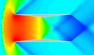
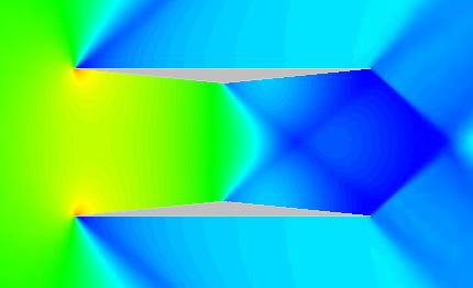
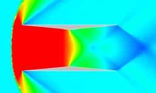
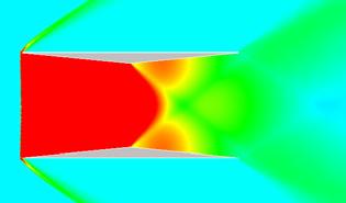

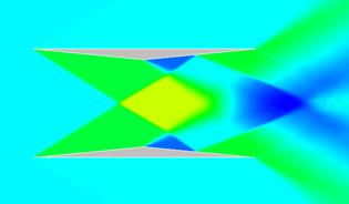

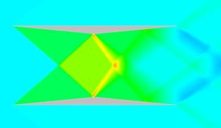
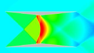
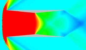
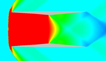

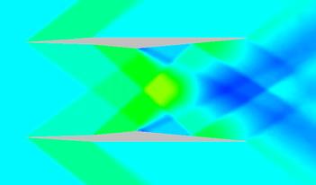
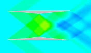
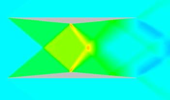
8 Kisa MATSUSHIMA UP DOWN Cd M Fig. 1. Visualization of Hysteresis Process with Cp Contour Maps. 0.1 Cd 0.0 M = A /A 1 Fig. 13. Inlet Area Control to Avoid Choking and Visualization with Cp Contour Maps. 8
9 NUMERICAL DESIGN AND ASSESSMENT OF A BIPLANE AS FUTURE SUPERSONIC TRANSPORT M Two Dimensional Model b The results confirmed the hysteresis of unstarting and starting situations. And they were found in agreement with the theory of onedimensional flow of intake diffusers. After careful analysis and consideration, by the ratio control of the inlet section areas to the throat one, hysteresis was effectively avoided as well as wave drag was significantly reduced. Finally, the ongoing study for low-boom fuselage design was introduced. We believe utilizing the above-mentioned biplane concepts will enable fuel-efficient and quiet SST to be realized. 7 Acknowledgments M M t ε C We would like to thank Professor K. Nakahashi, Professor S. Obayashi of Tohoku University and Professor A. Sasoh of Nagoya University for many valuable discussions and comments over the course of developing the present research. Three Dimensional Model Fig. 14. Concept Overview for Low-boom Fuselage [17]. analyzed. First, we revisited Busemann s biplane and confirmed the advantage of a biplane configuration in terms of wave drag reduction capability. Then, new biplane section airfoils have been designed by the inverse problem approach. The designed configuration has shown good performance. Especially when Cl>0.14, wave drag is less than that of a single flat plate airfoil. It is notable that a biplane configuration had a sufficient thickness ( t / c ), while a flat plate has no thickness. Next, the assessment of the inherent aerodynamic characteristics in a biplane was done by modern CFD. It was observed that chocking occurred over a wide range of free stream Mach numbers, from 0.5 to Moreover, simulations were run to estimate the acceleration path up to the Mach number of.6. 8 References [1] Kusunose, K. A New Concept in the Development of Boomless Supersonic Transport, Proc. First International Conference on Flow Dynamics, Sendai, Japan, November 004. [] Busemann, A. Aerodynamic lift at Supersonic Speeds, Luftfahrtforschung, Ed.1, Nr.6, Oct.3, 1935, pp [3] Liepmann, H. W. and Roshko, A., Elements of Gas Dynamics, John Wiley & Sons, Inc., New York, [4] Maruyama, D., Matsushima, K., Nakahashi, K., and Kusunose, K. Aerodynamic Design of Low Boom and Low Drag Supersonic Biplane, Proc. Second International Conference on Flow Dynamics, OS7-, November 005. [5] Yenezawa M.,Yamashita H., Goto Y., Kusunos K and Obayashi S. Wing Tip Effect of Busemann s Biplane, Proc. Second International Conference on Flow Dynamics, OS7-3, November 005. [6] Yamashita H., Yenezawa M., Goto Y., Obayashi S. and Kusunos K. CFD Analysis of Shock Wave for Busemann s Biplane, Proc. Second International Conference on Flow Dynamics, OS7-4, November 005. [7] Kusunose K., Matsushima K., Goto Y., Yamashita H., Yonezawa, Maruyama D. and Nakano T. A Fundamental Study for the Development of Boomless Supersonic Transport Aircraft, the 44th 9
10 Kisa MATSUSHIMA AIAA Aerospace Sciences Meeting and Exhibit, AIAA paper , January 006. [8] Maruyama, D., Matsushima K., Kusunose, K. and Nakahashi, K. Aerodynamic Design of Biplane Airfoils for Low Wave Drag Supersonic Flight, the 4th Applied Aerodynamics Conference, AIAA , June 006. [9] Walcher V. O. Discussion on aerodynamic drag of wings at supersonic speed using biplane concept, Luftfahrtforshung, 14, pp. 55-6, [10] Ferri A. Experiments at supersonic speed on a biplane of the Busemann type, British R.T.P Trans. No.,1407, [11] Moeckel W.E Theoretical aerodynamic coefficients of two-dimensional supersonic biplane, NACA T.N. No.1316, [1] Lighthill, M. J. A Note on Supersonic Biplane, British A.R.C. R.&M. No.00, [13] Busemann A. The relation between minimized drag and noise at supersonic speed, Proc. Conference on High-Speed Aeronautics. Poly. Inst. Brooklyn, Jan.0-, pp [14] Licher R. M. Optimum Two-dimensional Multiplanes in Supersonic Flow, Report S. M , Douglas Aircraft Co., [15] Nakahashi, K. Ito, Y., and Togashi, F Some Challenge of Realistic Flow Simulations by Unstructured Grid CFD, Int. J. Numerical Methods in Fluids, Vol. 43, pp [16] Matsushima, K. Maruyama, D., Nakano, T., and Nakahashi, K. Aerodynamic Design of Low Boom and Low Drag Supersonic Transport using Favorable Wave Interference, Proc. The 36 th JSASS Annual Meeting, April, 005, pp , 005. [17] Kusunose. K, What is the fuselage geometry of SST which generates no strong shock waves?, to be presented at the third S3T Meeting in June, 006, Aerodynamics Division of JSASS,
EXPERIMENTAL STUDY ON INTERFERENCE FLOW OF A SUPERSONIC BUSEMANN BIPLANE USING PRESSURE-SENSITIVE PAINT TECHNIQUE
 26 TH INTERNATIONAL CONGRESS OF THE AERONAUTICAL SCIENCES EXPERIMENTAL STUDY ON INTERFERENCE FLOW OF A SUPERSONIC BUSEMANN BIPLANE USING PRESSURE-SENSITIVE PAINT TECHNIQUE Hiroki Nagai*, Soshi Oyama*,
Drag Characteristics of a Low-Drag Low-Boom Supersonic Formation Flying Concept
 Drag Characteristics of a Low-Drag Low-Boom Supersonic Formation Flying Concept Yuichiro Goto, Shigeru Obayashi and Yasuaki Kohama Tohoku University, Sendai, Japan In this paper, a new concept for low-drag,
Design and Computational Studies on Plain Flaps
 Bonfring International Journal of Industrial Engineering and Management Science, Vol. 3, No. 2, June 2013 33 Design and Computational Studies on Plain Flaps M. Senthil Kumar and K. Naveen Kumar Abstract---
344 JAXA Special Publication JAXA-SP E 2. Prediction by the CFD Approach 2.1 Numerical Procedure The plane shape of the thin delta wing of the r
 5th Symposium on Integrating CFD and Experiments in Aerodynamics (Integration 2012) 343 Aerodynamic Characteristics of a Delta Wing with Arc Camber for Mars Exploration Takao Unoguchi,* 1 Shogo Aoyama,*
CFD COMPUTATION OF THE GROUND EFFECT ON AIRPLANE WITH HIGH ASPECT RATIO WING
 28 TH INTERNATIONAL CONGRESS OF THE AERONAUTICAL SCIENCES CFD COMPUTATION OF THE GROUND EFFECT ON AIRPLANE WITH HIGH ASPECT RATIO WING Sun Tae Kim*, Youngtae Kim**, Tae Kyu Reu* *Agency for Defense Development,
Numerical Investigation of Shock wave Turbulent Boundary Layer Interaction over a 2D Compression Ramp
 Advances in Aerospace Science and Applications. ISSN 2277-3223 Volume 4, Number 1 (2014), pp. 25-32 Research India Publications http://www.ripublication.com/aasa.htm Numerical Investigation of Shock wave
Analyses of Diamond - Shaped and Circular Arc Airfoils in Supersonic Wind Tunnel Airflows
 Analyses of Diamond - Shaped and Circular Arc Airfoils in Supersonic Wind Tunnel Airflows Modo U. P, Chukwuneke J. L, Omenyi Sam 1 Department of Mechanical Engineering, Nnamdi Azikiwe University, Awka,
6.1 According to Handbook of Chemistry and Physics the composition of air is
 6. Compressible flow 6.1 According to Handbook of Chemistry and Physics the composition of air is From this, compute the gas constant R for air. 6. The figure shows a, Pitot-static tube used for velocity
High Speed Aerodynamics. Copyright 2009 Narayanan Komerath
 Welcome to High Speed Aerodynamics 1 Lift, drag and pitching moment? Linearized Potential Flow Transformations Compressible Boundary Layer WHAT IS HIGH SPEED AERODYNAMICS? Airfoil section? Thin airfoil
Steady waves in compressible flow
 Chapter Steady waves in compressible flow. Oblique shock waves Figure. shows an oblique shock wave produced when a supersonic flow is deflected by an angle. Figure.: Flow geometry near a plane oblique
Given the water behaves as shown above, which direction will the cylinder rotate?
 water stream fixed but free to rotate Given the water behaves as shown above, which direction will the cylinder rotate? ) Clockwise 2) Counter-clockwise 3) Not enough information F y U 0 U F x V=0 V=0
Brenda M. Kulfan, John E. Bussoletti, and Craig L. Hilmes Boeing Commercial Airplane Group, Seattle, Washington, 98124
 AIAA--2007-0684 Pressures and Drag Characteristics of Bodies of Revolution at Near Sonic Speeds Including the Effects of Viscosity and Wind Tunnel Walls Brenda M. Kulfan, John E. Bussoletti, and Craig
An Investigation of the Attainable Efficiency of Flight at Mach One or Just Beyond
 An Investigation of the Attainable Efficiency of Flight at Mach One or Just Beyond Antony Jameson Department of Aeronautics and Astronautics AIAA Aerospace Sciences Meeting, Reno, NV AIAA Paper 2007-0037
NUMERICAL OPTIMIZATION OF THE SHAPE OF A HOLLOW PROJECTILE
 NUMERICAL OPTIMIZATION OF THE SHAPE OF A HOLLOW PROJECTILE Wessam Mahfouz Elnaggar, Zhihua Chen and Hui Zhang Key Laboratory of Transient Physics, Nanjing University of Science and Technology, Nanjing,
ADVERSE REYNOLDS NUMBER EFFECT ON MAXIMUM LIFT OF TWO DIMENSIONAL AIRFOILS
 ICAS 2 CONGRESS ADVERSE REYNOLDS NUMBER EFFECT ON MAXIMUM LIFT OF TWO DIMENSIONAL AIRFOILS Kenji YOSHIDA, Masayoshi NOGUCHI Advanced Technology Aircraft Project Center NATIONAL AEROSPACE LABORATORY 6-
The Study on Re Effect Correction for Laminar Wing with High Lift
 The Study on Re Effect Correction for Laminar Wing with High Lift Jieke Yao, Wenliang Feng, Lingying Lv and Bin Chen Chengdu Aircraft Industrial (group) CO.LTD, 692, Chengdu, China Abstract. In the past
Drag Computation (1)
") Drag Computation (1) Why drag so concerned Its effects on aircraft performances On the Concorde, one count drag increase ( C D =.0001) requires two passengers, out of the 90 ~ 100 passenger capacity, be
Drag Computation (1) Why drag so concerned Its effects on aircraft performances On the Concorde, one count drag increase ( C D =.0001) requires two passengers, out of the 90 ~ 100 passenger capacity, be
AIRFRAME NOISE MODELING APPROPRIATE FOR MULTIDISCIPLINARY DESIGN AND OPTIMIZATION
 AIRFRAME NOISE MODELING APPROPRIATE FOR MULTIDISCIPLINARY DESIGN AND OPTIMIZATION AIAA-2004-0689 Serhat Hosder, Joseph A. Schetz, Bernard Grossman and William H. Mason Virginia Tech Work sponsored by NASA
Configuration Aerodynamics
 Configuration Aerodynamics William H. Mason Virginia Tech Blacksburg, VA The front cover of the brochure describing the French Exhibit at the Montreal Expo, 1967. January 2018 W.H. Mason CONTENTS i CONTENTS
CFD Analysis of Micro-Ramps for Hypersonic Flows Mogrekar Ashish 1, a, Sivakumar, R. 2, b
 Applied Mechanics and Materials Submitted: 2014-04-25 ISSN: 1662-7482, Vols. 592-594, pp 1962-1966 Revised: 2014-05-07 doi:10.4028/www.scientific.net/amm.592-594.1962 Accepted: 2014-05-16 2014 Trans Tech
Compressible Potential Flow: The Full Potential Equation. Copyright 2009 Narayanan Komerath
 Compressible Potential Flow: The Full Potential Equation 1 Introduction Recall that for incompressible flow conditions, velocity is not large enough to cause density changes, so density is known. Thus
I. Introduction. external compression. supersonic flow. II. Design Criteria
 Design Optimization of High Speed Inlets Doyle D Knight Dept of Mechanical and Aerospace Engineering Rutgers - The State University of New Jersey New Brunswick, NJ 08903 knight@soemailrutgersedu I Introduction
Module3: Waves in Supersonic Flow Lecture14: Waves in Supersonic Flow (Contd.)
") 1 Module3: Waves in Supersonic Flow Lecture14: Waves in Supersonic Flow (Contd.) Mach Reflection: The appearance of subsonic regions in the flow complicates the problem. The complications are also encountered
1 Module3: Waves in Supersonic Flow Lecture14: Waves in Supersonic Flow (Contd.) Mach Reflection: The appearance of subsonic regions in the flow complicates the problem. The complications are also encountered
An Investigation of the Attainable Efficiency of Flight at Mach One or Just Beyond
 45 th Aerospace Sciences Meeting and Exhibit, January 8 11, 2007, Reno, Nevada An Investigation of the Attainable Efficiency of Flight at Mach One or Just Beyond Antony Jameson Department of Aeronautics
Aerodynamic Investigation of a 2D Wing and Flows in Ground Effect
 26 2 2009 3 CHINESE JOURNAL OF COMPUTATIONAL PHYSICS Vol. 26,No. 2 Mar., 2009 Article ID : 10012246 X(2009) 0220231210 Aerodynamic Investigation of a 2D Wing and Flows in Ground Effect YANG Wei, YANG Zhigang
MULTIGRID CALCULATIONS FOB. CASCADES. Antony Jameson and Feng Liu Princeton University, Princeton, NJ 08544
 MULTIGRID CALCULATIONS FOB. CASCADES Antony Jameson and Feng Liu Princeton University, Princeton, NJ 0544 1. Introduction Development of numerical methods for internal flows such as the flow in gas turbines
Challenges and Complexity of Aerodynamic Wing Design
 Chapter 1 Challenges and Complexity of Aerodynamic Wing Design Kasidit Leoviriyakit and Antony Jameson Department of Aeronautics and Astronautics Stanford University, Stanford CA kasidit@stanford.edu and
SENSITIVITY ANALYSIS OF THE FACTORS AFFECTING FORCE GENERATION BY WING FLAPPING MOTION
 Proceedings of the ASME 2013 International Mechanical Engineering Congress and Exposition IMECE2013 November 15-21, 2013, San Diego, California, USA IMECE2013-65472 SENSITIVITY ANALYSIS OF THE FACTORS
A Novel Airfoil Circulation Augment Flow Control Method Using Co-Flow Jet
 AIAA Paper 2004-2208, 2004 A Novel Airfoil Circulation Augment Flow Control Method Using Co-Flow Jet Ge-Cheng Zha and Craig D. Paxton Dept. of Mechanical & Aerospace Engineering University of Miami Coral
Chapter 5 Wing design - selection of wing parameters 2 Lecture 20 Topics
 Chapter 5 Wing design - selection of wing parameters Lecture 0 Topics 5..4 Effects of geometric parameters, Reynolds number and roughness on aerodynamic characteristics of airfoils 5..5 Choice of airfoil
CHAPTER 3 ANALYSIS OF NACA 4 SERIES AIRFOILS
 54 CHAPTER 3 ANALYSIS OF NACA 4 SERIES AIRFOILS The baseline characteristics and analysis of NACA 4 series airfoils are presented in this chapter in detail. The correlations for coefficient of lift and
OpenFOAM Simulations for MAV Applications
 16 th Annual CFD Symposium 11th-12th August 2014, Bangalore 1 OpenFOAM Simulations for MAV Applications Syed Zahid*, A. Rajesh, M.B. Subrahmanya, B.N. Rajani *Student, Dept. of Mech. Engg, SDM, Dharwad,
COMPUTATIONAL SIMULATION OF THE FLOW PAST AN AIRFOIL FOR AN UNMANNED AERIAL VEHICLE
 COMPUTATIONAL SIMULATION OF THE FLOW PAST AN AIRFOIL FOR AN UNMANNED AERIAL VEHICLE L. Velázquez-Araque 1 and J. Nožička 2 1 Division of Thermal fluids, Department of Mechanical Engineering, National University
Simulation of Aeroelastic System with Aerodynamic Nonlinearity
 Simulation of Aeroelastic System with Aerodynamic Nonlinearity Muhamad Khairil Hafizi Mohd Zorkipli School of Aerospace Engineering, Universiti Sains Malaysia, Penang, MALAYSIA Norizham Abdul Razak School
COMPUTATIONAL METHOD
 Multi Objective Design Optimization of Rocket Engine Turbopump Turbine Naoki Tani, Akira Oyama and Nobuhiro Yamanishi tani.naoki@jaxa.jp Japan Aerospace Exploration Agency JAXA is now planning to develop
Numerical Investigation of Wind Tunnel Wall Effects on a Supersonic Finned Missile
 16 th International Conference on AEROSPACE SCIENCES & AVIATION TECHNOLOGY, ASAT - 16 May 26-28, 2015, E-Mail: asat@mtc.edu.eg Military Technical College, Kobry Elkobbah, Cairo, Egypt Tel : +(202) 24025292
AOE 3114 Compressible Aerodynamics
 AOE 114 Compressible Aerodynamics Primary Learning Objectives The student will be able to: 1. Identify common situations in which compressibility becomes important in internal and external aerodynamics
WALL ROUGHNESS EFFECTS ON SHOCK BOUNDARY LAYER INTERACTION FLOWS
 ISSN (Online) : 2319-8753 ISSN (Print) : 2347-6710 International Journal of Innovative Research in Science, Engineering and Technology An ISO 3297: 2007 Certified Organization, Volume 2, Special Issue
A COUPLED-ADJOINT METHOD FOR HIGH-FIDELITY AERO-STRUCTURAL OPTIMIZATION
 A COUPLED-ADJOINT METHOD FOR HIGH-FIDELITY AERO-STRUCTURAL OPTIMIZATION Joaquim Rafael Rost Ávila Martins Department of Aeronautics and Astronautics Stanford University Ph.D. Oral Examination, Stanford
ACTIVE SEPARATION CONTROL ON A SLATLESS 2D HIGH-LIFT WING SECTION
 26th INTERNATIONAL CONGRESS OF THE AERONAUTICAL SCIENCES ACTIVE SEPARATION CONTROL ON A SLATLESS 2D HIGH-LIFT WING SECTION F. Haucke, I. Peltzer, W. Nitsche Chair for Aerodynamics Department of Aeronautics
Continuity Equation for Compressible Flow
 Continuity Equation for Compressible Flow Velocity potential irrotational steady compressible Momentum (Euler) Equation for Compressible Flow Euler's equation isentropic velocity potential equation for
A Numerical Study of Circulation Control on a Flapless UAV
 Ninth International Conference on Computational Fluid Dynamics (ICCFD9), Istanbul, Turkey, July 11-15, 2016 ICCFD9-xxxx A Numerical Study of Circulation Control on a Flapless UAV Huaixun Ren 1, Weimin
Far Field Noise Minimization Using an Adjoint Approach
 Far Field Noise Minimization Using an Adjoint Approach Markus P. Rumpfkeil and David W. Zingg University of Toronto Institute for Aerospace Studies 4925 Dufferin Street, Toronto, Ontario, M3H 5T6, Canada
The Computations of Jet Interaction on a Generic Supersonic Missile
 The Computations of Jet Interaction on a Generic Supersonic Missile *Jinbum Huh 1) and Seungsoo Lee 2) 1), 2) Department of Aerospace Engineering, Inha Univ., Incheon, Korea 2) slee@inha.ac.kr ABSTRACT
AERODYNAMIC CHARACTERIZATION OF A CANARD GUIDED ARTILLERY PROJECTILE
 45th AIAA Aerospace Sciences Meeting and Exhibit 8-11 January 27, Reno, Nevada AIAA 27-672 AERODYNAMIC CHARACTERIZATION OF A CANARD GUIDED ARTILLERY PROJECTILE Wei-Jen Su 1, Curtis Wilson 2, Tony Farina
Thin airfoil theory. Chapter Compressible potential flow The full potential equation
 hapter 4 Thin airfoil theory 4. ompressible potential flow 4.. The full potential equation In compressible flow, both the lift and drag of a thin airfoil can be determined to a reasonable level of accuracy
RECENT near-sonic and low-sonic boom transport aircraft
 JOURNAL OF AIRCRAFT Vol. 44, No. 6, November December 2007 Aerodynamic Characteristics of Bodies of Revolution at Near-Sonic Speeds Brenda M. Kulfan, John E. Bussoletti, and Craig L. Hilmes The Boeing
ADVANCES in NATURAL and APPLIED SCIENCES
 ADVANCES in NATURAL and APPLIED SCIENCES ISSN: 1995-0772 Published BY AENSI Publication EISSN: 1998-1090 http://www.aensiweb.com/anas 2016 Special 10(6): pages 79-88 Open Access Journal Effect of Variable
AEROSPACE ENGINEERING DEPARTMENT. Second Year - Second Term ( ) Fluid Mechanics & Gas Dynamics
 Fluid Mechanics & Gas Dynamics") AEROSPACE ENGINEERING DEPARTMENT Second Year - Second Term (2008-2009) Fluid Mechanics & Gas Dynamics Similitude,Dimensional Analysis &Modeling (1) [7.2R*] Some common variables in fluid mechanics include:
AEROSPACE ENGINEERING DEPARTMENT Second Year - Second Term (2008-2009) Fluid Mechanics & Gas Dynamics Similitude,Dimensional Analysis &Modeling (1) [7.2R*] Some common variables in fluid mechanics include:
Given a stream function for a cylinder in a uniform flow with circulation: a) Sketch the flow pattern in terms of streamlines.
 Sketch the flow pattern in terms of streamlines.") Question Given a stream function for a cylinder in a uniform flow with circulation: R Γ r ψ = U r sinθ + ln r π R a) Sketch the flow pattern in terms of streamlines. b) Derive an expression for the angular
Question Given a stream function for a cylinder in a uniform flow with circulation: R Γ r ψ = U r sinθ + ln r π R a) Sketch the flow pattern in terms of streamlines. b) Derive an expression for the angular
Mechanics of Flight. Warren F. Phillips. John Wiley & Sons, Inc. Professor Mechanical and Aerospace Engineering Utah State University WILEY
 Mechanics of Flight Warren F. Phillips Professor Mechanical and Aerospace Engineering Utah State University WILEY John Wiley & Sons, Inc. CONTENTS Preface Acknowledgments xi xiii 1. Overview of Aerodynamics
Drag (2) Induced Drag Friction Drag Form Drag Wave Drag
 Induced Drag Friction Drag Form Drag Wave Drag") Drag () Induced Drag Friction Drag Form Drag Wave Drag Outline Nomenclature and Concepts Farfield Drag Analysis Induced Drag Multiple Lifting Surfaces Zero Lift Drag :Friction and Form Drag Supersonic
Drag () Induced Drag Friction Drag Form Drag Wave Drag Outline Nomenclature and Concepts Farfield Drag Analysis Induced Drag Multiple Lifting Surfaces Zero Lift Drag :Friction and Form Drag Supersonic
Nonlinear Aeroelastic Analysis of a Wing with Control Surface Freeplay
 Copyright c 7 ICCES ICCES, vol., no.3, pp.75-8, 7 Nonlinear Aeroelastic Analysis of a with Control Surface Freeplay K.S. Kim 1,J.H.Yoo,J.S.Bae 3 and I. Lee 1 Summary In this paper, nonlinear aeroelastic
APPLICATION OF SPACE-TIME MAPPING ANALYSIS METHOD TO UNSTEADY NONLINEAR GUST-AIRFOIL INTERACTION PROBLEM
 AIAA 2003-3693 APPLICATION OF SPACE-TIME MAPPING ANALYSIS METHOD TO UNSTEADY NONLINEAR GUST-AIRFOIL INTERACTION PROBLEM Vladimir V. Golubev* and Axel Rohde Embry-Riddle Aeronautical University Daytona
FUNDAMENTALS OF AERODYNAMICS
 *A \ FUNDAMENTALS OF AERODYNAMICS Second Edition John D. Anderson, Jr. Professor of Aerospace Engineering University of Maryland H ' McGraw-Hill, Inc. New York St. Louis San Francisco Auckland Bogota Caracas
COMPLETE CONFIGURATION AERO-STRUCTURAL OPTIMIZATION USING A COUPLED SENSITIVITY ANALYSIS METHOD
 COMPLETE CONFIGURATION AERO-STRUCTURAL OPTIMIZATION USING A COUPLED SENSITIVITY ANALYSIS METHOD Joaquim R. R. A. Martins Juan J. Alonso James J. Reuther Department of Aeronautics and Astronautics Stanford
Effect of Camber on Badminton Shuttlecock
 Proceedings Effect of Camber on Badminton Shuttlecock Yasufumi Konishi 1, *, Yusuke Matsushima 2, Takashi Misaka 1, Hiroyuki Okuizumi 1, Kensuke Tanaka 2 and Shigeru Obayashi 1 1 Institute of Fluid Science,
Paul Garabedian s Contributions to Transonic Airfoil and Wing Design
 Paul Garabedian s Contributions to Transonic Airfoil and Wing Design Antony Jameson October 13, 010 Abstract This note on Paul Garabedian s work on transonic airfoil and wing design is written from the
Stability Characteristics of Supersonic Natural Laminar Flow Wing Design Concept
 50th AIAA Aerospace Sciences Meeting including the New Horizons Forum and Aerospace Exposition 09-12 January 2012, Nashville, Tennessee AIAA 2012-0021 Stability Characteristics of Supersonic Natural Laminar
Transonic Flutter Prediction of Supersonic Jet Trainer with Various External Store Configurations
 Transonic Flutter Prediction of Supersonic Jet Trainer with Various External Store Configurations In Lee * Korea Advanced Institute of Science and Technology, Daejeon, 305-701, Korea Hyuk-Jun Kwon Agency
AERO-STRUCTURAL WING DESIGN OPTIMIZATION USING HIGH-FIDELITY SENSITIVITY ANALYSIS
 AERO-STRUCTURAL WING DESIGN OPTIMIZATION USING HIGH-FIDELITY SENSITIVITY ANALYSIS Joaquim R. R. A. Martins and Juan J. Alonso Department of Aeronautics and Astronautics Stanford University, Stanford, CA
Experimental Evaluation of Aerodynamics Characteristics of a Baseline Airfoil
 Research Paper American Journal of Engineering Research (AJER) e-issn: 2320-0847 p-issn : 2320-0936 Volume-4, Issue-1, pp-91-96 www.ajer.org Open Access Experimental Evaluation of Aerodynamics Characteristics
Propulsion Systems and Aerodynamics MODULE CODE LEVEL 6 CREDITS 20 Engineering and Mathematics Industrial Collaborative Engineering
 TITLE Propulsion Systems and Aerodynamics MODULE CODE 55-6894 LEVEL 6 CREDITS 20 DEPARTMENT Engineering and Mathematics SUBJECT GROUP Industrial Collaborative Engineering MODULE LEADER Dr. Xinjun Cui DATE
Development of Multi-Disciplinary Simulation Codes and their Application for the Study of Future Space Transport Systems
 24 TH INTERNATIONAL CONGRESS OF THE AERONAUTICAL SCIENCES Development of Multi-Disciplinary Simulation Codes and their Application for the Study of Future Space Transport Systems Yukimitsu. Yamamoto JAPAN
Computational Fluid Dynamics Study Of Fluid Flow And Aerodynamic Forces On An Airfoil S.Kandwal 1, Dr. S. Singh 2
 Computational Fluid Dynamics Study Of Fluid Flow And Aerodynamic Forces On An Airfoil S.Kandwal 1, Dr. S. Singh 2 1 M. Tech Scholar, 2 Associate Professor Department of Mechanical Engineering, Bipin Tripathi
Performance Investigation of High Pressure Ratio Centrifugal Compressor using CFD
 International Journal of Ignited Minds (IJIMIINDS) Performance Investigation of High Pressure Ratio Centrifugal Compressor using CFD Manjunath DC a, Rajesh b, Dr.V.M.Kulkarni c a PG student, Department
Further Studies of Airfoils Supporting Non-unique Solutions in Transonic Flow
 29th AIAA Applied Aerodynamics Conference 27-30 June 2011, Honolulu, Hawaii AIAA 2011-3509 Further Studies of Airfoils Supporting Non-unique Solutions in Transonic Flow Antony Jameson, John C. Vassberg,
CALCULATION OF PRESSURE FIELD IN THE PROBLEM OF SONIC BOOM FROM VARIOUS THIN AXISYMMETRIC BODIES
 CALCULATION OF PRESSURE FIELD IN THE PROBLEM OF SONIC BOOM FROM VARIOUS THIN AXISYMMETRIC BODIES А.V. Potapkin, D.Yu. Moskvichev Khristianovich Institute of Theoretical and Applied Mechanics SB RAS 630090,
Feedback Control of Aerodynamic Flows
 44th AIAA Aerospace Sciences Meeting and Exhibit 9-12 January 26, Reno, Nevada AIAA 26-843 44th AIAA Aerospace Sciences Meeting and Exhibit, Reno, Nevada, 9 12 Jan, 26. Feedback Control of Aerodynamic
Introduction to Aeronautics
 Introduction to Aeronautics ARO 101 Sections 03 & 04 Sep 30, 2015 thru Dec 9, 2015 Instructor: Raymond A. Hudson Week #8 Lecture Material 1 Topics For Week #8 Airfoil Geometry & Nomenclature Identify the
Limit Cycle Oscillations of a Typical Airfoil in Transonic Flow
 Limit Cycle Oscillations of a Typical Airfoil in Transonic Flow Denis B. Kholodar, United States Air Force Academy, Colorado Springs, CO 88 Earl H. Dowell, Jeffrey P. Thomas, and Kenneth C. Hall Duke University,
Lecture-4. Flow Past Immersed Bodies
 Lecture-4 Flow Past Immersed Bodies Learning objectives After completing this lecture, you should be able to: Identify and discuss the features of external flow Explain the fundamental characteristics
1. (20 pts total 2pts each) - Circle the most correct answer for the following questions.
 - Circle the most correct answer for the following questions.") ME 50 Gas Dynamics Spring 009 Final Exam NME:. (0 pts total pts each) - Circle the most correct answer for the following questions. i. normal shock propagated into still air travels with a speed (a) equal
ME 50 Gas Dynamics Spring 009 Final Exam NME:. (0 pts total pts each) - Circle the most correct answer for the following questions. i. normal shock propagated into still air travels with a speed (a) equal
Investigation potential flow about swept back wing using panel method
 INTERNATIONAL JOURNAL OF ENERGY AND ENVIRONMENT Volume 7, Issue 4, 2016 pp.317-326 Journal homepage: www.ijee.ieefoundation.org Investigation potential flow about swept back wing using panel method Wakkas
Is My CFD Mesh Adequate? A Quantitative Answer
 Is My CFD Mesh Adequate? A Quantitative Answer Krzysztof J. Fidkowski Gas Dynamics Research Colloqium Aerospace Engineering Department University of Michigan January 26, 2011 K.J. Fidkowski (UM) GDRC 2011
Adjustment of k ω SST turbulence model for an improved prediction of stalls on wind turbine blades
 Adjustment of k ω SST turbulence model for an improved prediction of stalls on wind turbine blades Tawit Chitsomboon *, Chalothorn Thamthae School of Mechanical Engineering, Institute of Engineering, Suranaree
Royal Aeronautical Society 2016 Applied Aerodynamics Conference Tuesday 19 th Thursday 21 st July Science Centre, Bristol, UK
 Assessment and validation of aerodynamic performance results for a Natural Laminar Flow transonic wing tested in cryogenic conditions via simulation of turbulent wedges in CFD. Royal Aeronautical Society
Transonic Aerodynamics Wind Tunnel Testing Considerations. W.H. Mason Configuration Aerodynamics Class
 Transonic Aerodynamics Wind Tunnel Testing Considerations W.H. Mason Configuration Aerodynamics Class Transonic Aerodynamics History Pre WWII propeller tip speeds limited airplane speed Props did encounter
NUMERICAL INVESTIGATION OF VERTICAL AXIS WIND TURBINE WITH TWIST ANGLE IN BLADES
 Eleventh International Conference on CFD in the Minerals and Process Industries CSIRO, Melbourne, Australia 7-9 December 05 NUMERICAL INVESTIGATION OF VERTICAL AXIS WIND TURBINE WITH TWIST ANGLE IN BLADES
International Journal of Modern Trends in Engineering and Research e-issn No.: , Date: 2-4 July, 2015
 International Journal of Modern Trends in Engineering and Research www.ijmter.com e-issn No.:2349-9745, Date: 2-4 July, 2015 CFD Analysis of Airfoil NACA0012 Pritesh S. Gugliya 1, Yogesh R. Jaiswal 2,
Design of a Droopnose Configuration for a Coanda Active Flap Application. Marco Burnazzi and Rolf Radespiel
 Design of a Droopnose Configuration for a Coanda Active Flap Application Marco Burnazzi and Rolf Radespiel Institute of Fluid Mechanics, Technische Universität Braunschweig, 38108 Braunschweig, Germany
CHAPTER 4 OPTIMIZATION OF COEFFICIENT OF LIFT, DRAG AND POWER - AN ITERATIVE APPROACH
 82 CHAPTER 4 OPTIMIZATION OF COEFFICIENT OF LIFT, DRAG AND POWER - AN ITERATIVE APPROACH The coefficient of lift, drag and power for wind turbine rotor is optimized using an iterative approach. The coefficient
EVALUATION OF EFFECT OF SHAPE AND LENGTH OF SPIKE ON AERODYNAMICS PERFORMANCE OF SUPERSONIC AXI-SYMMETRIC BODIES
 International Journal of Mechanical and Production Engineering Research and Development (IJMPERD) ISSN (P): 2249-6890; ISSN (E): 2249-8001 Vol. 8, Issue 1, Feb 2018, 133-144 TJPRC Pvt. Ltd. EVALUATION
Studies on the Transition of the Flow Oscillations over an Axisymmetric Open Cavity Model
 Advances in Aerospace Science and Applications. ISSN 2277-3223 Volume 3, Number 2 (2013), pp. 83-90 Research India Publications http://www.ripublication.com/aasa.htm Studies on the Transition of the Flow
Numerical Analysis of Active Cascade Flutter Control with Smart Structure
 Proceedings of the International Gas Turbine Congress Tokyo November -7, IGTCTokyo TS-55 Numerical Analysis of Active Cascade Flutter Control with Smart Structure Junichi Kazawa and Toshinori Watanabe
Design and Optimization of De Lavel Nozzle to Prevent Shock Induced Flow Separation
 Advances in Aerospace Science and Applications. ISSN 2277-3223 Volume 3, Number 2 (2013), pp. 119-124 Research India Publications http://www.ripublication.com/aasa.htm Design and Optimization of De Lavel
COMPUTATIONAL STUDY OF SEPARATION CONTROL MECHANISM WITH THE IMAGINARY BODY FORCE ADDED TO THE FLOWS OVER AN AIRFOIL
 COMPUTATIONAL STUDY OF SEPARATION CONTROL MECHANISM WITH THE IMAGINARY BODY FORCE ADDED TO THE FLOWS OVER AN AIRFOIL Kengo Asada 1 and Kozo Fujii 2 ABSTRACT The effects of body force distribution on the
Computational Analysis of Scramjet Inlet
 ISSN (Online) : 2319-8753 ISSN (Print) : 2347-6710 International Journal of Innovative Research in Science, Engineering and Technology Volume 3, Special Issue 3, March 2014 2014 IEEE International Conference
Design and simulation of Open Circuit Blowdown type Wind Tunnel
 Design and simulation of Open Circuit Blowdown type Wind Tunnel Sanjeev Kumar Gupta a, V.K.Dwivedi b, Jitendra Kumar Chauhan c, and Rahul Goswami c a Assistant Professor, Department of Mechanical Engineering,
Computational Investigations of High-Speed Dual-Stream Jets
 9th AIAA/CEAS Aeroacoustics Conference and Exhibit -4 May 3, Hilton Head, South Carolina AIAA 3-33 Computational Investigations of High-Speed Dual-Stream Jets Nicholas J. Georgiadis * National Aeronautics
LONGITUDINAL STABILITY AND TRIM OF AN ARIANE 5 FLY-BACK BOOSTER
 12th AIAA International Space Planes and Hypersonic Systems and Technologies 1-19 December 23, Norfolk, Virginia AIAA 23-7 LONGITUDINAL STABILITY AND TRIM OF AN ARIANE FLY-BACK BOOSTER Th. Eggers DLR,
Flight Vehicle Terminology
 Flight Vehicle Terminology 1.0 Axes Systems There are 3 axes systems which can be used in Aeronautics, Aerodynamics & Flight Mechanics: Ground Axes G(x 0, y 0, z 0 ) Body Axes G(x, y, z) Aerodynamic Axes
Optimization of Divergent Angle of a Rocket Engine Nozzle Using Computational Fluid Dynamics
 The International Journal Of Engineering And Science (Ijes) Volume 2 Issue 2 Pages 196-207 2013 Issn: 2319 1813 Isbn: 2319 1805 Optimization of Divergent Angle of a Rocket Engine Nozzle Using Computational
Attached and Detached Eddy Simulation
 Attached and Detached Eddy Simulation Philippe R. Spalart Boeing Commercial Airplanes, Seattle, USA Mikhail K. Strelets Saint-Petersburg Polytechnic University and New Technologies and Services (NTS),
Aerothermodynamics of High Speed Flows
 Aerothermodynamics of High Speed Flows Lecture 5: Nozzle design G. Dimitriadis 1 Introduction Before talking about nozzle design we need to address a very important issue: Shock reflection We have already
AEROSPACE ENGINEERING
 AEROSPACE ENGINEERING Subject Code: AE Course Structure Sections/Units Topics Section A Engineering Mathematics Topics (Core) 1 Linear Algebra 2 Calculus 3 Differential Equations 1 Fourier Series Topics
Introduction to Aerospace Engineering
 4. Basic Fluid (Aero) Dynamics Introduction to Aerospace Engineering Here, we will try and look at a few basic ideas from the complicated field of fluid dynamics. The general area includes studies of incompressible,
FREQUENCY DOMAIN FLUTTER ANALYSIS OF AIRCRAFT WING IN SUBSONIC FLOW
 FREQUENCY DOMAIN FLUTTER ANALYSIS OF AIRCRAFT WING IN SUBSONIC FLOW Ms.K.Niranjana 1, Mr.A.Daniel Antony 2 1 UG Student, Department of Aerospace Engineering, Karunya University, (India) 2 Assistant professor,
Investigation on Boundary Layer Ingestion Propulsion for UAVs
 International Micro Air Vehicle Conference and Flight Competition (IMAV) 2017 293 Investigation on Boundary Layer Ingestion Propulsion for UAVs L. Teperin, M. El-Salamony, A. Moharam, and M. Shehata, Central
IX. COMPRESSIBLE FLOW. ρ = P
 IX. COMPRESSIBLE FLOW Compressible flow is the study of fluids flowing at speeds comparable to the local speed of sound. This occurs when fluid speeds are about 30% or more of the local acoustic velocity.