CRACK BIFURCATION AS A RETARDATION MECHANISM
|
|
|
- Moses Webster
- 5 years ago
- Views:
Transcription
1 ORAL/POSTER REFERENCE: FT288 CRACK BIFURCATION AS A RETARDATION MECHANISM A.C.O. Miranda 1, M.A. Meggiolaro 2, J.T.P. Castro 2, L.F. Martha 3 1 Tecgraf - Computer Graphics Technology Group, 2 Department of Mechanical Engineering, 3 Department of Civil Engineering, Pontifical Catholic University of Rio de Janeiro, Rio de Janeiro, RJ, , Brazil ABSTRACT In this work, a FE program is developed to calculate the path and associated SIF of branched cracks, validated through experiments on 4340 steel ESE(T) specimens. It is shown that very small differences between the lengths of the bifurcated branches are sufficient to cause the shorter one to eventually arrest as the longer branch returns to the pre-overload conditions. Crack retardation equations are proposed to predict the propagation behavior of branched cracks in an arbitrary structure, considering the possible interaction with other retardation mechanisms. These equations are fitted from a total of 6,250 FE calculations to the process zone size and crack retardation factor along the curved crack branches. From these quantitative results, it is shown that crack bifurcation may provide a sound alternative mechanistic explanation for overload-induced fatigue crack retardation on structural components when Elberian arguments cannot be used, in special for load interaction effects under closure-free conditions at high R-ratios, or when the closure load decreases after the overloads, as observed at low R-ratios under plane strain conditions. KEYWORDS Crack retardation model, Bifurcated cracks, Finite elements, Life prediction INTRODUCTION Fatigue cracks can significantly deviate from their Mode I growth direction due to the influence of overloads, multi-axial stresses, micro structural inhomogeneities (such as inclusions, grain boundaries and interfaces), or environmental effects, generating crack kinking or branching [1]. A fatigue crack deviated from its nominal Mode I plane induces mixed-mode near-tip conditions even if the far-field stress is pure traction. For instance, a pure Mode I stress intensity factor (SIF) K I locally induces Modes I and II SIF k 1 and k 2 near the longer branch b of a bifurcated crack and k 1 and k 2 near the shorter c one. The equivalent SIF K b and K c of the longer and shorter branches, calculated respectively from (k 1, k 2 ) and (k 1, k 2 ) using e.g. the σ θmax criterion [2], can be considerably smaller than that of a straight crack with the same projected (on the original crack plane) length. Therefore, such branching can retard or even arrest subsequent crack growth [3]. Some analytical solutions have been obtained for the SIF of kinked and branched cracks, but it is generally recognized that it is very difficult to develop accurate analytical solutions to (for?) their complex propagation behavior [4-8]. Therefore, numerical methods such as Finite Elements (FE) and Boundary Elements (BE) are the only practical means to predict the propagation behavior of branched cracks [9]. To accomplish that, a specially developed interactive FE program named Quebra (meaning fracture in Portuguese) is used [10].
2 PROPAGATION OF BRANCHED CRACKS The growth of branched cracks is studied using the Quebra program to model a C(T) specimen with width w = 32.0mm, crack length a = 14.9mm, and a very small bifurcation with angle 2θ ranging from 40 o to 168 o, initial longer branch length b 0 = 10µm and initial shorter branch lengths ranging from c 0 = 5µm to 10µm. A fixed crack growth step of b = 3µm (or 1µm during the first propagation steps) is considered for the propagation of the longer branch b. This growth step is calculated in the direction defined by the σ θmax criterion [2]. Due to the differences in the SIF and crack growth rate, a growth step c smaller than b is expected for the shorter branch. This smaller step is obtained assuming a crack propagation law that models the first two growth phases, da = A [ K K m th ( R )] dn (1) where A and m are material constants and K th (R) is the fatigue crack propagation threshold at the R = K min /K max ratio of the test. If K b and K c are respectively the stress intensity ranges of the longer and shorter branches, then the growth step c of the shorter branch c should be Kc Kth( R) ( ( R) ) m c = b (2) Kb Kth Interestingly, the ratio between the propagation rates of the two branches is independent of the material constant A. In this analysis, the exponent m is assumed to be 2.0, 3.0, and 4.0, which are representative for the range of the measured exponents for structural alloys. A similar expression can be obtained if other crack retardation mechanisms are considered, through Lang and Marci s propagation threshold K PR [11] with A and m parameters fitted for each considered load ratio R: Kmax, c K PR c = b ( ) m (3) K K max, b where K max,b and K max,c are the maximum SIF of the longer and shorter branches respectively. Or else this threshold K PR can be replaced by a limiting value PR * max K, the threshold of the maximum of Sadananda and Vasudevan s Unified Approach [12, 13], which assumes that a crack can propagate only when and K max * max * th > K, where K = K ( R 1). th * K > K th Both the crack path and the associated SIF along each branch are obtained using the Quebra program. Several calculations were performed for different values of the exponent m, bifurcation angle 2θ, relation c 0 /b 0, and SIF, considering or not the effect of K PR, as described next. Branched crack propagation with K PR = 0 In this section, the propagation behavior of branched cracks is studied using FE but neglecting any retardation mechanism other than the bifurcation itself (i.e. assuming K PR = 0). Figure 3 shows the crack paths obtained from the FE analyses of bifurcated cracks with 2θ = 130 o and c 0 /b 0 = {0.5, 0.8, 0.95, 1}, considering m = 2 and K PR = 0. The dashed lines show the theoretical propagation behavior of a perfectly symmetric bifurcation (c 0 /b 0 = 1). In this case, the retardation effect would never end because both branches would propagate symmetrically without arresting. Clearly, such behavior is not observed in practice, since the slightest difference between b 0 and c 0 would be sufficient to induce an asymmetrical behavior. Figure 1 also shows that lower c 0 /b 0 ratios result in premature arrest of the shorter crack branch, leading to smaller retardation zones. Also, the propagation path of the longer branch is usually restrained to the region within the dashed lines, while the shorter one is pushed outside that envelope due to shielding effects.
3 Figure 1: Bifurcated crack paths for several c 0 /b 0 ratios (K PR = 0). The size of the retardation zone can be estimated from the ratio b f /b 0, where b f is the value of the length parameter b of the longer branch (measured along the crack path) beyond which the retardation effect ends. The ratio b f /b 0 is then calculated through FE propagation simulations for all combinations of c 0 /b 0 = {0.5, 0.8, 0.9, 0.95}, 2θ = {40 o, 80 o, 130 o, 168 o } and m = {2, 3, 4}, and fitted by the proposed empirical function: b b f o exp 2 θ 30o = (1 / ) ( 2) 2 / 3 c + m (12 )/20 0 b m 0 (4) The FE-calculated equivalent SIF K b and K c of the longer and shorter branches are now evaluated along the obtained crack paths. Figure 2 plots the crack retardation factors (defined as the ratios between K b or K c and the Mode I SIF K I of a straight crack) for 2θ = 130 o and m = 2, as a function of the normalized length (bb 0 )/b 0 of the longer branch. Because of the different crack branch lengths, the SIF at the longer one is much higher than that at the shorter branch. Assuming K b and K c to be the crack driving force, it can be seen from Figure 2 that the longer branch reaches its minimum propagation rate right after the bifurcation occurs, returning to its pre-overload rate as the crack tip advances away from the influence of the shorter branch. As seen in the figure, the retardation behavior is misleadingly similar to closure-related effects, even though no closure is present in that case. Figure 2: Normalized equivalent SIF for the (a) longer and (b) shorter branch of a bifurcated crack during its propagation (2θ = 130 o, m = 2, K PR = 0). An empirical expression is here proposed to model the SIF K b of the longer branch during the transition between K b0 (the value of K b immediately after the bifurcation event) and the straight-crack K I (after the retardation effect ends), valid for b 0 b b f and 0.7 < c 0 /b 0 < 1:
4 0 0 ( 0 ) tan 3 K b = Kb + K I Kb a b b /1.25 b f b0 where b f is given in Equation (4) and K b0 (and K c0 ) by 2 c0/ b0 b 0 = (1 sin θ ) ( 1 c K b 0 ), Kc 0 = 0.75 (1 sin θ ) ( 1 c 0 ) K I 0 K I b 0 (5) (6) It must be pointed out, however, that the presented FE results and empirical models might have some limitations, because actual bifurcations can be of a size comparable to the scale of the local plasticity (e.g., of the plastic zone size) or microstructural features (e.g., of the grain size). Moreover, possible environmental effects should be considered when comparing the bifurcation model predictions with measured crack growth rates [3]. However, one could argue that similar limitations would also apply to straight and in particular to curved crack propagation problems, since the crack increments (which are of the order of the CTOD, or of K 2 /ES Y, where E is Young s modulus and S Y the yield strength) are at least two orders of magnitude smaller than the scale of the local plasticity (which is proportional to (K/S Y ) 2 ) in all these cases. But nevertheless 2D LEFM concepts are highly successful in modeling those problems when the local plasticity is much smaller than the cracked piece dimensions [10, 14]. In other words, experience has validated the use of a global SIF elastic parameter to predict the direction and the amount of the local crack increment, which is much smaller than the size of the plastic zones that always accompany the crack tip. Using these same concepts to describe the path and propagation life of a bifurcated crack under similar small scale yielding conditions (but not to describe how it bifurcates after an overload, e.g.) thus seems a very reasonable initial modeling approach for such problems (pending, of course, support by proper experimental verification). The interaction between crack branching and other retardation mechanisms is studied next. Influence of other mechanisms on branched crack propagation All presented branched growth simulations so far have not included the effect of other retardation mechanisms. This effect is easily accounted for in the FE calculations using Equation (3). The limiting value K PR is assumed to be the same at both branch tips and always larger than the minimum SIF of each branch. Further simulations are then conducted considering several K PR values, normalized by the maximum Mode I SIF K I of the straight crack, namely K PR /K I = {0.067, 0.08, 0.10, 0.13, 0.20, 0.25, 0.40, 0.57}. A generalized version of Equation (4) is then proposed to fit the calculated process zone sizes including the combined effects of other mechanisms: bf α β KPR = exp (1 (12 ) / 20 0 / 0) (1 0 / 0) γ (7) bo c b m c b KI where exp 2 θ 30o α = ( 2) 2 / 3 (8) + m 5 / 2 2 β = θ ( 2) m 180o 2 θ 0.3 γ = ( m 2) Figure 3 shows the effect of K PR at the branch tips on the retardation factor for 2θ = 130 o, c 0 /b 0 = 0.9 and m = 2. Note that higher K PR levels reduce the size of the retardation process zone, due to premature arrest of the shorter branch. In Figure 3, e.g., the normalized size of the process zone is reduced from 18 to 3.6 as K PR /K I approaches 0.74, a factor of 5. In this example, 0.74 is the minimum K PR /K I level that prevents the shorter branch to even start propagating. Therefore, at any level above 0.74 the normalized process zone size will also be 3.6, because the propagation geometry will remain unchanged as long as the shorter branch remains arrested at c = c 0. (9) (10)
5 Figure 3: Normalized SIF of the longer branch during its propagation as a function of the normalized length (bb 0 )/b 0 for several K PR levels (c 0 /b 0 = 0.9, m = 2). Note, however, that a smaller process zone does not necessarily mean fewer delay cycles, since the longer branch will also experience a reduction in the crack propagation rate due to other retardation mechanisms. Therefore, a competition between lower growth rates of the longer branch and smaller bifurcation process zone sizes will take place to determine the real effect of combining bifurcation with other retardation mechanisms. Equations (7-10) and (6) can then be applied to Equation (5) to model the SIF K b of the longer branch during the transition between K b0 (the SIF immediately after the bifurcation event) and the straight-crack K I (the SIF after the end of the retardation effect), completing this analysis. EXPERIMENTAL RESULTS Quantitative validations of the predicted bifurcated crack growth behavior are performed on Eccentricallyloaded Single Edge Crack Tension specimens ESE(T) made from an annealed SAE 4340 low-alloy steel with S Y = 377MPa, S U = 660MPa, E = 205GPa, and RA = 52.7%, and with the analyzed weight percent composition: C 0.37, Mn 0.56, Si 0.14, Ni 1.53, Cr 0.64, Mo 0.18, S 0.04, P The tests are performed at frequencies between 20 and 30Hz in a 250kN computer-controlled servo-hydraulic testing machine. The crack length is measured following ASTM E 647 procedures [15]. Special attention is given for crack closure measurements, made using a high speed data acquisition system to obtain data and to avoid intervention during the tests. In this way, the load and Crack-Opening Displacement (COD) data are used to precisely compute the crack closure load using a digital implementation of the linearity subtractor circuit developed to enhance the opening load, [16] (the accuracy of such careful closure load measurements is in the order of K max /100 [17]). The proposed retardation equations are implemented in a fatigue life assessment program named ViDa [10-14]. This program is used to estimate the number of delay cycles associated with the experimentally obtained bifurcation on the 4340 steel ESE(T) specimen. The number of cycles spent during the propagation in the retardation region is then calculated by integrating the da/dn equation along the longer crack branch, from b = b 0 to b = b f. Four tests are performed on ESE(T) specimens subject to 100% overloads, namely tests I, II, III and IV: (I) R = 0.7, K = 13.9 MPa m, resulting in approximately 22,000 delay cycles; (II) R = 0.7, K = 14.2 MPa m, resulting in approximately 20,000 delay cycles; (III) R = 0.7, K = 13.7 MPa m, resulting in approximately 27,000 delay cycles; (IV) R = 0.05, K = 16.2 MPa m, resulting in approximately 32,000 delay cycles, see Figs It is found that the minimum load levels in tests I and II are always above the opening load, therefore no crack closure is present nor before nor after the overloads. For test I, the measured initial branch lengths are
6 approximately b 0 = 9µm and c 0 = 8.5µm, with a bifurcation angle 2θ = 160 o, see Fig. 9(a). The material is modeled using Equation (1) with crack growth constants A = m/cycle and m = 2.1, and a propagation threshold K th = 2.8MPa m, measured under R = 0.7. From Equation (6), it is found that K b0 /K I = and K c0 /K I = 0.749, leading to K b0 = K I = MPa m and K c0 = K I = MPa m. Since both ranges are greater than K th (R=0.7) = 2.8MPa m, both branches are expected to start propagating, as verified experimentally. The size of the process zone can be estimated from Equation (4), which results in b f = µm 332µm. The number of delay cycles is then calculated by integration, n D = 9,664 cycles, which is approximately half of the measured 22,000 delay cycles (Fig. 5(a)). For test II, the measured initial branch lengths are approximately b 0 = 10µm and c 0 = 9.5µm, but with a larger bifurcation angle 2θ = 160 o, see Fig. 9(b), resulting in 10,669 cycles, which is also about half of the measured 20,000 delay cycles (Fig. 5(b)). Figure 6(a) shows a crack retardation of approximately 27,000 delay cycles resulting from test III. However, in this case the external polished surfaces of the specimen did not present any signs of bifurcation. But careful inspection of the fracture surfaces using a scanning electron microscope revealed that not only tests I and II but also test III resulted in a bifurcation front along the specimen thickness, see Figs The bifurcation front is approximately straight and through-the-thickness for tests I and II, but surprisingly for test III the front is discontinuous towards the specimen faces, indicating an internal bifurcation. Despite its 3-D geometry, the retardation behavior is still reasonably reproduced by the proposed 2-D model within a factor of 2 in number of delay cycles. For test IV, the initial branch lengths are approximately b 0 = 10µm and c 0 = 9.5µm, with a bifurcation angle 2θ = 150 o, see Fig. 10. The material is modeled using Equation (1) with crack growth constants A = m/cycle and m = 2.2, and a propagation threshold K th = 8.1 MPa m, all measured under R = The size of the process zone is calculated from Equations (7-10), resulting in α = 6.97, β = 1.35, γ = 0.15, and b f = µm 116µm. Using the same process described previously, the delay cycles n D = 17,316 cycles, which is about half of the measured 32,000 delay cycles, see Fig. 6(b). Note that in all tests there was no retardation induced by crack closure. The only test in which crack closure was detected was test IV, however after the overload the opening load in fact decreased, see Fig. 11. The opening load remained lower than before the overload along the entire process zone, only returning to its original value after the bifurcation effect had ended. Therefore, even if closure affected the constant amplitude growth behavior in test IV, it would not be able to explain the measured overload-induced retardation. This behavior has already been described in the literature [18]. The errors in the predictions performed using the proposed semi-empirical equations can be explained by inaccuracies in the estimation of the initial branch lengths b 0 and c 0, since the retardation effect is highly dependent on the ratio c 0 /b 0. In addition, other retardation mechanisms besides bifurcation (except for closure, as discussed above) might be contributing to increase the number of delay cycles, such as unmodeled unaccounted? environmental effects or further kinking of the branch tips due to microstructure inhomogeneities. Another factor could be a specimen thickness effect, where the plane strain condition assumed in the 2-D calculations would result in less retardation than the actual 3-D stress state. However, the retardation mechanism behind a possible thickness effect in the performed experiments could not be crack closure, as shown in Fig. 11. Small differences between the actual crack growth behavior and the assumed crack propagation rule (particularly in the curvature of the transition from the threshold or phase I to the Paris or phase II regions) can also be a cause for these prediction inaccuracies. In any case, the presented predictions are of the same order of magnitude of the experimental scatter. Therefore, the quantitative approach presented in this work is a quite promising tool for modeling and calculating overload-induced retardation effects where other mechanisms have failed to give a satisfactory explanation. Finally, it must be noted as well that all measured bifurcations occurred throughout the thickness in an approximately uniform pattern (except near the specimen faces for test III), observed after carefully slicing

 (a) Figure 5: Fatigue crack growth retardation after a 100% overload with R = 0.7: (a) test I and (b) test II.")
7 and reexamining the specimens. Therefore, despite the inherent 3-D nature of the bifurcation problem, in these tests the presented two-dimensional FE approach has been validated. (a) Figure 4: Crack bifurcation experiments on SAE 4340 steel: (a) test I, (b) test II. (b) (a) Figure 5: Fatigue crack growth retardation after a 100% overload with R = 0.7: (a) test I and (b) test II. (b) (a) Figure 6: Fatigue crack growth retardation after a 100 % overload: (a) R = 0.7, test III; (b) R = 0.05, test IV. (b)
 detailed view indicating different height")
: (a) bifurcation")
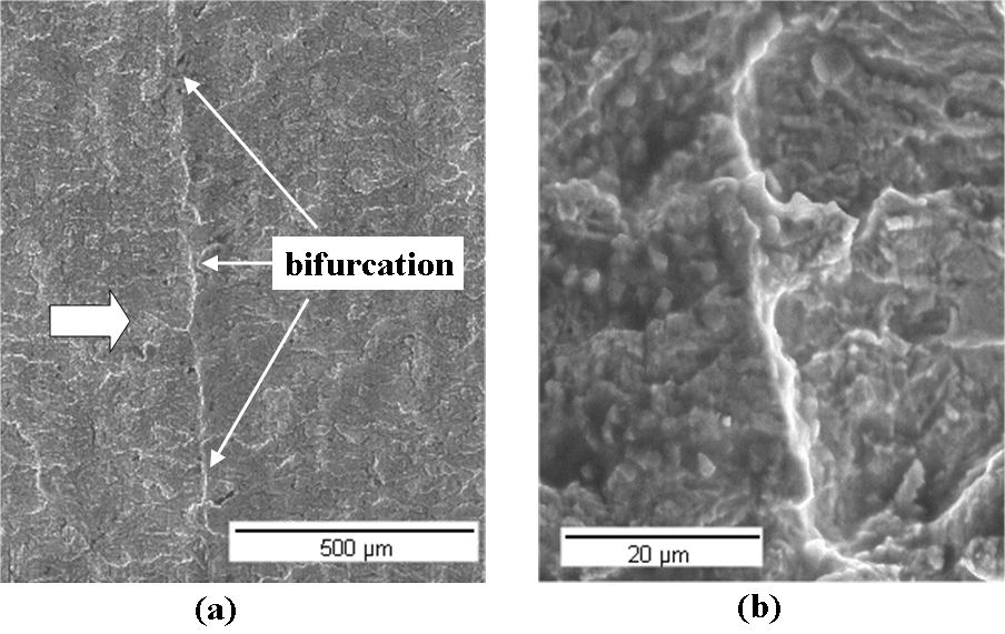
8 Figure 7: Scanning electron micrographs of fracture surfaces (test I): (a) bifurcation front through the specimen thickness, and (b) detailed view indicating different height levels. Figure 8: Scanning electron micrographs of fracture surfaces (test II): (a) bifurcation front through the specimen thickness, and (b) detailed view indicating different height levels. Figure 9: Scanning electron micrographs of fracture surfaces (test III): (a) bifurcation front through the specimen thickness, and (b) detailed view indicating different height levels.
.")

9 Figure 10: Crack bifurcation experiments on SAE 4340 steel (test IV): (a) front face of specimen (b) back face of specimen. Figure 11: Opening load measurements, before and after the overload (test IV). CONCLUSIONS In this work, a specialized FE program was used to calculate the propagation path and associated stress intensity factors (SIF) of bifurcated cracks, which can cause crack retardation or even arrest. In particular, the bifurcation simulations included several combinations of bifurcation angles 2θ = {40 o, 80 o, 90 o, 130 o, 168 o }, branch asymmetry ratios c 0 /b 0 = {0.5, 0.7, 0.8, 0.9, 0.95, 1.0}, crack growth exponents m = {2, 3, 4}, and even considered interaction between crack branching and other retardation mechanisms through the threshold ratios K PR /K I = {0.0, 0.067, 0.08, 0.10, 0.13, 0.20, 0.25, 0.40, 0.57}. The proposed equations, besides capturing all above described phenomena, can be readily used to predict the propagation behavior of branched and kinked cracks in an arbitrary structure, as long as the process zone ahead of the crack tip is small compared to the other characteristic dimensions, exactly as in other similar fatigue propagation problems such as curved crack path and life predictions.. However, these predictions probably should also be limited to the cases where it can be assumed that the entire crack-front bifurcates uniformly (as observed by scanning electron microscopy in the tests reported in this work), where the specimen thickness itself may provide the size scale requirements for the validity of the presented 2D LEFM-based equations, as the calculated SIF may be averaged considering the (several) grains present along the thickness. Otherwise, if the crack deflections vary significantly along the thickness, then 3D modeling including Mode III effects should be considered. From these results, it can be seen that crack bifurcation may provide an alternate
10 mechanistic explanation for overload-induced crack retardation on structural components, especially to explain load interaction effects under closure-free conditions. REFERENCES 1. Lankford J, Davidson DL. The Effect of Overloads upon Fatigue Crack Tip Opening Displacement and Crack Tip Opening/Closing Loads in Aluminum Alloys. Advances In Fracture Research, Pergamon Press 1981;2: Erdogan, F., Sih, G.C. On the Crack Extension in Plates under Plane Loading and Transverse Shear. Journal of Basic Engineering. 1963;85: Suresh S. Crack Deflection: Implications for the Growth of Long and Short Fatigue Cracks. Metallurgical Transactions 1983;14a: Karihaloo BL. On Crack Kinking and Curving. Mechanics of Materials 1982;1: Seelig T, Gross D. On the Interaction and Branching of Fast Running Cracks - A Numerical Investigation. Journal of the Mechanics and Physics of Solids 1999;47: Suresh S. Micromechanisms of Fatigue Crack Growth Retardation Following Overloads. Engineering Fracture Mechanics 1983;18(3): Suresh S. Fatigue of Materials. Cambridge University Press, 1998, 679p. 8. Melin S. Why do cracks avoid each other? International Journal of Fracture 1983;23: Pärletun LG. Determination of the growth of branched cracks by numerical methods. Engineering Fracture Mechanics 1979;11: Miranda ACO, Meggiolaro MA, Castro JTP, Martha LF, Bittencourt TN. Fatigue Crack Propagation under Complex Loading in Arbitrary 2D Geometries. ASTM STP 1411, 2002;4: Lang M, Marci G. The influence of single and multiple overloads on fatigue crack propagation. Fatigue and Fracture of Engineering Materials and Structures 1999;22: Sadananda K, Vasudevan AK, Holtz RL. Extension of the Unified Approach to Fatigue Crack Growth to Environmental Interactions. International Journal of Fatigue 2001;23:S277-S Sadananda K, Vasudevan AK. Fatigue Crack Growth Mechanisms in Steels. International Journal of Fatigue 2003;25: Miranda ACO, Meggiolaro MA, Castro JTP, Martha LF, Bittencourt TN. Fatigue Life and Crack Path Prediction in Generic 2D Structural Components. Eng. Fracture Mechanics 2003;70: ASTM Standard E 647. Standard Test Method for Measurement of Fatigue Crack Growth Rates. ASTM Standards; Paris P, Hermann L, Int.Cong. App. Mech., Delft, Castro JTP. A Circuit to Measure Crack Closure. Exp. Techniques 1993;17(2): Meggiolaro MA, Castro JTP. On the dominant role of crack closure on fatigue crack growth modeling. International Journal of Fatigue 2003;25(9-11):
Quantitative Evaluation of Fatigue Crack Growth Retardation Due to Crack Branching
 F004/6 Quantitative Evaluation of Fatigue Crack Growth Retardation Due to Crack Branching Marco Antonio Meggiolaro Mechanical Engineering Department Pontifical Catholic University of Rio de Janeiro (PUC-Rio),
Stress intensity factor equations for branched crack growth
 Engineering Fracture Mechanics 72 (2005) 2647 2671 www.elsevier.com/locate/engfracmech Stress intensity factor equations for branched crack growth M.A. Meggiolaro a, *, A.C.O. Miranda b, J.T.P. Castro
EVALUATION OF CRACK GROWTH RETARDATION IN BRANCHED FATIGUE CRACKS. Avaliação do Retardo de Crescimento por Fadiga de Trincas Bifurcadas
 doi: 10.4322/tmm.00101010 EVALUATION OF CRACK GROWTH RETARDATION IN BRANCHED FATIGUE CRACKS Marco Antonio Meggiolaro 1 Antonio Carlos de Oliveira Miranda 2 Jaime Tupiassú Pinho de Castro 3 Luiz Fernando
On the dominant role of crack closure on fatigue crack growth modeling
 International Journal of Fatigue 25 (2003) 843 854 www.elsevier.com/locate/ijfatigue On the dominant role of crack closure on fatigue crack growth modeling Marco Antonio Meggiolaro, Jaime Tupiassú Pinho
Fatigue life prediction of complex 2D components under mixed-mode variable amplitude loading
 International Journal of Fatigue 25 (2003) 1157 1167 www.elsevier.com/locate/ijfatigue Fatigue life prediction of complex 2D components under mixed-mode variable amplitude loading Antonio Carlos de Oliveira
Elastic-Plastic Fracture Mechanics. Professor S. Suresh
 Elastic-Plastic Fracture Mechanics Professor S. Suresh Elastic Plastic Fracture Previously, we have analyzed problems in which the plastic zone was small compared to the specimen dimensions (small scale
Stress Concentration. Professor Darrell F. Socie Darrell Socie, All Rights Reserved
 Stress Concentration Professor Darrell F. Socie 004-014 Darrell Socie, All Rights Reserved Outline 1. Stress Concentration. Notch Rules 3. Fatigue Notch Factor 4. Stress Intensity Factors for Notches 5.
A model to quantify fatigue crack growth by cyclic damage accumulation calculated by strip-yield procedures
 Focused on Crack Tip Fields A model to quantify fatigue crack growth by cyclic damage accumulation calculated by strip-yield procedures Samuel Elias Ferreira, Jaime Tupiassú Pinho de Castro, Marco Antonio
Load Sequence Interaction Effects in Structural Durability
 Load Sequence Interaction Effects in Structural Durability M. Vormwald 25. Oktober 200 Technische Universität Darmstadt Fachgebiet Werkstoffmechanik Introduction S, S [ log] S constant amplitude S variable
MMJ1133 FATIGUE AND FRACTURE MECHANICS E ENGINEERING FRACTURE MECHANICS
 E ENGINEERING WWII: Liberty ships Reprinted w/ permission from R.W. Hertzberg, "Deformation and Fracture Mechanics of Engineering Materials", (4th ed.) Fig. 7.1(b), p. 6, John Wiley and Sons, Inc., 1996.
Fracture Mechanics, Damage and Fatigue Non Linear Fracture Mechanics: J-Integral
 University of Liège Aerospace & Mechanical Engineering Fracture Mechanics, Damage and Fatigue Non Linear Fracture Mechanics: J-Integral Ludovic Noels Computational & Multiscale Mechanics of Materials CM3
A novel approach to predict the growth rate of short cracks under multiaxial loadings
 A novel approach to predict the growth rate of short cracks under multiaxial loadings F. Brugier 1&2, S. Pommier 1, R. de Moura Pinho 2, C. Mary 2 and D. Soria 2 1 LMT-Cachan, ENS Cachan / CNRS / UPMC
COMPARING OVERLOAD-INDUCED RETARDATION MODELS ON FATIGUE CRACK PROPAGATION
 COMPARING OVERLOAD-INDUCED RETARDATION MODELS ON FATIGUE CRACK PROPAGATION Marco Antonio Meggiolaro 1 Jaime Tupiassú Pinho de Castro 2 Summary The modeling of load interaction effects on mode I fatigue
PROPAGATION OF CURVED CRACKS IN HOMOGENEOUS AND GRADED MATERIALS
 PROPAGATION OF CURVED CRACKS IN HOMOGENEOUS AND GRADED MATERIALS Abstract Matthew T. Tilbrook, Robert J. Moon and Mark Hoffman School of Materials Science and Engineering University of New South Wales,
COMPARISON OF LOAD INTERACTION MODELS IN FATIGUE CRACK PROPAGATION
 XVI CONGRESSO BRASILEIRO DE ENGENHARIA MECÂNICA 16th BRAZILIAN CONGRESS OF MECHANICAL ENGINEERING COMPARISON OF LOAD INTERACTION MODELS IN FATIGUE CRACK PROPAGATION Marco Antonio Meggiolaro Pontifícia
IMPROVED ESTIMATES OF PLASTIC ZONES AROUND CRACK TIPS PART 1: THE EFFECTS OF THE T-STRESSES AND OF THE WESTERGAARD STRESS FUNCTION
 IMPROVED ESTIMATES OF PLASTIC ZONES AROUND CRACK TIPS PART 1: THE EFFECTS OF THE T-STRESSES AND OF THE WESTERGAARD STRESS FUNCTION Rafael Araujo de Sousa, rflsousa@tecgraf.puc-rio.br Tecgraf/PUC-Rio Grupo
Fracture mechanics fundamentals. Stress at a notch Stress at a crack Stress intensity factors Fracture mechanics based design
 Fracture mechanics fundamentals Stress at a notch Stress at a crack Stress intensity factors Fracture mechanics based design Failure modes Failure can occur in a number of modes: - plastic deformation
FATIGUE CRACK PROPAGATION UNDER VARIABLE AMPLITUDE LOADING ANALYSES BASED ON PLASTIC ENERGY APPROACH
 This work is licensed under the Creative Commons Attribution-NonCommercial-NoDerivs 3.0 Unported License. To view a copy of this license, visit http://creativecommons.org/licenses/by-nc-nd/3.0/ or send
Studies on the affect of Stress Triaxiality on Strain Energy Density, and CTOD under Plane Stress Condition Subjected to Mixed Mode (I/II) Fracture
 Fracture") Studies on the affect of Stress Triaxiality on Strain Energy Density, and CTOD under Plane Stress Condition... Studies on the affect of Stress Triaxiality on Strain Energy Density, and CTOD under Plane
Studies on the affect of Stress Triaxiality on Strain Energy Density, and CTOD under Plane Stress Condition... Studies on the affect of Stress Triaxiality on Strain Energy Density, and CTOD under Plane
Transactions on Modelling and Simulation vol 9, 1995 WIT Press, ISSN X
 Elastic-plastic model of crack growth under fatigue using the boundary element method M. Scibetta, O. Pensis LTAS Fracture Mechanics, University ofliege, B-4000 Liege, Belgium Abstract Life of mechanic
Experimental evaluation of plasticity-induced crack shielding from crack tip displacements fields
 Focussed on characterization of crack tip fields Experimental evaluation of plasticity-induced crack shielding from crack tip displacements fields J.M. Vasco-Olmo, F.A. Díaz University of Jaén, Departamento
A STUDY ON FATIGUE CRACK GROWTH IN CONCRETE IN THE PRE-PARIS REGION
 VIII International Conference on Fracture Mechanics of Concrete and Concrete Structures FraMCoS-8 J.G.M. Van Mier, G. Ruiz, C. Andrade, R.C. Yu and X.X. Zhang (Eds) A STUDY ON FATIGUE CRACK GROWTH IN CONCRETE
Size effect in the strength of concrete structures
 Sādhanā Vol. 27 Part 4 August 2002 pp. 449 459. Printed in India Size effect in the strength of concrete structures B L KARIHALOO and Q Z XIAO Division of Civil Engineering School of Engineering Cardiff
IMECE CRACK TUNNELING: EFFECT OF STRESS CONSTRAINT
 Proceedings of IMECE04 2004 ASME International Mechanical Engineering Congress November 13-20, 2004, Anaheim, California USA IMECE2004-60700 CRACK TUNNELING: EFFECT OF STRESS CONSTRAINT Jianzheng Zuo Department
Fracture Mechanics, Damage and Fatigue Linear Elastic Fracture Mechanics - Energetic Approach
 University of Liège Aerospace & Mechanical Engineering Fracture Mechanics, Damage and Fatigue Linear Elastic Fracture Mechanics - Energetic Approach Ludovic Noels Computational & Multiscale Mechanics of
Examination in Damage Mechanics and Life Analysis (TMHL61) LiTH Part 1
 LiTH Part 1") Part 1 1. (1p) Define the Kronecker delta and explain its use. The Kronecker delta δ ij is defined as δ ij = 0 if i j 1 if i = j and it is used in tensor equations to include (δ ij = 1) or "sort out" (δ
Part 1 1. (1p) Define the Kronecker delta and explain its use. The Kronecker delta δ ij is defined as δ ij = 0 if i j 1 if i = j and it is used in tensor equations to include (δ ij = 1) or "sort out" (δ
Siping Road 1239, , Shanghai, P.R. China
 COMPARISON BETWEEN LINEAR AND NON-LINEAR KINEMATIC HARDENING MODELS TO PREDICT THE MULTIAXIAL BAUSCHINGER EFFECT M.A. Meggiolaro 1), J.T.P. Castro 1), H. Wu 2) 1) Department of Mechanical Engineering,
MMJ1133 FATIGUE AND FRACTURE MECHANICS A - INTRODUCTION INTRODUCTION
 A - INTRODUCTION INTRODUCTION M.N.Tamin, CSMLab, UTM Course Content: A - INTRODUCTION Mechanical failure modes; Review of load and stress analysis equilibrium equations, complex stresses, stress transformation,
G1RT-CT A. BASIC CONCEPTS F. GUTIÉRREZ-SOLANA S. CICERO J.A. ALVAREZ R. LACALLE W P 6: TRAINING & EDUCATION
 A. BASIC CONCEPTS 6 INTRODUCTION The final fracture of structural components is associated with the presence of macro or microstructural defects that affect the stress state due to the loading conditions.
Critical applied stresses for a crack initiation from a sharp V-notch
 Focussed on: Fracture and Structural Integrity related Issues Critical applied stresses for a crack initiation from a sharp V-notch L. Náhlík, P. Hutař Institute of Physics of Materials, Academy of Sciences
FATIGUE DAMAGE ASSESMENT USING THERMOELASTIC STRESS ANALYSIS
 FATIGUE DAMAGE ASSESMENT USING THERMOELASTIC STRESS ANALYSIS F.A. Díaz, E.A. Patterson and J.R. Yates The University of Sheffield, Department of Mechanical Engineering, Mappin street, Sheffield S10 3JD,
Engineering Fracture Mechanics Prof. K. Ramesh Department of Applied Mechanics Indian Institute of Technology, Madras
 Engineering Fracture Mechanics Prof. K. Ramesh Department of Applied Mechanics Indian Institute of Technology, Madras Module No. # 07 Lecture No. # 34 Paris Law and Sigmoidal Curve (Refer Slide Time: 00:14)
Massachusetts Institute of Technology Department of Mechanical Engineering Cambridge, MA 02139
 Massachusetts Institute of Technology Department of Mechanical Engineering Cambridge, MA 02139 2.002 Mechanics and Materials II Spring 2004 Laboratory Module No. 6 Fracture Toughness Testing and Residual
CHAPTER 6 MECHANICAL PROPERTIES OF METALS PROBLEM SOLUTIONS
 CHAPTER 6 MECHANICAL PROPERTIES OF METALS PROBLEM SOLUTIONS Concepts of Stress and Strain 6.1 Using mechanics of materials principles (i.e., equations of mechanical equilibrium applied to a free-body diagram),
Determination of Dynamic Fracture Toughness Using Strain Measurement
 Key Engineering Materials Vols. 61-63 (4) pp. 313-318 online at http://www.scientific.net (4) Trans Tech Publications, Switzerland Online available since 4/4/15 Determination of Dynamic Fracture Toughness
NORMAL STRESS. The simplest form of stress is normal stress/direct stress, which is the stress perpendicular to the surface on which it acts.
 NORMAL STRESS The simplest form of stress is normal stress/direct stress, which is the stress perpendicular to the surface on which it acts. σ = force/area = P/A where σ = the normal stress P = the centric
Cohesive Zone Modeling of Dynamic Fracture: Adaptive Mesh Refinement and Coarsening
 Cohesive Zone Modeling of Dynamic Fracture: Adaptive Mesh Refinement and Coarsening Glaucio H. Paulino 1, Kyoungsoo Park 2, Waldemar Celes 3, Rodrigo Espinha 3 1 Department of Civil and Environmental Engineering
Fig. 1. Different locus of failure and crack trajectories observed in mode I testing of adhesively bonded double cantilever beam (DCB) specimens.
 specimens.") a). Cohesive Failure b). Interfacial Failure c). Oscillatory Failure d). Alternating Failure Fig. 1. Different locus of failure and crack trajectories observed in mode I testing of adhesively bonded double
a). Cohesive Failure b). Interfacial Failure c). Oscillatory Failure d). Alternating Failure Fig. 1. Different locus of failure and crack trajectories observed in mode I testing of adhesively bonded double
Stress concentrations, fracture and fatigue
 Stress concentrations, fracture and fatigue Piet Schreurs Department of Mechanical Engineering Eindhoven University of Technology http://www.mate.tue.nl/ piet December 1, 2016 Overview Stress concentrations
CRACK-TIP DRIVING FORCE The model evaluates the eect of inhomogeneities by nding the dierence between the J-integral on two contours - one close to th
 ICF 100244OR Inhomogeneity eects on crack growth N. K. Simha 1,F.D.Fischer 2 &O.Kolednik 3 1 Department ofmechanical Engineering, University of Miami, P.O. Box 248294, Coral Gables, FL 33124-0624, USA
An Evaluation of Elber-Type Crack Retardation Models
 Copyright 001 Society of Automotive Engineers, Inc 001-01-4063 An Evaluation of Elber-Type Crack Retardation Models Marco Antonio Meggiolaro Jaime Tupiassú Pinho de Castro Mechanical Engineering Department
MICROMECHANICAL MODELS FOR CONCRETE
 Chapter 5 MICROMECHANICAL MODELS FOR CONCRETE 5.1 INTRODUCTION In this chapter three micromechanical models will be examined. The first two models are the differential scheme and the Mori-Tanaka model
G1RT-CT D. EXAMPLES F. GUTIÉRREZ-SOLANA S. CICERO J.A. ALVAREZ R. LACALLE W P 6: TRAINING & EDUCATION
 D. EXAMPLES 426 WORKED EXAMPLE I Flat Plate Under Constant Load Introduction and objectives Data Analysis Bibliography/References 427 INTRODUCTION AND OBJECTIVES During a visual inspection of a C-Mn flat
Mechanical properties 1 Elastic behaviour of materials
 MME131: Lecture 13 Mechanical properties 1 Elastic behaviour of materials A. K. M. B. Rashid Professor, Department of MME BUET, Dhaka Today s Topics Deformation of material under the action of a mechanical
Stress-Strain Behavior
 Stress-Strain Behavior 6.3 A specimen of aluminum having a rectangular cross section 10 mm 1.7 mm (0.4 in. 0.5 in.) is pulled in tension with 35,500 N (8000 lb f ) force, producing only elastic deformation.
VERIFICATION OF BRITTLE FRACTURE CRITERIA FOR BIMATERIAL STRUCTURES
 VERIFICATION OF BRITTLE FRACTURE CRITERIA FOR BIMATERIAL STRUCTURES Grzegorz MIECZKOWSKI *, Krzysztof MOLSKI * * Faculty of Mechanical Engineering, Białystok University of Technology, ul. Wiejska 45C,
CHAPTER 9 FAILURE PROBLEM SOLUTIONS
 Excerpts from this work may be reproduced by instructors for distribution on a not-for-profit basis for testing or instructional purposes only to students enrolled in courses for which the textbook has
TENSILE FATIGUE BEHAVIOR OF SINGLE FIBRES AND FIBRE BUNDLES
 TENSILE FATIGUE BEHAVIOR OF SINGLE FIBRES AND FIBRE BUNDLES C. Qian 1 *, R. P. L. Nijssen 1, D. D. Samborsky 2, C.Kassapoglou 3, Z. Gürdal 3, G. Q. Zhang 4 1 Knowledge Centre Wind turbine Materials and
Life Prediction Under Multiaxial Fatigue
 Lie Prediction Under Multiaxial Fatigue D. Ramesh and M.M. Mayuram Department o Mechanical Engineering Indian Institute o Technology, Madras Chennai-600 036 (India) e-mail: mayuram@iitm.ac.in ABSTRACT
Tentamen/Examination TMHL61
 Avd Hållfasthetslära, IKP, Linköpings Universitet Tentamen/Examination TMHL61 Tentamen i Skademekanik och livslängdsanalys TMHL61 lördagen den 14/10 2000, kl 8-12 Solid Mechanics, IKP, Linköping University
E ect of stress ratio and specimen thickness on fatigue crack growth of CK45 steel
 Theoretical and Applied Fracture Mechanics 30 (1998) 65±73 E ect of stress ratio and specimen thickness on fatigue crack growth of CK45 steel J.D.M. Costa *, J.A.M. Ferreira Department of Mechanical Engineering,
A Crack Growth Rate Conversion Module: Theory, Development, User Guide and Examples
 A Crack Growth Rate Conversion Module: Theory, Development, User Guide and Examples Yu Chee Tong, Weiping Hu and David Mongru Air Vehicles Division Defence Science and Technology Organisation DSTO-TR-2050
Available online at ScienceDirect. 20th European Conference on Fracture (ECF20) Yu.G. Matvienko*
 Yu.G. Matvienko*") Available online at www.sciencedirect.com ScienceDirect Procedia Materials Science 3 ( 014 ) 141 146 0th European Conference on Fracture (ECF0) The Effect of the non-singular T-stress components on crack
Available online at www.sciencedirect.com ScienceDirect Procedia Materials Science 3 ( 014 ) 141 146 0th European Conference on Fracture (ECF0) The Effect of the non-singular T-stress components on crack
Lecture #2: Split Hopkinson Bar Systems
 Lecture #2: Split Hopkinson Bar Systems by Dirk Mohr ETH Zurich, Department of Mechanical and Process Engineering, Chair of Computational Modeling of Materials in Manufacturing 2015 1 1 1 Uniaxial Compression
Specimen Geometry and Material Property Uncertainty Model for Probabilistic Fatigue Life Predictions
 Specimen Geometry and Material Property Uncertainty Model for Probabilistic Fatigue Life Predictions Prakash Chandra Gope*, Sandeep Bhatt**, and Mohit Pant** *Associate Professor, Mechanical Engineering
THE THRESHOLD STRESS INTENSITY RANGE IN FATIGUE
 Fatigue ofengineering Materials and Structures Vol. 1, pp. 151-158 Perpmon Press. Printed in Great Britain. Fatigue of Engineering Materials Ltd. 1979. THE THRESHOLD STRESS INTENSITY RANGE IN FATIGUE R.
COMPARISON OF FATIGUE CRACK GROWTH CONCEPTS WITH RESPECT TO INTERACTION EFFECTS
 COMPARISON OF FATIGUE CRAC GROWTH CONCEPTS WITH RESPECT TO INTERACTION EFFECTS M. Sander University of Paderborn, Institute of Applied Mechanics Pohlweg 47-49, D-3398 Paderborn, Germany sander@fam.upb.de
EMA 3702 Mechanics & Materials Science (Mechanics of Materials) Chapter 2 Stress & Strain - Axial Loading
 Chapter 2 Stress & Strain - Axial Loading") MA 3702 Mechanics & Materials Science (Mechanics of Materials) Chapter 2 Stress & Strain - Axial Loading MA 3702 Mechanics & Materials Science Zhe Cheng (2018) 2 Stress & Strain - Axial Loading Statics
MA 3702 Mechanics & Materials Science (Mechanics of Materials) Chapter 2 Stress & Strain - Axial Loading MA 3702 Mechanics & Materials Science Zhe Cheng (2018) 2 Stress & Strain - Axial Loading Statics
Volume 2 Fatigue Theory Reference Manual
 Volume Fatigue Theory Reference Manual Contents 1 Introduction to fatigue 1.1 Introduction... 1-1 1. Description of the applied loading... 1-1.3 Endurance curves... 1-3 1.4 Generalising fatigue data...
Transactions on Engineering Sciences vol 6, 1994 WIT Press, ISSN
 The treatment of crack propagation in inhomogeneous materials using the boundary element method A. Boussekine," L. Ulmet," S. Caperaa* " Laboratoire de Genie Civil, Universite de Limoges, 19300 Egletons,
Derivation of Paris Law Parameters from S-N Curve Data: a Bayesian Approach
 Derivation of Paris Law Parameters from S-N Curve Data: a Bayesian Approach Sreehari Ramachandra Prabhu 1) and *Young-Joo Lee 2) 1), 2) School of Urban and Environmental Engineering, Ulsan National Institute
Waveform Parameters. Correlation of Count Rate and Material Properties. Emission Hits and Count. Acoustic Emission Event Energy
 Cumulative representations of these parameters can be defined as a function of time or test parameter (such as pressure or temperature), including: () total hits, (2) amplitude distribution and (3) accumulated
EXTRAPOLATION ALGORITHMS AND OVERLOAD EFFECTS IN HIGH CYCLE FATIGUE
 EXTRAPOLATION ALGORITHMS AND OVERLOAD EFFECTS IN HIGH CYCLE FATIGUE A Thesis Presented to the Faculty of the Graduate School of Cornell University in Partial Fulfillment of the Requirements for the Degree
Discrete Element Modelling of a Reinforced Concrete Structure
 Discrete Element Modelling of a Reinforced Concrete Structure S. Hentz, L. Daudeville, F.-V. Donzé Laboratoire Sols, Solides, Structures, Domaine Universitaire, BP 38041 Grenoble Cedex 9 France sebastian.hentz@inpg.fr
Laboratory 4 Bending Test of Materials
 Department of Materials and Metallurgical Engineering Bangladesh University of Engineering Technology, Dhaka MME 222 Materials Testing Sessional.50 Credits Laboratory 4 Bending Test of Materials. Objective
SEMI-CIRCULAR BENDING TEST TO ASSESS THE RESISTANCE AGAINST CRACK GROWTH
 Performance Testing and Evaluation of Bituminous Materials 257 SEMI-CIRCULAR BENDING TEST TO ASSESS THE RESISTANCE AGAINST CRACK GROWTH R. Hofman, B. Oosterbaan, S.M.J.G. Erkens and Jo van der Kooij Road
SKIN-STRINGER DEBONDING AND DELAMINATION ANALYSIS IN COMPOSITE STIFFENED SHELLS
 SKIN-STRINER DEBONDIN AND DELAMINATION ANALYSIS IN COMPOSITE STIFFENED SHELLS R. Rikards, K. Kalnins & O. Ozolinsh Institute of Materials and Structures, Riga Technical University, Riga 1658, Latvia ABSTRACT
Lecture #7: Basic Notions of Fracture Mechanics Ductile Fracture
 Lecture #7: Basic Notions of Fracture Mechanics Ductile Fracture by Dirk Mohr ETH Zurich, Department of Mechanical and Process Engineering, Chair of Computational Modeling of Materials in Manufacturing
Finite element analysis of diagonal tension failure in RC beams
 Finite element analysis of diagonal tension failure in RC beams T. Hasegawa Institute of Technology, Shimizu Corporation, Tokyo, Japan ABSTRACT: Finite element analysis of diagonal tension failure in a
Minimum principles for characterizing the trajectories and microstructural evolution of dissipative systems
 Minimum principles for characterizing the trajectories and microstructural evolution of dissipative systems M. Ortiz California Institute of Technology In collaboration with: S. Conti, C. Larsen, A. Mielke,
The Effects of Transverse Shear on the Delamination of Edge-Notch Flexure and 3-Point Bend Geometries
 The Effects of Transverse Shear on the Delamination of Edge-Notch Flexure and 3-Point Bend Geometries M. D. Thouless Department of Mechanical Engineering Department of Materials Science & Engineering University
Evolution of Tenacity in Mixed Mode Fracture Volumetric Approach
 Mechanics and Mechanical Engineering Vol. 22, No. 4 (2018) 931 938 c Technical University of Lodz Evolution of Tenacity in Mixed Mode Fracture Volumetric Approach O. Zebri LIDRA Laboratory, Research team
CHARACTERIZATION, ANALYSIS AND PREDICTION OF DELAMINATION IN COMPOSITES USING FRACTURE MECHANICS
 Oral Reference Number: ICF100942OR CHARACTERIZATION, ANALYSIS AND PREDICTION OF DELAMINATION IN COMPOSITES USING FRACTURE MECHANICS T. Kevin O Brien U.S. Army Research Laboratory Vehicle Technology Directorate
Mechanics of Earthquakes and Faulting
 Mechanics of Earthquakes and Faulting Lectures & 3, 9/31 Aug 017 www.geosc.psu.edu/courses/geosc508 Discussion of Handin, JGR, 1969 and Chapter 1 Scholz, 00. Stress analysis and Mohr Circles Coulomb Failure
INFLUENCE OF THE LOCATION AND CRACK ANGLE ON THE MAGNITUDE OF STRESS INTENSITY FACTORS MODE I AND II UNDER UNIAXIAL TENSION STRESSES
 INFLUENCE OF THE LOCATION AND CRACK ANGLE ON THE MAGNITUDE OF STRESS INTENSITY FACTORS MODE I AND II UNDER UNIAXIAL TENSION STRESSES Najah Rustum Mohsin Southern Technical University, Technical Institute-Nasiriya,
Numerical Characterization of Concrete Heterogeneity
 Vol. Materials 5, No. Research, 3, 2002Vol. 5, No. 3, Statistical 309-314, 2002. Characterization of the Concrete Numerical Modeling of Size Effect In Heterogeneity 2002 309 Numerical Characterization
V-notched elements under mode II loading conditions
 Structural Engineering and Mechanics, Vol. 49, No. 4 (2014) 499-508 DOI: http://dx.doi.org/10.12989/sem.2014.49.4.499 499 V-notched elements under mode loading conditions Alberto Sapora, Pietro Cornetti
Observation of Magnetic Flux Density Distribution around Fatigue Crack and Application to Non-Destructive Evaluation of Stress Intensity Factor
 Available online at www.sciencedirect.com Procedia Engineering 10 (2011) 881 886 ICM11 Observation of Magnetic Flux Density Distribution around Fatigue Crack and Application to Non-Destructive Evaluation
Non-linear fracture mechanics in LS-DYNA and LS-PrePost
 Non-linear fracture mechanics in LS-DYNA and LS-PrePost Per Lindström 1,, Anders Jonsson 3, Anders Jernberg 3, Erling Østby 1 Department of Engineering Science, University West, Trollhättan, Sweden DNV
Low-Cycle Fatigue Crack Growth in Ti-6242 at Elevated Temperature Rebecka Brommesson 1,a, Magnus Hörnqvist,2,b, and Magnus Ekh 3,c
 Low-Cycle Fatigue Crack Growth in Ti-6242 at Elevated Temperature Rebecka Brommesson 1,a, Magnus Hörnqvist,2,b, and Magnus Ekh 3,c 1,3 Department of Applied Mechanics, Chalmers University of Technology,
Analysis of asymmetric radial deformation in pipe with local wall thinning under internal pressure using strain energy method
 Analysis of asymmetric radial deformation in pipe with local wall thinning under internal pressure using strain energy method V.M.F. Nascimento Departameto de ngenharia Mecânica TM, UFF, Rio de Janeiro
Crack Tip Plastic Zone under Mode I Loading and the Non-singular T zz -stress
 Crack Tip Plastic Zone under Mode Loading and the Non-singular T -stress Yu.G. Matvienko Mechanical Engineering Research nstitute of the Russian Academy of Sciences Email: ygmatvienko@gmail.com Abstract:
A FINITE ELEMENT MODEL FOR SIZE EFFECT AND HETEROGENEITY IN CONCRETE STRUCTURES
 A FINITE ELEMENT MODEL FOR SIZE EFFECT AND HETEROGENEITY IN CONCRETE STRUCTURES Roque Luiz Pitangueira 1 and Raul Rosas e Silva 2 1 Department of Structural Engineering -Federal University of Minas Gerais
DAMAGE MECHANICS MODEL FOR OFF-AXIS FATIGUE BEHAVIOR OF UNIDIRECTIONAL CARBON FIBER-REINFORCED COMPOSITES AT ROOM AND HIGH TEMPERATURES
 DAMAGE MECHANICS MODEL FOR OFF-AXIS FATIGUE BEHAVIOR OF UNIDIRECTIONAL CARBON FIBER-REINFORCED COMPOSITES AT ROOM AND HIGH TEMPERATURES M. Kawai Institute of Engineering Mechanics University of Tsukuba,
FATIGUE DAMAGE PROGRESSION IN PLASTICS DURING CYCLIC BALL INDENTATION
 FATIGUE DAMAGE PROGRESSION IN PLASTICS DURING CYCLIC BALL INDENTATION AKIO YONEZU, TAKAYASU HIRAKAWA, TAKESHI OGAWA and MIKIO TAKEMOTO Department of Mechanical Engineering, College of Science and Engineering,
DETERMINATION OF STRESS INTENSITY FACTORS ALONG CRACKED SURFACES IN PIPING ELBOWS STRUCTURES E.M.M.FONSECA*, F.Q.MELO**, R.A.F.
 1 th PORTUGUESE CONFERENCE ON FRACTURE - 6 DETERMINATION OF STRESS INTENSITY FACTORS ALONG CRACKED SURFACES IN PIPING ELBOWS STRUCTURES E.M.M.FONSECA*, F.Q.MELO**, R.A.F.VALENTE** *CENUME IDMEC Instituto
V Predicted Weldment Fatigue Behavior AM 11/03 1
 V Predicted Weldment Fatigue Behavior AM 11/03 1 Outline Heavy and Light Industry weldments The IP model Some predictions of the IP model AM 11/03 2 Heavy industry AM 11/03 3 Heavy industry AM 11/03 4
Transactions on Engineering Sciences vol 6, 1994 WIT Press, ISSN
 Strain energy release rate calculation from 3-D singularity finite elements M.M. Abdel Wahab, G. de Roeck Department of Civil Engineering, Katholieke Universiteit, Leuven, B-3001 Heverlee, Belgium ABSTRACT
Archetype-Blending Multiscale Continuum Method
 Archetype-Blending Multiscale Continuum Method John A. Moore Professor Wing Kam Liu Northwestern University Mechanical Engineering 3/27/2014 1 1 Outline Background and Motivation Archetype-Blending Continuum
Stress intensity factors for an inclined and/or eccentric crack in a finite orthotropic lamina
 1886 Stress intensity factors for an inclined and/or eccentric crack in a finite orthotropic lamina Abstract Stress intensity factors (SIF) are determined for an inclined and / or eccentric crack in a
Fatigue Life Prediction Based on the Advanced Fatigue Crack Growth Model and the Monte-Carlo Simulation Method
 Fatigue Life Prediction Based on the Advanced Fatigue Crack Growth Model and the Monte-Carlo Simulation Method by Sergey Bogdanov A thesis presented to the University of Waterloo in fulfillment of the
Available online at ScienceDirect. 5th Fatigue Design Conference, Fatigue Design 2013
 Available online at www.sciencedirect.com ScienceDirect Procedia Engineering 66 ( 2013 ) 626 634 5th Fatigue Design Conference, Fatigue Design 2013 Fatigue Damage Analysis on Aluminium Alloy Specimens
Transactions on Engineering Sciences vol 6, 1994 WIT Press, ISSN
 Significance of the characteristic length for micromechanical modelling of ductile fracture D.-Z. Sun, A. Honig Fraunhofer-Institut fur Werkstoffmechanik, Wohlerstr. 11, D-79108 Freiburg, Germany ABSTRACT
Frontiers of Fracture Mechanics. Adhesion and Interfacial Fracture Contact Damage
 Frontiers of Fracture Mechanics Adhesion and Interfacial Fracture Contact Damage Biology, Medicine & Dentistry The Next Frontiers For Mechanics One of the current challenges in materials & mechanics is
Cracked concrete structures under cyclic load
 Cracked concrete structures under cyclic load Fabrizio Barpi & Silvio Valente Department of Structural and Geotechnical Engineering, Politecnico di Torino, Torino, Italy ABSTRACT: The safety of cracked
Determination of dynamic fracture toughness using a new experimental technique
 EPJ Web of Conferences 94, 01012 (2015) DOI: 10.1051/epjconf/20159401012 c Owned by the authors, published by EDP Sciences, 2015 Determination of dynamic fracture toughness using a new experimental technique
XFEM-based cycle-by-cycle simulation of fatigue crack growth. Louis Muys
 XFEM-based cycle-by-cycle simulation of fatigue crack growth Louis Muys Supervisors: Prof. dr. ir. Wim De Waele, Prof. Stijn Hertelé Counsellor: Jie Zhang Master's dissertation submitted in order to obtain
MECHANICS OF MATERIALS
 CHATR Stress MCHANICS OF MATRIALS and Strain Axial Loading Stress & Strain: Axial Loading Suitability of a structure or machine may depend on the deformations in the structure as well as the stresses induced
Constitutive Equations (Linear Elasticity)
") Constitutive quations (Linear lasticity) quations that characterize the physical properties of the material of a system are called constitutive equations. It is possible to find the applied stresses knowing
Constitutive quations (Linear lasticity) quations that characterize the physical properties of the material of a system are called constitutive equations. It is possible to find the applied stresses knowing
The science of elasticity
 The science of elasticity In 1676 Hooke realized that 1.Every kind of solid changes shape when a mechanical force acts on it. 2.It is this change of shape which enables the solid to supply the reaction