Granite rock fragmentation at percussive drilling - experimental and numerical investigation
|
|
|
- Edwin Harvey
- 6 years ago
- Views:
Transcription
1 Granite rock fragmentation at percussive drilling - experimental and numerical investigation M. Saadati a,b, P. Forquin c, K. Weddfelt b, P.L. Larsson a,*, F. Hild d a Department of Solid Mechanics, KTH Royal Institute of Technology, Stockholm, Sweden b Atlas Copco, Örebro, Sweden c 3SR Lab., Joseph Fourier University, Grenoble, France d LMT Cachan, ENS Cachan / CNRS / UPMC / PRES UniverSud Paris, Cachan, France Abstract The aim of this study is to numerically model the fracture system at percussive drilling. Due to the complex behavior of rock materials, a continuum approach is employed relying upon a plasticity model with yield surface locus as a quadratic function of the mean pressure in the principal stress space coupled with an anisotropic damage model. In particular, Bohus granite rock is investigated and the material parameters are defined based on previous experiments. This includes different tests such as direct tension and compression, three point bending and quasi-oedometric tests to investigate the material behavior at both tension and confined compression stress states. The equation of motion is discretized using a FE approach and the explicit time integration method is employed. EOI (Edge-On Impact) tests are performed and the results are used to validate the numerical model. The percussive drilling problem is then modeled in 3D and the bit-rock interaction is considered using contact mechanics. The fracture mechanism in the rock and the bit penetration- resisting force response are realistically captured by the numerical model. Keywords: Granite, percussive drilling, KST-DFH model, fragmentation * Corresponding author address: plla@kth.se 1
2 1 Introduction Rock drilling has been extensively used in the mining industry for many decades. A sound understanding of bit-rock interaction and rock fragmentation mechanisms is essential to optimize the drilling process. The percussive drilling method is commonly used in the tunneling and mining business. The main idea is that a piston hits the drill rod at a velocity of about 10 m/s. This creates a compressive stress wave with an amplitude of about 200 MPa, which propagates along the drill rod. The stress wave is then transferred into the rock through the tool buttons. Each tool includes around ten buttons made of hard steel that facilitate the indentation process. Unlike the situation of quasi-static indentation, the stress waves and rapid indentation make percussive drilling a transient dynamic problem with high local strain rates in the rock [1]. Basic defects in rocks are voids, pores and microcracks as well as other related features [2]. Such microstructures produce heterogeneity in the strength and stiffness of the material. It is well known that rock fractures via initiation, growth and coalescence of microcracks, together with sliding between individual grains and the microcrack surfaces. Associated with these microscopic mechanisms, rock specimens exhibit non-linear stress-strain responses [2]. Granite, which is the material studied in this work, has many pre-existing cracks, (e.g. [3] and [4]), but the porosity is very low (about 0.2%). Most rocks show a transition from brittle to ductile behavior by increasing the confined pressure [2]. However, silicate rocks with low porosity are brittle at room temperature over the whole range of normal laboratory confining pressures up to GPa. Some workers have reported that granite exhibits brittle fracture behavior even at confining pressures up to 3-4 GPa [5]. Many studies have been performed during the past years to numerically simulate rock drilling and the fragmentation process in brittle materials. Liu [6] developed a rock and tool interaction code (R-T 2D ) and studied the fragmentation process in a quasi-static situation. Wang et al. [7] used an in-house numerical tool to simulate the rock fragmentation process induced by indentation. Both Liu and Wang et al. restrict their analyses to 2D plain strain conditions and do not account for inelastic strains. Furthermore, Saksala [8,9] studied the impact indentation of rocks using an isotropic damage concept for tensile loading and a viscoplasticity consistency model for compression loading. This work is performed under 2D plane strain conditions. More recently, the model was extended to deal with 3D simulations [10]. Chiang et al. [11] modeled the impact of tool to the rock and rock fragmentation in drilling process using a 3D FE approach. A linear Mohr envelop together with a tension cut off plane is employed as a criterion for maximum strength of rock. The material behavior is considered linear elastic before reaching the final failure. Additionally, Thuro et al. [12] used Particle Flow Code (PFC 2D ) to investigate the crack pattern in drilling and its correlation with existing foliations. PFC 2D code is based on discontinuum mechanics approach and is built for 2D simulations. Forquin and Hild [13] studied dynamic fragmentation in brittle materials in general due to impact loading by using a probabilistic approach to describe the material behavior. The constitutive equation consists of the plasticity model introduced by Krieg [14], Swenson and Taylor [15] for compressive loadings and coupled with the anisotropic damage model developed by Denoual and Hild [16], Forquin and Hild [13], in tension (here and in the sequel referred to as the KST-DFH model). It is shown how a brittle and 2
3 random behavior under quasi-static tensile loading becomes deterministic and stress-rate dependent when increasing the loading rate. This type of model was able to describe the fragmentation of two grades of limestone subjected to EOI tests [17] and the enhancement of strength and failure pattern of a microconcrete [18] and a standard concrete [19] in spalling tests and EOI experiments. In this investigation, the KST-DFH model is selected as the constitutive model based on the findings in a previous study by Saadati et al [20]. This model is a good alternative as it deals with both dynamic fragmentation due to tensile stress waves and also plasticity-like deformation in compression. This is very similar to the situation at percussive drilling as the impact of the piston induces stress waves into the rock and initiate tensile cracks, while high compressive stresses prevail beneath the indenter and lead to crushing of the rock. The KST-DFH model parameters for Bohus granite are defined based on previously reported experimental results [20]. Edge-On Impact (EOI) tests, i.e. impact of an aluminum projectile onto a rock slab [21], are performed. The tests are numerically modeled and these results are compared to the experimental data to validate the constitutive model. After that, the numerical tool is used to simulate the percussive drilling problem and the results are compared with real drilling data. 2 Constitutive specification 2.1 KST model The KST model has been developed to simulate the compressive behavior of geomaterials accounting for the effect of hydrostatic and deviatoric parts of the stress tensor [14,15]. In the deviatoric part, the locus of the yield surface is a quadratic function of the mean pressure in the principal stress space. 2 eq a0 a1p a2p (1) where σ eq is the equivalent (von Mises) stress, P the hydrostatic stress, a 0, a 1 and a 2 are material dependent coefficients. Furthermore, the model includes a piece-wise linear equation of state linking the volumetric strain, ε v, to the hydrostatic stress. At the first stage of hydrostatic loading, the material behaves elastically. By increasing the pressure, collapse of pores occurs in the case of porous rocks, which is modeled by an irreversible volumetric strain. During the porosity breakage, the bulk modulus, K, decreases noticeably. When all pores are closed, the material exhibits a higher bulk modulus which corresponds to the compacted material [22]. However, granite exhibits constant bulk modulus in the whole hydrostatic stress range as it includes a very small amount of porosity [20]. 2.2 The DFH fragmentation model The DFH fragmentation model is explained in detail in Refs. [13] and [16]. In the sequel a brief summary of the model including both single and multiple fragmentation regimes is presented Single fragmentation Under low loading rate conditions, the fracture process is generally the consequence of the initiation and growth of a single crack. When the stress increases, the weakest defect is first activated. An unstable crack is initiated and propagates very quickly leading to fracture of the whole structure. 3
4 Defects with different sizes and orientations are randomly distributed within the material and consequently the failure stress is random. To model this tensile behavior, a probabilistic approach may be employed. Using a Poisson point-process framework, the weakest link theory and Weibull model, the failure probability P F is given by [23,24] P 1 exp[ Z ( )] (2) F eff t F where Z eff is the effective volume [25], and λ t is the initiation density defined by F t( F) 0 S0 m (3) m where m is the Weibull modulus, S / 0 0 is the Weibull scale parameter, and σ F the maximum principal stress in the whole domain. The effective volume, Z eff, is expressed as Z eff ZH (4) m where Z is the size of the whole volume, and H m the stress heterogeneity factor [26] written as H m 1 Z m 1 dz when F 0 (5) F where σ 1 is the local maximum principal stress, and Macauley s brackets. The stress heterogeneity factor characterizes the effect of the load pattern on the cumulative failure probability. Last, the average failure stress σ w and the corresponding standard deviation σ sd are written as and 1/ m 1 w S0( 0ZH m) 1 m (6) sd 1/ m S0( 0ZH m) 1 1 m m (7) where Г is the Euler function of the second kind 1 x exp( u) u x du (8) 0 To characterize specific materials, 3-point bend tests are performed and the distribution of the failure stresses is obtained. One classical way to obtain the Weibull modulus m is then to look at the slope of linear interpolation in the diagram of ln[-ln(1-p F )] versus ln(σ F ) or the modified Weibull plot [20]. The m scale parameter S / 0 0 can then be extracted from Eqs. (6) and (8), or the intercept in the Weibull plot. 4
5 2.2.2 Multiple fragmentation Under high strain-rate conditions, several cracks are initiated and propagate from the initial defects leading to multiple fragmentation. The initial defects are assumed to be randomly distributed and activated for a random level of stress. When a crack is initiated, it propagates at a very high velocity (a portion of the stress wave velocity) and relaxes the stresses in its vicinity. This prevents activation of new defects in an obscured zone centered on this crack. At the same time the stress is increasing in the non-obscured zone and new critical defects are activated leading to new crack openings [13,16]. Therefore, dynamic fragmentation corresponds to a competition between, on the one hand, new critical defects that progressively initiate cracks with the increase of the stress level and, on the other hand, obscuration of areas of potential critical defects by cracks created before. The fragmentation process ends when the whole domain is obscured by the propagating cracks. The interaction law between cracks already initiated and the critical defects of the material is given by the concept of probability of non-obscuration [16]. If the initiation density is a continuous function, the probability of non-obscuration of point M at time T in a domain Ω is described by [13] t ( xt, ) Pno( M, T) exp dvdt (9) t ( x, t) [ horizon of ( M, T )] where the horizon is defined by n horizon of ( M, T) x, t [ Z ( T t) S( kc( T t)) ]. (10) o In Eq. (10), Z o is the obscured zone, k a constant parameter (k = 0.38 when the crack length becomes significantly larger than the initial size), C the 1D wave speed, T the current time and t the crack initiation time, S a shape parameter (equal to 4π/3 when the obscuration volume is similar to a sphere in 3D) and n the medium dimension (n = 3 in 3D). The single fragmentation process occurs at quasi-static conditions and the probability of obscuration P o = 1P no P F corresponds to the failure probability, Eq.(2), expressed by Weibull s model. Therefore the initiation density for dynamic fragmentation (see Eq. (9)) is identical to that used in the analysis of quasi-static cases as described in Eq. (3). In the case of multiple fragmentation, the interaction between the horizon and the boundary of the domain Ω is small and if a uniform stress field is assumed, the obscuration probability in multiple fragmentation is written as [16] T d Po ( T) 1 Pno ( T) 1 exp t [ ( t)] Zo( T t) dt 0 dt (11) 5
6 The non-obscuration probability provides an indication for the fraction of initiated cracks that correspond to the critical defects activated in the non-obscured volumes. The increment of the crack density cracks is associated with the obscuration probability and the increment of initiation density cracks P t (12) no dt dt Eq. (12) expresses the fact that cracks will initiate only if a defect exists in a non-obscured zone of the volume. The probability of obscuration is defined for each principal direction i and the evolution of P i is expressed in a differential form in order to be employed in a FE code using Eq. (11) d dt 2 1 dpi 3 di 2 S kc0 t i t when and i 1 Pi dt dt 3! [ ( )] 0 0 (13) where σ i is the local principal stress component. The KST-DFH model is also combined with a cohesive model in order to describe the cohesive strength in the obscured zone and the softening behavior of geomaterials in dynamic tension [27]. In the cohesive model, an extra term is added to the macroscopic stress i as (1 P) ( P) D ( ) (1 D ) (14) i i i i coh i i where is the residual strength in the obscuration zone n d d coh o exp d (15) 0 where α D,,, n d are material-dependent parameters, and D i the damage variable defined for each principal direction. The cohesive term can be seen as an extra contribution related to the fracture energy of the material. It enforces the final failure of an element to occur when the dissipated energy due to the damage process reaches the fracture energy of the material. In the principal stress frame, the compliance tensor is defined by 1 1 D E 1 D D3 (16) where ε 1, ε 2, ε 3 are the principal strains, E Young s modulus and ν Poisson s ratio of the undamaged material. At the inception of damage growth, the principal damage frame coincides with the principal 6
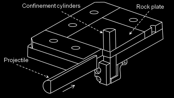
7 stress tensor frame and the eigen directions may change at each time step until the first damage variable D 1 reaches a threshold value of 0.2. Then the direction of D 1 is locked and the other directions D 2, and D 3 follow the eigen directions with the constraint to be perpendicular to D 1. When the second damage variable reaches the threshold value, the whole directions are locked. 3 The material model parameters The KST-DFH model parameters for Bohus granite, see Table legends Table 1, are obtained based on previous experimental work [20]. In Table legends Table 1, the mechanical properties (E and ν) are determined from direct tensile and compression tests while the DFH model parameters are obtained mainly from flexural experiments. The KST model is calibrated based on quasi-oedometric test results, see Figure legends Fig. 1, and in particular the experimental data at high levels of hydrostatic pressure for which there is a considerable amount of inelastic strains (as the specimen mainly deforms elastically at the initial stage of loading). Presently, the equation of state linking the volumetric strain to the hydrostatic stress is taken to be piece-wise linear and determined by the points (ε v (i), P (i) ) specified in Table legends Table 1. It deserves to mention that in the model, rate dependency is negligible in case of single fragmentation and the strength of the material is then considered to be probabilistic. At higher stress rates (i.e. when multiple fragmentation occurs) the mechanical behavior is deterministic and the strength increases with increasing loading rates. At low stress-rates, Weibull law plays also a regularization role. The smaller the FE elements the higher the mean failure stress based on Weibull size effect. Furthermore, the rate dependency at high stress rates works as a regularization in the model and decreases mesh dependency. More details concerning this behavior are found in Ref. [13]. The parameters of the cohesive law are here determined based on preliminary results from spall tests. All the material parameters used hereafter are summarized in Table legends Table 1. 4 Edge-on impact experiments and computations 4.1 Experiments In order to validate the numerical model and also to investigate the fracture pattern after impact, Edge-on Impact (EOI) tests [21] with a special sarcophagus configuration [16] are performed (see Fig. 2). In the experimental set-up, two cylindrical steel confinements of size 52 mm in length and 60 mm in diameter are used close to the impact point on both faces of the rock specimen. This helps to increase the level of confining pressure and accordingly the strength of the rock material in order to reduce compressive damage beneath the projectile. A more complete description of the EOI test can be found in Ref. [21]. 7
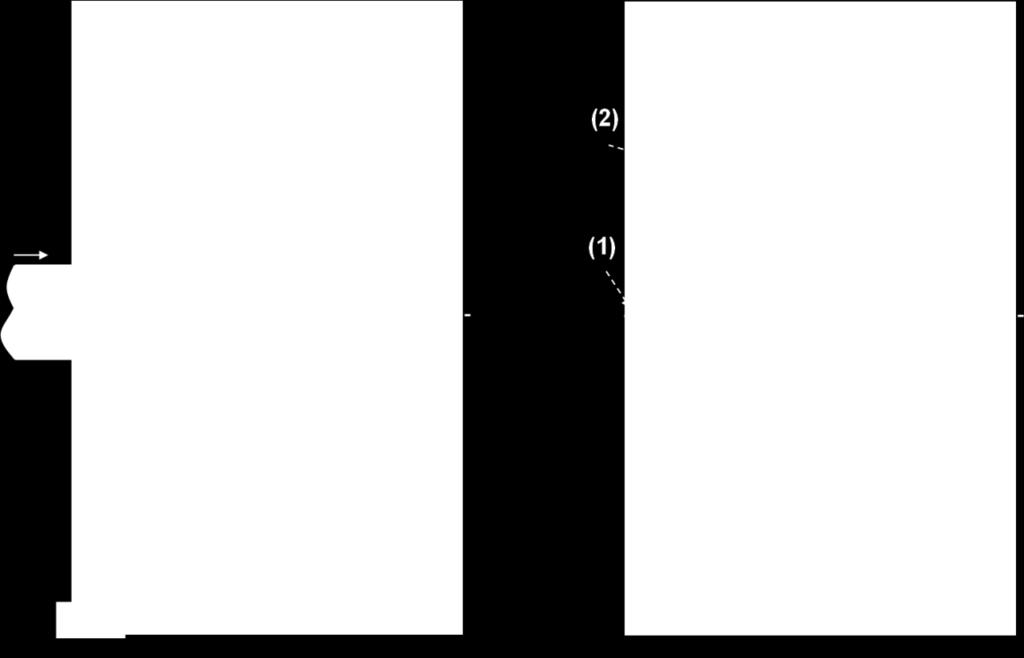
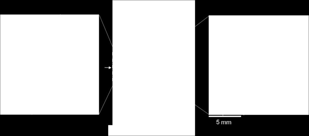
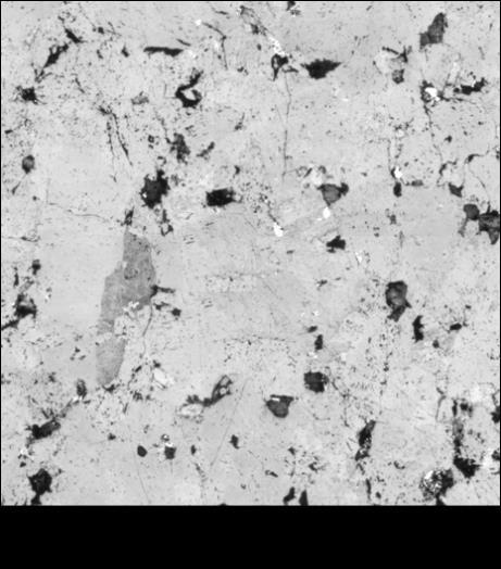
8 In the present experiments, a granite slab of size mm 3 is impacted by an aluminum alloy projectile (21 mm in diameter and 40 mm in length) at a speed of 150 m/s. Two tests are performed with similar results and the crack pattern after impact is indicated in Fig. 3. There are different types of damaged zones in the target with respect to crack density and orientation (see Fig. 3). In the first region (marked (1) in Fig. 3(b)) in front of the projectile there is a small zone consisting of a very large number of cracks in random directions. The material in this region can be considered as crushed due to high compressive stresses beneath the projectile. The second region (marked (2) in Fig. 3(b)) includes a few hoop cracks mostly located close to the confinement. The reason behind the formation of these cracks is not totally clear. However, they presumably form because of wave reflections. The third region (marked (3) in Fig. 3(b)) includes long macroscopic radial cracks, which initiate because of the circumferential motion of the material. The cracks in the second and third region are marked in Fig. 3(b) for the sake of clarity. It is likely that these are mode I cracks initiated by high tensile stresses. In the remaining part of the specimen, outside the above regions, there are an enormous number of cracks, of size up to a few millimeters, in different directions. Most of these cracks are formed along the grain boundaries and some of them are only visible under a microscope. It should be noted that in the region close to the free boundaries, the amount of macroscopic cracks locally increases due to reflections of the compressive wave (spallation). By observing the surface of the specimen under a microscope, a large number of small cracks can be observed (see Fig. 4). The black color in the micrographs indicates the points where the material is missing, i.e. the cracks. A small part of one of the long macrocracks in Fig. 3(b) is visible in Fig. 4(b), the bold curved line crossing the whole image, together with small cracks oriented in different directions. Note that the amount of damage is decreasing with the distance from the impact point. In order to evaluate the crack density from the experiment, a line is traced across the micrographs (Fig. 4) and the average distance between the cracks, d, is obtained by dividing the line length by the number of crossed cracks. The crack density is then roughly evaluated as (1/d) 3, which in this case is about and 10 9 cracks/m 3 in Fig. 4 (b) and (c) respectively. It should be emphasized that these numbers are rough estimates. A representative micrograph of the intact specimen is also shown in Fig. 5. A typical feature of the granite material studied herein is the large number of pre-existing cracks, both at the grain boundaries and also across the grains [3], [4]. When compared to Fig. 4, the amount of damage is noticeably increasing after impact. 4.2 Numerical modeling The equation of motion is discretized using the FE method and the explicit time integration method is employed. The numerical simulation is carried through utilizing in full the KST-DFH material model described above and implemented as a VUMAT subroutine in the Abaqus explicit software [13,28]. The strain increments are given as input whereas final stress tensor and state variables are computed as output variables of the routine. In the subroutine, the integration scheme is mainly composed of two steps. In the first one, a microscopic stress tensor is calculated considering the KST constitutive law alone. The level of pressure is calculated from the volumetric strain increment considering a piece-wise linear relationship between the volumetric strain and the hydrostatic pressure. The microscopic deviatoric stress tensor is 8
9 calculated considering the isotropic pressure dependent yield stress criterion defined in Eq. (1). In the second step, the three eigen values of microscopic stress tensor are computed. In case of positive microscopic eigen stresses, a damage variable is calculated according to Eq.(13) and the macroscopic stress is derived (see Eq.(14). Finally, the macroscopic stress tensor is written in the initial basis. The numerical simulation of the EOI test is performed in 3D. The quarter-symmetry model consists of 8- node linear elements (hexahedra) with reduced integration. The element edge size is 0.5 mm in the rock specimen (see Fig. 6). Surface to surface contact is used in the numerical simulation and all of the KST- DFH model variables are evaluated and extracted during the analysis. The damage variable, D 1, field is shown in Fig. 7. When the damage variable reaches unity, it indicates that the element is totally damaged, the physical interpretation being that single or multiple cracks normal to the maximum principal stress direction are open. Similar to D 1, the second and third damage components grow during the analysis by increasing the load. Near the impact point, the material behaves plastically due to high levels of confining pressure. Thus the hydrostatic compressive stresses in this region prevent the fragmentation process. The radial cracks due to hoop tensile stresses induced by the particle motion in the radial direction are also shown in Fig. 7. The compressive stress wave is reflected from the specimen boundaries as a relaxation wave and creates some cracks close to the rear face. Some cracks are also formed due to Rayleigh wave propagation along the free surface of the impact side. It should be emphasized that in the model, crack initiation and growth is solely due to positive principal tensile stresses including the possible contribution from shear stresses. Fracturing due to high compressive stresses (for example in the compacted zone close to the region of impact) is indicated in the model by high values on the accumulated plastic strain. The crack density, due to the maximum principal stress, predicted by the model is compared to the experimental results. The crack density from the numerical simulation is illustrated in Fig. 8. The results are in logarithmic scale. The crack density in the same region as in Fig. 4 (b) and (c) is about and crack/m 3 respectively which is higher than the experimental results. This difference will be explained in more detail below. The number of radial cracks in the numerical results is very large while there are not that many long radial macrocracks visible in the experimental results. This is most likely due to the presence of large so called structural cracks in the specimen introduced during fabrication of the EOI specimen [20]. This feature can indeed be of significant importance for EOI testing of granite as the fabrication of samples requires substantial processing of the material. To investigate the effect of the structural cracks, the specimen is first impacted at 20 m/s, in a numerical simulation, in order to produce an initial damage. The specimen is subsequently impacted at 150 m/s (similarly as in the experiment). As can be seen in Fig. 9, the damage pattern changes considerably and the number of the radial cracks decreases. The initial cracks prevent some new cracks to form. This effect leads to more realistic results when compared to the experimental observations. The effect of these initial cracks, however, will be further investigated in future studies by introducing these cracks in a more appropriate way. This analysis is only preliminary and leads to a qualitative agreement between experiments and simulations. 9
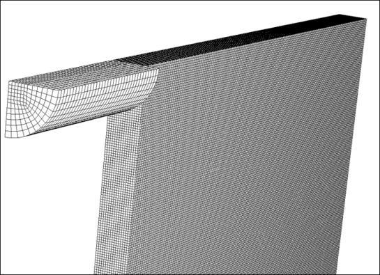
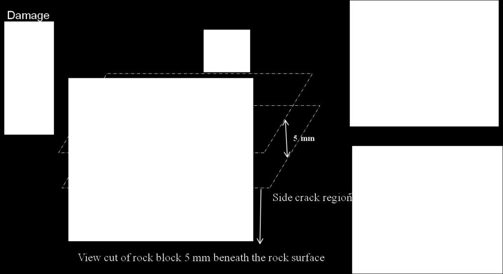
10 Furthermore, the crack density decreases when initial cracking is present and becomes much closer to the experimental results (see Fig. 10). Accordingly, the results shown in Figs. 9 and 10 give some confidence in the present numerical approach and an analysis of percussive drilling is then performed below. A mesh study for the model is reported by Forquin and Hild before [13]. The boundary between single and multiple fragmentations is affected by the FE size. The smaller the element size, the smaller the region for which multiple fragmentation occurs in the numerical results, because for the same stress rate level, it is more likely for a smaller element to reach failure due to a single crack. 5 Modeling of percussive drilling The same numerical tools as above are used to model the percussive drilling problem. Again, the KST- DFH material model is utilized via a VUMAT subroutine in the Abaqus explicit software [13,28]. A typical drill bit has about ten buttons made of hard steel. To simplify the problem, only one hemispherical button from the bit is considered. Initial damage is not considered in detail as most often in a practical situation there is no preparation of the rock before drilling. Consequently, as discussed previously in the context of the EOI test and in detail in Ref. [20], the formation of large structural cracks should be of less importance. Some simulations relevant to repeated impact are performed. The incident stress pulse has a level of 200 MPa with duration of s and with a rising and descending time of 10-5 s. A hemispherical indenter (5 mm in radius) is chosen. The steel drill rod is 1 m in length and 6 mm in radius. In a real tool the drill rod cross sectional area is a bit larger than the sum the cross sectional areas of all buttons. Accordingly, the drill rod radius is taken a bit larger than the button in order to take into account the geometric impedance difference between them. Both the drill rod and the button are assumed to be elastically deformable with elastic moduli equal to 200 GPa and 800 GPa respectively. A block of rock with a size of mm 3 is exposed to impact. The finite element mesh used in the simulation is shown in Fig node linear elements with reduced integration are used in the simulations. Infinite elements are used at the rock boundaries to eliminate the wave reflection. Selected simulation results for the damage variable, induced by the maximum tensile principal stress, are shown in Fig. 12. Firstly, it is compared to cracking under quasi-static conditions. A typical fracture pattern in a rock material due to quasi-static indentation has been determined by Tan et al.[29] It includes different types of cracks and also a high compressive part under the indenter called the crushed zone, see Fig. 13. Although being dynamically loaded, similar types of cracks are captured from the numerical results (Fig. 12). In the region ahead of the indenter, a crushed zone develops. The hydrostatic pressure in this region reaches more than 2 GPa according to the numerical results. It should be emphasized that the high hydrostatic stresses will lead to high values on the effective plastic strain and the damage formed in the crushed zone is a consequence of tensile stresses due to a gradual increase of the contact area. Radial cracks, or radial and median cracks combined, are formed during loading and propagate even more during the unloading phase, see Fig. 12(b). Side cracks, which are mainly formed during the unloading stage and are considered as the most efficient way of removing rock material, are also captured. Fig. 14 shows the damage state in a view cut of the rock block 5 mm beneath the indenter at the end of the loading and unloading stages. The side cracks are marked. These cracks interact with similar types from neighboring buttons and a significant part of the material is removed when they coalesce. In this context, it should also 10 b)
11 be mentioned that all the three damage variables, in the KST-DFH material model, grow during the simulations. The penetration resistance is obtained from the indentation bit force (P b ) versus indentation penetration (h) response. The force-penetration (P b h) curve of the drill bit is shown in Fig. 15. By accounting for the symmetric boundary conditions and the number of buttons per drill bit, the penetration stiffness, K s, value is 340 kn/mm. The values of penetration per impact and also the penetration stiffness K s obtained from the numerical simulations are in good agreement with real drilling results [10]. If the KST model is considered without any damage in the same drilling simulation as above, the penetration rate decreases considerably with a penetration stiffness of about 548 KN/mm, see Fig. 15. This means that in the absence of damage as a dissipation mechanism, the rock behaves as a stronger material and becomes more resistant to the tool indentation. Mesh size effect on the fracture pattern and the penetration stiffness of the above explained percussive drilling problem have been investigated. It is concluded that the very small details of the crack pattern may be considered as mesh dependent in a sense that the cracks are more likely follow the mesh patterns. However, the size of the damaged zone and the general features of the material response are mainly meshindependent. As discussed above, initial damage is not explicitly considered in the present drilling analyses based on the fact that structural cracking is expected to be very limited prior to first impact. It should be emphasized that a controlled introduction of such cracks can be of major importance from a drilling efficiency point of view and, accordingly, this feature will be investigated in detail in future studies. However, as mentioned above, some simulations relevant to repeated impact were performed. In short, it was then found that the cracks formed at first impact continued to grow to a very limited extent while a large zone of crushed material was formed below the indenter leading to a less effective drilling procedure. Based on this result a controlled introduction of structural cracks, in order improve drilling efficiency, becomes an even more desirable feature. 6 Conclusions Percussive drilling in granite has been investigated experimentally and numerically using finite element simulations. The KST-DFH material model was used to describe the material constitutively and the material parameters are calibrated for Bohus granite by a set of previously performed experiments [20]. The numerical simulations were performed using a VUMAT subroutine in the commercial software Abaqus [13,28]. Edge-On Impact (EOI) tests were performed to validate the numerical model. The fracture pattern and the crack density from the numerical analysis were in qualitative agreement with the experimental results. It was found that effects due to large initial (structural) cracks must be carefully accounted for. These cracks can prevent subsequent initiations and considerably decrease the number of large cracks. A 3D numerical simulation was then performed to model the percussive drilling problem. It was shown that the fracture pattern at drilling resembles that found under quasi-static indentation of rock materials. In particular, side cracks, which are the most preferable type for removing material, were mainly formed 11
12 during the unloading stage. The force-penetration curve and the corresponding value on the penetration stiffness, K s, were in a good agreement with real drilling data. The possibility of introducing initial cracks in the material, in order to improve the drilling efficiency, was briefly investigated and discussed. 12
13 7 References [1] Saksala T. Numerical Modelling of Rock Fracture in Percussive Drilling. PhD Thesis, Tampere University of Technology, Finland, [2] Fang Z, Harrison JP. Development of a local degradation approach to the modelling of brittle fracture in heterogeneous rocks. International Journal of Rock Mechanics and Mining Sciences 2002;39: [3] Peng S, Johnson AM. Crack growth and faulting in cylindrical specimens of Chelmsford granite. International Journal of Rock Mechanics and Mining Sciences & Geomechanics Abstracts, vol. 9, Elsevier; 1972, p [4] Bäckström A, Antikainen J, Backers T, Feng X, Jing L, Kobayashi A, et al. Numerical modelling of uniaxial compressive failure of granite with and without saline porewater. International Journal of Rock Mechanics and Mining Sciences 2008;45: [5] Shimada M, Cho A, Yukutake H. Fracture strength of dry silicate rocks at high confining pressures and activity of acoustic emission. Tectonophysics 1983;96: [6] Liu HY, Kou SQ, Lindqvist P-A, Tang CA. Numerical simulation of the rock fragmentation process induced by indenters. International Journal of Rock Mechanics and Mining Sciences 2002;39: [7] Wang SY, Sloan SW, Liu HY, Tang CA. Numerical simulation of the rock fragmentation process induced by two drill bits subjected to static and dynamic (impact) loading. Rock Mechanics and Rock Engineering 2011;44: [8] Saksala T. Damage viscoplastic consistency model with a parabolic cap for rocks with brittle and ductile behavior under low-velocity impact loading. International Journal for Numerical and Analytical Methods in Geomechanics 2010;34: [9] Saksala T. Numerical modelling of bit rock fracture mechanisms in percussive drilling with a continuum approach. International Journal for Numerical and Analytical Methods in Geomechanics 2011;35: [10] Saksala T. 3D numerical modelling of bit rock fracture mechanisms in percussive drilling with a multiple-button bit. International Journal for Numerical and Analytical Methods in Geomechanics 2013;37: [11] Chiang LE, Elias DA. A 3D FEM methodology for simulating the impact in rock-drilling hammers. International Journal of Rock Mechanics and Mining Sciences 2008;45:
14 [12] Thuro K, Schormair N. Fracture propagation in anisotropic rock during drilling and cutting. Geomechanics and Tunnelling 2008;1:8 17. [13] Forquin P, Hild F. A Probabilistic Damage Model of the Dynamic Fragmentation Process in Brittle Materials. Advances in Applied Mechanics 2010;Volume 44:1 72. [14] Krieg RD. A simple constitutive description for soils and crushable foams. Report, SC- DR , Sandia National Laboratory [15] Swenson D V, Taylor LM. A finite element model for the analysis of tailored pulse stimulation of boreholes. International Journal for Numerical and Analytical Methods in Geomechanics 1983;7: [16] Denoual C, Hild F. A damage model for the dynamic fragmentation of brittle solids. Computer Methods in Applied Mechanics and Engineering 2000;183: [17] Grange S, Forquin P, Mencacci S, Hild F. On the dynamic fragmentation of two limestones using edge-on impact tests. International Journal of Impact Engineering 2008;35: [18] Forquin P, Erzar B. Dynamic fragmentation process in concrete under impact and spalling tests. International Journal of Fracture 2010;163: [19] Erzar B, Forquin P. An experimental method to determine the tensile strength of concrete at high rates of strain. Experimental Mechanics 2010;50: [20] Saadati M, Forquin P, Weddfelt K, Larsson PL, Hild F. On the mechanical behavior of granite material with particular emphasis on the influence from pre-existing cracks and defects. Report, Department of Solid Mechanics, Royal Institute of Technology (KTH), Stockholm, Sweden: Submitted for international publication. [21] Forquin P, Hild F. Dynamic Fragmentation of an Ultr_ahigh-Strength Concrete during Edge-On Impact Tests. Journal of Engineering Mechanics 2008;134: [22] Vajdova V, Baud P, Wong T. Compaction, dilatancy, and failure in porous carbonate rocks. Journal of Geophysical Research: Solid Earth ( ) 2004;109. [23] Weibull W. A Statistical Theory of the Strength of Materials. Report 151, Royal Institute of Technology, Stockholm: [24] Weibull W. A statistical distribution function of wide applicability. Journal of Applied Mechanics 1951;18: [25] Davies DGS. The statistical approach to engineering design in ceramics. Proc. Brit. Ceram. Soc, vol. 22, 1973, p
15 [26] Hild F, Billardon R, Marquis D. Hétérogénéité des contraintes et rupture des matériaux fragiles. Comptes Rendus De l Académie Des Sciences Série 2, Mécanique, Physique, Chimie, Sciences De L'univers, Sciences De La Terre 1992;315: [27] Sallier L, Forquin P. Influence of the Confined Behaviour and the Tensile Strength of Concrete Slabs Under Projectile-Impact. Dynamic Behavior of Materials, Volume 1, Springer; 2013, p [28] Abaqus [29] Tan XC, Kou SQ, Lindqvist P-A. Application of the DDM and fracture mechanics model on the simulation of rock breakage by mechanical tools. Engineering Geology 1998;49:
16 Table legends Table 1 Parameters used in the KST-DFH material model. Details regarding the parameters are found in Section 2 above. 16
17 Mechanical parameters E (GPa) ρ (kg/m 3 ) 2630 DFH model parameters Weibull parameters m 23 σ w (MPa) 18.7 Z eff (mm 3 ) 195 Obscuration volume parameter S 3.74 k 0.38 C (m/s) 4400 KST model parameters Parameters for hydrostatic behavior K (GPa) 31.7 ε v (i) 0; P (i) (MPa) 0; 860 Parameters for deviatoric behavior a 0 (MPa 2 ) 23,500 a 1 (MPa) 465 a Cohesive model parameter α D 1.5 (MPa) 11 n d Table 1 17
18 Figure legends Fig. 1. Quasi-oedometric test results together with the KST model (after [20]). Fig. 2. Schematic of the EOI test with the sarcophagus configuration. Fig. 3. Granite specimen after impact by an aluminum projectile (a), damage pattern is marked to be observable (b). Specific regions (1), (2) and (3), are also shown. Fig. 4. Granit specimen after impact by the aluminum projectile (a), micrograph of the specimen at a distance of 25 mm (b), and 50 mm (c) from the impact point. The dashed yellow boxes will be used to compare the model predictions with the experimentally evaluated crack density. Fig. 5. Micrograph of the intact specimen. Fig. 6. FE mesh used in the simulations of the EOI test. Quarter-symmetry model with node linear elements. Fig. 7. FE simulation results of the EOI test. Damage variable D 1 20 μs (a), and 40 μs (b) after impact (velocity: 150 m/s). Fig. 8. FE simulation results of the EOI test. Crack density (1/m 3, logarithmic scale) due to the maximum principal stress 20 μs (a), and 40 μs (b) after impact (velocity 150 m/s). Fig. 9. FE simulation results of the EOI test. Damage variable D 1 at the end of the first impact at 20 m/s (a), and 40 μs (b) after the second impact at 150 m/s. Fig. 10. FE simulation results of the EOI test. Crack density (1/m 3, logarithmic scale) due to the maximum principal stress at end of first impact at 20 m/s (a), and 40 μs (b) after the second impact at 150 m/s. Fig. 11. FE mesh used in the simulations of percussive drilling. Due to symmetries only a quarter of the problem is modeled with node elements. Fig. 12. FE simulation results of percussive drilling. Damage variable D 1 at the end of loading (a) and at the end of unloading (b) phases. Fig. 13 Cracking pattern in rocks at quasi-static indentation [29]. Fig. 14. FE simulation results of percussive drilling. Side crack formation in a view cut 5 mm beneath the indenter at the end of loading (a) at the end of unloading (b). Fig. 15. FE simulation results of percussive drilling. Force-penetration (P b h) curve of the drill bit based on the KST-DFH and KST material models. 18
19 Fig. 1 19
20 Fig. 2 20

21 (a) (b) Fig. 3 21
 Fig.")
22 (b) (a) (c) Fig. 4 22
23 Fig. 5 23
24 Fig. 6 24

25 (a) (b) Fig. 7 25

26 (a) (b) Fig. 8 26

27 (a) (b) Fig. 9 27

28 (a) (b) Fig


29 Fig


30 Fig
31 Indenter Radial crack Crater Side crack Crushed zone Median crack Cracked zone Fig
 Fig.")
32 a) b) (a) (b) Fig
33 Fig
On the inelastic mechanical behavior of granite: Study based on quasi-oedometric and indentation tests
 On the inelastic mechanical behavior of granite: Study based on quasi-oedometric and indentation tests H. Shariati a, M. Saadati a,b,*, A. Bouterf c, K. Weddfelt b, P.-L. Larsson a, F. Hild c a Department
Module 5: Failure Criteria of Rock and Rock masses. Contents Hydrostatic compression Deviatoric compression
 FAILURE CRITERIA OF ROCK AND ROCK MASSES Contents 5.1 Failure in rocks 5.1.1 Hydrostatic compression 5.1.2 Deviatoric compression 5.1.3 Effect of confining pressure 5.2 Failure modes in rocks 5.3 Complete
The Frictional Regime
 The Frictional Regime Processes in Structural Geology & Tectonics Ben van der Pluijm WW Norton+Authors, unless noted otherwise 1/25/2016 10:08 AM We Discuss The Frictional Regime Processes of Brittle Deformation
Discrete Element Modelling of a Reinforced Concrete Structure
 Discrete Element Modelling of a Reinforced Concrete Structure S. Hentz, L. Daudeville, F.-V. Donzé Laboratoire Sols, Solides, Structures, Domaine Universitaire, BP 38041 Grenoble Cedex 9 France sebastian.hentz@inpg.fr
Classical fracture and failure hypotheses
 : Chapter 2 Classical fracture and failure hypotheses In this chapter, a brief outline on classical fracture and failure hypotheses for materials under static loading will be given. The word classical
Numerical investigation of EDZ development around a deep polymetallic ore mine
 Paper No. 198 ISMS 2016 Numerical investigation of EDZ development around a deep polymetallic ore mine Mountaka Souley a *, Marwan Al Heib a, Vincent Renaud a a INERIS, c/o Ecole des Mines de Nancy, Campus
Chapter 7. Highlights:
 Chapter 7 Highlights: 1. Understand the basic concepts of engineering stress and strain, yield strength, tensile strength, Young's(elastic) modulus, ductility, toughness, resilience, true stress and true
Lecture #7: Basic Notions of Fracture Mechanics Ductile Fracture
 Lecture #7: Basic Notions of Fracture Mechanics Ductile Fracture by Dirk Mohr ETH Zurich, Department of Mechanical and Process Engineering, Chair of Computational Modeling of Materials in Manufacturing
Brittle Deformation. Earth Structure (2 nd Edition), 2004 W.W. Norton & Co, New York Slide show by Ben van der Pluijm
, 2004 W.W. Norton & Co, New York Slide show by Ben van der Pluijm") Lecture 6 Brittle Deformation Earth Structure (2 nd Edition), 2004 W.W. Norton & Co, New York Slide show by Ben van der Pluijm WW Norton, unless noted otherwise Brittle deformation EarthStructure (2 nd
Lecture 6 Brittle Deformation Earth Structure (2 nd Edition), 2004 W.W. Norton & Co, New York Slide show by Ben van der Pluijm WW Norton, unless noted otherwise Brittle deformation EarthStructure (2 nd
Shock enhancement of cellular structures under impact loading: Part II Analysis
 Shock enhancement of cellular structures under impact loading: Part II Analysis S. Pattofatto, 1 I. Elnasri, 1 H. Zhao, 1* H. Tsitsiris 1 F. Hild 1 and Y. Girard 2 1 Laboratoire de Mécanique et Technologie
Numerical modeling of standard rock mechanics laboratory tests using a finite/discrete element approach
 Numerical modeling of standard rock mechanics laboratory tests using a finite/discrete element approach S. Stefanizzi GEODATA SpA, Turin, Italy G. Barla Department of Structural and Geotechnical Engineering,
Wellbore stability analysis in porous carbonate rocks using cap models
 Wellbore stability analysis in porous carbonate rocks using cap models L. C. Coelho 1, A. C. Soares 2, N. F. F. Ebecken 1, J. L. D. Alves 1 & L. Landau 1 1 COPPE/Federal University of Rio de Janeiro, Brazil
1. Background. is usually significantly lower than it is in uniaxial tension
 NOTES ON QUANTIFYING MODES OF A SECOND- ORDER TENSOR. The mechanical behavior of rocks and rock-like materials (concrete, ceramics, etc.) strongly depends on the loading mode, defined by the values and
Rock Mechanics Laboratory Tests for Petroleum Applications. Rob Marsden Reservoir Geomechanics Advisor Gatwick
 Rock Mechanics Laboratory Tests for Petroleum Applications Rob Marsden Reservoir Geomechanics Advisor Gatwick Summary A wide range of well established and proven laboratory tests are available for petroleum
Table of Contents. Foreword... xiii Introduction... xv
 Foreword.... xiii Introduction.... xv Chapter 1. Controllability of Geotechnical Tests and their Relationship to the Instability of Soils... 1 Roberto NOVA 1.1. Introduction... 1 1.2. Load control... 2
University of Sheffield The development of finite elements for 3D structural analysis in fire
 The development of finite elements for 3D structural analysis in fire Chaoming Yu, I. W. Burgess, Z. Huang, R. J. Plank Department of Civil and Structural Engineering StiFF 05/09/2006 3D composite structures
Engineering Solid Mechanics
 }} Engineering Solid Mechanics 1 (2013) 1-8 Contents lists available at GrowingScience Engineering Solid Mechanics homepage: www.growingscience.com/esm Impact damage simulation in elastic and viscoelastic
Laboratory 4 Bending Test of Materials
 Department of Materials and Metallurgical Engineering Bangladesh University of Engineering Technology, Dhaka MME 222 Materials Testing Sessional.50 Credits Laboratory 4 Bending Test of Materials. Objective
Understanding hydraulic fracture variability through a penny shaped crack model for pre-rupture faults
 Penny shaped crack model for pre-rupture faults Understanding hydraulic fracture variability through a penny shaped crack model for pre-rupture faults David Cho, Gary F. Margrave, Shawn Maxwell and Mark
Effect of buttress on reduction of rock slope sliding along geological boundary
 Paper No. 20 ISMS 2016 Effect of buttress on reduction of rock slope sliding along geological boundary Ryota MORIYA *, Daisuke FUKUDA, Jun-ichi KODAMA, Yoshiaki FUJII Faculty of Engineering, Hokkaido University,
STRESS DROP AS A RESULT OF SPLITTING, BRITTLE AND TRANSITIONAL FAULTING OF ROCK SAMPLES IN UNIAXIAL AND TRIAXIAL COMPRESSION TESTS
 Studia Geotechnica et Mechanica, Vol. 37, No. 1, 2015 DOI: 10.1515/sgem-2015-0003 STRESS DROP AS A RESULT OF SPLITTING, BRITTLE AND TRANSITIONAL FAULTING OF ROCK SAMPLES IN UNIAXIAL AND TRIAXIAL COMPRESSION
Mechanics of Earthquakes and Faulting
 Mechanics of Earthquakes and Faulting www.geosc.psu.edu/courses/geosc508 Surface and body forces Tensors, Mohr circles. Theoretical strength of materials Defects Stress concentrations Griffith failure
SIMPLIFIED CONCRETE MODELING WITH *MAT_CONCRET_DAMAGE_REL3
 SIMPLIFIED CONCRETE MODELING WITH *MAT_CONCRET_DAMAGE_REL3 Leonard E Schwer Schwer Engineering & Consulting Services, Windsor CA, USA and L. Javier Malvar Karagozian & Case Structural Engineers, Burbank
Using the Abaqus CDP Model in Impact Simulations
 SAFIR project (http://safir2018.vtt.fi/) The Finnish Research Programme on Nuclear Power Plant Safety 2015-2018 Using the Abaqus CDP Model in Impact Simulations Alexis Fedoroff Technical reseach centre
Hybrid Finite-Discrete Element Modelling of Dynamic Fracture of Rock and Resultant Fragment Arching by Rock Blast
 Hybrid Finite-Discrete Element Modelling of Dynamic Fracture of Rock and Resultant Fragment Arching by Rock Blast H.M. An a, b and H.Y. Liu a * a School of Engineering and ICT, the University of Tasmania,
Module-4. Mechanical Properties of Metals
 Module-4 Mechanical Properties of Metals Contents ) Elastic deformation and Plastic deformation ) Interpretation of tensile stress-strain curves 3) Yielding under multi-axial stress, Yield criteria, Macroscopic
5 ADVANCED FRACTURE MODELS
 Essentially, all models are wrong, but some are useful George E.P. Box, (Box and Draper, 1987) 5 ADVANCED FRACTURE MODELS In the previous chapter it was shown that the MOR parameter cannot be relied upon
3D MATERIAL MODEL FOR EPS RESPONSE SIMULATION
 3D MATERIAL MODEL FOR EPS RESPONSE SIMULATION A.E. Swart 1, W.T. van Bijsterveld 2, M. Duškov 3 and A. Scarpas 4 ABSTRACT In a country like the Netherlands, construction on weak and quite often wet soils
Application of Three Dimensional Failure Criteria on High-Porosity Chalk
 , 5-6 May 00, Trondheim, Norway Nordic Energy Research Programme Norwegian U. of Science and Technology Application of Three Dimensional Failure Criteria on High-Porosity Chalk Roar Egil Flatebø and Rasmus
Simulation of the cutting action of a single PDC cutter using DEM
 Petroleum and Mineral Resources 143 Simulation of the cutting action of a single PDC cutter using DEM B. Joodi, M. Sarmadivaleh, V. Rasouli & A. Nabipour Department of Petroleum Engineering, Curtin University,
Cracking in Quasi-Brittle Materials Using Isotropic Damage Mechanics
 Cracking in Quasi-Brittle Materials Using Isotropic Damage Mechanics Tobias Gasch, PhD Student Co-author: Prof. Anders Ansell Comsol Conference 2016 Munich 2016-10-12 Contents Introduction Isotropic damage
Experiments and Numerical Simulations on Stress-State-Dependence of Ductile Damage Criteria
 Experiments and Numerical Simulations on Stress-State-Dependence of Ductile Damage Criteria Michael Brünig, Steffen Gerke and Daniel Brenner Abstract The paper deals with a series of new experiments and
Abstract. 1 Introduction
 Contact analysis for the modelling of anchors in concrete structures H. Walter*, L. Baillet** & M. Brunet* *Laboratoire de Mecanique des Solides **Laboratoire de Mecanique des Contacts-CNRS UMR 5514 Institut
The design of a formula student front impact attenuator
 The design of a formula student front impact attenuator J.M.J. Schormans MT 10.06 Supervisors: dr. ir. Varvara Kouznetsova Eindhoven University of Technology Department of Mechanical Engineering Computational
MASONRY MICRO-MODELLING ADOPTING A DISCONTINUOUS FRAMEWORK
 MASONRY MICRO-MODELLING ADOPTING A DISCONTINUOUS FRAMEWORK J. Pina-Henriques and Paulo B. Lourenço School of Engineering, University of Minho, Guimarães, Portugal Abstract Several continuous and discontinuous
Fluid driven cohesive crack propagation in quasi-brittle materials
 Fluid driven cohesive crack propagation in quasi-brittle materials F. Barpi 1, S. Valente 2 Department of Structural and Geotechnical Engineering, Politecnico di Torino, Corso Duca degli Abruzzi 24, 10129
MEMORANDUM SUBJECT: CERTIFICATE IN ROCK MECHANICS PAPER 1 : THEORY SUBJECT CODE: COMRMC MODERATOR: H YILMAZ EXAMINATION DATE: OCTOBER 2017 TIME:
 MEMORANDUM SUBJECT: CERTIFICATE IN ROCK MECHANICS PAPER 1 : THEORY EXAMINER: WM BESTER SUBJECT CODE: COMRMC EXAMINATION DATE: OCTOBER 2017 TIME: MODERATOR: H YILMAZ TOTAL MARKS: [100] PASS MARK: (60%)
Lecture #2: Split Hopkinson Bar Systems
 Lecture #2: Split Hopkinson Bar Systems by Dirk Mohr ETH Zurich, Department of Mechanical and Process Engineering, Chair of Computational Modeling of Materials in Manufacturing 2015 1 1 1 Uniaxial Compression
The plastic behaviour of silicon subjected to micro-indentation
 JOURNAL OF MATERIALS SCIENCE 31 (1996) 5671-5676 The plastic behaviour of silicon subjected to micro-indentation L. ZHANG, M. MAHDI Centre for Advanced Materials Technology, Department of Mechanical and
NORMAL STRESS. The simplest form of stress is normal stress/direct stress, which is the stress perpendicular to the surface on which it acts.
 NORMAL STRESS The simplest form of stress is normal stress/direct stress, which is the stress perpendicular to the surface on which it acts. σ = force/area = P/A where σ = the normal stress P = the centric
Calibration and Experimental Validation of LS-DYNA Composite Material Models by Multi Objective Optimization Techniques
 9 th International LS-DYNA Users Conference Optimization Calibration and Experimental Validation of LS-DYNA Composite Material Models by Multi Objective Optimization Techniques Stefano Magistrali*, Marco
Mechanics of Earthquakes and Faulting
 Mechanics of Earthquakes and Faulting Lectures & 3, 9/31 Aug 017 www.geosc.psu.edu/courses/geosc508 Discussion of Handin, JGR, 1969 and Chapter 1 Scholz, 00. Stress analysis and Mohr Circles Coulomb Failure
Proceedings of the ASME th International Conference on Ocean, Offshore and Arctic Engineering OMAE2016 June 19-24, 2016, Busan, South Korea
 Proceedings of the ASME 26 35th International Conference on Ocean, Offshore and Arctic Engineering OMAE26 June 9-24, 26, Busan, South Korea OMAE26-54554 LOCAL STRAIN AND STRESS CALCULATION METHODS OF IRREGULAR
A Finite Element Study of Elastic-Plastic Hemispherical Contact Behavior against a Rigid Flat under Varying Modulus of Elasticity and Sphere Radius
 Engineering, 2010, 2, 205-211 doi:10.4236/eng.2010.24030 Published Online April 2010 (http://www. SciRP.org/journal/eng) 205 A Finite Element Study of Elastic-Plastic Hemispherical Contact Behavior against
Rock Material. Chapter 3 ROCK MATERIAL HOMOGENEITY AND INHOMOGENEITY CLASSIFICATION OF ROCK MATERIAL
 Chapter 3 Rock Material In all things of nature there is something of the marvelous. Aristotle ROCK MATERIAL The term rock material refers to the intact rock within the framework of discontinuities. In
3D Finite Element analysis of stud anchors with large head and embedment depth
 3D Finite Element analysis of stud anchors with large head and embedment depth G. Periškić, J. Ožbolt & R. Eligehausen Institute for Construction Materials, University of Stuttgart, Stuttgart, Germany
Computers and Geotechnics
 Computers and Geotechnics 39 (212) 16 Contents lists available at SciVerse ScienceDirect Computers and Geotechnics journal homepage: www.elsevier.com/locate/compgeo Numerical analysis of the failure process
The Influence of Contact Friction on the Breakage Behavior of Brittle Granular Materials using DEM
 The Influence of Contact Friction on the Breakage Behavior of Brittle Granular Materials using DEM *Yi-Ming Liu 1) and Hua-Bei Liu 2) 1), 2) School of Civil Engineering and Mechanics, Huazhong University
THE BEHAVIOUR OF REINFORCED CONCRETE AS DEPICTED IN FINITE ELEMENT ANALYSIS.
 THE BEHAVIOUR OF REINFORCED CONCRETE AS DEPICTED IN FINITE ELEMENT ANALYSIS. THE CASE OF A TERRACE UNIT. John N Karadelis 1. INTRODUCTION. Aim to replicate the behaviour of reinforced concrete in a multi-scale
Exercise: concepts from chapter 8
 Reading: Fundamentals of Structural Geology, Ch 8 1) The following exercises explore elementary concepts associated with a linear elastic material that is isotropic and homogeneous with respect to elastic
Geology 229 Engineering Geology. Lecture 5. Engineering Properties of Rocks (West, Ch. 6)
") Geology 229 Engineering Geology Lecture 5 Engineering Properties of Rocks (West, Ch. 6) Common mechanic properties: Density; Elastic properties: - elastic modulii Outline of this Lecture 1. Uniaxial rock
Geology 229 Engineering Geology Lecture 5 Engineering Properties of Rocks (West, Ch. 6) Common mechanic properties: Density; Elastic properties: - elastic modulii Outline of this Lecture 1. Uniaxial rock
INFLUENCE OF A WELDED PIPE WHIP RESTRAINT ON THE CRITICAL CRACK SIZE IN A 90 BEND
 18th International Conference on Structural Mechanics in Reactor Technology (SMiRT 18) Beijing, China, August 7-12, 25 SMiRT18-G8-5 INFLUENCE OF A WELDED PIPE WHIP RESTRAINT ON THE CRITICAL CRACK SIZE
Failure modes of glass panels subjected to soft missile impact
 Failure modes of glass panels subjected to soft missile impact L. R. Dharani & J. Yu Dept. of Mech. and Aerospace Engineering and Engineering Mechanics, University of Missouri-Rolla, U.S.A. Abstract Damage
Tensile stress strain curves for different materials. Shows in figure below
 Tensile stress strain curves for different materials. Shows in figure below Furthermore, the modulus of elasticity of several materials effected by increasing temperature, as is shown in Figure Asst. Lecturer
3D simulations of an injection test done into an unsaturated porous and fractured limestone
 3D simulations of an injection test done into an unsaturated porous and fractured limestone A. Thoraval *, Y. Guglielmi, F. Cappa INERIS, Ecole des Mines de Nancy, FRANCE *Corresponding author: Ecole des
Pillar strength estimates for foliated and inclined pillars in schistose material
 Pillar strength estimates for foliated and inclined pillars in schistose material L.J. Lorig Itasca Consulting Group, Inc., Minneapolis, MN, USA A. Cabrera Itasca S.A., Santiago, Chile ABSTRACT: Pillar
BRIDGING LAW SHAPE FOR LONG FIBRE COMPOSITES AND ITS FINITE ELEMENT CONSTRUCTION
 Proceedings of ALGORITMY 2012 pp. 353 361 BRIDGING LAW SHAPE FOR LONG FIBRE COMPOSITES AND ITS FINITE ELEMENT CONSTRUCTION VLADISLAV KOZÁK AND ZDENEK CHLUP Abstract. Ceramic matrix composites reinforced
Supplementary Figures
 Fracture Strength (GPa) Supplementary Figures a b 10 R=0.88 mm 1 0.1 Gordon et al Zhu et al Tang et al im et al 5 7 6 4 This work 5 50 500 Si Nanowire Diameter (nm) Supplementary Figure 1: (a) TEM image
Three-Dimensional simulation for the rock fragmentation induced by TBM with GFEM
 Recent Advances in Rock Engineering (RARE 2016) Three-Dimensional simulation for the rock fragmentation induced by TBM with GFEM XY Xu, XH Tang and QS Liu School of Civil Engineering, Wuhan University,
DYNAMIC ANALYSIS OF PILES IN SAND BASED ON SOIL-PILE INTERACTION
 October 1-17,, Beijing, China DYNAMIC ANALYSIS OF PILES IN SAND BASED ON SOIL-PILE INTERACTION Mohammad M. Ahmadi 1 and Mahdi Ehsani 1 Assistant Professor, Dept. of Civil Engineering, Geotechnical Group,
A FINITE ELEMENT STUDY OF ELASTIC-PLASTIC HEMISPHERICAL CONTACT BEHAVIOR AGAINST A RIGID FLAT UNDER VARYING MODULUS OF ELASTICITY AND SPHERE RADIUS
 Proceedings of the International Conference on Mechanical Engineering 2009 (ICME2009) 26-28 December 2009, Dhaka, Bangladesh ICME09- A FINITE ELEMENT STUDY OF ELASTIC-PLASTIC HEMISPHERICAL CONTACT BEHAVIOR
Plane Strain Test for Metal Sheet Characterization
 Plane Strain Test for Metal Sheet Characterization Paulo Flores 1, Felix Bonnet 2 and Anne-Marie Habraken 3 1 DIM, University of Concepción, Edmundo Larenas 270, Concepción, Chile 2 ENS - Cachan, Avenue
20. Rheology & Linear Elasticity
 I Main Topics A Rheology: Macroscopic deformation behavior B Linear elasticity for homogeneous isotropic materials 10/29/18 GG303 1 Viscous (fluid) Behavior http://manoa.hawaii.edu/graduate/content/slide-lava
Effect of intermediate principal stresses on compressive strength of Phra Wihan sandstone
 Rock Mechanics, Fuenkajorn & Phien-wej (eds) 211. ISBN 978 974 533 636 Effect of intermediate principal stresses on compressive strength of Phra Wihan sandstone T. Pobwandee & K. Fuenkajorn Geomechanics
6. NON-LINEAR PSEUDO-STATIC ANALYSIS OF ADOBE WALLS
 6. NON-LINEAR PSEUDO-STATIC ANALYSIS OF ADOBE WALLS Blondet et al. [25] carried out a cyclic test on an adobe wall to reproduce its seismic response and damage pattern under in-plane loads. The displacement
A Critical Plane-energy Model for Multiaxial Fatigue Life Prediction. of Homogeneous and Heterogeneous Materials. Haoyang Wei
 A Critical Plane-energy Model for Multiaxial Fatigue Life Prediction of Homogeneous and Heterogeneous Materials by Haoyang Wei A Thesis Presented in Partial Fulfillment of the Requirements for the Degree
Transactions on Modelling and Simulation vol 10, 1995 WIT Press, ISSN X
 Parameters controlling the numerical simulation validity of damageable composite toughness testing S. Yotte, C. Currit, E. Lacoste, J.M. Quenisset Laboratoire de Genie Meanique - IUT 'A\ Domaine Universitaire,
Fatigue Damage Development in a Steel Based MMC
 Fatigue Damage Development in a Steel Based MMC V. Tvergaard 1,T.O/ rts Pedersen 1 Abstract: The development of fatigue damage in a toolsteel metal matrix discontinuously reinforced with TiC particulates
Finite Element Solution of Nonlinear Transient Rock Damage with Application in Geomechanics of Oil and Gas Reservoirs
 Finite Element Solution of Nonlinear Transient Rock Damage with Application in Geomechanics of Oil and Gas Reservoirs S. Enayatpour*1, T. Patzek2 1,2 The University of Texas at Austin *Corresponding author:
ALGORITHM FOR NON-PROPORTIONAL LOADING IN SEQUENTIALLY LINEAR ANALYSIS
 9th International Conference on Fracture Mechanics of Concrete and Concrete Structures FraMCoS-9 Chenjie Yu, P.C.J. Hoogenboom and J.G. Rots DOI 10.21012/FC9.288 ALGORITHM FOR NON-PROPORTIONAL LOADING
Lecture #6: 3D Rate-independent Plasticity (cont.) Pressure-dependent plasticity
 Pressure-dependent plasticity") Lecture #6: 3D Rate-independent Plasticity (cont.) Pressure-dependent plasticity by Borja Erice and Dirk Mohr ETH Zurich, Department of Mechanical and Process Engineering, Chair of Computational Modeling
Lecture #6: 3D Rate-independent Plasticity (cont.) Pressure-dependent plasticity by Borja Erice and Dirk Mohr ETH Zurich, Department of Mechanical and Process Engineering, Chair of Computational Modeling
MECE 3321 MECHANICS OF SOLIDS CHAPTER 3
 MECE 3321 MECHANICS OF SOLIDS CHAPTER 3 Samantha Ramirez TENSION AND COMPRESSION TESTS Tension and compression tests are used primarily to determine the relationship between σ avg and ε avg in any material.
Shock wave speed and stress-strain relation of aluminium honeycombs under dynamic compression
 EPJ Web of Conferences 83, 7 (8) DYMAT 8 https://doi.org/.5/epjconf/8837 Shock wave speed and stress-strain relation of aluminium honeycombs under dynamic compression Peng Wang,*, Jun Zhang, Haiying Huang,
Multiscale modeling of failure in ABS materials
 Institute of Mechanics Multiscale modeling of failure in ABS materials Martin Helbig, Thomas Seelig 15. International Conference on Deformation, Yield and Fracture of Polymers Kerkrade, April 2012 Institute
Structural behaviour of traditional mortise-and-tenon timber joints
 Structural behaviour of traditional mortise-and-tenon timber joints Artur O. Feio 1, Paulo B. Lourenço 2 and José S. Machado 3 1 CCR Construtora S.A., Portugal University Lusíada, Portugal 2 University
Introduction to Engineering Materials ENGR2000. Dr. Coates
 Introduction to Engineering Materials ENGR2 Chapter 6: Mechanical Properties of Metals Dr. Coates 6.2 Concepts of Stress and Strain tension compression shear torsion Tension Tests The specimen is deformed
Prediction of Elastic Constants on 3D Four-directional Braided
 Prediction of Elastic Constants on 3D Four-directional Braided Composites Prediction of Elastic Constants on 3D Four-directional Braided Composites Liang Dao Zhou 1,2,* and Zhuo Zhuang 1 1 School of Aerospace,
Cracking in Quasi-Brittle Materials Using Isotropic Damage Mechanics
 Cracking in Quasi-Brittle Materials Using Isotropic Damage Mechanics Tobias Gasch *1 and Anders Ansell 1 1 KTH Royal Institute of Technology, Department of Civil and Architectural Engineering *Corresponding
Plasticity R. Chandramouli Associate Dean-Research SASTRA University, Thanjavur
 Plasticity R. Chandramouli Associate Dean-Research SASTRA University, Thanjavur-613 401 Joint Initiative of IITs and IISc Funded by MHRD Page 1 of 9 Table of Contents 1. Plasticity:... 3 1.1 Plastic Deformation,
ISMS Paper No Influence of weak planes on rockburst occurrence. Amin Manouchehrian, Ming Cai *
 Paper No. 176 ISMS 2016 Influence of weak planes on rockburst occurrence Amin Manouchehrian, Ming Cai * Bharti School of Engineering, Laurentian University, Sudbury, Canada, P3E 2C6 MIRARCO, Laurentian
Modelling dynamic fracture propagation in rock
 University of Wollongong Research Online Faculty of Engineering and Information Sciences - Papers: Part B Faculty of Engineering and Information Sciences 2017 Modelling dynamic fracture propagation in
Fig. 1. Different locus of failure and crack trajectories observed in mode I testing of adhesively bonded double cantilever beam (DCB) specimens.
 specimens.") a). Cohesive Failure b). Interfacial Failure c). Oscillatory Failure d). Alternating Failure Fig. 1. Different locus of failure and crack trajectories observed in mode I testing of adhesively bonded double
a). Cohesive Failure b). Interfacial Failure c). Oscillatory Failure d). Alternating Failure Fig. 1. Different locus of failure and crack trajectories observed in mode I testing of adhesively bonded double
Simulation of the mechanical behavior and damage in components made of strain softening cellulose fiber reinforced gypsum materials
 Computational Materials Science 9 (7) 65 74 www.elsevier.com/locate/commatsci Simulation of the mechanical behavior and damage in components made of strain softening cellulose fiber reinforced gypsum materials
STANDARD SAMPLE. Reduced section " Diameter. Diameter. 2" Gauge length. Radius
 MATERIAL PROPERTIES TENSILE MEASUREMENT F l l 0 A 0 F STANDARD SAMPLE Reduced section 2 " 1 4 0.505" Diameter 3 4 " Diameter 2" Gauge length 3 8 " Radius TYPICAL APPARATUS Load cell Extensometer Specimen
Behaviour of Blast-Induced Damaged Zone Around Underground Excavations in Hard Rock Mass Problem statement Objectives
 Behaviour of Blast-Induced Damaged Zone Around Underground Excavations in Hard Rock Mass Problem statement Blast-induced damaged zone can affect the affect stability and performance of tunnel. But, we
A Constitutive Framework for the Numerical Analysis of Organic Soils and Directionally Dependent Materials
 Dublin, October 2010 A Constitutive Framework for the Numerical Analysis of Organic Soils and Directionally Dependent Materials FracMan Technology Group Dr Mark Cottrell Presentation Outline Some Physical
Size Effects In the Crushing of Honeycomb Structures
 45th AIAA/ASME/ASCE/AHS/ASC Structures, Structural Dynamics & Materials Conference 19-22 April 2004, Palm Springs, California AIAA 2004-1640 Size Effects In the Crushing of Honeycomb Structures Erik C.
Damage modeling for Taylor impact simulations
 J. Phys. IV France 134 (2006) 331 337 C EDP Sciences, Les Ulis DOI: 10.1051/jp4:2006134051 Damage modeling for Taylor impact simulations C.E. Anderson Jr. 1, I.S. Chocron 1 and A.E. Nicholls 1 1 Engineering
Lecture #8: Ductile Fracture (Theory & Experiments)
") Lecture #8: Ductile Fracture (Theory & Experiments) by Dirk Mohr ETH Zurich, Department of Mechanical and Process Engineering, Chair of Computational Modeling of Materials in Manufacturing 2015 1 1 1 Ductile
Lecture #8: Ductile Fracture (Theory & Experiments) by Dirk Mohr ETH Zurich, Department of Mechanical and Process Engineering, Chair of Computational Modeling of Materials in Manufacturing 2015 1 1 1 Ductile
A novel approach to predict the growth rate of short cracks under multiaxial loadings
 A novel approach to predict the growth rate of short cracks under multiaxial loadings F. Brugier 1&2, S. Pommier 1, R. de Moura Pinho 2, C. Mary 2 and D. Soria 2 1 LMT-Cachan, ENS Cachan / CNRS / UPMC
EOSC433: Geotechnical Engineering Practice & Design
 EOSC433: Geotechnical Engineering Practice & Design Lecture 1: Introduction 1 of 31 Dr. Erik Eberhardt EOSC 433 (Term 2, 2005/06) Overview This course will examine different principles, approaches, and
MATERIAL MECHANICS, SE2126 COMPUTER LAB 2 PLASTICITY
 MATERIAL MECHANICS, SE2126 COMPUTER LAB 2 PLASTICITY PART A INTEGRATED CIRCUIT An integrated circuit can be thought of as a very complex maze of electronic components and metallic connectors. These connectors
Experimental study of mechanical and thermal damage in crystalline hard rock
 Experimental study of mechanical and thermal damage in crystalline hard rock Mohammad Keshavarz Réunion Technique du CFMR - Thèses en Mécanique des Roches December, 3 nd 2009 1 Overview Introduction Characterization
Multiscale analyses of the behaviour and damage of composite materials
 Multiscale analyses of the behaviour and damage of composite materials Presented by Didier BAPTISTE ENSAM, LIM, UMR CNRS 8006 151 boulevard de l hôpital l 75013 PARIS, France Research works from: K.Derrien,
Effect of embedment depth and stress anisotropy on expansion and contraction of cylindrical cavities
 Effect of embedment depth and stress anisotropy on expansion and contraction of cylindrical cavities Hany El Naggar, Ph.D., P. Eng. and M. Hesham El Naggar, Ph.D., P. Eng. Department of Civil Engineering
ME 2570 MECHANICS OF MATERIALS
 ME 2570 MECHANICS OF MATERIALS Chapter III. Mechanical Properties of Materials 1 Tension and Compression Test The strength of a material depends on its ability to sustain a load without undue deformation
An Evaluation of Simplified Methods to Compute the Mechanical Steady State
 An Evaluation of Simplified Methods to Compute the Mechanical Steady State T. Herbland a,b, G. Cailletaud a, S. Quilici a, H. Jaffal b, M. Afzali b a Mines Paris Paris Tech, CNRS UMR 7633, BP 87, 91003
MMJ1133 FATIGUE AND FRACTURE MECHANICS A - INTRODUCTION INTRODUCTION
 A - INTRODUCTION INTRODUCTION M.N.Tamin, CSMLab, UTM Course Content: A - INTRODUCTION Mechanical failure modes; Review of load and stress analysis equilibrium equations, complex stresses, stress transformation,
This is the accepted version of a paper presented at 2014 IEEE Electrical Insulation Conference (EIC).
.") http://www.diva-portal.org Postprint This is the accepted version of a paper presented at 2014 IEEE Electrical Insulation Conference (EIC). Citation for the original published paper: Girlanda, O., Tjahjanto,
http://www.diva-portal.org Postprint This is the accepted version of a paper presented at 2014 IEEE Electrical Insulation Conference (EIC). Citation for the original published paper: Girlanda, O., Tjahjanto,
APPLICATION OF DAMAGE MODEL FOR NUMERICAL DETERMINATION OF CARRYING CAPACITY OF LARGE ROLLING BEARINGS
 INTERNATIONAL ESIGN CONFERENCE - ESIGN ubrovnik, May 14-17,. APPLICATION OF AMAGE MOEL FOR NUMERICAL ETERMINATION OF CARRYING CAPACITY OF LARGE ROLLING BEARINGS Robert Kunc, Ivan Prebil, Tomaž Rodic and