The toughness of epoxy polymers and fibre composites modified with rubber microparticles and silica nanoparticles
|
|
|
- Paul Jenkins
- 6 years ago
- Views:
Transcription
1 Accepted for publication in Journal of Materials Science The toughness of epoxy polymers and fibre composites modified with rubber microparticles and silica nanoparticles T.H. Hsieh, A.J. Kinloch *, K. Masania, J. Sohn Lee, A.C. Taylor * Department of Mechanical Engineering, Imperial College London, South Kensington Campus, London SW7 2AZ, UK. S. Sprenger Nanoresins AG, Charlottenburger Strasse 9, Geesthacht, Germany. Abstract The present paper investigates the effect of adding silica nanoparticles to an anhydride-cured epoxy polymer in bulk and when used as the matrix of carbon- and glass-fibre reinforced composites. The formation of hybrid epoxy polymers, containing both silica nanoparticles and carboxyl-terminated butadiene-acrylonitrile (CTBN) rubber microparticles, is also discussed. The structure/property relationships are considered, with an emphasis on the toughness and the toughening mechanisms. The fracture energy of the bulk epoxy polymer was increased from 77 to 212 J/m 2 by the presence of 20 wt.% of silica nanoparticles. The observed toughening mechanisms that were operative were (a) plastic shear-yield bands, and (b) debonding of the matrix from the silica nanoparticles, followed by plastic void-growth of the epoxy. The largest increases in toughness observed were for the hybrid materials. Here a maximum fracture energy of 965 J/m 2 was measured for a hybrid epoxy polymer containing 9 wt.% and 15 wt.% of the rubber microparticles and silica nanoparticles, respectively. Most noteworthy was the observation that these increases in the toughness of the bulk polymers were found to be transferred to the fibre composites. Indeed, the interlaminar fracture energies for the fibre-composites materials were increased even further by a fibre-bridging toughening mechanism. The present work also extends an existing model to predict the toughening effect of the nanoparticles in a thermoset polymer. There was excellent agreement between the predictions and the experimental data for the epoxy containing the silica nanoparticles, and for epoxy polymers containing micrometre-sized glass particles. The latter, relatively large, glass particles were investigated to establish whether a nanoeffect, with respect to increasing the toughness of the epoxy bulk polymers, did indeed exist. Keywords: Epoxy polymers; Fibre composites; Fracture energy; Nanoparticles; Toughening mechanisms. * Corresponding authors: A.C. Taylor: Tel: , Fax: , a.c.taylor@imperial.ac.uk A.J. Kinloch: Tel: , Fax: , a.kinloch@imperial.ac.uk
2 1. Introduction Adhesives and fibre-composite materials are commonly based on epoxy polymers. Epoxies are highly-crosslinked thermosetting polymers, which exhibit good elevated temperature resistance and low creep. However, their high crosslink-density causes them to be relatively brittle polymers. This limits their application as structural materials, as they have a poor resistance to the initiation and growth of cracks. The addition of a second dispersed particulate-phase can increase the toughness of thermoset polymers. This second phase can be of pre-formed particles, or can be initially-soluble in the epoxy resin and which then phase-separates during curing to form the particulate phase. The pre-formed particles that are used can be ceramic particles (e.g. glass [1-2], alumina [3], or silica [4]), metal particles (e.g. aluminium [4]), polymer particles (e.g. polyetheretherketone [5] or polytetrafluoroethylene [6]), or core-shell rubber particles [7-8]. For the phase-separable tougheners, both rubbers (e.g. carboxyl-terminated butadiene-acrylonitrile [9-11]) and thermoplastics (e.g. poly(ether sulfone) [12-13], poly(ether imide) [14] or polystyrene [15]) have been used. All of these types of second-phase materials have been shown to be capable of increasing the toughness of epoxy polymers, although the increment of toughness increase observed is dependent on the toughener used, its concentration and its particle size. It should be noted that the toughening effect is also dependent on the properties of the epoxy itself, as some epoxies are more toughenable than others. Indeed, it has been clearly established [16-18] that epoxy polymers with a relatively high molecular-weight between crosslinks are more readily toughened by the presence of such a dispersed particulate phase than those with a relatively high crosslink-density. These toughened epoxies can be used as structural adhesives, and as the matrices for fibre composites. Phase-separable tougheners are commonly used with fibre composites, e.g. [19-20]. However, the addition of these tougheners or pre-formed particles in the concentrations required to enhance sufficiently the toughness can significantly increase the viscosity of the matrix resin. This has the potential to be a major problem, as industry is now focussing on low-cost infusion processes for the manufacture of fibre-composite components. Further, in such processes the use of conventional pre-formed particles has also been limited, because their particle diameter is typically larger than the inter-fibre spacing, and hence the particles are filtered out during infusion. Recently the availability of nanoparticles, defined as particles less than 100 nm in diameter, has enabled this latter problem to be overcome as they will flow between the fibres during infusion, e.g. [21]. Previous work using silica nanoparticles has shown that they can increase the toughness of epoxy polymers, and also increase their cyclic-fatigue performance [22-23]. The toughening mechanisms have been previously reviewed and identified [24]. However, with such tougheners the measured increases in the fracture toughness are relatively small compared to those that can be achieved using phase-separable rubbers, e.g. [11]. Notwithstanding, in the case of fibre-composites, often a relatively small increase in the toughness is all that is needed to ensure the successful application of the composite material. Since, (a) a small increase in the matrix toughness may be sufficient to stop microcracking during manufacture of the fibre-composite component, and/or (b) other toughening mechanisms such as fibre-bridging may also enhance the toughness of the fibrecomposite compared to that of the bulk polymer matrix. Finally, and most noteworthy, the combination of a phase-separable rubber (with a resulting particle diameter of the order of micrometres) together with the silica nanoparticles, to give a hybrid toughened epoxy, has been shown to give a synergistic toughening effect, i.e. the measured fracture energy is greater than the sum of the individual toughening effects from the two types of particle [25]. Thus, these hybrid epoxy polymers may indeed possess a very high level of toughness. The present paper investigates the role of silica nanoparticles in an anhydride-cured epoxy polymer in bulk and when used as the matrix of carbon- and glass-fibre reinforced composites. The formation of hybrid materials, using a carboxyl-terminated butadiene-acrylonitrile rubber toughener together with the silica nanoparticles, is also discussed. The structure/property relationships are considered, with an emphasis on the toughness and the toughening mechanisms.
3 The present work also extends the model proposed recently by Johnsen et al [24] to predict the toughening effect of nanoparticles in a thermoset matrix. 2. Experimental 2.1 Bulk Materials The materials were based upon a single-component hot-cured epoxy formulation. The epoxy resin was a standard diglycidyl ether of bis-phenol A (DGEBA) with an epoxide equivalent weight (EEW) of 185 g/eq, LY556 supplied by Huntsman, UK. The reactive liquid carboxyl-terminated butadieneacrylonitrile (CTBN) rubber (which gives rise to micrometre-sized particles upon curing) was obtained as a CTBN-epoxy adduct with a rubber concentration of 40 wt.% in a DGEBA epoxy resin, namely Albipox 1000 (EEW = 330 g/eq) from Nanoresins, Germany. The silica (SiO 2 ) nanoparticles were obtained at a concentration of 40 wt.% in a DGEBA epoxy resin (EEW = 295 g/eq) as Nanopox F400 from Nanoresins. The curing agent was an accelerated methylhexahydrophthalic acid anhydride, Albidur HE 600 (AEW = 170 g/eq), also supplied by Nanoresins. The DGEBA epoxy resin was mixed with the epoxy containing the silica nanoparticles and/or the CTBN-epoxy adduct to give the required levels of silica nanoparticle and/or rubber modification. A stoichiometric amount of the curing agent was added to the mixture, which was stirred thoroughly and degassed at 50 C and -1 atm. The resin mixture was then poured into a release-agent coated steel mould to produce plates from which bulk specimens could be machined. The specimen plates were cured at 90 C for 1 hour and then post-cured at 160 C for 2 hours. Different types of bulk epoxy polymer formulations were prepared viz., unmodified epoxy (i.e. the control ), epoxy with silica nanoparticles (termed xn ), epoxy with rubber microparticles (termed yr ) and a hybrid epoxy containing both silica nanoparticles and rubber microparticles and (termed xnyr ), where x and y refer to the amount of modifier by percentage weight of the total formulation. 2.2 Composite Laminates The modified matrices were infused into the fibre-reinforced composite systems; and both glassfibre reinforced-polymer (GFRP) and carbon-fibre reinforced-polymer (CFRP) composites were studied. Unidirectional and quasi-isotropic GFRP panels were manufactured using a resin infusion under flexible tooling (RIFT) method. Unidirectional (UD) GFRP composites were produced using UT- E500 from SP Systems, UK, to produce 12 ply, 6 mm thick composites with a poly(tetrafluoroethylene) (PTFE) insert placed in the mid-plane to initiate a starter crack. Quasiisotropic (QI) plates, 4 mm thick, were prepared using 8 plies of a biaxial stitched non-crimp fabric, XE450/1200 supplied by SP Systems, UK. These were laid up in a balanced symmetric lay-up to give a 0/0 interface across the fracture plane. To increase the stiffness of the plate, the quasiisotropic plates were backed with unidirectional carbon-fibre in the axial plane. A natural pre-crack was again initiated via a PTFE insert film. The CFRP panels were manufactured from a woven-fabric mat using a vacuum-assisted resin transfer moulding (VARTM) method. These were produced by stacking a linen-weave 0/90 fabric mat supplied by Lange-Ritter, Germany, again with the addition of a PTFE insert to initiate the starter crack. The composite panels were cured under the same cure regime as the bulk epoxy polymer. The fibre volume fraction of the laminates was measured. For the CFRP, acid digestion was used in accordance to BS EN 2564 [26]. The mean fibre-volume fraction was 27%, and a typical coefficient of variation of ±3% was calculated. For the unidirectional GFRP composites, polished cross-sections were prepared and the area fraction of the fibres was calculated. The mean fibre volume fraction of the composites was calculated to be 59%, with a coefficient of variation of ±3%.
4 Similarly, the volume fraction of the quasi-isotropic GFRP laminates was found to be 57%, with a coefficient of variation of ±4%. 2.3 Microstructure and Thermal Studies Atomic force microscopy (AFM) studies were undertaken using a MultiMode scanning probe microscope from Veeco equipped with a NanoScope IV controlled J-scanner. A smooth surface was first prepared by cutting samples using a PowerTome XL cryo-ultramicrotome from RMC Products at temperatures down to -100 C. Then scans were performed in the tapping mode using a silicon probe with a 5 nm tip, and both height and phase images were recorded. Transmission electron microscopy (TEM) was also performed. Cryo-ultramicrotomy at a temperature of -65 C was used to prepare slices of between nm in thickness for the TEM studies. These slices were placed on a carbon-filmed copper grid, and viewed using a JEOL JEM- 2000FX II transmission electron microscope at an accelerating voltage of 200kV. The samples containing CTBN were stained with a solution of 2 wt.% osmium tetroxide in equal volumes of water and tetrahydrofuran to improve the contrast of the rubber particles [10]. Dynamic mechanical thermal analysis (DMTA) was performed using mm specimens in three-point bending mode at 1 Hz. The storage modulus, loss modulus and loss factor, tan δ, were calculated as a function of temperature for the range 40 to 175 C. The glass transition temperature, T g, was determined as the maximum stationary point of the tan δ versus temperature curve. 2.4 Basic Mechanical Studies Tensile tests were conducted on the bulk polymers in accordance with ISO 527 [27]. Tensile dumbbells were machined from the bulk plates and were tested at a displacement rate of 1 mm/min. The displacement in the gauge length was measured using an extensometer, and the Young s Modulus, E, was calculated. Plane-strain compression tests were conducted to obtain the yield stress and fracture strain, as described by Williams and Ford [28]. Tests were conducted using mm specimens loaded in compression between two parallel, 12 mm wide, platens. Tests were conducted at a constant displacement rate of 0.1 mm/min, and the results were corrected for the compliance of the machine and test rig. The true stress versus true strain response was obtained, and the von Mises equivalent true yield stress and fracture strain were calculated after [28]. 2.5 Fracture Tests Single-edge notch-bend (SENB) tests were conducted using bulk polymer samples to obtain values for the initiation fracture energy, G C and fracture toughness, K C. Tests were conducted in accordance with ISO [29]. All specimens were tapped using a cooled razor blade to obtain sharp cracks, with crack lengths of the order of a/w = 0.5. The fracture energy was calculated using the energy method, and the fracture toughness was calculated using the fracture load. As a check, the fracture energy for each material was also calculated from the measured values of K C and E; good agreement between the values was found. The composite mode I fracture energy, G C (composite), at crack initiation was measured using the double cantilever beam (DCB) test. The fracture energy was calculated using the corrected beam theory method in accordance with ASTM D5528 [30] and the specimens were pre-cracked to generate a natural crack away from the insert. 2.6 Double-Notched Four-Point Bend Tests Double-notched four-point bend (DN4PB) tests have been conducted to understand in detail the mechanisms that contribute to the observed differences in fracture toughness. This method has been previously employed very successfully by Sue et al [31-32] and Pearson and Yee [33]. In this test, two near-identical natural cracks are produced by tapping a razor blade into each machinednotch. The specimen is then loaded in four-point bending, resulting in two near-identical stress fields at the crack tips. One of the cracks will propagate, but so leave a second crack tip that is
5 loaded to a near-critical fracture toughness for that material. The process-zone region directly ahead of this second crack tip can then be examined in detail, using such techniques as polarised optical microscopy or transmission electron microscopy. (The calculated fracture toughness from these tests can be directly compared to those obtained by SENB tests to ensure that there is a fully-developed process zone ahead of the second crack tip.) 2.7 Fractographic Studies The fracture surfaces of the bulk epoxy polymers and the fibre composites were studied using scanning electron microscopy. Either a Hitachi S-3400N or a JEOL JSM5300 scanning electron microscope (SEM) was used, with typical accelerating voltages of 15 to 20kV. The surfaces were sputter-coated with a layer of gold prior to imaging, to reduce charging of the samples. High-resolution scanning electron-microscopy was performed using an electron microscope equipped with a field-emission gun (FEG-SEM); a Carl Zeiss Leo 1525 with a Gemini column was used, with a typical accelerating voltage of 5kV. All specimens were coated with an approximately 5 nm thick layer of chromium before imaging. For the bulk epoxy polymers, FEG-SEM images have been used to study the debonding and any subsequent plastic void growth of the polymer, and to estimate the percentage of silica nanoparticles that have debonded and resulted in void growth during the fracture process. FEG- SEM images were obtained of the process zone and have been analysed for different loadings of the silica nanoparticles. To ensure that the appropriate number of silica nanoparticles is included in the analysis, the area fraction of such particles has been measured and compared to the known volume fraction of the particles. Within experimental error, no differences were recorded. 3. Results and Discussion 3.1 Overview The microstructure of the materials was identified using the results from the microscopy and the dynamic mechanical thermal analysis studies. Tensile tests were used to obtain the moduli, and the measured values will be compared to predictions from theoretical models. The fracture energies of the bulk and composites were also measured. 3.2 The Bulk Polymers Microstructure Microscopy of the bulk polymers showed that the unmodified epoxy was a homogeneous thermoset polymer, see Fig. 1a. A glass transition temperature, T g, of 153 C was measured using dynamic mechanical thermal analysis, see Table 1. When silica nanoparticles only were present, no significant agglomeration of the 20 nm diameter particles was observed at any concentration of nanoparticles, as illustrated in Fig. 1b. The glass transition temperatures were unchanged, within experimental uncertainty, from the value of the unmodified epoxy polymer. Similar results, showing no change in T g due to the addition of silica nanoparticles, have been reported by other authors [18, 34]. It should be noted that an increase in the T g due to the addition of nanoparticles would be expected if the interaction between the polymer and the nanoparticles was strong. However, Baller et al [34] have shown that the interaction between similar silica nanoparticles and an epoxy matrix is relatively weak. For the rubber-modified epoxy-polymer, the CTBN-adduct forms well-dispersed rubber particles by reaction-induced phase-separation. The mean particle diameter was calculated to be 0.54 μm, with a standard deviation, σ, of ±0.15 μm. This particle size is within the range that is well documented for such materials [10-11]. The decrease in the value of the T g for the epoxy polymer from 153 to 150 C, see Table 1, indicates that some of the rubber remains dissolved in the epoxy polymer, as this will reduce the T g of the epoxy phase. The Fox equation [35] can be used to calculate the amount of rubber that does not phase-separate into particles from the measured glass transition temperatures:
6 1 = W ep + W CTBN T g T g,ep T g,ctbn (1) where W is the weight fraction, and where the subscripts ep and CTBN represent the epoxy and CTBN rubber, respectively. The unmodified epoxy polymer has a T g of 153 C, as discussed above, and the rubber has a T g of -50 C, see Fig. 2 and Kinloch et al [10]. For the material with rubber only, the Fox equation indicates that only 0.8 wt.% of the rubber does not phase-separate to give microparticles but remains in solution in the epoxy. This value is in very good agreement with the volume fraction of rubber particles calculated from image analysis of the AFM micrographs [36]. The hybrid materials, containing 9 wt.% CTBN-rubber and various concentrations of the silica nanoparticles, gave glass transition temperatures of between 140 and 149 C, compared to the value of 153 C for the unmodified epoxy polymer, see Table 1. This again indicates that not all of the rubber phase-separates. The amount of rubber that does not phase-separate into particles was calculated using the Fox equation, and values of between 1 and 3.5 wt.% were obtained. These observations were confirmed by image analysis of the atomic force micrographs, which showed that a decreasing amount of rubber phase-separates as the silica content is increases. Thus, in general, more rubber remained dissolved in the hybrid epoxy polymer as the silica nanoparticle content was increased. The mean rubber particle diameter was determined to be 0.75 μm, with a standard deviation of ±0.2 μm, see Fig. 1d, which is not significantly larger than for the rubbermodified epoxy. For the hybrid materials, the silica nanoparticles appear to cluster into loose necklace-like agglomerates of up to 2 μm in length and 0.1 μm in width for the 10N9R hybrid polymer. This is shown more clearly in the transmission electron micrographs, see Fig. 3 for example. Similar necklace-like agglomerates have also been observed by Lee [37], for a roomtemperature curing epoxy system toughened using amine-terminated butadiene acrylonitrile (ATBN). As the silica nanoparticle concentration is increased, the necklace-like agglomerate size increases. The agglomerates are approximately 3 μm long by 0.5 μm wide for the hybrid polymer with 15 wt.% silica, and approximately 5 μm long by 1 μm wide for the 20N9R hybrid polymer. This agglomeration of the silica nanoparticles does not seem to affect the size and shape of the rubber particles Basic Mechanical Properties The values of the Young s modulus, E, measured using the tensile tests are summarised in Table 1. A modulus of 2.96 GPa was measured for the unmodified (i.e. control) epoxy polymer. The addition of silica nanoparticles increased the modulus as expected, see Fig. 4; since the modulus of silica, E = 70 GPa [38-39], is much greater than that of the epoxy polymer. A maximum modulus of 3.85 GPa was measured for the polymer containing 20 wt.% of silica nanoparticles, which is an increase of about 30% compared to that of the unmodified epoxy polymer. In contrast, of course, the presence of the CTBN rubber decreases the modulus, compared to the unmodified polymer, i.e. from 2.96 GPa to 2.35 GPa for the 0N9R epoxy polymer. However, again, an increasing concentration of the silica nanoparticles steadily increases the modulus, as may be seen for the hybrid epoxy polymers. The measured moduli may be compared to theoretical predictions, and there are many models that may be used to predict the moduli of such silica-particle modified polymers, see [40-42] for example. In the present work the Halpin-Tsai and the Nielsen models will be used, as these are considered to be the most applicable for the present systems [24]. The Halpin-Tsai model [42-43] may be used to predict the modulus, E, of a material containing silica nanoparticles as a function of (a) the modulus, E u, of the polymer containing no silica nanoparticles, and of (b) the modulus of the particles, E p. The predicted modulus of the silicaparticle modified epoxy-polymer, E, is given by: E = 1+ζη V f 1 ηv f E u (2) where ζ is the shape factor, V f is the volume fraction of particles, and:
7 η = E p 1 E p + ζ (3) E u E u By comparing their predictions with finite-element analysis, Halpin and Kardos [44] suggested that a shape factor of ζ = 2w/t should be used, where w/t is the aspect ratio of the particles, when the particles are aligned with the loading direction. They recommended using ζ = 2 for the modulus perpendicular to the loading direction. For the spherical silica nanoparticles used in the present work, the aspect ratio is unity, and hence ζ = 2 will be used. The predictions are compared with the experimental data, for both the silica nanoparticle modified polymers and the hybrid epoxy polymers, in Fig. 4. The measured moduli increase linearly with the volume fraction of silica nanoparticles [45] as predicted by the model at low volume fractions, but the measured moduli deviate below the predicted values at higher volume fractions. Considering the Nielsen model, then the basic Lewis-Nielsen model [46], using the work of McGee & McCullough [47], gives the modulus, E, of the silica nanoparticle modified epoxy polymer as: E = 1+(k E 1)βV f 1 μβv f E u (4) where k E is the generalised Einstein coefficient, and β and μ are constants. The constant β is given by: β = E p 1 E p + (k E u E E 1) (5) u Note that β is identical to η in the Halpin-Tsai model when a shape factor of ζ = (k E -1) is used. The value of μ depends on the maximum volume fraction of particles, V max, that can be incorporated and can be calculated from: μ = 1 + (1 V f ) V max [V max V f + (1 V max )(1 V f )] (6) Values of V max have been published by Nielsen and Landel [48] for a range of particle types and packing. The micrographs shown in the present work indicate that the silica nanoparticles in the epoxy polymer are non-agglomerated and randomly arranged. Nielsen and Landel quote a value of V max = for random close-packed, non-agglomerated spheres, and this value will be used in the present modulus predictions. The value of k E varies with the degree of adhesion of the epoxy polymer to the particle. For an epoxy polymer with a Poisson s ratio of 0.5 which contains dispersed spherical particles then (a) k E = 2.5 if there is no slippage at the interface, or (b) k E = 1.0 if there is slippage [48]. However, the value of k E is reduced when the Poisson s ratio of the polymer is less than 0.5 [49]. In the present work ν = 0.35, so the values of k E will be reduced by a factor of Hence, in the present work, (a) k E = if there is no slippage, or (b) k E = if there is slippage at the interface [48]. The predictions for these two cases are given in Fig. 4, which shows that reducing the adhesion of the nanoparticle/epoxy interface reduces the value of the predicted modulus. For the no slip version of the model, the agreement between the predictions and the experimental data is good, especially when the silica nanoparticle content is less than about 12 wt.%. In summary, from Fig. 4, the best agreement is with the Halpin-Tsai and the no-slip Nielsen models, the predictions from which almost overlay each other. Agglomeration increases the value of k E, reduces V max and increases the value of β in the Nielsen model. The overall effect of these changes is to increase the predicted modulus. However, at the higher volume fractions of silica nanoparticles, the measured modulus values increase more slowly, and the agreement with both of the models becomes less good. As the deviation between the experimental data and the theoretical predictions is similar for both the nanoparticle-modified and hybrid materials, then it is unlikely that the reduction in T g of the hybrid material is the cause of this reduced agreement.
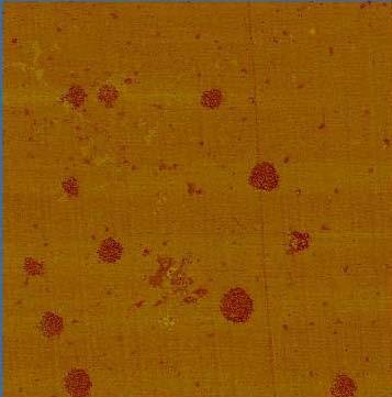
8 3.2.3 Toughness A fracture energy, G C, of 77 J/m 2 was measured for the unmodified epoxy polymer. The fracture energy was increased by the addition of silica nanoparticles, and a maximum G C, of 212 J/m 2 was measured for the epoxy containing 20 wt.% of silica, as shown in Table 1. (For completeness, the measured values of the fracture toughness, K C, are also shown in Table 1, and these data show similar trends to the fracture energies. However, the present discussion will concentrate on the fracture energies, as these can be most readily modelled and compared with the composite fracture data.) Considering the inclusion of the rubber toughener, the value of G C increases to 671 J/m 2 when 9 wt.% of CTBN-adduct is incorporated into the unmodified epoxy polymer, due to the toughening mechanisms induced by the presence of the rubber microparticles [10-11, 50]. The fracture energy increases further upon the formation of the hybrid materials, which contain both the rubber microparticles and silica nanoparticles. Indeed, the toughness of the hybrid epoxy polymer increases significantly as the concentration of the silica nanoparticles is increased, compared to the rubber-toughened epoxy polymer, as shown in Table 1. A maximum G C, of 965 J/m 2 was measured for the hybrid epoxy containing 15 wt.% of silica nanoparticles and 9 wt.% of rubber. However, when 9 wt.% rubber and 20 wt.% of silica nanoparticles are present, the measured fracture energy now decreases. For this hybrid epoxy polymer a relatively large amount of rubber, i.e. 3.5 wt.% of the 9 wt.% added as calculated using the Fox equation, does not phaseseparate. Notwithstanding, it should be noted there is a trend of steadily decreasing T g values as the silica nanoparticle content is increased, and this observation alone therefore does not account for such a large decrease in the fracture energy for this material. However, the AFM studies of the microstructure of the 20N9R hybrid epoxy polymer showed that the agglomerates of silica nanoparticles were much larger than those observed at lower nanoparticle concentrations. The structure of these agglomerates was also less necklace-like than was observed at the lower contents and in other work [37]. Indeed, transmission electron microscopy showed that these agglomerates were breaking-up during microtoming, which was not observed for the other hybrid polymers, and indicates that the agglomerates are relatively poorly bonded. Hence, it is concluded that the presence of these relatively large, and loosely-bonded, silica nanoparticle agglomerates leads to the reduction in the measured fracture energy for the 20N9R hybrid epoxy polymer Fractographic Studies The fracture surface of the unmodified epoxy polymer is relatively smooth and glassy, see Fig. 5a, which is typical of a brittle thermosetting polymer [6]. This shows that no large-scale plastic deformation has occurred during fracture, and agrees well with the relatively low value of the measured fracture energy. Feather markings are present, which are visible as steps and changes of the level of the crack. These are caused by crack forking due to the excess of energy associated with the rapid crack growth that occurs. This repeated forking, and the multi-planar nature of the surface, are ways of absorbing excess energy in a very brittle material [51]. Although the fracture energy was increased by the presence of silica nanoparticles, scanning electron microscopy of the fracture surfaces showed no significant differences as compared to the unmodified epoxy polymer, as shown in Fig. 5b. Indeed, the fracture surfaces of the epoxy polymers containing silica nanoparticles all have a brittle appearance and showed similar crack forking and feather markings to that of the unmodified epoxy polymer, see Fig. 5a. Now, the silica nanoparticles cannot be seen at the magnification of Fig. 5b due to their small diameter. However, high-resolution scanning electron microscopy (i.e. FEG-SEM) of a fracture surface of the epoxy containing 15 wt.% of silica nanoparticles clearly showed the presence of voids around the silica nanoparticles, as illustrated in Fig. 6. It is also noteworthy that not all of the silica nanoparticles appeared to debond to form voids. It should be noted that these voids are not an artefact of the coating process, which is used to prevent the sample charging during the electron microscopy investigations, as they were not observed on a coated fracture-surface of the unmodified epoxy [24]. The appearance of the voids was also independent of which coating material was used. Further, the voids were also observed using AFM of uncoated fracture-surfaces [24]. The toughening mechanisms for the silica nanoparticle-modified materials will be discussed in more detail below.
9 The addition of 9 wt.% of rubber to the epoxy gives a microstructure of dispersed rubber microparticles. Scanning electron microscopy of the fracture surfaces shows that these particles cavitate, see Fig. 5c, as has been well-described previously [50, 52-53]. This cavitation process is followed by plastic hole growth of the epoxy polymer, and the mean diameter of the cavitated rubber particles was measured to be 1.24 µm, with a coefficient of variation of ±0.46 µm, whereas their original mean diameter was approximately 0.54 µm. Compared with the unmodified epoxy polymer, i.e. with no dispersed rubber phase, the rubber particles greatly increase the toughness of the material, see Table 1, via interactions of the stress field ahead of the crack tip and the rubber particles, which leads to greatly enhanced plastic deformation of the epoxy polymer [54-56]. The hybrid materials, i.e. those with both rubber microparticles and silica nanoparticles, show relatively rough fracture surfaces, as would be expected from their relatively high fracture energies, see Table 1. Indeed, Fig. 5d shows evidence of cavitation of the rubber particles, though it is difficult to identify the mechanisms associated with the silica nanoparticles due to the roughness of the surfaces. However, high-resolution scanning-electron microscopy (FEG-SEM) studies of the hybrid fracture surfaces showed that the silica nanoparticles are present as both individual particles and agglomerates [36]. Cavities were observed around some of the silica nanoparticles, as was observed for the silica nanoparticle-modified epoxy polymers discussed above. In common with the polymers modified with silica nanoparticles only, not all of the silica nanoparticles debond from the epoxy in the hybrid epoxy polymers. 3.3 The Fibre-Composite Materials Toughness The measured values of the mode I interlaminar fracture energy, G C (composite), for the onset of crack growth for the various fibre-composites are shown in Tables 2 and 3. For the CFRP composites, the presence of the silica nanoparticles alone, at a concentration of 12 wt.%, had no significant effect on the interlaminar fracture energy, G C (composite). However, the addition of 9 wt.% of rubber alone does lead to an increase in the toughness of the CFRP composites from 439 to 1044 J/m 2. The further addition of silica nanoparticles to the rubbertoughened matrix, to form hybrid epoxy matrices, gives a further enhancement to the fracture energy, with a maximum value of G C (composite) of 1316 J/m 2 being recorded. The quasi-isotropic (QI) GFRP composites showed similar fracture energies to those of the CFRP. The addition of silica nanoparticles had little effect on the measured fracture energy. However, the rubber-modified composite showed a large increase in G C (composite), to 1035 J/m 2. A fracture energy of 1263 J/m 2 was measured for the QI GFRP composite which employed the hybrid epoxy matrix. For the unidirectional (UD) GFRP composites, a fracture energy of 330 J/m 2 was measured for the unmodified composite (i.e. the control material). The addition of 10 wt.% of silica nanoparticles to the unmodified epoxy matrix polymer gave a significant toughening effect, and a G C (composite) value of 1015 J/m 2 was measured. This is an increase of over 200% compared to the control composite. The GFRP composite with 9 wt.% of rubber in the epoxy matrix showed a significant increase in the fracture energy compared to the unmodified epoxy, a value of 885 J/m 2 being recorded. The addition of silica nanoparticles to the rubber-toughened epoxy, to give a hybrid epoxy matrix, gave a fracture energy of 860 J/m 2 for the composite material. Note that the increases in the fracture energy due to the presence of silica nanoparticles or rubber microparticles in the epoxy matrix, or the formation of hybrid epoxy matrices, are different for the different GFRP composites, and also when compared to the CFRP composites. This is due to (a) differences in the failure locus, i.e. whether the crack propagated through the composite matrix or at the fibre/matrix interface, and (b) the amount of fibre bridging. These aspects are discussed below.
10 3.3.2 Fractographic Studies The fracture surface of the CFRP with the unmodified epoxy matrix, see Fig. 7a, shows large areas of cohesive failure through the epoxy matrix. There is hardly any visible plastic deformation of the epoxy matrix, and the fracture surface is very similar to the fracture surface of the bulk, unmodified, epoxy polymer, see Fig. 5a. The micrograph in Fig. 7a shows evidence of good interfacial bonding between the fibres and the polymer, but some fibre debonding and pullout can be observed. However, the extent of fibre bridging is relatively limited due to the woven nature of the carbonfibre mats that were used. The presence of silica nanoparticles and/or rubber microparticles in the epoxy matrix has little effect on the appearance of the fracture surfaces taken at this low magnification, as shown in Figs. 7b, c and d. However, at relatively high magnifications, the CFRP composite containing 9 wt.% rubber showed evidence of cavitated rubber particles, as a large numbers of voids could be readily seen. At such magnifications, the fracture surfaces of the CFRP composites based on the hybrid epoxy matrix appeared similar to those based upon the rubbermodified epoxy matrix, in that rubber-particle cavitation was observed. For the UD GFRP composites, fibre-bridging was observed, and resistance curves (R-curves) were recorded. This was especially evident for the nanoparticle-modified composite. However, very little fibre bridging was observed for the UD GFRP composite which employed the hybrid epoxy matrix. The fracture surfaces of the QI GFRP composite with the unmodified matrix showed a brittle failure, with little visible plastic deformation of the epoxy polymer, see Fig. 8a. The fracture surfaces of the QI GFRP composite employing the matrix containing silica nanoparticles also exhibited a relatively brittle appearance, as shown in Fig. 8b. However, a relatively large extent of fibre bridging was observed, which accounts for the high interlaminar fracture energy values. The QI GFRP composite with 9 wt.% of rubber in the epoxy matrix showed a large numbers of voids in the matrix, see Fig. 8c. These cavities are up to 2 µm in diameter, revealing that the rubber particles have cavitated and this has enabled extensive plastic deformation and void growth of the epoxy matrix to occur. The surface of the glass fibres is relatively clean, indicating that the adhesion between the matrix and the fibres is relatively poor. When the hybrid matrix was employed, the composite fracture surfaces, shown in Fig. 8d, again reveal that the rubber particles have cavitated and that plastic deformation and void growth of the epoxy matrix has occurred. The agglomerated silica nanoparticles are also visible in Fig 8d. The adhesion between the fibres and the matrix appears better for the composite based upon the hybrid matrix than when the rubberonly matrix is employed, as a significant amount of epoxy matrix retained adhering to the fibres after fracture may be seen in Fig. 8d. 3.4 Composite versus Bulk Toughness To investigate whether the increases in the fracture energies of the bulk polymers due to the presence of silica nanoparticles and/or rubber microparticles are transferred to the composite, the composite fracture energies, G C (composite), may be plotted against the values, G C, for the corresponding bulk epoxy polymer, as shown in Fig. 9. Several noteworthy points arise from these data. Firstly, they show that the increased toughness, G C, of the epoxy polymer when used as the matrix for the fibre-composite is indeed transferred to give an increased interlaminar fracture energy, G C (composite), for the corresponding CFRP or GFRP composite. Secondly, the composite interlaminar fracture energies, G C (composite), are actually greater than the fracture energy, G C, of the corresponding epoxy polymer for all cases, except for one where the fracture energies are approximately equal in value. This observation arises since additional toughening mechanisms for the composites, such as fibre debonding, fibre pullout and fibre bridging, as discussed above, typically give a further increase in the value of G C (composite) compared to the value of G C. Thus, where little fibre bridging and pullout are observed, the composite fracture energy would be expected to be approximately equal to that of the epoxy polymer. This is in accord with the results shown in Fig. 9 and the above comments with respect to the unidirectional (UD) GFRP composite employing the hybrid epoxy matrix; where these
11 additional composite toughening mechanisms were observed to be absent, and this represents the one case where the fracture energies are approximately equal. Thirdly, the CFRP and quasi-isotropic (QI) GFRP composites generally show higher interlaminar fracture energies than the UD GFRP composites, which is probably due to the differences in the fibre architecture. Namely, the CFRP used woven fibre-mats, which lead to a relatively thick matrix layer between the fibre plies, and the cross-ply lay-up of the QI GFRP possessed similar resin-rich regions in the fracture plane. On the other hand, the UD GFRP possessed a unidirectional lay-up, with some stitching to hold the fibres in place, which leads to a thinner and less contiguous matrix layer between the fibre plies. In agreement with previous work of Hunston et al [57], the presence of the resin-rich matrix layers in the CFRP and QI GFRP would be expected to typically lead to these materials possessing higher values of G C (composite) compared to the UD GFRP composite, as was indeed observed. 4. The Toughening Mechanisms 4.1 Overview A previous study [24] has considered the toughening mechanisms induced by the silica nanoparticles in detail. The toughening mechanisms of (a) crack pinning, (b) crack deflection, and (c) immobilised polymer around the particles were all discounted. Instead, the ability of the silica nanoparticles to induce an increased extent of plastic deformation of the epoxy polymer was identified as the dominant toughening mechanism. The results of the present study are in complete agreement with this earlier work, and the two types of plastic deformation mechanisms in the epoxy polymer have been confirmed. These are (a) localised shear-bands initiated by the stress concentrations around the periphery of the silica nanoparticles, and (b) debonding of the silica nanoparticles followed by subsequent plastic void growth of the epoxy polymer. These two deformation mechanisms, both of which involve the epoxy polymer undergoing localised plastic deformation as a result of the silica nanoparticles being present in a process or plastic zone ahead of the crack tip, are discussed qualitatively below, and a quantitative model is then proposed in Section The Shear-Banding Mechanism An optical micrograph, taken between crossed polarisers, of an epoxy containing 11 wt.% of silica nanoparticles is shown in Fig. 10b. For clarity this is taken at the edge of the sample under planestress conditions, as the plastic zone under plane-strain conditions was too small to image satisfactorily. The corresponding conventional transmission optical-micrograph is shown in Fig. 10a. This excellent technique to obtain such micrographs was devised by Pearson and Yee [58] in order to help identify mechanisms occurring at crack tips. Fig. 10 shows clearly the plastic deformation that has occurred in the epoxy polymer immediately ahead of the crack tip. This micrograph is very similar to those shown by previous authors [33, 55, 59-60] for dispersed rubber microparticles in an epoxy polymer, but these particles were of the size of micrometres, as opposed to the present silica nanoparticles which have a radius of 10 nm. The birefringence of the plastically-deformed polymer in the micrograph in Fig. 10b reveals the plastic deformation that has occurred. The region closest to the fracture plane is relatively intense in nature, whilst the outermost regions clearly suggest that the deformation does occur in micro shear-bands, which appear to merge to form diffuse regions. The size of the plastic zone can be measured from these micrographs, and compared to theoretical predictions. The Irwin model states that the radius of the plastic zone, r y, can be calculated using [61]: r y = 1 EG C kπ σ2 y (7) where E is the Young s modulus, G C is the fracture energy, ν is the Poisson s ratio and σ y is the tensile yield stress of the polymer. The constant, k, has a value of k = 6(1-ν 2 ) for plane strain conditions, and k = 2 for plane stress. Substitution of the parameters for the epoxy, see Table 4,
12 with 11 wt.% of silica nanoparticles gives a predicted value of r y in plane strain of 4.8 μm, and a plane stress value of r y = 14.4 μm. Experimentally, it was not possible to measure the plane-strain value as the plastic zone was too small, as noted below. However, the value of r y measured in plane stress from the micrographs in Fig. 10 was 15 ±2 μm. This shows excellent agreement between the predicted and the experimental values. Similar very good agreement has been observed by Liang and Pearson in their recent work [18]. 4.3 The Plastic Void-Growth Mechanism The toughening mechanisms associated with rigid, e.g. silica, micrometre-sized particles have frequently been shown to be due to debonding of the particle followed by plastic void growth and shear yielding, e.g. [62-63]. Indeed, Kinloch and Taylor [6] have also demonstrated that the voids around such particles closed-up when the epoxy polymer was heated above its glass-transition temperature, T g, and allowed to relax. The debonding process is generally considered to absorb little energy compared to the plastic deformation of the epoxy polymer [64-65]. However, debonding is essential because this reduces the constraint at the crack tip, and hence allows the epoxy polymer to deform plastically via a void-growth mechanism. High-resolution scanning electron microscopy (FEG-SEM) of a fracture surface of the epoxy polymer containing 15 wt.% of silica nanoparticles, see Fig. 6, showed the presence of voids around many of the silica nanoparticles. This shows that plastic void-growth of the epoxy polymer, initiated by debonding of the silica nanoparticles, has occurred. The diameter of these voids is typically 30 nm. The voids were also observed in the fracture surfaces of samples with different concentrations of silica nanoparticles. Although the samples are coated to prevent charging in the electron microscope, the voids are not an artefact of the coating as they could not be observed on a coated fracture surface of the unmodified epoxy polymer [24]. Also the silica nanoparticlemodified epoxy samples appeared similar whether they were coated with platinum or gold. In addition, similar voids have been observed using AFM [24]. However, as may be clearly seen from Fig. 6, not all of the silica nanoparticles have debonded. This may arise (a) from the purely statistical aspect of the fracture process, or (b) from the fact that once a silica nanoparticle, or group of such particles, have debonded and the epoxy polymer started to undergo plastic void growth then the triaxial stress which drives such a mechanism is relieved in the adjacent region. The percentage of the silica nanoparticles which undergo such debonding (and subsequent void growth around them) has been counted, independently, by several of the present authors from micrographs such as that shown in Fig. 6. The estimated percentage of such silica nanoparticles is 15 ± 5% and, within the experimental scatter, this value is independent of the volume fraction of silica nanoparticles in the epoxy polymer. 5. Modelling Studies 5.1 Overview The experimental studies described in Section 4 above, and previous work [24-25], have led to the identification of two main toughening mechanisms associated with the increases in the value of the fracture energy, G C, when well-dispersed silica nanoparticles are present in the epoxy polymer. These mechanisms are (a) the generation of localised plastic shear-bands initiated by stress concentrations around the relatively high-modulus silica nanoparticles, and (b) the debonding of the silica nanoparticles from the epoxy polymer which then enables plastic void growth of the epoxy to occur. Now, these two toughening mechanisms are virtually identical to those which have been established [11, 50] for epoxy polymers toughened via the inclusion of rubber microparticles, which are typically about one to five micrometres in diameter. The one notable difference being that, prior to plastic void growth by the epoxy polymer, the silica nanoparticles debond at the silica/epoxy interface, whilst the rubber particles undergo internal cavitation, to produce the initial voids in the polymer [10, 52]. Thus, clearly, previous modelling studies by Huang and Kinloch [66-67] for rubber-particle toughened epoxy polymers are very relevant to the present studies on the silica nanoparticle modified-epoxy polymers. Hence, the following sections discuss the development of the Huang and Kinloch model for the present multiphase materials, followed by a comparison of the theoretical predictions to the experimental results.
13 5.2 The Basic Approach For the mechanisms of interest, Huang and Kinloch [67] proposed that the fracture energy, G C, may be expressed by: G C = G CU + Ψ (8) where G CU represents the fracture energy of the unmodified epoxy polymer and Ψ represents the overall toughening contributions activated by the presence of the particulate phase. Obviously Ψ contains the contributions from the two different toughening mechanisms and can be separated into two terms: Ψ = ΔG s + ΔG v (9) where ΔG S and ΔG V represent the contributions to the overall increase in the fracture energy, G C, from the localised plastic shear-banding and plastic void-growth mechanisms, respectively. 5.3 The Contribution from the Shear-Banding Mechanism Introduction The energy contribution, ΔG S, from the localised plastic shear-banding initiated by the presence of the particles is related to the size of the plastic zone and was calculated by Huang and Kinloch [67] from the following equation: ΔG s = 2 r y O U s (r)dr (10) where r y is the radius the plastic zone ahead of the crack tip and U s (r) is the dissipated strainenergy density for the shear-yielding mechanism. However, it has been suggested that the lower limit of integration in Eqn. 10 should not be zero. Instead, Evans et al [68] proposed that the lower limit of integration should be the minimum distance from the crack plane at which the epoxy polymer between the particles experiences plastic shear-yielding. This distance was suggested to be of the order of the particle radius, since a crack typically passes around one pole of the particle, leaving the plastically-deformed polymer at the opposite pole. Thus, Equation 10 now becomes: ΔG s = 2 r y rp U s (r)dr (11) where r p is the radius of the particle. According to the work of Dekkers and Heikens [69-70], shear bands will initiate from all of the particles Modelling the ΔG S Contribution With the lower integration limits of r p, instead of zero, the expression for the term ΔG S is as before: ΔG s = 0.5V f σ yc γ f F r y (12) where V f is the volume fraction of particles, σ yc and γ f are the plane-strain compressive yield stress and strain to fracture for the unmodified epoxy polymer, respectively. However, the term F / (r y ) is now somewhat modified from that given in the original formulation of the model in [67] to now be: F r y = r y (4π 3V f ) r p r y r p r y r p r y 7 5 r p r y 2 1 r p r y and where [67]: (13) r y = K 2 vm 1 + μ m r yu (14)
14 where K vm is the maximum stress concentration for the von Mises stresses around a rigid particle, µ m is a material constant which allows for the pressure-dependency of the yield stress [71] and r yu is the plastic zone size at fracture for the unmodified epoxy polymer. The value of K vm is dependent on the volume fraction of particles, and was calculated by fitting to the data of Guild and Young [72-73]. Its value varies from approximately 1.60 to 1.73 over the range of volume fractions used in the present work. The value of r yu may be readily calculated from [74]: r yu = 1 6π EG C (1 υ 2 )σ y 2 (15) where E, ν and σ y are the modulus, Poisson s ratio and tensile yield stress of the unmodified epoxy polymer, respectively. As will be shown below, all the parameters in Eqns. 12 to 15 may be measured or directly calculated. Thus, the contribution ΔG S may be readily ascertained. 5.4 Modelling the ΔG V Contribution The modelling studies of Huang and Kinloch give the contribution ΔG V to the toughness from the plastic void growth mechanism as: G v = (1 μ 2 2 m /3) V fv V fp σ yc r yu K vm (16) where V fv and V fp are the volume fraction of voids and the volume fraction of particles which debond, respectively. The terms V fv and V fp may be directly measured from the appropriate electron micrographs, and the value of r yu may be calculated from Eqn Application of the Model The value of Ψ may now be evaluated from Eqns. 12 and 16 to give, via Eqn. 9: Ψ = 0.5V f σ yc γ f F r y + (1 μ 2 2 m /3) V fv V fp σ yc r yu K vm (17) where the term F / (r y ) is defined in Eqns. 13 and 14, the term r yu is defined in Eqn. 15, and where K vm is the maximum stress concentration for the von Mises stresses around a void. The value of K vm has been calculated by Huang and Kinloch [66-67] and varies with volume fraction in the range 2.11 to 2.12 for the volume fractions considered in the present work. The model may now be applied to the epoxy polymers containing the silica nanoparticles. The various parameters needed for the model are shown in Table 4. From the values of the parameters given in Table 4 and the above equations the contributions ΔG S and ΔG V to the localised plastic shear-banding and plastic void-growth mechanisms in the silica nanoparticle epoxy may be calculated. Hence, the value of the fracture energy, G C, of the epoxy polymers may be predicted. The predicted values are compared to the experimentally measured values in Table 5 and, as may be observed, there is very good agreement between the measured values and those predicted from the equations developed above from the earlier Huang and Kinloch model [67]. Indeed, this good agreement is especially noteworthy when the lack of any adjustable fitting terms in the above equations is considered. It is also noteworthy that the void size measured from the high-resolution electron micrographs can be compared to values calculated from considering the maximum hoop strain around the particles. If the fracture strain measured from the plane-strain compression tests, i.e. a true strain of 0.75, is equated with the maximum hoop strain around the void, then a final void diameter of 35 nm is predicted. This compares very well with the mean diameter of 30 nm which was measured from the micrographs.
15 5.6 Comparison of Nano- and Micrometre-Sized Silica Particles Now there is an extensive literature e.g. [63, 75] concerning the effect on the fracture energy, G C, of epoxy polymers arising from the addition of spherical silica (i.e. glass) particles of the order of a few to tens of micrometres in diameter. From these previous studies, the research by Spanoudakis and Young [2] employed an unmodified epoxy polymer with a very similar fracture energy to that of the unmodified epoxy polymer employed in the present studies. Therefore, a comparison of the results from these authors and the present results for the silica nanoparticle-modified material, at a volume fraction of silica of approximately 0.11, is given in Table 6. There is clearly a progressive increase in the toughness, G C, as the radius, r p, of the silica particle is steadily reduced. Further, the model developed above, and stated in Eqns. 15 and 17, has been employed to predict the toughness ratio (i.e. G C (silica epoxy)/g C (epoxy)) for all the silica-particle modified epoxy polymers. Since the exact values of the various input parameters needed for the modelling studies of the micrometre-sized silica particles are not known, the values given in Table 4 have been employed. (It is recognised that this is an approximation and that the predicted values of G C for these modified epoxy polymers may therefore only be considered approximate in value. However, the value of V fp was taken to be equivalent to V f for the micrometre-sized glass particles, as suggested from the original papers.) Notwithstanding, the predicted values of the toughness ratios not only show a similar trend to the measured ratios but also are in very reasonable quantitative agreement, as may be seen from Table 6. Again, it should be emphasised that there are no fitting terms in the equations employed in the present modelling studies. It should be noted that the model developed here does not include any contribution to the toughness of the silica-particle modified epoxy-polymer from the effect of crack deflection, which may occur when the particle diameter is much larger than the size of the plastic zone as discussed by Green et al [76] and Faber and Evans [77]. For the nanoparticles used in the present work this is not the case, as argued by Johnsen et al [24]. However, crack deflection may apply for the microparticles used by Spanoudakis and Young [2], but such a contribution will be relatively low. 5.7 Synergy in the Hybrid Epoxy Polymers The hybrid epoxy polymers contain both silica nanoparticles and rubber microparticles, as shown earlier in Fig. 5. Further, the values of the fracture energy, G C, for these hybrid polymers were given earlier in Table 1. From these values it is clearly evident that the presence of both types of particles gives rise to a synergetic effect with respect to the value of G C for these materials. For example, for the hybrid epoxy polymer containing 2.3 wt.% of silica nanoparticles and 9 wt.% of rubber, the measured fracture energy, G C, is 720 J/m 2, whilst if the effect of each type of particle was merely additive then this would give an expected G C value of 695 J/m 2. Similarly, using 10 wt.% of silica nanoparticles and 9 wt.% of rubber to form the hybrid epoxy polymer, the measured G C value is 906 J/m 2, whilst the individual contributions from both these types of tougheners would be simply summed to give 775 J/m 2. Finally, for the 15 wt.% of silica nanoparticles and 9 wt.% of rubber, the measured G C value is 965 J/m 2, whilst a solely additive effect would be expected to give a value of 790 J/m 2. Obviously, a question that the above observations raise is why the two types of particles, i.e. silica nanoparticles and rubber microparticles interact to give this synergetic increase in the measured toughness. The most likely explanation is that interactions may occur between such particles of very different moduli, Poisson s ratio and size in the stress field immediately ahead of a crack to give an enhanced degree of plastic deformation. Indeed, it has been previously established that such stress-field interactions may enhance the extent of the plastic zone and the intensity of the plastic-deformation mechanisms [33, 59, 78-79]. Alternatively, although it is assumed that shear bands will initiate from all of the particles [69-70], the cavitation of the rubber particles may allow the silica nanoparticles to initiate more extensive or intense shear banding, thus increasing the contribution of shear banding to the overall toughness.
16 6. Conclusions The structure/property relationship of an anhydride-cured epoxy modified with silica nanoparticles and/or rubber microparticles has been investigated. Microscopy showed that the silica nanoparticles were well-dispersed in the epoxy. However, in the hybrid epoxy-polymer, which contained both silica nanoparticles and rubber microparticles, some agglomeration of the silica nanoparticles was observed. The fracture energy, G C, of the bulk epoxy was increased from 77 to 212 J/m 2 by the addition of 20 wt.% silica nanoparticles. The observed toughening mechanisms were debonding of the epoxy polymer from the silica nanoparticles, followed by plastic void growth of the epoxy. Localised plastic shear-banding in the polymer was also observed. The largest increases in toughness were from the formation of the hybrid epoxy polymers, which contained both silica nanoparticles and rubber microparticles, and here a maximum fracture energy of 965 J/m 2 was measured. The increases in the toughness of the bulk epoxy polymers were transferred to the fibre composites; and the interlaminar fracture energy, G C (composite), of the fibre-composites was typically even further enhanced by fibre bridging, fibre debonding and fibre pullout mechanisms coming into play for the composite materials. An existing model has been extended to predict the toughening effect of silica nanoparticles in a thermoset polymer to include the effects of shear banding, as well as plastic void growth of the epoxy polymer. There was excellent agreement between the predictions and the experimental data for the epoxy polymer containing silica nanoparticles. This model has also been used to predict the toughness of an epoxy containing micrometre-sized glass particles, and again good agreement was observed compared to the experimental data. Finally, both the theoretical and experimental studies clearly reveal the benefits of using silica nanoparticles, as opposed to much larger micrometre-sized silica particles, in terms of observing a relatively high toughness for the modified epoxy polymer. Acknowledgements The authors would like to thank the EPSRC for a doctoral training award for Mr. Masania. They would also like to acknowledge the general support of Emerald Performance Materials, Henkel, Nanoresins and the US Army European Research Office. Some of the equipment used was provided by Dr. Taylor s Royal Society Mercer Junior Award for Innovation. References [1] LJ Broutman, S Sahu (1971) Mater. Sci. Eng. 8: 98. [2] J Spanoudakis, RJ Young (1984) J. Mater. Sci. 19: 473. [3] LM McGrath, RS Parnas, JL Lenhart, S King (2006) Polym. Mater. Sci. Eng. 94: 683. [4] R Griffiths, D Holloway (1970) J. Mater. Sci. 5: 302. [5] DG Dixon, SJ Harris, M Dempster, P Nicholls (1998) J. Adhesion 65: 131. [6] AJ Kinloch, AC Taylor (2002) J. Mater. Sci. 37: 433. [7] K-F Lin, Y-D Shieh (1998) J. Appl. Polymer Sci. 70: [8] DS Kim, K Cho, JK Kim, CE Park (1996) Polym. Eng. Sci. 36: 755. [9] RS Drake, AR Siebert (1975) SAMPE Quarterly 6: 11. [10] AJ Kinloch, SJ Shaw, DA Tod, DL Hunston (1983) Polymer 24: [11] AF Yee, RA Pearson (1986) J. Mater. Sci. 21: [12] CB Bucknall, IK Partridge (1983) Polymer 24: 639. [13] AJ Kinloch, ML Yuen, SD Jenkins (1994) J. Mater. Sci. 29: [14] CB Bucknall, AH Gilbert (1989) Polymer 30: 213. [15] BB Johnsen, AJ Kinloch, AC Taylor (2005) Polymer 46: [16] AJ Kinloch, CA Finch, S Hashemi (1987) Polymer Comm. 28: 322. [17] RA Pearson, AF Yee (1989) J. Mater. Sci. 24: 2571.
17 [18] YL Liang, RA Pearson (2009) Polymer 50: [19] JK Kim, C Baillie, J Poh, YW Mai (1992) Composites Sci. Tech. 43: 283. [20] MD Gilchrist, N Svensson (1995) Composites Sci. Tech. 55: 195. [21] AJ Kinloch, RD Mohammed, AC Taylor, S Sprenger, D Egan (2006) J. Mater. Sci. 41: [22] AJ Kinloch, JH Lee, AC Taylor, S Sprenger, C Eger, D Egan (2003) J. Adhesion 79: 867. [23] BRK Blackman, AJ Kinloch, J Sohn Lee, AC Taylor, R Agarwal, G Schueneman, S Sprenger (2007) J. Mater. Sci. 42: [24] BB Johnsen, AJ Kinloch, RD Mohammed, AC Taylor, S Sprenger (2007) Polymer 48: 530. [25] AJ Kinloch, RD Mohammed, AC Taylor, C Eger, S Sprenger, D Egan (2005) J. Mater. Sci. 40: [26] BS-EN-2564 (1998) Carbon fibre laminates - Determination of the fibre, resin and void contents. BSI, London. [27] BS-EN-ISO (1996) Plastics - Determination of Tensile Properties - Part 2: Test Conditions for Moulding and Extrusion Plastics. BSI, London. [28] JG Williams, H Ford (1964) J. Mech. Eng. Sci. 6: 405. [29] ISO (2000) Plastics-Determination of Fracture Toughness (G IC and K IC ) - Linear Elastic Fracture Mechanics (LEFM) Approach. ISO, Geneva. [30] ASTM-D5528 (2001) Standard Test Method for Mode I Interlaminar Fracture Toughness of Unidirectional Fiber-Reinforced Polymer Matrix Composites. ASTM, West Conshohocken. [31] HJ Sue (1991) Polym. Eng. Sci. 31: 270. [32] HJ Sue, AF Yee (1993) J. Mater. Sci. 28: [33] RA Pearson, AF Yee (1991) J. Mater. Sci. 26: [34] J Baller, N Becker, M Ziehmer, M Thomassey, B Zielinski, U Müller, R Sanctuary (2009) Polymer 50: [35] TG Fox (1956) Bull. Am. Phys. Soc. 1: 123. [36] RD Mohammed (2007) PhD in Mechanical Engineering, Imperial College of Science, Technology & Medicine: London. [37] JH Lee (2006) PhD in Mechanical Engineering, Imperial College of Science, Technology & Medicine: London. [38] (2005) Goodfellow Product Catalogue. Goodfellow, Huntingdon. [39] KJ Pascoe (1978) An introduction to the properties of engineering materials. Van Nostrand Reinhold, London. [40] EH Kerner (1956) Proc. Phys. Soc. B 69: 808. [41] LE Nielsen (1966) J. Appl. Polymer Sci. 10: 97. [42] JC Halpin, NJ Pagano (1969) J. Composite Mater. 3: 720. [43] JC Halpin (1969) J. Composite Mater. 3: 732. [44] JC Halpin, JL Kardos (1976) Polym. Eng. Sci. 16: 344. [45] PHT Vollenberg, D Heikens (1989) Polymer 30: [46] TB Lewis, LE Nielsen (1970) J. Appl. Polymer Sci. 14: [47] S McGee, RL McCullough (1981) Polymer Composites 2: 149. [48] LE Nielsen, RF Landel (1994) Mechanical properties of polymers and composites. Marcel Dekker, New York. [49] LE Nielsen (1968) J. Composite Mater. 2: 120. [50] RA Pearson, AF Yee (1986) J. Mater. Sci. 21: [51] EH Andrews (1968) Fracture in Polymers. Oliver & Boyd, Edinburgh. [52] AJ Kinloch (1986) in Kinloch AJ (ed) Structural Adhesives - Developments in Resins and Primers. Applied Science Publishers, London. [53] J Karger-Kocsis, K Friedrich (1992) Colloid Polymer Sci. 270: 549. [54] C Cheng, A Hiltner, E Baer, PR Soskey, SG Mylonakis (1995) J. Mater. Sci. 30: 587. [55] HR Azimi, RA Pearson, RW Hertzberg (1996) Polym. Eng. Sci. 36: [56] TK Chen, YH Jan (1992) J. Mater. Sci. 27: 111. [57] DL Hunston, RJ Moulton, NJ Johnston, WD Bascom (1985) in Johnston NJ (ed) Toughened composites. ASTM, Philadelphia, USA. [58] J Vega-Baudrit, M Sibaja-Ballestero, P Vazquez, R Torregrosa-Macia, JM Martin-Martinez (2007) Int. J. Adhesion Adhesives 27: 469.
18 [59] R Bagheri, RA Pearson (1996) J. Mater. Sci. 31: [60] R Bagheri, RA Pearson (1995) J. Appl. Polymer Sci. 58: 427. [61] RM Caddell (1980) Deformation and Fracture of Solids. Prentice-Hall, Englewood Ciffs, New Jersey. [62] J Lee, AF Yee (2000) Polymer 41: [63] T Kawaguchi, RA Pearson (2003) Polymer 44: [64] AJ Kinloch (1987) Adhesion and Adhesives : Science and Technology. Chapman & Hall, London. [65] DA Norman, RE Robertson (2003) Polymer 44: [66] Y Huang, AJ Kinloch (1992) J. Mater. Sci. 27: [67] Y Huang, AJ Kinloch (1992) J. Mater. Sci. 27: [68] AG Evans, S Williams, PWR Beaumont (1985) J. Mater. Sci. 20: [69] MEJ Dekkers, D Heikens (1984) J. Mater. Sci. 19: [70] MEJ Dekkers, D Heikens (1985) J. Mater. Sci. 20: [71] JN Sultan, FJ McGarry (1973) Polym. Eng. Sci. 13: 29. [72] FJ Guild, RJ Young (1989) J. Mater. Sci. 24: 298. [73] FJ Guild, RJ Young (1989) J. Mater. Sci. 24: [74] AJ Kinloch, RJ Young (1983) Fracture Behaviour Of Polymers. Applied Science Publishers, London. [75] J Lee, AF Yee (2000) Polymer 41: [76] DJ Green, PS Nicholson, JD Embury (1979) J. Mater. Sci. 14: [77] KT Faber, AG Evans (1983) Acta Metallurgica 31: 565. [78] CJ Sun, P Saffari, K Sadeghipour, G Baran (2005) Materials Science and Engineering: A 405: 287. [79] B Pukanszky, G Voros (1996) Polymer Composites 17: 384.
19 Tables Table 1. Glass transition temperature, Young s modulus, fracture toughness and fracture energy of the epoxy polymer formulations. wt.% silica wt.% CTBN Name T g DMTA E ( C) (GPa) K C (MPam 1/2 ) G C (J/m 2 ) 0 0 Control N N N N N N9R N9R N9R n/d n/d 9 9 9N9R N9R N9R N9R Note: Typical coefficients of variation for the fracture data are ±10% for the xn formulations, and ±15% for the hybrid (xnyr) formulations. Table 2. Fracture energies of the carbon-fibre (CFRP) composites. Formulation G C (composite) (J/m 2 ) Name wt.% silica wt.% CTBN Mean σ Control N R N9R N9R N9R N9R
20 Table 3. Fracture energies of the unidirectional (UD) and quasi-isotropic (QI) glass-fibre (GFRP) composites. Formulation G C (composite) UD (J/m 2 ) G C (composite) QI (J/m 2 ) Name wt% silica wt% CTBN Mean σ Mean σ Control N R N9R Table 4. The parameters, and their values, used in the modelling studies. Name Symbol Unit Value Source Radius of the silica nanoparticles r p nm 10 [24] Volume fraction of the nanoparticles V f - See Table 5 Present study Volume fraction of the particles which debond and void V fp V f Present study Radius of voids around the debonded nanoparticles r pv nm 15 [24] Tensile modulus E GPa 2.96 [24] Poisson s ratio ν [64] Plane-strain compressive yield stress σ yc MPa 120 Present study Plane-strain compressive fracture strain (true strain) γ f Present study Uniaxial tensile yield stress σ y MPa 88 Present study Pressure-dependent yield stress parameter μ m [71] Fracture energy G C J/m 2 77 Present study Note: All mechanical properties are for the unmodified (i.e. control) epoxy polymer.
21 Table 5. Comparison of the measured and predicted values of the fracture energy, G C, as a function of the volume fraction, V f, of silica nanoparticles in the epoxy polymer. Silica content (wt.%) Silica content, V f ΔG s value (J/m 2 ) ΔG v value (J/m 2 ) G C predicted (J/m 2 ) G C measured (J/m 2 ) Table 6. Comparison of the relative fracture energy of epoxy polymers containing a volume fraction, V f, of approximately 0.11 as a function of the radius, r p, of the silica particles. Radius, r p, of silica particle (µm) G C (silica epoxy) / G C (epoxy) Measured 1-3 Predicted Notes: 1. G C values for r p = 10 nm from Table G C values for r p = 8, 16 and 23 µm from Spanoudakis and Young [2]. 3. G C of the epoxy polymer used in [2] was 80 J/m Predicted values for all values of r p from Equations 7 and 15.
22 List of Figure Captions Figure 1. AFM images of the microstructure of epoxy polymers: (a) unmodified, (b) with 11 wt.% silica nanoparticles, (c) with 9 wt.% CTBN, (d) with 10 wt.% silica nanoparticles and 9 wt.% CTBN, (e) with 15 wt.% silica nanoparticles and 9 wt% CTBN, and (f) with 20 wt.% silica nanoparticles and 9 wt.% CTBN. Figure 2. Dynamic mechanical analysis data for a hybrid epoxy polymer containing: 10 wt.% silica nanoparticles and 9 wt.% CTBN. Figure 3. Transmission electron micrographs of hybrid epoxy polymers containing: (a) 2.3 wt.% silica nanoparticles and 9 wt.% CTBN, and (b) 15 wt.% silica nanoparticles and 9 wt.% CTBN. Figure 4. Relative modulus versus content of silica nanoparticles, for the silica nanoparticle modified epoxy polymers and the hybrid (i.e. with CTBN rubber also present) epoxy polymers. Points are experimental data, lines are theoretical predictions. Figure 5. Scanning electron micrographs of fracture surfaces of epoxy polymers: (a) unmodified, (b) with 15 wt.% silica nanoparticles, (c) with 9 wt.% CTBN, and (d) with 4.5 wt.% silica nanoparticles and 9 wt.% CTBN. (Crack propagation is from bottom to top.) Figure 6. High-resolution scanning electron micrograph of fracture surface of an epoxy polymer containing 15 wt.% silica nanoparticles. (Some voids around silica nanoparticles are circled.) Figure 7. Scanning electron micrographs of fracture surfaces of CFRP composites employing an epoxy matrix: (a) unmodified, (b) with 12 wt.% silica nanoparticles, (c) with 9 wt.% CTBN, and (d) with 10 wt.% silica nanoparticles and 9 wt.% CTBN. (Crack propagation is from left to right.) Figure 8. Scanning electron micrographs of fracture surfaces of quasi-isotropic (QI) GFRP composite employing an epoxy matrix: (a) unmodified, (b) with 10 wt.% silica nanoparticles, (c) with 9 wt.% CTBN, and (d) with 10 wt.% silica nanoparticles and 9 wt.% CTBN. Figure 9. Interlaminar fracture energy, G C (composite), for the composite versus the corresponding bulk fracture energy, G C, for the epoxy polymer. (The 1:1 line is shown to merely aid visual interpretation of the data.) Black-filled symbols are for CFRP; unfilled symbols are for unidirectional (UD) GFRP; and greyfilled symbols are for quasi-isotropic (QI) GFRP. Unmodified epoxy polymer (i.e. control): ; with silica nanoparticles: ; with CTBN: ; hybrid :.
23 Figure 10. Transmission optical-micrographs of an epoxy polymer with 11 wt.% silica nanoparticles, showing the plane-stress region taken using (a) normal light, and (b) between crossed polarisers. (Crack propagation is from left to right.)


24 1μm 0.5μm 1μm

 with 9 wt.")

25 1μm 1μm 1μm Figure 1. AFM images of the microstructure of epoxy polymers: (a) unmodified, (b) with 11 wt.% silica nanoparticles, (c) with 9 wt.% CTBN, (d) with 10 wt.% silica nanoparticles and 9 wt.% CTBN, (e) with 15 wt.% silica nanoparticles and 9 wt.% CTBN, and (f) with 20 wt.% silica nanoparticles and 9 wt.% CTBN.

 15 wt.% silica nanoparticles and 9 wt.% CTBN.")
26 log G' (Pa) log G' tan delta Tan Delta Temperature ( o C) Figure 2. Dynamic mechanical analysis data for a hybrid epoxy polymer containing 10 wt.% silica nanoparticles and 9 wt.% CTBN. (a) (b) Figure 3. Transmission electron micrographs of hybrid epoxy polymers containing: (a) 2.3 wt.% silica nanoparticles and 9 wt.% CTBN, and (b) 15 wt.% silica nanoparticles and 9 wt.% CTBN.
27 Relative Modulus, E/E U Silica nanoparticle polymers 'Hybrid' polymers Halpin-Tsai Nielsen no slip Nielsen interfacial slip Silica Nanoparticle content, wt% Figure 4. Relative modulus versus content of silica nanoparticles, for the silica nanoparticle modified epoxy polymers and the hybrid (i.e. with CTBN rubber also present) epoxy polymers. Points are experimental data, lines are theoretical predictions.

 unmodified, (b) with")
 with 9")

28 (a) (b) (c) (d) Figure 5. Scanning electron micrographs of fracture surfaces of epoxy polymers: (a) unmodified, (b) with 15 wt.% silica nanoparticles, (c) with 9 wt.% CTBN, and (d) with 4.5 wt.% silica nanoparticles and 9 wt.% CTBN. (Crack propagation is from bottom to top.)

29 200 nm Figure 6. High-resolution scanning electron micrograph of fracture surface of epoxy polymer containing 15 wt.% silica nanoparticles. (Some voids around silica nanoparticles are circled.)

")
 with 9 wt.")

30 (a) (b) (c) (d) Figure 7. Scanning electron micrographs of fracture surfaces of CFRP composites employing an epoxy matrix: (a) unmodified, (b) with 12 wt.% silica nanoparticles, (c) with 9 wt.% CTBN, and (d) with 10 wt.% silica nanoparticles and 9 wt.% CTBN. (Crack propagation is from left to right.)

 GFRP")
 unmodified, (b) with")
 with 9")
31 (a) (b) (c) (d) Figure 8. Scanning electron micrographs of fracture surfaces of quasi-isotropic (QI) GFRP composite employing an epoxy matrix: (a) unmodified, (b) with 10 wt.% silica nanoparticles, (c) with 9 wt.% CTBN, and (d) with 10 wt.% silica nanoparticles and 9 wt.% CTBN.
32 Hybrid G C (composite), J/m Silica nanoparticles CTBN Control G C (bulk), J/m 2 Figure 9. Interlaminar fracture energy, G C (composite), for the composite versus the corresponding bulk fracture energy, G C, for the epoxy polymer. (The 1:1 line is shown to merely aid visual interpretation of the data shown.) Black-filled symbols are for CFRP; unfilled symbols are for unidirectional (UD) GFRP; and greyfilled symbols are for quasi-isotropic (QI) GFRP. Unmodified epoxy polymer (i.e. control): ; with silica nanoparticles: ; with CTBN: ; hybrid :.


33 Figure 10. Transmission optical-micrographs of an epoxy polymer with 11 wt.% silica nanoparticles, showing the plane-stress region taken using (a) normal light, and (b) between crossed polarisers. (Crack propagation is from left to right.)
Department of Mechanical Engineering, Imperial College London, London SW7 2AZ, UK
 5 th Australasian Congress on Applied Mechanics, ACAM 2007 10-12 December 2007, Brisbane, Australia Toughening mechanisms in novel nano-silica epoxy polymers A.J. Kinloch 1, B.B. Johnsen 1, R.D. Mohammed
Toughened carbon fibre-reinforced polymer composites with nanoparticle-modified epoxy matrices
 J Mater Sci (2017) 52:1767 1788 Toughened carbon fibre-reinforced polymer composites with nanoparticle-modified epoxy matrices D. Carolan 1,2, *, A. Ivankovic 2, A. J. Kinloch 1, S. Sprenger 3, and A.
A SELF-INDICATING MODE I INTERLAMINAR TOUGHNESS TEST
 A SELF-INDICATING MODE I INTERLAMINAR TOUGHNESS TEST P. Robinson The Composites Centre, Department of Aeronautics, Imperial College London South Kensington, London, SW7 2AZ, UK p.robinson@imperial.ac.uk
Non-conventional Glass fiber NCF composites with thermoset and thermoplastic matrices. F Talence, France Le Cheylard, France
 20 th International Conference on Composite Materials Copenhagen, 19-24th July 2015 Non-conventional Glass fiber NCF composites with thermoset and thermoplastic matrices. Thierry Lorriot 1, Jalal El Yagoubi
ISSN: ISO 9001:2008 Certified International Journal of Engineering Science and Innovative Technology (IJESIT) Volume 2, Issue 4, July 2013
 Volume 2, Issue 4, July 2013") Delamination Studies in Fibre-Reinforced Polymer Composites K.Kantha Rao, Dr P. Shailesh, K. Vijay Kumar 1 Associate Professor, Narasimha Reddy Engineering College Hyderabad. 2 Professor, St. Peter s Engineering
Delamination Studies in Fibre-Reinforced Polymer Composites K.Kantha Rao, Dr P. Shailesh, K. Vijay Kumar 1 Associate Professor, Narasimha Reddy Engineering College Hyderabad. 2 Professor, St. Peter s Engineering
MODELLING INTERACTION EFFECT OF NANOSILICA PARTICLES ON NANOSILICA/EPOXY COMPOSITE STIFFNESS
 MODELLING INTERACTION EFFECT OF NANOSILICA PARTICLES ON NANOSILICA/EPOXY COMPOSITE STIFFNESS Mulyadi a*, I. Gitman a, C. Pinna a, C. Soutis b a Department of Mechanical Engineering, The University of Sheffield,
CHEM-E2200: Polymer blends and composites Fibre architecture and principles of reinforcement
 CHEM-E2200: Polymer blends and composites Fibre architecture and principles of reinforcement Mark Hughes 19 th September 2016 Outline Fibre architecture Volume fraction and the rule of mixtures Principle
MODE I AND MODE II FRACTURE BEHAVIOUR OF CARBON/GLASS HYBRID FILAMENT-WOUND RESIN TRANSFER MOULDED COMPOSITES
 MODE I AND MODE II FRACTURE BEHAVIOUR OF CARBON/GLASS HYBRID FILAMENT-WOUND RESIN TRANSFER MOULDED COMPOSITES J. M. Taylor a*, S. Frenz b, C. Canturri c, S. Giannis b, E. S. Greenhalgh c a Rolls-Royce
Computational Analysis for Composites
 Computational Analysis for Composites Professor Johann Sienz and Dr. Tony Murmu Swansea University July, 011 The topics covered include: OUTLINE Overview of composites and their applications Micromechanics
Mechanical Properties of Epoxy/Al 2 O 3 Nanocomposites
 Mechanical Properties of Epoxy/Al 2 O 3 Nanocomposites M. J. Kadhim*, A. K. Abdullah, I. A. Al-Ajaj, and A. S. Khalil Department of Physics, College of Science, Baghdad University, Baghdad, Iraq. Abstract
DEVELOPMENT OF THERMOELASTIC STRESS ANALYSIS AS A NON-DESTRUCTIVE EVALUATION TOOL
 DEVELOPMENT OF THERMOELASTIC STRESS ANALYSIS AS A NON-DESTRUCTIVE EVALUATION TOOL S. Quinn*, R.K. Fruehmann and J.M. Dulieu-Barton School of Engineering Sciences University of Southampton Southampton SO17
Project MMS13 Task 5 Report No 3 (M6/D3)
") Project MMS13 Task 5 Report No 3 (M6/D3) Material Data Requirements and Recommended Test Methods for the Predictive Modelling of Defect Criticality in Composite Material Systems M R L Gower and G D Sims
Project MMS13 Task 5 Report No 3 (M6/D3) Material Data Requirements and Recommended Test Methods for the Predictive Modelling of Defect Criticality in Composite Material Systems M R L Gower and G D Sims
CHEM-C2410: Materials Science from Microstructures to Properties Composites: basic principles
 CHEM-C2410: Materials Science from Microstructures to Properties Composites: basic principles Mark Hughes 14 th March 2017 Today s learning outcomes To understand the role of reinforcement, matrix and
Fig. 1. Different locus of failure and crack trajectories observed in mode I testing of adhesively bonded double cantilever beam (DCB) specimens.
 specimens.") a). Cohesive Failure b). Interfacial Failure c). Oscillatory Failure d). Alternating Failure Fig. 1. Different locus of failure and crack trajectories observed in mode I testing of adhesively bonded double
a). Cohesive Failure b). Interfacial Failure c). Oscillatory Failure d). Alternating Failure Fig. 1. Different locus of failure and crack trajectories observed in mode I testing of adhesively bonded double
Graphene nanoplatelet-modified epoxy: Effect of aspect ratio and surface functionality on mechanical properties and toughening mechanisms
 Graphene nanoplatelet-modified epoxy: Effect of aspect ratio and surface functionality on mechanical properties and toughening mechanisms H. M. Chong a,c, S. J. Hinder b, A. C. Taylor a, a Department of
Most of the material in this package is based on a recently published book. This is:
 Mechanics of Composite Materials Version 2.1 Bill Clyne, University of Cambridge Boban Tanovic, MATTER Assumed Pre-knowledge It is assumed that the student is familiar with simple concepts of mechanical
NUMERICAL INVESTIGATION OF DELAMINATION IN L-SHAPED CROSS-PLY COMPOSITE BRACKET
 NUMERICAL INVESTIGATION OF DELAMINATION IN L-SHAPED CROSS-PLY COMPOSITE BRACKET M.Gümüş a*, B.Gözlüklü a, D.Çöker a a Department of Aerospace Eng., METU, Ankara, Turkey *mert.gumus@metu.edu.tr Keywords:
THE ROLE OF DELAMINATION IN NOTCHED AND UNNOTCHED TENSILE STRENGTH
 THE ROLE OF DELAMINATION IN NOTCHED AND UNNOTCHED TENSILE STRENGTH M. R. Wisnom University of Bristol Advanced Composites Centre for Innovation and Science University Walk, Bristol BS8 1TR, UK M.Wisnom@bristol.ac.uk
MICROMECHANICAL DEFORMATIONS IN PARTICULATE FILLED POLYMERS: THE EFFECT OF ADHESION
 MICROMECHANICAL DEFORMATIONS IN PARTICULATE FILLED POLYMERS: THE EFFECT OF ADHESION K. Renner, J. Móczó, B. Pukánszky Laboratory of Plastics and Rubber Technology, Department of Physical Chemistry and
A CRITERION OF TENSILE FAILURE FOR HYPERELASTIC MATERIALS AND ITS APPLICATION TO VISCOELASTIC-VISCOPLASTIC MATERIALS
 MTS ADHESIVES PROGRAMME 1996-1999 PERFORMANCE OF ADHESIVE JOINTS Project: PAJ1; Failure Criteria and their Application to Visco-Elastic/Visco-Plastic Materials Report 2 A CRITERION OF TENSILE FAILURE FOR
Finite element modelling of infinitely wide Angle-ply FRP. laminates
 www.ijaser.com 2012 by the authors Licensee IJASER- Under Creative Commons License 3.0 editorial@ijaser.com Research article ISSN 2277 9442 Finite element modelling of infinitely wide Angle-ply FRP laminates
SCALING EFFECTS IN THE LOW VELOCITY IMPACT RESPONSE OF FIBRE METAL
 SCALING EFFECTS IN THE LOW VELOCITY IMPACT RESPONSE OF FIBRE METAL LAMINATES J. G. Carrillo 1, S. McKown 1, M. Mujib 1 and W. J. Cantwell 1. R. Day 2 1 Department of Engineering, University of Liverpool,
Module 4: Behaviour of a Laminae-II. Learning Unit 1: M1. M4.1 Mechanics of Composites. M4.1.1 Introduction to Mechanics of Composites
 Module 4: Behaviour of a Laminae-II Learning Unit 1: M1 M4.1 Mechanics of Composites M4.1.1 Introduction to Mechanics of Composites The relation between ply uniaxial strengths and constituent properties
The Effects of Transverse Shear on the Delamination of Edge-Notch Flexure and 3-Point Bend Geometries
 The Effects of Transverse Shear on the Delamination of Edge-Notch Flexure and 3-Point Bend Geometries M. D. Thouless Department of Mechanical Engineering Department of Materials Science & Engineering University
SOME RESEARCH ON FINITE ELEMENT ANALYSIS OF COMPOSITE MATERIALS
 Mechanical Testing and Diagnosis ISSN 2247 9635, 2012 (II), Volume 3, 79-85 SOME RESEARCH ON FINITE ELEMENT ANALYSIS OF COMPOSITE MATERIALS Valeriu DULGHERU, Viorel BOSTAN, Marin GUŢU Technical University
FRACTURE TOUGHNESS OF ADHESIVE BONDED COMPOSITE JOINTS UNDER MIXED MODE LOADING.
 FRACTURE TOUGHNESS OF ADHESIVE BONDED COMPOSITE JOINTS UNDER MIXED MODE LOADING. X. J. Gong, F. Hernandez, G. Verchery. ISAT - Institut Supérieur de l Automobile et des Transports, LRMA - Laboratoire de
Project PAJ2 Dynamic Performance of Adhesively Bonded Joints. Report No. 3 August Proposed Draft for the Revision of ISO
 NPL Report CMMT(A)81 Project PAJ2 Dynamic Performance of Adhesively Bonded Joints Report No. 3 August 1997 Proposed Draft for the Revision of ISO 11003-2 Adhesives - Determination of Shear Behaviour of
Effects of Resin and Fabric Structure
 Fatigue of Wind Blade Laminates: Effects of Resin and Fabric Structure Details David Miller, Daniel D. Samborsky and John F. Mandell Montana State t University it MCARE 2012 Outline Overview of MSU Fatigue
Int. J. Fracture, 119, 2003, 25-46
 Int. J. Fracture, 119, 003, 5-46 THE USE OF A COHESIVE ZONE MODEL TO STUDY THE FRACTURE OF FIBRE COMPOSITES AND ADHESIVELY-BONDED JOINTS Blackman, B.R.K., Hadavinia, H., Kinloch, A.J. and Williams, J.G.
POLYURETHANE SURFACE TREATMENT ON TWO KINDS OF BASALT FIBER COMPOSITE AND MECHANICAL PROPERTIES COMPARISON
 POLYURETHANE SURFACE TREATMENT ON TWO KINDS OF BASALT FIBER COMPOSITE AND MECHANICAL PROPERTIES COMPARISON Ting YANG 1, Zhenjin CUI 1,Jiahui YANG 2, Yuqiu YANG 2, Hiroyuki HAMADA 1 1 Kyoto Institute of
On characterising fracture resistance in mode-i delamination
 9 th International Congress of Croatian Society of Mechanics 18-22 September 2018 Split, Croatia On characterising fracture resistance in mode-i delamination Leo ŠKEC *, Giulio ALFANO +, Gordan JELENIĆ
PREDICTION OF OUT-OF-PLANE FAILURE MODES IN CFRP
 PREDICTION OF OUT-OF-PLANE FAILURE MODES IN CFRP R. R. Pinto 1, P. P. Camanho 2 1 INEGI - Instituto de Engenharia Mecanica e Gestao Industrial, Rua Dr. Roberto Frias, 4200-465, Porto, Portugal 2 DEMec,
SKIN-STRINGER DEBONDING AND DELAMINATION ANALYSIS IN COMPOSITE STIFFENED SHELLS
 SKIN-STRINER DEBONDIN AND DELAMINATION ANALYSIS IN COMPOSITE STIFFENED SHELLS R. Rikards, K. Kalnins & O. Ozolinsh Institute of Materials and Structures, Riga Technical University, Riga 1658, Latvia ABSTRACT
Tensile behaviour of anti-symmetric CFRP composite
 Available online at www.sciencedirect.com Procedia Engineering 1 (211) 1865 187 ICM11 Tensile behaviour of anti-symmetric CFRP composite K. J. Wong a,b, *, X. J. Gong a, S. Aivazzadeh a, M. N. Tamin b
DAMAGE MECHANICS MODEL FOR OFF-AXIS FATIGUE BEHAVIOR OF UNIDIRECTIONAL CARBON FIBER-REINFORCED COMPOSITES AT ROOM AND HIGH TEMPERATURES
 DAMAGE MECHANICS MODEL FOR OFF-AXIS FATIGUE BEHAVIOR OF UNIDIRECTIONAL CARBON FIBER-REINFORCED COMPOSITES AT ROOM AND HIGH TEMPERATURES M. Kawai Institute of Engineering Mechanics University of Tsukuba,
IMPACT DAMAGE TO 3D WOVEN CFRP COMPOSITE PLATES
 IMPACT DAMAGE TO 3D WOVEN CFRP COMPOSITE PLATES G. Zumpano 1,3, MPF Sutcliffe 1, C Monroy Aceves 1, WJ Stronge 1, M. Fox 2 1 Cambridge University Engineering Department Trumpington Street, Cambridge, CB2
Impact and Crash Modeling of Composite Structures: A Challenge for Damage Mechanics
 Impact and Crash Modeling of Composite Structures: A Challenge for Damage Mechanics Dr. A. Johnson DLR Dr. A. K. Pickett ESI GmbH EURO-PAM 99 Impact and Crash Modelling of Composite Structures: A Challenge
Numerical Evaluation of Fracture in Woven Composites by Using Properties of Unidirectional Type for modelling
 J. Basic. Appl. Sci. Res., 2(12)13202-13209, 2012 2012, TextRoad Publication ISSN 2090-4304 Journal of Basic and Applied Scientific Research www.textroad.com Numerical Evaluation of Fracture in Woven Composites
BIAXIAL STRENGTH INVESTIGATION OF CFRP COMPOSITE LAMINATES BY USING CRUCIFORM SPECIMENS
 BIAXIAL STRENGTH INVESTIGATION OF CFRP COMPOSITE LAMINATES BY USING CRUCIFORM SPECIMENS H. Kumazawa and T. Takatoya Airframes and Structures Group, Japan Aerospace Exploration Agency 6-13-1, Ohsawa, Mitaka,
Modelling the nonlinear shear stress-strain response of glass fibrereinforced composites. Part II: Model development and finite element simulations
 Modelling the nonlinear shear stress-strain response of glass fibrereinforced composites. Part II: Model development and finite element simulations W. Van Paepegem *, I. De Baere and J. Degrieck Ghent
Fracture Mechanics, Damage and Fatigue: Composites
 University of Liège Aerospace & Mechanical Engineering Fracture Mechanics, Damage and Fatigue: Composites Ludovic Noels Computational & Multiscale Mechanics of Materials CM3 http://www.ltas-cm3.ulg.ac.be/
Composite Materials. Fibre-Matrix Interfaces. There is nothing there really except the two of you (or the fiber and matrix).
.") Composite Materials Fibre-Matrix Interfaces There is nothing there really except the two of you (or the fiber and matrix). Composite Parameters Fibre properties Composite Interfaces Matrix properties Fibre
Composite Materials Fibre-Matrix Interfaces There is nothing there really except the two of you (or the fiber and matrix). Composite Parameters Fibre properties Composite Interfaces Matrix properties Fibre
Frontiers of Fracture Mechanics. Adhesion and Interfacial Fracture Contact Damage
 Frontiers of Fracture Mechanics Adhesion and Interfacial Fracture Contact Damage Biology, Medicine & Dentistry The Next Frontiers For Mechanics One of the current challenges in materials & mechanics is
CHARACTERIZING ADHESION OF PSA TAPES USING THE SHAFT LOADED BLISTER TEST
 .. CHARACTERIZING ADHESION OF PSA TAPES USING THE SHAFT LOADED BLISTER TEST Emmett O'Brien Graduate Student Dept. of Chemical Engineering Virginia Tech Blacksburg, VA Shu Guo Graduate Student Dept. of
A PROTOCOL FOR DETERMINATION OF THE ADHESIVE FRACTURE TOUGHNESS OF FLEXIBLE LAMINATES BY PEEL TESTING: FIXED ARM AND T-PEEL METHODS
 1 A PROTOCOL FOR DETERMINATION OF THE ADHESIVE FRACTURE TOUGHNESS OF FLEXIBLE LAMINATES BY PEEL TESTING: FIXED ARM AND T-PEEL METHODS An ESIS Protocol Revised June 2007, Nov 2010 D R Moore, J G Williams
GB/T / ISO 527-1:1993
 Translated English of Chinese Standard: GB/T1040.1-2006 www.chinesestandard.net Sales@ChineseStandard.net GB NATIONAL STANDARD OF THE PEOPLE S REPUBLIC OF CHINA ICS 83.080.01 G 31 GB/T 1040.1-2006 / ISO
Open-hole compressive strength prediction of CFRP composite laminates
 Open-hole compressive strength prediction of CFRP composite laminates O. İnal 1, A. Ataş 2,* 1 Department of Mechanical Engineering, Balikesir University, Balikesir, 10145, Turkey, inal@balikesir.edu.tr
Towards Affordable, Closed-Loop Recyclable Future Low Carbon Vehicles. Supervisors : Dr. L.T. Harper, Dr. M. Johnson, Prof. N.A.
 Towards Affordable, Closed-Loop Recyclable Future Low Carbon Vehicles Supervisors : Dr. L.T. Harper, Dr. M. Johnson, Prof. N.A. Warrior Moulding issues with CF/PP Now looking to use CF/PA6 consolidation
CHAPTER 4 MODELING OF MECHANICAL PROPERTIES OF POLYMER COMPOSITES
 CHAPTER 4 MODELING OF MECHANICAL PROPERTIES OF POLYMER COMPOSITES 4. Introduction Fillers added to polymer matrices as additives are generally intended for decreasing the cost (by increase in bulk) of
CARBON FIBER S SURFACE CHEMISTRY AND SELF- ASSEMBLED INTERPHASE FORMATION IN FIBER REINFORCED POLYMER COMPOSITES
 THE 19 TH INTERNATIONAL CONFERENCE ON COMPOSITE MATERIALS CARBON FIBER S SURFACE CHEMISTRY AND SELF- ASSEMBLED INTERPHASE FORMATION IN FIBER REINFORCED POLYMER COMPOSITES F.N. Nguyen 1*, A.P. Haro 1, D.
Coupling of plasticity and damage in glass fibre reinforced polymer composites
 EPJ Web of Conferences 6, 48 1) DOI: 1.151/epjconf/1648 c Owned by the authors, published by EDP Sciences, 1 Coupling of plasticity and damage in glass fibre reinforced polymer composites R. Kvale Joki
INTERFACIAL PROPERTIES OF GLASS FIBRE/NANOPARTICULATE REINFORCED POLYESTER RESIN
 INTERFACIAL PROPERTIES OF GLASS FIBRE/NANOPARTICULATE REINFORCED POLYESTER RESIN A. R. Wood*, E. Mäder, S-L. Gao, F. R. Jones, Z. Liu, J. F. Watts and P. A. Smith Surrey Materials Institute and Faculty
Module-4. Mechanical Properties of Metals
 Module-4 Mechanical Properties of Metals Contents ) Elastic deformation and Plastic deformation ) Interpretation of tensile stress-strain curves 3) Yielding under multi-axial stress, Yield criteria, Macroscopic
ASPECTS CONCERNING TO THE MECHANICAL PROPERTIES OF THE GLASS / FLAX / EPOXY COMPOSITE MATERIAL
 5 th International Conference Advanced Composite Materials Engineering COMAT 2014 16-17 October 2014, Braşov, Romania ASPECTS CONCERNING TO THE MECHANICAL PROPERTIES OF THE GLASS / FLAX / EPOXY COMPOSITE
Department of Mechanical Engineering, Imperial College London, Exhibition Road, London SW7 2BX. UK.
 Engineering Fracture Mechanics, vol. 7, 005, 877-897 The determination of the mode II adhesive fracture resistance, G IIC, of structural adhesive joints: An effective crack length approach. B.R.K. Blackman
Strain Measurement. Prof. Yu Qiao. Department of Structural Engineering, UCSD. Strain Measurement
 Strain Measurement Prof. Yu Qiao Department of Structural Engineering, UCSD Strain Measurement The design of load-carrying components for machines and structures requires information about the distribution
Multi Disciplinary Delamination Studies In Frp Composites Using 3d Finite Element Analysis Mohan Rentala
 Multi Disciplinary Delamination Studies In Frp Composites Using 3d Finite Element Analysis Mohan Rentala Abstract: FRP laminated composites have been extensively used in Aerospace and allied industries
EXPERIMENTAL CHARACTERIZATION AND COHESIVE LAWS FOR DELAMINATION OF OFF-AXIS GFRP LAMINATES
 20 th International Conference on Composite Materials Copenhagen, 19-24 th July 2015 EXPERIMENTAL CHARACTERIZATION AND COHESIVE LAWS FOR DELAMINATION OF OFF-AXIS GFRP LAMINATES Esben Lindgaard 1 and Brian
FASTENER PULL-THROUGH FAILURE IN GFRP LAMINATES
 18 TH INTERNATIONAL CONFERENCE ON COMPOSITE MATERIALS FASTENER PULL-THROUGH FAILURE IN GFRP LAMINATES G. Catalanotti 1*, P.P. Camanho 1, P. Ghys 2, A.T. Marques 1 1 DEMec, Faculdade de Engenharia, Universidade
Failure analysis of serial pinned joints in composite materials
 Indian Journal of Engineering & Materials Sciences Vol. 18, April 2011, pp. 102-110 Failure analysis of serial pinned joints in composite materials Alaattin Aktaş* Department of Mechanical Engineering,
Keywords: Adhesively bonded joint, laminates, CFRP, stacking sequence
 THE 19 TH INTERNATIONAL CONFERENCE ON COMPOSITE MATERIALS GLOBAL AND LOCAL INFLUENCE OF STACKING SEQUENCE ON THE STRENGTH OF ADHESIVELY BONDED JOINTS OF CFRP LAMINATES J. Rousseau*, P. Satthamnuwong DRIVE,
TABLE OF CONTENTS. Mechanics of Composite Materials, Second Edition Autar K Kaw University of South Florida, Tampa, USA
 Mechanics of Composite Materials, Second Edition Autar K Kaw University of South Florida, Tampa, USA TABLE OF CONTENTS 1. INTRODUCTION TO COMPOSITE MATERIALS 1.1 Introduction... 1.2 Classification... 1.2.1
Composite Materials Research Laboratory, State University of New York at Buffalo, Buffalo, NY , USA
 Composite Interfaces, Vol. 7, No. 4, pp. 257 275 (2000) VSP 2000. Discontinuous surface-treated submicron-diameter carbon filaments as an interlaminar filler in carbon fiber polymer-matrix composites for
Materials and Structures
 Journal of Mechanics of Materials and Structures BRITTLE FRACTURE BEYOND THE STRESS INTENSITY FACTOR C. T. Sun and Haiyang Qian Volume 4, Nº 4 April 2009 mathematical sciences publishers JOURNAL OF MECHANICS
MECHANICAL PROPERTIES OF LIGHTWEIGHT COMPOSITES REINFORCED WITH MICRO GLASS BALLOONS
 MEHANIAL PROPERTIES OF LIGHTWEIGHT OMPOSITES REINFORE WITH MIRO GLASS BALLOONS OZAWA, Y. 1, WATANABE, M. 2, KIKUHI, T. 3, YABUKI, K. 4 1 epartment of Human Support System, Fukushima University, 1, Kanayagawa,
Quantifying nanoparticle dispersion: Application of the Delaunay Network for objective analysis of sample micrographs
 Noname manuscript No. (will be inserted by the editor) Quantifying nanoparticle dispersion: Application of the Delaunay Network for objective analysis of sample micrographs D. J. Bray S. G. Gilmour F.
EFFECT OF THERMAL FATIGUE ON INTRALAMINAR CRACKING IN LAMINATES LOADED IN TENSION
 EFFECT OF THERMAL FATIGUE ON INTRALAMINAR CRACKING IN LAMINATES LOADED IN TENSION J.Varna and R.Joffe Dept of Applied Physics and Mechanical Engineering Lulea University of Technology, SE 97187, Lulea,
DESIGNING A FLEXIBLE BELLOWS COUPLING MADE FROM COMPOSITE MATERIALS USING NUMERICAL SIMULATIONS SVOČ FST 2018
 DESIGNING A FLEXIBLE BELLOWS COUPLING MADE FROM COMPOSITE MATERIALS USING NUMERICAL SIMULATIONS SVOČ FST 2018 Ing. Frantisek Sedlacek, University of West Bohemia, Univerzitni 8, 306 14, Pilsen, Czech Republic
PREDICTION OF OPEN HOLE COMPRESSIVE FAILURE FOR QUASI-ISOTROPIC CFRP LAMINATES BY MMF/ATM METHOD
 HE 19 H INERNAIONAL CONFERENCE ON COMPOSIE MAERIALS PREDICION OF OPEN HOLE COMPRESSIVE FAILURE FOR QUASI-ISOROPIC CFRP LAMINAES BY MMF/AM MEHOD. Hioki 1*, M. Nakada 2, Y. Miyano 2, H. Katoh 3 1 Graduate
Strain Gauges and Accessories
 Strain Gauges and Accessories Nurgül Er nurguel.er@hbm.com www.hbm.com 19.03.2008, Folie 1 Hottinger Baldwin Messtechnik GmbH Nurgül Er How to find the right strain gauge a wide range of of strain gauges
RHEOLOGICAL CHARACTERIZATION OF THERMOSETTING RES- IN SYSTEM WITH THERMOPLASTIC FUNCTIONAL LAYER
 21 st International Conference on Composite Materials Xi an, 20-25 th August 2017 RHEOLOGICAL CHARACTERIZATION OF THERMOSETTING RES- IN SYSTEM WITH THERMOPLASTIC FUNCTIONAL LAYER W. Surjoseputro 1, G.
INTERNATIONAL JOURNAL OF APPLIED ENGINEERING RESEARCH, DINDIGUL Volume 2, No 1, 2011
 Interlaminar failure analysis of FRP cross ply laminate with elliptical cutout Venkateswara Rao.S 1, Sd. Abdul Kalam 1, Srilakshmi.S 1, Bala Krishna Murthy.V 2 1 Mechanical Engineering Department, P. V.
Effect of Specimen Dimensions on Flexural Modulus in a 3-Point Bending Test
 Effect of Specimen Dimensions on Flexural Modulus in a 3-Point Bending Test M. Praveen Kumar 1 and V. Balakrishna Murthy 2* 1 Mechanical Engineering Department, P.V.P. Siddhartha Institute of Technology,
12/8/2009. Prof. A.K.M.B. Rashid Department of MME BUET, Dhaka
 Prof. A.K.M.B. Rashid Department of MME BUET, Dhaka Introduction and classes of properties Case studies showing selection of the right material for the job Deformation of material under the action of a
The Effect of Ormosil Nano-Particles on the Toughness of a Polyester Resin
 The Effect of Ormosil Nano-Particles on the Toughness of a Polyester Resin Authors David A. Jesson a*, Paul A. Smith a, John N. Hay b and John F.Watts a a UniS Materials Institute and School of Engineering,
Passive Damping Characteristics of Carbon Epoxy Composite Plates
 Journal of Materials Science and Engineering A 6 (-) 35-4 doi:.765/6-63/6.-.5 D DAVID PUBLISHING Passive Damping Characteristics of Carbon Epoxy Composite Plates Dileep Kumar K * and V V Subba Rao Faculty
Mechanical Behaviors Study of Epoxy Resins Reinforced with Nano-SiO 2 Particles Jian Zheng, Xiong Chen, Deng Jia, Xin Tong
 International Conference on Materials, Environmental and Biological Engineering (MEBE 2015) Mechanical Behaviors Study of Epoxy Resins Reinforced with Nano-SiO 2 Particles Jian Zheng, Xiong Chen, Deng
Experimental and numerical study on GFRP-glass adhesively bonded joints
 Challenging Glass 4 & COST Action TU0905 Final Conference Louter, Bos, Belis & Lebet (Eds) 2014 Taylor & Francis Group, London, ISBN 978-1-138-00164-0 Experimental and numerical study on GFRP-glass adhesively
A Fracture Mechanics Approach to the Water Jet Drilling of Composite Materials. Y. A-H Mashal* and M. W. Algrafi
 A Fracture Mechanics Approach to the Water Jet Drilling of Composite Materials Y. A-H Mashal* and M. W. Algrafi Department of Mechanical Engineering, College of Engineering, Taibah University, KSA prof.yosry@gmail.com
Dumpling-Like Nanocomplex of Foldable Janus Polymer Sheet and Sphere
 Dumpling-Like Nanocomplex of Foldable Janus Polymer Sheet and Sphere Lei Gao, Ke Zhang, and Yongming Chen* Supporting Information Experimental Section Materials The triblock terpolymer, P2VP 310 -b-ptepm
SSRG International Journal of Mechanical Engineering (SSRG-IJME) volume1 issue5 September 2014
 volume1 issue5 September 2014") Finite Element Modeling for Delamination Analysis of Double Cantilever Beam Specimen Mohammed Waseem H.S. 1, Kiran Kumar N. 2 1 Post Graduate Student, 2 Asst. Professor Dept. of Mechanical Engineering,
Finite Element Modeling for Delamination Analysis of Double Cantilever Beam Specimen Mohammed Waseem H.S. 1, Kiran Kumar N. 2 1 Post Graduate Student, 2 Asst. Professor Dept. of Mechanical Engineering,
Mechanical Properties of Polymers. Scope. MSE 383, Unit 3-1. Joshua U. Otaigbe Iowa State University Materials Science & Engineering Dept.
 Mechanical Properties of Polymers Scope MSE 383, Unit 3-1 Joshua U. Otaigbe Iowa State University Materials Science & Engineering Dept. Structure - mechanical properties relations Time-dependent mechanical
In Situ Ultrasonic NDT of Fracture and Fatigue in Composites
 ECNDT 26 - Mo.2.6.5 In Situ Ultrasonic NDT of Fracture and Fatigue in Composites I. SOLODOV, K. PFLEIDERER, and G. BUSSE Institute for Polymer Testing and Polymer Science (IKP), Non-destructive Testing
A FINITE ELEMENT MODEL TO PREDICT MULTI- AXIAL STRESS-STRAIN RESPONSE OF CERAMIC MATRIX COMPOSITES WITH STRAIN INDUCED DAMAGE
 A FINITE ELEMENT MODEL TO PREDICT MULTI- AXIAL STRESS-STRAIN RESPONSE OF CERAMIC MATRIX COMPOSITES WITH STRAIN INDUCED DAMAGE Daxu Zhang and D. R. Hayhurst School of Mechanical, Aerospace and Civil Engineering,
Fracture Behavior. Section
 Section 6 Fracture Behavior In January 1943 the one-day old Liberty Ship, SS Schenectady, had just completed successful sea trials and returned to harbor in calm cool weather when... "Without warning and
MECHANICAL FAILURE OF A COMPOSITE HELICOPTER STRUCTURE UNDER STATIC LOADING
 MECHANICAL FAILURE OF A COMPOSITE HELICOPTER STRUCTURE UNDER STATIC LOADING Steven Roy, Larry Lessard Dept. of Mechanical Engineering, McGill University, Montreal, Québec, Canada ABSTRACT The design and
Outline. Tensile-Test Specimen and Machine. Stress-Strain Curve. Review of Mechanical Properties. Mechanical Behaviour
 Tensile-Test Specimen and Machine Review of Mechanical Properties Outline Tensile test True stress - true strain (flow curve) mechanical properties: - Resilience - Ductility - Toughness - Hardness A standard
Mechanical and Thermal Properties of Coir Fiber Reinforced Epoxy Composites Using a Micromechanical Approach
 Mechanical and Thermal Properties of Coir Fiber Reinforced Epoxy Composites Using a Micromechanical Approach Sandhyarani Biswas Department of Mechanical Engineering, N.I.T Rourkela, INDIA Abstract: Now-a-days,
IMPROVEMENT IN MECHANICAL PROPERTIES OF MODIFIED GRAPHENE/EPOXY NANOCOMPOSITES
 18 TH INTERNATIONAL CONFERENCE ON COMPOSITE MATERIALS IMPROVEMENT IN MECHANICAL PROPERTIES OF MODIFIED 1 Introduction Since first successfully separated from graphite by micromechanical cleavage [1], graphene
Change in physico-mechanical and thermal properties of polyamide / silica nanocomposite film
 International Journal of Engineering Research and Development e-issn: 2278-067X, p-issn: 2278-800X, www.ijerd.com Volume 7, Issue 6 (June 2013), PP. 01-05 Change in physico-mechanical and thermal properties
Geometric and Material Property Effects on the Strength of Rubber-Toughened Adhesive Joints
 Geometric and Material Property Effects on the Strength of Rubber-Toughened Adhesive Joints Altering the geometry of a bonded joint will invariably cause changes to occur in the stress and strain distribution
Tensile stress strain curves for different materials. Shows in figure below
 Tensile stress strain curves for different materials. Shows in figure below Furthermore, the modulus of elasticity of several materials effected by increasing temperature, as is shown in Figure Asst. Lecturer
Benchmarking study of steel-composite structures in CAE crash applications. Master s thesis in Applied Mechanics MADELEINE ANDERSSON EMMA LARSSON
 Benchmarking study of steel-composite structures in CAE crash applications Master s thesis in Applied Mechanics MADELEINE ANDERSSON EMMA LARSSON Department of Applied Mechanics CHALMERS UNIVERSITY OF TECHNOLOGY
Flexural properties of polymers
 A2 _EN BUDAPEST UNIVERSITY OF TECHNOLOGY AND ECONOMICS FACULTY OF MECHANICAL ENGINEERING DEPARTMENT OF POLYMER ENGINEERING Flexural properties of polymers BENDING TEST OF CHECK THE VALIDITY OF NOTE ON
THE ROLE OF THE EPOXY RESIN: CURING AGENT RATIO ON COMPOSITE INTERFACIAL STRENGTH AND THERMAL PERFORMANCE
 Munich, Germany, 26-30 th June 2016 1 THE ROLE OF THE EPOXY RESIN: CURING AGENT RATIO ON COMPOSITE INTERFACIAL STRENGTH AND THERMAL PERFORMANCE Ross F. Minty 1, James L. Thomason 2 and Liu Yang 3 1 University
INVESTIGATION OF THE PROCESSING PARAMETERS OF A 3D WOVEN REINFORCEMENT
 INVESTIGATION OF THE PROCESSING PARAMETERS OF A 3D WOVEN REINFORCEMENT Andreas Endruweit, Dhiren K. Modi and Andrew C. Long School of Mechanical, Materials and Manufacturing Engineering, University of
Interlaminar fracture characterization in composite materials by using acoustic emission
 5th International Symposium on NDT in Aerospace, 13-15th November 2013, Singapore Interlaminar fracture characterization in composite materials by using acoustic emission Ian SILVERSIDES 1, Ahmed MASLOUHI
Supplementary Figures
 Fracture Strength (GPa) Supplementary Figures a b 10 R=0.88 mm 1 0.1 Gordon et al Zhu et al Tang et al im et al 5 7 6 4 This work 5 50 500 Si Nanowire Diameter (nm) Supplementary Figure 1: (a) TEM image
MECE 3321 MECHANICS OF SOLIDS CHAPTER 3
 MECE 3321 MECHANICS OF SOLIDS CHAPTER 3 Samantha Ramirez TENSION AND COMPRESSION TESTS Tension and compression tests are used primarily to determine the relationship between σ avg and ε avg in any material.
HIGH VELOCITY IMPACT ON TEXTILE REINFORCED COMPOSITES
 16 TH INTERNATIONAL CONFERENCE ON COMPOSITE MATERIALS HIGH VELOCITY IMPACT ON TEXTILE REINFORCED COMPOSITES Warnet L., Akkerman R., Ravensberg M. University of Twente, Faculty of Engineering Technology,