AMINE-FUNCTIONALIZED POLYMERIC HOLLOW FIBER SORBENTS FOR POST-COMBUSTION CO2 CAPTURE
|
|
|
- Coleen Jefferson
- 6 years ago
- Views:
Transcription
1 AMINE-FUNCTIONALIZED POLYMERIC HOLLOW FIBER SORBENTS FOR POST-COMBUSTION CO2 CAPTURE A Dissertation Presented to The Academic Faculty by Fuyue Stephanie Li In Partial Fulfillment of the Requirements for the Degree Doctor of Philosophy in the School of Chemical & Biomolecular Engineering Georgia Institute of Technology December BY FUYUE STEPHANIE LI
2 AMINE-FUNCTIONALIZED POLYMERIC HOLLOW FIBER SORBENTS FOR POST-COMBUSTION CO2 CAPTURE Approved by: Dr. William J. Koros, Advisor School of Chemical & Biomolecular Engineering Georgia Institute of Technology Dr. Pradeep Agrawal School of Chemical & Biomolecular Engineering Georgia Institute of Technology Dr. Krista Walton School of Chemical & Biomolecular Engineering Georgia Institute of Technology Dr. John Reynolds School of Chemistry & Biochemistry Georgia Institute of Technology Dr. Christopher W. Jones School of Chemical & Biomolecular Engineering Georgia Institute of Technology Date Approved: [July 16, 2014]
3 Dedicated to my dearest parents
4 ACKNOWLEDGEMENTS My experience at Georgia Tech has become an important part of my life. I am truly fortunate to be part of the Georgia Tech ChBE research community and especially proud to be part of the Koros research group. First and foremost, I would like to thank my PhD thesis advisor Prof. Bill Koros for his guidance and support. I really appreciate his encouragement during the tough time and his faith in me to get my research done. He is the most hard-working and smartest people I ever know. He is a great role-model for me to learn from. I hope that I can be as energetic, enthusiastic, and optimistic as Dr. Koros. His optimism, enthusiasm and can-do attitude have been a great value to me. I also admire his leadership for managing such a large research group and his great collaboration with industry. I am sure that he will continue to be an unwavering source of encouragement and expertise throughout my professional career. I would like to thank my thesis committee members Dr. Pradeep Agrawal, Dr. Christopher Jones, Dr. John Reynolds, and Dr. Krista Walton for their guidance and evaluation of my research. I am especially thankful for Dr. Jones valuable comments and useful feedbacks on my research. Koros group members, past and present were not only helpful colleagues but good friends as well. I am very thankful for the former Koros group member, Dr. Ryan Lively. He taught me a lot about the hollow fiber sorbents. I also appreciate for his insightful and constructive feedbacks on my research and my manuscript. I am very thankful for Dr. Wulin Qiu for his knowledge in polymers. He has given me lots of help both inside and iv
5 outside of work. I thank Dr. Jong Suk Lee, Dr. Ying Labreche and Dr. Ali Rownaghi for providing fiber samples for my research; Dr. J.R. Johnson for helping me set up the TGA equipment; Dr. Justin and Dr. Vinod for always willing to lend a hand during my fiber spinning experiment; Dr. Shouliang for his comments and discussions on my project and Dr.Yan-fang for helping me with the RTSA measurement. There are also many more to thank: Dr. Kuang, Lucy, Steven, Shweta, John, Graham and Yu-han for their friendship. I especially thank my officemate Shweta for all sorts of conversations and grocery trips. I also thank Fateme and Steph Didas from Jones group for our research discussions on sorbents. I thank for my first-year friends: Pakkapol, Daniel, Seonhee, and Gaurav; and my friends outside of department: Xiaxi, Shan, Feifei, Jingwen and Leihong. They are a great source for me to share the ups and downs in graduate school. I thank for my undergraduate friends: Lawrence, Qiang,and Peng. I learned a great deal from them about their life in other top notch graduate program in the nation. Last but not least, I especially thank for my dearest parents and my little brother who are thousands miles away. My hard-working parents sacrifice their lives for me to support my education and always provide the best they can. I can t ever achieve the things I have without their unconditional love, care and support. I know I always have my family to count on when the times are tough. My father is a great inspiration and motivation for me to pursue the PhD degree. I would like to thank him for nagging me to this direction. His belief in the power of knowledge, technology and education greatly influenced me to pursue my career in engineering and research. v
6 TABLE OF CONTENTS Page ACKNOWLEDGEMENTS iv LIST OF TABLES. xiii LIST OF FIGURES xv SUMMARY xxv CHAPTER MOTIVATION Climate change and anthropogenic GHG emissions Electricity generation and CO2 emission source Three routes for capturing carbon dioxide from CCS CURRENT STATUS OF POST-COMBUSTION CAPTURE CURRENT R&D THRUSTS Absorption Adsorption Membrane-based separations Cryogenic REVIEW OF CURRENT RESEARCH ON HOLLOW FIBER SORBENTS TECHNOLOGY Physisorbents (such as zeolites or MOFs) inserted hollow fiber sorbents Amine-supported silica material inserted hollow fiber sorbents vi
7 1.4.3 Ionic liquid imbibed hollow fiber sorbents RESEARCH OBJECTIVES To create aminosilane functionalized cellulose acetate hollow fiber sorbents To create polyethyleneimine functionalized Torlon hollow fiber sorbents To optimize polyethyleneimine functionalized Torlon hollow fiber sorbents by using post-infusion technique DISSERTATION ORGANIZATION REFERENCES CHAPTER CONCEPTS OF HOLLOW FIBER SORBENTS GAS TRANSPORT IN HOLLOW FIBER SORBENTS Gas transport domains in the porous hollow fiber sorbents Bulk diffusion Knudsen diffusion Transition diffusion regime Solution-diffusion Gas flux measurement in fiber sorbents Adsorption of carbon dioxide with amine-functionalized hollow fibers Equilibrium adsorption: sorption isotherms FORMATION OF HOLLOW FIBER SORBENTS Ternary diagram and dope preparation vii
8 2.4 BARRIER LAYER FORMATION ON FIBER SORBENTS Barrier layer formation via post-treatment Barrier layer formation via co-extrusion REFERENCES CHAPTER MATERIALS Polymer Amine-Modifying Reagent Barrier Polymers Solvents Gases for Permeation Testing EXPERIMENTAL METHODS Hollow Fiber Sorbents Spinning Amine-Functionalization onto Polymeric Fiber Sorbents Barrier Layer Formation Barrier Layer Formation via Post-Treatment Barrier Layer Formation via Co-Extrusion Fiber Sorbents Characterization Methods Permeation Measurement Pressure Decay Sorption Sorption Measurement from Thermal Gravimetric Analysis (TGA) Kinetic Sorption Measurement from Rapid Temperature Swing viii
9 Adsorption System Scanning Electron Microscopy (SEM) Fourier-Transform Infrared Spectroscopy (FTIR) Other Complementary Characterization Techniques REFERENCES CHAPTER OVERVIEW FORMATION OF CELLULOSE ACETATE HOLLOW FIBER SORBENTS REACTION MECHANISMS FOR FUNCTIONALIZING AMINOSILANE TO CELLULOSE ACETATE CHARACTERIZATIONS Equilibrium and kinetic sorption characterization Other complementary characterizations BARRIER LAYER FORMATION VIA POST-TREATMENT DEACETYLATION OF CELLULOSE ACETATE SORPTION KINETIC STUDY OF CELLULOSE ACETATE FIBERS SUMMARY REFERENCES CHAPTER OVERVIEW FORMATION OF POLYAMIDE-IMIDE (PAI, TORLON ) HOLLOW FIBER SORBENTS PEI-FUNCTIONALIZED TORLON CHEMICAL MODIFICATION ix
10 5.3.1 Proposed Chemistry Characterization of the chemistry Fourier Transform Infrared Spectroscopy (FTIR) Other characterizations PEI-functionalized Torlon fiber sorbents morphology characterization CO 2 SORPTION CAPACITY CHARACTERIZATION OF PEI-FUNCTIONALIZED PAI FIBER SORBENTS Pressure decay sorption isotherms Effect of PEI Molecular Weight on CO 2 Sorption Capacity Effect of Water in Reaction on CO 2 Sorption Capacity Effect of Chemical Cross-linking on Sorption Capacity Effect of reaction temperature on sorption capacity Effect of fiber permeance on sorption capacity Thermal gravimetric sorption measurement Equilibrium sorption measurement Cyclic sorption capacity measurement Sorbents heat of sorption COMPARISON STUDY WITH OTHER POLYAMINE MOLECULES Linear polyamine based amine functionalization Dendrimer PAMAM based amine functionalization ENGINEERING THE PORE MORPHOLOGY FOR IMPROVING THE BREAKTHROUGH CAPACITIES SUMMARY AND CONCLUSIONS x
11 5.8 REFERENCES CHAPTER OVERVIEW BACKGROUND BARRIER LAYER FORMATION VIA POST-TREATMENT Permeation results SEM images of the lumen barrier layer BARRIER LAYER FORMATION THROUGH CO-EXTRUSION Material selection for co-extrusion Developing optimal PAN dope Solvent casting of PAN layer on Torlon films Co-extrusion through dry-jet/wet-quench spinning set-up SUMMARY REFERENCES CHAPTER OVERVIEW FORMATION OF TORLON -SILICA HYBRID FIBER SORBENTS PEI POST-INFUSION AND FUNCTIONALIZATION TORLON -SILICA HYBRID FIBER SORBENTS CHARACTERIZATION ADSORPTION PERFORMANCE UNDERSTANDING THE DEGRADATION OF TORLON -SILICA SORBENTS IN AGGRESSIVE PEI FUNCTIONALIZATION REACTION CONDITIONS xi
12 7.7 SUMMARY AND CONCLUSION REFERENCES CHAPTER SUMMARY OF RESULTS FUTURE DIRECTIONS Further improvements in sorbent materials Improvement in the PAN-Torlon dual layer formation Improvement in the PEI-functionalized PAI fibers kinetics REFERENCES APPENDIX A APPENDIX B.190 xii
13 LIST OF TABLES Table 1.1 Typical composition of flue gas [12]... 9 Table 3.1 Physical and chemical properties of grafting agent diaminosilane Table 3.2 Permeation results of Polyvinylidene, Neoprene and Polyacrlonitrile to common gases and water vapor [13, 14] Table 4.1. Cellulose acetate hollow fiber sorbent spinning conditions Table 4.2. Sorption capacity at 0.1 and 1 atm Table 4.3 Elemental analysis of cellulose acetate before and after functionalization Table 4.4 Permeance results of cellulose acetate fiber sorbent before and after posttreatment Table 4.5 Summary of deacetylation reaction conditions Table 5.1 Spinning conditions and characterization of Torlon PAI hollow fiber sorbents Table 5.2 Elemental analysis results of neat and PEI functionalized PAI hollow fiber sorbents Table 5.3 Textural Properties and CO 2 Sorption Capacities of neat PAI and PEIfunctionalized PAI Table 5.4 CO 2 sorption capacity measured from TGA with 10%CO 2 /90%N 2 feed xiii
14 Table 5.5 Elemental analysis of linear polyamine functionalized Torlon fibers Table 5.6 Elemental analysis results of PAMAM-based amine functionalization fibers 132 Table 6.1 Effect of water concentration in the latex solution on permeation results Table 6.2 Dope compositions for spinning Table 6.3 Spinning conditions for asymmetric dual-layer fibers Table 6.4 Permeance results for all the fiber modules Table 7.1 Spinning conditions for Torlon -silica hybrid hollow fiber sorbents Table 7.2 Physical characteristics of hollow fiber sorbents materials Table 7.3 Cyclic sorption capacities [mmol CO 2 /g sorbents] measured from TGA with 10%CO 2 /90%N 2 dry feed xiv
15 LIST OF FIGURES Figure 1.1 Trend of global annual surface temperature relative to mean [6]... 3 Figure 1.2 Global trend of total carbon emissions (annual sums) from fossil fuel consumption... 3 Figure 1.3. Forecast of World Electricity Generation by Fuel Type [8]... 5 Figure 1.4 Block diagram illustrating post-combustion, pre-combustion, and oxy-fuel combustion... 7 Figure 1.5 Innovative ideas of carbon capture technologies with the benefit of cost reduction and versus the needs for commercialization [1]... 9 Figure 2.1 Illustration of an amine-functionalized polymeric hollow fiber sorbents and the barrier layer isolating the fiber bore (bore side) from the exterior (shell side) Figure 2.2 Illustration of hollow fiber sorbent module during the adsorption step Figure 2.3 Cartoon illustration of hollow fiber sorbents demonstrating the gas transport mechanism involving: (a) convective gas flow region; (b) diffusion in and out through the hollow fiber pores; (c) diffusion through the polymer matrix; (d) diffusion through the dense polymer barrier Figure 2.4 Interaction mechanism of CO 2 with primary or secondary amines Figure 2.5 Interaction mechanism of CO 2 with tertiary amines xv
16 Figure 2.6 Model ternary phase diagram showing the single-phase region and the transition to two-phase region Figure 2.7 Schematic for the formation of latex polymer as the lumen barrier layer [2]. 45 Figure 3.1 Repeating unit of cellulose acetate Figure 3.2 Repeating unit of Torlon (Polyamide-imide) showing amide and imide linkages Figure 3.3 PVP molecular structure Figure 3.4 Typical branched PEI fragment Figure 3.5 Chemical structure of some linear polyamine molecules Figure 3.6 Chemical structure of dendrimer PAMAM (polyamidoamine), 2 nd generation [9] Figure 3.7 Chemical structure of the barrier materials Figure 3.8 Chemical structure of Polyacrylonitrile (PAN) Figure 3.9 Dry-jet wet-quench fiber spinning set-up for a composite hollow fiber Figure 3.10 Shell-and-tube configuration of fiber module Figure 3.11 Post-treatment set-up for forming barrier layer [18] Figure 3.12 Schematic set-up showing the RTSA test station for measuring the multicomponent kinetic sorption capacities xvi
17 Figure 4.1 Grafting mechanism of diaminosilane to cellulose acetate fiber sorbent Figure 4.2 Interaction between water and aminosilane methoxy group Figure 4.3 CO 2 sorption isotherms of high-acetyl content CA powder ( ), diaminosilane dry-grafted CA powder ( ), diaminosilane wet-grafted CA powder ( ) and diaminosilane grafted CA fiber sorbent ( ). Sorption tests are conducted in pressure decay sorption systems at 35 C Figure 4.4 Breakthrough curve of aminosilane functionalized CA fiber sorbents Figure 4.5 Breakthrough curve of bare CA fiber sorbents Figure 4.6 IR spectrum for CA bare fiber and diaminosilane functionalized CA fiber Figure 4.7. SEM images of cellulose acetate fiber sorbent before diaminosilane grafting Figure 4.8. SEM images of cellulose acetate fiber sorbent after diaminosilane grafting. 82 Figure 4.9 SEM images of the cross section of PVDC post-treated aminosilanefunctionalized CA fiber sorbents Figure 4.10 SEM images of the face of PVDC post-treated aminosilane-functionalized CA fiber sorbents Figure 4.11 Scheme of PVDC oxidation under heat Figure 4.12 SEM images of TSR crosslinked Neoprene with 0% water post-treated aminosilane functionalized CA fiber sorbent xvii
18 Figure 4.13 SEM images of TSR crosslinked Neoprene with 8% water post-treated aminosilane functionalized CA fiber sorbent Figure 4.14 SEM images of TSR crosslinked Neoprene with 15% water post-treated aminosilane functionalized CA fiber sorbent Figure 4.15 SEM images of TSR crosslinked Neoprene with 30% water post-treated aminosilane functionalized CA fiber sorbent Figure 4.16 Cellulose acetate molecular structure Figure 4.17 FTIR spectra of deacetylated CA fibers and bare CA fibers Figure 4.18 CO 2 sorption kinetics of bare cellulose acetate fiber sorbents obtained from using pressure decay sorption cell Figure 4.19 CO 2 sorption kinetics of aminosilane-functionalized CA fiber sorbents obtained from using pressure decay sorption cell Figure 5.1 FTIR-ATR spectra of neat PAI and PEI functionalized PAI Figure 5.2 Morphology characterization: SEM Images of the porous matrix in hollow fiber sorbents (a) Neat PAI (b) PEI functionalized PAI Figure 5.3 CO 2 sorption isotherms for PEI-functionalized PAI with different PEI molecular weights. The concentration of PEI in the reaction solution was 5%wt. The concentration of water in the reaction solution was 5% wt. Testing condition: 35 C with dry CO 2 feed xviii
19 Figure 5.4 CO 2 uptake measured from pressure decay apparatus at 0.1 atm as a function of PEI molecular weight. The measuring temperature is at 35 C Figure 5.5 FTIR-KBr spectra of bulk side PEI-functionalized PAI hollow fiber sorbents Figure 5.6 Effect of water concentration in the reaction mixture on the carbon dioxide sorption capacity of PEI-PAI hollow fibers. Testing conditions: 35 C, dry CO 2 feed Figure 5.7 Effect of heating on CO 2 sorption capacity. Testing conditions: 35 C, dry CO 2 feed Figure 5.8 CO 2 sorption isotherms measured from pressure decay sorption Figure 5.9 CO 2 sorption isotherm comparison for PEI functionalized high and low permeance hollow fiber sorbents (a) PEI_600-PAI; (b) PEI_1800-PAI; (c) PEI_10k-PAI; (d) PEI_60k-PAI Figure 5.10 TGA of PEI_600-PAI showing the mass change associated with the sorption of CO 2. The feeds are wet 10%CO 2 /90%N 2, dry 10%CO 2 /90%N 2 as the simulated flue gas and wet N 2. The measuring temperature is at 35 C Figure 5.11 Temperature swing multi-cycle CO 2 adsorption/desorption testing of PEI_600-PAI. Testing conditions: 100% R.H. wet 10%CO 2 /90%N 2 feed after 115 C sample drying for 12 hours. The temperature was swing between 35 C and 100 C. The time between sorption and desorption is 45 minutes Figure 5.12 Cyclic adsorption-desorption measurement from TGA for PEI_600-PAI xix
20 hollow fiber sorbents. The material was dried at 115 C for 12 hours and the temperature was cycled between 35 C and 110 C Figure 5.13 Temperature swing multi-cycle CO 2 adsorption/desorption testing of PEI_600-PAI. The testing conditions are dry 10%CO 2 /90%N 2 feed with drying the sample at 115 C for 12 hours. The temperature was swing between 35 C and 100 C Figure 5.14 Heat of sorption for PEI-PAI fibers Figure 5.15 (a) Reaction mechanism of linear polyamine onto PAI Torlon (b) chemical structures of various linear polyamines Figure 5.16 CO 2 sorption capacity of different amine functionalized Torlon fibers: PEI- PAI one is for PEI Mw~ Figure 5.17 Dye test on the fiber outside surfaces Figure 5.18 SEM images of bare high permeance Torlon fibers (outside surface view) 135 Figure 5.19 SEM images of the PEI functionalized fast permeance Torlon fibers (outside surface view) Figure 5.20 Breakthrough curve of the sample solvent-exchanged with isopropyl alcohol Figure 5.21 Breakthrough curve for the sample solvent-exchanged with isopropyl alcohol and hexane xx
21 Figure 5.22 SEM images (top surface view) of (a) PEI-PAI solvent exchanged with IPA only (b) PEI-PAI solvent exchanged with IPA and hexane Figure 6.1 SEM images of uncrosslinked Neoprene post-treated PEI-functionalized Torlon fibers: thickness of the barrier layer is µm Figure 6.2 SEM images of crosslinked Neoprene treated (with 20% water) PEI functionalized Torlon fibers: thickness of the barrier layer is µm Figure 6.3 SEM images of crosslinked Neoprene treated (with 20% water) PEI functionalized Torlon fibers in higher resolution: Neoprene barrier, interface of Neoprene/Torlon, porous structure in Torlon matrix and the edge side Figure 6.4 PAN/NMP/Water ternary diagram at 90 C with single-phase (solid circle), cloudy-phase (open circle) and 2-phase (solid triangle) region Figure 6.5 SEM images of the cross section of PAN-Torlon film Figure 6.6 SEM images of various PAN-Torlon dual-layer fiber spinning trials: (a) 1-S1; (b) 1-S2; (c) 2-S1; (d) 2-S2; (e) 3-S1; (f) 3-S Figure 7.1 SEM images of Torlon-silica fiber sorbents Figure 7.2 Effect of reaction time (Top) and temperature (Bottom) on the sorption capacity of the PEI-functionalized Torlon -silica hybrid materials Figure 7.3 Optimizing PEI post infusion time onto PEI-functionalized Torlon -silica materials xxi
22 Figure 7.4 Weight changes of bare Torlon -silica, functionalized Torlon -silica and post-infused functionalized Torlon -silica fiber sorbents, measured from TGA weight loss Figure 7.5 Cross-sectional SEM images of (a) Bare Torlon-silica fibers; (b) PEI functionalized Torlon-silica fibers; (c) PEI post-infused and functionalized Torlon-silica fibers Figure 7.6 Nitrogen adsorption/desorption isotherms of bare Torlon -silica sorbents, PEI functionalized Torlon -silica sorbents and PEI post-infused-functionalized Torlon silica sorbents Figure 7.7 Cartoon indicating the post-infusion and functionalization experimental steps Figure 7.8 CO 2 sorption capacity performance of Torlon -silica hybrid fiber sorbents: (1) bare Torlon -silica; (2) functionalized Torlon -silica and (3) post-infused functionalized Torlon -silica. 3 hour equilibrium capacity is measured for 3 hours while the cyclic capacity is measured per cycle time (~20-30 minutes) Figure 7.9 FTIR spectra of the residual liquid from the PEI-functionalized Torlon -silica experiments and a pure PEI polymer Figure 7.10 (a) Torlon chemical structure; (b) & (c) Proposed degradation mechanism when the Torlon -Silica fibers were treated with excessive PEI Figure NMR spectra: (a) 1 H NMR spectra of the residual solid (b) 13 C NMR spectra xxii
23 of the residual solid Figure FTIR spectra of the residual solid after washing with water Figure 8.1 Proposed mechanism of PEI reacting with macroporous polymeric sorbents p- GMA-TRIM-AMP Figure 8.2 Chemical structure of hyperbranched aminosilica materials [2] where the support can also be polymeric hollow fiber sorbents Figure A.1 Structure of cellulose acetate Figure A.2 Structure of aminosilane functionalized cellulose acetate Figure B.1 Cross-sectional SEM images of bare PAI Torlon fibers Figure B.2 Cross-sectional SEM images of bare PAI Torlon fibers Figure B.3 Cross-sectional SEM images of PEI functionalized PAI fibers that were solvent exchanged with IPA only Figure B.4 Cross-sectional SEM images of PEI functionalized PAI fibers that were solvent exchanged with IPA only. Inner, middle and outer layers of the fiber sorbents were inspected Figure B.5 Cross-sectional SEM images of PEI functionalized PAI fibers that were solvent exchanged with IPA and hexane (3 times each with 20 minutes each time) Figure B.6 Cross-sectional SEM images of PEI functionalized PAI fibers that were solvent exchanged with IPA and hexane (3 times each with 20 minutes each time) xxiii
24 Figure B.7 Cross-sectional outer layer pore sizes of bare Torlon fibers Figure B.8 Cross-sectional outer layer pore sizes of PEI-PAI fibers that were solvent exchanged with IPA only Figure B.9 Cross-sectional outer layer pore sizes of PEI-PAI fibers that were solvent exchanged with IPA and hexane Figure B.10 Helium permeation porosimetry of bare Torlon fibers Figure B.11 Helium permeation porosimetry of PEI-PAI fibers that were solvent exchanged with IPA only Figure B.12 Helium permeation porosimetry of PEI-PAI fibers that were solvent exchanged with IPA and hexane xxiv
25 SUMMARY One of the largest environmental concerns relates to global warming and climate change, generally felt to be related to the increasing amount of anthropomorphic carbon dioxide emissions. One major point source for CO 2 emissions is the coal-fired power plants since the combustion of coal emits much more CO 2 per unit of heat energy compared to the combustion of natural gas and petroleum. Therefore, the control of CO 2 emissions from coal-fired power plants has become an important issue and has attracted much attention of scientists and engineers. Hollow fiber sorbents were proposed and created as an effective alternative for capturing the carbon dioxide from flue besides the traditional method of amine-scrubbing. One unique thing about hollow fiber configuration is that it allows the cooling and heating fluid (such as utility water) to flow through the bore side to facilitate sorption and desorption. Therefore, this process is energy efficient and environmentally benign. Additionally, the thin pore walls allow rapid heat and mass exchange, thus enabling rapid thermal cycles, which promote greater sorbent utilization. The overarching goal of my research is to develop and optimize amine functionalized polymeric hollow fiber-based solid sorbents, which are highly porous and have enhanced CO 2 sorption capacities. In an effort to pursue the overarching goal, three experimental approaches were developed and inspected: (i) use aminosilane to functionalize cellulose acetate hollow fiber sorbents, (ii) form polyethyleneiminefunctionalized polyamide-imide (Torlon ) fiber sorbents, (iii) create polyethyleneimine xxv
26 post-infused and functionalized Torlon -silica hybrid fiber sorbents. A comparison was also made among the different approaches to evaluate the effectiveness of these methodologies. Lumen-side barrier layers were developed on the amine-functionalized hollow fiber sorbents through either post-treatment or co-extrusion. A key aspect of the present study is to demonstrate a new class hollow fiber sorbents through amine functionalization onto polymeric materials. This new type of hollow fiber sorbents was successfully prepared via chemical modification on commercially available and low cost polymers such as cellulose acetate and polyamideimide. The modifying reagents include a variety of aminosilane and polyamine molecules. Before the chemical modification, the polymers were first fabricated into hollow fibers by using a well-known dry-jet/wet-quench fiber spinning set-up. During the functionalization reaction, systematic studies were conducted to understand the effect of different reaction conditions. After the modification, functionalized hollow fibers were characterized for its CO 2 sorption capacity using a pressure decay apparatus and TGA. Other physiochemical properties were characterized by elemental analysis, FT-IR, and SEM. In this project, in addition to the sorption and physiochemical properties characterization, a lumen-side barrier layer was also applied to facilitate easy heat exchange without significant mass exchange between the heating/cooling media and hollow fiber. Materials breakthrough capacities were also evaluated in modules to understand the practical sorption capacities in real applications. xxvi
27 CHAPTER 1 INTRODUCTION AND MOTIVATION 1.1 Motivation Carbon dioxide (CO 2 ), a main by-product of fossil fuel combustion processes, has become a major environmental concern due to a rapid increase of its global atmospheric concentration in recent decades [1]. The capture of CO 2 from major point sources such as carbon-intensive coal-fired power plants has been proposed as a strategy for reducing CO 2 emissions. Different carbon capture and storage (CCS) strategies have been proposed to mitigate CO 2 emissions to global warming from power stations [2, 3]. In fact, the cost of capture and sequestration of CO 2 has been the main hurdle for deployment of many possible technologies. The separation of CO 2 from flue gases of coal-fired power plants is an energy intensive process with relatively high cost [4]. Therefore, the pursuit of new energy-efficient techniques for post-combustion CO 2 separation has resulted in significant efforts by the scientific community to develop materials and processes that can efficiently and economically capture and isolate CO 2 from flue gases. The goal of this research is to identify materials and fabricate them into hollow fiber sorbents with potential application in rapid temperature swing adsorption systems (RTSA) for flue gas CO 2 capture. 1
28 1.1.1 Climate change and anthropogenic GHG emissions There is a global consensus that global warming is occurring and many climate scientists believe that a major cause is the anthropogenic emission of greenhouse gases (GHGs) into the atmosphere [5]. Historical temperature records have indicated an upward trend in both land and sea temperatures, as shown in Figure 1.1. This figure shows that the warmest temperature on record occurred in 1998, while the third warmest year was There has been a strong warming trend over the past 30 years, a trend that is generally believed to be due primarily to increasing greenhouse gases in the atmosphere [6]. After water vapor, CO 2 is considered to be the largest contributor to the greenhouse effect by transmitting solar radiation through the atmosphere, but strongly absorbing the infrared and near infrared radiation reflected from Earth s surface. Although in reality there are several factors that contribute to the greenhouse effect, CO 2 has received by far the most attention because of its abundance as flue gas in many industrial processes. 2
29 Figure 1.1 Trend of global annual surface temperature relative to mean [6]. Figure 1.2 Global trend of total carbon emissions (annual sums) from fossil fuel consumption Date Source: Carbon Dioxide Information Analysis Center, Oak Ridge National Laboratory, US Department of Energy, Oak Ridge, TN USA 3
30 Human activities of burning fossil fuels have caused the CO 2 atmospheric concentration to increase significantly over the last 300 hundred year as shown in Figure 1.2. During 1751 only Giga tons (annual sum) of carbon have been released to the atmosphere from the consumption of fossil fuels and cement production. The emission trend starts increasing during the late 18 th century during the industrial revolution. During this period of time, widespread adoption of industrial technologies and manufacturing processes brought about profound and irreversible changes to the lifestyle and economic conditions of people. In particular, coal and petroleum were widely exploited as energy sources that powered the industrial revolution. Starting in 1900s, the emission increased to almost 1 Giga ton and the rate of emission increases rapidly afterwards. Half of these fossil-fuel CO 2 emissions have occurred since the mid 1980s. This increment has accelerated during the last decades. The 2010 global fossil-fuel carbon emission estimate, Giga tons of carbon, represents an all-time high and a 4.9% increase over 2009 emissions [7] Electricity generation and CO 2 emission source In the world energy forecast report, written by the US energy information administration, even though natural gas and renewable resources are growing for producing the world electricity generations, coal still accounts for the major fuel type for electricity generation throughout the projection (as shown in Figure 1.3). The electricity generated is used to supply different sectors such as residential, industrial, and business. 4

31 Of these sources of energy, coal provides 40% electricity generated around the world. Combustion and dependence of coal for electricity generation thus produces a great amount of carbon dioxide emissions and major point source of these emissions comes from the coal-fired power plants. Power generation from coal contributed to 33% anthropogenic CO 2 emissions in the US in CO 2 emissions from developing countries such as China and India are growing faster than the emissions from developed countries due to their rapid economic growth and industrial revolution. China will soon surpass US and becomes the largest CO 2 emitter around the world and currently has a rate of building a new power plant per week. Figure 1.3. Forecast of World Electricity Generation by Fuel Type [8] 5
32 proposed: In order to reduce the greenhouse gas emissions, three approaches have been Reduce the use of coal for electricity generation. This can be achieved by switching to natural gas for electricity generation, which is a much cleaner energy source. The combustion of coal emits more than twice as much CO2 per unit of heat energy as does the combustion of natural gas, while the amount emitted from crude oil combustion falls in between that of coal and natural gas. Increase the efficiency of coal-fired power plants. It is impossible to achieve nearzero emissions, but there is certainly an opportunity for increasing the efficiency. The desired target will be to reduce the emissions by 20-30%. Implement carbon capture and sequestration (CCS) method. Once the carbon dioxide is captured from the coal-fired power plant, it can be stored and also have potential application in enhanced oil recovery processes. CCS is the only way to ensure the world continuing burning coals for the energy generated while reducing the emissions, so it has attracted attention for research to produce costeffective and technical feasible carbon capture technologies Three routes for capturing carbon dioxide from CCS There are three main technological pathways that can be pursued for CO 2 capture (CCS) from coal-derived power generations: post-combustion, pre-combustion, and oxyfuel combustion, as illustrated in Figure 1.4 [4]. In post-combustion, CO 2 is separated from other flue gas constituents after combustion of fuel with air [9]. In pre-combustion, carbon is removed from the synthesis gas before combustion. Syngas is produced from 6
![the reaction of fuel with oxygen. In oxy-fuel combustion, the fuel is burned in an oxygen stream that contains little or no nitrogen [10].](/docs-images/77/75516480/images/33-0.jpg "Post-combustion is the most applicable one to all the conventional pulverized coal (PC) fired power plants.")
33 the reaction of fuel with oxygen. In oxy-fuel combustion, the fuel is burned in an oxygen stream that contains little or no nitrogen [10]. Post-combustion is the most applicable one to all the conventional pulverized coal (PC) fired power plants. The downside of postcombustion capture is that it leads to dilute CO 2 concentrations in the low pressure outlet stream that does not meet sequestration requirements. In the pre-combustion route, the synthesis gas has high CO 2 concentration and high pressure. As a result, it leads to higher driving force for separation and reduces the compression costs; however it is only applicable to gasification units, and the equipment costs can be also very high. Oxy-fuel combustion can also lead to very high CO 2 concentration in the flue gas; however, the requirement to have high purity oxygen makes this costly, so the oxy-fuel combustion method is only used in new plants or retrofitted to the existing plants. Figure 1.4 Block diagram illustrating post-combustion, pre-combustion, and oxy-fuel combustion 7
34 1.2 Current status of post-combustion capture Post-combustion capture involves CO 2 removal from other flue gas constituents after combustion with air. The constituents of air include mainly nitrogen and oxygen and the combustion occurs at essentially atmospheric pressure. As a result, the flue gas after combustion mainly contains carbon dioxide, nitrogen and water vapor. The composition of carbon dioxide is less than 15%, and the compositions of other components are shown in Table 1.1. The flue gas leaves the combustion boiler at essentially atmospheric pressure and the temperature of the flue gas is around C after heat exchange to recover some energy prior to exhaust. As a result, as noted above, a major challenge associated with the post-combustion technology is the low driving force for separation is also relatively low. Other challenges include impurities in the flue gas that can significantly reduce the separation effectiveness, plus the huge amount of energy is require in order to compress the captured CO 2 for further applications [11]. Despite these challenges, post-combustion is still considered as the most likely method for commercialization in the near future for capturing CO 2 from flue gas. It can also be retrofitted to the existing coal-fired power plant easily. Considerable research has been conducted in order to explore advanced technologies and materials in order to reduce the cost of capture system production and to increase the potential for commercialization. Figure 1.5 shows the innovation and technology evolution of carbon capture methods. More detailed information about current technologies for post-combustion capture will be discussed in the following section. 8
")

35 Table 1.1 Typical composition of flue gas [12] Components Typical Values (by volume) CO % H 2 O 6.2% O 2 ~4.4% CO NO x SO x 50 ppm 420 ppm 420 ppm N % Figure 1.5 Innovative ideas of carbon capture technologies with the benefit of cost reduction and versus the needs for commercialization [1] 9
36 1.3 Current R&D thrusts Several techniques have been proposed for post-combustion carbon dioxide capture. The most mature technologies include absorption, adsorption and membrane separations. Current R&D efforts conducted within the Carbon Capture program from US Department of Energy mainly include development of advanced solvents, sorbents, and membranes. There are also other advanced technologies that have been under exploratory development. All of these will be mentioned below: Absorption Amine absorption (scrubbing) is the most mature and well-understood technology for CO 2 removal [13]. In this process, the CO 2 -laden flue gas contacts the aqueous amine solvent thereby causing CO 2 to react with the solvent [14]. All the state-of-art postcombustion CO 2 capture plants are based on chemical scrubbing process with monoalkanolamine (MEA). A typical concentration of MEA in water is 20-30% by weight. The CO 2 -laden amine solution is regenerated by stripping with steam at high temperatures ( C), which requires large amount of energy. Several drawbacks associated with absorption technology are high energy cost, high operation cost, equipment corrosion, and environmental pollution problems, which makes absorption a costly, but technically viable and the most widely accepted option. Since the energy requirement is very high for the MEA solvent, this leads to high cost of CO 2 scrubbing. Studies are conducted to explore the effect of different structures of the amine as an alternative solvent for reducing the energy requirement, and the results are promising [15]. Besides MEA, some other aqueous based amine solutions such as 10
37 diglycol-amine (DGA), N-methyldiethanolamine (MDEA) and 2-amino-2-methyl-1- propanol (AMP) have also been widely practiced in industry for gas separations [16, 17]. Some improvement can be made by adding inhibitors to reduce the solvent degradation and equipment corrosion problems. Exploring ways of increased heat integration is another way to reduce the energy requirement for the process Adsorption Adsorption processes rely upon a heterogeneous interaction between gas-phase molecules and the surface of an adsorbent. There are both physisorbents and chemisorbents. Common man-made physical solid sorbent materials include active carbon molecular sieves and zeolites [2]. Some chemisorbents include calcium carbonate, alkali metal-based sorbents and amines immobilized within porous sorbents. Adsorption on porous solid materials using pressure and/or temperature swing approaches is an emerging alternative which focuses on reducing the costs associated with the CO 2 capture and purification. Several parameters used to describe an effective CO 2 sorbent material includes: (a) high CO 2 sorption capacity; (b) fast adsorption/desorption kinetics; (c) regenerability and multi-cycle stability; (d) resistance to oxygen and contaminants in flue gas such as water, Hg, SO x and NO x [18] Membrane-based separations There are various membrane materials types that can be either organic (polymeric) membranes or inorganic (zeolite, ceramic, metallic) membranes. Membranes are semi-permeable barriers to separate different gas molecules based on solutiondiffusion mechanism. The permeability and selectivity determine the performance of the 11
38 membranes for gas separations and it is potentially an energy efficient process for capturing carbon dioxide from flue gas; however compressing the atmospheric flue gas to a high pressure or pulling vacuum on the permeate side to create the driving force for separation is costly. Moreover, membranes do not always achieve high selectivity or recovery rate, so multi-staged membrane separations are typically needed. Membranes for gas separations are also well-established technologies with plants for hydrogen separation, carbon dioxide separations from natural gas and the recovery of oxygen/nitrogen from air. Economic considerations, however, require that membrane systems recover CO 2 from flue gas selectively [14], and as noted above, both high selectivities, permeabilities and transmembrane pressure ratios make it challenging to successfully use membranes for this application. In anycase, this approach is not applicable to flue gas separations without complex process integration [19] Cryogenic The cryogenic method of purification involves the separation of the gas mixtures by fractional condensation and distillation at low temperature [20]. Low temperature distillation (cryogenic separation) is a commercial process commonly used to liquefy and purify CO 2 from relatively high purity (> 90%) sources. It involves cooling the gases to a very low temperature (lower than C) so that the CO 2 can freeze out/liquefied and separated. The process has the advantage that it allows recovery of pure CO 2 in the form of a liquid, which can be transported conveniently or pumped to the injection site for enhanced oil recovery (EOR) or enhanced coal-bed methane (ECBM) [20]. 12
39 1.4 Review of current research on hollow fiber sorbents technology Hollow polymeric fibers with sorbents particles embedded in the porous fiber wall for post-combustion were first introduced by Lively et. al [21]. This is the first platform with hollow fiber sorbents configuration for post-combustion CO 2 capture and this new platform can potentially reduce the cost of CO 2 capture by combining the advantages of a traditional packed bed operation (low heat requirement than liquid and high recovery rate) while mitigating the negative aspects such as large bed pressure drops and large cycle times [21]. These fibers can be operated in a rapid thermal swing adsorption system for CO 2 capture, thereby possibly overcoming deficiencies encountered in conventional cyclic sorption processes. First, the hollow fiber sorbents configuration allows some heat integration options that are not available in solid pellets or monoliths [22]. Secondly, the hollow fiber sorbent polymer matrix is highly porous and the gas molecules can permeate without experiencing much diffusion resistance. Thirdly, hollow fiber sorbents can be fabricated through the dry-jet/wet-quench fiber spinning process which has a very high production capability. With single filament spinning, this approach easily produces fibers at a rate of 50 meter per min and with multi-filament spinning it produces fibers at a much higher effective rate. The high production rate and ease of processing make hollow fiber sorbents very appealing for large scale commercialization. Fourthly, the formation of impermeable barrier layer posttreated on the bore side of the hollow fiber sorbents facilitates easy heat exchange without significant mass exchange with the heat transfer fluid. 13
40 1.4.1 Physisorbents (such as zeolites or MOFs) inserted hollow fiber sorbents Cellulose acetate hollow fibers with zeolite 13X embedded in the polymer matrix were spun successfully as a proof-of-concept. A dense bore-side barrier layer of either Neoprene or PVDC has been cast using a latex post- treatment protocol that resulted in a greater than 99% reduction in gas flux through the fiber, though some pin-hole defects still remained [23]. The cellulose acetate with 13X fiber sorbents demonstrated the rapid kinetics required by the RTSA system from the sorption characterization. The fiber sorbents achieved greater than 95% equilibration under 4 seconds. A cyclic thermal program in the TGA confirmed the presence of a stable working capacity after multiple cycle of sorption and desorption from 45 C to 95 C. There are, however, still some hurdles to overcome in the development of economical hollow fiber sorbents. One of the greatest challenges is the harmful effect of water and its detrimental effects of water on zeolite sorbents materials that have attractive CO 2 capture properties in the dry state. In order to minimize the effect of water sensitivity for such zeolite-based sorbents, the flue gas would need to pass through pre-treatment towers to remove most of the water vapor. Another solution is to use water-resistant sorbents to mitigate the water sensitivity problems and efforts are under the way to explore such alternative types of hollow fiber sorbents, which will be discussed in the next sections Amine-supported silica material inserted hollow fiber sorbents It is known that supported amine absorbents are highly efficient CO 2 adsorbents under wet flue gas conditions [24]. Many studies have been conducted to understand different grafting mechanisms of amines onto supports in lab scale synthesis, but there is 14
41 little work done for the implementation of amine-supported materials for practical postcombustion CO 2 capture. The hollow fiber configuration can include high capacity amine-supported sorbents in a porous polymer matrix, and modules based on these fibers can be operated in an RTSA system for capturing carbon dioxide from flue gas. This configuration also minimizes the amine-supported sorbent materials direct contact with high temperature streams, which can cause degradation. There are three classes of amine supported adsorbents that have been currently investigated. Class one materials are based on the physical impregnation of different kinds of amines into porous support [12]. Class two materials refer to amines (particularly organosilanes) that are covalently grafted onto the porous support [25, 26]. Class three materials feature in situ polymerization of amine-containing monomers onto the porous supports [27, 28]. The advantages of using amine-supported adsorbents include: (1) potentially very high capacity in lab studies; (2) potentially fast kinetics, (3) ease of synthesis at a relatively large scale Any of these above different classes of amine-supported adsorbents can be used for hollow fiber sorbents configurations if these pre-synthesized amine adsorbents can be easily incorporated through direct fiber spinning. However, Labreche et. al found that some of the pre-synthesized silica materials cannot survive the hollow fiber spinning process [29]. As a result, they found a novel pathway to prepare polymeric hollow fiber sorbents containing class one amine adsorbents. In that work, post-spinning infusion technique was used by directly infusing amine solutions into as-spun polymeric fibers that contain bare and untreated porous silica materials. Commercially available cellulose 15
42 acetate (CA) embedded with silica hollow fibers were spun first, followed by infusing polyethyleneimine (PEI) during the hollow fiber formation solvent exchange step. This post-infused CA-silica hollow fiber sorbents demonstrated an attractive CO 2 sorption capacity of 1.2 mmol/g [29]. For creation of class 2 hollow fiber sorbents, Razaei et.al used a similar methodology of post-spinning infusion [30]. Specifically, they demonstrated the synthesis of amine-loaded polymer/silica hollow fiber adsorbents by infusing and reactively bonding 3-aminopropyltrimethoxysilane (APS) into polymer/silica composite fibers. The cellulose acetate fibers containing porous silica powders infused and reacted with APS created adsorbents with similar adsorption capacities and improved adsorption kinetics compared to aminosilica powders with similar amine loadings. In contrast, the direct-spinning of pre-synthesized aminosilica adsorbent powders led to fibers with low amine loadings, as the amine species were lost from the silica supports during the dope preparation and fiber spinning process. Both of these prior examples illustrate the advantage of post-spinning infusion treatment Ionic liquid imbibed hollow fiber sorbents Ionic liquids have the potential to work in humid flue gas streams typically seen in actual operations. The low volatility of ionic liquids minimizes their loss during both the CO 2 sorption and desorption processes. Unfortunately, reaction with CO 2 substantially increases the viscosity of such ionic liquids, thereby resulting in poor sorption kinetics [1]. Lee et.al recently studied a new approach to ionic liquid containing polymer sorbents for post-combustion CO 2 scrubbing in which equimolar amounts of an 16
43 ionic liquid and a superbase are sorbed into the pore walls of hollow fibers [31]. The concept of imbibing ionic liquid and superbase onto the open porous fiber walls grants diffusion advantages over the typical adsorption columns where a thin film layer is formed. In Lee s work, integration of an equimolar mixture of alcohol-functionalized ionic liquids ((1-2-hydroxyethyl)-3-methylimidazolium bis(trifluoromethylsulfonyl) imide ([Im21OH][Tf2N]) or 2-hydroxyethyl(dimethyl)-isopropylammonium bis(trifluoromethylsulfonyl) imide ([Nip,211OH] [Tf2N])) and superbase into Torlon 4000T powders is discussed, and the results indicate that this material can achieve fast sorption kinetics. The half time (time to reach half of the equilibrium sorption capacity) for Torlon, Torlon /[Im21OH][Tf2N]-DBU, and [Im21OH][Tf2N]-DBU at low feed pressure (with 1.5 psia dry CO 2 feed) was approximately 4, 55, and 298 seconds, respectively. The ionic liquid imbibed hollow fibers also have a reasonable sorption capacities, and ~44 wt% of an equimolar [Im21OH][Tf2N]-DBU in Torlon powders achieved an equilibrium CO 2 sorption uptake of 0.57 mmol CO 2 /g at a CO 2 feed pressure of 0.1 atm and at 35 C. Most importantly, the porous fiber morphology was able to remain open using a special ionic liquid impregnation protocol using alcohol and hexane mixtures [32]. 1.5 Research Objectives The overarching goal of this thesis research is: To develop and optimize polymeric hollow fiber sorbents with enhanced CO 2 sorption capacity for application in post-combustion CO 2 capture. This mainly includes 17
44 modifying polymeric hollow fiber sorbents by using an amine containing reagent or polymer to achieve low-cost and high-capacity materials for practical application. The material performance and properties will also be studied and characterized to provide a good understanding of the merits of this approach. This goal seems to reduce the complexity of forming hollow fiber sorbents, in comparison to the other approaches outlined in section 1.4, To accomplish this goal, the objectives of this work are: Objective 1: Create aminosilane-functionalized cellulose acetate hollow fiber sorbents as the first generation of amine-functionalized polymeric hollow fiber sorbents Objective 2: Develop 2 nd generation of amine-functionalized hollow fiber sorbents with improved CO 2 sorption capacities. This objective was pursued using polyethyleneimine to functionalize polyamide-imide (PAI, Torlon ) hollow fiber sorbents Objective 3: Characterize the amine-functionalized polymeric hollow fiber sorbents by measuring the CO 2 sorption capacities after developing appropriate lumen-side barrier layers and testing physical-chemical related properties To create aminosilane functionalized cellulose acetate hollow fiber sorbents Cellulose acetate (CA) polymer was used to reach this objective. This is an extension of work from a previous group member, Diana Pacheco, who studied on aminosilane grafting work onto cellulose acetate powder[33]. The work in this thesis 18
45 expanded the grafting technique to include an actual CA fiber sorbent. This is a significant step, and this proof-of-concept indicated the feasibility of amine functionalization onto polymeric hollow fiber sorbents for improving sorbents carbon dioxide capture capacity. The CO 2 sorption capacity of these sorbents was characterized using a pressure decay sorption cell. Other characterization techniques include elemental analysis, SEM, and FTIR. Finally, PVDC and Neoprene were used as the barrier layer materials via post-treatment set-up To create polyethyleneimine functionalized Torlon hollow fiber sorbents In order to further improve the sorption capacity, polyethyleneimine (PEI) was preferred as a better modifying moiety than aminosilane with a greater number of amine groups; however, PEI doesn t react with CA. Torlon, a polyamide-imide polymer, was therefore used in pursuit of this objective, since it does react with PEI under proper conditions. The equilibrium sorption capacity was measured in a pressure decay sorption cell, and simulated flue gas was also used to measure the capacity using thermal gravimetric analyzer (TGA). Other characterization techniques include scanning electronic microscopy (SEM) and Fourier Transform Infrared Spectroscopy (FTIR). The barrier layer was developed via post-treatment by using Neoprene only to reduce the permeance. Another barrier layer formation technique, co-extrusion to form dual-layer fibers, was also explored. Polyacrylonitrile (PAN) was selected as the barrier materials to form a lumen-side barrier layer on the Torlon polymer matrix hollow fibers. 19
46 1.5.3 To optimize polyethyleneimine functionalized Torlon hollow fiber sorbents by using post-infusion technique Two-step treatments were also used to produce the PEI post-infused and functionalized Torlon-silica organic-inorganic hybrid fiber sorbents. Koros group member Ying Labreche found that the post-infusion of PEI onto CA-silica hollow fibers shows adequate sorption capacity for capturing carbon dioxide. Based on this discovery, a new procedure was pursued to combine the post-infusion technique of PEI with the functionalization protocol from the PEI-functionalized pure Torlon polymer fibers section. Brunauer Emmett Teller (BET) surface area analyzer was used to characterize the pore volume and surface area change. An equilibrium sorption capacity and cyclic sorption capacity were measured for this material using TGA. 1.6 Dissertation organization Chapter two provides the theory and background essential for understanding hollow fiber sorbents formation and gas transport through hollow fiber sorbents. Chapter three summarizes the materials and experimental procedures used throughout the research. Chapter four is dedicated to the discussion of using aminosilane to functionalize cellulose acetate hollow fiber sorbents as an initial proof-of-concept of aminefunctionalized polymeric hollow fiber sorbent. Chapter five presents the work of improving the polymeric hollow fiber sorbents carbon dioxide capacity by using 20
47 polyethyleneimine that is functionalized onto Torlon hollow fiber sorbents. Chapter six discusses two experimental pathways for forming the lumen-side barrier layer onto Torlon hollow fiber sorbents. Chapter seven features the optimization step of using PEI onto Torlon-silica hollow fiber sorbents through post-infusion techniques. Finally, conclusions and recommendations are made in chapter eight. 1.7 References 1. D'Alessandro, D.M., B. Smit, and J.R. Long, Carbon Dioxide Capture: Prospects for New Materials. Angewandte Chemie International Edition, (35): p Aaron, D. and C. Tsouris, Separation of CO2 from flue gas: A review. Separation Science and Technology, (1-3): p Rackley, S., Carbon capture and storage. 2009, Cambridge: Butterworth- Heinemann. 4. Figueroa, J.D., et al., Advances in CO2 capture technology The U.S. Department of Energy's Carbon Sequestration Program. International Journal of Greenhouse Gas Control, (1): p John T. Houghton, L.G.M.F., B. A. Callander, N. Harris, A. Kattenburg, K. Maskell, Climate Change 1995: The Science of Climate Change: Contribution of Working Group I to the Second Assessment Report of the Intergovernmental Panel on Climate Change. 1997, Cambridge: Cambridge University Press. 6. Hansen, J., et al., Global temperature change. Proceedings of the National Academy of Sciences, (39): p Global Fossil-Fuel CO2 Emissions, 2013, Carbon Dioxide Information Analysis Center, Oak Ridge National Lab: Oak Ridge, Tenn., U.S.A. 8. International Energy Outlook 2013, 2013, US Energy Information Administration: Washington DC. 9. Carbon Capture Technology Program Plan, 2013, Clean Coal Research Program, US DOE. 10. Singh, D., et al., Techno-economic study of CO2 capture from an existing coalfired power plant: MEA scrubbing vs. O2/CO2 recycle combustion. Energy 21
48 Conversion and Management, (19): p Post-Combustion CO2 Control. [cited 2014 April 29]; Available from: Xu, X., et al., Novel Polyethylenimine-Modified Mesoporous Molecular Sieve of MCM-41 Type as High-Capacity Adsorbent for CO2 Capture. Energy & Fuels, (6): p Rochelle, G.T., Amine Scrubbing for CO2 Capture. Science, (5948): p Herzog, H., J. Meldon, and A. Hatton, Advanced Post-Combustion CO2 Capture, 2009, Massachusett Institute of Technology. 15. Bonenfant, D., M. Mimeault, and R. Hausler, Determination of the Structural Features of Distinct Amines Important for the Absorption of CO2 and Regeneration in Aqueous Solution. Industrial & Engineering Chemistry Research, (14): p Giovanni Astarita, D.W.S., Attilio Bisio, Gas Treating with Chemical Solvents. 1983: John Wiley & Sons Inc. 17. Authur L Kohl, R.N., Gas Purification. 5th ed. 1997, Houston: Gulf Professional Publishing. 18. Choi, S., J.H. Drese, and C.W. Jones, Adsorbent Materials for Carbon Dioxide Capture from Large Anthropogenic Point Sources. ChemSusChem, (9): p Liu, L., et al., Influence of membrane skin morphology on CO2/N2 separation at sub-ambient temperatures. Journal of Membrane Science, (0): p Olajire, A.A., CO2 capture and separation technologies for end-of-pipe applications A review. Energy, (6): p Lively, R.P., et al., Hollow Fiber Adsorbents for CO2 Removal from Flue Gas. Industrial & Engineering Chemistry Research, (15): p Lively, R.P., R.R. Chance, and W.J. Koros, Enabling Low-Cost CO(2) Capture via Heat Integration. Industrial & Engineering Chemistry Research, (16): p Lively, R.P., et al., Hollow fiber adsorbents for CO2 capture: Kinetic sorption performance. Chemical Engineering Journal, (3): p Bollini, P., S.A. Didas, and C.W. Jones, Amine-oxide hybrid materials for acid gas separations. Journal of Materials Chemistry, (39): p
49 25. Harlick, P.J.E. and A. Sayari, Applications of pore-expanded mesoporous silica. 5. Triamine grafted material with exceptional CO(2) dynamic and equilibrium adsorption performance. Industrial & Engineering Chemistry Research, (2): p Franchi, R.S., P.J.E. Harlick, and A. Sayari, Applications of Pore-Expanded Mesoporous Silica. 2. Development of a High-Capacity, Water-Tolerant Adsorbent for CO2. Industrial & Engineering Chemistry Research, (21): p Hicks, J.C., et al., Designing Adsorbents for CO2 Capture from Flue Gas- Hyperbranched Aminosilicas Capable of Capturing CO2 Reversibly. Journal of the American Chemical Society, (10): p Chaikittisilp, W., et al., Poly(allylamine)-Mesoporous Silica Composite Materials for CO(2) Capture from Simulated Flue Gas or Ambient Air. Industrial & Engineering Chemistry Research, (24): p Labreche, Y., et al., Post-spinning infusion of poly(ethyleneimine) into polymer/silica hollow fiber sorbents for carbon dioxide capture. Chemical Engineering Journal, (0): p Rezaei, F., et al., Aminosilane-Grafted Polymer/Silica Hollow Fiber Adsorbents for CO2 Capture from Flue Gas. ACS Applied Materials & Interfaces, (9): p Lee, J.S., et al., A new approach of ionic liquid containing polymer sorbents for post-combustion CO2 scrubbing. Polymer, (4): p Lee, J.S., et al., Hollow fiber-supported designer ionic liquid sponges for postcombustion CO2 scrubbing. Polymer, (25): p Pacheco, D.M., J.R. Johnson, and W.J. Koros, Aminosilane-Functionalized Cellulosic Polymer for Increased Carbon Dioxide Sorption. Industrial & Engineering Chemistry Research, (1): p
50 CHAPTER 2 BACKGROUND AND THEORY This chapter introduces the fundamental concepts necessary to describe gas sorption and gas transport in hollow fiber sorbents. Principles behind hollow fiber sorbent formation and the barrier layer formation are also covered here. Hollow fiber sorbents contain highly porous polymer matrix where gas molecules transport through large pores. The hollow fiber sorbents are fabricated in a similar fashion to that used for hollow fiber membranes, through the dry-jet/wet-quench fiber spinning set-up. After the formation of hollow fibers, an impermeable barrier layer can be formed on the bore side of the hollow fibers to reduce the permeance of gas molecules. 2.1 Concepts of hollow fiber sorbents The concept of hollow fiber sorbents was proposed by Lively et.al who used the dry-jet/wet-quench fiber spinning process to create polymer/zeolite composite materials [1]. High zeolite loading hollow fibers are desirable in order to reach high sorption capacity. Zeolite inserted polymeric fiber sorbents have an open porous structure, and the gas molecules transport at a fast rate. After spinning, the hollow fiber sorbents are posttreated with another polymer material to form an impermeable barrier layer on the bore side of the hollow fibers sorbent [2]. The critically important barrier layer allows for heat 24
![transfer fluids to be carried through the bore of the fibers while flue gas flows over the outside of the fibers, transforming the fiber sorbents into adsorbing heat exchangers [3].](/docs-images/77/75516480/images/51-0.jpg "In the context of this research work, pure polymer hollow fibers are primarily considered instead of using physisorbents such as zeolites as an insert.")
51 transfer fluids to be carried through the bore of the fibers while flue gas flows over the outside of the fibers, transforming the fiber sorbents into adsorbing heat exchangers [3]. In the context of this research work, pure polymer hollow fibers are primarily considered instead of using physisorbents such as zeolites as an insert. Active moieties such as amine-containing reagents are used to functionalize the as-spun polymer fiber sorbents. An impermeable barrier layer is still used to post-treat the hollow fiber sorbents on the bore side (Figure 2.1). A typical hollow fiber sorbent has an outside diameter of 1000 to 1500 microns. Figure 2.1 Illustration of an amine-functionalized polymeric hollow fiber sorbents and the barrier layer isolating the fiber bore (bore side) from the exterior (shell side) The macroscopic process of removing the adsorbate from adsorbents is known as the regeneration step and the detailed molecular scale process is known as desorption[4]. This regeneration step can be very energy intensive and is the major contribution for economic costs. As a result, regeneration of the fiber sorbents can become a crucial step for commercialization of this technology. Some of the common methods for regeneration include: pressure swing adsorption, temperature swing adsorption, electrical swing 25
52 adsorption, and microwave heating. In this hollow fiber sorbents configuration, hollow fiber sorbents with the impermeable barrier are applied to the rapid temperature adsorption step (RTSA) in which cooling fluid and heating fluid control the adsorption and desorption of the adsorbate. Water is considered as the cooling fluid and hot water/steam is considered as the heating fluid. With the formation of an impermeable barrier layer, thermal contact occurs between the heat transfer fluid and the hollow fibers while minimal or insignificant mass transfer occurs at the same time. Multi-cycles of RTSA are conducted and with the rapid cycle minimum device volume and effective use of the sorbent are allowed. Thermal swing is preferred over a pressure swing for capturing carbon dioxide from flue gas because high compression cost is required for pressurizing the atmospheric flue gas with large flow rate. Figure 2.2 shows a typical module containing several hollow fiber sorbents in the adsorption step. The hollow fiber morphology also allows the fibers to be mounted lengthwise in a module isolating the fiber bore from the external or shell side. Cooling water or hot water flows through the bore side of the fibers in the module while the CO 2 rich flue gas swings from the shell side. While the flowing cooling water captures the heat for adsorption of carbon dioxide, CO 2 lean flue gas stream comes out in the shell side. When hot water is switched to flow through the bore side to provide the energy for desorption, the sorbed carbon dioxide will be released. 26

53 Figure 2.2 Illustration of hollow fiber sorbent module during the adsorption step In this hollow fiber module, the arrangement of fibers is well organized and fully exposed to the feed with a large contact area. The operation of the module is very similar to the operation of a packed bed, with an adsorption step for flue gas followed by desorption step where adsorbed CO 2 will be removed. There are, however, several advantages of using hollow fiber sorbents versus the solid sorbents though. Packed bed solid sorbents usually experience the challenge of pressure drop over the separation column. Since a hollow fiber sorbent bed acts as a structured sorbent system, pressure drop through these beds will be correspondingly lower than those of packed or fluidized solid sorbent beds [1]. The benefit of the lower pressure drop can lead to greatly reduced flue gas pumping costs. In addition, with the impermeable barrier layer the hollow fiber 27
54 sorbents allow some heat integration that is not available in solid pellets or monoliths. Furthermore, hollow fiber sorbents have a higher surface-to-volume ratio compared to solid sorbents of equivalent volume; thus the hollow fiber sorbents have the capability for rapid cycling and reduced bed size. The mass transfer resistance can also be better tuned in hollow fiber sorbents than in conventional packed bed pellets. 2.2 Gas transport in hollow fiber sorbents Gas transport domains in the porous hollow fiber sorbents As illustrated in Figure 2.3, there are several different regimes for the gas molecule to transport through the hollow fiber sorbents. During the flue gas transfer within the shell side, convective transport occurs within the external space between the fibers. Mass transfer occurs by diffusion through external mass transfer boundary layers within the macroporous fiber wall from a higher to a lower gas concentration [5]. Two regimes are present when the gas molecules diffuse in this region. In one regime, the gas molecules transport through the open pores. In the other regime, the gas molecules transport through the polymer matrix. For the highly porous functionalized polymer fibers studied here, this latter mechanism is believed to be essentially negligible compared to the resistance through the pores in the wall. Finally, when the gas molecules reach the barrier layer, negligible transport occurs because the barrier layer is a dense polymer with low permeability. During the diffusion through the barrier layer, three types of diffusion can occur depending on the pore size: solution-diffusion, Knudsen diffusion or bulk diffusion. In a defect-free barrier layer, solution-diffusion model dominates. In a 28

55 barrier layer with pin-hole defects, Knudsen diffusion phenomenon exhibited. In a barrier layer or polymer porous media with large pores, bulk diffusion is observed. The latter two cases are highly undesirable and must be minimized. Figure 2.3 Cartoon illustration of hollow fiber sorbents demonstrating the gas transport mechanism involving: (a) convective gas flow region; (b) diffusion in and out through the hollow fiber pores; (c) diffusion through the polymer matrix; (d) diffusion through the dense polymer barrier Bulk diffusion The pore size of the diffusion media fundamentally affects the diffusion mechanisms. When the mean free path of gas molecules (λ) is much smaller than the pore diameter (2r p ), bulk diffusion mechanism is observed. This can be expressed mathematically as λ < 0.1 r p. In this case, the gas-gas collisions are much more likely to happen than the gas-wall collisions. Gas molecules randomly collide with other gas molecules to cause a random trajectory with no molecular selectivity. 29
56 The mean free path is generally calculated as in Equation (1) [6], where d A is the effective diameter of the molecule, N is the Avogadro s constant, is the system pressure. RT (1) d p N 2 2 A A The mean free path can also be defined in terms of the average kinetic gas velocity of the gas molecules over the collision frequency (f) when the gas molecules diffuse through porous polymers. 2 U (2) f Where U is the mean molecular velocity and it is defined as [7], U 8 RT Mw 1/2 (3) The molecular diffusion coefficient can be expressed as [8], Di 1 U (4) 3 By substituting the general definition of mean free path (equation 1) and the mean molecular velocity (equation 3) to the molecular diffusion coefficient (equation 4), the bulk diffusion coefficient for two gases can be given by [9], 30
57 3/2 2 1/2 2 RT da db DAB MwA MwB pt N (5) Where the effective diameter is expressed as the average of the kinetic diameter of each gas molecules; molecular weight Mw is expressed as the average of the molecular weight of the two gas molecules; is the system pressure; and N is the Avogadro s number Knudsen diffusion Knudsen diffusion dominates in the regime where the pore dimensions are smaller than the mean free path (λ). This can be expressed as λ> 10r p. In the diffusion through narrow sized pore walls, the mean free path can be estimated as twice the pore radius (or the pore diameter d p ). This is because the jump frequency is determined by the collision frequency with pore walls rather than the collision frequency between gas molecules. Substituting this estimate to equation 4, the following equation for estimating Knudsen diffusion is shown as, D k U d (6) p Substituting the definition of average molecular velocity, equation 6 becomes [9]: D 1/2 2 cm 3 T A, k r p s Mw A (7) In the selective separation of two different gas molecules, there is no selectivity of the gas pairs in the bulk diffusion mechanism and the selectivity of the gas pairs is 31
58 determined by the ratio of the diffusion coefficients in the Knudsen diffusion mechanism. Since the relative pore size and temperature are the same, the ratio of the diffusion coefficient is determined by the ratio of the molecular weight as shown in equation 8. Knudsen diffusion introduces some selectivity and measuring the relative diffusion rate of two gases can be used to determine whether bulk or Knudsen is the dominant process. AB, k D Mw Ak, B DB, k MwA 1/2 (8) Transition diffusion regime In practice, not all the pores are of uniform pore sizes. The transition diffusion regime can be introduced in this case if the mean free path is smaller than 10r p but greater than 0.1r p where r p is the pore radius. An effective pore diffusion coefficient in the transition diffusion regime can be expressed as a function of the bulk diffusion coefficient and Knudsen diffusion coefficient (9) D D D A, T AB A, k where DAT, is the diffusion coefficient for A in the transition regime with intermediate pore size. However, the path through pore medium is either usually tortuous, or not all the areas in the pores accessible for diffusion. The diffusion factor is then adjusted by a pre-factor and the effective diffusion coefficient becomes [10], 32
59 D A, DA (10) where ε is the porosity of the material, and τ is the tortuosity of the material Solution-diffusion Solution-diffusion regime is only observed when a defect-free barrier layer is formed. Gas permeation depends on the sorption of the gas molecules followed by the diffusion of gas molecules to the polymer. In this case, the permeation is defined as the product of solution coefficient and diffusion coefficient [11]. P D S (11) i i i Gas flux measurement in fiber sorbents The gas transport properties are described by the permeability P i as described in equation 10. The permeability of gas component i is the gas flux (Q i /A) (cc STP/m 2 ) normalized by the thickness of the material (l) (m) and the partial pressure difference ( p) (Pa or atm) across the material that drives diffusion as shown in equation 12. A is the cross sectional area through which permeation occurs. P Q l i i (12) A pi Permeability is often measured in a unit called Barrer, which is: 33
60 1 Barrer cm STP 2 ( ) cm cm s cmhg (13) Permeability is generally used to compare the performance of polymer dense film membranes with known thickness, and it is an intrinsic property of polymeric material. For asymmetric membranes or hollow fiber sorbents in which the skin layer is uncertain, the pressure normalized flux, or Permeance ( Pi / l) is used. Permeance is measured in Gas Permeation Units (GPUs): 1 GPU cm ( STP) 2 cm s cmhg (14) In this work, permeance is the relevant measure of permeation through the porous polymer matrix prior to application of the impermeable barrier layer. With the formation of barrier layer, the resistance of permeation increases and the reduction in permeance measured in GPU is a good unit to measure the change caused by the application of the barrier layer Adsorption of carbon dioxide with amine-functionalized hollow fibers Adsorption is the attraction and binding of atoms and molecules from an adjacent fluid to an exposed solid surface. The adsorbed chemical species is called adsorbate, while the adsorbent or surface is sometimes referred to as a substrate. The adsorption process can be driven by weak and strong range atomic and molecular forces. Long distance interactions can initiate the attraction and short range forces may finalize the 34
61 setting of a new layer onto the solid surface. The most common weak forces are the van der Waals and London dispersion interactions. Van der Waals forces are attractive or repulsive interactions between molecules or between atoms due to permanent and induced dipoles. Such forces do not include forces due to covalent bonds or electrostatic interactions of ions. Instantaneous induced dipole-dipole forces or London dispersion forces are, however, another type of weak interactions that can affect adsorption [12]. Physisorption is a sorption process involving weak forces (van der Waals and London forces) which do not change significantly the electronic configuration of the species involved. Chemisorption is the type of sorption process where the interactions involved are valence forces driven by a chemical reaction occurring at the exposed solid surface. Therefore, a new chemical species is generated at the substrate. Strong interactions between the surface and the sorbed species create a new chemical bond, either ionic or covalent. Such interactions are characterized by chemical specificity, activation energy, a change in the electronic state of the species involved, the formation of monolayer which may not be reversible and may be endothermic or exothermic in nature [13]. The adsorption of CO 2 onto a solid amine containing substrate is a chemisorptions process. Primary and secondary amines can react directly with CO 2 to produce a carbamate through the formation of zwitterionic intermediates. As Figure 2.4 indicates, the carbon dioxide first reacts with a primary or secondary amine to form a zwitterionic intermediate. Under a basic environment, the zwitterionic intermediate would then be deprotonated by the base B to form a carbamate [14]. The carbamate formation step is rate 35
62 limiting [15]. The base may be water which leads to H 2 O + in the carbamate formation step or OH - which leads to H 2 O in the carbamate formation step. In the dry condition, 1 mol of amine would capture 0.5 mol of carbon dioxide. In the aqueous condition, 1 mol of amine can capture 1 mol of carbon dioxide. Tertiary amines react with carbon dioxide by a different mechanism than primary and secondary amines. Donaldson and Nguyen [16] first suggested that tertiary alkanoamines cannot react directly with carbon dioxide. Vaidya and Kenig also reported that the dissociation of tertiary amine would occur under aqueous condition [17] as shown in the first step in Figure 2.4. Choi et.al summarized the reaction mechanisms in three steps as shown in Figure 2.5 [18]. The first step is the dissociation of tertiary amine with water to form a cationic amine species and a hydroxide. The hydroxide would react with carbon dioxide to form bicarbonate in the second step. In the third step, the cationic amine would react with the bicarbonate. Even though primary and secondary amines can react with carbon dioxide under the same mechanism, the rate constant for carbamate formation is much higher than the pathway for tertiary amines. It has also been reported that the reaction of tertiary amine with carbon dioxide would proceed under conditions with high ph; however, the reaction rate would be considered negligible if the ph condition is less than 12. So for most practical situations only, primary and secondary amines are useful for CO 2 capture. 36
63 Figure 2.4 Interaction mechanism of CO 2 with primary or secondary amines Figure 2.5 Interaction mechanism of CO 2 with tertiary amines Generally, chemisorption is based on a fraction of all the collisions between molecules. The useful fraction of collisions that is attributed to chemisorption is influenced by the activation energy, the steric factor, the efficiency of energy transfer, the heterogeneity of the surface, and the fraction of occupied sites. As chemisorptions can be an activated process, only those molecules having the required activation energy can be chemisorbed. However, not all the molecules having the necessary activation energy will be chemisorbed, but only those having the particular configuration associated with the activated complex will be. In addition, in order for gaseous species to chemisorb, they must lose a fraction of their original thermal energy when colliding with the substrate, avoiding immediate desorption. Inelastic collisions are desired in order to effectively transfer thermal energy from the absorbate to the substrate. The acidic or basic 37
64 properties of the absorbate molecules also have to oppose those of the active site for chemisorptions to occur. The adsorption of gaseous molecules onto the surface can be molecular or dissociative, depending on the basic or acid character of the absorbate and the substrate. Finally, heterogeneous surfaces have different chemisorption capacities from site to site and collisions with occupied sites decrease chemisorptions activity, although some molecules can weakly chemisorb on occupied sites and migrate until a vacant site is found [19]. In contrast to adsorption processes, desorption step is always activated, with a minimum activation energy equal to the heat of adsorption. For a simple unimolecular desorption step, an adsorbed molecule with the requisite activation energy will desorb within the period of one vibration perpendicular to the surface. At equilibrium, the rates of adsorption and desorption must be equal Equilibrium adsorption: sorption isotherms Adsorption is usually measured by an isotherm or the amount of adsorbate on the adsorbent as a function of its pressure at a constant temperature. The amount of adsorbate is usually normalized by the mass or volume of the adsorbent to allow comparisons. The most common unit of the adsorption is mmol of adsorbate per gram of the adsorbent. The sorption behavior can be described by mathematical models. For equilibrium adsorption on uniform surfaces, the main model is known as Langmuir isotherms. It is based on the assumptions related to sorption onto an ideal uniform surface where all sites are identical. In addition, other assumption include that localized adsorption occurs only on vacant 38
65 sites; only one adsorbed species can exist per site; and the heat of adsorption is constant and independent of coverage which assumes that no interaction occurs between adsorbed species. Ten years after the Langmuir s isotherm theory was published, a new mathematical fit to an isotherm was published by Freundlich. It is purely empirical formula for gaseous adsorbates on solid, non-uniform surfaces. On the other hand, many experimental isotherms display a behavior similar to the Henry s isotherm, the simplest adsorption model. This model may work for adsorption systems at high temperatures and/or low pressures. The Henry s isotherm states that the surface coverage depends linearly on the partial pressure of the sorbed component in the system. Cellulose acetate and polyamide-imide (Torlon ) used in this research are glassy amorphous polymers. The sorption of gas molecules in glassy polymers (polymeric hollow fiber sorbents matrix) occurs in two different types of environments. The commonly known model to describe the sorption behavior of gas molecules into glassy polymeric materials is known as Dual Model model [20]. In one mode, the gas molecules sorb into densely packed zones typically described by a Henry s law expression, viz., C k p (15) D, A D, A A where k D,A is the Henry s law constant of gas molecule A and p A is the partial pressure of component A [21]. In the other mode of sorption, sorption is envisioned to occur in molecular-sized gaps (or micro void) between the polymer chains, known as excess free volume which reflects non-equilibrium sequential packing disruptions in the glassy matrix. This second 39
66 mode is known as the Langmuir mode and it can be described by a simple Langmuir isotherm, viz., C H, A ' CH, AbA pa (16) 1 bp A A where C ' H, A is the Langmuir capacity constant, which is a measure of unrelaxed free volume; b A is the Langmuir affinity, which represents the gases affinity sorbed into the microvoid, and p A is the partial pressure of gas molecule A. The total concentration of gas sorbed in a glassy polymer can be expressed conveniently by the so-called Dual-Mode model : C C C (17) A H, A D, A The sorption coefficient can be expressed by: S A ' C C A H, AbA kda p 1 b p (18) A A A For amorphous polymer above their glass transition temperature, the equilibrium sorption follows Henry s sorption model. For amorphous polymer below their glass transition temperature, the polymer is in glassy state which has a micro heterogeneous molecular structure containing both the usual matrix and the microvoid region. As a result, the dual-mode model best describes the sorption of gas molecules; however, at low partial pressures, the sorption isotherm reduce to a simple effective Henry s law form, S k C b p (19) ' A ( DA HA A) A 40
67 2.3 Formation of hollow fiber sorbents Hollow fiber sorbents are formed using the well-known wet-quench spinning process[22] that is a variation of the dry jet, wet quench approach used extensively to spin hollow fiber membranes for gas separation. For sorbents, a dope solution is formed by dissolving polymer into a mixture of low volatility solvent and non-solvent. In spinning porous hollow fiber sorbents, a pore former is usually added in the polymer dope besides commonly used solvent and non-solvent. The pore-former is an additive that encourages the formation of the pore network as the polymer precipitates, and also suppresses the formation of large microvoids that could compromise the mechanical strength of the fiber sorbent. Once an appropriate composition dope is prepared, the dope solution is fed to an annular die called a spinerette. Extrudate is prevented from collapsing by a coexisting liquid in the center of the annulus to form a hollow region which generates the fiber bore. After the extrusion, the polymer dope travels through a certain air gap before reaching the water quench bath. For membranes, a skin layer is formed in the air gap and becomes the selective layer for gas pairs in the formation of hollow fiber membranes. During the fabrication of hollow fiber sorbents, small air gap is preferred to minimize the formation of skin layer. Once the polymer dope reaches the non-solvent quench bath, the non-solvent diffuses into the liquid polymer dope. The polymer is insoluble in non-solvent but the solvent and non-solvent are immiscible. When the concentration of non-solvent in the liquid polymer reaches a critical point, the polymer precipitates and phase separation occurs. The polymer fiber is then collected on a take-up drum. The collected fiber is usually immersed in de-ionized water for three days to let the excess solvent diffuse out. Finally, a solvent exchange is typically 41
68 performed by immersing the fiber into sequential low surface tension solvent methanol and hexane, followed by drying. The solvent exchange prevents pore collapse due to the high capillary forces for water-filled pores. During the spinning process, there are many parameters that control the dimensions, pore morphology and other fiber properties. They include polymer dope composition, air gap distance, bore and core fluid flow rate, spinning temperature, quench bath temperature, and take-up rate [23] Ternary diagram and dope preparation The ternary diagram described the phase transitions in a 3-component system containing polymer, solvent and non-solvent (shown in Figure 2.6). The binodal line is the one that separates the single-phase region and two-phase region. Point A represents the initial dope composition. With the invasion of non-solvent, point A transitions to point B and this process is known as phase separation, driven by an increased concentration in non-solvent. Ternary diagrams are especially useful for developing spinning dopes for new polymers. It is important to make the dope composition close to the binodal line so that it phases separates while in the quench bath. If the dope composition is too close to the binodal line, there is a risk of polymer precipitation. By convention, it is safe to set the non-solvent concentration 1% below the binodal concentration. A syringe-test method is used to ensure the phase separation for the new dope before starting the actual fiber spinning process. During the syringe-test experiment, the polymer dope with the same composition as the actual spinning was loaded into a 30 ml syringe. The dope is subsequently extruded continuously in a similar rate as the spinning dope flow rate to a water bath to mimic the actual spinning process. The 42
69 resultant morphology to be expected can then be assessed without the need for detailed large scale spinning studies. Figure 2.6 Model ternary phase diagram showing the single-phase region and the transition to two-phase region 2.4 Barrier layer formation on fiber sorbents Barrier layer formation via post-treatment Post-treatment is commonly used to form the lumen barrier layer after the fibers have been spun, solvent-exchanged, dried, and chemically functionalized. A polymer in latex suspension flows through the bore side of the hollow fiber sorbents. Through capillary action and drying, the polymer latex forms a dense barrier layer through the contact with the porous polymer hollow fiber matrix. 43
70 Post-treatment is a convenient way to permit any barrier to be cast after the fibers have been made into the RTSA module. Most importantly, the post-treatment step can seal the fiber end faces and prevents the lumen layer bypass. Co-extrusion procedures require additional face sealing step. An additional advantage of post-treatment is that multiple layers of barrier post-treatment can be deposited onto the fiber support to improve the barrier performance. Detailed procedures of post-treatment are discussed in Chapter 3 with a schematic of the post-treatment set-up. A schematic mechanism of forming the barrier layer via post-treatment is shown in Figure 2.7. Capillary action is present between the aqueous latex solutions and the polymer porous support. Capillary action draws the polymer particles in the latex close to the hollow fiber bore side surface and particles agglomerate together. These particles are organized in an orderly manner. With the evaporation of water under different drying conditions, polymer-polymer interdiffuse with each other where particles touch with each other. 44
71 Latex particle Polymer Porous Support Latex serum Capillary Drying & water loss Capillary action Particles agglomerated Polymerpolymer Interdiffusion Figure 2.7 Schematic for the formation of latex polymer as the lumen barrier layer [2] Barrier layer formation via co-extrusion Besides forming the barrier layer through post-treatment, there are various alternatives for forming barrier layers including co-extrusion. Co-extrusion procedures are ideally advantageous because the dual-layer fiber sorbents can be prepared in-situ to avoid extra step in the fiber preparation process. An additional step of face end sealing is still required to avoid lumen layer bypass, but this is easy to implement. A suitable barrier polymer has to be selected with some solubility with commonly used solvents. The co-extrusion process is conducted through the dry-jet/wet-quench spinning set-up which is the same set-up for hollow fiber spinning. An additional layer of dope is used for co-extrusion and this requires special design of the spinneret. Furthermore, the coextrusion process can be difficult to optimize and adds thermal mass to the fiber without adding additional sorption capacity. Polymer-polymer adhesion can be another challenge to overcome in order to make sure the barrier materials adheres well with the polymeric 45
72 hollow fiber sorbents. Nevertheless, a co-extruded barrier can be formed as a dense glassy layer on the inner side of the fiber wall. Different special bore fluids can be used to encourage internal vitrification of the polymer. This process is similar as the dense layer formation on the outside of the hollow fiber membranes. Group member Dr. Babu has made several attempts to flow nitrogen as the bore fluid to encourage the internal skin formation via the evaporation into the bore for Torlon. Other attempts include adding a liquid polymer poly (propylene glycol) PPG to the regular NMP/water bore fluid which removes the solvent and non-solvent from the polymer dope and causes vitrification on the internal fiber wall [24]. Another way of forming the co-extruded barrier is through the polymer-polymer adhesion. Two types of polymers are extruded from the spinneret and go through phase separation once reaching the non-solvent quench bath. Compatibility between the polymers is important during the formation. As noted in Chapter 1, the detailed discussion of this process will be offered in Chapter References 1. Lively, R.P., Hollow Fiber Sorbents For Post-Combustion CO2 Capture, in Chemical & Biomolecular Engineering2011, Georgia Institute of Technology: Atlanta GA. 2. Lively, R.P., et al., Formation of defect-free latex films on porous fiber supports. ACS applied materials & interfaces, (9): p Lively, R., et al., Sorbent fiber compositions and methods of temperature swing 46
73 adsorption, 2012, US Patent 8,133, Bhandari, D.A., N. Bessho, and W.J. Koros, Hollow Fiber Sorbents for Desulfurization of Natural Gas. Industrial & Engineering Chemistry Research, (23): p James R. Welty, C.E.W., Robert E. Wilson, Gregory L. Rorrer, Fundamentals of Momentus, Heat, and Mass Transfer. 5th ed. 2007, Oregon: John Wiley & Sons, Inc. 6. Baker, R.W., Membrane Technology and Applications. second edition ed. 2004: Wiley. 7. R. Byron Bird, W.E.S., Edwin N. Lightfoot, Transport Phenomenon. 2nd ed. 2006: John Wiley & Sons, Inc. 8. Robert E. Kesting, A.K.F., Polymeric gas separation membranes. 1993: Wiley. 9. Anthony L. Hines, R.N.M., Mass transfer: fundamentals and applications. 1st ed. 1985: Prentice Hall. 10. Malinauskas, E.A.M.A.P., Gas Transport in Porous Media: The Dusty-Gas Model. Chemical Engineering Monographs. 1983: Elsevier Science Ltd. 11. Donald R. Paul, Y.P.Y.s., Polymeric Gas Separation Membranes. 1993: Technology & Engineering. 12. Pacheco, D., Aminosilane-Functionalized Cellulosic Polymers for Increased Carbon Dioxide Sorption, in School of Chemical & Biomolecular Engineering2010, Georgia Institute of Technology: Atlanta, GA 13. Everett, D.H., Manual of Symbols and Terminology for Physicochemical Quantities and Units, Appendix II: Definitions, Terminology and Symbols in Colloid and Surface Chemistry. International Union of Pure and Applied Chemistry, Division of Physical Chemistry, Vol. 31(4). 14. Danckwerts, P.V., The reaction of CO2 with ethanolamines. Chemical Engineering Science, (4): p Versteeg, G.F., L.A.J. Van Dijck, and W.P.M. Van Swaaij, On the kinetics between CO2 and alkanolamines both in aqueous and non-aqueous solutions. An overview. Chemical Engineering Communications, : p Donaldson, T.L. and Y.N. Nguyen, Carbon Dioxide Reaction Kinetics and Transport in Aqueous Amine Membranes. Industrial & Engineering Chemistry Fundamentals, (3): p Vaidya, P.D. and E.Y. Kenig, CO2-alkanolamine reaction kinetics: A review of 47
74 recent studies. Chemical Engineering & Technology, (11): p Choi, S., J.H. Drese, and C.W. Jones, Adsorbent Materials for Carbon Dioxide Capture from Large Anthropogenic Point Sources. ChemSusChem, (9): p Vannice, M.A., Kinetics of Catalytic Reactions. 2005: Springer. 20. Tsujita, Y., Gas sorption and permeation of glassy polymers with microvoids. Progress in Polymer Science, (9): p Toi, K., DIFFUSION AND SORPTION OF GASES IN POLY(ETHYLENE TEREPHTHALATE). Journal of Polymer Science Part B-Polymer Physics, (9): p McKelvey, S.A., D.T. Clausi, and W.J. Koros, A guide to establishing hollow fiber macroscopic properties for membrane applications. Journal of Membrane Science, (2): p Pesek, S.C. and W.J. Koros, AQUEOUS QUENCHED ASYMMETRIC POLYSULFONE MEMBRANES PREPARED BY DRY WET PHASE- SEPARATION. Journal of Membrane Science, (1-2): p Shan Wickramanayake, W.M., et al., Fabrication of hollow, spherical polymeric micropillows using a dual layer spinneret. Journal of Applied Polymer Science, (5): p
75 CHAPTER 3 MATERIALS AND EXPERIMENTAL METHODS This work is based on functionalizing polymeric hollow fiber sorbents. The polymers are first spun to make unfunctionalized hollow fiber sorbents. Both pure polymer and polymer-inorganic hollow fiber sorbents are considered here. This chapter first introduces the materials used, followed by introducing the experimental procedures developed for this research and the design of experiments in detail. The selection of the polymer material will be also discussed. The last section of this chapter considers different techniques for characterizing the hollow fiber sorbents. 3.1 Materials All of the materials discussed here are commercially available at large scales. The application for this research is for the carbon dioxide capture from flue gas. Thus, relatively low cost commercially available materials are desirable. The hollow fiber spinning process discussed in the experimental methods section is very efficient, and can generate up to 100 meters of fiber sorbents per minute with single filament spinning Polymer Cellulose acetate and polyamide-imide (Torlon 4000T) were chosen as the matrix polymer based on their commercial availability and cost-effectiveness [1]. These materials have been used for carbon dioxide separation [2]. Cellulose acetate is the 49
76 acetate ester of cellulose, a natural polymer made up of a linear chain of several hundred to over ten thousands linked glucoside units. Torlon is more expensive than cellulose acetate but also has better mechanical properties for use at elevated temperatures and resisting mechanical stress[3]. To use at high temperature it is essential for a polymer to withstand repeated thermal cycling and pulsed flow of gas and liquid which occurs during RTSA operations. High acetyl content (39.8 wt% acetyl group, Degree of Substitution 2.45) cellulose acetate (CA) (Sigma-Aldrich, Milwaukee, WI) was initially used in this research and established the proof-of-concept of amine-functionalization onto polymeric hollow fiber sorbents. The chemical structure of cellulose acetate is shown in Figure 3.1. The multiple hydroxyl groups on a glucoside unit from one chain form hydrogen bonds with oxygen atoms on the same or on a neighbor chain, firmly holding the chain segments together side by side. These inter chain links produce a rigid structure that imparts a great strength to cellulose, promotes its crystallinity and makes it insoluble in water and most organic solvents. During the course of study, a polyamide-imide (PAI) (Trade name Torlon, 4000T), which was purchased from Solvay Advanced Polymers (Alpharetta, GA), was considered and preferred because the imide ring from Torlon can react directly with another amine containing modifying reagent. Its chemical structure is shown in Figure 3.2. Figure 3.1 Repeating unit of cellulose acetate 50
77 Figure 3.2 Repeating unit of Torlon (Polyamide-imide) showing amide and imide linkages In addition to pure polymer hollow fiber sorbents, another inorganic material (silica) can be used to mix with the polymer to form organic/inorganic hybrid materials. Commercial silica C803 (W.R. Grace) were used in this work as the silica materials. The reason of forming the polymer/silica hollow fiber sorbents is that amine-modifying reagent can be diffused into the silica surface and potentially further increase the amine loading of the hollow fiber sorbents. Polyvinylpyrrolidone (PVP) (both Mw~ and Mw~1,300,000) was used as the pore-former and was supplied by Sigma-Aldrich as well. It is a benign, water-soluble polymer that has been shown to enhance fiber porosity and improve transport rates. Its chemical structure is shown in the following figure. Figure 3.3 PVP molecular structure Amine-Modifying Reagent In the work with functionalizing cellulose acetate, N-(2-aminoethyl)-3- aminoisobutyldimethylmethoxysilane (diaminosilane, Gelest Inc.) was used as the 51
78 grafting agent to cellulose acetate fiber sorbent. This aminosilane contains one primary amine group and one secondary amine group. The physical and chemical properties of this silane are shown in Table 3.1. Table 3.1 Physical and chemical properties of grafting agent diaminosilane Typical Properties Typical Values of N-(2-aminoethyl)-3-aminoisobutyldimethylmethoxysilane Molecular Weight g/mol Boiling Point 87 C at 24 mmhg Density 0.9 g/cm 3 Freezing Point < 0 C Solubility in Water reactive C 9 H 24 N 2 OSi Molecular Formula And Chemical Structure Another amine-modifying reagent polyethyleneimine (PEI) was used in the functionalization of Torlon fiber sorbents. This polymer has a branched structure with a combination of primary, secondary, and tertiary amine groups and this growing number of amine groups makes this modifying reagent even more desirable than the aminosilane. PEI (both oligomers and high molecular weights) was purchased from Sigma-Aldrich and the repeating unit of PEI is shown in Figure 3.4. Different molecular weight PEI was used and compared in my research (average Mn~600, average Mn~1800 with 50% wt. in H 2 O, pure average Mn~10000, and average Mn~60000 with 50% wt. in H 2 O. ) 52
79 Figure 3.4 Typical branched PEI fragment Some other linear structured polyamine molecules were also investigated: pentaethylenehexamine (PEHA), tetraethylenepentamine (TEPA), spermine, and diethylenetriamine (DETA). They were purchased from Polysciences Inc and the chemical structures are shown in Figure 3.5. Figure 3.5 Chemical structure of some linear polyamine molecules Another special form of amine polymer, second generation dendrimer PAMAM (polyamidoamine) with 16 primary amine groups, was also studied in this work. The 53
80 structure is shown in Figure 3.6. This material was supplied by Sigma-Aldrich and is very expensive. Starburst dendrimer discovered by Tomalia [4] resembles a tree-like structure, which is a regularly branched polymer with a starlike cascade topology. Their high density of terminal amine group provides a large number of reactive sites for many potential applications such as acting as a vehicle for controlled-release systems and as molecular scaffolds for chemical catalysts [5, 6]. Several researchers have added PAMAM dendrimers to polymer surfaces or into polymer blocks in order to achieve novel functional materials [7, 8]. Recently, Kovvali et al. used dendrimers as CO 2 - facilitated transporter in polymer films to improve the CO 2 selectivity [9]. Figure 3.6 Chemical structure of dendrimer PAMAM (polyamidoamine), 2 nd generation [9] 54
81 3.1.3 Barrier Polymers A number of barrier polymer candidates were tested in this research with varying degrees of success. Via post-treatment, polyvinylidene chloride (i.e. PVDC, SolVin Chemicals, Northwick, UK) and a mixture of Neoprene (i.e., polychloroprene, DuPont Elastomers, Wilmington, DE) and crosslinking agents (Octocure TSR-633, Tiarco Chemical, Dalton, GA) have been identified to form a lumen-side barrier layer using a latex-based post-treatment technique. The PVDC latex contains 55% solids by volume dispersed in aqueous phase with ph at 1.5. The glass transition temperature is -18 C [10]. The Neoprene latex contains 50% solids by volume dispersed in aqueous phase with ph greater than 12. The glass transition temperature is -42 C [11]. PVDC is a remarkable barrier material against water, oxygen, aroma and other common gas molecules [12]. Neoprene is a family of synthetic rubber and the common material used for water hoses. It has good chemical stability, and maintains flexibility over a wide temperature range. The structures of these two materials are shown in Figure 3.7. Figure 3.7 Chemical structure of the barrier materials 55
82 Table 3.2 Permeation results of Polyvinylidene, Neoprene and Polyacrlonitrile to common gases and water vapor at room temperature [13, 14]. Polyvinylidene Chloride (PVDC) P H2O (Barrer) P CO2 (Barrer) P N2 (Barrer) P He (Barrer) P O2 (Barrer) Neoprene Polyacrylonitrile Barrer = cm 3 *cm/(cm 2 *s* cmhg) Polyacrylonitrile (PAN) was another polymer candidate used, owing to its good barrier properties and its solubility in solvents that do not dissolve Torlon. Polyacrylonitrile (PAN) film, under normal service conditions as a gas barrier, probably exhibits the lowest permeability to gases of any hydrophobic polymer [14]. This is because PAN has a highly ordered structure, which undoubtedly adds to the barrier properties. Thus, PAN is the polymer used in the co-extrusion procedure in this research of forming the barrier layer. The glass transition temperature of PAN is 87 C [15]. Figure 3.8 Chemical structure of Polyacrylonitrile (PAN) Solvents N-Methyl-2-Pyrrolidone (NMP) (ReagentPlus TM, 99%, Sigma Aldrich, Milwuakee, WI) was used as the solvent to form the spinning dope. Methanol (ACS 56
83 grade, VWR) and hexane (ACS Reagent, >98.5%, VWR) were used for solvent exchange after fiber sorbent spinning. Methanol was used to remove excess water from the fibers, and hexane was used to exchange and remove excess methanol from the fibers. Toluene (anhydrous 99.9%, Sigma-Aldrich) and isopropyl alcohol (IPA, Sigma-Aldrich) was used as the solvent during the functionalization step Gases for Permeation Testing Helium (He), nitrogen (N 2 ) in UHP grade purchased from Air Gas were used to measure the fiber sorbent permeance. In addition, nitrogen was also used to dry posttreated fiber sorbents in the barrier layer formation experiment. Dry carbon dioxide (CO 2 ) was used for equilibrium sorption capacity measurement from the pressure decay sorption systems. Simulated flue gas mixtures (10%CO 2 /90%N 2, 10%CO 2 /10%He/80%N 2, obtained from NexAir) were used for thermogravimetric analysis and mass spectroscopy for RTSA sorption measurement. 3.2 Experimental Methods Hollow Fiber Sorbents Spinning Before amine-functionalization, cellulose acetate polymer and Torlon polymer in powder form were first used to spin into hollow fiber sorbents. The first step of the spinning process is to prepare polymer dope. In preparing cellulose acetate dope, cellulose acetate powder and PVP were first dried in vacuum oven at 110 C overnight. Dried 71.5 gram CA and 28.5 gram PVP were then measured. 352 gram NMP and 48 57
84 gram of DI water were added to a glass jar, followed by adding the dried CA and PVP to form a 500 gram polymer dope. The CA dope was left on a roller for a week at ambient temperature to make sure polymers are well-mixed with the solvent. Similar procedures were used for preparing the Torlon dope. Since the Torlon dope is more viscous, the glass jar was left under a heat lamp in the roller to speed up the mixing/dissolving process. The procedure for preparing Torlon /silica is different than preparing the pure polymer dope. The polymers and fillers (silica or class 1) were dried at 110 C in a vacuum oven overnight prior to use. Bare silica fillers were added to 80% of the required NMP/water and sonicated using a 100 W sonication horn. The mixture was stirred and sonicated alternately for 1 hour to obtain a well dispersed suspension. A prime dope was made from 20% polymers and 20% of the required NMP/water and was mixed for 48 hours on a roller. The dispersed silica mixture and prime dope were mixed together. This mixture was stirred and sonicated alternately for 1 hour and then the rest of polymers were added and mixed with a mechanical stirrer for 4 hours at 50 C to completely dissolve the polymer to form the final spin-ready dope. Hollow fiber sorbents are formed using the well-known dry jet/wet-quench spinning process [16]. The set up is shown in Figure 3.9. A dope solution is formed by dissolving polymer into a mixture of solvent and non-solvent. The dope solution is fed to an annular die called a spinerette. Dope extrudate is prevented from collapsing by a coexisting liquid in the center of the annulus to form a hollow region which generates the fiber bore. The polymer dope undergoes a phase separation when it reaches the non- 58

85 solvent water quench bath. The polymer fiber is then collected on a take-up drum. The collected fiber is usually immersed in de-ionized water for three days to let the excess solvent diffuse out. Finally, a solvent exchange is performed by immersing the fiber into sequential low surface tension methanol and hexane, followed by drying. All the fibers were soaked in methanol and hexane for 20 minutes for three times. The solvent exchange prevents pore collapse due to the high capillary forces for water-filled pores. Hollow fiber sorbents were dried in vacuum oven overnight at 110 C. Figure 3.9 Dry-jet wet-quench fiber spinning set-up for a composite hollow fiber Amine-Functionalization onto Polymeric Fiber Sorbents Aminosilane-functionalized CA hollow fiber sorbents were prepared by the reaction of CA hollow fiber sorbents with aminosilane in a 250 ml round-bottom flask. 59
86 The round bottom flask was connected with a distillation column for reflux. One gram of cellulose acetate fiber sorbent was dried in a 1000 ml reactor at 110 C under vacuum overnight. All other glassware was dried in the convection oven overnight and torch dried before use. Drierite -dehydrated nitrogen gas was used to purge the system continuously to keep the reaction anhydrous. The CA hollow fiber sorbent was swelled in anhydrous toluene for 6 hours. 3 ml of aminosilane (N-(2-aminoethyl)-3- aminoisobutyldimethylmethoxysilane) was added. The reaction proceeded for 24 hours and kept at 70 C by an oil bath. After the reaction, solvent exchange steps took place. The fiber sorbents were immersed in solvent toluene 20 minutes for three times followed by hexane with repeated steps. The fiber sorbents were then dried at 70 C in vacuum oven for 1 hour. PEI-functionalized PAI hollow fiber sorbents (PEI-PAI) were prepared by the reaction of PAI hollow fiber sorbents with appropriate molecular weight PEI. The solvent for the reaction was isopropyl alcohol (IPA). PEI was added to the mixture by mixing appropriate ratio of PEI reagent in IPA or water in a 250 ml Pyrex media bottles. The mass ratio of PEI reagent to solvent is shown here (Table 2) for preparing 5% weight concentration PEI. After the highly viscous PEI/ IPA (and water) solution became well-mixed, 0.15 grams of PAI fibers were added to the solution. An oil bath was used to achieve the desired reaction temperature and a stir bar was used to make the reaction well-mixed. After the reaction, the PEI-PAI was washed by 500 ml IPA with a low pressure filtration set up. The final material was dried under vacuum for 1 hour at 70 C. The dried material is heated to 110 C under vacuum for 12 hours for testing its 60
87 sorption capacities. The effect of water in the reaction was also investigated for PEI with Mw~600, Mw~1800 and Mw~10000 by adjusting the amount of water added in the solution (0%, 5% and 10%). Other reaction parameters remain consistent in order to study the effect of water only. The concentration of PEI was kept constant at 5% wt. concentration. The reaction temperature was maintained at 70 C and reaction time was 24 hours. Various reaction temperatures (30, 50 and 70 C) were studied and it was found out that 70 C is the optimal condition Barrier Layer Formation After amine-functionalization, the barrier layer was developed to form an impermeable layer that facilitates easy heat exchange without significant mass exchange with the heat transfer fluid. It is critical to develop such layers for applying the hollow fiber sorbents in the practical RTSA applications Barrier Layer Formation via Post-Treatment Hollow fiber sorbents were made into modules which yield a shell-and-tube configuration [17] before the post-treatment of forming barrier layers. The configuration of the fiber modules are shown below in Figure This shell-and-tube configuration allows the testing of permeance/permeabilities properties of the fiber sorbents. Feed gas flow through the bore side, permeates through the fibers and comes out from the shell side. In addition, barrier material (polymer latex) can be pumped through the bore side to 61
88 form a thin layer next to the polymer matrix inner wall. Gas molecules can flow through the shell side to measure the permeance performance with the established barrier layer. ¼ Female NPT ¼ Swagelok stainless steel tees Figure 3.10 Shell-and-tube configuration of fiber module The set-up of the post-treatment system is shown in Figure 3.11 and follows the work of Lively et.al [18]. Polymer latex was first loaded into an ISCO pump. There was a three-way valve connected to the ISCO pump (left port), fiber module (bottom port), and drying gas (right port). At the bottom of the fiber module, there was a hexane-containing jar to collect the polymer latex pump from the bore side of the fibers. Hexane also acts as a medium to form the end-cap on the face of the fiber modules without plugging the fiber bores. Dry nitrogen was fed through the shell side of the fiber module for 1 hour to predry the fiber sorbents. For a single fiber module, 30 ml polymer latex was pumped at 600 ml/hour flow rate from the ISCO pump to the bore side of the fiber sorbents. The bottom of the fiber modules was again immersed in hexane. The flow rate of the polymer latex increases proportionally with the number of fibers present in the module. After pumping 62
89 through all the 30 ml polymer latex, the three way valve was switched to the right port to let nitrogen flow through the bore side to dry the latex for 3 hours. When one end of the module was completed, the module was flipped over to go over the same procedure for the other end. With the post-treatment procedures, both PVDC and Neoprene latex were used for forming the barrier layer. Three Way Valve Wet Valve Liquid Bubbler ISCO PUMP Dry Valve Fiber Module Latex Solution Collector Nitrogen Figure 3.11 Post-treatment set-up for forming barrier layer [18] Barrier Layer Formation via Co-Extrusion The ternary phase diagram serves as a useful reference document that allows methodical alteration of the dope composition for a given polymer/solvent/non-solvent mixture to achieve optimal fiber properties. Whenever a new ternary system is encountered, the ideal spin dope composition needs to be determined. PAN is a new 63
90 polymer used in this research without much prior experience in spinning. Thus a ternary diagram is needed for guiding the dope composition. In the dope development, NMP is commonly used as the solvent and water is commonly used as the non-solvent. The socalled cloud point technique was used to construct the binodal curve where phases separation occurs and the polymer moves from the one-phase to the two-phase region. Several 10 grams small dope samples with different concentration of polymer/solvent/non-solvent were prepared to note whether the completely dispersed mixture is a single-phase solution, a two-phase mixture with clearly undissolved polymer, or a translucent cloudy mixture indicating the threshold of phase separation. In this study, four different PAN concentration dopes were considered (15%, 18%, 20%, and 22%). For each polymer concentration, incremental non-solvent concentration was added ranging from 1% to 20% until the polymer does not dissolve. This is because adding a small amount of non-solvent always causes local polymer precipitation. Once the dope was well mixed, they were categorized into one-phase, cloudy phase, and two-phase to locate the points on the ternary diagram. The optimal dope composition is made to be close to the binodal curve. PAN polymer solutions for co-extruding lumen barriers and for fiber posttreatment were prepared in a straightforward way by mixing the requisite components in a glass jar. Since PAN is very hard to dissolve in NMP, the dope jar was heated in an oil bath at 110 C for a couple of days until the dope is completely dissolved to form a homogenous solution. The same Torlon dope composition and procedures were used for preparing the polymer dope. Both PAN dope and Torlon dope were loaded into the 64
91 ISCO pump to degas overnight at 80 C. An inverted spinneret was used with PAN as the core layer and Torlon as the sheath layer. The dual-layer fibers were spun via the dryjet/wet-quench set-up which is the same as spinning single-layer fibers Fiber Sorbents Characterization Methods Permeation Measurement Pure gas permeation testing with He, O 2 and N 2 was conducted at 35 C with bore side feed pressures of 50 psig for the post-treated hollow fiber module. Although the fibers will be used as sorbents, gas permeation testing allows assessing the intrinsic resistance of the porous wall (before lumen layer addition) and efficacy of the lumen layer applied in the post treatment. A constant volume system permeation box, which is described in previous work [19], was used for testing. The pressure of the permeate side remained at atmospheric pressure. A bubble flowmeter was used to measure gas permeation rate Pressure Decay Sorption The equilibrium sorption capacity is measured by using the pressure decay sorption device at 35 C with dry pure carbon dioxide as the feed gas. The design of the pressure decay sorption is a dual-volume type [20]. This sorption unit contains two stainless steel made chambers which are called reservoir and sample cells, respectively. A pressure transducer is connected to each chamber to record the pressure data continuously. A valve is used in between the two chambers to control the flow of gas. Although useful for fundamental and accurate capacity measurements, the pressure decay 65
92 system lacks the ability to simulate a true temperature swing sorption that occurs at almost constant pressure Sorption Measurement from Thermal Gravimetric Analysis (TGA) Although useful for fundamental and accurate capacity measurements, the pressure decay system lacks the ability to simulate a true temperature swing sorption that occurs at almost constant pressure. Thermal gravimetric analysis (TGA) was used to measure the carbon dioxide sorption with temperature swing from 35 C to 100 C. A TA instrument TGA Q500 model was used in the experiment. Nitrogen was used to purge the sample while the temperature was heated to 115 C and maintained at this temperature for 12 hour. This removed residual moisture in the test sample as confirmed by a constant mass. Next, the temperature was cooled down to 35 C. Then the gas was switched to a mixture of 10% CO 2 /90%N 2 (volume %) while the temperature was maintained at 35 C for 30 minutes. The temperature was then increased and decreased between 35 C and 100 C for several cycles. The mass of the test sample increased and decreased with respect to the change of the temperature due to the absorption and desorption of carbon dioxide Kinetic Sorption Measurement from Rapid Temperature Swing Adsorption System The kinetic sorption capacity, therefore, is measured by the multi-component column chromatography sorption system as shown in Figure The fiber sorbent was cut into 1 inch sections and put inside of a packed bed utilizing a ¼ thin walled 316 stainless steel column adsorber 15 long. The sample inside of the packed bed was 66
93 completely dried at 110 C overnight under flowing dry nitrogen. Under the current testing condition, the partial pressure of carbon dioxide is 0.1 atm, and the testing temperature is 35 C. The sorbed concentration is calculated from the area difference of the breakthrough curves between the inert tracer helium and adsorbate CO 2 signal. The increase in the sorption capacity after functionalization shows the consistent trend as the pressure decay sorption measurement. Figure 3.12 Schematic set-up showing the RTSA test station for measuring the multicomponent kinetic sorption capacities Scanning Electron Microscopy (SEM) A high resolution scanning electron microscope (Leo 1530, Leo Electron Microscopy) was used to determine the morphology change of the hollow fiber sorbent 67
94 after functionalization and post-treatment. The hollow fiber sorbents samples were prepared by soaking in hexane and were subsequently shear fractured in liquid nitrogen. The samples were then mounted on a SEM aluminum sample holder and sputter-coated with gold for 45 seconds. The cross-section of the fiber sorbent was examined Fourier-Transform Infrared Spectroscopy (FTIR) Aminosilane grafting onto the cellulose acetate fiber sorbent was confirmed by Fourier transform infrared spectroscopy (FTIR) with attenuated total reflectance (ATR). FTIR-ATR spectra were collected at room temperature over a scanning range of cm 1 with a resolution of 4.0 cm 1, using Bruker Tenser 27 spectrophotometer Other Complementary Characterization Techniques Elemental analysis is used to determine the percentage weights of major elements present in the samples. All the samples were sent to Galbraith Laboratories Inc (Knoxville, TN). Carbon, nitrogen, and hydrogen were determined by burning the sample. Silicon was determined by ICP-OES. Nitrogen physisorption measurements were performed using a Micrometrics ASAP 2020 apparatus at 77 K. The samples were degassed at 393 K under vacuum for 24 hours. Surface area and pore volume were calculated from the isotherm data using the Brunauer Emmett Teller (BET) and Barrett Joyner Halenda (BJH) methods, respectively. 13 C cross-polarization magic angle spinning (CP-MAS) solid-state nuclear magnetic resonance (NMR) measurements were carried out on a Bruker DSX-300 spectrometer. The samples were spun at a frequency of 5 khz, and scans were taken. 1 H solution nuclear magnetic resonance (NMR) measurements were carried out on a Bruker AVII-500 spectrometer. The samples were 68
95 spun at a frequency of 500 MHz, and 64 scans were taken. Samples for running 1 H solution NMR measurements were prepared by dissolving the solid powder samples in a deuterated DMSO solvent. 3.3 References 1. Bernardo, P., E. Drioli, and G. Golemme, Membrane Gas Separation: A Review/State of the Art. Industrial & Engineering Chemistry Research, (10): p Koros, W.J. and G.K. Fleming, Membrane-based gas separation. Journal of Membrane Science, (1): p Solvay Specialty Polymers, Torlon 4000T, Torlon 4000TF. [cited 2014; Available from: lties/pages/torlonai.aspx. 4. Tomalia, D.A., et al., Dendritic macromolecules: synthesis of starburst dendrimers. Macromolecules, (9): p Bosman, A.W., H.M. Janssen, and E.W. Meijer, About Dendrimers: Structure, Physical Properties, and Applications. Chemical Reviews, (7): p Tomalia, D.A. and J.M.J. Fréchet, Discovery of dendrimers and dendritic polymers: A brief historical perspective*. Journal of Polymer Science Part A: Polymer Chemistry, (16): p Sui, G., et al., Synthesis and Surface Chemistry Study of a New Amphiphilic PAMAM Dendrimer. Langmuir, (20): p Zhao, M., et al., Preparation of Highly Impermeable Hyperbranched Polymer Thin-Film Coatings Using Dendrimers First as Building Blocks and Then as in Situ Thermosetting Agents. Journal of the American Chemical Society, (5): p Kovvali, A.S., H. Chen, and K.K. Sirkar, Dendrimer membranes: a CO2-selective molecular gate. Journal of the American Chemical Society, (31): p
96 10. Krevelen, D.W.v., Properties of Polymers. 2009, Boston: Elsevier. 11. Kauffman, G.B., S.W. Mason, and R.B. Seymour, Happy and unhappy balls: Neoprene and polynorbornene. Journal of Chemical Education, (3): p Sweeting, O.J., The Science and Technology of Polymer Films. 1971, New York NY: John Wiley & Sons, Inc. 13. Sweeting, O.J., The science and technology of polymer films. Polymer engineering and technology. 1968, New York,: Interscience Publishers. 14. Allen, S.M., et al., The barrier properties of polyacrylonitrile. Journal of Membrane Science, (0): p Keavney, J.J. and E.C. Eberlin, The determination of glass transition temperatures by differential thermal analysis. Journal of Applied Polymer Science, (7): p McKelvey, S.A., D.T. Clausi, and W.J. Koros, A guide to establishing hollow fiber macroscopic properties for membrane applications. Journal of Membrane Science, (2): p Djoekita, G., D.Q. Vu, and W.J. Koros, Pervaporative introduction of organic vapors into high-pressure gas feeds. Journal of Applied Polymer Science, (2): p Lively, R.P., Hollow Fiber Sorbents For Post-Combustion CO2 Capture, in Chemical & Biomolecular Engineering2011, Georgia Institute of Technology: Atlanta GA. 19. Clausi, D.T. and W.J. Koros, Formation of defect-free polyimide hollow fiber membranes for gas separations. Journal of Membrane Science, (1): p Koros, W.J. and D.R. Paul, Design considerations for measurement of gas sorption in polymers by pressure decay. Journal of Polymer Science: Polymer Physics Edition, (10): p
97 CHAPTER 4 AMINOSILANE-FUNCTIONALIZED CELLULOSE ACETATE FIBER SORBENTS 4.1 Overview A recently completed MS thesis by Diana Pacheco in our group revealed significant opportunities for the creation of improved functionalities in sorbents for CO 2 capture. The work in this chapter now seeks to significantly expand that platform to include sorbents with highly sorption-selective amino functionalities on the backbone. The work will involve the creation of hollow fiber sorbents and membranes and their optimization for potential use in flue gas and other low CO 2 partial pressure applications. This experimental pathway for using aminosilane to functionalize cellulose acetate fibers is the first attempt to form functionalized polymeric hollow fiber sorbents using this approach for improving the carbon dioxide sorption capacity. 4.2 Formation of cellulose acetate hollow fiber sorbents The dope composition and spinning states for spinning our cellulose acetate hollow fiber sorbent are shown in Table 4.1. Qin et al. reported external parameters for spinning cellulose acetate hollow fiber ultrafiltration membrane [1] and used PVP (polyvinylpyrrolidone) in the dope composition. The dope composition and spinning parameters were modified from those of Qin et al. PVP has been shown to be a good pore 71
98 former because of its excellent miscibility with cellulose acetate and good solubility in water and other organic solvent [2]. A small air gap (3 cm) was selected to facilitate the formation of a porous structure with no external skin layer. SEM images show that the O.D. of the fiber sorbent is 1200 microns and the I.D. of the fiber sorbent is 300 microns, which match the goal to balance high surface area with acceptable bore pressure drop in the ultimate application with water coolant and heating media [3]. Table 4.1. Cellulose acetate hollow fiber sorbent spinning conditions Spin Dopes Component Wt % Parameters Spin States CA 14.3 Core Flow Rate 1000 ml/hr PVP 5.7 Bore Flow Rate 250 ml/hr NMP 70.4 Bore Composition 70/30 wt% NMP/H 2 O H 2 O 9.6 Operating Temperature 50 C Quench Bath Temp 50 C Take-Up Rate 13.2 m/min Air Gap 3 cm 4.3 Reaction mechanisms for functionalizing aminosilane to cellulose acetate The chemical modification of the fiber sorbent involves functionalizing an aminosilane to the cellulose acetate hollow fiber sorbent. The hydroxyl group likely reacts with the methoxy group from the aminosilane. Under heating conditions, a new silicon-oxygen bond is formed along with the elimination of methanol. The reaction mechanism is described in Figure 4.1. This reaction should occur with the ratio of one 72
99 alkoxy group from aminosilane per one OH group from cellulose acetate polymer backbone. Figure 4.1 Grafting mechanism of diaminosilane to cellulose acetate fiber sorbent Harlick et al compared and examined both anhydrous grafting and the presence of water in the formation of mesoporous silica triamine grafted materials [4]. In their study, it was demonstrated that the presence of water hydrolyzes some of the alkoxy groups and makes them more reactive towards the surface hydroxyl group in the mesoporous material, leading to high amine loading. On the contrary, Pacheco et al. demonstrated in their study that the presence of water prevents the fixation of certain types of aminosilane group onto the surface of cellulose acetate polymer [5]. It appears that water helps grafting for the ethoxy group but prevents grafting for the methoxy group. In this experiment, it is critical to keep the reaction anhydrous. In the presence of water, the silane-methoxy group converts to a silanol group. This can be explained by the selfpolymerization of aminosilane which forms a silicon-oxygen-silicon bond as shown in 73
100 Figure 4.2. Therefore, it competes with the grafting of the aminosilane to the cellulose acetate fiber sorbent. Figure 4.2 Interaction between water and aminosilane methoxy group 4.4 Characterizations Equilibrium and kinetic sorption characterization The CO 2 sorption isotherms are shown in Figure 4.3. Pacheco et al. [5] have reported the sorption capacity of carbon dioxide for diaminosilane functionalized cellulose acetate powder under both dry grafting and wet grafting conditions (triangle and circle symbol). The lowest sorption capacity isotherm is for the high-acetyl content bare cellulose acetate powder (diamond symbol). The diaminosilane grafted cellulose acetate hollow fiber sorbent has much higher sorption capacity isotherm compared to the bare cellulose acetate powder. Under atmospheric conditions, the fiber reaches the same sorption capacity as Pacheco s reported diaminosilane grafted cellulose acetate powder sorption data. However, we found that the diaminosilane grafted cellulose acetate hollow fiber sorbent has lower carbon dioxide sorption capacity than Pacheco s reported diaminosilane grafted cellulose acetate powder above 1 atm. Our hypothesis is that variation in cellulose acetate s degree of substitution from the supplier may account for 74

101 the sorption capacity variance. In another words, different degree of substitution in cellulose acetate leads to different degree of available hydroxyl group for reaction. At 1 atmosphere, the bare cellulose acetate fiber has a sorption capacity of 0.19 mmol/g, while the aminosilane-grafted cellulose acetate fiber sorbent has a sorption capacity of 0.73 mmol/g. This is more than a factor of three times increase in the sorption capacity. Figure 4.3 CO 2 sorption isotherms of high-acetyl content CA powder ( ), diaminosilane dry-grafted CA powder ( ), diaminosilane wet-grafted CA powder ( ) and diaminosilane grafted CA fiber sorbent ( ). Sorption tests are conducted in pressure decay sorption systems at 35 C. From the chromatography kinetic sorption measurement, at 0.1 atm pressure of carbon dioxide and 35 C, the kinetic sorption capacity of bare cellulose acetate fiber 75
102 sorbent is 0.05 mmol/g and the kinetic sorption capacity of aminosilane functionalized cellulose acetate fiber sorbent is mmol/g. Comparing to the sorption capacity at 0.1 atm from pressure decay system measurement, the sorption capacity values of bare high acetyl CA are similar (0.05 and 0.02 mmol/g) and the sorption capacity values of aminosilane functionalized CA fiber sorbent are similar (0.228 and 0.19 mmol/g). Both systems measurement showed an increasing trend in sorption capacity after functionalization. Figure 4.4 shows an example of the breakthrough curve for aminosilanefunctionalized CA fiber sorbents. The feed of the gas flowing through the packed column contains 10% helium, 10% CO 2 and 80% N 2. Helium, which acts as a tracer, comes out at a faster rate than carbon dioxide and shows a hump initially. The carbon dioxide comes out at a slower rate and lower concentration because the carbon dioxide was sorbed into the CA fibers. The area between the helium and carbon dioxide breakthrough curve is used to calculated the sorbed amount of carbon dioxide. Table 4.2. Sorption capacity at 0.1 and 1 atm Sample Sorption Capacity (mmol/g) 0.1 atm 1 atm Dry-grafting CA fiber sorbent Dry-grafting CA powder High acetyl CA powder
103 Figure 4.4 Breakthrough curve of aminosilane functionalized CA fiber sorbents Figure 4.5 Breakthrough curve of bare CA fiber sorbents 77
104 4.4.2 Other complementary characterizations Infrared spectra were obtained for bare cellulose acetate fiber sorbents and aminosilane-grafted cellulose acetate fiber sorbents. The bare cellulose acetate fiber sorbent was spun by using the commercial high-acetyl content cellulose acetate powders. These FTIR analyses are useful to identify the structure change and functional group change for aminosilane functionalized cellulose acetate from bare cellulose acetate. The analysis of bare cellulose acetate fiber sorbent is in the dotted line as shown in Figure 4.6. There are several literature studies about the IR spectra of cellulose acetate [6]. The strongest absorbance in the spectrum at 1040 cm -1 and 1230 cm -1 are characteristics of C- O stretching. Another strong absorbance peak at 1740 cm -1 corresponds to the characteristic carbonyl group (C=O) stretching. Medium intensity absorption peaks at 1360 cm -1 are due to the CH 3 deformation (deformation change refers to angular changes such as bending & twisting about certain centers within a molecule). 78
105 Figure 4.6 IR spectrum for CA bare fiber and diaminosilane functionalized CA fiber After aminosilane grafting, new functional groups were added to the polymer backbone and therefore change some of the characteristic absorbance peaks in the spectra. The aminosilane-grafted cellulose acetate fiber sorbent is described by solid line in Figure 4.6. It shows that the molecular structure of the cellulose acetate backbone remained intact after the grafting reaction. In addition, a new functional Si-CH 3 group absorbance appears as two small peaks in the range of cm -1. These bands are apparent in the aminosilane-grafted cellulose acetate fiber sorbent. The band of weak intensity at ~1400 cm -1 corresponds to aliphatic amines, while the bands at 1550 and 79
106 1650 cm -1 are assigned to deformation vibration of secondary amines [7]. Therefore, it can be concluded that the diaminosilane (C 9 H 24 N 2 OSi) has been successfully grafted to the cellulose acetate fiber sorbent. The aminosilane-grafted cellulose acetate fiber sorbent was also analyzed by elemental analysis to determine the composition. Table 4.3 shows the elemental analysis results for both bare cellulose acetate powder and the diaminosilane functionalized cellulose acetate fiber sorbent. The presence of silicon and nitrogen elements confirms the grafting of aminosilane molecules to the cellulose acetate fiber sorbent. The 2.5 wt% of nitrogen present in the functionalized CA fiber sorbents corresponds to 1.79 mmol N/gram of polymeric fiber. In the analysis for cellulose acetate fiber, surprisingly there is a small amount of nitrogen present compared to the cellulose acetate powder. This can be explained that some PVP is present in the cellulose acetate fibers when making the polymer dope. More importantly, the presence of PVP reduces the amount of cellulose acetate active site for reacting with aminosilane per gram of polymer fibers. This can explain the reduced sorption capacity in the aminosilane-ca fibers than the aminosilane- CA powders. A theoretical maximum amount of nitrogen can be grafted in the aminosilane-ca fibers was calculated based on the stoichiometry reaction between the hydroxyl site from CA and the methoxy group from silane. Detailed calculation is shown in Appendix A. Based on the calculation, the theoretical maximum nitrogen that can be present in the aminosilane functionalized cellulose acetate is 4.29%. The currently elemental results indicate that there is 2.5% nitrogen present. The grafting efficiency is about 60%. The 80
107 presence of PVP in the CA fibers is a possible explanation that no maximum amount of nitrogen was grafted. Table 4.3 Elemental analysis of cellulose acetate before and after functionalization Sample %C %H %N %Si Cellulose acetate powder Cellulose acetate fiber Diaminosilane functionalized cellulose acetate fiber sorbent Figure 4.7and Figure 4.8 show the SEM images of the hollow fiber sorbent before and after the aminosilane grafting procedure. The general morphology (i.e., the O.D. and I.D.) of the hollow fiber sorbent remains similar after grafting. More importantly, the size and shape of the porous structure also remains intact; however, the skin layer on the very outside of the fiber sorbent becomes slightly more dense than the structure prior to the aminosilane grafting. This change happens because of the extra solvent exchange steps taken after the fiber sorbent grafting. Toluene was used to immerse the aminosilane grafted cellulose acetate fiber sorbent for 20 minutes each time for three times followed by the immersion in hexane for 20 minutes each time for three times. 81

![5 Barrier layer formation via post-treatment Lively et al [8] demonstrated a defect free barrier](/docs-images/77/75516480/images/108-2.jpg "layer formation on the bore side of cellulose acetate/zeolite 13X hollow fiber sorbents using")
108 Figure 4.7. SEM images of cellulose acetate fiber sorbent before diaminosilane grafting Figure 4.8. SEM images of cellulose acetate fiber sorbent after diaminosilane grafting 4.5 Barrier layer formation via post-treatment Lively et al [8] demonstrated a defect free barrier layer formation on the bore side of cellulose acetate/zeolite 13X hollow fiber sorbents using polyvinylidene chloride 82
109 (PVDC). They performed a systematic study on the effect of drying rate, latex age, substrate porosity, and substrate hydrophobicity/hydrophilicity. Especially, the drying rate was investigated by applying four different protocols; dry dry, wet dry, graded dry and toluene-assisted dry methods. Toluene-assisted drying approach created a defect free barrier layer since toluene swells PVDC, assisting consolidation of polymer particles to form denser barrier layer. In this work, similar methodology was adopted to use polyvinylidene chloride (PVDC) as the barrier material and post-treated onto the aminoislane-functionalized CA fibers via post-treatment. The SEM images are shown in Figure 4.9 and Figure Permeance (helium and nitrogen) was also tested with the formation of the PVDC barrier layer. Due to the highly porous morphology structure of the hollow fiber sorbent, the permeance of bare cellulose acetate hollow fiber sorbent is thousands of GPUs (45,337 GPU for He and 26,212 GPU for N 2 ). With the formation of PVDC layer, the helium and nitrogen permeance decrease to 6 and 4 GPUs. 83


110 Figure 4.9 SEM images of the cross section of PVDC post-treated aminosilanefunctionalized CA fiber sorbents Figure 4.10 SEM images of the face of PVDC post-treated aminosilane-functionalized CA fiber sorbents 84
111 However it is known in the literature that under exposure to oxygen and heat, polyvinyl chlorides and polyvinylidene chlorides will undergo a process known as dehydrohalogenation, as illustrated in Figure 4.11 [9]. When the temperature is high enough (90 C), the PVDC will evolve HCl vapor which diffuse through the barrier layer to the hollow fiber polymer matrix. This reaction can make the PVDC unstable and also possibly interfere with the amine-co 2 reaction mechanism. Figure 4.11 Scheme of PVDC oxidation under heat As an alternative candidate, Neoprene was also used to develop the barrier layer. Neoprene also has very low permeability for common gases as mentioned in the material and experimental procedure section. Even though the water permeability of Neoprene is higher than PVDC, it can still be utilized as a barrier layer in this work because aminosilane-functionalized CA fiber sorbents are not water sensitive and have enhanced capacity under wet-conditions. Unfortunately, the neat Neoprene layer is also susceptible to oxidation at high temperature and can lose its barrier property when operated under RTSA operations. A solution to this problem is to crosslink Neoprene to stabilize the material. A commercial crosslinking reagent (TSR-633) has been identified. Tiarco Chemical suggested the mixing weight ratio of Neoprene with TSR-633 to be 89:11. It was found that a mixture of Neoprene and TSR-633 increases its viscosity causing the blockage of the bore side during a post-treatment process [10]. Fortunately, 85
112 since Neoprene is an emulsion polymer, water can be utilized to dilute a mixture of Neoprene and TSR-633 to avoid a bore blocking without changing its barrier properties. The lumen layer formed by post-treating crosslinked Neoprene with TSR is a very thin layer. Even though the layer is very thin, the permeance of single gas molecules such as helium, nitrogen and oxygen decreases significantly to an extent that shows that an effective barrier was formed. As I mentioned in the previous paragraphs, the permeance of as-spun bare cellulose acetate hollow fiber sorbent is thousands of GPUs (45,337 GPU for He and 26,212 GPU for N 2 ). After aminosilane functionalization, the permeance decreases considerably but the pores are still quite open (Figure 4.8). The permeance decrease is caused by the slightly densified outside layer. After post-treatment to install the lumen layer, the fiber sorbent permeance decreases by many orders of magnitude as shown in Table 4.4. Different water concentration levels in the TSR crosslinked Neoprene solution were attempted. In particular, 15% water concentration of Neoprene /TSR solution was found to be the optimum concentration as suggested in the previous work [10]. This is because this concentration produced the lowest permeance of helium, nitrogen and oxygen and the highest selectivity. The SEM images for Neoprene /TSR with 15% water post-treatment solution, shown in Figure 4.14, indicate that the thickness of the barrier layer formed is approximately 17 µm. As determined by SEM, the resulting thickness for this post-treatment solution is much larger compared to the 8% water post-treatment solution (4.89 µm) and 0% water posttreatment solution (nonuniform layer). Although a perfect barrier is not required, it is desirable to achieve a large permeance reduction from the highly porous starting fiber to 86


113 avoid loss of gas into the lumen layer. This has clearly been achieved. Figure 4.12 SEM images of TSR crosslinked Neoprene with 0% water post-treated aminosilane functionalized CA fiber sorbent Figure 4.13 SEM images of TSR crosslinked Neoprene with 8% water post-treated aminosilane functionalized CA fiber sorbent 87


114 Figure 4.14 SEM images of TSR crosslinked Neoprene with 15% water post-treated aminosilane functionalized CA fiber sorbent Figure 4.15 SEM images of TSR crosslinked Neoprene with 30% water post-treated aminosilane functionalized CA fiber sorbent 88
115 Table 4.4 Permeance results of cellulose acetate fiber sorbent before and after posttreatment Samples Permeance (GPUs) Selectivity Helium Nitrogen Oxygen α (He/N 2 ) α(o 2 /N 2 ) Bare Cellulose Acetate (CA) fiber sorbent 45,337 26, Aminosilane Functionalized CA fiber sorbent Neoprene : TSR (89:11) + 0% water treated Aminosilane Functionalized CA Neoprene : TSR (89:11) + 8% water treated Aminosilane Functionalized CA Neoprene : TSR (89:11) + 15% water treated Aminosilane Functionalized CA Neoprene : TSR (89:11) + 30% water treated Aminosilane Functionalized CA 4,085 2, *TSR is a Neoprene crosslinking compound 1 GPU=10 6 cm 3 cm STP 2 ( ) sec cmhg 4.6 Deacetylation of cellulose acetate Cellulose acetate is prepared from cellulose by an acetylation reaction. Good quality, purified cellulose is reacted with acetic acid and acetic anhydride in the presence of sulfuric acid. The sulfate and excess acetate groups are then removed by partial hydrolysis. Cellulose acetate is an amorphous polymer, that is, its molecules are oriented randomly and intertwined. As a polymer, it is characterized by its degree of substitution 89
116 or degree of acetylation, the degree of polymerization and the distribution of its hydroxyl groups. The degree of substitution refers to the average number of acetyl groups per glucoside unit. The degree of polymerization refers to the average number of glucoside units per molecule or polymer chain. On the other hand, the distribution of unesterified hydroxyl groups among the primary (6th position) and secondary (2nd and 3rd) carbon positions is also important in cellulose acetate characterization as shown in Figure 4.16 [11]. Figure 4.16 Cellulose acetate molecular structure High acetyl content (39.7% acetyl) cellulose acetate powder was purchased to create the CA hollow fiber sorbents, followed by the functionalization reaction with aminosilane. The degree of saturation is 2.45 for this commercially available CA purchased from Sigma-Aldrich. This means that 0.55 out of 3 available sites remain as hydroxyl group and the rest 2.45 sites are acetyl groups. Since the reaction mechanism indicates that the reactive site is hydroxyl group in the cellulose acetate polymer backbone, increasing the number of hydroxyl groups can increases the degree of reaction with aminosilane. As a result, more aminosilane can be grafted theoretically onto the CA polymer backbone. In order to create more available hydroxyl site, some procedures of 90
117 deacetylation were attempted during my research. Detailed deacetylation procedures are described below based on the reference from Son W.K. et.al work [12]. Table 4.5 Summary of deacetylation reaction conditions Sample Swelling Solution DE1 50/50% w/w Acetone/ Water Swelling Time Reaction Solution 24 hr 0.5 M KOH in ethanol Reaction Time Solvent Exchange Other 24 hr Water Morphology is completely destroyed. DE2 30/70% w/w Acetone/ Water 24 hr 0.5 M KOH in ethanol 18 hr Water for 20 min; Methanol 10 min; Hexane 10 min Still can see the bore side. Fiber is very curvy. DE3 40/60% w/w Acetone/ Water 24 hr 0.5 M KOH in ethanol 18 hr Water for 20 min; Methanol 10 min; Hexane 10 min Morphology is worse than DE2 The high acetyl content CA fibers were swollen in 200 ml acetone/water mixture (w/w 50%/50%) at room temperature for 24 hours ml of 0.5 M KOH in ethanol was then added. The solution was kept at room temperature for 24 hours. The fibers were then washed and solvent exchanged with water. The morphology of the CA fiber was destroyed in this case. The reaction conditions were further optimized as shown in Table 4.5. The fibers are evaluated based on the morphology. The optimal condition for achieving an acceptable morphology is to use 30/70 (w/w) acetone/water as the swelling solution for 24 hours and to use reaction time for 18 hours. The morphology was 91
118 maintained however the fibers become very wavey after drying them in the vacuum oven. The deacetylated CA fibers were characterized by using FTIR to detect the change of functional groups as a result of deacetylation. The results are shown in Figure Figure 4.17 FTIR spectra of deacetylated CA fibers and bare CA fibers The blue curve on the bottom one is the FTIR spectra for bare cellulose acetate fibers with the characteristic peaks at ~1760 cm -1 as the carbonyl group stretch. The other strong peaks at 1250 and 1050 cm -1 are the characteristic absorbance from the C-O stretch and vibration. After deacetylation, the strong carbonyl stretch peak decreases significantly and even disappears in the DE1 sample. In addition, both peaks contributed by C-O group decrease after decetylation. The observation is consistent with the change in the functional groups after deacetylation with a decrease in acetyl groups and an 92
119 increase in hydroxyl groups. The figure also indicates that the degree of deacetylation in sample DE1 and DE3 are significantly higher than DE2 sample. This also explains that the morphology changes in these two samples are worse than DE2, which maintains better morphology after the deacetylation reaction under a milder condition. DE2 also shows a peak increase in ~3300 cm -1 region, which are the characteristic absorbance of hydroxyl group. The deacetylated CA fibers were further used for aminosilane functioanlization reaction. Some of the challenges encountered are due to the brittleness of the fiber morphology of the deacetylated CA fibers. Optimization of the deacetylation condition is required for further improvement, and was not pursued further in this work. 4.7 Sorption kinetic study of cellulose acetate fibers Pressure decay sorption cell was also used to measure the kinetics or half time of the cellulose acetate fibers in comparison to the aminosilane-functionalized cellulose acetate fibers for adsorbing dry and pure carbon dioxide. The half time is the time required to reach half of the equilibrium capacity. Kinetics is a key factor to evaluate sorbents performance [13]. However, since the actual sorption process is totally diffusively driven, this type of half time characterization is only a rough first step that must be assessted by breakthrough capacity and TGA analysis. Both CA fibers demonstrated fast sorption kinetics with half time around 9 seconds. The change in the half time is very insignificant after aminosilane functionalization than the bare CA fibers, suggesting that the reduced permeance in Table 4.4 may not be a serious practical problem. 93
120 Figure 4.18 CO 2 sorption kinetics of bare cellulose acetate fiber sorbents obtained from using pressure decay sorption cell Figure 4.19 CO 2 sorption kinetics of aminosilane-functionalized CA fiber sorbents obtained from using pressure decay sorption cell 94
121 4.8 Summary Our current study demonstrated a proof of concept and experimental pathway of functionalizing aminosilane to cellulose acetate hollow fiber sorbents with enhanced carbon dioxide capture capacities. The aminosilane-functionalized cellulose acetate fiber sorbent has CO 2 sorption capacity of 0.73 mmol/g at 1 atm, compared to the bare high acetyl content cellulose acetate powder with 0.19 mmol/g. This demonstrates an improvement in CO 2 sorption capacity after functionalizing aminosilane to cellulose acetate in the hollow fiber sorbent form. Even though this improved sorption capacity is on the low side, this proof of concept positions the technology to move forward to higher capacity. In addition, a TSR crosslinked Neoprene lumen side barrier layer was successfully developed to facilitate easy heat exchange without significant mass exchange. This post-treated hollow fiber sorbent module presents potential application in the rapid temperature swing adsorption process for post-combustion CO 2 capture from flue gas. 4.9 References 1. Qin, J.-J., et al., Cellulose acetate hollow fiber ultrafiltration membranes made from CA/PVP 360 K/NMP/water. Journal of Membrane Science, (1 2): p Kumari, A., G. Sarkhel, and A. Choudhury, Preparation and characterization of polyvinylpyrollidone incorporated cellulose acetate membranes for ultrafiltration of metal ion. Journal of Applied Polymer Science, (S1): p. E300-E Lively, R.P., et al., Hollow Fiber Adsorbents for CO(2) Removal from Flue Gas. Industrial & Engineering Chemistry Research, (15): p
122 4. Harlick, P.J.E. and A. Sayari, Applications of pore-expanded mesoporous silica. 5. Triamine grafted material with exceptional CO(2) dynamic and equilibrium adsorption performance. Industrial & Engineering Chemistry Research, (2): p Pacheco, D.M., J.R. Johnson, and W.J. Koros, Aminosilane-Functionalized Cellulosic Polymer for Increased Carbon Dioxide Sorption. Industrial & Engineering Chemistry Research, (1): p Suthar, J.N., et al., Studies on structural aspects of cellulose acetate. Die Angewandte Makromolekulare Chemie, (1): p Smith, B.C., Infrared Spectral Interpretation: A Systematic Approach. 1st Edition ed. 1998: CRC Press. 8. Lively, R.P., et al., Formation of Defect-Free Latex Films on Porous Fiber Supports. Acs Applied Materials & Interfaces, (9): p Grant, D.H., The pyrolysis of poly(vinylidene chloride) in solution. Polymer, (11): p Lee, J.S., et al., Hollow fiber-supported designer ionic liquid sponges for postcombustion CO2 scrubbing. Polymer, (25): p L.J. Tanghe, L.B.G., J.W. Mench, Methods in Carboydrate Chemistry, ed. R.L.W. Ed. Vol , New York: Academic Press. 12. Son, W.K., et al., Electrospinning of ultrafine cellulose acetate fibers: Studies of a new solvent system and deacetylation of ultrafine cellulose acetate fibers. Journal of Polymer Science Part B: Polymer Physics, (1): p Choi, S., J.H. Drese, and C.W. Jones, Adsorbent Materials for Carbon Dioxide Capture from Large Anthropogenic Point Sources. ChemSusChem, (9): p
123 CHAPTER 5 PEI-FUNCTIONALIZED POLYAMIDE-IMIDE (TORLON ) FIBER SORBENTS 5.1 Overview This chapter presents a new experimental method to functionalize polymeric hollow fiber sorbents by using polyethyleneimine (PEI) as the modifying reagent and polyamide-imide as the polymer support. This was aimed at expanding the work from using aminosilane to functionalize the cellulose acetate hollow fiber sorbents to a more robust polymer, Torlon and the low cost PEI agent. The formation of polyamide-imide hollow fiber sorbents are discussed in this chapter, followed by the mechanism of PEI functionalization onto Torlon. The materials are characterized for equilibrium sorption capacity by using both pressure decay sorption cell and thermal gravimetric device. Other linear polyamine and amines with dendrimer structure are also considered to compare with the performance of PEI as a modifying reagent for Torlon functionalization. Some breakthrough capacity measurement was also conducted to evaluate the materials practical sorption capacities in real applications. 5.2 Formation of polyamide-imide (PAI, Torlon ) hollow fiber sorbents The polyamide-imide Torlon hollow fiber sorbents were generously supplied by previous group member Jong Suk Lee. The polymer dope mainly contains polymer, NMP, water and PVP which is a pore former. The dope composition was 97
124 optimized based on work from previous group members Madhava Kosuri [1] and the data are presented in Table 5.1. There are many parameters of spinning conditions that can affect the performance of the hollow fiber sorbents. A list of the spinning conditions are shown in Table 5.1. A short air gap (< 3cm) was applied in order to prevent dense layer formation during the dry-jet step. It was found that smaller air gap (< 1cm) is preferred for leading to high permeance hollow fiber sorbents [2, 3]. The observation here is also consistent with the permeance results of the fibers with 2.5 cm air gap versus <1 cm air gap. The higher selectivity and low permeance in the low permeance fiber sorbents demonstrate the formation of skin layer when the air gap is higher. After fibers are spun, the standard procedure includes soaking the fibers in de-ionized (DI) water for 3 days with daily fresh DI-water changes to remove the residual NMP. This procedure was modified for both high (Mw~1300k) molecular weight PVP involved fibers, which were soaked in DI water for a week to ensure complete removal of the water-soluble PVP. The water present in the fiber sub-structure was then solvent exchanged by immersion of the spin states for 30 minutes each in three batches of fresh methanol (to remove excess water) followed by three batches of fresh hexane (to replace excess methanol). This standard solvent exchange process is critical to avoid the pore structure from collapsing under capillary forces [4]. After a one-hour air drying step, Torlon fibers were dried at 110 ºC for 2 hours to remove the residual solvents as the standard procedure described for polyimide membranes [5]. Special care was taken for Torlon fibers as suggested in Kosuri and Koros work [6] since the NMP may form hydrogen bonding with amide groups of PAI, which results in substantial difficulty in removing NMP completely via solvent exchange. PAI fibers were dried under vacuum at 180 ºC for three days after 98
125 spinning to completely remove any residual NMP. Both high permeance and low permeance fibers were used in the following experiment for PEI functioanlization. However, high permeance fibers are preferred because it creates less kinetic and gas diffusion resistance during the almost constant pressure sorption step and thus leads to higher breakthrough capacity in an actual sorbent module. Only high permeance Torlon fibers were extensively studied with additional PEI treatment in this work. Low permeance Torlon fibers were only used as a comparison to understand the effect of permeance on PEI functionalization, which will be discussed in section The low permeance was caused by the smaller air gap used in the spinning condition, which facilitates the formation of skin layer. The formation of skin layer was confirmed by the higher selectivity of Helium to nitrogen. Table 5.1 Spinning conditions and characterization of Torlon PAI hollow fiber sorbents Parameters PAI-High Permeance PAI-Low Permeance Dope composition (wt %) (PAI/PVP/NMP/Water) 25/7/63/5 25/7/63/5 Dope flow rate (ml/hr) Bore fluid (NMP/H 2 O) (wt %) 88/12 88/12 Bore fluid flow rate (ml/hr) Air gap (cm) < Take up rate (m/min) Operating temperature ( C) Quench bath temperature ( C) Permeance of Helium (GPUs) Permeance of Nitrogen (GPUs) Selectivity of He/N
126 5.3 PEI-functionalized Torlon Chemical Modification Branched PEI has a combination of primary, secondary and tertiary amine functional groups [7, 8]. Due to the high amine density and availability of accessible primary amines, PEI was chosen as a model amine source for chemical functionalization of PAI-based hollow fiber sorbents [9]. Varying molecular weights of branched PEI (M w = 600, 1800, and 60000) were used as the functional groups for the PAI grafting reaction. The materials are subsequently referred to as: PEI_600-PAI, PEI_1.8k-PAI, PEI_10k-PAI and PEI_60k-PAI. With the grafting of PEI onto Torlon polymer backbone, polymer fibers CO 2 sorption capacity will increase. It is well known that primary and secondary amines can react directly with carbon dioxide to form carbamate through the formation of a zwitterionic intermediate [10-12] as mentioned in Chapter 2. Tertiary amines do not absorb dry carbon dioxide. In the presence of water, which acts as a base, 1 mol of amine ideally reacts with 1 mol of carbon dioxide. In the absence of water, 2 mol of amine reacts with 1 mol of carbon dioxide. Therefore, CO 2 sorption capacity and amine efficiency are ideally enhanced in wet-feed conditions Proposed Chemistry Ideally, the functionalization of PAI begins with a primary amine group in the PEI attacking the imide ring in the backbone of the PAI hollow fiber sorbent. This reaction is a nucleophilic substitution wherein the strong nucleophile amine functional groups attack the electrophilic carbonyl group in the imide ring of the PAI. This leads to the covalent functionalization of PAI (Scheme 5.1). Zhang et al [13] showed a similar reaction mechanism in which the primary amines in 3-aminopropyltrimethoxysilane (APTMS) 100
127 open the imide ring PAI membranes. Sun et al [14] also investigated similar chemistry to prepare hyper-branched PEI-induced cross-linking of polyamide-imide nanofiltration hollow fiber membranes. This paper, however, is the first example of the use of such a functionalization of PAI for CO 2 sorbents. The imide ring opening generates two amide functional groups. Scheme 5.1 Proposed reaction mechanism for functionalizing polyethyleneimine (PEI) to PAI (Torlon ) Characterization of the chemistry Fourier Transform Infrared Spectroscopy (FTIR) Successful functionalization is supported by FTIR-ATR spectra before and after PEI-functionalization of the PAI hollow fiber sorbents (Figure 5.1). The neat PAI hollow fiber sorbents exhibit strong imide carbonyl (C=O) absorbance at 1778 and 1719 cm -1 and imide C-N stretch at 1360 cm -1. The characteristic imide peaks disappear in the PEIfunctionalized PAI. This change is especially very obvious in the PEI_600-PAI samples; while these peaks still remain in low intensity in higher molecular weight PEI functionalized PAI samples (PEI_1.8k-PAI and PEI_60k-PAI). This indicates that the 101
 through the FTIR results.")

128 original imide ring in PAI was opened during the PEI functionalization reaction. The degree of ring opening event can only be qualitatively analyzed (not quantitatively) through the FTIR results. Both neat PAI and PEI-PAI spectra exhibit absorbance for amide functional groups, including a C=O stretch at 1644cm -1, a N-H stretch at cm -1 and C-O-C stretch at 1243 cm -1. Figure 5.1 FTIR-ATR spectra of neat PAI and PEI functionalized PAI Other characterizations Elemental analysis results for the materials synthesized here (Table 5.2) indicate an increase in nitrogen content in the PEI- functionalized PAI hollow fiber sorbents 102
129 relative to the neat PAI fibers. Since the PEI functionalization process does not introduce or destroy any oxygen elements which are present in the backbone of the PAI, the oxygen content remains the same through the reaction and thus can be used as a reference. As such, the nitrogen to oxygen mass ratio gives the degree of PEI functionalization to PAI hollow fiber sorbents. Table 5.3 shows that the N/O ratio increased significantly in the PEI-functionalized PAI hollow fiber sorbents in comparison to the neat PAI ones. The N/O ratio decreased with an increase in PEI molecular weight. Most likely, the diffusion of PEI polymer molecules into PAI hollow fiber sorbents becomes significantly hindered when the molecular weights become larger (PEI_600 > PEI_1.8k > PEI_10k > PEI_60k). Table 5.2 Elemental analysis results of neat and PEI functionalized PAI hollow fiber sorbents Hollow Fiber Sorbents Water in reaction (wt %) C (%) H (%) N (%) O (%) N/O ratio Neat PAI PEI 600-PAI PEI 1800-PAI PEI 10k-PAI PEI 60k-PAI PEI 600-PAI PEI 600-PAI PEI 1800-PAI


 qualitatively indicate that the highly porous nature of the fiber sorbents is maintained after")
 Neat PAI 100 µm (b) PEI-functionalized PAI 1 µm 1 µm (a) Neat PAI (b) PEI-functionalized")
130 5.3.3 PEI-functionalized Torlon fiber sorbents morphology characterization Maintaining an intact open morphology after chemical treatment is a challenge associated with modifying hollow fibers. Thus, besides the permeance studies, the porous morphology of the neat PAI fibers and PEI-functionalized PAI hollow fiber sorbents was investigated using scanning electron microscopy (SEM). The scanning electron micrograph images (Figure 5.2) qualitatively indicate that the highly porous nature of the fiber sorbents is maintained after the PEI functionalization. 100 µm (a) Neat PAI 100 µm (b) PEI-functionalized PAI 1 µm 1 µm (a) Neat PAI (b) PEI-functionalized PAI Figure 5.2 Morphology characterization: SEM Images of the porous matrix in hollow fiber sorbents (a) Neat PAI (b) PEI functionalized PAI 104
131 5.4 CO 2 Sorption Capacity Characterization of PEI-functionalized PAI Fiber Sorbents The CO 2 equilibrium sorption capacity is often used as the primary measure of sorbents performance. According to U.S. Department of Energy (DOE) /National Energy Technology Laboratory (NETL) reports, the target R&D values for sorbents range from 1% to 20% g CO 2 loading (g working capacity ) -1 [15]. The dry CO 2 equilibrium capacity of the PEI-functionalized PAI was measured using a pressure decay sorption apparatus for preliminary screening. The best performing samples were further characterized using a gravimetric sorption instrument. This technique revealed both equilibrium and kinetic sorption capacities under simulated flue gas feeds (10 mol% CO 2 and 90% N 2 ). The cyclic adsorption-desorption capacity and sorbent regenerability were further investigated by continuously varying the temperature of the sorption apparatus between a sorption temperature and a desorption temperature. Finally, same actual module breakthrough test were done for some of these best performance samples Pressure decay sorption isotherms Table 5.3 summarizes the amine loading and carbon dioxide sorption capacities of each fiber sample with different molecular weight PEI moieties and different reaction conditions. PEI-functionalized PAI has significantly improved the CO 2 sorption capacity (from 0.02 mmol g -1 to a maximum of 1.00 mmol g a 50x improvement). The PEI molecular weight has a notable effect on the CO 2 sorption capacity. The PAI fiber 105
132 sample with highest observed CO 2 sorption capacity is the 600 Da PEI-functionalized PAI hollow fiber sorbents with 10 wt% water in the reaction mixture. This sample was further characterized for its equilibrium and kinetic sorption capacity using flowing dry and wet simulated flue gas for 12 hours in the gravimetric apparatus. The amine efficiency of this material is 0.15 mmol CO 2 (mmol N) -1. The theoretical value of the amine efficiency can vary from 0 to 1 and depends on the type of amines and/or the presence of water [16]. Under dry condition, the maximum amine efficiency of primary or secondary amines is 0.5 mmol CO 2 (mmol N) -1 and that of tertiary amines is 0 [17]. PEI-based solid adsorbents have an estimated theoretical amine efficiency of 0.39 under dry conditions, assuming the PEI has an amine ratio of primary, secondary, tertiary as 44:33:23 [18]. Hollow Fiber Sorbents Table 5.3 Textural Properties and CO 2 Sorption Capacities of neat PAI and PEIfunctionalized PAI N/O ratio [a] Initial PEI conc. [b] [wt%] Water in reaction [c] [wt%] Amine content [mmol N g -1 ] Neat PAI PEI_600-PAI PEI_1800- PAI PEI_10k-PAI PEI_60k-PAI PEI_600-PAI PEI_600-PAI PEI_1800- PAI CO 2 sorption [d] [mmol g -1 ] [a]determined by elemental analysis. [b] PEI concentration in the reaction mixture. [c] Concentration used in the PEI-functionalization reaction. [d] Measured using piezometric apparatus and determined from the sorption isotherm at P=0.1 atm with dry carbon dioxide feed 106
133 In order to determine whether the maximum degree of PEI was functionalized, the following calculation was conducted to determine the maximum amount of amine present in the PEI-PAI fibers. Based on the molecular structure of Torlon 4000T materials (in chapter 3), the molecular weight is g/mol per polymer repeating unit gram of Torlon was added in the reaction with 5 gram of PEI during the experiment. mol # moles of Torlon added = 0.15g mol 328.4g 1000 mmol # moles of imide ring= mol 0.457mmol 1 mol Assume 1 mole imide ring reacts with 1 mole of NH 2 group and 1 mole of NH 2 group come from 1 mole of PEI. theoretical # mole of PEI reacted=0.457 mol Based on the statistically proposed PEI structure (Chapter 2), PEI~Mw600 contains 12 amine groups including primary, secondary and tertiary groups. 12 mmol Amine theoretical amine content in PEI600-PAI=0.457 mmol PEI 5.48mmol 1 mmol PEI Compared to the amine content 4.32 mmol from Table 5.3, the efficiency of functionalization is 80%. Similar methodology of calculation was used to obtain the efficiency of functionalization for PEI-1800-PAI, PEI-10k-PAI, and PEI-60k-PAI (25%, 3.1%, and 0.5%). These calculations suggest that the reaction with different molecular weight of PEI is highly controlled by the diffusion. Even though there are much higher amounts of 107
134 amine present in the high molecular weight PEIs, the overall amount of grafting is much lower than the low molecular weight PEI samples Effect of PEI Molecular Weight on CO 2 Sorption Capacity The effect of PEI molecular weight on CO 2 sorption capacity was studied using the pressure decay apparatus. The sorption isotherms measured are shown in Figure 5.3. The lowest sorption isotherm is for neat PAI hollow fibers (0.02 mmol g -1 at 0.1 atm CO 2 ). The low-pressure CO 2 uptake increases after PEI functionalization. Interestingly, the CO 2 sorption capacity increases as the average molecular weight of the PEI decreases (Figure 5.4). The smallest molecular weight PEI studied (average Mw~600) yielded the highest CO 2 sorption capacity under the reaction conditions at 70 C (0.73 mmol CO 2 g -1 polymer or 3.2% g CO 2 g polymer -1 at 0.1 atm). The increased CO 2 affinity and capacity with decreasing PEI molecular weight is most likely a result of the increasing number of primary and secondary amine groups in the modified PAI (as mentioned in Chapter 2 CO 2 amine interaction mechanism). Primary/Secondary amine groups react with carbon dioxide to form zwitterion intermediates. The zwitterion is then converted to carbamates. In the presence of water, carbamates are hydrolyzed to form bicarbonates. We hypothesize that PAI imide ring-opening events are substantially more prevalent below the surface in the case of low molecular weight PEI. This hypothesis is supported by FTIR spectra on the bulk of the PEI-PAI (Figure 5.5). This was done by grinding the PEI- PAI fibers into powder with liquid nitrogen. KBr pellets of these ground powders were prepared for FTIR analysis. Characteristic carbonyl stretch peaks at 1778 and 1719 cm
135 Sorption Capacity [mmol CO 2 g -1 ] from the imide ring are not present in the bulk side of PEI_600-PAI fiber sorbents, indicating that almost all the rings are opened and converted to amide functional groups. However, these characteristic peaks are clearly present in the bulk side of PEI_1.8k-PAI, PEI_10k-PAI and PEI_60k-PAI fiber sorbents with increasing peak intensities, indicating that imide rings are still substantially present. In the PEI_10k-PAI and PEI_60k-PAI, the PEI molecules do not react with the imide rings in the bulk versus the case for 600 Da PEI even though surface rings are partially opened by these large PEI molecules according to the FTIR-ATR spectra PEI_600-PAI PEI_1.8k-PAI PEI_10k-PAI PEI_60k-PAI Neat PAI Pressure (atm) Figure 5.3 CO 2 sorption isotherms for PEI-functionalized PAI with different PEI molecular weights. The concentration of PEI in the reaction solution was 5%wt. The concentration of water in the reaction solution was 5% wt. Testing condition: 35 C with dry CO 2 feed. 109
136 The lack of significant reaction of higher molecular weight PEI is likely related to diffusional resistance. Diffusional limitations become a significant hindrance to efficient tethering. Indeed, the need for reptational diffusion for longer PEI chains, which occurs when either lengthy linear or branched polymer diffuses into another polymer matrix, can be significant. The self-diffusion coefficient of the polymer chain moving within polymer matrix ( D ) is proportional to * A 5 M 3, where M is the penetrant molecular weight [19]. Thus, when the molecular weight of PEI increases, the PEI diffusion coefficient becomes much smaller. It is important to note that above Mw~10k, the sorption capacity decreases slightly with an increase in molecular weight to 60k. This is likely due to the PEI diffusion coefficients being essentially similar for large molecular weight reagents (10k and 60k). 110
137 Sorption Capacity [mmol CO 2 g -1 ] PEI Molecular Weight Figure 5.4 CO 2 uptake measured from pressure decay apparatus at 0.1 atm as a function of PEI molecular weight. The measuring temperature is at 35 C. 111


138 Figure 5.5 FTIR-KBr spectra of bulk side PEI-functionalized PAI hollow fiber sorbents Effect of Water in Reaction on CO 2 Sorption Capacity The effect of water in the reaction on sorption capacity was studied for PEI samples with molecular weights of 600 Da and 1800 Da. Increasing the water content in the reaction mixture was observed to drastically increase the CO 2 sorption capacity of the resulting amine-functionalized fibers (Figure 5.6). This observation differs from Ba et al. who found no obvious improvement in nanofiltration membrane performance when different solvents (water, IPA and their mixtures) were used during the chemical modification of copolyimide with PEI [20]. However, we found excessive water in the 112
139 reaction destroys the open cell morphology of the hollow fiber sorbents, so a delicate balance must be achieved. At a water concentration of 47.5% wt, the PAI hollow fiber sorbents were found to completely degrade in the reaction solvent IPA. At more moderate water concentrations (15 wt% and higher), the PAI hollow fiber sorbents were partially dissolved in the reaction mixture (IPA/water/PEI) and the bore of the fibers collapsed. It appears that water in the basic environment of the reaction mixture facilitates hydrolysis of polymer. It is noted that the surface modification of polyimides by hydrolysis with aqueous or hydro-alcoholic solutions of inorganic or organic bases is somewhat related to the wet etching process [21]. In our work, the reaction conditions were adjusted to limit the hydrolysis of polymer and it was found that the highest practical water concentration was 10% wt, which yields PEI-PAI fiber sorbents with the highest CO 2 sorption capacity while maintaining the fiber sorbent porous morphology. 113
140 Sorption Capacity [mmol CO 2 g -1 ] PEI_600-PAI: 0% Water PEI_600-PAI: 5% Water PEI_600-PAI: 10% Water PEI_1.8k-PAI: 5% Water PEI_1.8k-PAI: 10% Water Pressure [atm] Figure 5.6 Effect of water concentration in the reaction mixture on the carbon dioxide sorption capacity of PEI-PAI hollow fibers. Testing conditions: 35 C, dry CO 2 feed Effect of Chemical Cross-linking on Sorption Capacity Amine groups readily form covalent bonds with imide ring-containing polymer materials. However, the presence of amine groups on each end (two-sided) in the modifying reagent also provides the possibility of chemical cross-linking of the polymer material under heating conditions. Liu et al [22] proposed a diamine-polyimide crosslink mechanism and developed an extremely simple cross-linking method by modifying polyimide 6FDA-durene with p-xylenediamine. Thermal treatment (heating) is the most common way for chemical cross-linking to occur. Our previous work reported that 114
141 ethylenediamine functionalized PAI hollow fiber sorbents have a decreased sorption capacity after the material had been heated to 110 C under vacuum, possibly indicating that the ethylenediamine crosslinked the PAI rather than presenting active amine sites for CO 2 sorption. Here, we note that the cross-linking issue is not a serious problem in the PEI functionalized PAI material. In order to make comparison, two samples were prepared. One sample was dried at 70 C for 1 hour and the other sample was dried with additional steps at 110 C for 24 hours. After heating the PEI-PAI hollow fiber sorbents at 110 C under vacuum for 24 hours (Figure 5.7), the Mw~600 PEI functionalized PAI maintained its CO 2 sorption capacity. Currently, we hypothesize that the amine modifying reagents with larger molecular weight (such as branched PEI) show less cross-linking issues than those with smaller linear molecular weight such as ethylenediamine. This is based on the assumption that the concentration of amine functional groups in the PAI polymer matrix is a dominant factor for cross-linking. [34] Small molecular weight amines may access the imide groups easily while large molecular weight amines experience steric hindrance, thereby leaving some groups unreacted and accessible for CO 2 capture. The tradeoff appears to favor the branched low molecular weight PEI, which has less tendency to consume its amines in cross-linking, while still having adequate access to functionalizing the imides and maintaining active amines for CO 2 capture. 115
142 Sorption Capacity [mmol CO 2 g -1 ] PEI_600-PAI: No heat treatment PEI_600-PAI: After heat treatment Pressure [atm] Figure 5.7 Effect of heating on CO 2 sorption capacity. Testing conditions: 35 C, dry CO 2 feed Effect of reaction temperature on sorption capacity Optimal reaction temperature 70 C was chosen as the preferred value to run the reaction in the oil bath controlled environment. Three different reaction temperatures were tried to form the PEI-PAI fibers and their sorption capacities were characterized and compared (Figure 5.8). The Torlon fibers that are functionalized at 70 C have a much higher sorption isotherm than the other fibers that are functionalized at 30 C and 50 C. The observation here is different than our expectations. The trend of increasing sorption capacity isotherm with increasing reaction temperature indicates that the reaction is kinetic driven in which the increasing the temperature increase the number of molecule 116
143 Sorption Capacity [mmol CO 2 g -1 ] that can overcome the reaction activation energy barrier. Our previous study in understanding the effect of molecular weight of PEI on the functionalization reaction indicates that the reaction is diffusion limited. The variation in different observation needs to be addressed in the future C 50 C 70 C Pressure [atm] Figure 5.8 CO 2 sorption isotherms measured from pressure decay sorption Effect of fiber permeance on sorption capacity In the previous section, different spinning conditions were shown to lead to different fiber sorbents (Table 5.1). One state has a relatively high permeance and the other one state has a relatively low permeance. Both states of PAI fibers were 117


144 functionalized with different molecular weight of PEI. Their sorption capacities were then compared to determine the effect of the fiber permeance (Figure 5.9). It was found that the PEI functionalized high permeance fibers always have higher sorption isotherms than the PEI functionalized low permeance fibers. This is reasonable because high permeance PEI-functionalized PAI fibers are more porous or have more open porous structure than the low permeance PEI-functionalized PAI fibers. With an open porous morphology, the PEI moieties can diffuse into the polymer backbone in a faster rate and facilitate the ring opening events. Moreover, open porous morphology reduces the steric hindrance in the ring open reaction between PEI moieties and PAI polymer backbone. Figure 5.9 CO 2 sorption isotherm comparison for PEI functionalized high and low permeance hollow fiber sorbents (a) PEI_600-PAI; (b) PEI_1800-PAI; (c) PEI_10k-PAI; (d) PEI_60k-PAI 118
145 5.4.2 Thermal gravimetric sorption measurement Pressure decay sorption was used to measure the sorption capacity with 100% dry CO 2 as a rapid screening tool. In order to test the materials sorption capacity under simulated flue gas compositions, thermal gravimetric analyzer (TGA) was chosen to further measure the capacity. In the gravimetric sorption measurements, the weight change of the material after CO 2 exposure considered to be the mass of CO 2 adsorbed Equilibrium sorption measurement The temperature protocol and weight change with time is shown in Figure 5.10 for different feeds. The materials were first dried in the TGA pan holder at 115 C for 12 hours in nitrogen environment to remove any moistures or volatile solvents from the sorbents. The temperature was then decreased to 35 C (sorption temperature) while the gas feed was switched to a simulated flue gas feed (10% CO 2 / 90% N 2 ). The sample started to sorb carbon dioxide and the experiment run was not stopped until the sorbents weight reach stable or equilibrium. With a dry feed (10% CO 2 / 90% N 2 ), the sorption capacity of PEI_600-PAI was 4.9% g g -1 (1.1 mmol g -1 ). With a water-saturated feed (10% CO 2 / 90% N 2, dry basis), the mass uptake increased significantly compared to the dry feed (8.9% g g -1 ). The large increase in weight is a result of co-adsorption of CO 2 and water. In order to determine the amount of CO 2 adsorbed in wet conditions, additional control experiments with water-saturated N 2 feeds were conducted. The mass uptake of water was observed to be 2.9% g g -1. Assuming non-competitive and non-complementary adsorption, the CO 2 sorption capacity under wet conditions could be determined. The PEI_600-PAI fiber samples were observed to sorb approximately 6.0% g CO 2 (g 119
146 Weight [mg] Temperature [ C] sorbent) -1 (1.4 mmol g -1 ) in wet conditions. For 1 gram of sorbent, 1.6 mmol of water was adsorbed and 1.4 mmol of carbon dioxide was adsorbed; this approximate 1:1 mole ratio is consistent with the interaction mechanism of CO 2 with amines where water acts as the base (B) and help the formation of bicarbonate[23]. The variation between 1.6 mmol and 1.4 mmol was attributed to the slight adsorption of nitrogen to the sorbent material Weight-Wet CO 2 Weight-Dry CO Weight-Wet N 2 Temperature Time [min] 0 Figure 5.10 TGA of PEI_600-PAI showing the mass change associated with the sorption of CO 2. The feeds are wet 10%CO 2 /90%N 2, dry 10%CO 2 /90%N 2 as the simulated flue gas and wet N 2. The measuring temperature is at 35 C. 120
147 Cyclic sorption capacity measurement The cyclic stability of the PEI-PAI hollow fiber sorbents can be defined as the degree of change in the sorption swing capacities over recurring sorption-desorption cycles. A cyclically stable sorbent maintains its swing capacity over many sorptiondesorption cycles. One challenge of some mesoporous silica sorbents and silica supported PEI is that their performances decrease upon sorbent regeneration [16, 24]. Figure 5.11 shows the multi-cycle sorption/desorption curves for PEI_600-PAI hollow fiber sorbents (synthesized with 10% water in the reaction mixture). The sorption curve was recorded over four cycles and tested under CO 2 with sorption temperature at 35 C and desorption temperature at 100 C with a 100% R.H. feed of 10% CO 2 /90% N 2 (the entire sorption protocol is shown in Figure 5.12). The gross mass uptake of this material is 1.19, 1.18, 1.18 and 1.18 mmol g -1 after each sorption-desorption cycle. The PEI_600-PAI (with 10% water concentration in the reaction mixture) hollow fiber sorbent materials have net carbon dioxide swing capacities of 0.76, 0.73, 0.73, and 0.73 mmol g -1 (3.34%, 3.21%, 3.21% and 3.21% g CO 2 g -1 sorbent) after the 1 st, 2 nd, 3 rd and 4 th use, respectively, with the humid simulated flue gas feed (Figure 5.11). The net carbon dioxide swing capacities are obtained by subtracting the water mass uptake by a control experiment which exposes the fibers to wet N 2. In the previous section, we discussed the equilibrium wet CO 2 sorption capacity of this material is 6.0% g CO 2 (g sorbent) -1 tested in 12 hours from the thermal gravimetric analysis. In comparison to this equilibrium capacity, the cyclic swing capacities are much smaller with sorption/desorption cycles for 45 minutes. This tells us that the kinetics of the fiber sorbents must be optimized in future work. With dry simulated flue gas feed, this sample has carbon dioxide swing capacities of 0.77, 0.72, 121
148 CO 2 Uptake [mmol g -1 ] CO 2 Uptake [mmol g -1 ] Temperature ( C) 0.70 and 0.70 mmol g -1 after 1 st, 2 nd, 3 rd and 4 th use (Figure 5.13). These results indicate that PEI functionalized PAI have not only a high initial sorption capacity, but also are likely to have long-term stability under both dry and wet conditions (a) (b) st use 2nd use 3rd use 4th use Time [min] PEI_600-PAI Figure 5.11 Temperature swing multi-cycle CO 2 adsorption/desorption testing of PEI_600-PAI. Testing conditions: 100% R.H. wet 10%CO 2 /90%N 2 feed after 115 C sample drying for 12 hours. The temperature was swing between 35 C and 100 C. The time between sorption and desorption is 45 minutes. 122
149 Weight [mg] Temperature [ C] Weight Temperature Time [min] 0 Figure 5.12 Cyclic adsorption-desorption measurement from TGA for PEI_600-PAI hollow fiber sorbents. The material was dried at 115 C for 12 hours and the temperature was cycled between 35 C and 110 C. 123
150 CO 2 Uptake [mmol g -1 ] CO 2 Uptake [mmol g -1 ] Temperature [ C] (a) (b) 1st use 2nd use 3rd use 4th use Time [min] PEI_600-PAI Figure 5.13 Temperature swing multi-cycle CO 2 adsorption/desorption testing of PEI_600-PAI. The testing conditions are dry 10%CO 2 /90%N 2 feed with drying the sample at 115 C for 12 hours. The temperature was swing between 35 C and 100 C. 124
151 Sorbents heat of sorption It is known that there is a linear relationship between the natural log of sorption capacity and the 1/absolute temperature. The derivation is based on the Van t Hoff equation. The slope of the linear relationship allows one to find the heat of sorption can be calculated (as shown in Figure 5.14). d lnk d T RT H s 2 [Van't Hoff Equation] In the Von t Hoff equation, K is the equilibrium sorption constant (dimensionless), R is the gas constant (J/(mol*K)), T is the absolute temperature (K) and H s is the heat of sorption (J/mol). K can be obtained as the sorption capacity at each temperature T. The equation can be integrated to obtain H s from a plot of ln K vs. 1/T K1 H 1 1 ln s [Integration of Van't Hoff] K2 R T1 T2 In the actual measurement, K can be expressed as the adsorbed concentration of CO 2 onto the sorbents materials at some CO 2 partial pressure. In the current case, this was taken to be mmol CO 2 sorbed per gram of sorbents. In the literature, it has been noted that active carbons are one of the best CO 2 sorption materials in terms of the regenerability [17]. After recurring adsorption/desorption cycles, the sorption isotherms of active carbons do not have significant change. This is due to the weak bonding of the carbon with carbon dioxide and is verified by its low heat of sorption 30 kj/mol. This number is low in comparison to 125
152 heat of sorption 36 kj/mol for zeolite 13X [25], kj/mol for amine in aqueous solutions [26], and kj/mol for amine-functionalized silica [27-29]. It is worth to point out that PEI_600-PAI materials also as expected demonstrate a relatively low heat of sorption 37 kj/mol as well as a viable working sorption capacity. This also means that less energy is required for desorption. PEI-functionalized PAI hollow fibers are thus promising contenders for post-combustion CO 2 capture due to: i) their structured sorbent nature (low pressure drop), ii) their ability to function as integrated adsorbing heat exchangers (ideal for heat integration) [30, 31], iii) low heats of sorption yet practical working capacities under small temperature swings, and iv) their ability to operate in 100% R.H. feeds. Fan et.al in our group has measured the heat of sorption for PEI infused Torlon-silica fibers is 47 kj/mol. PEI_600-PAI s heat of sorption is about 10 kj/mol lower than the PEI infused Torlon-silica fibers. This may be cause by decreasing number of primary amine groups in the PEI since primary amine groups react with the imide ring. 126
153 ln C y = x R² = /T [1/K] Figure 5.14 Heat of sorption for PEI-PAI fibers 5.5 Comparison study with other polyamine molecules Linear polyamine based amine functionalization A polyamine is an organic compound having two or more primary amino groups NH 2. Polyethyleneimine used in the previous sections has branched structure and it is a good comparison to other linear type polyamines. Various linear type polyamine molecules (with different number of amine groups) were also selected as amine modifying reagent to functionalize onto Torlon fibers. With different chain length of the linear polyamine, the interaction with polymer may be different. Nevertheless, the reaction mechanism in the linear polyamine molecules reacting with Torlon is the same 127
154 as the one where PEI reacts with Torlon (Figure 5.15). Similar methodology with the same amine concentration (5%) and water concentration (5%) was used compared to the cases using PEI (Mw~600) as the modifying reagent. (a) (b) Figure 5.15 (a) Reaction mechanism of linear polyamine onto PAI Torlon (b) chemical structures of various linear polyamines 128
155 Sorption (mmol/g) The sorption isotherms measured from pressure decay sorption system for these fibers are shown in Figure PEI (Mw~600) functionalized Torlon (PEI-PAI) remains as the one with the highest sorption isotherm. The second highest sorption isotherm is contributed to PEHA functionalized Torlon fibers in which six amine groups are present. The sorption isotherm decreases with the decreasing number of amine groups in the linear polyamines (TEPA-PAI, Spermine-PAI and DETA-PAI). These materials were also measured by using TGA with simulated flue gas feed (10%CO 2 /90%N 2 ). The TGA measured sorption capacities show the consistent trend as the results measured from pressure decay sorption cells PEI-PAI PEHA-PAI TEPA-PAI Spermine-PAI DETA-PAI Bare PAI Pressure (atm) Figure 5.16 CO 2 sorption capacity of different amine functionalized Torlon fibers: PEI- PAI one is for PEI Mw~
156 Table 5.4 CO 2 sorption capacity measured from TGA with 10%CO 2 /90%N 2 feed Samples Equilibrium CO 2 Sorption Capacity (mmol/g) Cyclic Sorption Capacity: dry (mmol/g) Dry Wet Cycle 1 Cycle 2 Cycle 3 Cycle 4 PEHA-PAI TEPA-PAI Spermine-PAI DETA-PAI From the TGA sorption results, the water-saturated feed provides slightly higher sorption capacities, indicating that the materials are not water-sensitive and instead performing better in the wet conditions. With the decrease in the overall dry CO 2 equilibrium sorption capacities, the enhancement with wet feed becomes less significant as indicated in the DETA-PAI sample where the dry and wet sorption capacities are the same. The cyclic sorption capacities of these samples all demonstrated relatively stable capacities after several cycles of adsorption and desorption. The elemental results (shown in Table 5.5) indicate the nitrogen to oxygen ratio in various linear amine functionalized Torlon fibers. The amine contents in the functionalized fibers are calculated based on the nitrogen present. The amine content is the highest in the PEHA-PAI fibers and the lowest in DETA-PAI fibers. This also explains the sorption isotherm trend from pressure decay sorption and TGA measurements where PEHA-PAI has the highest sorption isotherm and DETA-PAI has the lowest sorption isotherm. As we expected, PEHA-PAI has the highest sorption 130
157 capacities because PEHA has the greatest number of amine groups and DETA has the lowest number of amine groups. The amine efficiencies of PEHA-PAI, TEPA-PAI, Spermine-PAI and DEHA-PAI are 0.1, 0.1, 0.09 and 0.06 mmol CO 2 per mmol amine. One possible explanation for the much lower amine efficiency in the DEHA-PAI sample is that crosslinking occurs in this case and it kills the primary amine group in the other end which reacts with the imide ring like the case with ethylene diamine. Table 5.5 Elemental analysis of linear polyamine functionalized Torlon fibers Amine Water C H N O N/O mmol N/g mmol Amine/g PEHA 5% 60.44% 6.07% 15.01% 18.49% TEPA 5% 60.13% 6.34% 14.79% 18.75% Spermine 5% 59.50% 6.15% 14.08% 20.28% DETA 5% 62.59% 7.13% 13.73% 16.56% Dendrimer PAMAM based amine functionalization Commonly used polymers with amine functional groups also present in dendrimer form. In this work, PAMAM (polyaminoamine) second generation with 16 primary amine groups was used to functionalize Torlon fibers. Since PAMAM is expensive, only 1% by weight PAMAM solution was prepared as an exploratory investigation. Different water concentration was added with 10% and 15%. However, the sorption results showed a very low sorption capacity for carbon dioxide. The sorption capacity was 0.3% (0.068 mmol CO 2 /g sorbents) and 0.48% (0.11 mmol CO 2 /g sorbents). The sorption capacity was obtained with feeding dry 10%CO 2 /90%N 2 measured from a 131
158 thermal gravimetric device. This low sorption capacity can be explained by two possible reasons. One explanation is that the reaction between PAMAM and Torlon polymer does not proceed in a high degree. As noted with the bulkier high MW PEIs, it appears likely that diffusional resistances are at play. Indeed, it was found that PAMAM has a slow diffusion rate in the work of using it as a crosslinking reagent for polyimide membrane modification [32]. The slow diffusion of large sized PAMAM can prevent the reaction rate with Torlon polymer backbone. Elemental results (shown in Table 5.6) indicate that the amine content in these PAMAM-functionalized fibers is similar as DETA-functionalized fibers. However, the DETA-PAI s sorption capacity is more than twice of the sorption capacity of PAMAM-PAI. It also indicates that the amine efficiency in the PAMAM-PAI is much lower. In addition, the increase in the water concentration enhances the reaction which is consistent with the observation found in the reaction of PEI functionalized with Torlon. Table 5.6 Elemental analysis results of PAMAM-based amine functionalization fibers Samples C H N O N/O mmol N/g mmol Amine/g PAMAM Torlon 1 PAMAM Torlon % 4.96% 10.64% 22.10% % 5.98% 13.47% 23.70%
159 5.6 Engineering the pore morphology for improving the breakthrough capacities PEI 600 functionalized PAI fibers were tested in the RTSA dynamic adsorption/desorption process and the experiment were conducted by group member Yanfang Fan. Breakthrough capacity is a crucial parameter representing the absorber working capacity in a rapid cycling operation. Dry mode CO 2 breakthrough experiments were performed at 35 C. Prior to each adsorption experiment, the module or column with packed fibers was treated at 90 C under flowing nitrogen at 80 ml/min for 0.5 hour to remove pre-adsorbed carbon dioxide, water and other impurities. After drying, the module/column with packed fibers were cooled down to the desired adsorption temperature 35 C and exposed to simulated flue gas at 40 ml/min for 90 seconds. The breakthrough point is defined at the point where CO 2 was detected in the effluent gas. The CO 2 breakthrough capacity, q b, was determined by integrating the area bounded by He and CO 2 breakthrough curves within the breakthrough point. In the testing of RTSA system, a mixture of helium, nitrogen and carbon dioxide was used as the feed gas in which helium is the inert tracer to capture the background information and carbon dioxide is the adsorbate of interest. Pseudo-equilibrium adsorption, q pe, was also introduced and measured using RTSA. It was determined and calculated by integrating the area between the helium and carbon dioxide breakthrough curves in 500s, a point where the module has reached a pseudo-saturation state. The breakthrough capacity is less than the equilibrium capacities measured from pressure decay sorption system and thermal gravimetric analyzer (TGA). The pseudo equilibrium capacity measured from the RTSA system is similar as the capacity measured from TGA with the same sorption time. 133
160 PEI600 functionalized PAI fibers with 1.1 mmol/g equilibrium sorption capacities measured from TGA were used to obtain a breakthrough capacity 0.06 mmol/g and pseudo-equilibrium capacities 0.43 mmol/g from the RTSA measurement. The breakthrough capacity is relatively lower than our expectations. We hypothesize that this can be related to the kinetics and pore morphology of the PEI-functionalized PAI fibers. In order to address this problem, some highly porous Torlon fibers were used and provided by Ali Rownaghi. These super high porous Torlon fibers were spun in a novel way in which no skin layer was formed and the permeance can reach GPUs and GPUs for helium and nitrogen. The SEM images of these super high permeance Torlon fibers spun by a novel technique are shown in Figure To make sure that no skin layer was formed and the pores remain open after PEI functionalization, a simple dye test on the surface of these fibers were conducted by adding small drops of ink on the fibers outside surface. In the Torlon fibers with skin, the color of the black dye is very strong and dark. In the porous Torlon fibers, it was observed that the color of the dye is much lighter and the dye clearly spreads around. The same observation was made on the PEI-Torlon fibers. This is just a simple test to indicate that porous Torlon and PEI- Torlon fibers have open pores on the outside surfaces. SEM morphology experiments for PEI-functionalized PAI were conducted to show the pores in a higher resolution (Figure 5.19). From the SEM images, it seems that the pores are still open after the PEI functionalization. 134


161 Figure 5.17 Dye test on the fiber outside surfaces Figure 5.18 SEM images of bare high permeance Torlon fibers (outside surface view) Figure 5.19 SEM images of the PEI functionalized fast permeance Torlon fibers (outside surface view) Besides visual techniques of inspection, permeance measurements were conducted to determine whether pore morphology structure changes. The permeance of 135
162 PEI functionalized PAI fibers still have a permeance of 33248±3333 GPUs for nitrogen pure gas measured from the constant-pressure permeation box. This fast permeance result indicates that the pores are certainly not completely collapsed after PEI functionalization. It is known that the solvent exchange process was found to play a critical role in resulting membrane morphology and permeation performance [33]. We also hypothesize that different solvent exchange procedures after the PEI functionalization reaction affect the fiber pore morphology and kinetics. After the reaction with PEI in the isopropyl alcohol solvent, the hollow fiber sorbents are filled with large amount of isopropyl alcohol and unreacted PEI polymers. The original PEI-PAI fibers with the low breakthrough capacities were washed and solvent-exchanged with isopropyl alcohol only after the reaction to remove the excessive unreacted PEI. Subsequently, the PEIfunctionalized Torlon fibers were dried in vacuum oven. It is possible that drying the isopropyl alcohol solvent from the fibers can cause changes in the pore structure. This is attributed primarily to enormous capillary forces potentially present during pure solvent removal. As a result, other solvent exchange procedures were introduced to replace isopropyl alcohol with another solvent having lower surface tension before drying. The standard procedure of solvent exchange in membrane fabrication to remove excessive solvent NMP involves soaking the fibers in methanol 3 separate times with 20 minutes each time followed by soaking them in hexane 3 separate times with 20 minutes each time. Hexane has a much lower surface tension (18.43 mn/m) than isopropyl alcohol (23 mn/m) and methanol (22.7 mn/m). Modified procedures were adopted based on the standard procedure of solvent exchange for membrane fabrication. Another sample was first washed with isopropyl alcohol once and then soaked in isopropyl alcohol three 136
163 separate times with 20 minutes each time followed by soaking it in hexane three separate times with 20 minutes each time. This sample was then dried in vacuum oven at 30 C overnight. After drying, both samples were characterized for the 3-hour equilibrium capacity and half time using TGA and breakthrough capacities using RTSA. The breakthrough capacities measured from RTSA for this sample increases to 0.15 mmol/g compared to 0.06 mmol/g the previous sample soaked in isopropyl alcohol solvent only. The pseudo-equilibrium capacity is 0.78 mmol/g. It was also interesting to find that the half time measured from TGA in this sample (1.25 min) is also much faster than the sample solvent-exchanged with isopropyl alcohol only (4.21 min). Half time mentioned here is defined as the time to reach half of the 3-hour equilibrium capacities from the TGA sorption measurement. This explains that the kinetics in the sample solventexchanged with isopropyl alcohol and hexane is faster than the sample solvent-exchanged with isopropyl alcohol only. Top side view SEM images of two samples with different solvent exchange procedures were also taken (Figure 5.22). No significant change in the pore size was observed at the surface layer. 137
164 Concentration, mol % Concentration, mol % CO2 He Time (s) Figure 5.20 Breakthrough curve of the sample solvent-exchanged with isopropyl alcohol CO2 He Time (s) Figure 5.21 Breakthrough curve for the sample solvent-exchanged with isopropyl alcohol and hexane 138
 to a polyamide-imide (PAI) polymer material.")
165 Figure 5.22 SEM images (top surface view) of (a) PEI-PAI solvent exchanged with IPA only (b) PEI-PAI solvent exchanged with IPA and hexane 5.7 Summary and conclusions In this work, we have developed the second generation of hollow fiber sorbents by functionalizing polyethyleneimine (PEI) to a polyamide-imide (PAI) polymer material. The first generation of aminosilane functionalized cellulose acetate hollow fiber sorbents had equilibrium CO 2 sorption capacities 0.23 mmol g -1 at 35 C at 0.1 atm. This new class of hollow fiber sorbents demonstrates greatly enhanced sorption capacity-- 6.0% g CO 2 (g polymer) -1 (1.4 mmol g -1 ) at 0.1 atm with wet feed--from TGA measurement. In addition, this material has good promise as a regenerable sorbent; a working capacity of 3.2 % g g -1 was demonstrated for four sorption-desorption cycles. It was found that PEI Mw~600 is the best modifying reagent for getting high sorption 139
166 capacities among other various molecular weights PEI. The porous fiber morphology was maintained. The presence of water in the reaction facilitates the degree of PEI functionalization; therefore water in the reaction enhances the material s performance in carbon dioxide capture. Excessive water, however, leads to chain scission, so a fine balance must be exercised. The increasing trend in sorption isotherm with decreasing molecular weight of PEI modifying reagent indicate that the functionalization is diffusion controlled. Short chain linear polyamine (diethylenetriamine and ethylenediamine) modifying reagent can lead to crosslinking problems with another imide ring from the polyamide-imide backbone. Besides the research objectives initially proposed, the breakthrough capacities of the PEI functionalized PAI fibers were also tested as additional characterization. Even though the breakthrough capacities are generally on the lower side compared to the equilibrium capacities, some optimization are needed in the solvent exchange procedures to further improve the kinetics of the fibers. 5.8 References 1. Kosuri, M.R. and W.J. Koros, Defect-free asymmetric hollow fiber membranes from Torlon, a polyamide imide polymer, for high-pressure CO2 separations. Journal of Membrane Science, (1 2): p Lively, R.P., Hollow Fiber Sorbents For Post-Combustion CO2 Capture, in Chemical & Biomolecular Engineering2011, Georgia Institute of Technology: Atlanta GA. 3. Bhandari, D.A., N. Bessho, and W.J. Koros, Hollow Fiber Sorbents for Desulfurization of Natural Gas. Industrial & Engineering Chemistry Research, 140
167 (23): p McKelvey, S.A., D.T. Clausi, and W.J. Koros, A guide to establishing hollow fiber macroscopic properties for membrane applications. Journal of Membrane Science, (2): p Carruthers, S.B., G.L. Ramos, and W.J. Koros, Morphology of integral-skin layers in hollow-fiber gas-separation membranes. Journal of Applied Polymer Science, (2): p Kosuri, M.R. and W.J. Koros, Defect-free asymmetric hollow fiber membranes from Torlon (R), a polyamide-imide polymer, for high-pressure CO2 separations. Journal of Membrane Science, (1-2): p Alexis, F., S.L. Lo, and S. Wang, Covalent Attachment of Low Molecular Weight Poly(ethylene imine) Improves Tat Peptide Mediated Gene Delivery. Advanced Materials, (16): p Hicks, J.C., et al., Designing Adsorbents for CO2 Capture from Flue Gas- Hyperbranched Aminosilicas Capable of Capturing CO2 Reversibly. Journal of the American Chemical Society, (10): p Chaikittisilp, W., et al., Poly(allylamine)-Mesoporous Silica Composite Materials for CO(2) Capture from Simulated Flue Gas or Ambient Air. Industrial & Engineering Chemistry Research, (24): p Donaldson, T.L. and Y.N. Nguyen, Carbon Dioxide Reaction Kinetics and Transport in Aqueous Amine Membranes. Industrial & Engineering Chemistry Fundamentals, (3): p Danckwerts, P.V., The reaction of CO2 with ethanolamines. Chemical Engineering Science, (4): p Versteeg, G.F., L.A.J. Van Dijck, and W.P.M. Van Swaaij, On the kinetics between CO2 and alkanolamines both in aqueous and non-aqueous solutions. An overview. Chemical Engineering Communications, : p Zhang, Y., et al., Novel chemical surface modification to enhance hydrophobicity of polyamide-imide (PAI) hollow fiber membranes. Journal of Membrane Science, (1 2): p Sun, S.P., T.A. Hatton, and T.-S. Chung, Hyperbranched Polyethyleneimine Induced Cross-Linking of Polyamide imide Nanofiltration Hollow Fiber 141
168 Membranes for Effective Removal of Ciprofloxacin. Environmental Science & Technology, (9): p Ciferno, J., et al., DOE/NETL Advanced CO2 Capture R&D Program: Technology Update, 2011, National Energy Technology Laboratory. 16. Choi, S., M.L. Gray, and C.W. Jones, Amine-Tethered Solid Adsorbents Coupling High Adsorption Capacity and Regenerability for CO(2) Capture From Ambient Air. ChemSusChem, (5): p Choi, S., J.H. Drese, and C.W. Jones, Adsorbent Materials for Carbon Dioxide Capture from Large Anthropogenic Point Sources. ChemSusChem, (9): p Drese, J.H., et al., Synthesis Structure Property Relationships for Hyperbranched Aminosilica CO2 Adsorbents. Advanced Functional Materials, (23): p Koros, W.J. and W.C. Madden, Transport Properties, in Encyclopedia of Polymer Science and Technology. 2002, John Wiley & Sons, Inc. 20. Ba, C., J. Langer, and J. Economy, Chemical modification of P84 copolyimide membranes by polyethylenimine for nanofiltration. Journal of Membrane Science, (1 2): p Rabilloud, G., High Performance Polymers: Polyimides in Electronics. 2000: Atlasbooks Dist Serv. 22. Liu, Y., R. Wang, and T.-S. Chung, Chemical cross-linking modification of polyimide membranes for gas separation. Journal of Membrane Science, (2): p Vaidya, P.D. and E.Y. Kenig, CO2-Alkanolamine Reaction Kinetics: A Review of Recent Studies. Chemical Engineering & Technology, (11): p Gray, M.L., et al., Improved immobilized carbon dioxide capture sorbents. Fuel Processing Technology, (14-15): p Chue, K.T., et al., Comparison of Activated Carbon and Zeolite 13X for CO2 Recovery from Flue Gas by Pressure Swing Adsorption. Industrial & Engineering Chemistry Research, (2): p
169 26. Authur L Kohl, R.N., Gas Purification. 5th ed. 1997, Houston: Gulf Professional Publishing. 27. Khatri, R.A., et al., Carbon Dioxide Capture by Diamine-Grafted SBA-15: A Combined Fourier Transform Infrared and Mass Spectrometry Study. Industrial & Engineering Chemistry Research, (10): p Wei, J., et al., Adsorption of carbon dioxide on organically functionalized SBA- 16. Microporous and Mesoporous Materials, (1 3): p Na, B.-K., et al., CO2 recovery from flue gas by PSA process using activated carbon. Korean Journal of Chemical Engineering, (2): p Lively, R.P., et al., CO2 sorption and desorption performance of thermally cycled hollow fiber sorbents. International Journal of Greenhouse Gas Control, (0): p Lively, R.P., W.J. Koros, and R. Chance, ADSORBING HEAT EXCHANGERS, 2012, US Patent 20,120,324, Chung, T.-S., et al., PAMAM Dendrimer-Induced Cross-Linking Modification of Polyimide Membranes. Langmuir, (7): p Clausi, D.T. and W.J. Koros, Formation of defect-free polyimide hollow fiber membranes for gas separations. Journal of Membrane Science, (1): p
170 CHAPTER 6 LUMEN-SIDE BARRIER LAYER DEVELOPMENT 6.1 Overview This chapter presents the study of forming lumen-side barrier layer on the PEIfunctionalized Torlon fibers. The development of lumen-barrier layer is very critical in applying hollow fiber sorbents in the RTSA operation system. Barrier layer facilitates easy heat exchange without significant mass exchange with the heat transfer fluid (usually hot and cold utility water from the power plant). Such a configuration transforms the hollow fiber sorbents into adsorbing heat exchangers. The performance of the barrier layer is measured by a lower permeability to other common gas molecules and water. Since amine-functionalized fiber sorbents are not hampered by water, the permeability of water is not a critical issue for the barrier layer here. 6.2 Background Polymeric barriers were considered the most feasible option because of their processibility and mechanical stability. Prior work on the fiber sorbent platform utilized PVDC and Neoprene as barrier materials [1]. With the formation of PVDC layer, the permeance of the fibers were reduced significantly with very minimal permeance of gas molecules with effective face sealing, but PVDC degraded at high temperature even at 90 C [2, 3]. In such case, the PVDC polymer chain underwent dehydrohalogenation 144
171 releasing hydrogen chloride, which can damage the sorbent in the polymeric hollow fiber matrix. Alternatively, Neoprene is more stable over a wider temperature range especially when crosslinked. An effective crosslinking compound TSR has already identified. These two barrier materials were also successfully utilized in developing the barrier layer for the aminosilane functionalized CA fibers in Chapter 4, and crosslinked Neoprene has demonstrated good performance for barrier layers [4]. Lively et al [5] demonstrated a defect free barrier layer formation on the bore side of cellulose acetate/zeolite 13X hollow fiber sorbents using polyvinylidene chloride (PVDC). Lively et al [5] performed a systematic study on the effect of drying rate, latex age, substrate porosity, and substrate hydrophobicity/hydrophilicity. Especially, the drying rate was investigated by applying four different protocols: (i) dry dry, (ii) wet dry, (iii) graded dry and (iv) toluene-assisted dry methods. Toluene-assisted drying approach created a defect free barrier layer since toluene swells PVDC, assisting consolidation of polymer particles to form a denser barrier layer. 6.3 Barrier layer formation via post-treatment Based on the observations found from the barrier layer formation in the aminoislane-functionalized CA fibers in Chapter 4, only crosslinked Neoprene was used for forming the barrier layer on PEI-functionalized Torlon fibers via post-treatment. Neoprene and a commercial corsslinking reagent TSR-633 were first mixed together in a mass ratio of 89:11 based on the instruction from the TSR manufacturer Tiraco Chemicals. It was found that the viscosity of the latex solution increases with 145
172 crosslinking as compared to Neoprene solutions without the TSR agent[6]. High viscosity latex solution can easily block the fiber bores in the module when latex is pumped through the bore side where the inner diameter of the hollow fibers is around typically µm. The problem can be mitigated by diluting the solution with water. It was found that optimal water concentration can be developed to have similar viscosity as the uncrosslinked Neoprene [6]. As a result, different water concentrations were used to mix with the Neoprene/TSR solution: 15%, 20% and 30% by weight. Single fiber module of PEI-functionalized Torlon was prepared before post-treatment. Tolueneassisted drying method was used in which nitrogen gas bubbled through a toluene/water solution as described in the experimental set up section in Chapter Permeation results Pure gas permeation experiments were conducted on the fiber modules after posttreatment with various compositions of Neoprene material. Porous bare Torlon fibers have permeance results of approximately GPUs and GPUs for helium and nitrogen respectively. (1GPU = 10-6 cm 3 [STP] /(cm 2 *s*cmhg)) After post-treatment and the formation of Neoprene barrier layer, the permeance results decreased significantly below 5 GPUs. The uncrosslinked Neoprene post-treated PEI-functionalized Torlon fibers give the highest permeance results. TSR-633 crosslinked Neoprene post-treated PEI-functionalized Torlon fibers give an even much slower permeance that could not be measured by the constant pressure permeation system, so a constant volume permeation system was used to measure the low permeance fiber modules. Neoprene- 146
173 TSR-30%H 2 O post-treated fibers give the highest permeance, while the permeance results for 20% and 15% water concentration crosslinked Neoprene latex were similar and below 1 GPUs in these cases. The helium and nitrogen selectivity ranges were below the Knudsen diffusion but above that for viscous flow, suggesting that some defects remain present in the Neoprene barrier layer. Table 6.1 Effect of water concentration in the latex solution on permeation results Post-Treatment solutions He (GPU) N 2 (GPU) Selectivity (He/N 2 ) Neoprene only (uncrosslinked)* Neoprene-TSR-15% H 2 O Neoprene-TSR-20% H 2 O Neoprene-TSR-30% H 2 O *Result is measured from constant pressure system SEM images of the lumen barrier layer SEM images of the uncrosslinked Neoprene post-treated PEI-functionalized Torlon fibers and Neoprene-TSR-20%H 2 O post-treated PEI-functionalized Torlon fibers were taken and are shown in Figure 6.1 and Figure 6.2. Uncrosslinked Neoprene post-treated PEI-functionalized Torlon fibers have a relatively thin barrier layer (~18 µm) and Neoprene-TSR-20%H 2 O post-treated PEI-functionalized-Torlon fibers have a much thicker, more uniform and robust barrier layer (~92 µm). This also explains that the higher permeance result in the uncrosslinked Neoprene post-treated fibers is due to the 147

174 thinner barrier layer. The adhesion between the Neoprene and Torlon polymers is uniform without any delamination problems. Higher resolution SEM images of Neoprene-TSR-20%H 2 O post-treated fibers are shown in Figure 6.3. The Neoprene barrier layer is a dense and smooth polymer surface. The PEI-functionalized Torlon fibers still show highly porous structure in the section close to the Neoprene-Torlon interface. Figure 6.1 SEM images of uncrosslinked Neoprene post-treated PEI-functionalized Torlon fibers: thickness of the barrier layer is µm 148
 PEI functionalized Torlon")
 PEI functionalized Torlon")
175 Figure 6.2 SEM images of crosslinked Neoprene treated (with 20% water) PEI functionalized Torlon fibers: thickness of the barrier layer is µm Figure 6.3 SEM images of crosslinked Neoprene treated (with 20% water) PEI functionalized Torlon fibers in higher resolution: Neoprene barrier, interface of Neoprene/Torlon, porous structure in Torlon matrix and the edge side 149
176 6.4 Barrier layer formation through co-extrusion Barrier layer formation via post-treatment of Neoprene polymer has shown some success of forming barrier layer with reduced permeance below 1 GPUs. Crosslinked Neoprene is stable over a wide range of temperature, however, its permeability properties is not as high as PVDC or PAN. Co-extrusion technique is introduced here to form a PAN barrier layer on Torlon fibers Material selection for co-extrusion As detailed in chapter 2, there are two ways that barrier layers can be formed: via post-treatment of as-spun fibers or co-extrusion during fiber spinning. The key restriction on polymers for co-extrusion are the requirement for some miscibility with the polymer matrix Torlon and the solubility of the polymer in commonly used solvent (NMP, THF, DMSO or acetone). Rubbery polymers such as PVDC and Neoprene are virtually insoluble in a convenient common solvent at room temperatures and are not appropriate materials for co-extrusion [7]. They are better used through the post-treatment formation mechanism and PVDC and Neoprene are both dispersed in aqueous suspension to form latex. The low transition temperatures of PVDC and Neoprene facilitate the interdiffusion process within the latex particles and coalesce into a continuous dense layer. Babu has studied various potential candidate barrier polymers for co-extrusion such as Ryton - poly (p-phenylene sulfide) or PPS [8]. It was found that PPS is extremely insoluble below 200 C. In his study, polytetrafluoroethylene (PTFE) was also studied. PTFE which has semicrystalline structure may also be commercially available in latex suspensions; however, the transition temperature of PTFE is too high to allow easy 150
177 coalescence of the particles [9, 10]. As a result, PTFE cannot be used via post-treatment. In addition, PTFE is not soluble, but it was discovered that polyacrylonitrile (PAN) has excellent barrier properties and is soluble in several solvents. For this reason, PAN becomes the major material of study in the development of barrier layer via co-extrusion dual-layer spinning. While PAN is available in copolymer form with a number of other monomers [11], the pure form has the lowest water permeability [12] and was chosen for the barrier formation. PAN can be dissolved in two kinds of solvents: in polar aprotic solvents like ethylene carbonate (EC), propylene carbonate (PC), NMP and DMSO; and in concentrated aqueous solutions of ionic salts such as sodium thiocyanate (NaSCN) and zinc halides. It was found that aqueous salt solutions involve several drawbacks such as extreme toxicity and corrosiveness. Moreover, PAN can only dissolve in a very high salt concentration because a high salt concentration is required to disrupt the hydrogen bonding in water to dissolve PAN [13, 14]. Such a high concentration salt is a very viscous solution and can produce salt-infused barriers, while organic solvents avoid many of those problems and are more environmental friendly and produce less viscous solutions. Aprotic solvent NMP is a good choice, because it is a commonly used solvent in developing polymer dope for spinning fibers. In order to make the dope spinnable with the dry-jet/wet-quench spinning set up, non-solvent (water) is needed in forming the dope to have a phase change. In the next section, details are discussed about forming the optimal dope composition for PAN dual-layer spinning with Torlon. 151
178 6.4.2 Developing optimal PAN dope The process of developing the ternary phase diagram is based on the cloud point technique [15]. The PAN-NMP-Water ternary plot was constructed at 90 C. PAN is quite difficult to dissolve in solvent and high temperature was used to facilitate the polymer dissolving process. Figure 6.4 PAN/NMP/Water ternary diagram at 90 C with single-phase (solid circle), cloudy-phase (open circle) and 2-phase (solid triangle) region Solvent casting of PAN layer on Torlon films Upon the development of optimal PAN dope, the polymer-polymer adhesion was 152
179 first studied to test whether PAN is compatible with Torlon. The same Torlon dope composition as the one spun for hollow fiber sorbents was used and was formed by knife casting onto a smooth and flat glass plate. The Torlon film along with the glassy plate was then placed on the top hole of a convection oven which operates at 110 C. Hot air comes out from the hole on top of the convection oven and helps with the film drying. After leaving the polymer film with the glass plate under drying for 1 hour, the polymer film with the glass plate was cooled to room temperature. PAN dope developed from previous section was casted on top of the polymer layer through knife casting to make sure to thoroughly cover the first casted layer; then the glass plate with two layers films were dried on top of the convection oven overnight. The cross section of the PAN-Torlon films were cut and put on the SEM sample holder. The morphology and interfacial adhesion between the PAN and Torlon were characterized by using the SEM. As shown in Figure 6.5, the top left layer is PAN with thickness of 30 microns. The two polymers are well laminated together without forming any delamination. This indicates that the two polymers are essentially compatible at an adequate level for this work. 153

180 Figure 6.5 SEM images of the cross section of PAN-Torlon film Co-extrusion through dry-jet/wet-quench spinning set-up Since PAN and Torlon showed relatively good adhesion in dense film casting experiment, the next step was to spin these two polymers as dual-layer fibers through coextrusion. Available time did not allow pursuing this optimization process. The dope composition of barrier layer (core dope) and sheath layer are shown in Table 6.2. The PAN dope composition was determined from the ternary diagram and the same Torlon dope composition was used as the one for spinning bare Torlon fiber sorbents. Several spinning experiments were attempted. Even though a perfect dual-layer was not formed, insights into dual-layer spinning were gained; however, optimization is required to overcome the delamination challenges to produce an excellent barrier layer. 154
181 Sheath Dope Table 6.2 Dope compositions for spinning Composition (% wt) Core Dope (Barrier Dope) Composition (% wt) Torlon 25 PAN 15 PVP 7 NMP 81 NMP 63 H 2 O 4 Water Several parameters in the spinning set-up can affect the performance of the duallayer hollow fibers. Different spinning conditions attempted are shown in Table 6.3. In the Tag column, the first number stands for the number of the spin and S stands for the different state in each spin. During the experiment, air gap was increased in order to address the delamination problem. Spinning operating temperature was increased (60 C, 70 C and 80 C) to see if there is any effect on eliminating the delamination. It is known that increasing the air gap can reduce the delamination, and Li et.al found that although increasing the air gap from 0.3 to 3 cm does not have significant improvement in the delamination, increasing the air gap to 9 cm does show improvement [16]. This may be due to providing longer contact time for contact between the two interfaces, thereby allowing more time for diffusion across the interface. In spin#1, changing the air gap from 11cm to 2cm causes the delamination problem. However, in spin#3, changing the air gap from 11cm to 7cm doesn t result in much difference. In both states in spin#3, most part of the PAN-Torlon polymer inter-diffusion is fine but some other part causes incompatibility as shown in the SEM images (Figure 6.6 (e) and (f)). Increasing the spinneret temperature does not have significant effect on the improvement in delamination (Figure 6.6 (c) and (f)). This is also consistent with the findings from Li et. 155
182 al s work in studying the effect of spinneret temperature from 25 C to 60 C [16]. Table 6.3 Spinning conditions for asymmetric dual-layer fibers Tag Core Flow Rate Core Temp Sheath Flow Rate Sheath Temp Bore Flow Rate Spin Temp Air Gap Take up rate Quench Bath Temp ml/hr C ml/hr C ml/hr C cm m/min C 1-S S S S S S Table 6.4 Permeance results for all the fiber modules Module Fiber ID He (GPU) N 2 (GPU) Selectivity (He/N 2 ) 1-S S S S S S

183 Figure 6.6 SEM images of various PAN-Torlon dual-layer fiber spinning trials: (a) 1-S1; (b) 1-S2; (c) 2-S1; (d) 2-S2; (e) 3-S1; (f) 3-S2 157
184 6.5 Summary Neoprene barrier layer can be successfully developed on the lumen-side of the PEI-functionalized hollow fiber sorbents via post-treatment experimental set-up. With the formation of Neoprene barrier layer, the permeance decreases enormously below 1 GPU. The layer developed is quite uniform with approximate thickness of 90 µm. Several attempts of forming PAN-Torlon fibers were conducted. PAN is known as having very low permeability and is even a better impermeable material than Neoprene. The spinning conditions need to be further optimized to get the delamination-free dual layer fibers. 6.6 References 1. Lively, R.P., et al., Formation of defect-free latex films on porous fiber supports. ACS applied materials & interfaces, (9): p Grant, D.H., The pyrolysis of poly(vinylidene chloride) in solution. Polymer, (11): p Baner, O.G.P.A.L., Plastic Packaging: Interactions with Food and Pharmaceuticals, 2nd, Completely Revised Edition. 2008: Wiley. 4. Li, F.S., et al., Aminosilane-Functionalized Hollow Fiber Sorbents for Post- Combustion CO2 Capture. Industrial & Engineering Chemistry Research, (26): p Lively, R.P., et al., Formation of Defect-Free Latex Films on Porous Fiber Supports. Acs Applied Materials & Interfaces, (9): p Lee, J.S., et al., Hollow fiber-supported designer ionic liquid sponges for postcombustion CO2 scrubbing. Polymer, (25): p Wessling, R.A., The solubility of poly(vinylidene chloride). Journal of Applied Polymer Science, (6): p Babu, V.B.P., High-Solids, Mixed-Matrix Hollow Fiber Sorbents for CO2 158
185 Capture, in School of Chemical & Biomolecular Engineering2014, Georgia Institute of Technology: Atlanta. 9. Hougham, G., Fluoropolymers 2: Properties. Vol : Springer. 10. Tuminello, W.H. and G.T. Dee, Thermodynamics of poly(tetrafluoroethylene) solubility. Macromolecules, (3): p Sweeting, O.J., The Science and Technology of Polymer Films. 1971, New York NY: John Wiley & Sons, Inc. 12. Salame, M., Transport properties of nitrile polymers. Journal of Polymer Science: Polymer Symposia, (1): p Iovleva, M.M., V.N. Smirnova, and G.A. Budnitskii, The Solubility of Polyacrylonitrile. Fibre Chemistry, (4): p Edwards, H.G.M., et al., Raman spectroscopic studies of the polyacrylonitrilezinc complexes in aqueous solutions of zinc chloride and bromide. Polymer International, (1): p Boom, R.M., et al., Linearized cloudpoint curve correlation for ternary systems consisting of one polymer, one solvent and one non-solvent. Polymer, (11): p Li, D.F., et al., Fabrication of fluoropolyimide/polyethersulfone (PES) dual-layer asymmetric hollow fiber membranes for gas separation. Journal of Membrane Science, (2): p
186 CHAPTER 7 PEI POST-INFUSED AND FUNCTIONALIZED TORLON -SILICA FIBER SORBENTS 7.1 Overview In the previous chapters, we showed that poly(ethyleneimine) (PEI) functionalized poly(amide-imide) (Torlon ) hollow fiber sorbents have improved CO 2 sorption capacity compared to the unmodified Torlon [1]. Recently, a novel experimental technique of post-spinning infusion of poly(ethyleneimine) into cellulose acetate (CA)-silica hybrid hollow fiber sorbents was shown to also provide much higher CO 2 capacity versus the pure CA fibers [2]. Cellulose acetate is a commercial available polymer with very low cost as discussed in the materials and experiment method chapter; however, as discussed in Chapter 4, it is somewhat complicated to functionalize compare to the many options available with Torlon.Thus, CA is considered as good material during research. In the post-spinning infusion work, Labreche et. al diffused PEI through the porous polymer matrix (cellulose acetate) to the silica nanoparticle support. Since cellulose acetate is not easily covalently functionalized by PEI, Torlon can be so functionalized with PEI. We decided to explore a short Torlon-silica fiber sorbent infusion study. Combining the two experimental procedures of PEI functionalization as well as post-infusion of PEI onto Torlon polymer fiber sorbents, we surmised that high capacity CO 2 adsorbents could be developed, and this topic is the focus of this chapter. 160
 were dried at 110 C in a vacuum oven overnight prior to use.")
187 7.2 Formation of Torlon -Silica hybrid fiber sorbents As discussed in the materials and experimental procedures section, the procedure for preparing Torlon /silica is different than preparing the pure polymer dope. The polymers and fillers (silica or class 1) were dried at 110 C in a vacuum oven overnight prior to use. Bare silica fillers were added to 80% of the required NMP/water and sonicated using a 100 W sonication horn. The mixture was stirred and sonicated alternately for 1 hour to obtain a well dispersed suspension. A prime dope was made from 20% polymers and 20% of the required NMP/water and was stirred for 48 hours on a roller. The dispersed silica mixture and prime dope were mixed together. This mixture was stirred and sonicated alternately for 1 hour and then the rest of polymers were added and mixed with mechanical stirrer for 4 hours at 50 C to completely dissolve the polymer to form the final spin-ready dope. Once the dope was prepared, it was loaded to the ISCO pump in the dry-jet/wetquench fiber spinning set-up. The dope composition and the spinning conditions are shown in Table 7.1. The morphology of the cross section of the Torlon -Silica fibers is shown in Figure 7.1. Figure 7.1 SEM images of Torlon-silica fiber sorbents 161
188 Table 7.1 Spinning conditions for Torlon -silica hybrid hollow fiber sorbents Parameters Dope composition (PAI/Silica/PVP/NMP/H 2 O) (wt 14/14/4/60/8 %) Dope flow rate (ml/hr) 600 Bore fluid (NMP/H 2 O) (wt %) 80/20 Bore fluid flow rate (ml/hr) 200 Air gap (cm) 3 Take up rate (m/min) 10 Operating temperature ( C) 25 Quench bath temperature ( C) PEI post-infusion and functionalization After the Torlon -silica fiber sorbents were prepared, PEI was used to functionalize the Torlon -silica material by using the same procedure discussed in our previous work for simple, pure Torlon [1]. This step was preceeded by putting 0.15 g Torlon -silica sorbents into a 100 g solution of a mixture of PEI, water and IPA (weight ratio 5:10:85). The reaction was carried out at 70 C in an oil bath for 24 hours. The reaction conditions were based on the optimal reaction condition from our earlier PEIfunctionalized pure Torlon polymer study, which was also confirmed as the optimal condition for the Torlon -silica samples. After the reaction, the functionalized fiber sorbents were removed from the solution and washed with 500 ml IPA in a simple lowpressure filter, followed by drying in a vacuum oven at 110 C for 1 hour. The proposed reaction mechanism of the poly(ethyleneimine) (PEI) reaction with the Torlon polymer 162
189 Sorption (mmol/g) Sorption (mmol/g) is through an imide-ring opening event [3]. The amine groups act as nucleophiles and attack the carbonyl groups in the imide-ring, thereby opening the imide ring and creating amide groups and amines from the PEI. The chemistry mechanism was studied in our previous work and shown in supplemental information Figure 7.2 Figure 7.3. The increase in amine groups in the Torlon polymer backbone improves the carbon dioxide sorption capacity because amines have a strong affinity towards CO 2 [4] Reaction Time (Hours) Reaction Temperature 70 C Reaction Temperature 50 C Reaction Time (Hours) Figure 7.2 Effect of reaction time (Top) and temperature (Bottom) on the sorption capacity of the PEI-functionalized Torlon -silica hybrid materials 163
190 Sorption (mmol/g) Subsequently, poly(ethyleneimine) (PEI) was post-infused into the functionalized Torlon -silica fiber sorbents under milder, low temperature conditions. This was achieved by soaking the functionalized Torlon -silica fiber sorbents in a solution mixture of PEI and methanol (weight ratio of 10:90) at room temperature 25 C for 2 hours [2]. Different conditions were explored and the optimum post-infusion conditions were found to be a soaking time of 2 hr. The final products were dried in the vacuum oven at room temperature for 1 hour. This additional treatment step further increases the sorbents carbon dioxide capture capability, as will be demonstrated below, and it could be easily incorporated in a scale-up manufacturing process Post Infustion Time (Hours) Figure 7.3 Optimizing PEI post infusion time onto PEI-functionalized Torlon -silica materials 164
191 7.4 Torlon -silica hybrid fiber sorbents characterization The thermochemical properties of the Torlon -silica hybrid fiber sorbents materials were measured using TGA. Figure 7.4 shows the weight retention of three samples measured by increasing the temperature to 800 C. All of the samples initially have a small weight loss around 100 C, and the loss is attributed to evaporation of water and other volatile impurities. Subsequently, a rapid weight loss occurs. The bare Torlon -silica sorbents start rapid weight loss around 380 C, while both PEI functionalized Torlon -silica and PEI infused functionalized Torlon -silica start rapid weight loss around 220 C, where PEI starts to decompose. This is a reasonable observation, because PEI has decomposition temperature around 250 C, which is much lower than the Torlon polymer decomposition temperature (450 C [4]). The bare Torlon -silica sorbents materials have the smallest total weight loss of 35% by weight; while PEI functionalized Torlon -silica and PEI infused functionalized Torlon -silica have weight losses 46.5% and 51.1%, respectively. The amounts of PEI present in these two PEI containing materials were estimated by subtracting the weight loss from bare Torlon -silica. The results were also compared to the nitrogen content measured from elemental analysis. Choi et. al used the same method to calculate the PEI content [5]. The amount of PEI is used to further calculate the amine loading, which is shown in Table 7.2. The calculated results illustrate that the amine loading (or PEI content) is much higher after PEI post infusion. From the elemental analysis results, the amine loading for bare Torlon -silica is zero, as expected. In contrast, the amine loading for functionalized Torlon -silica is 2.86 mmol/g and increases to 3.61 mmol/g after PEI 165
192 post-infusion. This increasing trend in amine loading is consistent with the PEI loss results estimated from TGA (from 2.49 mmol/g to 3.49 mmol/g). Table 7.2 also illustrates the surface area and pore volume of the Torlon -silica hybrid materials. The nitrogen adsorption/desorption isotherms are shown in Figure 7.6. As expected, the bare Torlon -silica sorbents have the highest surface area and pore volume since the pores of the silica are the most open. After functionalization, both the surface area and pore volumes decrease by 50%, due to the attachment of the branchedstructured PEI polymer to the Torlon backbone and filling of the open pores. With the additional step of post-infusion, the surface area and pore volume increases slightly in comparison to the functionalized Torlon -silica sample, but still remains smaller than the bare Torlon -silica. This is an evidence that the lower than expected capacities (discussed in the next section 7.5) are not due to the loss of morphology. The SEM images of the fiber morphology are shown in Figure 7.5 to indicate the difference among bare Torlon-silica fibers, Funct-Torlon-silica and PI-Funct-Torlon-silica. Bare Torlonsilica shows an image in which silica particles are well embedded in the polymer matrix. After PEI was functionalized, it seems that silica particles were surrounded by fewer amounts of polymers because the imide rings in the polymer backbone were opened and the original polymer structure was not the same. With the subsequent post-infusion step, no significant change in the fiber morphology was observed compared to the Funct- Torlon-silica samples. 166
193 Weight (%) Table 7.2 Physical characteristics of hollow fiber sorbents materials Material S BET (m 2 /g) V pore (cm 3 /g) Amine loading a (mmol N/g) Amine loading b (mmol N/g) Torlon -silica Funct-Torlon -silica PI-Funct-Torlon -silica a Calculated from elemental analysis nitrogen content; b Calculated from TGA PEI weight loss Temperature ( C) Torlon-Silica Funct-Torlon-Silica PI-Funct-Torlon-Silica Figure 7.4 Weight changes of bare Torlon -silica, functionalized Torlon -silica and 167

 PEI post-infused and functionalized Torlon-silica fibers.")
194 Quantity Adsorbed (cm³/g STP) post-infused functionalized Torlon -silica fiber sorbents, measured from TGA weight loss Figure 7.5 Cross-sectional SEM images of (a) Bare Torlon-silica fibers; (b) PEI functionalized Torlon-silica fibers; (c) PEI post-infused and functionalized Torlon-silica fibers PI-Funct-Torlon-Silica Funct-Torlon-Silica Torlon-Silica Relative Pressure (P/Po) 168
195 Figure 7.6 Nitrogen adsorption/desorption isotherms of bare Torlon -silica sorbents, PEI functionalized Torlon -silica sorbents and PEI post-infused-functionalized Torlon silica sorbents 7.5 Adsorption performance In our previous work in chapter 5, we found that the 3-hour CO 2 sorption capacity for functionalized Torlon fiber sorbents was 1.1 mmol/g [1] and the 3-hour sorption capacity for PEI post infused silica materials was 2.5 mmol/g [2]. Since this Torlon silica hybrid materials contain equal amounts of Torlon and silica, we expected that the theoretical maximum sorption capacity after functionalization followed by post-infusion might reach 1.8 mmol/g. This number is based on the weighted full capacities for functionalized Torlon and post-infused silica respectively. The theoretical maximum capacity of functionalized Torlon -silica is 0.55 mmol/g, which is the half full capacity for functionalized Torlon materials. The experimental procedures are expressed in cartoons to indicate 1-bare Torlon-silica fibers, 2-PEI-functionalized Torlon-silica fibers and 3-PEI post-infused and functionalized Torlon-silica fibers (Figure 7.7). In this cartoon, the cubes represent silica particles and the cylindrical shape represents the configuration of hollow fibers. The green colored chain represents PEI polymers that opens the Torlon imide ring and grafts to the polymer backbone after functionalization step. Subsequently, the PEI is post-infused to the silica particles and this is indicated by highlighting the silica particles in blue. 169
196 Sorption Capacity (mmol/g) 1. Bare Torlon-Silica Fibers 2. PEI Functionalized Torlon-Silica Fibers 3. Post-Infused PEI Functionalized Torlon-Silica Fibers PEI functionalization Post Infusion Figure 7.7 Cartoon indicating the post-infusion and functionalization experimental steps hour equilibrium sorption Cyclic sorption Torlon-silica hybrid sorbents materials Figure 7.8 shows the sorption capacities of the three types of sorbents (1-bare Torlon-silica fibers, 2-PEI functionalized Torlon-silica fibers, and 3- PEI post-infused and functionalized Torlon-silica fibers). It clearly illustrates that both 3-hour sorption capacities and cyclic sorption capacities show significant increases after functionalization 170
197 and post-infusion compared to the bare Torlon -silica sorbents. 3-hours sorption capacities were measured for 3 hours of sorption time and the cyclic sorption capacities were measured per cycle with cycle time minute. The feed gas of these two measurements and sorption temperatures are the same. We also observe that the functionalized Torlon -silica has a higher 3-hour sorption capacity than our theoretical prediction. From our previous work, the CO 2 capacity of functionalized pure Torlon is 1.1 mmol/g and the capacity for post-infused silica is 2.5 mmol/g. For hybrid fibers with 50%(wt) Torlon and 50%(wt) silica, functionalized Torlon should have maximum capacity as 0.55 mmol/g, which is one half of the 1.1 mmol/g. Post-infusion of silica can have maximum capacity of 1.25 mmol/g, which is one half of 2.5 mmol/g. Thus, the PI- Func-Torlon -Silica should have theoretical maximum 1.8 mmol/g. This is presumably because some amount of PEI is already infused into the silica during the initial functionalization step. With the subsequent post-infusion, the 3-hour sorption capacity reaches 1.4 mmol/g. This increase in sorption capacity after post-infusion is mainly due to an increase in amine loadings. Functionalized Torlon -silica and post-infused functionalized Torlon -silica materials have similar amine efficiencies with 0.34 and 0.39 mole CO 2 per mole of amine, respectively. This sorption capacity may be able to be further optimized to reach the theoretical maximum capacity of 1.8 mmol/g; however, the polymer-hybrid sorbents face a challenge to maintain adequate mechanical stability if the reaction condition is too aggressive. With the presence of silica material in the Torlon polymer, we also found that excessive functionalization and severe post-infusion conditions cause the sorbent morphology to collapse and degrade in the solvent. Under these aggressive conditions, the reaction medium becomes yellow and the mechanical 171
198 Sorption Capacity (mmol/g) properties of the fiber sorbent are lost. To understand the degradation mechanism of Torlon -silica hybrid sorbents in the functionalization reaction, we carried out experiments to study the components present in the yellow-colored solution and were able to retrieve the insoluble silica that was expelled from the fibers. We found that the Torlon polymers degraded to oligomers in such cases, as is discussed below. When treated with the optimized, moderate functionalized protocols noted above, the obtained sorbent materials demonstrate a stable cyclic sorption capacity, where the cyclic sorption capacity is the swing capacity after multiple cycles of adsorption and desorption. In our experiments, 5 cycles of adsorption and desorption were conducted hour equilibrium sorption Cyclic sorption Torlon-silica hybrid sorbents materials Figure 7.8 CO 2 sorption capacity performance of Torlon -silica hybrid fiber sorbents: (1) bare Torlon -silica; (2) functionalized Torlon -silica and (3) post-infused functionalized Torlon silica. 3 hour equilibrium capacity is measured for 3 hours while the cyclic capacity is measured per cycle time (~20-30 minutes). 172
199 Table 7.3 Cyclic sorption capacities [mmol CO 2 /g sorbents] measured from TGA with 10%CO 2 /90%N 2 dry feed Samples 1 st cycle 2 nd cycle 3 rd cycle 4 th cycle 5 th cycle Funct-Torlon-Silica PI-Funct-Torlon-Silica Understanding the degradation of Torlon -silica sorbents in aggressive PEI functionalization reaction conditions The yellow-colored transparent solution from functionalizing Torlon -silica sorbents under severe conditions was collected for further analysis. The solution was placed in a rotary evaporator at 100 C and the solution was evaporated for a few hours under vacuum until approximately 5 ml of solution left on the bottom of the flask. During this process, most of the volatile solvent isopropyl alcohol (IPA) was removed. The remaining liquid is highly viscous and has a bright yellow color. One drop of this material was placed on the attenuated total reflectance (ATR) crystal to measure the FTIR spectrum. The FTIR spectrum of the residual liquid is compared with that of pure PEI, as shown in Figure 7.9. The residual liquid has very similar spectrum to PEI, indicating that this residual yellow liquid is composed mostly of PEI. One characteristic peak for PEI occurs around the cm -1 region and accounts for the primary or secondary amine stretch. However, the peak intensity around cm -1 in the residual liquid spectrum (as shown in Figure 7.9 in blue spectrum) increases significantly and the peak broadens. This shift may be due to the overlapping absorbance with the 173
200 OH stretch from the IPA solvent or hydrogen bonding. Another spectral difference in the residual liquid sample occurs around the 1700 cm -1 region. The pure PEI liquid has a small shoulder peak at 1700 cm -1 and the residual liquid has a medium intensity peak at 1660 cm -1. The medium intensity 1660 peak is a characteristic peak of the carbonyl stretch from the amide functional group. This evidence supports the hypothesis that Torlon polymer degraded into oligomers containing carbonyl/amide groups. When PEI is covalently functionalized onto the Torlon polymer backbone, it opens the imide ring, which makes the backbone less robust and can break the backbone under excessive condition (with proposed molecular level polymer breakdown mechanism shown in Figure 7.10). Imide linkages in the polyimides have been known to be susceptible to basic attack. Idler found out that exposure of excess amine from the basic alkyl amine (RNH 2 ) can disrupt the entire imide structure [6]. Since there was only a very small amount of degraded Torlon fragments present in the residual liquid, the FTIR spectral differences are hard to distinguish from the PEI species. Thus, we looked into other characterization techniques additionally to support the hypothesis. 174
201 Absorbance Residual liquid PEI Wavenumber (cm -1 ) Figure 7.9 FTIR spectra of the residual liquid from the PEI-functionalized Torlon -silica experiments and a pure PEI polymer (a) (b) 175
202 (c) Figure 7.10 (a) Torlon chemical structure; (b) & (c) Proposed degradation mechanism when the Torlon -Silica fibers were treated with excessive PEI Thirty milliliters of water were then added to the residual liquid collected after rotary evaporation. The water precipitates the hypothetical Torlon polymer fragments and silica because Torlon and silica are not soluble in water, whereas the PEI is fully soluble in water. The solution was transferred to a centrifuge tube followed by centrifuging it at rpm for 15 minutes. After centrifuging the solution, a small amount of white powder was found at the bottom of the centrifuge tube. The top layer solvent was removed to another glass vial by a pipette. The centrifuge tube with powder residue was dried at 110 C overnight in a vacuum oven. The white powder was collected and used for solution 1 H NMR and solid 13 C NMR analysis. The NMR spectra for this residual powder are shown in Figure In the proton 1 H NMR spectrum, the peak at 2.4 ppm is from the DMSO. The peak at 3.2 ppm is for the hydrogen in the amine groups, indicating that PEI is still present in the residual solid powder. The small peaks between 6 ppm to 8 ppm are for the hydrogen atoms attached to the aromatics region [7]. These small peaks indicate that the aromatics regions fragments from degraded Torlon polymer (water insoluble 4,4 -oxybis-benzenamine) are present in the residual powder (Figure 7.10). In the solid 176
203 13 C NMR, the signals for the residual powder were very weak. The spectrum for this residual powder does not show any characteristic carbon peaks similar as Torlon. The only significant peak at 50 ppm is from the carbon attached to amine groups. The signals were very weak because the residual powder is mostly composed by silica, which does not have carbon signals. The 50 ppm peak is from the PEI, which is likely associated with the silica. (a) Residual Powder ppm (b) Torlon Residual Powder ppm Figure NMR spectra: (a) 1 H NMR spectra of the residual solid (b) 13 C NMR spectra of the residual solid. Furthermore, the aqueous solvent from the top layer of the centrifuged solution was characterized by FTIR-ATR. The FTIR spectrum is shown in Figure The spectrum clearly indicated the presence of -OH groups (~3400 cm -1 ) from water and also 177
204 Absorbance carbonyl group stretches from amide (~1660 cm -1 ) groups from the water soluble degraded Torlon fragments (Figure 7.10). This illustrates that most of the fragments that contain carbonyl groups which we believe are from the decomposed Torlon that can dissolve in the water and the aromatic fragments remain as residual powder/solid. While more autopies could be performed, we know that the problem exists and feel that the above results are reasonably strong evidence that Torlon in the presence of silica cannot be functionalized using the previously developed functionalization approach. Since this project was not within the original scope of my PhD work, I decided to simply recommend such a re-optimization of the functionalization protocol for future studies Solvent after adding water and centrifuge PEI Wavenumber (cm -1 ) Figure FTIR spectra of the residual solid after washing with water 178
205 7.7 Summary and conclusion This study demonstrated a new approach for creating advanced poly(ethyleneimine) (PEI) post-infused, functionalized Torlon fiber sorbents. The sorption capacity of this two-step treated Torlon /silica hybrid sorbent was higher than both the PEI functionalized Torlon fibers and PEI post-infused Torlon /silica fibers. We also studied harsher functionalization conditions whereby the Torlon -silica degraded. The results suggest the poly(amide-imide) (Torlon ) polymer backbone was broken into oligomers to some extent. These small fragments were detected by using FTIR, 1 H NMR and 13 C NMR. To make this two step process most efficient, a reoptimization of the Torlon functionalization approach will be required to account for the impact of the presence of the silica particles. 7.8 References 1. Li, F.S., et al., Polyethyleneimine-Functionalized Polyamide Imide (Torlon) Hollow-Fiber Sorbents for Post-Combustion CO2 Capture. ChemSusChem, (7): p Labreche, Y., et al., Post-spinning infusion of poly(ethyleneimine) into polymer/silica hollow fiber sorbents for carbon dioxide capture. Chemical Engineering Journal, (0): p Sun, S.P., T.A. Hatton, and T.-S. Chung, Hyperbranched Polyethyleneimine Induced Cross-Linking of Polyamide imide Nanofiltration Hollow Fiber Membranes for Effective Removal of Ciprofloxacin. Environmental Science & Technology, (9): p Ma, X., et al., Preparation and Characterization of Silica/Polyamide-imide Nanocomposite Thin Films. Nanoscale Research Letters, (11): p Choi, S., M.L. Gray, and C.W. Jones, Amine-Tethered Solid Adsorbents Coupling 179
206 High Adsorption Capacity and Regenerability for CO(2) Capture From Ambient Air. ChemSusChem, (5): p Iler, L.R., Anhydrous Ammonia Sorption and Transport in Kapton Polyimide, in Department of Chemical Engineering1984, North Carolina State University: Raleigh. 7. Robertson, G.P., et al., Structural determination of Torlon 4000T polyamide imide by NMR spectroscopy. Polymer, (4): p
207 CHAPTER 8 SUMMARY AND RECOMMENDATIONS 8.1 Summary of results This work focused on identifying experimental pathway for developing aminefunctionalized polymeric hollow fiber sorbents and capturing carbon dioxide from flue gas. Several different functionalization procedures were explored by selecting different amine-containing moieties. The goal was to form robust sorbents materials with adequate sorption capacity, fast kinetics, good cyclic stability, mechanically robustness and waterresistance. Some of the take aways from the research bear special mention. 1. Cellulose acetate polymer is a good polymer for spinning hollow fiber sorbents with porous morphology. Aminosilane can be used to functionalize cellulose acetate to form a material with enhanced carbon dioxide sorption capacities from 0.02 mmol/g to 0.19 mmol/g at 0.1 atm with dry carbon dioxide feed. Even though the enhancement is on the low side, this proof of concept about aminefunctionalized polymeric hollow fibers opens up a direction for improving adsorbents sorption capacities. Kinetic sorption capacities were studied using the rapid temperature swing adsorption system and the sorption capacities were too low to justify the breakthrough capacities. 181
208 2. Branched structured PEI functionalized PAI Torlon hollow fiber sorbents further improved the carbon dioxide sorption capacity further. Low molecular weight PEI was preferred as the amine modifying reagent because the ring opening reaction in the PAI is more substantial than when using high molecular weight PEI moieties. Diffusion limitation appears to be the cause of this molecular weight trend. Up to a critical value, water facilitates the reaction of the ring opening event between PEI and PAI; however above an optimum value of 10% water present the change in PAI morphology was apparent. PEIfunctionalized PAI has a low heat of sorption and also a good cyclic stability. 3. A new approach for creating advanced poly(ethyleneimine) (PEI) post-infused, functionalized Torlon fiber sorbents were also developed. The sorption capacity of this two-step treated Torlon /silica hybrid sorbent was higher than both the PEI functionalized Torlon fibers and PEI post-infused Torlon /silica fibers. Under aggressive functionalization conditions (5% PEI, 10% water, 85% IPA under 70 C with reaction time of 24 hours), Torlon -silica degraded. The results suggest the poly(amide-imide) (Torlon ) polymer backbone was broken into oligomers to some extent. These small fragments were detected by using FTIR, 1 H NMR and 13 C NMR. 4. Neoprene is a good barrier formation polymer via the post-treatment set-up for establishing barrier layer. Through the post-treatment set-up, Neoprene latex was 182
209 pumped through the bore side of the hollow fiber modules followed by drying procedures and was successfully developed on both aminosilane-functionalized CA fibers and PEI-functionalized Torlon fibers. Post-treatment is a more convenient way to permit any barrier to be casted after the fibers have been made into the RTSA module. Most importantly, the post-treatment step can seal the fiber end faces and prevents the lumen layer bypass. 5. PAN-Torlon dual layer spinning was attempted to form the barrier layer through co-extrusion. Co-extrusion procedures are ideally advantageous because the duallayer fiber sorbents can be prepared in-situ to avoid extra step in the fiber preparation process. An additional step of face end sealing is still required to avoid lumen layer bypass, but this is easy to implement. Although some promising preliminary results were achieved, optimizations would be required in future work to get delamination free dual-layer fibers. 8.2 Future directions Further improvements in sorbent materials Macroporous polymeric sorbents with high selectivity was synthesized from group member Dr. Wulin Qiu based on poly(glycidyl methacrylate-cotrimethylolpropane trimethacrylate), p-(gma-trim) [1]. The sorbent is easily regenerated, has good durability, selectivity and reusability in the adsorption of phenol. It 183
210 was regenerated and reused at least 10 times without loss in sorption behavior. One future work direction is to use PEI to functionalized p-(gma-trim) macroporous sorbents to improve its carbon dioxide sorption capacities. In this reaction mechanism, the amine groups from PEI react with epoxy group from the synthesized sorbents p-(gma-trim). This synthesized sorbents have stable macropore inner structures surrounded by a thin outer shell which allow fast diffusion with the upcoming PEI polymer molecules. As a result, the sorption kinetics and sorption breakthrough capacities will be higher. Figure 8.1 Proposed mechanism of PEI reacting with macroporous polymeric sorbents p- GMA-TRIM-AMP The most recent class of silica-supported amine adsorbents are prepared by the in situ polymerization of reactive amine monomers on and in the silica support [2]. There is research that focused on synthesizing a covalently tethered hyperbranched aminosilica material capable to binding CO 2 reversibly. The synthesis of hyperbranched aminosilica was performed via a one-step reaction between aziridine and the silica surface [3]. Based on the research in silica-supported amine adsorbents, this in-situ polymerization mechanism aziridine can possibly be applied to forming a hyperbranched amine 184
211 functionalized polymeric hollow fiber sorbents. The hyperbranched aziridine polymerized mechanism can create a greater number of amine groups and increases the materials sorption capacity. Figure 8.2 Chemical structure of hyperbranched aminosilica materials [2] where the support can also be polymeric hollow fiber sorbents Deacetylation experiments were attempted to create more hydroxyl groups per cellulose acetate hollow fibers so that more active sites were created to graft with aminosilane. The current results have indicated the creation of more hydroxyl groups; however, fiber morphology can be optimized to created robust deacetylated-celluloce acetate hollow fibers. It was found that glycerol can act as a plasticizer in the amine-supported silica sorbents to increases the accessibility of amine groups in the silica and further improve the sorption capacity. Similar method of infusing glycerol can be adopted to the PEIfunctionalized Torlon fibers to improve the sorption capacities. 185
212 8.2.2 Improvement in the PAN-Torlon dual layer formation Some other spinning conditions can be further explored to optimize the formation of delamination-free PAN-Torlon dual layer fibers. a.) The effect of the solid concentration on the PAN dope can be also explored to determine whether it improves delamination. b.) Another factor to look into is the effect of heat treatment as a part of the posttreatment process. In some work of fabricating fluoropolyimide/polyethersulfone dual-layer asymmetric hollow fiber sorbents, it was found some heat treatment protocols are useful to prevent the delamination problem [4]. This protocol involves a set of procedures for drying after the regular solvent exchange step. 1) put the fibers in vacuum oven; 2) heat the oven at 35 C for 30 min, 3) increase the temperature to 45 C for 30 min; 4) increase the temperature to 55 C for 30 min; 5) increase the temperature to 65 C for 30 min; 6) increase the temperature to 75 C for 30 min; 7) stop vacuum and heating; 8) cool down the fibers naturally. c.) It was found that poly(propylene glycol) can be used as an effective bore fluid component to facilitate the vitrification of the inner layer formation during the hollow fiber spinning process[5]. A similar methodology of changing the bore fluid with additional poly(propylene glycol) of poly(ethylene glycol) can be adopted in the PAN-Torlon dual layer spinning process. The addition of glycol chemicals can possibly facilitate the dual-layer formation. 186
213 8.2.3 Improvement in the PEI-functionalized PAI fibers kinetics A remaining practical challenge, despite achieving relatively attractive equilibrium CO 2 capacities, relates to low breakthrough capacities from the RTSA measurement. Such low sorption kinetics of the PEI-functionalized PAI fiber sorbents suggest inhibited sorption kinetics related to suboptimal pore morphology of the fiber sorbents. Some solvent exchange procedures can be further optimized to maintain the open porous structure of the fiber sorbents and improve the sorption kinetics. Specifically, in fiber membranes, it is known that suboptimal post-spinning solvent exchange can cause partial porous support layer collapse. It is likely that a similar phenomenon may be at play here, and cause inhibited sorption kinetics and reduced breakthrough capacities. Careful studies of these subtle effects should be pursued using sequentially lower surface tension solvents prior drying. 8.3 References 1. Qiu, W., et al., Macroporous polymeric sorbents with high selectivity for separation of phenols. Polymer, (16): p Bollini, P., S.A. Didas, and C.W. Jones, Amine-oxide hybrid materials for acid gas separations. Journal of Materials Chemistry, (39): p Hicks, J.C., et al., Designing Adsorbents for CO2 Capture from Flue Gas- Hyperbranched Aminosilicas Capable of Capturing CO2 Reversibly. Journal of the American Chemical Society, (10): p Li, D.F., et al., Fabrication of fluoropolyimide/polyethersulfone (PES) dual-layer asymmetric hollow fiber membranes for gas separation. Journal of Membrane Science, (2): p Babu, V.B.P., High-Solids, Mixed-Matrix Hollow Fiber Sorbents for CO2 Capture, in School of Chemical & Biomolecular Engineering2014, Georgia Institute of Technology: Atlanta. 187
214 APPENDIX A CALCULATION ON AMINOSILANE-CA FIBERS In chapter 3, aminosilane was used to functionalize on cellulose acetate hollow fiber sorbents. In order to understand the degree of grafting, calculation was made to determine the theoretical maximum of nitrogen present in the aminosilane functionalized CA fibers. Figure A.1 shows the chemical structure of cellulose acetate where the R group can be either Hydrogen or COCH 3 (acetyl group). In the high acetyl content cellulose acetate we used in the experiment, the degree of substitution is 2.45, indicating that 2.45 out of 3 R sites is acetyl group and 0.55 out of 3 R sites is hydrogen. Aminosilane has chemical formula C 9 H 24 N 2 OSi with MW g/mol. With degree of substitution of 2.45, the molecular weight of aminosilane-functionalized CA is g/mol. The maximum nitrogen than can be grafted is calculated as (3-0.45)*14*2/ = 4.29%. Elemental results indicate that the nitrogen present in the aminosilane-ca fibers is 2.5% and the percentage of efficiency is 58%. Figure A.1 Structure of cellulose acetate 188
215 Figure A.2 Structure of aminosilane functionalized cellulose acetate Cellulose Acetate Acetyl content 39.77% MW Repeating Unit besides acetyl group 159 MW Acetyl group,coch 3 43 MW H 1 Full Saturation 3 D.S Aminosilane Type 1: N-(2-Aminoethyl)-3-Aminoisobutylmethyl methoxysilane Chemical Formula C 9 H 24 N 2 OSi MW g/mol Fully grafted aminosilane to 39.8% acetyl content CA MW Max. N% grafted 4.29% Max. mmol Amine/gm polymer 3.06 Max. Si% grafted 4.29% Max. mmol CO2/gm polymer
216 APPENDIX B PORE MORPHOLOGY STUDIES ON PEI-PAI FIBERS In section 5.6 in Chapter 5, different solvent exchanged procedures were used in order to improve the pore morphology and kinetics of the PEI-functionalized PAI fibers. More SEM images were taken to understand the cross-sectional view of these fibers from the inner lumen layer, middle layer to the outer layer through the fiber wall. Three samples were studied: 1 bare PAI (Torlon ) fibers; 2 PEI-functionalized PAI fibers with IPA only solvent exchange procedure; 3 PEI-functionalized PAI fibers with IPA and hexane solvent exchange procedure. In order to make comparison between pore sizes, same magnifications (40,000 times magnification) were used for a better view of the pores in the inner, middle and outer layer. Besides the cross-sectional view SEM analysis of these fibers, helium permeation porosimetry experiment was also conducted on these three fibers prepared in a single fiber module. Figure B.1 to Figure B.6 shows the SEM analysis results. From these images, pore sizes vary a lot based on the spot selected across the fiber walls. This observation is especially very obvious in the inner and outer layers of the fiber wall. In the inner lumen layer, the pores are the largest. The pores are open in this layer even though pore sizes vary a lot. In the middle layers, the pore sizes do not vary too much. In the outer layer, pore collapse can happen and cause resistance and slow kinetics during the carbon dioxide adsorption/desorption steps. We also hypothesize that the low breakthrough capacities were caused by the formation of pore collapse in the fibers, especially in 190
217 the outer layers. In order to better understand the pore morphology in the outer layers of these three samples, more spots were selected for 40kx magnification SEM images. Results are shown in Figure B.7 to Figure B.9. Bare Torlon fibers do not have collapsed pores on the outer layer. However, both IPA only and IPA-hexane solvent exchanged PEI-PAI fibers show some pore collapse in the outer layers when more spots are selected for 40kx magnification analysis. It is also found that not all the pores were collapsed in these two samples. The collapsed pores are the primary reason to cause the low breakthrough kinetics. Since the pore collapse varies a lot in spots in the outer layers, it is difficult to quantify the degree of collapse in the IPA only and IPA-hexane solvent exchanged fibers from the SEM analysis. Figure B.10 to Figure B.12 show the helium permeation porosimetry results. Permeation experiment (GPU) was conducted at 35 C with various P avg (atm). P avg is defined as the average between pressure in the upstream (feed side, P feed ) and in the downstream (permeate side, P perm ) in the layer across which a pressure difference P = P feed -P perm is applied. Ideally, the sorbent materials have an upward linear slope fit between the permeance and feed pressure. When the feed pressure increases, the helium permeance also increases. There is a pressure-dependent component which represents the Poiseuille flow and the y-intercept that represents Knudsen flow. This trend was only observed in the bare Torlon fibers. The slope is and the intercept is with R-square value of The ratio of Knudsen to Poiseuille contributions to gas flux, measured as (Intercept/(Slope * average P)) was 1.1, which implies that both Knudsen and Poiseuille flows are equally important. Pore size d pore was estimated to be µm. 191
218 This is based on the equation below: I/S = 16*0.998*8 1/2 kt/(3 r d 2 ) (Eqn B.1) Where I is the intercept of the linear fit for the permeance versus P avg plot and S is the slope. k is the Boltzman constant and d is the kinetic diameter of the permeation gas (helium in this experiment, 2.6 Angstrom). 2r, which is also known as pore size d pore, can be derived and calculated. Compare to the pore size measurement from SEM images, the pore sizes are around 1 micron in the very inner layer of the fiber wall although most of the pores are between 100nm-500nm in the middle and outer layers. The estimation of pore size from the equation gives a reasonable order of magnitude. No particular pattern or trend was observed in the PEI-PAI fibers that were solvent exchanged with IPA only. The permeance does not change much with increase in feed pressure in the PEI-PAI fibers that were solvent exchanged with IPA and hexane. This can be explained by the high resistance formed in the PEI-PAI fibers. The PEI-PAI fibers are simply unreliable and unrepresentative for estimating the pore size using the similar method for bare Torlon fibers in the previous paragraph. 192


219 1. Bare Torlon 2kx magnification 10 µm 40kxmagnification 1 µm 2 Figure B.1 Cross-sectional SEM images of bare PAI Torlon fibers. Inner, middle and outer layers of the fiber sorbents were inspected. The pores are larger in the inner lumen layers and decreases when moving to the outer layers. No pore collapse was observed in the bare Torlon fibers with more spots were inspected. 193


220 1. Bare Torlon 2kx magnification 10 µm 40kxmagnification 1 µm 3 Figure B.2 Cross-sectional SEM images of bare PAI Torlon fibers. Inner, middle and outer layers of the fiber sorbents were inspected. Different spot in the inner and outer layer were chosen for 40kx magnification than the spot in Figure B.1. With different spot selection, different pore sizes (slightly larger) were observed. 194


221 2. IPA wash only 2kx magnification 10 µm 40kx magnification 1 µm It seems that pores collapse Figure B.3 Cross-sectional SEM images of PEI functionalized PAI fibers that were solvent exchanged with IPA only. Inner, middle and outer layers of the fiber sorbents were inspected. Some pores were collapsed on the outer layer while the pores in inner and middle layers are still open. Another different spot in the outer layers was inspected further and the pores were open in this spot as shown in Figure B


222 2. IPA wash only 2kx magnification 10 µm 40kxmagnification 1 µm 5 Figure B.4 Cross-sectional SEM images of PEI functionalized PAI fibers that were solvent exchanged with IPA only. Inner, middle and outer layers of the fiber sorbents were inspected. 196


223 3. IPA & Hexane wash 2kx magnification 10 µm 40kxmagnification 1 µm 6 Figure B.5 Cross-sectional SEM images of PEI functionalized PAI fibers that were solvent exchanged with IPA and hexane (3 times each with 20 minutes each time). Inner, middle and outer layers of the fiber sorbents were inspected. From the spots inspected, the pores were open. 197


224 3. IPA & Hexane wash 2kx magnification 10 µm 40kxmagnification 1 µm 7 Figure B.6 Cross-sectional SEM images of PEI functionalized PAI fibers that were solvent exchanged with IPA and hexane (3 times each with 20 minutes each time). Inner, middle and outer layers of the fiber sorbents were inspected. Different spots in the inner and outer layers were selected and the pores were open from the spot chosen. 198

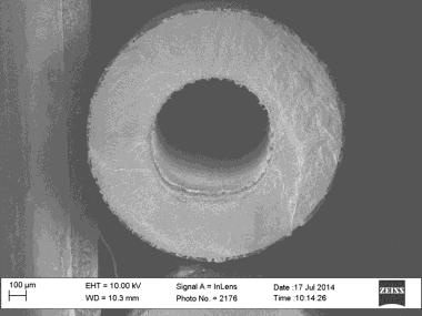
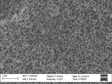
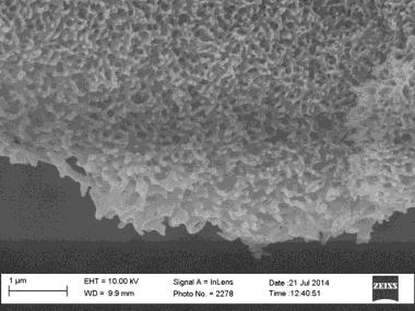
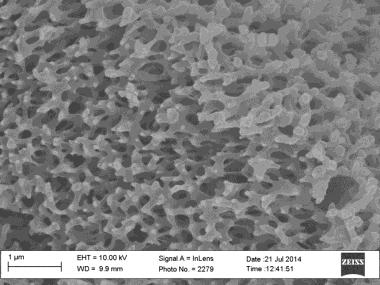
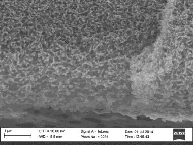

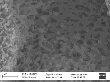
225 1. Bare Torlon Magnification 4kx 1 µm A D B E A D E F C B C F 15 Figure B.7 Cross-sectional outer layer pore sizes of bare Torlon fibers 199


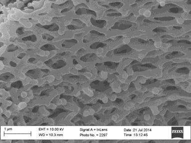
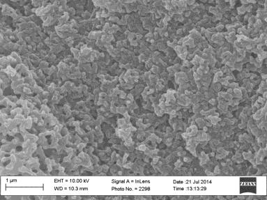
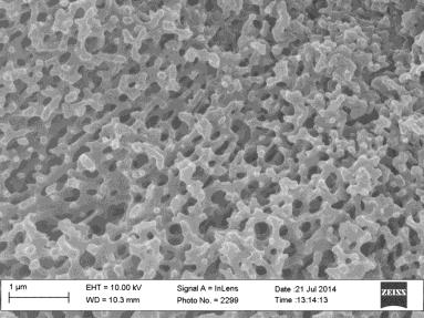
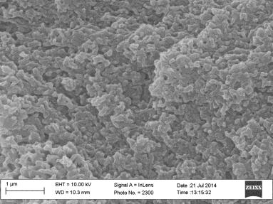

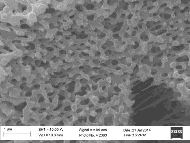
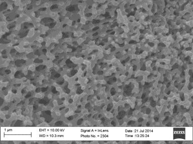
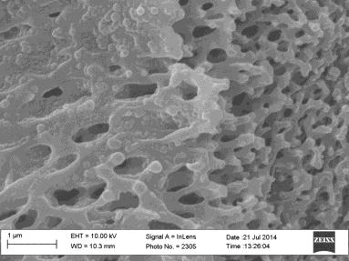
226 C D B A E G H F IPA only Magnification 4kx 1 µm A D Collapse G B Collapse E Collapse H C F Figure B.8 Cross-sectional outer layer pore sizes of PEI-PAI fibers that were solvent exchanged with IPA only. 200


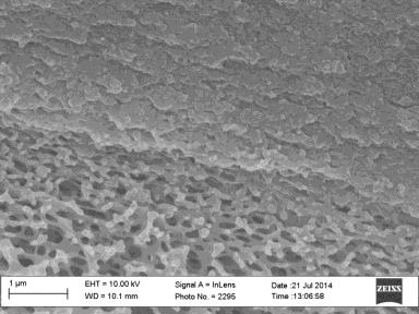
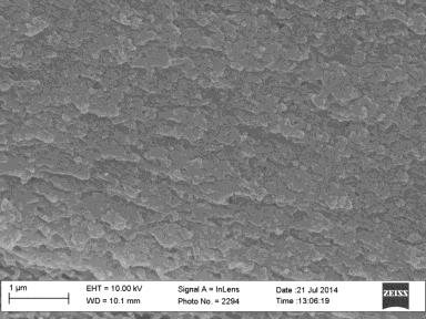
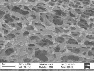
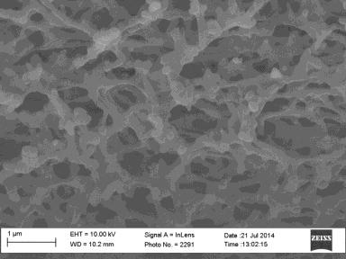
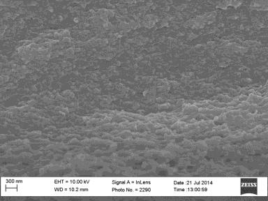
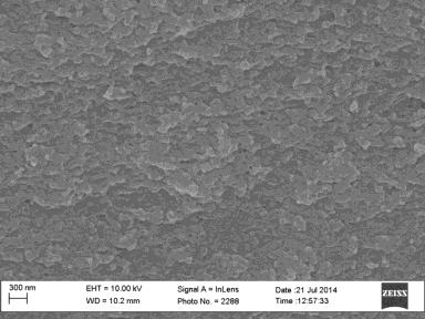
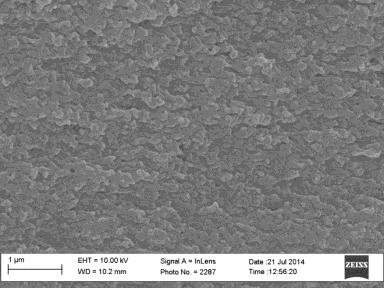
227 F E G B D A C IPA and Hexane A Collapse Magnification 4kx 1 µm D G B Collapse E C Collapse F Collapse Figure B.9 Cross-sectional outer layer pore sizes of PEI-PAI fibers that were solvent exchanged with IPA and hexane. 201
EXECUTIVE SUMMARY. especially in last 50 years. Industries, especially power industry, are the large anthropogenic
 EXECUTIVE SUMMARY Introduction The concentration of CO 2 in atmosphere has increased considerably in last 100 years, especially in last 50 years. Industries, especially power industry, are the large anthropogenic
Carbon dioxide removal processes by alkanolamines in aqueous organic solvents Hamborg, Espen Steinseth
 University of Groningen Carbon dioxide removal processes by alkanolamines in aqueous organic solvents Hamborg, Espen Steinseth IMPORTANT NOTE: You are advised to consult the publisher's version (publisher's
Technologies and Approaches of CO 2 Capture
 Southwest Regional Partnership Project Technologies and Approaches of CO 2 Capture Liangxiong Li, Brian McPherson, Robert Lee Petroleum Recovery Research Center New Mexico Institute of Mining and Technology,
Design and Synthesis of Nitrogen-Doped Porous Carbon Materials for CO 2 Capture and Investigation of CO 2 Sorption Kinetics
 Design and Synthesis of Nitrogen-Doped Porous Carbon Materials for CO 2 Capture and Investigation of CO 2 Sorption Kinetics Investigators Jennifer Wilcox, Assistant Professor, Energy Resources Engineering;
Adsorption Processes. Ali Ahmadpour Chemical Eng. Dept. Ferdowsi University of Mashhad
 Adsorption Processes Ali Ahmadpour Chemical Eng. Dept. Ferdowsi University of Mashhad Contents Introduction Principles of adsorption Types of adsorption Definitions Brief history Adsorption isotherms Mechanism
Novel Zeolite Adsorbents
 Research Development & Innovation Novel Zeolite Adsorbents for separation of Methane and Nitrogen for use in Swing Adsorption Systems UWA technology licensing/ partnering opportunity Processing of conventional
Kinetic enhancement of adsorbent for CO2 capture from atmosphere by porous material
 Engineering Conferences International ECI Digital Archives CO2 Summit II: Technologies and Opportunities Proceedings Spring 4-13-2016 Kinetic enhancement of adsorbent for CO2 capture from atmosphere by
Development of Technologies for Recovery and Removal of Fluorinated Compounds Causing Global Warming Abstract of the Report
 Global Environment Research Coordination System Development of Technologies for Recovery and Removal of Fluorinated Compounds Causing Global WarmingAbstract of the Report Contact person Shigeru Futamura
Laurea in Scienza dei Materiali Materiali Inorganici Funzionali. Carbon Capture and Storage CCS
 Laurea in Scienza dei Materiali Materiali Inorganici Funzionali Carbon Capture and Storage CCS Prof. Dr. Antonella Glisenti -- Dip. Scienze Chimiche -- Università degli Studi di di Padova Bibliography
3.2 Alkanes. Refining crude oil. N Goalby chemrevise.org 40 C 110 C 180 C. 250 C fuel oil 300 C 340 C. Fractional Distillation: Industrially
 3.2 Alkanes Refining crude oil Fractional Distillation: Industrially Petroleum is a mixture consisting mainly of alkane hydrocarbons Petroleum fraction: mixture of hydrocarbons with a similar chain length
SEPARATION BY BARRIER
 SEPARATION BY BARRIER SEPARATION BY BARRIER Phase 1 Feed Barrier Phase 2 Separation by barrier uses a barrier which restricts and/or enhances the movement of certain chemical species with respect to other
Complex Compounds Background of Complex Compound Technology
 Complex Compounds For more than 20 years, Rocky Research has been a pioneer in the field of sorption refrigeration utilizing complex compounds. Our technology earned special recognition from NASA in 1999.
Kinetic, Thermodynamic and Regeneration Studies for CO 2 Adsorption onto Activated Carbon
 International Journal of Advanced Mechanical Engineering. ISSN 50-334 Volume 4, Number 1 (014), pp. 7-3 Research India Publications http://www.ripublication.com/ijame.htm Kinetic, Thermodynamic and Regeneration
Technical Resource Package 1
 Technical Resource Package 1 Green Chemistry Impacts in Batch Chemical Processing UNIDO IAMC Toolkit Images may not be copied, transmitted or manipulated 1/5 The following list provides an overview of
Pressure Swing Adsorption: A Gas Separation & Purification Process
 Pressure Swing Adsorption: A Gas Separation & Purification Process Pressure swing adsorption is an adsorption-based process that has been used for various gas separation and purification purposes. Separation
A NEW SOLVENT FOR CO2 CAPTURE R.
 A NEW SOLVENT FOR CO 2 CAPTURE R. Viscardi, G. Vanga and V. Barbarossa vincenzo.barbarossa@enea.it C.R. Casaccia ENEA; via Anguillarese, 301; 00123 S. M. Galeria-Roma Abstract This experimental study describes
Adsorption of Methylene Blue on Mesoporous SBA 15 in Ethanol water Solution with Different Proportions
 2015 2 nd International Conference on Material Engineering and Application (ICMEA 2015) ISBN: 978-1-60595-323-6 Adsorption of Methylene Blue on Mesoporous SBA 15 in Ethanol water Solution with Different
Novel Ceramic Membrane for High Temperature Carbon Dioxide Separation
 Novel Ceramic Membrane for High Temperature Carbon Dioxide Separation Technical Progress Report (Semi-Annual) 09/01/01 02/28/02 Jun-ichi Ida Zhaohui Yang Jerry Y. S. Lin March 2002 DE-FG26-00NT40824 University
Figure 1. Pore size distribution
 Product Information '2:(;Ã237,325(Ã/ÃDQGÃ9 Polymeric Adsorbents Dow has developed a new polymeric adsorbent type for the concentration of organics from air and water. Key features of these adsorbents are:
Metal-Organic Frameworks and Porous Polymer Networks for Carbon Capture
 Carbon Capture Workshop, Tuesday, April 3 rd, Texas A&M, Qatar Metal-Organic Frameworks and Porous Polymer Networks for Carbon Capture J. P. Sculley, J.-R. Li, J. Park, W. Lu, and H.-C. Zhou Texas A&M
TRITIUM RECOVERY FROM WASTE USING A PALLADIUM MEMBRANE REACTOR
 TRITIUM RECOVERY FROM WASTE USING A PALLADIUM MEMBRANE REACTOR Stephen A. Birdsell and R. Scott Willms Los Alamos National Laboratory MS C348, Los Alamos, New Mexico 87545 ABSTRACT A large quantity of
Supporting Information
 Electronic Supplementary Material (ESI) for Energy & Environmental Science. This journal is The Royal Society of Chemistry 2018 Supporting Information One-of-A-Kind: A Microporous Metal-Organic Framework
Energy Tutorial: Carbon Capture 101
 GLOBAL CLIMATE AND ENERGY PROJECT STANFORD UNIVERSITY Energy Tutorial: Carbon Capture 101 GCEP RESEARCH SYMPOSIUM 2011 STANFORD, CA Professor Jennifer Wilcox Energy Resources Engineering Department Global
Available online at ScienceDirect. Energy Procedia 63 (2014 ) GHGT USA
 GHGT USA") Available online at www.sciencedirect.com ScienceDirect Energy Procedia 63 (2014 ) 1487 1496 GHGT-12 CO 2 mass transfer and solubility in aqueous primary and secondary amine Le Li a, Gary Rochelle a, *
Available online at www.sciencedirect.com ScienceDirect Energy Procedia 63 (2014 ) 1487 1496 GHGT-12 CO 2 mass transfer and solubility in aqueous primary and secondary amine Le Li a, Gary Rochelle a, *
GREEN ENGINEERING PRINCIPLE
 GREEN ENGINEERING INNOVATIVE ION EXCHANGE TECHNOLOGY FOR TREATMENT OF AQUEOUS EFFLUENT STREAMS & DEVELOPING GREENER PROCESSES THROUGH RECOVERY & REUSE OF VALUABLE PRODUCTS. C. NANDI NOCIL LTD. GREEN ENGINEERING
Adsorption (Ch 12) - mass transfer to an interface
 - mass transfer to an interface") Adsorption (Ch 12) - mass transfer to an interface (Absorption - mass transfer to another phase) Gas or liquid adsorption (molecular) onto solid surface Porous solids provide high surface area per weight
Adsorption (Ch 12) - mass transfer to an interface (Absorption - mass transfer to another phase) Gas or liquid adsorption (molecular) onto solid surface Porous solids provide high surface area per weight
LATEST TECHNOLOGY IN Safe handling & Recovery OF Solvents in Pharma Industry
 LATEST TECHNOLOGY IN Safe handling & Recovery OF Solvents in Pharma Industry TYPICAL SOLVENT USE IN Pharma Industry Usage of solvents in an API process development is for: Diluent to carry out reaction
Synthesis and Characterization of high-performance ceramic materials for hightemperature
 Synthesis and Characterization of high-performance ceramic materials for hightemperature CO 2 capture and hydrogen production. Location: Institute for Energy Technology (IFE), Kjeller, Norway Department
UPGRADING OF PETROLEUM RESIDUE BY NITROGEN DOPING FOR CO 2 ADSORPTION
 UPGRADING OF PETROLEUM RESIDUE BY NITROGEN DOPING FOR CO 2 ADSORPTION Nattha Chalermwat a,b, Thanyalak Chaisuwan a,b, Uthaiporn Suriyapraphadilok*,a,b a The Petroleum and Petrochemical College, Chulalongkorn
ADSORPTION AND DESORPTION OF CO ON SOLID SORBENTS
 ADSORPTION AND DESORPTION OF CO ON SOLID SORBENTS Ranjani Siriwardane (rsiiw@netl.doe.gov; 34-85-4513) Ming Shen (mshen@netl.doe.gov; 34-85-411) Edward Fisher (efishe@netl.doe.gov; 34-85-411) James Poston
Porous systems for high performance CO 2 capture: The MATESA selective CO 2 capture materials
 Porous systems for high performance CO 2 capture: The MATESA selective CO 2 capture materials Alessio Masala Ph.D. student Prof. Silvia Bordiga Supervisor MATESA Dissemination Day, Jun. 16 th, 2016, OSLO,
General Separation Techniques
 ecture 2. Basic Separation Concepts (1) [Ch. 1] General Separation Techniques - Separation by phase creation - Separation by phase addition - Separation by barrier - Separation by solid agent - Separation
Experimental study into carbon dioxide solubility and species distribution in aqueous alkanolamine solutions
 Air Pollution XX 515 Experimental study into carbon dioxide solubility and species distribution in aqueous alkanolamine solutions H. Yamada, T. Higashii, F. A. Chowdhury, K. Goto S. Kazama Research Institute
Advancing Adsorption and Membrane-Separation Processes for the Gigaton Carbon Capture Challenge
 I CH05CH22-Wilcox ARI 24 March 2014 17:58 R E V I E W S E Review in Advance first posted online on April 3, 2014. (Changes may still occur before final publication online and in print.) N C A D V A N Annu.
CO 2 capture by Adsorption Processes: From Materials to Process Development to Practical Implementation
 CO 2 capture by Adsorption Processes: From Materials to Process Development to Practical Implementation Paul A. Webley Dept. of Chemical Engineering Talloires, July 2010 Outline Adsorption for Post-Combustion
Atmospheric Analysis Gases. Sampling and analysis of gaseous compounds
 Atmospheric Analysis Gases Sampling and analysis of gaseous compounds Introduction - External environment (ambient air) ; global warming, acid rain, introduction of pollutants, etc - Internal environment
MATHEMATICAL MODELING OF DISBONDED COATING AND CATHODIC DELAMINATION SYSTEMS KERRY N. ALLAHAR
 MATHEMATICAL MODELING OF DISBONDED COATING AND CATHODIC DELAMINATION SYSTEMS By KERRY N. ALLAHAR A DISSERTATION PRESENTED TO THE GRADUATE SCHOOL OF THE UNIVERSITY OF FLORIDA IN PARTIAL FULFILLMENT OF THE
Supercritical Fluid Extraction Directly Coupled with Reversed Phase Liquid Chromatography for Quantitative Analysis of Analytes in Complex Matrices
 Supercritical Fluid Extraction Directly Coupled with Reversed Phase Liquid Chromatography for Quantitative Analysis of Analytes in Complex Matrices by Zhenyu Wang Dissertation submitted to the Graduate
Physicochemical Processes
 Lecture 3 Physicochemical Processes Physicochemical Processes Air stripping Carbon adsorption Steam stripping Chemical oxidation Supercritical fluids Membrane processes 1 1. Air Stripping A mass transfer
IN SITU 13 C NMR TO DEVELOP MATERIALS FOR THE CAPTURE AND SEQUESTRATION OF CO 2
 IN SITU 13 C NMR TO DEVELOP MATERIALS FOR THE CAPTURE AND SEQUESTRATION OF CO 2 Sophia Hayes, Mark Conradi, Phil Skemer Washington University in St. Louis Carbon Sequestration Sequestration conditions:
m WILEY- ADSORBENTS: FUNDAMENTALS AND APPLICATIONS Ralph T. Yang Dwight F. Benton Professor of Chemical Engineering University of Michigan
 ADSORBENTS: FUNDAMENTALS AND APPLICATIONS Ralph T. Yang Dwight F. Benton Professor of Chemical Engineering University of Michigan m WILEY- INTERSCIENCE A JOHN WILEY & SONS, INC., PUBLICATION Preface xi
Apportioning of Fuel and Thermal NO x
 DEVELOPMENT OF STABLE NITROGEN ISOTOPE RATIO MEASUREMENTS OBJECTIVES The main aim of the project was to develop a nitrogen-stable isotope measurement technique for NO x and to ascertain whether it can
DMOF-1 as a Representative MOF for SO 2 Adsorption in both Humid and Dry Conditions
 DMOF-1 as a Representative MOF for SO 2 Adsorption in both Humid and Dry Conditions Julian Hungerford, Souryadeep Bhattacharyya, Uma Tumuluri, Sankar Nair, Zili Wu, and Krista S. Walton* School of Chemical
R&D on adsorption processing technology using pitch activated carbon fiber
 1999D.4.1.1 R&D on adsorption processing technology using pitch activated carbon fiber 1. Contents of empirical research With respect to waste water, exhausts and other emissions in the petroleum refining
Lecture 7. Sorption-Separation Equipment
 Lecture 7. Sorption-Separation Equipment Adsorption - Stirred-tank, slurry operation - Cyclic fixed-bed batch operation - Thermal (temperature)-swing adsorption - Fluidizing bed for adsorption and moving
Development of reactive chemical absorbents at the CSIRO
 Development of reactive chemical absorbents at the CSIRO HiPerCap Workshop, March 25 2015 Graeme Puxty Research Team Leader CSIRO ENERGY FLAGSHIP CSIRO s chemical absorbent research program Concept Kinetics,
AN OVERVIEW OF NUCLEAR ENERGY. Prof. Mushtaq Ahmad, MS, PhD, MIT, USA
 AN OVERVIEW OF NUCLEAR ENERGY Prof. Mushtaq Ahmad, MS, PhD, MIT, USA Outline of the Seminar 2 Motivation and Importance of Nuclear Energy Future Energy Planning in the Kingdom Current Status of Nuclear
Monitoring Emulsion Polymerization by Raman Spectroscopy
 An Executive Summary Monitoring Emulsion Polymerization by Raman Spectroscopy Why process analytical matters to process development R&D. Serena Stephenson, PhD Senior R&D Analytical Manager Kishori Deshpande,
Biomimetic Sorbents for Selective CO2 Capture Investigators Abstract Introduction
 Biomimetic Sorbents for Selective CO2 Capture Investigators Jennifer Wilcox, Assistant Professor, Energy Resources Engineering; T. Daniel P. Stack, Associate Professor, Chemistry; Zhenan Bao, Associate
Porous Solids for Biogas Upgrading
 WASTES: Solutions, Treatments and Opportunities 2 nd International Conference September 11 th 13 th 2013 Porous Solids for Biogas Upgrading J.A.C. Silva 1 and A.E. Rodrigues 2 1 Escola Superior de Tecnologia
Lecture 10. Membrane Separation Materials and Modules
 ecture 10. Membrane Separation Materials and Modules Membrane Separation Types of Membrane Membrane Separation Operations - Microporous membrane - Dense membrane Membrane Materials Asymmetric Polymer Membrane
Viscosity data of aqueous MDEA [Bmim][BF 4 ] solutions within carbon capture operating conditions
![Viscosity data of aqueous MDEA [Bmim][BF 4 ] solutions within carbon capture operating conditions](/thumbs/81/84724087.jpg "Viscosity data of aqueous MDEA [Bmim][BF 4 ] solutions within carbon capture operating conditions") Available online at www.sciencedirect.com Energy Procedia 00 (2016) 000 000 www.elsevier.com/locate/procedia The 8 th International Conference on Applied Energy ICAE2016 Viscosity data of aqueous MDEA
Available online at www.sciencedirect.com Energy Procedia 00 (2016) 000 000 www.elsevier.com/locate/procedia The 8 th International Conference on Applied Energy ICAE2016 Viscosity data of aqueous MDEA
DEPARTMENT OF CHEMICAL ENGINEERING University of Engineering & Technology, Lahore. Mass Transfer Lab
 DEPARTMENT OF CHEMICAL ENGINEERING University of Engineering & Technology, Lahore Mass Transfer Lab Introduction Separation equipments account for a major part of the capital investment in process industry.
OMICS Group International is an amalgamation of Open Access publications
 About OMICS Group OMICS Group International is an amalgamation of Open Access publications and worldwide international science conferences and events. Established in the year 2007 with the sole aim of
Pre-seeding -assisted synthesis of high performance polyamide-zeolite nanocomposie membrane for water purification
 Electronic Supporting Information: Pre-seeding -assisted synthesis of high performance polyamide-zeolite nanocomposie membrane for water purification Chunlong Kong, a Takuji Shintani b and Toshinori Tsuru*
INDUSTRIAL EXPERIENCE WITH HYBRID DISTILLATION PERVAPORATION OR VAPOR PERMEATION APPLICATIONS
 INDUSTRIAL EXPERIENCE WITH HYBRID DISTILLATION PERVAPORATION OR VAPOR PERMEATION APPLICATIONS Mario Roza, Eva Maus Sulzer Chemtech AG, Winterthur, Switzerland; E-mails: mario.roza@sulzer.com, eva.maus@sulzer.com
PREFACE. Julian C. Smith Peter Harriott. xvii
 PREFACE This sixth edition of the text on the unit operations of chemical engineering has been extensively revised and updated, with much new material and considerable condensation of some sections. Its
Zeolites: Absorbents, Adsorbents. Prepared for the. Congress April 6 th 9 th, 2003 Montreal, Quebec. LuVerne E.W. Hogg
 Zeolites: Absorbents, Adsorbents Prepared for the 16 th Industrial Minerals International Congress April 6 th 9 th, 2003 Montreal, Quebec By LuVerne E.W. Hogg C2C Zeolite Corporation Our Mission: To utilize
Surface modification of Microfibrillated Cellulose films by Gas-Phase Esterification: Improvement of Barrier Properties.
 Surface modification of Microfibrillated Cellulose films by Gas-Phase Esterification: Improvement of Barrier Properties. G. Rodionova*, M. Lenes**, Ø. Eriksen**, B. H. Hoff*, Ø. W. Gregersen* * Norwegian
Module: 7. Lecture: 36
 Module: 7 Lecture: 36 DIMETHYL FORMAMIDE INTRODUCTION Dimethylformamide is an organic compound and denotes as DMF. The name is derived from the fact that it is a derivative of formamide, the amide of formic
Current status of R&D in post combustion CO 2 capture
 Current status of R&D in post combustion CO 2 capture Kaj Thomsen, Ph.D. Center for Energy Resources Engineering, CERE DTU Chemical Engineering Technical University of Denmark Outline Choice of solvent
Studies of N,N-Dibutyltrimethylenediamine and N, N, N Triethylenediamine for CO 2
 Pertanika J. Sci. & Technol. 16 (1): 61-71 (2008) ISSN: 0128-7680 Universiti Putra Malaysia Press Studies of N,N-Dibutyltrimethylenediamine and N, N, N Triethylenediamine for CO 2 Absorption and Desorption
HYDROGEN PRODUCTION THROUGH SORPTION ENHANCED REFORMING
 HYDROGEN PRODUCTION THROUGH SORPTION ENHANCED REFORMING H.T.J. Reijers, D.F. Roskam-Bakker, J.W. Dijkstra, R.P. de Smidt, A. de Groot, R.W. van den Brink Address: Energy research Centre of the Netherlands,
Opportunities for Geothermal Development Created by New Technologies S2-1-2
 Opportunities for Geothermal Development Created by New Technologies S2-1-2 Geothermal Academy Masami Nakagawa Director of Geothermal Academy Fulbright Energy Specialist CSM/NREL Joint Appointee Department
This is a repository copy of Optimised PEI impregnation of activated carbons - Enhancement of CO2 capture under post-combustion conditions.
 This is a repository copy of Optimised PEI impregnation of activated carbons - Enhancement of CO2 capture under post-combustion conditions. White Rose Research Online URL for this paper: http://eprints.whiterose.ac.uk/89498/
Simulation of gas sweetening process using new formulated amine solutions by developed package and HYSYS
 Simulation of gas sweetening process using new formulated amine solutions by developed package and Mohammad Irani 1 ١, Reza Dorosti 2, Akbar Zamaniyan 1, Marziye Zare 1- Research Institute of Petroleum
Mengying Li.
 Investigating the Techniques of Acid- Base Extraction by separating three dye compounds & Recrystallization by purifying Methyl Orange Mengying Li Department of Chemical Engineering, The Pennsylvania State
SCR Catalyst Deactivation for PRB-Firing Coal Utility Boilers
 SCR Catalyst Deactivation for PRB-Firing Coal Utility Boilers Christopher Bertole Cormetech, Inc. Presentation Outline Cormetech Experience Catalyst Deactivation from Ca, P, and Na Impact on Catalyst Activity
Diffusion and Adsorption in porous media. Ali Ahmadpour Chemical Eng. Dept. Ferdowsi University of Mashhad
 Diffusion and Adsorption in porous media Ali Ahmadpour Chemical Eng. Dept. Ferdowsi University of Mashhad Contents Introduction Devices used to Measure Diffusion in Porous Solids Modes of transport in
Alain Dufresne. Nanocellulose. From Nature to High Performance Tailored Materials OE GRUYTER
 Alain Dufresne Nanocellulose From Nature to High Performance Tailored Materials OE GRUYTER Contents Preface - vii 1 Cellulose and potential reinforcement-1 1.1 Polysaccharides-1 1.2 Chemical structure
Essential Knowledge. 2.A.3 Organisms must exchange matter with the environment to grow, reproduce and maintain organization
 Ch3: Water Essential Knowledge 2.A.3 Organisms must exchange matter with the environment to grow, reproduce and maintain organization a. Molecules and atoms from the environment are necessary to build
ADVANCES IN OLEFIN PURIFICATION VIA CATALYSIS AND SORBENT MATERIALS
 THE CATALYST GROUP RESOURCES ADVANCES IN OLEFIN PURIFICATION VIA CATALYSIS AND SORBENT MATERIALS A technical investigation commissioned by the members of the Catalytic Advances Program (CAP) Client Private
Recap: Introduction 12/1/2015. EVE 402 Air Pollution Generation and Control. Adsorption
 EVE 402 Air Pollution Generation and Control Chapter #6 Lectures Adsorption Recap: Solubility: the extent of absorption into the bulk liquid after the gas has diffused through the interface An internal
INTRODUCTION TO CATALYTIC COMBUSTION
 INTRODUCTION TO CATALYTIC COMBUSTION R.E. Hayes Professor of Chemical Engineering Department of Chemical and Materials Engineering University of Alberta, Canada and S.T. Kolaczkowski Professor of Chemical
Edexcel Chemistry Checklist
 Topic 1. Key concepts in chemistry Video: Developing the atomic model Describe how and why the atomic model has changed over time. Describe the difference between the plum-pudding model of the atom and
Module: 7. Lecture: 36
 Module: 7 Lecture: 36 DIMETHYL FORMAMIDE INTRODUCTION Dimethylformamide is an organic compound and denotes as DMF. The name is derived from the fact that it is a derivative of formamide, the amide of formic
Efficient Separations Technologies for Petroleum Refining. R. Bruce Eldridge Process Science and Technology Center The University of Texas
 Efficient Separations Technologies for Petroleum Refining R. Bruce Eldridge Process Science and Technology Center The University of Texas PROCESS SCIENCE &TECHNOLOGY CENTER UT - Austin Texas A&M PROCESS
INDUCTIVELY COUPLED PLASMA MASS SPECTROMETRY
 INDUCTIVELY COUPLED PLASMA MASS SPECTROMETRY Edited by AKBAR MONTASER George Washington University Washington, D.C. 20052, USA WILEY-VCH New York Chichester Weinheim Brisbane Singapore Toronto CONTENTS
Method and process for combustion synthesized supported cobalt catalysts for fixed bed Fischer Tropsch reaction
 Method and process for combustion synthesized supported cobalt catalysts for fixed bed Fischer Tropsch reaction Center for Sustainable Technologies Indian Institute of Science Bangalore IDF presentation
2. (i) Infrared (radiation absorbed) by (C H) bond vibration ALLOW bond stretching OR bond bending DO NOT ALLOW molecules vibrating 2
 Infrared (radiation absorbed) by (C H) bond vibration ALLOW bond stretching OR bond bending DO NOT ALLOW molecules vibrating 2") . (i) Species with an unpaired electron ALLOW atom, molecule or particle with an unpaired electron ALLOW has an unpaired electron ALLOW particle formed by homolytic fission DO NOT ALLOW particle with a
. (i) Species with an unpaired electron ALLOW atom, molecule or particle with an unpaired electron ALLOW has an unpaired electron ALLOW particle formed by homolytic fission DO NOT ALLOW particle with a
Exercise 9 - Petrochemicals and Climate
 113 Exercise 9 - Petrochemicals and Climate 1. The year of the first U.S. drilled oil well. c. 1859 2. Approximately, what percent of the world's remaining oil reserves are in the United States? a. 2%
The application of nano aluminum powder on solid propellant
 The application of nano aluminum powder on solid propellant Metal incendiary agent is one of the important components of modern solid propellant, which can improve the explosion heat and density of propellant.
Processes and Process Variables
 FACULTY OF PETROLEUM & RENEWABLE ENERGY ENGINEERING Course Learning Outcomes Chapter 2 Processes and Process Variables At the end of this course students will be able to Calculate the composition in term
Combustion Theory and Applications in CFD
 Combustion Theory and Applications in CFD Princeton Combustion Summer School 2018 Prof. Dr.-Ing. Heinz Pitsch Copyright 201 8 by Heinz Pitsch. This material is not to be sold, reproduced or distributed
International Journal of Scientific Research and Modern Education (IJSRME) ISSN (Online): (www.rdmodernresearch.com) Volume I, Issue I,
 ISSN (Online): (www.rdmodernresearch.com) Volume I, Issue I,") OXYGEN CONCENTRATORS A STUDY Mohammed Salique*, Nabila Rumane**, RohanBholla***, Siddharth Bhawnani**** & Anita Kumari***** Chemical Engineering Department, Thadomal Shahani Engineering College, Off Linking
OXYGEN CONCENTRATORS A STUDY Mohammed Salique*, Nabila Rumane**, RohanBholla***, Siddharth Bhawnani**** & Anita Kumari***** Chemical Engineering Department, Thadomal Shahani Engineering College, Off Linking
Amine-impregnated silica monolith with a hierarchical pore structure: enhancement of CO 2 capture capacity
 1 Electronic Supplementary Information (ESI) Amine-impregnated silica monolith with a hierarchical pore structure: enhancement of CO 2 capture capacity for Chao Chen, Seung-Tae Yang, Wha-Seung Ahn* and
-:Vijay Singh(09CEB023)
") Heterogeneous Semiconductor Photocatalyst -:Vijay Singh(09CEB023) Guided by Azrina Abd Aziz Under Dr. Saravanan Pichiah Preparation of TiO 2 Nanoparticle TiO 2 was prepared by hydrolysis and poly-condensation
Heterogeneous Semiconductor Photocatalyst -:Vijay Singh(09CEB023) Guided by Azrina Abd Aziz Under Dr. Saravanan Pichiah Preparation of TiO 2 Nanoparticle TiO 2 was prepared by hydrolysis and poly-condensation
Sampling. Information is helpful in implementing control measures for reducing pollutant concentration to acceptable levels
 Types of pollutant sampling and measurement: Air quality monitoring: Sampling and measurement of air pollutants generally known, as air quality monitoring. It is an integral component of any air pollution
An Introduction to Chemical Kinetics
 An Introduction to Chemical Kinetics Michel Soustelle WWILEY Table of Contents Preface xvii PART 1. BASIC CONCEPTS OF CHEMICAL KINETICS 1 Chapter 1. Chemical Reaction and Kinetic Quantities 3 1.1. The
Synthesis of Zeolite Composite Membranes for CO2 Separation
 Synthesis of Zeolite Composite Membranes for CO2 Separation April. 10. 2003 Sang Hoon Hyun, Dong Wook Shin, Young Eun Lee, Moon Hee Han*, and Churl Hee Cho* School of Materials Science & Engineering Yonsei
AQA Chemistry Checklist
 Topic 1. Atomic structure Video: Atoms, elements, compounds, mixtures Use the names and symbols of the first 20 elements in the periodic table, the elements in Groups 1 and 7, and other elements in this
GHGT-11. A Moisture Swing Sorbent for Direct Air Capture of Carbon Dioxide: Thermodynamic and kinetic. analysis
 Available online at www.sciencedirect.com Energy Procedia 37 (2013 ) 6096 6104 GHGT-11 A Moisture Swing Sorbent for Direct Air Capture of Carbon Dioxide: Thermodynamic and kinetic analysis Tao Wang a,b,
Methods of pollution control and waste management - laboratory. Adsorptive removal of volatile organic compounds from gases streams
 Methods of pollution control and waste management - laboratory Adsorptive removal of volatile organic compounds from gases streams Manual for experiment 17 dr Hanna Wilczura-Wachnik and dr inż. Jadwiga
c 2011 JOSHUA DAVID JOHNSTON ALL RIGHTS RESERVED
 c 211 JOSHUA DAVID JOHNSTON ALL RIGHTS RESERVED ANALYTICALLY AND NUMERICALLY MODELING RESERVOIR-EXTENDED POROUS SLIDER AND JOURNAL BEARINGS INCORPORATING CAVITATION EFFECTS A Dissertation Presented to
Measurement techniques
 Measurement techniques 1 GPC GPC = gel permeation chromatography GPC a type of size exclusion chromatography (SEC), that separates analytes on the basis of size. The column used for GPC is filled with
Dynamic cyclic performance of phenol-formaldehyde resinderived carbons for pre-combustion CO 2 capture: An experimental study
 Available online at www.sciencedirect.com Energy Procedia 37 (213 ) 127 133 GHGT-11 Dynamic cyclic performance of phenol-formaldehyde resinderived carbons for pre-combustion CO 2 capture: An experimental
STUDY ON THE IMPROVEMENT OF THE REDUCTION CAPACITY OF ACTIVATED CARBON FIBER
 STUDY ON THE IMPROVEMENT OF THE REDUCTION CAPACITY OF ACTIVATED CARBON FIBER Chen Shuixia, Zeng Hanmin Materials Science Institute, Zhongshan University, Guangzhou 51275, China Key Laboratory for Polymeric
DISPLAY YOUR STUDENT ID CARD ON THE TOP OF YOUR DESK NOW UNIVERSITY OF VICTORIA. CHEMISTRY 102 Midterm Test 1 February 1, pm (60 minutes)
") SECTION: (circle one): A01 MR (Dr. Lipson) A02 (Dr. Briggs) A03 MWR (Dr. Brolo) NAME Student No. V0 (Please print clearly.) DISPLAY YOUR STUDENT ID CARD ON THE TOP OF YOUR DESK NOW Version A UNIVERSITY
SECTION: (circle one): A01 MR (Dr. Lipson) A02 (Dr. Briggs) A03 MWR (Dr. Brolo) NAME Student No. V0 (Please print clearly.) DISPLAY YOUR STUDENT ID CARD ON THE TOP OF YOUR DESK NOW Version A UNIVERSITY
Dendritic Star Polymer of Polyacrylamide Based on β-cyclodextrin Trimer: A. Flocculant and Drug Vehicle
 Electronic Supplementary Material (ESI) for New Journal of Chemistry. This journal is The Royal Society of Chemistry and the Centre National de la Recherche Scientifique 2016 Electronic Supporting Information
Polyethyleneimine Loading into High Internal Phase Emulsion Polymer for CO 2 Adsorption: Synthesis and Characterization of the PolyHIPE
 A publication of CHEMICAL ENGINEERING TRANSACTIONS VOL. 29, 2012 Guest Editors: Petar Sabev Varbanov, Hon Loong Lam, Jiří Jaromír Klemeš Copyright 2012, AIDIC Servizi S.r.l., ISBN 978-88-95608-20-4; ISSN