Understanding the Effect of Cationic Substitution on Redox Potential in Layered Compounds
|
|
|
- Stella Imogene Wilkinson
- 6 years ago
- Views:
Transcription
1 Chapter 5 Understanding the Effect of Cationic Substitution on Redox Potential in Layered Compounds CHAPTER 5 UNDERSTANDING THE EFFECT OF CATIONIC SUBSTITUTION ON REDOX POTENTIAL IN LAYERED COMPOUNDS As mentioned in the previous chapter, Ni2+/Ni3+/Ni4+ redox potentials can be tuned with different cationic substitution in LiNi1/3TM11/3TM21/3O2 or LiNi1/2TM21/2O2 systems, where TM1 is a 3+ transition metal (Co3+, Al3+, Fe3+ etc.) and TM2 is a 4+ transition metal (Ti4+, Zr4+, Mn4+ etc.). In this chapter, the changes and trends in the nickel redox potentials are systematically compared and summarized. The electronic structure of those materials is studied in details in the attempt to understand these changes and trends. With a brief review of the literature on voltage tuning associated with lithium intercalation compounds; we adopt the concept of the inductive effect to describe in-depth understanding of ab initio calculated voltages in layered materials. 5.1 Ni Redox Potential in Different Compounds Voltages of LiNi1/3TM11/3TM21/3O2 or LiNi1/2TM21/2O2 systems are calculated according to equation 5-1[1]. V ( x) where anode Li ( cathode Li anode Li ) Eq. 5-1 ze constant if metallic lithium is used as anode; cathode Li ( Gf x ) T,P, N host 103
2 Chapter 5 Understanding the Effect of Cationic Substitution on Redox Potential in Layered Compounds In the thesis, Gf is approximated by E (total energy) because electronic and vibrational excitations are not considered. In these layered compounds it is possible to identify which redox couple is active in the particular voltage ranges, by examining the projected density of states on different cations, as tabulated in Table 5-I. Table 5-I GGA calculated voltages of LiNi1/3TM11/3TM21/3O2 or LiNi1/2TM21/2O2 systems Composition Ni2+/Ni3+ Ni2+/Ni3+ Ave. Other Redox Pair Voltage LiNi1/2Mn1/2O2 2.94V 3.51V 3.22V LiNi1/2Ti1/2O2 3.13V 3.87V 3.50V LiNi1/2Zr1/2O2 2.96V 3.85V 3.41V LiNi1/2Mo1/2O2 Inactive N.A. Mo4+/Mo6+(2.91) LiNi1/3Co1/3Mn1/3O2 2.82V 3.17V 3.00V Co3+/Co4+(4.20) LiNi1/3Fe1/3Mn1/3O2 2.95V 3.20~3.80V 3.08V* Fe3+/Fe4+(3.20~3.80) LiNi1/3Al1/3Mn1/3O2 3.29V 3.33V 3.31V Al3+/Al4+(5.05) LiNi1/3Co1/3Ti1/3O2 2.98V 3.32V 3.15V Co3+/Co4+(4.33) LiNi1/3Co1/3Zr1/3O2 2.88V 3.45V 3.16V Co3+/Co4+(4.28) *Due to simultaneous redox reactions of Ni3+/Ni4+ and Fe3+/Fe4+, the average voltage is calculated using a mid-point volatage 3.20V for Ni3+/Ni4+ couple. If the voltages at which the Ni2+/Ni3+/Ni4+ couples are active in LiNi1/2Mn1/2O2 are taken as the reference point, in LiNi1/2TM21/2O2 and LiNi1/3TM11/3TM21/3O2, Fe and Co doping lowers the voltages, while all other cation substitutions increase the delithiation voltages. 104
3 Chapter Understanding the Effect of Cationic Substitution on Redox Potential in Layered Compounds Computational Details In order to find out how and why nickel redox potential are changed when substituted with different cations, we first look at the atomic arrangements of the supercells in the ab initio computations as shown in Figure 5-1. As mentioned before, the close packed oxygen planes have an ABCABC stacked oxygen frame. The stacking sequence of ordered transition metal planes is a1b in all calculations of this work. For consistency, the LiNi1/2TM21/2O2 system has the zig-zag ordering, and the LiNi1/3TM11/3TM21/3O2 has such ordering so that each Ni2+ ion has three 3+ and three 4+ ions as the nearest neighbor. Supercells of four formula units and three formula units are used in the two systems respectively. Ni2+ TM3+ TM4+ Figure 5-1 Ni, TM13+, TM24+ ordering in the supercells of Li(Ni1/3TM11/3TM21/3)O2 and Li(Ni1/2TM21/2)O2 5.3 Electronic Structure of Transition Metal Ion To understand the reasons why the nickel redox potential can be tuned with cationic substitution, we have to exam the electronic structure of the nickel in the layered lithium transition metal oxides. In the layered crystal structure, the transition metal is octahedrally coordinated with oxygen. Electron p orbitals of oxygen overlap with s, p and d orbitals from the transition metal, forming bonding and anti-bonding 105

4 Chapter 5 Understanding the Effect of Cationic Substitution on Redox Potential in Layered Compounds levels. The oxygen p bands are filled and the transition metal d bands are empty or partially occupied. Crystal field theory [2-4] demonstrates that the interaction of the d orbitals with the electrostatic potential due to the negatively charged oxygen ions of the octahedron produces an increase in the energy of the eg orbitals with respect to the energy of the t2g orbitals. This happens because the eg orbitals have lobes pointing toward the oxygen ions while the lobes of the t2g orbitals point between oxygen ions. More accurately, the covalent mixing that exists between the transition metal ion and the oxygen ions affects their interaction. The eg orbitals directly overlap with the p orbitals of oxygen forming bonding and antibonding levels, referred as egb and eg*, as indicated in Figure 5-2. The separation between the bonding and anti-bonding levels becomes more pronounced as the difference in the energy of the metal d levels and the oxygen p levels widens. eg * T.M. Li t2g 3d 2p eg Metal b Oxygen Figure 5-2 Schematic illustration of the bonding and anti-bonding levels that arise for a transition metal ion octahedrally coordinated by oxygen ions. The splitting is due to the hybridization between the valence electronic states of the transition metal ion with those of the oxygen ions. The stronger is the cation-anion covalent bonding, the higher is the anti-bonding level. If the redox process consists of exchanging an electron with these levels (as in 106
5 Chapter 5 Understanding the Effect of Cationic Substitution on Redox Potential in Layered Compounds the case of Ni2+/Ni4+) then a higher energy will give a lower extraction voltage. This covalent bonding may be modulated by the strength of the covalent bonding of the anion with another neighboring cation without changing the primary structure. Modulation of the strength of the cation-anion covalence at a given cation by nearest-neighbor cations that compete for the same anion valence electrons is know as the inductive effect [5]. 5.4 Tuning the Voltage by the Inductive Effect Variation in voltages at which a given cation redox couple is active depends on two factors: (a) the magnitude of the crystalline electric field at the cation; and (b) the covalent contribution to the bonding, that may be modulated by the strength of the covalent bonding at the nearest-neighbor cations. The former may be estimated for a purely ionic model by a Madelung summation of the Coulomb fields from the other ions present; changes of structure alter primarily the Madelung energy. The stronger is the negative Madelung potential at a cation, the higher energy is a given redox couple; and the stronger is the covalent bonding of the electrons at a transition metal cation, the higher is the redox energy of that cation ion. [5] It should be noted that raising the energy of a given redox couple in a cathode lowers the voltage. In this study, we do not consider the Madelung energy since the structure of the compounds studied is always O3 type layered structure. In NASICON materials, it has been illustrated that the Fe3+/Fe2+ redox potential can be tuned by anionic substitution [6, 7]. In Fe2(SO4)3, LiFe2(SO4)2(PO4) and Li3Fe2(PO4)3, the redox voltages of Fe3+/Fe2+ are 3.6V, 3.4V and 2.8V respectively because the Fe PO4 bonding is more covalent than the Fe SO4 bonding. 107
6 Chapter 5 Understanding the Effect of Cationic Substitution on Redox Potential in Layered Compounds Similarly, we will also expect that changing of the counter cation in the Li(Ni,TM1,TM2)O2 systems alters primarily the inductive effect, thus changes the Ni redox potential. Table 5-II shows the calculated redox potential of various metal cation in the O3 layered LiTMO2 structure. Tabel 5-II Redox potential of transition metal cation in the O3 layered structure LiTMO2 M in LiMO2 Av. Voltage (V) for MO2/LiMO2 Ti V Cr Mn Fe Co Ni Cu Mo a b c All values obtained from reference [8], except a. Notice the ground state for LiFeO2 is not a layered structure b. Calculated as 3.17V in Ref [8], the difference is due to different pseudo potential used in calculation c. Calculated in this work If charge transfer occurs mainly on the transition metal valence electron when Li is de-intercalated, the more amount of orbital mixing (covalent the bonding character) is, the higher is the redox couple M3+/M4+ energy, thus the lower is the voltage. For example, in LiNi1/2Mn1/2O2, the redox potential of Ni2+/Ni3+ and Ni3+/Ni4+ are calculated as 2.94V and 3.51V, respectively [9]. While in LiNi1/2Ti1/2O2, these values increase to 3.13V and 3.87V. Ti and Mn has very similar electronegativity (see Table 5-3), but Ti4+ is bigger in size and has no d electrons available, therefore there will be substantial amount of orbital mixing of Ti-O bonding than the Mn-O bonding in the structure. Substitution of Mn by Ti induces a reduction in the hybridization between the Ni d-levels and the oxygen p-levels, therefore decreases 108
7 Chapter 5 Understanding the Effect of Cationic Substitution on Redox Potential in Layered Compounds the covalency of Ni-O bonding, and lowers the Ni redox energy by a significant amount. Therefore, Ti doping raises the voltage at which Ni redox couple is active. A similar situation occurs when Mn is substituted by Zr and Mo. In LiNi1/2Mo1/2O2, the average voltage at which Mo4+/Mo6+ redox couple is active, is calculated as 2.91V. Notice that in LiMoO2 layered material, Mo3+/Mo4+ redox potential is already as high as 2.93V. Presence of Ni in the transition metal layer obviously induces an increase in the covalent contribution to Mo O bonding since there is less orbital mixing in Ni O bonding (that is Ni O bonding is more ionic than Mo O bonding). Table 5-III Ionic radii, electronic configuration and electronegativity of various transition metal cations Ionic Electronic * Ionic Electronic Radii Config. Ni d Co d6 Fe Al * Radii Config. Mn d Ti p d Zr p p Mo d * electronegativity (Pauling scale) of the atom, data obtained from Calculated Projected Density of States Ni2+ has 8 electrons in the 3d levels, t2g orbitals are fully occupied and two eg orbitals are half-filled (high spin configuration, Figure 5-3. Counter cation substitution will affect the amount of orbital mixing (covalent contribution) in the Ni-O bonding, which can be further depicted by plots of projected density of states. In order to find a good reference point for energy comparison, oxygen s levels are 109
8 Chapter 5 Understanding the Effect of Cationic Substitution on Redox Potential in Layered Compounds plotted against Ni d levels, since one can assume that oxygen s-level energy is relatively insensitive to the type of cation ions in the layered compounds eg t2g Figure 5-3 Electronic configuration of octahedrally coordinated Ni2+ The following plots on the projected density of states on Ni d and O s levels demonstrate the shift in Ni redox potential towards more negative energy when Mn (Figure5-4a) & Figure 5-5a) is replaced by Ti (Figure 5-4b))in LiNi1/2Mn1/2O2; towards more positive energy when Co is doped in the transition metal layer of LiNi1/3Co1/3Mn1/3O2 (Figure 5-5b)). Although the absolute shift in energy may not be directly correlated to the change in voltages, the comparison leads to the same conclusions as the ones in the previous section. 110
9 Chapter 5 Understanding the Effect of Cationic Substitution on Redox Potential in Layered Compounds Figure 5-4 Projected density of states on Ni and O ions, notice that the energy is extended to low value in order to show the oxygen s-level, which is believed unchanged regardless of cation substitution. Fermi level is outlined by red line, by which it clearly shows that Ni redox potential is shifted to more negative value when Mn is substituted with Ti 111
10 Chapter 5 Understanding the Effect of Cationic Substitution on Redox Potential in Layered Compounds Figure 5-5 Projected density of states on Ni and O ions, notice that the energy is extended to low value in order to show the oxygen s-level, which is believed unchanged regardless of cation substitution. Fermi level is outlined by red line, by which it clearly shows that Ni redox potential is shifted to more positive value when Mn is substituted with Co 112
11 Chapter Understanding the Effect of Cationic Substitution on Redox Potential in Layered Compounds Experimental Evidence Experimental data from Ohzuku & Makimura on LiNi1/2Mn1/2O2 [10] and from Kang et al. on Li0.9Ni0.45Ti0.55O2 [11] are shown below for comparison. Although that the amount of cation disorder in the as-prepared materials and the polarization in the two battery systems are quite different, it can still been seen from the first charging curve that at cutoff voltage 4.8V, almost 8/9 Ni is active in LiNi1/2Mn1/2O2, contributing to 235mAh/g in capacity. However, in Ti-doped material, only 1/2 of the theoretical capacity is achieved. It is speculated that high Ni3+/Ni4+ redox potential beyond the cut-off voltage is the main reason for such low capacity. Figure 5-6 Experimental charge-discharge curves of (a) LiNi1/2Mn1/2O2 [10] and (b) Li0.9Ni0.45Ti0.55O2 [11]cut-off voltage: 4.8V Co O boning is more ionic than Ni O bonding, therefore the presence of Co in the transition metal layer increases the covalency in Ni O bonding and raises the redox energy of the Ni redox couple. At a lower cut-off voltage such as 4.6V, about 225mAh/g capacity can be obtained experimentally in LiNi1/3Co1/3Mn1/3O2 compound, shown by Ohzuku&Makimura [12]. B.J. Hwang et al obtained the similar result 218 mah/g when charged upto 4.5V [13]. 113
12 Chapter 5 Understanding the Effect of Cationic Substitution on Redox Potential in Layered Compounds To see the shift in voltage more clearly, experimental data of LiNi1/2Mn1/2O2 [14] and LiNi1/3Co1/3Mn1/3O2 are plotted together in Figure 5-8. The Co doing lowers the voltage slightly. Figure 5-7 Experimental voltage curve of LiNi1/3Co1/3Mn1/3O2 with cut-off voltage 4.6V by Ohzuku & Makimura [12] LiNi1/3Co1/3Mn1/3O2 LiNi1/2Mn1/2O2 Figure 5-8 First-cycle charge and discharge curves of Li[Ni1/2Mn1/2]O2 and Li[Ni1/3Co1/3Mn1/3]O2 114
13 Chapter 5 Understanding the Effect of Cationic Substitution on Redox Potential in Layered Compounds In Figure 5-9, the charge-discharge curve of LiNi1/3Fe1/6Co1/6Mn1/3O2 is plotted against that of LiNi1/3Co1/3Mn1/3O2, showing that Fe substitution further lowers the voltage [15]. LiNi1/3Co1/3Mn1/3O2 LiNi1/3Fe1/6Co1/6Mn1/3O2 Figure 5-9 First-cycle Li[Ni1/3Fe1/6Co1/6Mn1/3]O2 charge and discharge curves of Li[Ni1/3Co1/3Mn1/3]O2 and of Li[Ni1/3Co1/3Mn1/3]O2 and LiNi1/3Co1/3Mn1/3O2 LiNi1/3Al1/6Co1/6Mn1/3O2 Figure 5-10 First-cycle Li[Ni1/3Al1/6Co1/6Mn1/3]O2 charge and discharge curves 115
14 Chapter 5 Understanding the Effect of Cationic Substitution on Redox Potential in Layered Compounds Very recently, LiNi1/3Co1/6Al1/6Mn1/3O2 has been successfully synthesized. [16, 17] At cut-off voltage of 4.5V, only about half of the theoretical capacity is obtained (Figure 5-10); indicating that certain amount of Ni is not activated at this cut-off voltage. Myung et al. [18] also showed that Al and Ti doping raise the average voltages in the nickel manganese based layered compounds, as shown in Figure Figure 5-11 First-cycle charge and discharge curves of Li[Ni1/2Mn1/2]O2, Li[Ni0.475Al0..05Mn0.475]O2, and Li[Ni0.5Mn0.45Ti0.05]O2 5.7 Conclusions The inductive effect is introduced by cationic substitution in Li(Ni, TM1, TM2)O2 layered compounds. For the counter cation that competes for the same anion (oxygen) valence, the amount of orbital mixing (covalent contribution) of the Ni-O bonding can be modulated. If the counter cation oxygen bonding is more covalent, 116
15 Chapter 5 Understanding the Effect of Cationic Substitution on Redox Potential in Layered Compounds than the redox energy of Ni will be lowered, resulting in the increase in delithiation voltage. By tuning the voltage by cationic substitution, it is possible to gain from Increase in capacity with certain cut-off potential Higher structural stability Better electronic conductivity Lower cost 117
16 Chapter 5 Understanding the Effect of Cationic Substitution on Redox Potential in Layered Compounds References: W.R. McKinnon and R. Haering, eds. Modern Aspects of Electrochemistry. ed. J.O.M. Bockris and B.E. Conway. 1983, Plenum Press: New York. C.J. Ballhausen, Introduction to Ligand Field Theory. 1962, New York: McGraw-Hill. I.B. Bersuker, Electronic Structure and Properties of Transition Metal Compounds: Introduction to the Theory. 1996, New York: Wiley. p B.N. Figgis and M.A. Hitchman, Ligand Field Theory and Its Applications. 2000, New York: Wiley-VCH. p J.B. Goodenough, General Concepts, in Lithium Ion Batteries: Fundamentals and Performance, M. Wakihara and O. Yamamoto, Editors. 1998, Wiley-VCH: Weinheim. C. Masquelier, et al., New cathode materials for rechargeable lithium batteries : the 3-D framework structures Li3Fe2(XO4)3 (X = P, As). Journal of Solid State Chemistry, : p A.K. Padhi, V. Manivannan, and J.B. Goodenough, Tuning the position of the redox couples in materials with Nasicon structure by anionic substitution. Journal of the Electrochemical Society, (5): p G. Ceder, A. Van Der Ven, and M.K. Aydinol, Lithium-intercalation oxides for rechargeable batteries. Journal of Metals, Minerals and Materials, (9): p J. Reed and G. Ceder, Charge, potential, and phase stability of layered Li(Ni0.5Mn0.5)O2. Electrochemical and Solid State Letters, (7): p. A145-A148. T. Ohzuku and Y. Makimura, Layered lithium insertion material of LiNi1/2Mn1/2O2: A possible alternative to LiCoO2 for advanced lithium-ion batteries. Chemistry Letters, 2001(8): p K. Kang, et al., Synthesis and electrochemical properties of layered Li0.9Ni0.45Ti0.55O2. Chemistry of Materials, (23): p T. Ohzuku and Y. Makimura, Layered lithium insertion material of LiCo1/3Ni1/3Mn1/3O2 for lithium-ion batteries. Chemistry Letters, 2001(7): p B.J. Hwang, et al., A combined computational/experimental study on LiNi1/3Co1/3Mn1/3O2. Chemistry of Materials, (19): p Y. Shao-Horn, Personal Communication Y.S. Meng, et al., Combining ab initio computation with experiments for designing new electrode materials for advanced lithium batteries: LiNi1/3Fe1/6Co1/6Mn1/3O2. Journal of the Electrochemical Society, (8): p. A1134-A1140. B.J. Hwang, Personal Communication on Al doping in lithium nickle manganese oxides Y.K. Lin, et al. New Layered Structure LiNi1/3Co1/3Al1/3O2 Prepared via Water-in-Oil Microemulsion Method. in International Meeting on Lithium Batteries IMLB Nara Japan. S.-T. Myung, et al. Enhanced Electrochemical Properties of Li[Ni0.5Mn0.5]O2 by Al and Ti Doping. in International Meeting on Lithium Batteries IMLB Nara Japan. 118
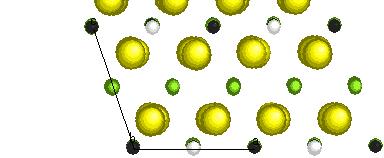
17 Chapter 6 Review on the Li[NixLi1/3-2x/3Mn2/3-x/3]O2 System CHAPTER 6 REVIEW ON THE LI[NIXLI1/3-2X/3MN2/3-X/3]O2 SYSTEM 6.1 Synthesis, Structure and Electrochemical Performance Among the novel lithium intercalation compounds, layered O3 lithium nickel manganese oxides Li[NixLi1/3-2x/3Mn2/3-x/3]O2 are considered as one of the most promising candidates for future lithium ion batteries. [1, 2] In this series, only the structure of the end member Li2MnO3 (x = 0) is known in detail. It consists of a pure Li layer alternating with a Li1/3Mn2/3 layer in which Li and Mn are ordered to form a 3ahex. 3ahex. superlattice. In the single crystal the stacking sequence of these ordered planes is a1c1, forming a structure with space group C2/m as illustrated in Figure 6-1. Generally, Li2MnO3 is considered as electrochemically inactive since charge compensation is unlikely to happen on Mn4+. However, Robertson & Bruce recently demonstrate that at 4.6V, some electrochemical activity is found in Li2MnO3. The proposed mechanisms for lithium extraction are possible proton exchange or oxygen loss, but not redox reaction of Mn4+/Mn5+. LiNi1/2Mn1/2O2 represents the other end member of the solid solution Li[NixLi1/3-2x/3Mn2/3-x/3]O2 (x = 1/2), its structure is still subject to debate. In LiNi1/2Mn1/2O2 Ni can be oxidized from 2+ to 4+; half of the transition metal is electrochemically inactive Mn4+. This material is most attractive since it has the highest theoretical capacity in the composition range 280mAh/g. However experimentally, this material exhibits different capacity and cycling performance with different preparation methods. Li2MnO3 is usually obtained through solid-state reaction of Li2CO3 and MnCO3; 121
18 Chapter 6 Review on the Li[NixLi1/3-2x/3Mn2/3-x/3]O2 System other members in the system, such as LiNi1/2Mn1/2O2 are often synthesized by coprecipitation or sol-gel methods, followed by high-temperature firing C. c1 A B C a1 Li/Mn Li O 3bmon. amon. amon. x 3bmon. amon. bmon. amon. x bmon. Mn4+ Li+ Fiugre 6-1 a) Crystal structure of Li2MnO3 b) (001)hex. projection of Li1/3Mn2/3 layer. Ohzuku and Makimura obtained a reversible capacity of 200 Ah/Kg between the potential window V and a good cycling efficiency up to 30 cycles [1]. J.Dahn s group reported a stable capacity of 140 Ah/Kg in 3 to 4.4V and 200Ah/Kg in 2.5 to 4.8V [3]. The structure of LiNi1/2Mn1/2O2 is usually indexed as a rhombohedral layered structure with space group R-3m. The separation of Li and transition metals in different layers is not perfect in LiNi1/2Mn1/2O2, as Rietveld refinement of the structure based on the XRD and neutron diffraction data gives 8 to 10 percent Ni ions in the Li layer [1, 3]. Such mixing is naturally accompanied by the presence of Li ions in the transition metal (Ni, Mn) layers, which has been revealed by 6Li MAS NMR studies[4, 5]. It is confirmed both by XANES 122
19 Chapter 6 Review on the Li[NixLi1/3-2x/3Mn2/3-x/3]O2 System experiment and first-principles calculations that in LiNi1/2Mn1/2O2, the delithiation process occurs by oxidizing Ni2+ first to Ni3+, and then when all the Ni2+ are oxidized, Ni3+ ions will be oxidized to Ni4+.[6, 7] From powder XRD studies, superstructure lattice peak were observed for compounds with 0 x 1/3 in Li[NixLi1/3-2x/3Mn2/3-x/3]O2 [9]. Lu & Dahn proposed that for such compositions, Ni, Mn and Li ions are ordered in the transition metal layer on a 3ahex. 3ahex. superlattice. They reported that ordering is not expected for the composition x = 1/2 as X-ray and neutron powder diffraction analyses reveal little evidence of superlattice peaks [8]. However, recent first-principles computation and Li-NMR analyses [5] reveal strong ordering interactions between Ni2+ & Mn4+ and Li+ & Mn4+, even for the composition LiNi1/2Mn1/2O2. Monte Carlo simulations on perfectly stoichiometric material with no Li/Ni interlayer displacement show that short range ordering of Ni2+ and Mn4+ is retained near synthesis temperature range, though these simulations do not account for the presence of Li in the transition-metal layer [5]. NMR data reveals the preference for Li in the transition metal layers to be surrounded by 5-6 Mn. [5] Moreover, recent electron diffraction data of a LiNi1/2Mn1/2O2 sample by Ohzuku et al. clearly shows a 3ahex. 3ahex. superstructure relative to the parent hexagonal cell, but a detailed structural model was not discussed [9]. More recently, Van der Ven and Ceder proposed a structural arrangement in which cation layers with stoichiometry Li11/12Ni1/12 alternate with Li1/12Ni5/12Mn6/12 in the octahedral sites of the O3 layered structure [10]. In the layer with composition Li1/12Ni5/12Mn6/12 the cations arrange in flower-like patterns, which will be described in details later. 123
20 Chapter Anomalous Capacity when 0 Review on the Li[NixLi1/3-2x/3Mn2/3-x/3]O2 System x < 1/2 It is well known that lithium can be extracted from lithium manganese oxides by oxidizing Mn up to 4+. However, Li[NixLi1/3-2x/3Mn2/3-x/3]O2 (0 x < 1/2) in which Mn already has 4+ oxidation state, demonstrated overcharge beyond Mn4+ when the materials were charged beyond 4.5V [11, 12]. The amount of lithium extracted beyond the theoretical amount is referred to as anomalous capacity, since the possible causes for such behavior have not been clearly identified. For x < 1/2 compounds, some irreversible change occurred in the electrodes charged to 4.8V. A charge-discharge curve of Li2MnO3 by Robertson and Bruce (Figure 6-2) depicts the overcharging behavior clearly. A plateau near 4.6V is present. Near the plateau, the lattice parameter a remains almost constant, while c reduces rapidly [3, 12] Lu et al. claimed that the transition metal oxidation states are not changing during the plateau because a axis remains approximately constant; and the rapid decrease in c axis suggests that most of the Li is being removed from Li layer. Therefore, the charge compensation must come from the oxygen atom, which is effectively Li2O is lost. Further oxygen extraction (during subsequent cycles) must be accompanied by Mn reduction. (Mn4+ > Mn3+ below 3.5V). Such a large amount of oxygen loss may also cause substantial motion of the transition metal to the lithium layer, leading to poor lithium diffusion and large irreversible capacity. When the cells are charged between V, no anomalous behavior is observed. Their in-situ XRD experiment shows that all changes are completely reversible, as expected in the intercalation process. 124
21 Chapter 6 Review on the Li[NixLi1/3-2x/3Mn2/3-x/3]O2 System Another end member of the solid solution Li2MnO3 (x = 0) was investigated by Robertson & Bruce [11, 13]. They suggested that many electrolytes contain H+ due to the presence of PF6- anion, thus proton exchange with Li+ may occur. They also claimed that oxygen loss appears to dominate during the overcharge of Li[NixLi1/32x/3Mn2/3-x/3]O2 (0 < x < 1/2) though H+/Li+ exchange is also evident. From the ex- situ XRD data of overcharged Li2MnO3, it was found that when H+/Li+ exchange occurred, the O3 structure (ABC stacking of oxygen layers) transformed to a P3 structure based on close-packed oxide layers stacked in AABBCC sequences [11]. The driving force for the adoption of this structure is the hydrogen bonding between adjacent oxide ion layers. Figure 6-2 [11] First charge discharge curve of cells at different temperatures for Li2MnO3 prepared at a) 500 C and b) 800 C 6.3 Other Observations for LiNi1/2Mn1/2O2 Shaju et al. [14] attempted a detailed study of LiNi1/2Mn1/2O2 by GITT (Galvanic Intermittent Titration Technique) and EIS (Electrochemical Impedance 125
22 Chapter 6 Review on the Li[NixLi1/3-2x/3Mn2/3-x/3]O2 System Spectroscopy). The GITT Diffusivity of Li was measured to be about 3*10-10 cm2/s in the voltage range of 3.8V to 4.3V (minimum at 3.8V, which indicates some structural change at this voltage). EIS Impedance study shows a decrease in impedance at the start of charging, a minimum value is reached at 3.8V and then charge transfer resistance increases as the state of charge (SOC) increases. Bulk and surface resistance remain almost constant throughout the charging. According to the authors, the capacity fading when charged above 4.3V is due to the increased polarization at the end of the charging. Many possible reasons for polarization have been proposed [14]: 1. Poor electronic charge-transfer due to unavailability of redox pair 2. Cation mixing 3. Phase change 4. Surface film, etc. Various experimental and computational groups have investigated the above speculations; nevertheless ambiguity still exists in the characterization of charged LiNi1/2Mn1/2O2. The following experimental facts were observed as well: The parent structure R-3m changes to C2/m at half-delithiation Li0.5Ni1/2Mn1/2O2 [6] Most of Li go to tetrahedral sites at half-delithiation [15] Charge rates are important for the reversible capacity; 152mAh/g between 2.8V-4.3V with excellent cycleability is achieved if 10mA/g charge density 126
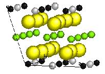
23 Chapter 6 Review on the Li[NixLi1/3-2x/3Mn2/3-x/3]O2 System is applied. [16], only 87mAh/g can be obtained if the current density applied is 100mA/g [17]. After 50 cycles, the R-3m frame is preserved, though the ordering has disappeared. [16] Short-range ordering disappears after a few cycles by NMR study (C.P.Grey, personal communication) Co, Al, Ti doping improve the reversible capacity and cycling ability [18] 6.4 First Principles and Monte Carlo Study in the System Modeling of LiNi1/2Mn1/2O2 was performed by first principles computations assuming that no Li is present in the transition metal layer [5]. The arrangement of Ni and Mn in the transition metal layer that has the lowest energy is the zig-zag ordering shown in Figure 6-3, in clear disagreement with experiments [19, 20]. However, this preliminary computation study does give some useful insight into the long and short-range order in LiNi1/2Mn1/2O2. There is strong tendency for Ni2+ and Mn4+ to have long-range ordering on a triangular lattice. The kinetic Monte Carlo study shows that even when the material is synthesized above the long-range ordering temperature, short-range order exists and can grow as the material is cooled. Figure 6-3 [5] Zig-zag in-plane ordering of Ni and Mn in LiNi1/2Mn1/2O2 127
24 Chapter 6 Review on the Li[NixLi1/3-2x/3Mn2/3-x/3]O2 System In a more recent study by Van der Ven and Ceder, Li is included in the transition metal layer for the computational study [10]. Using the results from ab initio computations with various Li, Ni and Mn arrangements, they predicted a flowertype ordering of Ni, Mn and Li in a 2 3ahex. 2 3ahex. unit cell with Li1/12Ni5/12Mn1/2 stoichiometry layer of LiNi1/2Mn1/2O2 (assuming there is 9% of Li in the transition metal layer), as shown in Figure 6-4. Each Li is surrounded by a hexagon of six Mn, which in turn is surrounded by a larger hexagon of twelve Ni. The similarity and difference between such flower ordering and the 3ahex. 3ahex. ordering will be discussed in detail in Chapter 8 in combination with experimental and simulation results. Mn Ni Li Figure 6-4 Flower in-plane ordering [5] of Ni and Mn in Li11/12Ni1/12[Li1/12Ni5/12Mn1/2]O2 (i.e. LiNi1/2Mn1/2O2). In addition, a combined study by first principles calculations and Li NMR spectroscopy on Li[NixLi1/3-2x/3Mn2/3-x/3]O2 system [21] shows that the lithium ions in the transition metal layer participate in the electrochemical process. They return to the sites upon lithium re-intercalation, though become increasingly unstable when the concentration of vacancies in the lithium layers increases. The octahedral lithium 128
25 Chapter 6 Review on the Li[NixLi1/3-2x/3Mn2/3-x/3]O2 System nearby three vacancies in the lithium layers is susceptible to migrate to the adjacent tetrahedral site in the lithium layer since no activation barrier exists for such process. [21] This proposed mechanism provides insight in understanding the capacity retention in the system. 6.5 Motivation and Objectives A detailed understanding of the atomic arrangement in the solid solution will be essential in obtaining the structure synthesis properties relations. Optimization of the electrode materials and design of new electrode materials depend strongly on such knowledge. For this work, the main objective is to identify the threedimensional crystal structures of Li[NixLi1/3-2x/3Mn2/3-x/3]O2, especially the two end members LiNi1/2Mn1/2O2 (x = 1/2) and Li2MnO3 (x = 0), as well as to study the effect of compositions and synthesis conditions on long-range cationic ordering in the system. 129
26 Chapter 6 Review on the Li[NixLi1/3-2x/3Mn2/3-x/3]O2 System References: T. Ohzuku and Y. Makimura, Layered lithium insertion material of LiNi1/2Mn1/2O2: A possible alternative to LiCoO2 for advanced lithium-ion batteries. Chemistry Letters, 2001(8): p Z.H. Lu, D.D. MacNeil, and J.R. Dahn, Layered cathode materials LiNixLi(1/3-2x/3)Mn(2/3-x/3)O2 for lithium-ion batteries. Electrochemical and Solid State Letters, (11): p. A191-A194. Z.H. Lu, et al., Synthesis, structure, and electrochemical behavior of Li NixLi1/3-2x/3Mn2/3-x/3O2. Journal of the Electrochemical Society, (6): p. A778-A791. W.S. Yoon, et al., Li-6 MAS NMR and in situ X-ray studies of lithium nickel manganese oxides. Journal of Power Sources, : p W.S. Yoon, et al., Local structure and cation ordering in O3 lithium nickel manganese oxides with stoichiometry LiNixMn(2-x)/3Li(1-2x)/3O2 - NMR studies and first principles calculations. Electrochemical and Solid State Letters, (7): p. A167-A171. Y. Arachi, et al., Structural change of Li1-xNi0.5Mn0.5O2 cathode materials for lithium-ion batteries by synchrotron radiation. Chemistry Letters, (1): p J. Reed and G. Ceder, Charge, potential, and phase stability of layered Li(Ni0.5Mn0.5)O2. Electrochemical and Solid-State Letters, (7): p. A145. Z.H. Lu, Z.H. Chen, and J.R. Dahn, Lack of cation clustering in LiNixLi1/31/2) and LiCrxLi(1-x)/3Mn(2-2x)/3O2 (0 < x < 1). 2x/3Mn2/3-x/3O2 (0 < x Chemistry of Materials, (16): p T. Ohzuku and Y. Makimura. Structural Chemistry and Electrochemistry of LiNi1/2Mn1/2O2 for Advanced Lithium Batteries. in Abstract No of the Electrochemical Society Spring Meeting Paris, France. A. Van der Ven and G. Ceder, Ordering in Lix(Ni0.5Mn0.5)O2 and its relation to charge capacity and electrochemical behavior in rechargeable lithium batteries. Electrochemistry Communications, : p A.D. Robertson and P.G. Bruce, Mechanism of electrochemical activity in Li2MnO3. Chemistry of Materials, (10): p Z.H. Lu and J.R. Dahn, Understanding the anomalous capacity of Li/LiNixLi(1/3-2x/3)Mn(2/3-x/3)O2 cells using in situ X-ray diffraction and electrochemical studies. Journal of the Electrochemical Society, (7): p. A815-A822. A.D. Robertson and P.G. Bruce, The origin of electrochemical activity in Li2MnO3. Chemical Communications, 2002(23): p K.M. Shaju, G.V.S. Rao, and B.V.R. Chowdari, Li-ion kinetics and polarization effect on the electrochemical performance of Li(Ni1/2Mn1/2)O2. Electrochimica Acta, (9-10): p H. Kobayashi, et al., Structural determination of Li1-yNi0.5Mn0.5O2 (y=0.5) using a combination of Rietveld analysis and the maximum entropy method. Journal of Materials Chemistry, (1): p Y.K. Sun, C.S. Yoon, and Y.S. Lee, Electrochemical properties and structural characterization of layered Li Ni0.5Mn0.5O2 cathode materials. Electrochimica Acta, (18): p
27 Chapter Review on the Li[NixLi1/3-2x/3Mn2/3-x/3]O2 System B.L. Cushing and J.B. Goodenough, Influence of carbon coating on the performance of a LiMn0.5Ni0.5O2 cathode. Solid State Sciences, (1112): p S.H. Kang, et al., Layered Li(Ni0.5-xMn0.5-xM '(2x))O2 (M ' = Co, Al, Ti; x = 0, 0.025) cathode materials for Li-ion rechargeable batteries. Journal of Power Sources, (1): p Y. Makimura, N. Nakayama, and T. Ohzuku. Structural Chemistry and Electrochemistry of LiNi1/2Mn1/2O2 for Advanced Lithium Batteries. in The Electrochemical Society Meeting Paris France. Y.S. Meng, G. Ceder, C.P. Grey, W.-S. Yoon, and Y. Shao-Horn, Understanding the Crystal Structure of Layered LiNi0.5Mn0.5O2 by Electron Diffraction and Powder Diffraction Simulation. Electrochemical and Solid State Letters, (6): p. A155. C.P. Grey, et al., Electrochemical Activity of Li in the Transition-Metal Sites of O3 Li[Li(1-2x)/3Mn(2-x)/3Nix]O2. Electrochemical and Solid State Letters, (9): p. A290-A
28 Chapter 7 Kinematics of Diffraction TEM, XRD and ND CHAPTER 7 KINEMATICS OF DIFFRACTION TEM, XRD AND ND Knowledge on how atoms are arranged into crystal structures is the foundation by which we gain our understanding of the synthesis, microstructures and properties of materials. Diffraction techniques have been applied for crystal structure analysis in materials science over a few decades and can be broadly categorized into powder diffraction and single crystal diffraction. Most common radiation sources of diffraction experiment are X-ray (soft and hard), neutron and electron. It is tempting to give a unified treatment to the X-ray, neutron and electron diffraction. However such complete theoretical explanation of diffraction physics is beyond the scope of this thesis. The simple theoretical and practical issues for those techniques are discussed in this chapter; the unique advantages of each diffraction technique as well as its limitations will be explained in detail. And the message that none of the diffraction technique should be used in isolation to solve a materials problem will hopefully be clear. In this work we will demonstrate how the combination of all help to characterize the atomic arrangement of lithium nickels manganese oxides, which is essential in understanding and optimizing the materials electrochemical properties. 132
29 Chapter Kinematics of Diffraction TEM, XRD and ND Different Sources of Radiation and Their Interaction with Matter Simply speaking, diffraction is a three-dimensional extension of simple Fraunhofer (far-field) diffraction theory applied to the idealized case of infinite periodic object with sharply defined diffracted beam and a set of lattice points in reciprocal space [1]. The basic mathematical tool used is Fourier series. However, greater sophistications exist for different radiation sources since they interact with matter differently. X-rays X-rays are generated when energetic electrons lose energy. There are two major sources for X-rays: synchrotron radiation and cathode ray tube. The former offers higher intensity and better resolution, however in laboratory scale, the latter is widely used. Facilities for synchrotron radiation experiments are available only at several national/international laboratories. Conventional X-ray tubes are vacuum tube diodes, where their filaments are biased typically at a few tens of kv. Electrons are emitted thermoionically from the filament, and accelerate into the anode, where X-rays are generated. The characteristic wavelengths of X-rays vary from 2.28 Å for chromium to 0.71 Å for molybdenum, the most commonly used being the copper radiation of wavelength 1.54 Å. X-rays are scattered by the electrons in a material through the interaction between the negatively charged electrons and the electromagnetic field of the incident X-rays [2]. The electrons in the material respond to the applied field of the X-ray flux, 133
30 Chapter 7 Kinematics of Diffraction TEM, XRD and ND oscillating with the frequency of the X-ray beam. These accelerated charged particles emit their own electromagnetic field, thus the resultant field is called the scattered wave [2, 3]. For light elements, for example oxygen, whose electron density is weak, it is extremely difficult, if not impossible to directly determine the position of light atoms by X-rays. Electrons For many years, the electron source was a sharply-bent tungsten wire being electrically heated. At high enough temperatures, thermoioinc emission occurs and electrons are emitted. The rate of the thermoioinc emission is proportional to exp(/kt), where is the work function of tungsten. ( for tungsten is 4.5eV). The lower work function of LaB6 (2.7eV) has made it a preferred material for thermoioinc electron guns, though the cost of LaB6 is much higher than that of tungsten. On the other hand, cold field emission gun (FEG) is an excellent point source of radiation, it is highly monochromatic and is absent of thermal spread. A positive electrode is placed near a sharp metal tip (usually tungsten), a strong electric field at the tip causes some electrons to overcome the work function and leave the metal. Nevertheless, cold FEG guns require ultrahigh vacuum system ( Pa) in order to suppress the damage by ions of gas atoms that accelerated into the tip in the high electric field imposed. Electrons are scattered by both the electrons and the nuclei in a material; it is not a field-to-field exchange as in the case of X-rays. Therefore, electrons are scattered much more strongly than X-rays. [3, 4] However, the requirement of specimen and 134
31 Chapter 7 Kinematics of Diffraction TEM, XRD and ND dynamic effects make ED a less conventional technique in structural analysis as XRD. Neutrons The neutrons for diffraction experiments are usually the thermal neutrons which are in thermal equilibrium with the atoms in a nuclear reactor. They have an average energy of about 0.025eV; however, the spread of energies or wavelengths in the beam of neutrons obtained from a reactor is quite broad. For diffraction experiment, a narrow range of wavelength is selected by use of a monochromator crystal or by a time-of-flight chopper device which selects a range of neutron velocities. The main interaction of a matter with neutron is with the nucleus. Neutrons are not appreciably scattered by the electrons of a matter. [1] Neutron diffraction is not only suitable for structural analysis, especially for locating light elements; but also excellent for studying time-dependent processes, such as phonons and magnons. The kinematics is derived mainly in the context of nuclear physics. A different set of jargon is used, for instance, scattering cross section rather than atomic scattering amplitude is used in neutron diffraction analysis. Despite the different physical mechanisms in the three diffraction processes, together they provide complementary information about the atomic arrangements in materials. There are a lot of similarities in these three diffraction techniques; the most well known one is Bragg s law [2], which will be discussed next. 135
32 Chapter Kinematics of Diffraction TEM, XRD and ND Simple Diffraction Physics The Bragg s Law and Laue Condition In the geometric optics approximation for diffraction, Bragg s law is stated as n = 2 dhkl sin where n is the order of reflection. Eq. 7-1 is the wavelength of the incident wave, d is the spacing of particular set of crystallographic planes and is the angle between the incident beam and the crystallographic planes, as shown in Figure 7-1. The right hand side sets the difference in path length for the ray scattered from plane A and the ray scattered from the plane B. The left hand side gives the condition for constructive interference (and therefore strong diffraction). Figure 7-1 Schematics of X-ray diffraction by planes of atoms Diffraction is a wave interference phenomenon and it is more appropriate to express the diffraction condition in terms of wave vectors. Suppose that the incident wave vector k 0 and the scattered wave vector have the same length (that is elastic scattering), the angle between k and k 0 is equivalent to the 2 k k k0 2 k sin 4 sin in the Bragg s law. Eq
33 Chapter 7 Notice that Kinematics of Diffraction TEM, XRD and ND k is the normal of the diffraction planes, as shown in Figure 7-2. This is called the Laue condition [3] and is more effective to use in diffraction physics. k ksin k k0 Diffraction Planes Figure 7-2 Relationship between k and for elastic scattering Real and Reciprocal Space The kinematical scattering amplitudes can be expressed in terms of the Fourier transform of a distribution of electron density in real space.[1] The Fourier transform space is often referred to as the reciprocal space. It is much more convenient to understand the diffraction effects in terms of reciprocal lattice. In real space, a position vector r has coordinates (x,y,z), in reciprocal lattice, a position vector u has coordinates (u,v,w). A distribution of electron density in real space can be expressed as F (u ) ( r ) exp 2 i u r d r Eq. 7-3 If the electron density distribution is assumed to be the sum of the electron density attributed by individual atoms, then F (u ) f i ( u ) exp 2 i u ri Eq. 7-4 i 137
34 Chapter 7 Kinematics of Diffraction TEM, XRD and ND The values for atomic scattering factor can be found in the International Tables for Crystallography Vol. C [5]. For a periodic lattice in real space with lattice parameters a, b, c, the corresponding reciprocal lattice is associated with a*, b*, c*. The relations are: a b c,b V c a,c V a b V where V is the unit cell volume. In the case of orthogonal lattice, a* = 1/a, b*= 1/b and c*= 1/c. Diffraction occurs when k is a vector of the reciprocal lattice Ewald Sphere Construction The Laue condition for diffraction can be demonstrated by a geometrical construction, named the Ewald Sphere Construction [2]. Assume that the reciprocal lattice is simple cubic, as shown in Figure 7-3, the incident wave vector k0 and possible diffracted wave vector k are shown in the picture. k0 is always placed at a point of the reciprocal lattice, thus the condition k = 0 always satisfies the Laue condition. This is the reason why a forward-scattered beam in the electron diffraction pattern is always observed. In elastic scattering, the length of k equals the length of k0, which is the radius of the Ewald sphere. If the end of the k touches a reciprocal lattice point, the Laue diffraction condition occurs. 138
35 Chapter 7 Kinematics of Diffraction TEM, XRD and ND z y x k k0 Ewald Sphere R = 1/ k k k0 Figure 7-3 Ewald sphere construction In X-ray diffraction, the length of k0, which is in the order of 1/ (about 1Å-1) is comparable to the reciprocal lattice spacing. The Ewald sphere is strongly curved. For electron diffraction, however, the length of the wave vector is much longer than the reciprocal lattice (the wave length of 200keV electrons is about Å), the Ewald sphere is relatively flat. Therefore, k is nearly perpendicular to k0. In practice, the diffraction intensity is distributed around a reciprocal lattice point with finite volume, so k does not have to exactly equal a reciprocal lattice for diffraction to occur Perfect and Defective Crystal The translational symmetry of unit cells on a lattice is the essential feature of the crystal that enables constructive interferences of wavelets emitted by many atoms. 139
36 Chapter 7 Kinematics of Diffraction TEM, XRD and ND Although real crystals contain many types of defects, including point defects, dislocations, stacking faults etc., which may or may not destroy the translational symmetry of the crystal, it is reasonable to think the main diffraction effects as coming from an ideally periodic crystal Kinematical Approximation and Dynamic Diffraction Kinematical approximation is also known as single scattering approximation. Coherent multiple scattering is called dynamical diffraction. [1] The condition for kinematical diffraction implies that the amplitude of the single scattered radiation is very small compared with the incident wave amplitude and the amplitude of the doubly- and multiply-scattered radiation is negligible compared with the singly scattered. The limit of the applicability of kinematical approximation depends very much on the radiation source. [1, 3] In the case of x-rays and neutrons, the interaction with atoms is so weak that the energy associated with diffracted waves can be concentrated into one or two sharply defined directions by three-dimensional diffraction before the incident beam loses much energy. Doubly or multiple diffraction occurs only if another crystal region (perfectly ordered, in absent of defects) is set at the right angle for Bragg condition, which is seldom satisfied since the radius of the Ewald sphere is comparable to the reciprocal lattice. While for electron diffraction, the interaction with atoms is much stronger so that multiple scattering may not be ignored. Well defined diffracted beams are not generated before the incident beam loses its energy. Multiply scattering becomes important with a distance in the order of one or two hundred Armstrong for light atoms and less for heavy atoms. Fortunately, coherent multiple scattering has been 140
37 Chapter 7 Kinematics of Diffraction TEM, XRD and ND satisfactorily taken care of for experiments by the use of special theoretical treatments.[6-8] 7.3 Powder Diffraction vs. Single Crystal Diffraction Both powder and single crystal diffraction are used in structural analysis. However, structure determination from powder diffraction data is much more difficult than from single crystal diffraction data. This is associated almost entirely with the collapse of the three dimensions of crystallographic information onto the single dimension of a powder diffraction pattern. [9] If representative single crystals are available, the single crystal diffraction is the preferred method. The reason that powder diffraction is always used for structure analysis is that there are many materials for which no single crystals are easily available. However, when only powder sample is available, there may be small crystallites that are suitable for single crystal diffraction, if a suitable technique such as selected area electron diffraction (SEAD) is applied. These small crystals do, however, suffer from the risk that they may not be representative of the bulk powder. Therefore, it is essential to collect a powder diffraction pattern as well as that the structure information obtained from the microcrystallites corresponding to that of the bulk material. 7.4 The Structure Determination Process The structure determination process can be viewed as an optimization process. Sample quality, type of radiation source to use, suitable experimental conditions, determination of the space group, fitting all the structural parameters and so on, have to be optimized with respect to the type of sample itself. To be relevant to this work, 141
38 Chapter 7 Kinematics of Diffraction TEM, XRD and ND the structure determination process for lithium nickel manganese oxides is illustrated in the flow chart below in Figure 7-4. The Rietveld method [10], which is an achievement that has greatly enhanced the power of the powder diffraction experiments, has been widely used in the structural analysis. However, the Rietveld method is a refinement process, thus it requires that an approximation to the correct structure be known in advance. If a structural model is not available, it must first be determined. The same is true for fitting single-crystal electron diffraction patterns. Thus, chemical information and structural information obtained from other techniques, including first principles computation, are necessary for the structure determination processes. 142
39 Chapter 7 Kinematics of Diffraction TEM, XRD and ND Sample Radiation Source powder XRD & single crystal ED Data Collection Proposed Structural Model Indexing & Space Group Determination Whole Profile Matching Simulating ED Patterns from Different Zone Axis Rietveld Refinement Matching Experimental ED Patterns Crystal Structure of the Sample Figure 7-4 The structure determination process 7.5 Selected Area Electron Diffraction The major experimental tool used in this part of the work is Selected Area Electron Diffraction (SAED). A detailed description on the SEAD technique is given, including its advantages and limitations. It is important to realize that a combination of experimental techniques that probe different relevant length scales is necessary to 143
40 Chapter 7 Kinematics of Diffraction TEM, XRD and ND truly understand the structure of complex solids such as Li[NixLi1/3-2x/3Mn2/3-x/3]O2 system. The role of computer simulation of electron diffraction is also explained in this chapter. A modern TEM provides two modes for obtaining diffraction patterns from individual crystallites Selected area electron diffraction (SAED) and convergentbeam electron diffraction (CBED). The former is useful for obtaining diffraction patterns from regions as small as 0.5µm in diameter; the latter is also called nanodiffraction, where a focused electron probe beam is used to obtain diffraction patterns from regions as small as 10Å. We are emphasizing SAED here, since we use it in this work. The ray diagram for TEM when it is operating in SAED mode is shown in Figure 75. The intermediate lens is focused on the back focal plane of the objective lens and the transmitted beam and all the diffracted beams are imaged. A second aperture (selected area aperture) is positioned in the image plane of the objective lens, as a means of confining the diffraction pattern to a selected area of the specimen. The specimen is first examined in image mode until a region of interest (or individual crystallite) is found. The selected area aperture is then inserted and positioned around this feature. The microscope is then switched to diffraction mode to obtain an electron diffraction pattern. 144
41 Chapter 7 Kinematics of Diffraction TEM, XRD and ND Specimen Objective Lens Back Focal Plane Intermediate Lens Image Plane Intermediate Lens Viewing Screen Figure 7-5 Selected Area Electron Diffraction (SAED) mode tracing the rays to confirm that the intermediate aperture provides a sampling of the transmitted and all diffracted rays [3] Dynamic Effect Dynamic diffraction is very important in electron diffraction, since the electron beam interacts so strongly with the atoms in the crystal. As shown in Figure 7-6, the beam that has been strongly Bragg-diffracted once is necessarily in the perfect Bragg orientation to be diffracted back into the direct beam by the same set of planes. This re-diffracted beam is perfectly oriented to be diffracted again. The likelihood of this process increases with the thickness of the specimen. Forbidden diffractions in low symmetry crystal may be observed when the specimens are of 145
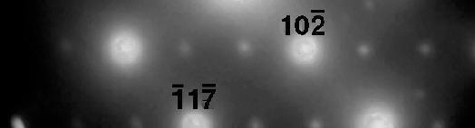
42 Chapter 7 Kinematics of Diffraction TEM, XRD and ND modest thickness and dynamic diffraction occurs [4]. Sometimes it is possible to perform a tilting experiment to test if double diffraction is occurring. Diffraction Planes Figure 7-6 The electron beam can be diffracted more than once a phenomenon called dynamical scattering Indexing of Electron Diffraction Pattern SAED patterns are sharply focused spot patterns. We will be talking about positions of diffraction spots and not their intensities for most of this thesis. The type of analysis differs from the X-ray studies, though much of the discussion of electron diffraction follows directly from the analysis of XRD. The reason that intensities of the spots are not measured is that the electron beams are diffracted more than one time in a typical TEM specimen [3, 4, 11]. We have discussed the major differences between the two radiation sources: electrons and X-rays in the previous chapter: Electrons have a much shorter wavelength than the X-rays (for laboratory research). 146
43 Chapter 7 Kinematics of Diffraction TEM, XRD and ND Electrons are scattered more strongly because they interact with both the nucleus and the electrons of the scattering atoms through Coulomb forces. Electron beams can be easily directed because electrons are charged particles. The indexing of single crystal diffraction patterns begins with the identification of the forward transmitted beam, followed by indexing two independent diffraction spots nearest the (000) spot. Once the indices of all diffraction spots are obtained, we can specify the zone axis the normal to the plane of the spot pattern. The indexing of a diffraction pattern is not unique. A high symmetry leads to a multiplicity of different, but equally correct ways to index a pattern. The procedures are straightforward for low-index zone axes of simple crystal structures, but becoming increasingly difficult for crystal structures with low symmetry and for high-index zone axes, where many different combinations of interplanary spacings and angles provide diffractions patterns that look similar. As we have mentioned in the previous chapter, indexing single crystal electron diffraction pattern requires that an approximation to the correct structure be known in advance Simulation of Electron Diffraction Pattern In many cases, it is helpful to use a computer program to calculate the diffraction patterns, especially in the simple case where only kinematics are considered. Interpretation of diffraction data can be routine and relatively straightforward or extremely complex depending on the type of structures. In order to figure out the 147
44 Chapter 7 Kinematics of Diffraction TEM, XRD and ND crystal structures of complex solids, such as Li[NixLi1/3-2x/3Mn2/3-x/3]O2 system, simulations of different structural models are compared with the experimentally obtained diffraction data. With Cerius2 [12], fast and interactive simulation radically increases the efficiency of diffraction data interpretation. Simulated patterns can be recalculated instantaneously as a structural model is modified or manipulated, allowing real-time coupling of structure modeling to experiment. In addition, changing diffractometer properties, the nature of the radiation, and simulation parameters is straightforward with Cerius2. 148
45 Chapter 7 Kinematics of Diffraction TEM, XRD and ND References: J.M. Cowley, Diffraction Physics. 1995, Amsterdam; New York: Elsevier Science B.V. B.D. Cullity, Elements of X-ray Diffraction. 2nd ed. 1978, Reading, Massachusetts: Addison-Wesley Pub. Co. B. Fultz and J.M. Howe, Transmission Electron Microscopy and Diffractometry of Materials. 2nd ed. 2002, New York: Springer. D.B. Williams and C.B. Carter, Transmission Electron Microscopy: A Textbook for Materials Science. Vol. V1-V , New York: Plenum Press. International Tables for Crystallography. Vol. C. 1983, D. Reidel Publishing Company. H.A. Bethe, Ann. Phys. Lpz, : p J.M. Cowley and A.F. Moddie, Acta Crystallographica, : p A.F. Moddie, J.M. Cowley, and P. Goodman, in International Tables for Crystallography. 1990, D. Reidel Publishing Company. p. Section 5.2. W.I.F. David, et al., Structure Determination from Powder Diffraction Data. 2002, Oxford University Press: New York. H. Rietveld, Journal of Applied Crystallography, : p J.M. Cowley, ed. Electron Diffraction Techniques. Vol , Oxford University Press: New York
46
47
48
49
50
51


52


53
54
55


56
57
58
59
60
61
62
63
64


65
66
67


68
69
70
71
72
73
74
75
76
77
78
79
80
81
82


83
Chapter 4: Bonding in Solids and Electronic Properties. Free electron theory
 Chapter 4: Bonding in Solids and Electronic Properties Free electron theory Consider free electrons in a metal an electron gas. regards a metal as a box in which electrons are free to move. assumes nuclei
V 11: Electron Diffraction
 Martin-Luther-University Halle-Wittenberg Institute of Physics Advanced Practical Lab Course V 11: Electron Diffraction An electron beam conditioned by an electron optical system is diffracted by a polycrystalline,
Structure of Surfaces
 Structure of Surfaces C Stepped surface Interference of two waves Bragg s law Path difference = AB+BC =2dsin ( =glancing angle) If, n =2dsin, constructive interference Ex) in a cubic lattice of unit cell
6. Computational Design of Energy-related Materials
 6. Computational Design of Energy-related Materials Contents 6.1 Atomistic Simulation Methods for Energy Materials 6.2 ab initio design of photovoltaic materials 6.3 Solid Ion Conductors for Fuel Cells
DIFFRACTION PHYSICS THIRD REVISED EDITION JOHN M. COWLEY. Regents' Professor enzeritus Arizona State University
 DIFFRACTION PHYSICS THIRD REVISED EDITION JOHN M. COWLEY Regents' Professor enzeritus Arizona State University 1995 ELSEVIER Amsterdam Lausanne New York Oxford Shannon Tokyo CONTENTS Preface to the first
Supporting Information. First-Principles Study: Tuning the Redox Behavior of Li-Rich
 Supporting Information First-Principles Study: Tuning the Redox Behavior of Li-Rich Layered Oxides by Chlorine Doping Huijun Yan 1, Biao Li 1, Zhen Yu 2, Wangsheng Chu 2, Dingguo Xia 1* 1 Beijing Key Laboratory
CH676 Physical Chemistry: Principles and Applications. CH676 Physical Chemistry: Principles and Applications
 CH676 Physical Chemistry: Principles and Applications Band Theory Fermi-Dirac Function f(e) = 1/[1 + e (E-E F)/kT ] Where the Fermi Energy, E F, is defined as the energy where f(e) = 1/2. That is to say
M2 TP. Low-Energy Electron Diffraction (LEED)
") M2 TP Low-Energy Electron Diffraction (LEED) Guide for report preparation I. Introduction: Elastic scattering or diffraction of electrons is the standard technique in surface science for obtaining structural
M2 TP Low-Energy Electron Diffraction (LEED) Guide for report preparation I. Introduction: Elastic scattering or diffraction of electrons is the standard technique in surface science for obtaining structural
An Introduction to Diffraction and Scattering. School of Chemistry The University of Sydney
 An Introduction to Diffraction and Scattering Brendan J. Kennedy School of Chemistry The University of Sydney 1) Strong forces 2) Weak forces Types of Forces 3) Electromagnetic forces 4) Gravity Types
The Solid State. Phase diagrams Crystals and symmetry Unit cells and packing Types of solid
 The Solid State Phase diagrams Crystals and symmetry Unit cells and packing Types of solid Learning objectives Apply phase diagrams to prediction of phase behaviour Describe distinguishing features of
Topics in the June 2006 Exam Paper for CHEM1901
 June 006 Topics in the June 006 Exam Paper for CHEM1901 Click on the links for resources on each topic. 006-J-: 006-J-3: 006-J-4: 006-J-5: 006-J-6: 006-J-7: 006-J-8: 006-J-9: 006-J-10: 006-J-11: 006-J-1:
First-principles investigation of phase stability in Li x CoO 2
 PHYSICAL REVIEW B VOLUME 58, NUMBER 6 1 AUGUST 1998-II First-principles investigation of phase stability in Li x CoO 2 A. Van der Ven, M. K. Aydinol, and G. Ceder Department of Materials Science and Engineering,
is the minimum stopping potential for which the current between the plates reduces to zero.
 Module 1 :Quantum Mechanics Chapter 2 : Introduction to Quantum ideas Introduction to Quantum ideas We will now consider some experiments and their implications, which introduce us to quantum ideas. The
Earth Solid Earth Rocks Minerals Atoms. How to make a mineral from the start of atoms?
 Earth Solid Earth Rocks Minerals Atoms How to make a mineral from the start of atoms? Formation of ions Ions excess or deficit of electrons relative to protons Anions net negative charge Cations net
A Combined Computational/Experimental Study on LiNi 1/3 Co 1/3 Mn 1/3 O 2
 3676 Chem. Mater. 2003, 15, 3676-3682 A Combined Computational/Experimental Study on LiNi 1/3 Co 1/3 Mn 1/3 O 2 B. J. Hwang,, Y. W. Tsai, D. Carlier, and G. Ceder*, Department of Chemical Engineering,
MOLECULAR DYNAMICS STUDY OF LITHIUM DIFFUSION IN LITHIUM-MANGANESE SPINEL CATHODE MATERIALS
 MOLECULAR DYNAMICS STUDY OF LITHIUM DIFFUSION IN LITHIUM-MANGANESE SPINEL CATHODE MATERIALS RANDALL T. CYGAN *, HENRY R. WESTRICH *, AND DANIEL H. DOUGHTY ** * Sandia National Laboratories, Geochemistry
ELEMENTARY BAND THEORY
 ELEMENTARY BAND THEORY PHYSICIST Solid state band Valence band, VB Conduction band, CB Fermi energy, E F Bloch orbital, delocalized n-doping p-doping Band gap, E g Direct band gap Indirect band gap Phonon
A COMPUTATIONAL INVESTIGATION OF MIGRATION ENTHALPIES AND ELECTRONIC STRUCTURE IN SrFeO 3-δ
 A COMPUTATIONAL INVESTIGATION OF MIGRATION ENTHALPIES AND ELECTRONIC STRUCTURE IN SrFeO 3-δ A. Predith and G. Ceder Massachusetts Institute of Technology Department of Materials Science and Engineering
Defense Technical Information Center Compilation Part Notice
 UNCLASSIFIED Defense Technical Information Center Compilation Part Notice ADP012658 TITLE: Synthesis of Nanosized Lithium Manganate For Lithium-ion Secondary Batteries DISTRIBUTION: Approved for public
Neutron and x-ray spectroscopy
 Neutron and x-ray spectroscopy B. Keimer Max-Planck-Institute for Solid State Research outline 1. self-contained introduction neutron scattering and spectroscopy x-ray scattering and spectroscopy 2. application
X-ray, Neutron and e-beam scattering
 X-ray, Neutron and e-beam scattering Introduction Why scattering? Diffraction basics Neutrons and x-rays Techniques Direct and reciprocal space Single crystals Powders CaFe 2 As 2 an example What is the
Chapter Six: X-Rays. 6.1 Discovery of X-rays
 Chapter Six: X-Rays 6.1 Discovery of X-rays In late 1895, a German physicist, W. C. Roentgen was working with a cathode ray tube in his laboratory. He was working with tubes similar to our fluorescent
X-ray practical: Crystallography
 X-ray practical: Crystallography Aim: To familiarise oneself with the operation of Tex-X-Ometer spectrometer and to use it to determine the lattice spacing in NaCl and LiF single crystals. Background:
Topics in the November 2014 Exam Paper for CHEM1101
 November 2014 Topics in the November 2014 Exam Paper for CHEM1101 Click on the links for resources on each topic. 2014-N-2: 2014-N-3: 2014-N-4: 2014-N-5: 2014-N-7: 2014-N-8: 2014-N-9: 2014-N-10: 2014-N-11:
COLORATION AND BLEACHING PHENOMENA OF AMORPHOUS WO 3 FILMS DUE TO THE ELECTROCHEMICAL INSERTION OF DIVALENT CATIONS
 Page 1 of 6 COLORATION AND BLEACHING PHENOMENA OF AMORPHOUS FILMS DUE TO THE ELECTROCHEMICAL INSERTION OF DIVALENT CATIONS Y. Domori, T. Nanba, Y. Miura Department of Environmental Chemistry and Materials,
SOLID STATE PHYSICS. Second Edition. John Wiley & Sons. J. R. Hook H. E. Hall. Department of Physics, University of Manchester
 SOLID STATE PHYSICS Second Edition J. R. Hook H. E. Hall Department of Physics, University of Manchester John Wiley & Sons CHICHESTER NEW YORK BRISBANE TORONTO SINGAPORE Contents Flow diagram Inside front
Basic structure of SEM
 Table of contents Basis structure of SEM SEM imaging modes Comparison of ordinary SEM and FESEM Electron behavior Electron matter interaction o Elastic interaction o Inelastic interaction o Interaction
Materials Science and Engineering R
 Materials Science and Engineering R 73 (2012) 51 65 Contents lists available at SciVerse ScienceDirect Materials Science and Engineering R jou r nal h o mep ag e: w ww.elsevier.co m /loc ate/m ser Recent
3.012 Structure An Introduction to X-ray Diffraction
 3.012 Structure An Introduction to X-ray Diffraction This handout summarizes some topics that are important for understanding x-ray diffraction. The following references provide a thorough explanation
First-principles studies of cation-doped spinel LiMn 2 O 4 for lithium ion batteries
 First-principles studies of cation-doped spinel LiMn 2 O 4 for lithium ion batteries Siqi Shi, 1 Ding-sheng Wang, 2 Sheng Meng, 2 Liquan Chen, 1 and Xuejie Huang 1, * 1 Nanoscale Physics and Devices Laboratory,
Ceramic Bonding. CaF 2 : large SiC: small
 Recall ceramic bonding: - Mixed ionic and covalent. - % ionic character ( f ) increases with difference in electronegativity Large vs small ionic bond character: Ceramic Bonding CaF : large SiC: small
Optical and Photonic Glasses. Lecture 15. Optical Properties - Polarization, Absorption and Color. Professor Rui Almeida
 Optical and Photonic Glasses : Optical Properties - Polarization, Absorption and Color Professor Rui Almeida International Materials Institute For New Functionality in Glass Lehigh University 21 µm 9.1
Structure and Dynamics : An Atomic View of Materials
 Structure and Dynamics : An Atomic View of Materials MARTIN T. DOVE Department ofearth Sciences University of Cambridge OXFORD UNIVERSITY PRESS Contents 1 Introduction 1 1.1 Observations 1 1.1.1 Microscopic
X-Ray Photoelectron Spectroscopy (XPS)-2
-2") X-Ray Photoelectron Spectroscopy (XPS)-2 Louis Scudiero http://www.wsu.edu/~scudiero; 5-2669 Fulmer 261A Electron Spectroscopy for Chemical Analysis (ESCA) The 3 step model: 1.Optical excitation 2.Transport
X-Ray Photoelectron Spectroscopy (XPS)-2 Louis Scudiero http://www.wsu.edu/~scudiero; 5-2669 Fulmer 261A Electron Spectroscopy for Chemical Analysis (ESCA) The 3 step model: 1.Optical excitation 2.Transport
Solid State electrochemistry
 Solid State electrochemistry edited by Peter G. Bruce Department of Chemistry, University of St Andrews, Scotland IH CAMBRIDGE ^pf UNIVERSITY PRESS 1 1.1 1.2 1.3 1.4 1.5 1.6 Preface Introduction P. G.
Supplementary Information
 Supplementary Information Supplementary Figure 1: Electronic Kohn-Sham potential profile of a charged monolayer MoTe 2 calculated using PBE-DFT. Plotted is the averaged electronic Kohn- Sham potential
Supplementary Figure 1 Structure of InHCF. a, Selected-area electron diffraction pattern of individual InHCF nanocube (scale bar 5 nm -1 ).
.") Supplementary Figure 1 Structure of InHCF. a, Selected-area electron diffraction pattern of individual InHCF nanocube (scale bar 5 nm -1 ). b and c, SEM and TEM image of InHCF/Gr (scale bar 100 nm). 1
Supplementary Figure 1 Structure of InHCF. a, Selected-area electron diffraction pattern of individual InHCF nanocube (scale bar 5 nm -1 ). b and c, SEM and TEM image of InHCF/Gr (scale bar 100 nm). 1
Materials Chemistry and Physics
 Materials Chemistry and Physics 117 (2009) 41 45 Contents lists available at ScienceDirect Materials Chemistry and Physics journal homepage: www.elsevier.com/locate/matchemphys Effects of different carbonate
Chapter 19: Electrochemistry
 Chapter 19: Electrochemistry Overview of the Chapter review oxidation-reduction chemistry basics galvanic cells spontaneous chemical reaction generates a voltage set-up of galvanic cell & identification
Handout 7 Reciprocal Space
 Handout 7 Reciprocal Space Useful concepts for the analysis of diffraction data http://homepages.utoledo.edu/clind/ Concepts versus reality Reflection from lattice planes is just a concept that helps us
Structural Understanding of Superior Battery Properties of Partially Ni-doped Li 2 MnO 3 as Cathode Material
 Structural Understanding of Superior Battery Properties of Partially Ni-doped Li 2 MnO 3 as Cathode Material Toshiyuki Matsunaga, *a Hideyuki Komatsu, a Keiji Shimoda, a Taketoshi Minato, a Masao Yonemura,
Ionic Bonding. Chem
 Whereas the term covalent implies sharing of electrons between atoms, the term ionic indicates that electrons are taken from one atom by another. The nature of ionic bonding is very different than that
SOLID STATE 18. Reciprocal Space
 SOLID STATE 8 Reciprocal Space Wave vectors and the concept of K-space can simplify the explanation of several properties of the solid state. They will be introduced to provide more information on diffraction
Y. W. Tsai, B. J. Hwang,*,, G. Ceder, H. S. Sheu, D. G. Liu, and J. F. Lee
 Chem. Mater. 2005, 17, 3191-3199 3191 In-Situ X-ray Absorption Spectroscopic Study on Variation of Electronic Transitions and Local Structure of LiNi 1/3 Co 1/3 Mn 1/3 O 2 Cathode Material during Electrochemical
Atomic Arrangement. Primer in Materials Spring
 Atomic Arrangement Primer in Materials Spring 2017 30.4.2017 1 Levels of atomic arrangements No order In gases, for example the atoms have no order, they are randomly distributed filling the volume to
Supplementary Information
 Supplementary Information Supplementary Figure 1. Photographs show the titration experiments by dropwise adding ~5 times number of moles of (a) LiOH and LiOH+H 2 O, (b) H 2 O 2 and H 2 O 2 +LiOH, (c) Li
Different states of a substance are different physical ways of packing its component particles:
 CHEM1011 Lecture 1 6 th March 2018 States of matter Different states of a substance are different physical ways of packing its component particles: solid (closely packed together and organized), liquid
Bonding and Packing: building crystalline solids
 Bonding and Packing: building crystalline solids The major forces of BONDING Gravitational forces: F = G m m 1 2 F = attractive forces between 2 bodies G = universal graviational constant (6.6767 * 10
Effects of Fluorine and Chromium Doping on the performance of Lithium-Rich Li 1+x MO 2 (M = Ni, Mn, Co) Positive Electrodes
 Positive Electrodes") Effects of Fluorine and Chromium Doping on the performance of Lithium-Rich Li 1+x MO 2 (M = Ni, Mn, Co) Positive Electrodes Wei Kong Pang, 1,2 Hsiu-Fen Lin, 3 Vanessa K. Peterson, 1,2* Cheng-Zhang Lu,
Effects of Fluorine and Chromium Doping on the performance of Lithium-Rich Li 1+x MO 2 (M = Ni, Mn, Co) Positive Electrodes Wei Kong Pang, 1,2 Hsiu-Fen Lin, 3 Vanessa K. Peterson, 1,2* Cheng-Zhang Lu,
Lecture 2: Atom and Bonding Semester /2013
 EMT 110 Engineering Materials Lecture 2: Atom and Bonding Semester 1 2012/2013 Atomic Structure Fundamental Concept Atoms are the structural unit of all engineering materials! Each atoms consist of nucleus
Supporting Information
 Supporting Information Anion Redox Chemistry in the Cobalt Free 3d Transition Metal Oxide Intercalation Electrode Li[Li 0.2 Ni 0.2 Mn 0.6 ]O 2 Kun Luo a, Matthew R. Roberts a, Niccoló Guerrini a, Nuria
Crystal Models. Figure 1.1 Section of a three-dimensional lattice.
 Crystal Models The Solid-State Structure of Metals and Ionic Compounds Objectives Understand the concept of the unit cell in crystalline solids. Construct models of unit cells for several metallic and
CHAPTER 3. Crystallography
 CHAPTER 3 Crystallography Atomic Structure Atoms are made of Protons: mass 1.00728 amu, +1 positive charge Neutrons: mass of 1.00867 amu, neutral Electrons: mass of 0.00055 amu, -1 negative charge (1 amu
Chem 728 Introduction to Solid Surfaces
 Chem 728 Introduction to Solid Surfaces Solids: hard; fracture; not compressible; molecules close to each other Liquids: molecules mobile, but quite close to each other Gases: molecules very mobile; compressible
Metallic and Ionic Structures and Bonding
 Metallic and Ionic Structures and Bonding Ionic compounds are formed between elements having an electronegativity difference of about 2.0 or greater. Simple ionic compounds are characterized by high melting
Self-compensating incorporation of Mn in Ga 1 x Mn x As
 Self-compensating incorporation of Mn in Ga 1 x Mn x As arxiv:cond-mat/0201131v1 [cond-mat.mtrl-sci] 9 Jan 2002 J. Mašek and F. Máca Institute of Physics, Academy of Sciences of the CR CZ-182 21 Praha
Chapter - 8. Summary and Conclusion
 Chapter - 8 Summary and Conclusion The present research explains the synthesis process of two transition metal oxide semiconductors SnO 2 and V 2 O 5 thin films with different morphologies and studies
Atomic Structure & Interatomic Bonding
 Atomic Structure & Interatomic Bonding Chapter Outline Review of Atomic Structure Atomic Bonding Atomic Structure Atoms are the smallest structural units of all solids, liquids & gases. Atom: The smallest
1. [7 points] Which element is oxidized in the reaction below? + O 2 + H 2 O
![1. [7 points] Which element is oxidized in the reaction below? + O 2 + H 2 O](/thumbs/78/77840959.jpg "1. [7 points] Which element is oxidized in the reaction below? + O 2 + H 2 O") 1. [7 points] Which element is oxidized in the reaction below? K 2 CrO 4 (aq) + BaCl 2 (aq) BaCrO 4 (s) + 2KCl a. Cl b. Cr c. O d. Ba e. This is not an oxidation-reduction reaction 2. [7 points] What are
1. [7 points] Which element is oxidized in the reaction below? K 2 CrO 4 (aq) + BaCl 2 (aq) BaCrO 4 (s) + 2KCl a. Cl b. Cr c. O d. Ba e. This is not an oxidation-reduction reaction 2. [7 points] What are
Classification of Solids, Fermi Level and Conductivity in Metals Dr. Anurag Srivastava
 Classification of Solids, Fermi Level and Conductivity in Metals Dr. Anurag Srivastava Web address: http://tiiciiitm.com/profanurag Email: profanurag@gmail.com Visit me: Room-110, Block-E, IIITM Campus
Basic Crystallography Part 1. Theory and Practice of X-ray Crystal Structure Determination
 Basic Crystallography Part 1 Theory and Practice of X-ray Crystal Structure Determination We have a crystal How do we get there? we want a structure! The Unit Cell Concept Ralph Krätzner Unit Cell Description
1. Nuclear Size. A typical atom radius is a few!10 "10 m (Angstroms). The nuclear radius is a few!10 "15 m (Fermi).
. The nuclear radius is a few!10 15 m (Fermi).") 1. Nuclear Size We have known since Rutherford s! " scattering work at Manchester in 1907, that almost all the mass of the atom is contained in a very small volume with high electric charge. Nucleus with
1. Nuclear Size We have known since Rutherford s! " scattering work at Manchester in 1907, that almost all the mass of the atom is contained in a very small volume with high electric charge. Nucleus with
E12 UNDERSTANDING CRYSTAL STRUCTURES
 E1 UNDERSTANDING CRYSTAL STRUCTURES 1 Introduction In this experiment, the structures of many elements and compounds are rationalized using simple packing models. The pre-work revises and extends the material
arxiv: v1 [cond-mat.mes-hall] 15 Aug 2014
![arxiv: v1 [cond-mat.mes-hall] 15 Aug 2014](/thumbs/89/97831186.jpg "arxiv: v1 [cond-mat.mes-hall] 15 Aug 2014") The potential applications of phosphorene as anode arxiv:1408.3488v1 [cond-mat.mes-hall] 15 Aug 2014 materials in Li-ion batteries Shijun Zhao,, and Wei Kang, HEDPS, Center for Applied Physics and Technology,
The potential applications of phosphorene as anode arxiv:1408.3488v1 [cond-mat.mes-hall] 15 Aug 2014 materials in Li-ion batteries Shijun Zhao,, and Wei Kang, HEDPS, Center for Applied Physics and Technology,
CHEM Principles of Chemistry II Chapter 10 - Liquids and Solids
 CHEM 1212 - Principles of Chemistry II Chapter 10 - Liquids and Solids 10.1 Intermolecular Forces recall intramolecular (within the molecule) bonding whereby atoms can form stable units called molecules
4. Inelastic Scattering
 1 4. Inelastic Scattering Some inelastic scattering processes A vast range of inelastic scattering processes can occur during illumination of a specimen with a highenergy electron beam. In principle, many
Experiment 7: Understanding Crystal Structures
 Experiment 7: Understanding Crystal Structures To do well in this laboratory experiment you need to be familiar with the concepts of lattice, crystal structure, unit cell, coordination number, the different
Structural characterization. Part 1
 Structural characterization Part 1 Experimental methods X-ray diffraction Electron diffraction Neutron diffraction Light diffraction EXAFS-Extended X- ray absorption fine structure XANES-X-ray absorption
Crystals, X-rays and Proteins
 Crystals, X-rays and Proteins Comprehensive Protein Crystallography Dennis Sherwood MA (Hons), MPhil, PhD Jon Cooper BA (Hons), PhD OXFORD UNIVERSITY PRESS Contents List of symbols xiv PART I FUNDAMENTALS
Direct Atomic-Scale Confirmation of Three-Phase Storage Mechanism in Li 4 Ti 5 O 12 Anodes for Room-Temperature Sodium-Ion Batteries
 SUPPLEMENTARY INFORMATION FOR Direct Atomic-Scale Confirmation of Three-Phase Storage Mechanism in Li 4 Ti 5 O 12 Anodes for Room-Temperature Sodium-Ion Batteries Authors: Yang Sun 1,*, Liang Zhao 1,*,
High-Resolution. Transmission. Electron Microscopy
 Part 4 High-Resolution Transmission Electron Microscopy 186 Significance high-resolution transmission electron microscopy (HRTEM): resolve object details smaller than 1nm (10 9 m) image the interior of
Chemistry: The Central Science. Chapter 20: Electrochemistry
 Chemistry: The Central Science Chapter 20: Electrochemistry Redox reaction power batteries Electrochemistry is the study of the relationships between electricity and chemical reactions o It includes the
Protocols for studying intercalation electrodes materials: Part II: Potentiodynamic Cycling with Galvanostatic Acceleration (PCGA)
") Electrochemistry - Application note n 2 Protocols for studying intercalation electrodes materials: Part II: Potentiodynamic Cycling with Galvanostatic Acceleration (PCGA) Available instruments for the
Electrochemistry - Application note n 2 Protocols for studying intercalation electrodes materials: Part II: Potentiodynamic Cycling with Galvanostatic Acceleration (PCGA) Available instruments for the
Oxygen vacancies enhance pseudocapacitive charge storage properties of MoO 3-x
 In the format provided by the authors and unedited. DOI: 10.1038/NMAT4810 Oxygen vacancies enhance pseudocapacitive charge storage properties of MoO 3-x Hyung-Seok Kim, 1 John B. Cook, 2,3 Hao Lin, 1 Jesse
Chapter 10: Modern Atomic Theory and the Periodic Table. How does atomic structure relate to the periodic table? 10.1 Electromagnetic Radiation
 Chapter 10: Modern Atomic Theory and the Periodic Table How does atomic structure relate to the periodic table? 10.1 Electromagnetic Radiation Electromagnetic (EM) radiation is a form of energy that exhibits
Supporting Information
 Supporting Information Figure S1. XRD patterns of ZnGa 2 O 4, GaN, ZnO, and Ga 2 O 3. Figure S2. SEM micrographs for ZnO (A), Ga 2 O 3 (B), GaN (C), ZnGa 2 O 4 (D). Figure S3A. Raman shifts associated
Solids. properties & structure
 Solids properties & structure Determining Crystal Structure crystalline solids have a very regular geometric arrangement of their particles the arrangement of the particles and distances between them is
The University of Hong Kong Department of Physics
 The University of Hong Kong Department of Physics Physics Laboratory PHYS3551 Introductory Solid State Physics Experiment No. 3551-2: Electron and Optical Diffraction Name: University No: This experiment
Chapter 4 Scintillation Detectors
 Med Phys 4RA3, 4RB3/6R03 Radioisotopes and Radiation Methodology 4-1 4.1. Basic principle of the scintillator Chapter 4 Scintillation Detectors Scintillator Light sensor Ionizing radiation Light (visible,
Crystal Structure and Electron Diffraction
 Crystal Structure and Electron Diffraction References: Kittel C.: Introduction to Solid State Physics, 8 th ed. Wiley 005 University of Michigan, PHY441-44 (Advanced Physics Laboratory Experiments, Electron
Chapter 10. Liquids and Solids
 Chapter 10 Liquids and Solids Chapter 10 Table of Contents 10.1 Intermolecular Forces 10.2 The Liquid State 10.3 An Introduction to Structures and Types of Solids 10.4 Structure and Bonding in Metals 10.5
Photoelectric Effect Experiment
 Experiment 1 Purpose The photoelectric effect is a key experiment in modern physics. In this experiment light is used to excite electrons that (given sufficient energy) can escape from a material producing
Lithium Batteries. Rechargeable batteries
 Lithium Batteries One of the main attractions of lithium as an anode material is its position as the most electronegative metal in the electrochemical series combined with its low density, thus offering
X-Ray Emission and Absorption
 X-Ray Emission and Absorption Author: Mike Nill Alex Bryant February 6, 20 Abstract X-rays were produced by two bench-top diffractometers using a copper target. Various nickel filters were placed in front
Imaging Methods: Scanning Force Microscopy (SFM / AFM)
") Imaging Methods: Scanning Force Microscopy (SFM / AFM) The atomic force microscope (AFM) probes the surface of a sample with a sharp tip, a couple of microns long and often less than 100 Å in diameter.
Imaging Methods: Scanning Force Microscopy (SFM / AFM) The atomic force microscope (AFM) probes the surface of a sample with a sharp tip, a couple of microns long and often less than 100 Å in diameter.
Chapter V: Interactions of neutrons with matter
 Chapter V: Interactions of neutrons with matter 1 Content of the chapter Introduction Interaction processes Interaction cross sections Moderation and neutrons path For more details see «Physique des Réacteurs
Röntgenpraktikum. M. Oehzelt. (based on the diploma thesis of T. Haber [1])
![Röntgenpraktikum. M. Oehzelt. (based on the diploma thesis of T. Haber [1])](/thumbs/91/106501237.jpg "Röntgenpraktikum. M. Oehzelt. (based on the diploma thesis of T. Haber [1])") Röntgenpraktikum M. Oehzelt (based on the diploma thesis of T. Haber [1]) October 21, 2004 Contents 1 Fundamentals 2 1.1 X-Ray Radiation......................... 2 1.1.1 Bremsstrahlung......................
Röntgenpraktikum M. Oehzelt (based on the diploma thesis of T. Haber [1]) October 21, 2004 Contents 1 Fundamentals 2 1.1 X-Ray Radiation......................... 2 1.1.1 Bremsstrahlung......................
X-Ray Photoelectron Spectroscopy (XPS)-2
-2") X-Ray Photoelectron Spectroscopy (XPS)-2 Louis Scudiero http://www.wsu.edu/~pchemlab ; 5-2669 Fulmer 261A Electron Spectroscopy for Chemical Analysis (ESCA) The 3 step model: 1.Optical excitation 2.Transport
X-Ray Photoelectron Spectroscopy (XPS)-2 Louis Scudiero http://www.wsu.edu/~pchemlab ; 5-2669 Fulmer 261A Electron Spectroscopy for Chemical Analysis (ESCA) The 3 step model: 1.Optical excitation 2.Transport
Mat E 272 Lecture 25: Electrical properties of materials
 Mat E 272 Lecture 25: Electrical properties of materials December 6, 2001 Introduction: Calcium and copper are both metals; Ca has a valence of +2 (2 electrons per atom) while Cu has a valence of +1 (1
X-RAY PRODUCTION. Prepared by:- EN KAMARUL AMIN BIN ABDULLAH
 X-RAY PRODUCTION Prepared by:- EN KAMARUL AMIN BIN ABDULLAH OBJECTIVES Discuss the process of x-ray being produced (conditions) Explain the principles of energy conversion in x-ray production (how energy
Extrinsic Defect Reactions in
 Chapter 5 Extrinsic Defect Reactions in Perovskite Materials The work presented in this Chapter has been published in Solid State Ionics [203]. 5.1 Introduction With dwindling fossil fuel reserves [204]
 CHAPTER 6 CHEMICAL BONDING SHORT QUESTION WITH ANSWERS Q.1 Dipole moments of chlorobenzene is 1.70 D and of chlorobenzene is 2.5 D while that of paradichlorbenzene is zero; why? Benzene has zero dipole
Resistance (R) Temperature (T)
 Temperature (T)") CHAPTER 1 Physical Properties of Elements and Semiconductors 1.1 Introduction Semiconductors constitute a large class of substances which have resistivities lying between those of insulators and conductors.
CHAPTER 1 Physical Properties of Elements and Semiconductors 1.1 Introduction Semiconductors constitute a large class of substances which have resistivities lying between those of insulators and conductors.
X-ray Absorption Spectroscopy Eric Peterson 9/2/2010
 X-ray Absorption Spectroscopy Eric Peterson 9/2/2010 Outline Generation/Absorption of X-rays History Synchrotron Light Sources Data reduction/analysis Examples Crystallite size from Coordination Number
Setting The motor that rotates the sample about an axis normal to the diffraction plane is called (or ).
.") X-Ray Diffraction X-ray diffraction geometry A simple X-ray diffraction (XRD) experiment might be set up as shown below. We need a parallel X-ray source, which is usually an X-ray tube in a fixed position
X-Ray Diffraction X-ray diffraction geometry A simple X-ray diffraction (XRD) experiment might be set up as shown below. We need a parallel X-ray source, which is usually an X-ray tube in a fixed position
4. Interpenetrating simple cubic
 2 1. The correct structure t of CsClCl crystal is 1. Simple cubic 2. Body centered cubic 3. Face centered cubic 4. Interpenetrating simple cubic If corner as well as the particle at the center are same
Electrochemical Kinetic Studies of Li-Ion in O2-Structured
 0013-4651/2002/150 1 /A1/13/$7.00 The Electrochemical Society, Inc. Electrochemical Kinetic Studies of Li-Ion in O2-Structured Li 2Õ3 Ni 1Õ3 Mn 2Õ3 O 2 and Li 2Õ3 x Ni 1Õ3 Mn 2Õ3 O 2 by EIS and GITT K.
ASSOCIATE DEGREE IN ENGINEERING TECHNOLOGY RESIT EXAMINATIONS. SEMESTER 2 July, 2012
 ASSOCIATE DEGREE IN ENGINEERING TECHNOLOGY RESIT EXAMINATIONS SEMESTER 2 July, 2012 COURSE NAME: CODE: CHEMISTRY FOR ENGINEEERS CHY-1008 GROUP: ADET 2 DATE: July 2, 2011 TIME: DURATION: 1:00 pm 2 HOURS
1.1 The Fundamental Chemistry of life
 1.1 The Fundamental Chemistry of life Matter makes up everything in the universe, including all living organisms. Matter is composed of elements, a pure substance that cannot be broken down into simpler
Li ion migration in Li 3 PO 4 electrolytes: Effects of O vacancies and N substitutions. Winston-Salem, North Carolina 27106, USA
 75 Downloaded 22 Dec 28 to 52.7.52.46. Redistribution subject to ECS license or copyright; see http://www.ecsdl.org/terms_use.jsp ECS Transactions, 3 (26) 75-82 (28).49/.35379 The Electrochemical Society