Raymond A. Serway Jerry S. Faughn
|
|
|
- Coral Johnson
- 5 years ago
- Views:
Transcription


1 Raymond A. Serway Jerry S. Faughn
2

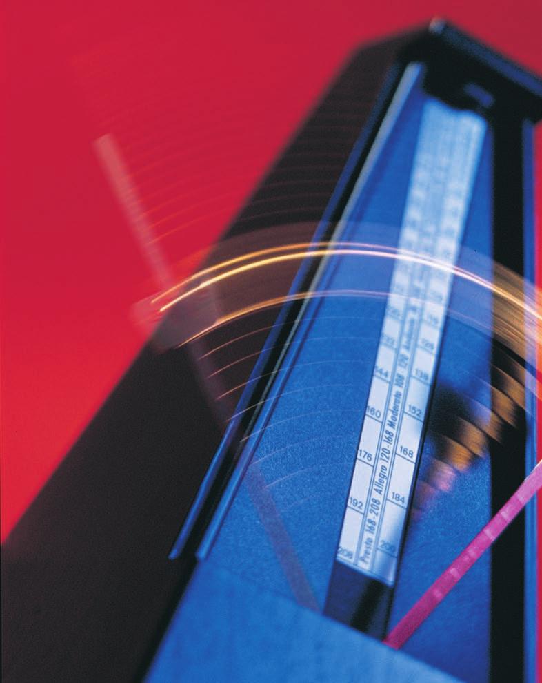
3 CHAPTER 11 Vibrations and Waves o A mechanical metronome consists of an inverted pendulum and a counterweight on opposite sides of a pivot. A sliding weight above the pivot is used to change the rate of vibration. As the pendulum vibrates, the metronome ticks, and musicians use the sound to keep a steady tempo. This vibration is an example of a periodic motion. WHAT TO EXPECT In this chapter, you will study a kind of periodic motion called simple harmonic motion and will learn about the relationship between simple harmonic vibrations and waves. WHY IT MATTERS Waves can carry information, such as conversations and television broadcasts. Much of your perception of the physical world is dependent on waves. You could not hear or see anything without sound waves and light waves. CHAPTER PREVIEW 1 Simple Harmonic Motion Hooke s Law The Simple Pendulum 2 Measuring Simple Harmonic Motion Amplitude, Period, and Frequency 3 Properties of Waves Wave Motion Wave Types Period, Frequency, and Wave Speed 4 Wave Interactions Wave Interference Reflection Standing Waves 367
4 SECTION 1 Simple Harmonic Motion SECTION OBJECTIVES Identify the conditions of simple harmonic motion. Explain how force, velocity, and acceleration change as an object vibrates with simple harmonic motion. Calculate the spring force using Hooke s law. HOOKE S LAW A repeated motion, such as that of an acrobat swinging on a trapeze, is called a periodic motion. Other periodic motions include those made by a child on a playground swing, a wrecking ball swaying to and fro, and the pendulum of a grandfather clock or a metronome. In each of these cases, the periodic motion is back and forth over the same path. One of the simplest types of back-and-forth periodic motion is the motion of a mass attached to a spring, as shown in Figure 1. Let us assume that the mass moves on a frictionless horizontal surface. When the spring is stretched or compressed and then released, it vibrates back and forth about its unstretched position. We will begin by considering this example, and then we will apply our conclusions to the swinging motion of a trapeze acrobat. (a) Maximum displacement (b) Equilibrium (c) Maximum displacement F elastic x F elastic x F elastic = 0 x = 0 Figure 1 The direction of the force acting on the mass (F elastic ) is always opposite the direction of the mass s displacement from equilibrium (x = 0). (a) When the spring is stretched to the right, the spring force pulls the mass to the left. (b) When the spring is unstretched, the spring force is zero. (c) When the spring is compressed to the left, the spring force is directed to the right. At the equilibrium position, speed reaches a maximum In Figure 1(a), the spring is stretched away from its unstretched, or equilibrium, position (x = 0). In this stretched position, the spring exerts a force on the mass toward the equilibrium position. This spring force decreases as the spring moves toward the equilibrium position, and it reaches zero at equilibrium, as illustrated in Figure 1(b). The mass s acceleration also becomes zero at equilibrium. Though the spring force and acceleration decrease as the mass moves toward the equilibrium position, the speed of the mass increases. At the equilibrium position, when acceleration reaches zero, the speed reaches a maximum. At that point, although the spring force is zero, the mass s momentum causes it to overshoot the equilibrium position and compress the spring. At maximum displacement, spring force and acceleration reach a maximum As the mass moves beyond equilibrium, the spring force and the acceleration increase. But the direction of the spring force and of the acceleration (toward equilibrium) is opposite the mass s direction of motion (away from equilibrium), and the mass begins to slow down. 368 Chapter 11

5 When the spring s compression is equal to the distance the spring was originally stretched away from the equilibrium position (x), as shown in Figure 1(c), the mass is at maximum displacement, and the spring force and acceleration of the mass reach a maximum. At this point, the speed of the mass becomes zero. The spring force acting to the right causes the mass to change its direction, and the mass begins moving back toward the equilibrium position. Then the entire process begins again, and the mass continues to oscillate back and forth over the same path. In an ideal system, the mass-spring system would oscillate indefinitely. But in the physical world, friction retards the motion of the vibrating mass, and the mass-spring system eventually comes to rest. This effect is called damping. In most cases, the effect of damping is minimal over a short period of time, so the ideal mass-spring system provides an approximation for the motion of a physical mass-spring system. Developed and maintained by the National Science Teachers Association For a variety of links related to this chapter, go to Topic: Hooke s Law SciLinks Code: HF60756 simple harmonic motion vibration about an equilibrium position in which a restoring force is proportional to the displacement from equilibrium In simple harmonic motion, restoring force is proportional to displacement As you have seen, the spring force always pushes or pulls the mass toward its original equilibrium position. For this reason, it is sometimes called a restoring force. Measurements show that the restoring force is directly proportional to the displacement of the mass. This relationship was determined in 1678 by Robert Hooke and is known as Hooke s Law. The following equation mathematically describes Hooke s Law: HOOKE S LAW F elastic = kx spring force = (spring constant displacement) The negative sign in the equation signifies that the direction of the spring force is always opposite the direction of the mass s displacement from equilibrium. In other words, the negative sign shows that the spring force will tend to move the object back to its equilibrium position. As mentioned in the chapter Work and Energy, the quantity k is a positive constant called the spring constant. The value of the spring constant is a measure of the stiffness of the spring. A greater value of k means a stiffer spring because a greater force is needed to stretch or compress that spring a given amount. The SI units of k are N/m. As a result, N is the unit of the spring force when the spring constant (N/m) is multiplied by the displacement (m). The motion of a vibrating mass-spring system is an example of simple harmonic motion. Simple harmonic motion describes any periodic motion that is the result of a restoring force that is proportional to displacement. Because simple harmonic motion involves a restoring force, every simple harmonic motion is a back-and-forth motion over the same path. 1. Earth s Orbit The motion of Earth orbiting the sun is periodic.is this motion simple harmonic? Why or why not? 2. Pinball In pinball games, the force exerted by a compressed spring is used to release a ball. If the distance the spring is compressed is doubled, how will the force exerted on the ball change? If the spring is replaced with one that is half as stiff, how will the force acting on the ball change? Vibrations and Waves 369
6 SAMPLE PROBLEM A Hooke s Law PROBLEM SOLUTION 1. DEFINE If a mass of 0.55 kg attached to a vertical spring stretches the spring 2.0 cm from its original equilibrium position, what is the spring constant? Given: m = 0.55 kg x = 2.0 cm = m g = 9.81 m/s 2 Unknown: k =? m +x x = 0 x = 2.0 cm Diagram: F elastic F g 2. PLAN Choose an equation or situation: When the mass is attached to the spring, the equilibrium position changes. At the new equilibrium position, the net force acting on the mass is zero. So the spring force (given by Hooke s law) must be equal and opposite to the weight of the mass. F net = 0 = F elastic + F g F elastic = kx F g = mg kx mg = 0 Rearrange the equation to isolate the unknown: kx = mg k = m g x 3. CALCULATE Substitute the values into the equation and solve: k = (0.55 kg)(9.81 m/s 2 ) m k = 270 N/m CALCULATOR SOLUTION The calculator answer for k is This answer is rounded to two significant figures, 270 N/m. 4. EVALUATE The value of k implies that 270 N of force is required to displace the spring 1 m. 370 Chapter 11

7 PRACTICE A Hooke s Law 1. Suppose the spring in Sample Problem A is replaced with a spring that stretches 36 cm from its equilibrium position. a. What is the spring constant in this case? b. Is this spring stiffer or less stiff than the one in Sample Problem A? 2. A load of 45 N attached to a spring that is hanging vertically stretches the spring 0.14 m. What is the spring constant? 3. A slingshot consists of a light leather cup attached between two rubber bands. If it takes a force of 32 N to stretch the bands 1.2 cm, what is the equivalent spring constant of the two rubber bands? 4. How much force is required to pull a spring 3.0 cm from its equilibrium position if the spring constant is N/m? A stretched or compressed spring has elastic potential energy As you saw in the chapter Work and Energy, a stretched or compressed spring stores elastic potential energy. To see how mechanical energy is conserved in an ideal mass-spring system, consider an archer shooting an arrow from a bow, as shown in Figure 2. Bending the bow by pulling back the bowstring is analogous to stretching a spring. To simplify this situation, we will disregard friction and internal energy. Once the bowstring has been pulled back, the bow stores elastic potential energy. Because the bow, arrow, and bowstring (the system) are now at rest, the kinetic energy of the system is zero, and the mechanical energy of the system is solely elastic potential energy. When the bowstring is released, the bow s elastic potential energy is converted to the kinetic energy of the arrow. At the moment the arrow leaves the bowstring, it gains most of the elastic potential energy originally stored in the bow. (The rest of the elastic potential energy is converted to the kinetic energy of the bow and the bowstring.) Thus, once the arrow leaves the bowstring, the mechanical energy of the bow-and-arrow system is solely kinetic. Because mechanical energy must be conserved, the total kinetic energy of the bow, arrow, and bowstring is equal to the elastic potential energy originally stored in the bow. PHYSICS Module 11 Hooke s Law provides an interactive lesson with guided problem-solving practice to teach you about springs and spring constants. Figure 2 The elastic potential energy stored in this stretched bow is converted into the kinetic energy of the arrow. Vibrations and Waves 371
, a driver needs all the wheels on the ground. Bumps in the road lift the wheels off the ground and rob the driver of control.")


8 THE INSIDE STORY ON SHOCK ABSORBERS Bumps in the road are certainly a nuisance, but without strategic use of damping devices, they could also prove deadly. To control a car going 110 km/h (70 mi/h), a driver needs all the wheels on the ground. Bumps in the road lift the wheels off the ground and rob the driver of control. A good solution is to fit the car with springs at each wheel. The springs absorb energy as the wheels rise over the bumps and push the wheels back to the pavement to keep the wheels on the road. However, once set in motion, springs tend to continue to go up and down in simple harmonic motion. This affects the driver s control of the car and can also be uncomfortable. One way to cut down on unwanted vibrations is to use stiff springs that compress only a few centimeters under thousands of newtons of force. Such springs have very high spring constants and thus do not vibrate as freely as softer springs with lower constants. However, this solution reduces the driver s ability to keep the car s wheels on the road. To completely solve the problem, energy-absorbing devices known as shock absorbers are placed parallel to the springs in some automobiles, as shown in part (a) of the illustration below. Shock absorbers are fluid-filled tubes that turn the simple harmonic motion of the springs into damped harmonic motion. In damped harmonic motion, each cycle of stretch and compression of the spring is much smaller than the previous cycle. Modern auto suspensions are set up so that all of a spring s energy is absorbed by the shock absorbers, eliminating vibrations in just one up-and-down cycle. This keeps the car from continually bouncing without sacrificing the spring s ability to keep the wheels on the road. Different spring constants and shock absorber damping are combined to give a wide variety of road responses. For example, larger vehicles have heavy-duty leaf springs made of stacks of steel strips, which have a larger spring constant than coil springs do. In this type of suspension system, the shock absorber is perpendicular to the spring, as shown in part (b) of the illustration. The stiffness of the spring can affect steering response time, traction, and the general feel of the car. As a result of the variety of combinations that are possible, your driving experiences can range from the luxurious floating of a limousine to the bone-rattling road feel of a sports car. (a) Coil spring Shock absorber (b) Shock absorber Leaf spring 372 Chapter 11

9 THE SIMPLE PENDULUM As you have seen, the periodic motion of a mass-spring system is one example of simple harmonic motion. Now consider the trapeze acrobats shown in Figure 3(a). Like the vibrating mass-spring system, the swinging motion of a trapeze acrobat is a periodic vibration. Is a trapeze acrobat s motion an example of simple harmonic motion? To answer this question, we will use a simple pendulum as a model of the acrobat s motion, which is a physical pendulum. A simple pendulum consists (a) of a mass called a bob, which is attached to a fixed string, as shown in Figure 3(b). When working with a simple pendulum, we assume that the mass of the bob is concentrated at a point and that the mass of the string is negligible. Furthermore, we disregard the effects of friction and air resistance. For a physical pendulum, on the other hand, the distribution of the mass must be considered, and friction and air resistance also must be taken into account. To simplify our analysis, we will disregard these complications and use a simple pendulum to approximate a physical pendulum in all of our examples. θ (b) Figure 3 (a) The motion of these trapeze acrobats is modeled by (b) a simple pendulum. The restoring force of a pendulum is a component of the bob s weight To see whether the pendulum s motion is simple harmonic, we must first examine the forces exerted on the pendulum s bob to determine which force acts as the restoring force. If the restoring force is proportional to the displacement, then the pendulum s motion is simple harmonic. Let us select a coordinate system in which the x-axis is tangent to the direction of motion and the y-axis is perpendicular to the direction of motion. Because the bob is always changing its position, these axes will change at each point of the bob s motion. The forces acting on the bob at any point include the force exerted by the string and the gravitational force. The force exerted by the string always acts along the y-axis, which is along the string. The gravitational force can be resolved into two components along the chosen axes, as shown in Figure 4. Because both the force exerted by the string and the y component of the gravitational force are perpendicular to the bob s motion, the x component of the gravitational force is the net force acting on the bob in the direction of its motion. In this case, the x component of the gravitational force always pulls the bob toward its equilibrium position and hence is the restoring force. Note that the restoring force (F g,x = F g sinq) is zero at equilibrium because q equals zero at this point. F g,x F T F g θ F g,y Figure 4 At any displacement from equilibrium, the weight of the bob (F g ) can be resolved into two components. The x component (F g,x ), which is perpendicular to the string, is the only force acting on the bob in the direction of its motion. Vibrations and Waves 373
10 Developed and maintained by the National Science Teachers Association For a variety of links related to this chapter, go to Topic: Pendulums SciLinks Code: HF61121 Energy of a Pendulum MATERIALS LIST pendulum bob and string tape toy car protractor meterstick or tape measure Tie one end of a piece of string around the pendulum bob, and use tape to secure it in place. Set the toy car on a smooth surface, and hold the string of the pendulum directly above the car so that the bob rests on the car. Use your other hand to pull back the bob of the pendulum, and have your partner measure the angle of the pendulum with the protractor. Release the pendulum so that the bob strikes the car. Measure the displacement of the car. What happened to the pendulum s potential energy after you released the bob? Repeat the process using different angles. How can you account for your results? For small angles, the pendulum s motion is simple harmonic As with a mass-spring system, the restoring force of a simple pendulum is not constant. Instead, the magnitude of the restoring force varies with the bob s distance from the equilibrium position. The magnitude of the restoring force is proportional to sinq. When the maximum angle of displacement q is relatively small (<15 ), sinq is approximately equal to q in radians. As a result, the restoring force is very nearly proportional to the displacement and the pendulum s motion is an excellent approximation of simple harmonic motion. We will assume small angles of displacement unless otherwise noted. Because a simple pendulum vibrates with simple harmonic motion, many of our earlier conclusions for a mass-spring system apply here. At maximum displacement, the restoring force and acceleration reach a maximum while the speed becomes zero. Conversely, at equilibrium, the restoring force and acceleration become zero and speed reaches a maximum. Table 1 on the following page illustrates the analogy between a simple pendulum and a mass-spring system. Gravitational potential increases as a pendulum s displacement increases As with the mass-spring system, the mechanical energy of a simple pendulum is conserved in an ideal (frictionless) system. However, the spring s potential energy is elastic, while the pendulum s potential energy is gravitational. We define the gravitational potential energy of a pendulum to be zero when it is at the lowest point of its swing. Figure 5 illustrates how a pendulum s mechanical energy changes as the pendulum oscillates. At maximum displacement from equilibrium, a pendulum s energy is entirely gravitational potential energy. As the pendulum swings toward equilibrium, it gains kinetic energy and loses potential energy. At the equilibrium position, its energy becomes solely kinetic. As the pendulum swings past its equilibrium position, the kinetic energy decreases while the gravitational potential energy increases. At maximum displacement from equilibrium, the pendulum s energy is once again entirely gravitational potential energy. Energy (a) Displacement (b) (c) Figure 5 Whether at maximum displacement (a), equilibrium (b), or maximum displacement in the other direction (c), the pendulum s total mechanical energy remains the same. However, as the graph shows, the pendulum s kinetic energy and potential energy are constantly changing. Total mechanical energy Potential energy Kinetic energy 374 Chapter 11
11 Table 1 Simple Harmonic Motion maximum displacement θ m F x = F max a = a max v = 0 equilibrium m F x = 0 a = 0 v = v max maximum displacement F x = F max θ m a = a max v = 0 equilibrium m F x = 0 a = 0 v = v max maximum displacement F x = F max θ x 0 m + x a = a max v = 0 SECTION REVIEW 1. Which of these periodic motions are simple harmonic? a. a child swinging on a playground swing (q = 45 ) b. a CD rotating in a player c. an oscillating clock pendulum (q = 10 ) 2. A pinball machine uses a spring that is compressed 4.0 cm to launch a ball. If the spring constant is 13 N/m, what is the force on the ball at the moment the spring is released? 3. How does the restoring force acting on a pendulum bob change as the bob swings toward the equilibrium position? How do the bob s acceleration (along the direction of motion) and velocity change? 4. Critical Thinking When an acrobat reaches the equilibrium position, the net force acting along the direction of motion is zero. Why does the acrobat swing past the equilibrium position? Vibrations and Waves 375

12 SECTION 2 SECTION OBJECTIVES Identify the amplitude of vibration. Recognize the relationship between period and frequency. Calculate the period and frequency of an object vibrating with simple harmonic motion. amplitude the maximum displacement from equilibrium period the time that it takes a complete cycle to occur frequency the number of cycles or vibrations per unit of time Measuring Simple Harmonic Motion AMPLITUDE, PERIOD, AND FREQUENCY In the absence of friction, a moving trapeze always returns to the same maximum displacement after each swing. This maximum displacement from the equilibrium position is the amplitude. A pendulum s amplitude can be measured by the angle between the pendulum s equilibrium position and its maximum displacement. For a mass-spring system, the amplitude is the maximum amount the spring is stretched or compressed from its equilibrium position. Period and frequency measure time Imagine the ride shown in Figure 6 swinging from maximum displacement on one side of equilibrium to maximum displacement on the other side, and then back again. This cycle is considered one complete cycle of motion. The period, T, is the time it takes for this complete cycle of motion. For example, if one complete cycle takes 20 s, then the period of this motion is 20 s. Note that after the time T, the object is back where it started. The number of complete cycles the ride swings through in a unit of time is the ride s frequency, f. If one complete cycle takes 20 s, then the ride s frequency is 2 1 cycles/s, or 0.05 cycles/s. The SI unit of frequency is s 1, known as 0 hertz (Hz). In this case, the ride s frequency is 0.05 Hz. Period and frequency can be confusing because both are concepts involving time in simple harmonic motion. Notice that the period is the time per cycle and that the frequency is the number of cycles per unit time, so they are inversely related. f = T 1 or T = 1 f This relationship was used to determine the frequency of the ride. 1 1 f = = 20 = 0.05 Hz T s In any problem where you have a value for period or frequency, you can calculate the other value. These terms are summarized in Table 2 on the next page. Figure 6 For any periodic motion such as the motion of this amusement park ride in Helsinki, Finland period and frequency are inversely related.
13 Table 2 Measures of Simple Harmonic Motion Term Example Definition SI unit amplitude maximum displacement radian, rad from equilibrium meter, m θ Integrating Technology Visit go.hrw.com for the activity Bicycle Design and Shock Absorption. Keyword HF6VIBX period, T time that it takes second, s to complete a full cycle frequency, f number of cycles or hertz, Hz vibrations per (Hz = s 1 ) unit of time The period of a simple pendulum depends on pendulum length and free-fall acceleration Although both a simple pendulum and a mass-spring system vibrate with simple harmonic motion, calculating the period and frequency of each requires a separate equation. This is because in each, the period and frequency depend on different physical factors. Consider an experimental setup of two pendulums of the same length but with bobs of different masses. The length of a pendulum is measured from the pivot point to the center of mass of the pendulum bob. If you were to pull each bob aside the same small distance and then release them at the same time, each pendulum would complete one vibration in the same amount of time. If you then changed the amplitude of one of the pendulums, you would find that they would still have the same period. Thus, for small amplitudes, the period of a pendulum does not depend on the mass or on the amplitude. However, changing the length of a pendulum does affect its period. A change in the free-fall acceleration also affects the period of a pendulum. The exact relationship between these variables can be derived mathematically or found experimentally. PERIOD OF A SIMPLE PENDULUM IN SIMPLE HARMONIC MOTION T = 2p L ag period = 2p square root of (length divided by free-fall acceleration) Did you know? Galileo is credited as the first person to notice that the motion of a pendulum depends on its length and is independent of its amplitude (for small angles). He supposedly observed this while attending church services at a cathedral in Pisa. The pendulum he studied was a swinging chandelier that was set in motion when someone bumped it while lighting the candles. Galileo is said to have measured its frequency, and hence its period, by timing the swings with his pulse. Vibrations and Waves 377
14 θ θ L 2 L 1 m m Figure 7 When the length of one pendulum is decreased, the distance that the pendulum travels to equilibrium is also decreased. Because the accelerations of the two pendulums are equal, the shorter pendulum will have a smaller period. Why does the period of a pendulum depend on pendulum length and freefall acceleration? When two pendulums have different lengths but the same amplitude, the shorter pendulum will have a smaller arc to travel through, as shown in Figure 7. Because the distance from maximum displacement to equilibrium is less while the acceleration caused by the restoring force remains the same, the shorter pendulum will have a shorter period. Why don t mass and amplitude affect the period of a pendulum? When the bobs of two pendulums differ in mass, the heavier mass provides a larger restoring force, but it also needs a larger force to achieve the same acceleration. This is similar to the situation for objects in free fall, which all have the same acceleration regardless of their mass. Because the acceleration of both pendulums is the same, the period for both is also the same. For small angles (<15 ), when the amplitude of a pendulum increases, the restoring force also increases proportionally. Because force is proportional to acceleration, the initial acceleration will be greater. However, the distance this pendulum must cover is also greater. For small angles, the effects of the two increasing quantities cancel and the pendulum s period remains the same. SAMPLE PROBLEM B Simple Harmonic Motion of a Simple Pendulum PROBLEM SOLUTION You need to know the height of a tower, but darkness obscures the ceiling. You note that a pendulum extending from the ceiling almost touches the floor and that its period is 12 s. How tall is the tower? Given: T = 12 s a g = g = 9.81 m/s 2 Unknown: L =? Use the equation for the period of a simple pendulum, and solve for L. T = 2p L ag T a g = L 2p 2 T a g 2 = L 4p L = (12 s)2 ( 9.81 m/s 2 ) 4p 2 Remember that on Earth s surface, a g = g = 9.81 m/s 2. Use this value in the equation for the period of a pendulum if a problem does not specify otherwise. At higher altitudes or on different planets, use the given value of a g instead. L = 36 m 378 Chapter 11

15 PRACTICE B Simple Harmonic Motion of a Simple Pendulum 1. If the period of the pendulum in the preceding sample problem were 24 s, how tall would the tower be? 2. You are designing a pendulum clock to have a period of 1.0 s. How long should the pendulum be? 3. A trapeze artist swings in simple harmonic motion with a period of 3.8 s. Calculate the length of the cables supporting the trapeze. 4. Calculate the period and frequency of a m long pendulum at the following locations: a. the North Pole, where a g = m/s 2 b. Chicago, where a g = m/s 2 c. Jakarta, Indonesia, where a g = m/s 2 Period of a mass-spring system depends on mass and spring constant Now consider the period of a mass-spring system. In this case, according to Hooke s law, the restoring force acting on the mass is determined by the displacement of the mass and by the spring constant (F elastic = kx). The magnitude of the mass does not affect the restoring force. So, unlike in the case of the pendulum, in which a heavier mass increased both the force on the bob and the bob s inertia, a heavier mass attached to a spring increases inertia without providing a compensating increase in force. Because of this increase in inertia, a heavy mass has a smaller acceleration than a light mass has. Thus, a heavy mass will take more time to complete one cycle of motion. In other words, the heavy mass has a greater period. Thus, as mass increases, the period of vibration increases when there is no compensating increase in force. 1. Pendulum on the Moon The free-fall acceleration on the surface of the moon is approximately one-sixth of the free-fall acceleration on the surface of Earth. Compare the period of a pendulum on the moon with that of an identical pendulum set in motion on Earth. 2. Pendulum Clocks Why is a wound mainspring often used to provide energy to a pendulum clock in order to prevent the amplitude of the pendulum from decreasing?
16 The greater the spring constant (k), the stiffer the spring; hence a greater force is required to stretch or compress the spring. When force is greater, acceleration is greater and the amount of time required for a single cycle should decrease (assuming that the amplitude remains constant). Thus, for a given amplitude, a stiffer spring will take less time to complete one cycle of motion than one that is less stiff. As with the pendulum, the equation for the period of a mass-spring system can be derived mathematically or found experimentally. PERIOD OF A MASS-SPRING SYSTEM IN SIMPLE HARMONIC MOTION T = 2p m k period = 2p square root of (mass divided by spring constant) Note that changing the amplitude of the vibration does not affect the period. This statement is true only for systems and circumstances in which the spring obeys Hooke s law. SAMPLE PROBLEM C Simple Harmonic Motion of a Mass-Spring System PROBLEM SOLUTION The body of a 1275 kg car is supported on a frame by four springs. Two people riding in the car have a combined mass of 153 kg. When driven over a pothole in the road, the frame vibrates with a period of s. For the first few seconds, the vibration approximates simple harmonic motion. Find the spring constant of a single spring. Given: m = (1275 kg kg) = 357 kg 4 Unknown: k =? T = s Use the equation for the period of a mass-spring system, and solve for k. T = 2p m k T 2 =4p 2 m k 4p 2 m k = = T 2 4p 2 (357 kg) (0.840 s) 2 k = N/m 380 Chapter 11
17 PRACTICE C Simple Harmonic Motion of a Mass-Spring System 1. A mass of 0.30 kg is attached to a spring and is set into vibration with a period of 0.24 s. What is the spring constant of the spring? 2. When a mass of 25 g is attached to a certain spring, it makes 20 complete vibrations in 4.0 s. What is the spring constant of the spring? 3. A 125 N object vibrates with a period of 3.56 s when hanging from a spring. What is the spring constant of the spring? 4. When two more people get into the car described in Sample Problem C, the total mass of all four occupants of the car becomes 255 kg. Now what is the period of vibration of the car when it is driven over a pothole in the road? 5. A spring of spring constant 30.0 N/m is attached to different masses, and the system is set in motion. Find the period and frequency of vibration for masses of the following magnitudes: a. 2.3 kg b. 15 g c. 1.9 kg SECTION REVIEW 1. The reading on a metronome indicates the number of oscillations per minute. What are the frequency and period of the metronome s vibration when the metronome is set at 180? 2. A child swings on a playground swing with a 2.5 m long chain. a. What is the period of the child s motion? b. What is the frequency of vibration? 3. A 0.75 kg mass attached to a vertical spring stretches the spring 0.30 m. a. What is the spring constant? b. The mass-spring system is now placed on a horizontal surface and set vibrating. What is the period of the vibration? 4. Critical Thinking Two mass-spring systems vibrate with simple harmonic motion. If the spring constants are equal and the mass of one system is twice that of the other, which system has a greater period? Vibrations and Waves 381

18 SECTION 3 Properties of Waves SECTION OBJECTIVES Distinguish local particle vibrations from overall wave motion. Differentiate between pulse waves and periodic waves. Interpret waveforms of transverse and longitudinal waves. Apply the relationship among wave speed, frequency, and wavelength to solve problems. Relate energy and amplitude. WAVE MOTION Consider what happens to the surface of a pond when you drop a pebble into the water. The disturbance created by the pebble generates water waves that travel away from the disturbance, as seen in Figure 8. If you examined the motion of a leaf floating near the disturbance, you would see that the leaf moves up and down and back and forth about its original position. However, the leaf does not undergo any net displacement from the motion of the waves. The leaf s motion indicates the motion of the particles in the water. The water molecules move locally, like the leaf does, but they do not travel across the pond. That is, the water wave moves from one place to another, but the water itself is not carried with it. Figure 8 A pebble dropped into a pond creates ripple waves similar to those shown here. medium a physical environment through which a disturbance can travel mechanical wave a wave that requires a medium through which to travel A wave is the motion of a disturbance Ripple waves in a pond start with a disturbance at some point in the water. This disturbance causes water on the surface near that point to move, which in turn causes points farther away to move. In this way, the waves travel outward in a circular pattern away from the original disturbance. In this example, the water in the pond is the medium through which the disturbance travels. Particles in the medium in this case, water molecules move in vertical circles as waves pass. Note that the medium does not actually travel with the waves. After the waves have passed, the water returns to its original position. Waves of almost every kind require a material medium in which to travel. Sound waves, for example, cannot travel through outer space, because space is very nearly a vacuum. In order for sound waves to travel, they must have a medium such as air or water. Waves that require a material medium are called mechanical waves. Not all wave propagation requires a medium. Electromagnetic waves, such as visible light, radio waves, microwaves, and X rays, can travel through a vacuum. You will study electromagnetic waves in later chapters. 382 Chapter 11

19 WAVE TYPES One of the simplest ways to demonstrate wave motion is to flip one end of a taut rope whose opposite end is fixed, as shown in Figure 9. The flip of your wrist creates a pulse that travels to the fixed end with a definite speed. A wave that consists of a single traveling pulse is called a pulse wave. Figure 9 A single flip of the wrist creates a pulse wave on a taut rope. Now imagine that you continue to generate pulses at one end of the rope. Together, these pulses form what is called a periodic wave. Whenever the source of a wave s motion is a periodic motion, such as the motion of your hand moving up and down repeatedly, a periodic wave is produced. Sine waves describe particles vibrating with simple harmonic motion Figure 10 depicts a blade that vibrates with simple harmonic motion and thus makes a periodic wave on a string. As the wave travels to the right, any single point on the string vibrates up and down. Because the blade is vibrating with simple harmonic motion, the vibration of each point of the string is also simple harmonic. A wave whose source vibrates with simple harmonic motion is called a sine wave. Thus, a sine wave is a special case of a periodic wave in which the periodic motion is simple harmonic. The wave in Figure 10 is called a sine wave because a graph of the trigonometric function y = sin x produces this curve when plotted. A close look at a single point on the string illustrated in Figure 10 shows that its motion resembles the motion of a mass hanging from a vibrating spring. As the wave travels to the right, the point vibrates around its equilibrium position with simple harmonic motion. This relationship between simple harmonic motion and wave motion enables us to use some of the terms and concepts from simple harmonic motion in our study of wave motion. Developed and maintained by the National Science Teachers Association For a variety of links related to this chapter, go to Topic: Wave Motion SciLinks Code: HF61639 (a) Vibrating blade (c) (b) (d) Figure 10 As the sine wave created by this vibrating blade travels to the right, a single point on the string vibrates up and down with simple harmonic motion. Vibrations and Waves 383
20 transverse wave a wave whose particles vibrate perpendicularly to the direction the wave is traveling crest the highest point above the equilibrium position trough the lowest point below the equilibrium position wavelength the distance between two adjacent similar points of a wave, such as from crest to crest or from trough to trough Vibrations of a transverse wave are perpendicular to the wave motion Figure 11(a) is a representation of the wave shown in Figure 10 (on the previous page) at a specific instant of time, t. This wave travels to the right as the particles of the rope vibrate up and down. Thus, the vibrations are perpendicular to the direction of the wave s motion. A wave such as this, in which the particles of the disturbed medium move perpendicularly to the wave motion, is called a transverse wave. The wave shown in Figure 11(a) can be represented on a coordinate system, as shown in Figure 11(b). A picture of a wave like the one in Figure 11(b) is sometimes called a waveform. A waveform can represent either the displacements of each point of the wave at a single moment in time or the displacements of a single particle as time passes. In this case, the waveform depicts the displacements at a single instant. The x-axis represents the equilibrium position of the string, and the y coordinates of the curve represent the displacement of each point of the string at time t. For example, points where the curve crosses the x-axis (where y = 0) have zero displacement. Conversely, at the highest and lowest points of the curve, where displacement is greatest, the absolute values of y are greatest. Wave measures include crest, trough, amplitude, and wavelength A wave can be measured in terms of its displacement from equilibrium. The highest point above the equilibrium position is called the wave crest. The lowest point below the equilibrium position is the trough of the wave. As in simple harmonic motion, amplitude is a measure of maximum displacement from equilibrium. The amplitude of a wave is the distance from the equilibrium position to a crest or to a trough, as shown in Figure 11(b). As a wave passes a given point along its path, that point undergoes cyclical motion. The point is displaced first in one direction and then in the other direction. Finally, the point returns to its original equilibrium position, thereby completing one cycle. The distance the wave travels along its path during one cycle is called the wavelength, l (the Greek letter lambda). A simple way to find the wavelength is to measure the distance between two adjacent similar points of the wave, such as from crest to crest or from trough to trough. Notice in Figure 11(b) that the distances between adjacent crests or troughs in the waveform are equal. Figure 11 (a) A picture of a transverse wave at some instant t can be turned into (b) a graph. The x-axis represents the equilibrium position of the string. The curve shows the displacements of the string at time t. (a) Displacement (b) y Trough λ λ Crest x Amplitude λ = Wavelength 384 Chapter 11
21 Vibrations of a longitudinal wave are parallel to the wave motion You can create another type of wave with a spring. Suppose that one end of the spring is fixed and that the free end is pumped back and forth along the length of the spring, as shown in Figure 12. This action produces compressed and stretched regions of the coil that travel along the spring. The displacement of the coils is in the direction of wave motion. In other words, the vibrations are parallel to the motion of the wave. Compressed Stretched Compressed Stretched When the particles of the medium vibrate parallel to the direction of wave motion, the wave is called a longitudinal wave. Sound waves in the air are longitudinal waves because air particles vibrate back and forth in a direction parallel to the direction of wave motion. A longitudinal wave can also be described by a sine curve. Consider a longitudinal wave traveling on a spring. Figure 13(a) is a snapshot of the longitudinal wave at some instant t, and Figure 13(b) shows the sine curve representing the wave. The compressed regions correspond to the crests of the waveform, and the stretched regions correspond to troughs. The type of wave represented by the curve in Figure 13(b) is often called a density wave or a pressure wave. The crests, where the spring coils are compressed, are regions of high density and pressure (relative to the equilibrium density or pressure of the medium). Conversely, the troughs, where the coils are stretched, are regions of low density and pressure. Figure 12 As this wave travels to the right, the coils of the spring are tighter in some regions and looser in others. The displacement of the coils is parallel to the direction of wave motion, so this wave is longitudinal. longitudinal wave a wave whose particles vibrate parallel to the direction the wave is traveling (a) Density x 1 x 2 x 3 x 4 (b) x 1 x 2 x 3 x 4 y x Figure 13 (a) A longitudinal wave at some instant t can also be represented by (b) a graph. The crests of this waveform correspond to compressed regions, and the troughs correspond to stretched regions. PERIOD, FREQUENCY, AND WAVE SPEED Sound waves may begin with the vibrations of your vocal cords, a guitar string, or a taut drumhead. In each of these cases, the source of wave motion is a vibrating object. The vibrating object that causes a sine wave always has a characteristic frequency. Because this motion is transferred to the particles of the medium, the frequency of vibration of the particles is equal to the frequency of the source. When the vibrating particles of the medium complete one full cycle, one complete wavelength passes any given point. Thus, wave frequency describes the number of waves that pass a given point in a unit of time. Vibrations and Waves 385
22 The period of a wave is the time required for one complete cycle of vibration of the medium s particles. As the particles of the medium complete one full cycle of vibration at any point of the wave, one wavelength passes by that point. Thus, the period of a wave describes the time it takes for a complete wavelength to pass a given point. The relationship between period and frequency seen earlier in this chapter holds true for waves as well; the period of a wave is inversely related to its frequency. Did you know? The frequencies of sound waves that are audible to humans range from 20 Hz to Hz. Electromagnetic waves, which include visible light, radio waves, and microwaves, have an even broader range of frequencies from about 10 4 Hz and lower to Hz and higher. Wave speed equals frequency times wavelength We can now derive an expression for the speed of a wave in terms of its period or frequency. We know that speed is equal to displacement divided by the time it takes to undergo that displacement. v = x t For waves, a displacement of one wavelength (l) occurs in a time interval equal to one period of the vibration (T ). v = T l As you saw earlier in this chapter, frequency and period are inversely related. f = T 1 Substituting this frequency relationship into the previous equation for speed gives a new equation for the speed of a wave. PHYSICS Module 12 Frequency and Wavelength provides an interactive lesson with guided problemsolving practice to teach you about wave properties and the wave-speed equation. SPEED OF A WAVE l v = = fl T v = fl speed of a wave = frequency wavelength The speed of a mechanical wave is constant for any given medium. For example, at a concert, sound waves from different instruments reach your ears at the same moment, even when the frequencies of the sound waves are different. Thus, although the frequencies and wavelengths of the sounds produced by each instrument may be different, the product of the frequency and wavelength is always the same at the same temperature. As a result, when a mechanical wave s frequency is increased, its wavelength must decrease in order for its speed to remain constant. The speed of a wave changes only when the wave moves from one medium to another or when certain properties of the medium (such as temperature) are varied. 386 Chapter 11
23 SAMPLE PROBLEM D Wave Speed PROBLEM SOLUTION A piano string tuned to middle C vibrates with a frequency of 262 Hz. Assuming the speed of sound in air is 343 m/s, find the wavelength of the sound waves produced by the string. Given: v = 343 m/s f = 262 Hz Unknown: l =? Use the equation relating speed, wavelength, and frequency for a wave. v = f l v 343 m/ s l = = = m s f Hz 262s l = 1.31 m PRACTICE D Wave Speed 1. A piano emits frequencies that range from a low of about 28 Hz to a high of about 4200 Hz. Find the range of wavelengths in air attained by this instrument when the speed of sound in air is 340 m/s. 2. The speed of all electromagnetic waves in empty space is m/s. Calculate the wavelength of electromagnetic waves emitted at the following frequencies: a. radio waves at 88.0 MHz b. visible light at MHz c. X rays at MHz 3. The red light emitted by a He-Ne laser has a wavelength of 633 nm in air and travels at m/s. Find the frequency of the laser light. 4. A tuning fork produces a sound with a frequency of 256 Hz and a wavelength in air of 1.35 m. a. What value does this give for the speed of sound in air? b. What would be the wavelength of this same sound in water in which sound travels at 1500 m/s? Vibrations and Waves 387
24 Integrating Earth Science Visit go.hrw.com for the activity Earthquake Waves. Keyword HF6VIBX Waves transfer energy When a pebble is dropped into a pond, the water wave that is produced carries a certain amount of energy. As the wave spreads to other parts of the pond, the energy likewise moves across the pond. Thus, the wave transfers energy from one place in the pond to another while the water remains in essentially the same place. In other words, waves transfer energy by the vibration of matter rather than by the transfer of matter itself. For this reason, waves are often able to transport energy efficiently. The rate at which a wave transfers energy depends on the amplitude at which the particles of the medium are vibrating. The greater the amplitude, the more energy a wave carries in a given time interval. For a mechanical wave, the energy transferred is proportional to the square of the wave s amplitude. When the amplitude of a mechanical wave is doubled, the energy it carries in a given time interval increases by a factor of four. Conversely, when the amplitude is halved, the energy decreases by a factor of four. As with a mass-spring system or a simple pendulum, the amplitude of a wave gradually diminishes over time as its energy is dissipated. This effect, called damping, is usually minimal over relatively short distances. For simplicity, we have disregarded damping in our analysis of wave motions. SECTION REVIEW 1. As waves pass by a duck floating on a lake, the duck bobs up and down but remains in essentially one place. Explain why the duck is not carried along by the wave motion. 2. Sketch each of the following waves that are on a spring that is attached to a wall at one end: a. a pulse wave that is longitudinal b. a periodic wave that is longitudinal c. a pulse wave that is transverse d. a periodic wave that is transverse 3. Draw a graph for each of the waves described in items (b) and (d) above, and label the y-axis of each graph with the appropriate variable. Label the following on each graph: crest, trough, wavelength, and amplitude. 4. If the amplitude of a sound wave is increased by a factor of four, how does the energy carried by the sound wave in a given time interval change? 5. The smallest insects that a bat can detect are approximately the size of one wavelength of the sound the bat makes. What is the minimum frequency of sound waves required for the bat to detect an insect that is 0.57 cm long? (Assume the speed of sound is 340 m/s.) 388 Chapter 11


25 Wave Interactions SECTION 4 SECTION OBJECTIVES WAVE INTERFERENCE When two bumper boats collide, as shown in Figure 14, each bounces back in another direction. The two bumper boats cannot occupy the same space, and so they are forced to change the direction of their motion. This is true not just of bumper boats but of all matter. Two different material objects can never occupy the same space at the same time. Apply the superposition principle. Differentiate between constructive and destructive interference. Predict when a reflected wave will be inverted. Predict whether specific traveling waves will produce a standing wave. Identify nodes and antinodes of a standing wave. Figure 14 Two of these bumper boats cannot be in the same place at one time. Waves, on the other hand, can pass through one another. When two waves come together, they do not bounce back as bumper boats do. If you listen carefully at a concert, you can distinguish the sounds of different instruments. Trumpet sounds are different from flute sounds, even when the two instruments are played at the same time. The sound waves of each instrument are unaffected by the other waves that are passing through the same space at the same moment. Because mechanical waves are not matter but rather are displacements of matter, two waves can occupy the same space at the same time. The combination of two overlapping waves is called superposition. Figure 15 shows two sets of water waves in a ripple tank. As the waves move outward from their respective sources, they pass through one another. As they pass through one another, the waves interact to form an interference pattern of light and dark bands. Although this superposition of mechanical waves is fairly easy to observe, these are not the only kind of waves that can pass through the same space at the same time. Visible light and other forms of electromagnetic radiation also undergo superposition, and they can interact to form interference patterns. Figure 15 This ripple tank demonstrates the interference of water waves. Vibrations and Waves 389
26 Displacements in the same direction produce constructive interference In Figure 16(a), two wave pulses are traveling toward each other on a stretched rope. The larger pulse is moving to the right, while the smaller pulse moves toward the left. At the moment the two wave pulses meet, a resultant wave is formed, as shown in Figure 16(b). (a) (c) Figure 16 When these two wave pulses meet, the displacements at each point add up to form a resultant wave. This is an example of constructive interference. (b) (d) constructive interference a superposition of two or more waves in which individual displacements on the same side of the equilibrium position are added together to form the resultant wave At each point along the rope, the displacements due to the two pulses are added together, and the result is the displacement of the resultant wave. For example, when the two pulses exactly coincide, as they do in Figure 16(c), the amplitude of the resultant wave is equal to the sum of the amplitudes of each pulse. This method of summing the displacements of waves is known as the superposition principle. According to this principle, when two or more waves travel through a medium at the same time, the resultant wave is the sum of the displacements of the individual waves at each point. Ideally, the superposition principle holds true for all types of waves, both mechanical and electromagnetic. However, experiments show that in reality the superposition principle is valid only when the individual waves have small amplitudes an assumption we make in all our examples. Notice that after the two pulses pass through each other, each pulse has the same shape it had before the waves met and each is still traveling in the same direction, as shown in Figure 16(d). This is true for sound waves at a concert, water waves in a pond, light waves, and other types of waves. Each wave maintains its own characteristics after interference, just as the two pulses do in our example above. You have seen that when more than one wave travels through the same space at the same time, the resultant wave is equal to the sum of the individual displacements. If the displacements are on the same side of equilibrium, as in Figure 16, they have the same sign. When added together, the resultant wave is larger than the individual displacements. This is called constructive interference. 390 Chapter 11
27 Displacements in opposite directions produce destructive interference What happens if the pulses are on opposite sides of the equilibrium position, as they are in Figure 17(a)? In this case, the displacements have different signs, one positive and one negative. When the positive and negative displacements are added, as shown in Figure 17(b) and (c), the resultant wave is the difference between the pulses. This is called destructive interference. After the pulses separate, their shapes are unchanged, as seen in Figure 17(d). destructive interference a superposition of two or more waves in which individual displacements on opposite sides of the equilibrium position are added together to form the resultant wave (a) (c) (b) (d) Figure 17 In this case, known as destructive interference, the displacement of one pulse is subtracted from the displacement of the other. Figure 18 shows two pulses of equal amplitude but with displacements of opposite signs. When the two pulses coincide and the displacements are added, the resultant wave has a displacement of zero. In other words, at the instant the two pulses overlap, they completely cancel each other; it is as if there were no disturbance at all. This situation is known as complete destructive interference. If these waves were water waves coming together, one of the waves would be acting to pull an individual drop of water upward at the same instant and with the same force that another wave would be acting to pull it downward. The result would be no net force on the drop, and there would be no net displacement of the water at that moment. Thus far, we have considered the interference produced by two transverse pulse waves. The superposition principle is valid for longitudinal waves as well. In a compression, particles are moved closer together, while in a rarefaction, particles are spread farther apart. So, when a compression and a rarefaction interfere, there is destructive interference. In our examples, we have considered constructive and destructive interference separately, and we have dealt only with pulse waves. With periodic waves, complicated patterns arise that involve regions of constructive and destructive interference. The locations of these regions may remain fixed or may vary with time as the individual waves travel. Figure 18 The resultant displacement at each point of the string is zero, so the two pulses cancel one another. This is complete destructive interference. Vibrations and Waves 391
28 ADVANCED TOPICS See De Broglie Waves in Appendix J: Advanced Topics to learn about the wave characteristics that all matter exhibits at the microscopic level. REFLECTION In our discussion of waves so far, we have assumed that the waves being analyzed could travel indefinitely without striking anything that would stop them or otherwise change their motion. But what happens to the motion of a wave when it reaches a boundary? At a free boundary, waves are reflected Consider a pulse wave traveling on a stretched rope whose end forms a ring around a post, as shown in Figure 19(a). We will assume that the ring is free to slide along the post without friction. As the pulse travels to the right, each point of the rope moves up once and then back down. When the pulse reaches the boundary, the rope is free to move up as usual, and it pulls the ring up with it. Then, the ring is pulled back down by the tension in the rope. The movement of the rope at the post is similar to the movement that would result if someone were to whip the rope upward to send a pulse to the left, which would cause a pulse to travel back along the rope to the left. This is called reflection. Note that the reflected pulse is upright and has the same amplitude as the incident pulse. At a fixed boundary, waves are reflected and inverted Now consider a pulse traveling on a stretched rope that is fixed at one end, as in Figure 19(b). When the pulse reaches the wall, the rope exerts an upward force on the wall, and the wall in turn exerts an equal and opposite reaction force on the rope. This downward force on the rope causes a displacement in the direction opposite the displacement of the original pulse. As a result, the pulse is inverted after reflection. Incident pulse Incident pulse Figure 19 (a) When a pulse travels down a rope whose end is free to slide up the post, the pulse is reflected from the free end. (b) When a pulse travels down a rope that is fixed at one end, the reflected pulse is inverted. (a) Reflected pulse (b) Reflected pulse 392 Chapter 11


29 STANDING WAVES Consider a string that is attached on one end to a rigid support and that is shaken up and down in a regular motion at the other end. The regular motion produces waves of a certain frequency, wavelength, and amplitude traveling down the string. When the waves reach the other end, they are reflected back toward the oncoming waves. If the string is vibrated at exactly the right frequency, a standing wave a resultant wave pattern that appears to be stationary on the string is produced. The standing wave consists of alternating regions of constructive and destructive interference. Standing waves have nodes and antinodes Figure 20(a) shows four possible standing waves for a given string length. The points at which complete destructive interference happens are called nodes. There is no motion in the string at the nodes. But midway between two adjacent nodes, the string vibrates with the largest amplitude. These points are called antinodes. Figure 20(b) shows the oscillation of the second case shown in Figure 20(a) during half a cycle. All points on the string oscillate vertically with the same frequency, except for the nodes, which are stationary. In this case, there are three nodes (N ) and two antinodes (A), as illustrated in the figure. standing wave a wave pattern that results when two waves of the same frequency, wavelength, and amplitude travel in opposite directions and interfere node a point in a standing wave that maintains zero displacement antinode a point in a standing wave, halfway between two nodes, at which the largest displacement occurs N A N A N t = 0 t = 1 T 8 t = 1 T 4 3 t = T 8 t = 1 T 2 (b) (a) Figure 20 (a) This photograph shows four possible standing waves that can exist on a given string. (b) The diagram shows the progression of the second standing wave for one-half of a cycle. Vibrations and Waves 393
30 (a) (b) (c) (d) L Figure 21 Only certain frequencies produce standing waves on this fixed string. The wavelength of these standing waves depends on the string length. Possible wavelengths include 2L (b), L (c), and 2 3 L (d). Only certain frequencies, and therefore wavelengths, produce standing wave patterns. Figure 21 shows standing waves for a given string length. In each case, the curves represent the position of the string at different instants of time. If the string were vibrating rapidly, the several positions would blur together and give the appearance of loops, like those shown in the diagram. A single loop corresponds to either a crest or trough alone, while two loops correspond to a crest and a trough together, or one wavelength. The ends of the string must be nodes because these points cannot vibrate. As you can see in Figure 21, a standing wave can be produced for any wavelength that allows both ends of the string to be nodes. For example, in Figure 21(b), each end is a node, and there are no nodes in between. Because a single loop corresponds to either a crest or trough alone, this standing wave corresponds to one-half of a wavelength. Thus, the wavelength in this case is equal to twice the string length (2L). The next possible standing wave, shown in Figure 21(c), has three nodes: one at either end and one in the middle. In this case, there are two loops, which correspond to a crest and a trough. Thus, this standing wave has a wavelength equal to the string length (L). The next case, shown in Figure 21(d), has a wavelength equal to two-thirds of the string length 2 3 L, and the pattern continues. Wavelengths between the values shown here do not produce standing waves because they allow only one end of the string to be a node. SECTION REVIEW 1. A wave of amplitude 0.30 m interferes with a second wave of amplitude 0.20 m. What is the largest resultant displacement that may occur? 2. A string is rigidly attached to a post at one end. Several pulses of amplitude 0.15 m sent down the string are reflected at the post and travel back down the string without a loss of amplitude. What is the amplitude at a point on the string where the maximum displacement points of two pulses cross? What type of interference is this? 3. How would your answer to item 2 change if the same pulses were sent down a string whose end is free? What type of interference is this? 4. A stretched string fixed at both ends is 2.0 m long. What are three wavelengths that will produce standing waves on this string? Name at least one wavelength that would not produce a standing wave pattern, and explain your answer. 5. Interpreting Graphics Look at the standing wave shown in Figure 22. How many nodes does this wave have? How many antinodes? Figure Chapter 11
31 CHAPTER 11 Highlights KEY IDEAS Section 1 Simple Harmonic Motion In simple harmonic motion, restoring force is proportional to displacement. A mass-spring system vibrates with simple harmonic motion, and the spring force is given by Hooke s law. For small angles of displacement (<15 ), a simple pendulum swings with simple harmonic motion. In simple harmonic motion, restoring force and acceleration are maximum at maximum displacement and speed is maximum at equilibrium. Section 2 Measuring Simple Harmonic Motion The period of a mass-spring system depends only on the mass and the spring constant. The period of a simple pendulum depends only on the string length and the free-fall acceleration. Frequency is the inverse of period. Section 3 Properties of Waves As a wave travels, the particles of the medium vibrate around an equilibrium position. In a transverse wave, vibrations are perpendicular to the direction of wave motion. In a longitudinal wave, vibrations are parallel to the direction of wave motion. Wave speed equals frequency times wavelength. Section 4 Wave Interactions If two or more waves are moving through a medium, the resultant wave is found by adding the individual displacements together point by point. Standing waves are formed when two waves that have the same frequency, amplitude, and wavelength travel in opposite directions and interfere. KEY TERMS simple harmonic motion (p. 369) amplitude (p. 376) period (p. 376) frequency (p. 376) medium (p. 382) mechanical wave (p. 382) transverse wave (p. 384) crest (p. 384) trough (p. 384) wavelength (p. 384) longitudinal wave (p. 385) constructive interference (p. 390) destructive interference (p. 391) standing wave (p. 393) node (p. 393) antinode (p. 393) Variable Symbols Quantities Units F elastic spring force N newtons k spring constant N/m newtons/meter T period s seconds f frequency Hz hertz = s 1 l wavelength m meters PROBLEM SOLVING See Appendix D: Equations for a summary of the equations introduced in this chapter. If you need more problem-solving practice, see Appendix I: Additional Problems. Vibrations and Waves 395
32 CHAPTER 11 Review SIMPLE HARMONIC MOTION Review Questions 1. What characterizes an object s motion as simple harmonic? 2. List four examples of simple harmonic motion. 3. Does the acceleration of a simple harmonic oscillator remain constant during its motion? Is the acceleration ever zero? Explain. 4. A pendulum is released 40 from its resting position. Is its motion simple harmonic? 5. April is about to release the bob of a pendulum. Before she lets go, what sort of potential energy does the bob have? How does the energy of the bob change as it swings through one full cycle of motion? Conceptual Questions 6. An ideal mass-spring system vibrating with simple harmonic motion would oscillate indefinitely. Explain why. 7. In a simple pendulum, the weight of the bob can be divided into two components, one tangent to the bob s direction of motion and the other perpendicular to the bob s direction of motion. Which of these is the restoring force, and why? Practice Problems For problems 8 9, see Sample Problem A. 8. Janet wants to find the spring constant of a given spring, so she hangs the spring vertically and attaches a 0.40 kg mass to the spring s other end. If the spring stretches 3.0 cm from its equilibrium position, what is the spring constant? 9. In preparing to shoot an arrow, an archer pulls a bowstring back 0.40 m by exerting a force that increases uniformly from 0 to 230 N. What is the equivalent spring constant of the bow? PERIOD AND FREQUENCY Review Questions 10. A child swings on a playground swing. How many times does the child swing through the swing s equilibrium position during the course of a single period of motion? 11. What is the total distance traveled by an object moving back and forth in simple harmonic motion in a time interval equal to its period when its amplitude is equal to A? 12. How is the period of a simple harmonic vibration related to its frequency? Conceptual Questions 13. What happens to the period of a simple pendulum when the pendulum s length is doubled? What happens when the suspended mass is doubled? 14. A pendulum bob is made with a ball filled with water. What would happen to the frequency of vibration of this pendulum if a hole in the ball allowed water to slowly leak out? (Treat the pendulum as a simple pendulum.) 15. If a pendulum clock keeps perfect time at the base of a mountain, will it also keep perfect time when moved to the top of the mountain? Explain. 16. If a grandfather clock is running slow, how can you adjust the length of the pendulum to correct the time? 17. A simple pendulum can be used as an altimeter on a plane. How will the period of the pendulum vary as the plane rises from the ground to its final cruising altitude? 18. Will the period of a vibrating mass-spring system on Earth be different from the period of an identical mass-spring system on the moon? Why or why not? 396 Chapter 11
33 Practice Problems For problems 19 20, see Sample Problem B. 19. Find the length of a pendulum that oscillates with a frequency of 0.16 Hz. 20. A pendulum that moves through its equilibrium position once every s is sometimes called a seconds pendulum. a. What is the period of any seconds pendulum? b. In Cambridge, England, a seconds pendulum is m long. What is the free-fall acceleration in Cambridge? c. In Tokyo, Japan, a seconds pendulum is m long. What is the free-fall acceleration in Tokyo? For problem 21, see Sample Problem C. 21. A spring with a spring constant of N/m is attached to a 1.5 kg mass and then set in motion. a. What is the period of the mass-spring system? b. What is the frequency of the vibration? PROPERTIES OF WAVES Review Questions 22. What is common to all waves? 23. How do transverse and longitudinal waves differ? 24. The figure below depicts a pulse wave traveling on a spring. a. In which direction are the particles of the medium vibrating? b. Is this wave transverse or longitudinal? 27. If you shook the end of a rope up and down three times each second, what would be the period of the waves set up in the rope? What would be the frequency? 28. Give three examples of mechanical waves. How are these different from electromagnetic waves, such as light waves? Conceptual Questions 29. How does a single point on a string move as a transverse wave passes by that point? 30. What happens to the wavelength of a wave on a string when the frequency is doubled? What happens to the speed of the wave? 31. Why do sound waves need a medium through which to travel? 32. Two tuning forks with frequencies of 256 Hz and 512 Hz are struck. Which of the sounds will move faster through the air? 33. What is one advantage of transferring energy by electromagnetic waves? 10.0 cm 18 cm 34. A wave traveling in the positive x direction with a frequency of 25.0 Hz is shown in the figure above. Find the following values for this wave: a. amplitude b. wavelength c. period d. speed 25. In a stretched spring, several coils are pinched together and others are spread farther apart than usual. What sort of wave is this? 26. How far does a wave travel in one period? Practice Problems For problem 35, see Sample Problem D. 35. Microwaves travel at the speed of light, m/s. When the frequency of microwaves is Hz, what is their wavelength? Vibrations and Waves 397
34 WAVE INTERACTIONS Review Questions 36. Using the superposition principle, draw the resultant waves for each of the examples below. 37. What is the difference between constructive interference and destructive interference? 38. Which one of the waveforms shown below is the resultant waveform? +y (a) 0 y 3 y y 2 1 y 3 y2 y 2 y 1 y 1 y y Anthony sends a series of pulses of amplitude 24 cm down a string that is attached to a post at one end. Assuming the pulses are reflected with no loss of amplitude, what is the amplitude at a point on the string where two pulses are crossing if a. the string is rigidly attached to the post? b. the end at which reflection occurs is free to slide up and down? Conceptual Questions 40. Can more than two waves interfere in a given medium? 41. What is the resultant displacement at a position where destructive interference is complete? 42. When two waves interfere, can the resultant wave be larger than either of the two original waves? If so, under what conditions? 43. Which of the following wavelengths will produce standing waves on a string that is 3.5 m long? a m b. 3.5 m c. 5.0 m d. 7.0 m (b) MIXED REVIEW 44. In an arcade game, a 0.12 kg disk is shot across a frictionless horizontal surface by being compressed against a spring and then released. If the spring has a spring constant of 230 N/m and is compressed from its equilibrium position by 6.0 cm, what is the magnitude of the spring force on the disk at the moment it is released? 45. A child s toy consists of a piece of plastic attached to a spring, as shown at right. The spring is compressed against the floor a distance of 2.0 cm and released. If the spring constant is 85 N/m, what is the magnitude of the spring force acting on the toy at the moment it is released? 46. You dip your finger into a pan of water twice each second, producing waves with crests that are separated by 0.15 m. Determine the frequency, period, and speed of these water waves. 47. A sound wave traveling at 343 m/s is emitted by the foghorn of a tugboat. An echo is heard 2.60 s later. How far away is the reflecting object? 48. The notes produced by a violin range in frequency from approximately 196 Hz to 2637 Hz. Find the possible range of wavelengths in air produced by this instrument when the speed of sound in air is 340 m/s. 49. What is the free-fall acceleration in a location where the period of a m long pendulum is 1.86 s? 50. Yellow light travels through a certain glass block at a speed of m/s. The wavelength of the light in this particular type of glass is m (381 nm). What is the frequency of the yellow light? 51. A certain pendulum clock that works perfectly on Earth is taken to the moon, where a g = 1.63 m/s 2.If the clock is started at 12:00 A.M., what will it read after 24.0 h have passed on Earth? 398 Chapter 11
35 Alternative Assessment 1. Design an experiment to compare the spring constant and period of oscillation of a system built with two (or more) springs connected in two ways: in series (attached end to end) and in parallel (one end of each spring anchored to a common point). If your teacher approves your plan, obtain the necessary equipment and perform the experiment. 2. The rule that the period of a pendulum is determined by its length is a good approximation for amplitudes below 15. Design an experiment to investigate how amplitudes of oscillation greater than 15 affect the motion of a pendulum. List what equipment you would need, what measurements you would perform, what data you would record, and what you would calculate. If your teacher approves your plan, obtain the necessary equipment and perform the experiment. 3. Research earthquakes and different kinds of seismic waves. Create a presentation about earthquakes that includes answers to the following questions as well as additional information: Do earthquakes travel through oceans? What is transferred from place to place as seismic waves propagate? What determines their speed? 4. Identify examples of periodic motion in nature. Create a chart describing the objects involved, their path of motion, their periods, and the forces involved. Which of the periodic motions are harmonic and which are not? Pendulum Would a pendulum have the same period of oscillation on Mars, Venus, or Neptune? A pendulum s period, as you learned earlier in this chapter, is described by the following equation: T = 2p a L g In this equation, T is the period, L is the length of the pendulum, and a g is the free-fall acceleration (9.81 m/s 2 on Earth s surface). This equation can be rearranged to solve for L if T is known. L = a 2 gt 2 4p In this graphing calculator activity, you will enter the period of a pendulum on Earth s surface. The calculator will use the previous equation to determine L, the length of the pendulum. The calculator will then use this length to display a graph showing how the period of this pendulum changes as freefall acceleration changes. You will use this graph to find the period of a pendulum on various planets. Visit go.hrw.com and type in the keyword HF6VIBX to find this graphing calculator activity. Refer to Appendix B for instructions on downloading the program for this activity. Vibrations and Waves 399
36 Standardized Test Prep MULTIPLE CHOICE Base your answers to questions 1 6 on the information below. A mass is attached to a spring and moves with simple harmonic motion on a frictionless horizontal surface, as shown above. 1. In what direction does the restoring force act? A. to the left B. to the right C. to the left or to the right depending on whether the spring is stretched or compressed D. perpendicular to the motion of the mass 2. If the mass is displaced 0.35 m from its equilibrium position, the restoring force is 7.0 N. What is the spring constant? F N/m G N/m H N/m J N/m 3. In what form is the energy in the system when the mass passes through the equilibrium position? A. elastic potential energy B. gravitational potential energy C. kinetic energy D. a combination of two or more of the above 4. In what form is the energy in the system when the mass is at maximum displacement? F. elastic potential energy G. gravitational potential energy H. kinetic energy J. a combination of two or more of the above 5. Which of the following does not affect the period of the mass-spring system? A. mass B. spring constant C. amplitude of vibration D. All of the above affect the period. 6. If the mass is 48 kg and the spring constant is 12 N/m, what is the period of the oscillation? F. 8p s H. p s G. 4p s Base your answers to questions 7 10 on the information below. A pendulum bob hangs from a string and moves with simple harmonic motion, as shown above. θ J. p 2 s 7. What is the restoring force in the pendulum? A. the total weight of the bob B. the component of the bob s weight tangent to the motion of the bob C. the component of the bob s weight perpendicular to the motion of the bob D. the elastic force of the stretched string 8. Which of the following does not affect the period of the pendulum? F. the length of the string G. the mass of the pendulum bob H. the free-fall acceleration at the pendulum s location J. All of the above affect the period. 400 Chapter 11
37 9. If the pendulum completes exactly 12 cycles in 2.0 min, what is the frequency of the pendulum? A Hz C. 6.0 Hz B Hz D. 10 Hz 10. If the pendulum s length is 2.00 m and a g = 9.80 m/s 2, how many complete oscillations does the pendulum make in 5.00 min? F G Base your answers to questions on the graph below. Displacement y A C H. 106 J What kind of wave does this graph represent? A. transverse wave B. longitudinal wave C. electromagnetic wave D. pulse wave 12. Which letter on the graph is used for the wavelength? F. A H. C G. B J. D 13. Which letter on the graph is used for a trough? A. A C. C B. B D. D Base your answers to questions on the passage below. A wave with an amplitude of 0.75 m has the same wavelength as a second wave with an amplitude of 0.53 m. The two waves interfere. 14. What is the amplitude of the resultant wave if the interference is constructive? F m H m G m J m B D x 15. What is the amplitude of the resultant wave if the interference is destructive? A m C m B m D m 16. Two successive crests of a transverse wave are 1.20 m apart. Eight crests pass a given point every 12.0 s. What is the wave speed? F m/s G m/s SHORT RESPONSE 17. Green light has a wavelength of m and a speed in air of m/s. Calculate the frequency and the period of the light. 18. What kind of wave does not need a medium through which to travel? 19. List three wavelengths that could form standing waves on a 2.0 m string that is fixed at both ends. EXTENDED RESPONSE H m/s J m/s 20. A visitor to a lighthouse wishes to find out the height of the tower. The visitor ties a spool of thread to a small rock to make a simple pendulum. Then, the visitor hangs the pendulum down a spiral staircase in the center of the tower. The period of oscillation is 9.49 s. What is the height of the tower? Show all of your work. 21. A harmonic wave is traveling along a rope. The oscillator that generates the wave completes 40.0 vibrations in 30.0 s. A given crest of the wave travels 425 cm along the rope in a period of 10.0 s. What is the wavelength? Show all of your work. Take a little time to look over a test before you start. Look for questions that may be easy for you to answer, and answer those first. Then, move on to the harder questions. Vibrations and Waves 401
38 CHAPTER 11 Inquiry Lab Design Your Own Simple Harmonic Motion of a Pendulum OBJECTIVES Construct simple pendulums, and find their periods. Calculate the value for a g, the free-fall acceleration. Examine the relationships between length, mass, and period for different pendulums. The period of a pendulum is the time required for the pendulum to complete one cycle. In this lab, you will construct models of a simple pendulum using different masses and lengths of cord. You will design an experiment to measure the period of each model and to determine how the period depends on length and mass. Your experiment should include several trials at a constant mass but at different lengths, and several more trials at constant length but with different masses. In the Analysis, you will also use the period and the length of the cord for each trial to calculate the free-fall acceleraction, a g, at your geographical location. MATERIALS LIST balance cord meterstick pendulum bobs pendulum clamp protractor stopwatch support stand SAFETY Tie back long hair, secure loose clothing, and remove loose jewelry to prevent their getting caught in moving parts or pulleys. Put on goggles. Attach masses to the thread and the thread to clamps securely. Swing masses in areas free of people and obstacles. Swinging or dropped masses can cause serious injury. PROCEDURE 1. Study the materials provided, and design an experiment to meet the goals stated above. 2. Write out your lab procedure, including a detailed description of the measurements to take during each step and the number of trials to perform. You may use Figure 1 as a guide to a possible setup. You should keep the amplitude of the swing less than 15 in each trial. 3. Ask your teacher to approve your procedure. 4. Follow all steps of your procedure. 5. Clean up your work area. Put equipment away safely so that it is ready to be used again. 402 Chapter 11
 b.")
39 ANALYSIS 1. Organizing Data For each trial, calculate the period of the pendulum. 2. Organizing Data Calculate the value for the free-fall acceleration, a g, for each trial. Use the equation for the period of a simple pendulum, rearranged to solve for a g. 3. Constructing Graphs Plot the following graphs: a. the period vs. the length (for constant-mass trials) b. the period vs. the mass of the bob (for constant-length trials) c. the period vs. the square root of the length (for constant-mass trials) CONCLUSIONS 4. Evaluating Results Use 9.81 m/s 2 as the accepted value for a g. a. Compute the absolute error for each trial using the following equation: absolute error = experimental accepted b. Compute the relative error for each trial using the following equation: relative error = (experimental accepted) accepted 5. Drawing Conclusions Based on your data and your graphs, how does the mass of the pendulum bob affect the period of vibration? 6. Drawing Conclusions Based on your data and your graphs, how does the length of the pendulum affect the period of vibration? Figure 1 Hold the bob so that the cord is perfectly straight while you measure the angle. Release the bob gently so that it swings smoothly. Practice counting and timing cycles to get good results. Vibrations and Waves 403


 Thomas Young demonstrates that light rays interfere, providing")
 demonstrates that")


40 Physics and Its World Timeline Timeline Saint-Domingue, under the control of the French-African majority led by Toussaint-Louverture, becomes the independent Republic of Haiti. Over the next two decades most of Europe s western colonies become independent The storming of the Bastille marks the climax of the French Revolution Edward Jenner develops the smallpox vaccine. ml = d(sinq) Thomas Young demonstrates that light rays interfere, providing the first substantial support for a wave theory of light Q = mc p T Benjamin Thompson (Count Rumford) demonstrates that energy transferred as heat results from mechanical processes, rather than the release of caloric, the heat fluid that has been widely believed to exist in all substances. V = PE electric q Alessandro Volta develops the first current-electricity cell using alternating plates of silver and zinc Richard Trevithick builds and tests the first steam locomotive. It pulls 10 tons along a distance of 15 km at a speed of 8 km/h.


 André-Marie Ampére repeats Oersted s experiment and formulates the law of electromagnetism that today bears his name.")

41 1814 sinq = ml a Augustin Fresnel begins his research in optics, the results of which will confirm and explain Thomas Young s discovery of interference and will firmly establish the wave model of light first suggested by Christiaan Huygens over a century earlier Katsushika Hokusai begins his series of prints Thirty-Six Views of Mount Fuji Mathematician Sophie Germain writes the first of three papers on the mathematics of vibrating surfaces. She later addresses one of the most famous problems in mathematics Fermat s last theorem proving it to be true for a wide range of conditions. F magnetic = BIl Hans Christian Oersted demonstrates that an electric current produces a magnetic field. (Gian Dominico Romagnosi, an amateur scientist, discovered the effect 18 years earlier, but at the time attracted no attention.) André-Marie Ampére repeats Oersted s experiment and formulates the law of electromagnetism that today bears his name Mary Shelley writes Frankenstein, or the Modern Prometheus. Primarily thought of as a horror novel, the book s emphasis on science and its moral consequences also qualifies it as the first science fiction novel Hector Berlioz composes his Symphonie Fantastique, one of the first Romantic works for large orchestra that tells a story with music Kamehameha I unites the Hawaiian islands under a monarchy. Physics and Its World

42

43 CHAPTER 12 Sound Ray Some marine mammals, such as dolphins, use sound waves to locate distant objects. In this process, called echolocation, a dolphin produces a rapid train of short sound pulses that travel through the water, bounce off distant objects, and reflect back to the dolphin. From these echoes, dolphins can determine the size, shape, speed, and distance of their potential prey. WHAT TO EXPECT In this chapter, you will study many physical aspects of sound, including the nature of sound waves, frequency, intensity, resonance, and harmonics. WHY IT MATTERS Some animals, including dolphins and bats, use sound waves to learn about their prey. Musical instruments create a variety of pleasing sounds through different harmonics. CHAPTER PREVIEW 1 Sound Waves The Production of Sound Waves Characteristics of Sound Waves The Doppler Effect 2 Sound Intensity and Resonance Sound Intensity Forced Vibrations and Resonance 3 Harmonics Standing Waves on a Vibrating String Standing Waves in an Air Column Beats 407

.")
44 SECTION 1 Sound Waves SECTION OBJECTIVES Explain how sound waves are produced. Relate frequency to pitch. Compare the speed of sound in various media. Relate plane waves to spherical waves. Recognize the Doppler effect, and determine the direction of a frequency shift when there is relative motion between a source and an observer. compression the region of a longitudinal wave in which the density and pressure are at a maximum THE PRODUCTION OF SOUND WAVES Whether a sound wave conveys the shrill whine of a jet engine or the melodic whistling of a bird, it begins with a vibrating object. We will explore how sound waves are produced by considering a vibrating tuning fork, as shown in Figure 1(a). The vibrating prong of a tuning fork, shown in Figure 1(b), sets the air molecules near it in motion. As the prong swings to the right, as in Figure 1(c), the air molecules in front of the movement are forced closer together. (This situation is exaggerated in the figure for clarity.) Such a region of high molecular density and high air pressure is called a compression. As the prong moves to the left, as in Figure 1(d), the molecules to the right spread apart, and the density and air pressure in this region become lower than normal. This region of lower density and pressure is called a rarefaction. As the tuning fork continues to vibrate, a series of compressions and rarefactions forms and spreads away from each prong. These compressions and rarefactions spread out in all directions, like ripple waves on a pond. When the tuning fork vibrates with simple harmonic motion, the air molecules also vibrate back and forth with simple harmonic motion. 99 C a,b rarefaction the region of a longitudinal wave in which the density and pressure are at a minimum (c) Compression Figure 1 (a) The sound from a tuning fork is produced by (b) the vibrations of each of its prongs. (c) When a prong swings to the right, there is a region of high density and pressure. (d) When the prong swings back to the left, a region of lower density and pressure exists. (a) (b) (d) Rarefaction 408 Chapter 12
 The crests of this sine wave correspond to compressions, and the troughs correspond to rarefactions.")
45 (a) (b) Figure 2 (a) As this tuning fork vibrates, (b) a series of compressions and rarefactions moves away from each prong. (c) The crests of this sine wave correspond to compressions, and the troughs correspond to rarefactions. (c) Sound waves are longitudinal In sound waves, the vibrations of air molecules are parallel to the direction of wave motion. Thus, sound waves are longitudinal. The simplest longitudinal wave produced by a vibrating object can be represented by a sine curve. In Figure 2, the crests correspond to compressions (regions of higher pressure), and the troughs correspond to rarefactions (regions of lower pressure). Thus, the sine curve represents the changes in air pressure due to the propagation of the sound waves. Note that Figure 2 shows an idealized case. This example disregards energy losses that would decrease the wave amplitude. Developed and maintained by the National Science Teachers Association For a variety of links related to this chapter, go to Topic: Sound SciLinks Code: HF61426 CHARACTERISTICS OF SOUND WAVES As discussed earlier, frequency is defined as the number of cycles per unit of time. Sound waves that the average human ear can hear, called audible sound waves, have frequencies between 20 and Hz. (An individual s hearing depends on a variety of factors, including age and experiences with loud noises.) Sound waves with frequencies less than 20 Hz are called infrasonic waves, and those above Hz are called ultrasonic waves. It may seem confusing to use the term sound waves for infrasonic or ultrasonic waves because humans cannot hear these sounds, but these waves consist of the same types of vibrations as the sounds that we can hear. The range of audible sound waves depends on the ability of the average human ear to detect their vibrations. Dogs can hear ultrasonic waves that humans cannot. Frequency determines pitch The frequency of an audible sound wave determines how high or low we perceive the sound to be, which is known as pitch. As the frequency of a sound wave increases, the pitch rises. The frequency of a wave is an objective quantity that can be measured, while pitch refers to how different frequencies are perceived by the human ear. Pitch depends not only on frequency but also on other factors, such as background noise and loudness. Did you know? Elephants use infrasonic sound waves to communicate with one another. Their large ears enable them to detect these low-frequency sound waves, which have relatively long wavelengths. Elephants can effectively communicate in this way, even when they are separated by many kilometers. pitch a measure of how high or low a sound is perceived to be, depending on the frequency of the sound wave Sound 409

46 THE INSIDE STORY ON ULTRASOUND IMAGES Ultrasonic waves can be used to produce images of objects inside the body. Such imaging is possible because sound waves are partially reflected when they reach a boundary between two materials of different densities. The images produced by ultrasonic waves are clearer and more detailed than those that can be produced by lower-frequency sound waves because the short wavelengths of ultrasonic waves are easily reflected off small objects. Audible and infrasonic sound waves are not as effective because their longer wavelengths pass around small objects. In order for ultrasonic waves to see an object inside the body, the wavelength of the waves used must be about the same size as or smaller than the object. A typical frequency used in an ultrasonic device is about 10 MHz. The speed of an ultrasonic wave in human tissue is about 1500 m/s, so the wavelength of 10 MHz waves is l = v/f = 0.15 mm. A 10 MHz ultrasonic device will not detect objects smaller than this size. Physicians commonly use ultrasonic waves to observe fetuses. In this process, a crystal emits ultrasonic pulses. The same crystal acts as a receiver and detects the reflected sound waves. These reflected sound waves are converted to an electrical signal, which forms an image on a fluorescent screen. By repeating this process for different portions of the mother s abdomen, a physician can obtain a complete picture of the fetus, as shown above. These images allow doctors to detect some types of fetal abnormalities. Table 1 Speed of Sound in Various Media Medium v (m/s) Gases air (0 C) 33 1 air (25 C) 346 air (1 00 C) 366 helium (0 C) 972 hydrogen (0 C) oxygen (0 C) 31 7 Liquids at 25 C methyl alcohol 1140 sea water water Solids aluminum copper 3560 iron lead vulcanized rubber 54 Speed of sound depends on the medium Sound waves can travel through solids, liquids, and gases. Because waves consist of particle vibrations, the speed of a wave depends on how quickly one particle can transfer its motion to another particle. For example, solid particles respond more rapidly to a disturbance than gas particles do because the molecules of a solid are closer together than those of a gas are. As a result, sound waves generally travel faster through solids than through gases. Table 1 shows the speed of sound waves in various media. The speed of sound also depends on the temperature of the medium. As temperature rises, the particles of a gas collide more frequently. Thus, in a gas, the disturbance can spread faster at higher temperatures than at lower temperatures. In liquids and solids, the particles are close enough together that the difference due to temperature changes is less noticeable. Sound waves propagate in three dimensions In the chapter Vibrations and Waves, waves were shown as traveling in a single direction. But sound waves actually travel away from a vibrating source in all three dimensions. When a musician plays a saxophone in the middle of a room, the resulting sound can be heard throughout the room because the sound waves spread out in all directions. The wave fronts of sound waves spreading in three dimensions are approximately spherical. To simplify, we shall assume that the wave fronts are exactly spherical unless stated otherwise. 410 Chapter 12

47 λ Wave front Source Ray Sine curve Figure 3 In this representation of a spherical wave, the wave fronts represent compressions, and the rays show the direction of wave motion. Each wave front corresponds to a crest of the sine curve. In turn, the sine curve corresponds to a single ray. Spherical waves can be represented graphically in two dimensions with a series of circles surrounding the source, as shown in Figure 3. The circles represent the centers of compressions, called wave fronts. Because we are considering a three-dimensional phenomenon in two dimensions, each circle represents a spherical area. Because each wave front locates the center of a compression, the distance between adjacent wave fronts is equal to one wavelength, l. The radial lines perpendicular to the wave fronts are called rays. Rays indicate the direction of the wave motion. The sine curve used in our previous representation of sound waves, also shown in Figure 3, corresponds to a single ray. Because crests of the sine curve represent compressions, each wave front crossed by this ray corresponds to a crest of the sine curve. Now, consider a small portion of a spherical wave front that is many wavelengths away from the source, as shown in Figure 4. In this case, the rays are nearly parallel lines, and the wave fronts are nearly parallel planes. Thus, at distances from the source that are great relative to the wavelength, we can approximate spherical wave fronts with parallel planes. Such waves are called plane waves. Any small portion of a spherical wave that is far from the source can be considered a plane wave. Plane waves can be treated as one-dimensional waves all traveling in the same direction, as in the chapter Vibrations and Waves. Rays Wave fronts Figure 4 Spherical wave fronts that are a great distance from the source can be approximated with parallel planes known as plane waves. 1. Music from a Trumpet Suppose you hear music being played from a trumpet that is across the room from you. Compressions and rarefactions from the sound wave reach your ear, and you interpret these vibrations as sound. Were the air particles that are vibrating near your ear carried across the room by the sound wave? How do you know? 2. Lightning and Thunder Light waves travel nearly 1 million times faster than sound waves in air. With this in mind, explain how the distance to a lightning bolt can be determined by counting the seconds between the flash and the sound of the thunder.

48 THE DOPPLER EFFECT Developed and maintained by the National Science Teachers Association For a variety of links related to this chapter, go to Topic: Doppler Effect SciLinks Code: HF60424 If you stand on the street while an ambulance speeds by with its siren on, you will notice the pitch of the siren change. The pitch will be higher as the ambulance approaches and will be lower as it moves away. As you read earlier in this section, the pitch of a sound depends on its frequency. But in this case, the siren is not changing its frequency. How can we account for this change in pitch? Observer A Observer B Figure 5 As this ambulance moves to the left, Observer A hears the siren at a higher frequency than the driver does, while Observer B hears a lower frequency. PHYSICS Module 13 Doppler Effect provides an interactive lesson with guided problem-solving practice to teach you more about the Doppler effect. Doppler effect an observed change in frequency when there is relative motion between the source of waves and an observer Relative motion creates a change in frequency If a siren sounds in a parked ambulance, an observer standing on the street hears the same frequency that the driver hears, as you would expect. When an ambulance is moving, as shown in Figure 5, there is relative motion between the moving ambulance and a stationary observer. This relative motion affects the way the wave fronts of the sound waves produced by the siren are perceived by an observer. (For simplicity s sake, we will assume that the sound waves produced by the siren are spherical.) Although the frequency of the siren remains constant, the wave fronts reach an observer in front of the ambulance (Observer A) more often than they would if the ambulance were stationary. The reason is that the source of the sound waves is moving toward the observer. The speed of sound in the air does not change, because the speed depends only on the temperature of the air. Thus, the product of wavelength and frequency remains constant. Because the wavelength is less, the frequency heard by Observer A is greater than the source frequency. For the same reason, the wave fronts reach an observer behind the ambulance (Observer B) less often than they would if the ambulance were stationary. As a result, the frequency heard by Observer B is less than the source frequency. This frequency shift is known as the Doppler effect. The Doppler effect is named for the Austrian physicist Christian Doppler ( ), who first described it. 412 Chapter 12
49 Because frequency determines pitch, the Doppler effect affects the pitch heard by each listener. The observer in front of the ambulance hears a higher pitch, while the observer behind the ambulance hears a lower pitch. We have considered a moving source with respect to a stationary observer, but the Doppler effect also occurs when the observer is moving with respect to a stationary source or when both are moving at different velocities. In other words, the Doppler effect occurs whenever there is relative motion between the source of waves and an observer. Although the Doppler effect is most commonly experienced with sound waves, it is a phenomenon common to all waves, including electromagnetic waves, such as visible light. ADVANCED TOPICS See The Doppler Effect and the Big Bang in Appendix J: Advanced Topics to learn how observations of the Doppler effect with light waves have provided evidence for the expansion of the universe. SECTION REVIEW 1. What is the relationship between frequency and pitch? 2. Dolphin echolocation is similar to ultrasound. Reflected sound waves allow a dolphin to form an image of the object that reflected the waves. Dolphins can produce sound waves with frequencies ranging from 0.25 khz to 220 khz, but only those at the upper end of this spectrum are used in echolocation. Explain why high-frequency waves work better than low-frequency waves. 3. Sound pulses emitted by a dolphin travel through 20 C ocean water at a rate of 1450 m/s. In 20 C air, these pulses would travel m/s. How can you account for this difference in speed? 4. Interpreting Graphics Could a portion of the innermost wave front shown in Figure 6 be approximated by a plane wave? Why or why not? Figure 6 5. Interpreting Graphics Figure 7 is a diagram of the Doppler effect in a ripple tank. In which direction is the source of these ripple waves moving? 6. Interpreting Graphics If the source of the waves in Figure 7 is stationary, which way must the ripple tank be moving? Figure 7 7. Critical Thinking As a dolphin swims toward a fish, the dolphin sends out sound waves to determine the direction the fish is moving. If the frequency of the reflected waves is higher than that of the emitted waves, is the dolphin catching up to the fish or falling behind? Sound 413

50 SECTION 2 Sound Intensity and Resonance SECTION OBJECTIVES Calculate the intensity of sound waves. Relate intensity, decibel level, and perceived loudness. Explain why resonance occurs. intensity the rate at which energy flows through a unit area perpendicular to the direction of wave motion SOUND INTENSITY When a piano player strikes a piano key, a hammer inside the piano strikes a wire and causes it to vibrate, as shown in Figure 8. The wire s vibrations are then transferred to the piano s soundboard. As the soundboard vibrates, it exerts a force on air molecules around it, causing the air molecules to move. Because this force is exerted through displacement of the soundboard, the soundboard does work on the air. Thus, as the soundboard vibrates back and forth, its kinetic energy is converted into sound waves. This is one reason that the vibration of the soundboard gradually dies out. Intensity is the rate of energy flow through a given area As described in Section 1, sound waves traveling in air are longitudinal waves. As the sound waves travel outward from the source, energy is transferred from one air molecule to the next. The rate at which this energy is transferred through a unit area of the plane wave is called the intensity of the wave. Because power, P, is defined as the rate of energy transfer, intensity can also be described in terms of power. intensity = E/ t P = area ar ea The SI unit for power is the watt. Thus, intensity has units of watts per square meter (W/m 2 ). In a spherical wave, energy propagates equally in all directions; no one direction is preferred over any other. In this case, the power emitted by the source (P) is distributed over a spherical surface (area = 4pr 2 ), assuming that there is no absorption in the medium. INTENSITY OF A SPHERICAL WAVE P intensity = 4p r 2 (power) intensity = (4p)(distance from the source) 2 Figure 8 As a piano wire vibrates, it transfers energy to the piano s soundboard, which in turn transfers energy into the air in the form of sound. This equation shows that the intensity of a sound wave decreases as the distance from the source (r) increases. This occurs because the same amount of energy is spread over a larger area. 414 Chapter 12
51 SAMPLE PROBLEM A Intensity of Sound Waves PROBLEM SOLUTION What is the intensity of the sound waves produced by a trumpet at a distance of 3.2 m when the power output of the trumpet is 0.20 W? Assume that the sound waves are spherical. Given: P = 0.20 W r = 3.2 m Unknown: Intensity =? Use the equation for the intensity of a spherical wave. P Intensity = 4p r W Intensity = 4p ( 3. 2 m) 2 Intensity = W/m 2 CALCULATOR SOLUTION The calculator answer for intensity is This is rounded to because each of the given quantities has two significant figures. PRACTICE A Intensity of Sound Waves 1. Calculate the intensity of the sound waves from an electric guitar s amplifier at a distance of 5.0 m when its power output is equal to each of the following values: a W b W c. 2.0 W 2. At a maximum level of loudness, the power output of a 75-piece orchestra radiated as sound is 70.0 W. What is the intensity of these sound waves to a listener who is sitting 25.0 m from the orchestra? 3. If the intensity of a person s voice is W/m 2 at a distance of 2.0 m, how much sound power does that person generate? 4. How much power is radiated as sound from a band whose intensity is W/m 2 at a distance of 15 m? 5. The power output of a tuba is 0.35 W. At what distance is the sound intensity of the tuba W/m 2? Sound 415
52 Figure 9 Human hearing depends on both the frequency and the intensity of sound waves. Sounds in the middle of the spectrum of frequencies can be heard more easily (at lower intensities) than those at lower and higher frequencies. Intensity (W/m 2 ) Threshold of pain Music region Speech region Area of sound Threshold of hearing Frequency (Hz) Intensity and frequency determine which sounds are audible Did you know? A 75-piece orchestra produces about 75 W at its loudest. This is comparable to the power required to keep one medium-sized electric light bulb burning. Speech has even less power. It would take the conversation of about 2 million people to provide the amount of power required to keep a 50 W light bulb burning. As you saw in Section 1, the frequency of sound waves heard by the average human ranges from 20 to Hz. Intensity is also a factor in determining which sound waves are audible. Figure 9 shows how the range of audibility of the average human ear depends on both frequency and intensity. As you can see in this graph, sounds at low frequencies (those below 50 Hz) or high frequencies (those above Hz) must be relatively intense to be heard, whereas sounds in the middle of the spectrum are audible at lower intensities. The softest sounds that can be heard by the average human ear occur at a frequency of about 1000 Hz and an intensity of W/m 2.Such a sound is said to be at the threshold of hearing. (Note that some humans can hear slightly softer sounds, at a frequency of about 3300 Hz.) The threshold of hearing at each frequency is represented by the lowest curve in Figure 9. For frequencies near 1000 Hz and at the threshold of hearing, the changes in pressure due to compressions and rarefactions are about three ten-billionths of atmospheric pressure. The maximum displacement of an air molecule at the threshold of hearing is approximately m. Comparing this number to the diameter of a typical air molecule (about m) reveals that the ear is an extremely sensitive detector of sound waves. The loudest sounds that the human ear can tolerate have an intensity of about 1.0 W/m 2. This is known as the threshold of pain because sounds with greater intensities can produce pain in addition to hearing. The highest curve in Figure 9 represents the threshold of pain at each frequency. Exposure to sounds above the threshold of pain can cause immediate damage to the ear, even if no pain is felt. Prolonged exposure to sounds of lower intensities can also damage the ear. For this reason, many musicians wear earplugs during their performances. Note that the threshold of hearing and the threshold of pain merge at both high and low ends of the spectrum. 416 Chapter 12
53 Relative intensity is measured in decibels Just as the frequency of a sound wave determines its pitch, the intensity of a wave approximately determines its perceived loudness. However, loudness is not directly proportional to intensity. The reason is that the sensation of loudness is approximately logarithmic in the human ear. Relative intensity is the ratio of the intensity of a given sound wave to the intensity at the threshold of hearing. Because of the logarithmic dependence of perceived loudness on intensity, using a number equal to 10 times the logarithm of the relative intensity provides a good indicator for human perceptions of loudness. This measure of loudness is referred to as the decibel level. The decibel level is dimensionless because it is proportional to the logarithm of a ratio. A dimensionless unit called the decibel (db) is used for values on this scale. The conversion of intensity to decibel level is shown in Table 2. Notice in Table 2 that when the intensity is multiplied by 10, 10 db are added to the decibel level. A given difference in decibels corresponds to a fixed difference in perceived loudness. Although much more intensity (0.9 W/m 2 ) is added between 110 and 120 db than between 10 and 20 db ( W/m 2 ), in each case the perceived loudness increases by the same amount. decibel a dimensionless unit that describes the ratio of two intensities of sound; the threshold of hearing is commonly used as the reference intensity Table 2 Conversion of Intensity to Decibel Level Intensity (W/m 2 ) Decibel level (db) Examples threshold of hearing rustling leaves quiet whisper whisper mosquito buzzing normal conversation air conditioning at 6 m vacuum cleaner busy traffic, alarm clock lawn mower subway, power motor auto horn at 1 m threshold of pain thunderclap, machine gun nearby jet airplane Did you know? The original unit of decibel level is the bel, named in honor of Alexander Graham Bell, the inventor of the telephone. The decibel is equivalent to 0.1 bel. Integrating Health Visit go.hrw.com for the activity Why Your Ears Pop. Keyword HF6SNDX Sound 417
54 FORCED VIBRATIONS AND RESONANCE Figure 10 If one blue pendulum is set in motion, only the other blue pendulum, whose length is the same, will eventually oscillate with a large amplitude, or resonate. Developed and maintained by the National Science Teachers Association For a variety of links related to this chapter, go to Topic: Resonance SciLinks Code: HF61303 When an isolated guitar string is held taut and plucked, hardly any sound is heard. When the same string is placed on a guitar and plucked, the intensity of the sound increases dramatically. What is responsible for this difference? To find the answer to this question, consider a set of pendulums suspended from a beam and bound by a loose rubber band, as shown in Figure 10. If one of the pendulums is set in motion, its vibrations are transferred by the rubber band to the other pendulums, which will also begin vibrating. This is called a forced vibration. The vibrating strings of a guitar force the bridge of the guitar to vibrate, and the bridge in turn transfers its vibrations to the guitar body. These forced vibrations are called sympathetic vibrations. Because the guitar body has a larger area than the strings do, it enables the strings vibrations to be transferred to the air more efficiently. As a result, the intensity of the sound is increased, and the strings vibrations die out faster than they would if they were not attached to the body of the guitar. In other words, the guitar body allows the energy exchange between the strings and the air to happen more efficiently, thereby increasing the intensity of the sound produced. In an electric guitar, string vibrations are translated into electrical impulses, which can be amplified as much as desired. An electric guitar can produce sounds that are much more intense than those of an unamplified acoustic guitar, which uses only the forced vibrations of the guitar s body to increase the intensity of the sound from the vibrating strings. Vibration at the natural frequency produces resonance As you saw in the chapter on waves, the frequency of a pendulum depends on its string length. Thus, every pendulum will vibrate at a certain frequency, known as its natural frequency. In Figure 10, the two blue pendulums have the same natural frequency, while the red and green pendulums have different natural frequencies. When the first blue pendulum is set in motion, the red and green pendulums will vibrate only slightly, but the second blue pendulum will oscillate with a much larger amplitude because its natural frequency Resonance MATERIALS LIST swing set Go to a playground, and swing on one of the swings. Try pumping (or being pushed) at different rates faster than, slower than, and equal to the natural frequency of the swing. Observe whether the rate at which you pump (or are pushed) affects how easily the amplitude of the vibration increases. Are some rates more effective at building your amplitude than others? You should find that the pushes are most effective when they match the swing s natural frequency. Explain how your results support the statement that resonance works best when the frequency of the applied force matches the system s natural frequency. 418 Chapter 12


55 matches the frequency of the pendulum that was initially set in motion. This system is said to be in resonance. Because energy is transferred from one pendulum to the other, the amplitude of vibration of the first blue pendulum will decrease as the second blue pendulum s amplitude increases. A striking example of structural resonance occurred in 1940, when the Tacoma Narrows bridge, in Washington, shown in Figure 11, was set in motion by the wind. High winds set up standing waves in the bridge, causing the bridge to oscillate at one of its natural frequencies. The amplitude of the vibrations increased until the bridge collapsed. A more recent example of structural resonance occurred during the Loma Prieta earthquake near Oakland, California, in 1989, when part of the upper deck of a freeway collapsed. The collapse of this particular section of roadway has been traced to the fact that the earthquake waves had a frequency of 1.5 Hz, very close to the natural frequency of that section of the roadway. resonance a phenomenon that occurs when the frequency of a force applied to a system matches the natural frequency of vibration of the system, resulting in a large amplitude of vibration Figure 11 On November 7, 1940, the Tacoma Narrows suspension bridge collapsed, just four months after it opened. Standing waves caused by strong winds set the bridge in motion and led to its collapse. 1. Concert If a 15-person musical ensemble gains 15 new members, so that its size doubles, will a listener perceive the music created by the ensemble to be twice as loud? Why or why not? 2. A Noisy Factory Federal regulations require that no office or factory worker be exposed to noise levels that average above 90 db over an 8 h day. Thus, a factory that currently averages 100 db must reduce its noise level by 10 db. Assuming that each piece of machinery produces the same amount of noise, what percentage of equipment must be removed? Explain your answer. 3. Broken Crystal Opera singers have been known to set crystal goblets in vibration with their powerful voices. In fact, an amplified human voice can shatter the glass, but only at certain fundamental frequencies. Speculate about why only certain fundamental frequencies will break the glass. 4. Electric Guitars Electric guitars, which use electric amplifiers to magnify their sound, can have a variety of shapes, but acoustic guitars all have the same basic shape. Explain why.
56 Inner ear Cochlea Basilar membrane Hammer Middle ear Anvil Outer ear Stirrup Eardrum Figure 12 Sound waves travel through the three regions of the ear and are then transmitted to the brain as impulses through nerve endings on the basilar membrane. The human ear transmits vibrations that cause nerve impulses The human ear is divided into three sections outer, middle, and inner as shown in Figure 12. Sound waves travel down the ear canal of the outer ear. The ear canal terminates at a thin, flat piece of tissue called the eardrum. The eardrum vibrates with the sound waves and transfers these vibrations to the three small bones of the middle ear, known as the hammer, the anvil, and the stirrup. These bones in turn transmit the vibrations to the inner ear, which contains a snail-shaped tube about 2 cm long called the cochlea. The basilar membrane runs through the coiled cochlea, dividing it roughly in half. The basilar membrane has different natural frequencies at different positions along its length, according to the width and thickness of the membrane at that point. Sound waves of varying frequencies resonate at different spots along the basilar membrane, creating impulses in hair cells specialized nerve cells embedded in the membrane. These impulses are then sent to the brain, which interprets them as sounds of varying frequencies. SECTION REVIEW 1. When the decibel level of traffic in the street goes from 40 to 60 db, how much greater is the intensity of the noise? 2. If two flutists play their instruments together at the same intensity, is the sound twice as loud as that of either flutist playing alone at that intensity? Why or why not? 3. A tuning fork consists of two metal prongs that vibrate at a single frequency when struck lightly. What will happen if a vibrating tuning fork is placed near another tuning fork of the same frequency? Explain. 4. A certain microphone placed in the ocean is sensitive to sounds emitted by dolphins. To produce a usable signal, sound waves striking the microphone must have a decibel level of 10 db. If dolphins emit sound waves with a power of W, how far can a dolphin be from the microphone and still be heard? (Assume the sound waves propagate spherically, and disregard absorption of the sound waves.) 5. Critical Thinking Which of the following factors change when a sound gets louder? Which change when a pitch gets higher? a. intensity b. speed of the sound waves c. frequency d. decibel level e. wavelength f. amplitude 420 Chapter 12


57 THE INSIDE STORY ON HEARING LOSS About 10 percent of all Americans have some degree of hearing loss. There are three basic types of hearing loss. Conductive hearing loss is an impairment of the transmission of sound waves in the outer ear or transmission of vibrations in the middle ear. Conductive hearing loss is most often caused by improper development of the parts of the outer or middle ear or by damage to these parts of the ear by physical trauma or disease. Conductive hearing loss can often be corrected with medicine or surgery. Neural hearing loss is caused by problems with the auditory nerve, which carries signals from the inner ear to the brain. One common cause of neural hearing loss is a tumor pressing against the auditory nerve. Sensory hearing loss is caused by damage to the inner ear, particularly the microscopic hair cells in the cochlea. Sensory hearing loss can be present at birth and may be genetic or due to disease or developmental disorders. However, the most common source of damage to hair cells is exposure to loud noise. Short-term exposure to loud noise can cause ringing in the ears and temporary hearing impairment. Frequent or long-term exposure to noise above 70 db including noise from familiar sources such as hair dryers or lawn mowers can damage the hair cells permanently. The hair cells in the cochlea are not like the hair on your head or skin. They are highly specialized nerve cells that cannot be repaired or replaced by the body when they are severely damaged or destroyed. Cochlear hair cells can recover from minor damage, but if the source of the damage recurs frequently, even if it is only moderately loud noise, the hair cells may not have time to recover and can become permanently damaged. It is therefore important to protect yourself from sensory hearing loss by reducing your exposure to loud noise or by using a noise-dampening headset or earplugs that fully block the ear canal when you must be exposed to loud noise. Permanent sensory hearing loss usually occurs gradually, sometimes over 20 years or more. Because the hair cells that respond to higher-pitched sounds are smaller and more delicate, sensitivity to sounds with frequencies around 20 khz is usually the To prevent damage to their ears, people should wear ear protection when working with power tools. first to be lost. Loss of sensitivity to sounds with frequencies around 4 khz is often the first to be noticed because these frequencies are in the upper range of human speech. People who are starting to lose their hearing often have trouble hearing higher-pitched voices or hearing consonant sounds such as s, t, p, d, and f. As the hearing loss advances, loss of sensitivity to a wider range of sounds follows. Although there is currently no true cure for sensory hearing loss, some remedies are available. Hearing aids act like tiny amplifiers, making any sounds that reach the ear louder. Assistive listening devices serve to amplify a specific small range of frequencies for people who have only partial hearing loss in that range. Cochlear implants use an electrode that is surgically implanted into the cochlea through a hole behind the outer ear. Electrical signals to the electrode stimulate the auditory nerve directly, in effect bypassing the hair cells altogether. Sound 421

58 SECTION 3 Harmonics SECTION OBJECTIVES Differentiate between the harmonic series of open and closed pipes. Calculate the harmonics of a vibrating string and of open and closed pipes. Relate harmonics and timbre. Relate the frequency difference between two waves to the number of beats heard per second. STANDING WAVES ON A VIBRATING STRING As discussed in the chapter Vibrations and Waves, a variety of standing waves can occur when a string is fixed at both ends and set into vibration. The vibrations on the string of a musical instrument, such as the violin in Figure 13, usually consist of many standing waves together at the same time, each of which has a different wavelength and frequency. So, the sounds you hear from a stringed instrument, even those that sound like a single pitch, actually consist of multiple frequencies. Table 3, on the next page, shows several possible vibrations on an idealized string. The ends of the string, which cannot vibrate, must always be nodes (N). The simplest vibration that can occur is shown in the first row of Table 3. In this case, the center of the string experiences the most displacement, and so it is an antinode (A). Because the distance from one node to the next is always half a wavelength, the string length (L) must equal l 1 /2. Thus, the wavelength is twice the string length (l 1 = 2L). As described in the chapter on waves, the speed of a wave equals the frequency times the wavelength, which can be rearranged as shown. v = fl, so f = l v Figure 13 The vibrating strings of a violin produce standing waves whose frequencies depend on the string lengths. fundamental frequency the lowest frequency of vibration of a standing wave By substituting the value for wavelength found above into this equation for frequency, we see that the frequency of this vibration is equal to the speed of the wave divided by twice the string length. v fundamental frequency = f 1 = = l 1 2 vl This frequency of vibration is called the fundamental frequency of the vibrating string. Because frequency is inversely proportional to wavelength and because we are considering the greatest possible wavelength, the fundamental frequency is the lowest possible frequency of a standing wave on this string. Harmonics are integral multiples of the fundamental frequency The next possible standing wave for a string is shown in the second row of Table 3. In this case, there are three nodes instead of two, so the string length is equal to one wavelength. Because this wavelength is half the previous wavelength, the frequency of this wave is twice that of the fundamental frequency. f 2 = 2f Chapter 12
59 Table 3 The Harmonic Series N A A A N l 1 = 2L f 1 fundamental frequency, or first harmonic Developed and maintained by the National Science Teachers Association For a variety of links related to this chapter, go to Topic: Harmonics SciLinks Code: HF60715 N N N l 2 = L f 2 = 2f 1 second harmonic A A A N N N N l 3 = 2 3 L f 3 = 3f 1 third harmonic A A A A N N N N N l 4 = 1 2 L f 4 = 4f 1 fourth harmonic This pattern continues, and the frequency of the standing wave shown in the third row of Table 3 is three times the fundamental frequency. More generally, the frequencies of the standing wave patterns are all integral multiples of the fundamental frequency. These frequencies form what is called a harmonic series. The fundamental frequency (f 1 ) corresponds to the first harmonic, the next frequency (f 2 ) corresponds to the second harmonic, and so on. Because each harmonic is an integral multiple of the fundamental frequency, the equation for the fundamental frequency can be generalized to include the entire harmonic series. Thus, f n = nf 1, where f 1 is the fundamental frequency (f 1 = 2 vl ) and f n is the frequency of the nth harmonic. The general form of the equation is written as follows: harmonic series a series of frequencies that includes the fundamental frequency and integral multiples of the fundamental frequency HARMONIC SERIES OF STANDING WAVES ON A VIBRATING STRING f n = n 2 vl n = 1,2,3,... (speed of waves on the string) frequency = harmonic number (2)(length of vibrating string) Note that v in this equation is the speed of waves on the vibrating string and not the speed of the resultant sound waves in air. If the string vibrates at one of these frequencies, the sound waves produced in the surrounding air will have the same frequency. However, the speed of these waves will be the speed of sound waves in air, and the wavelength of these waves will be that speed divided by the frequency. Did you know? When a guitar player presses down on a guitar string at any point, that point becomes a node and only a portion of the string vibrates. As a result, a single string can be used to create a variety of fundamental frequencies. In the equation on this page, L refers to the portion of the string that is vibrating. Sound 423

60 STANDING WAVES IN AN AIR COLUMN Standing waves can also be set up in a tube of air, such as the inside of a trumpet, the column of a saxophone, or the pipes of an organ like those shown in Figure 14. While some waves travel down the tube, others are reflected back upward. These waves traveling in opposite directions combine to produce standing waves. Many brass instruments and woodwinds produce sound by means of these vibrating air columns. Figure 14 The harmonic series present in each of these organ pipes depends on whether the end of the pipe is open or closed. If both ends of a pipe are open, all harmonics are present The harmonic series present in an organ pipe depends on whether the reflecting end of the pipe is open or closed. When the reflecting end of the pipe is open, as is illustrated in Figure 15, the air molecules have complete freedom of motion, so an antinode (of displacement) exists at this end. If a pipe is open at both ends, each end is an antinode. This situation is the exact opposite of a string fixed at both ends, where both ends are nodes. Because the distance from one node to the next ( 1 2 l) equals the distance from one antinode to the next, the pattern of standing waves that can occur in a pipe open at both ends is the same as that of a vibrating string. Thus, the entire harmonic series is present in this case, as shown in Figure 15, and our earlier equation for the harmonic series of a vibrating string can be used. Did you know? A flute is similar to a pipe open at both ends. When all keys of a flute are closed, the length of the vibrating air column is approximately equal to the length of the flute. As the keys are opened one by one, the length of the vibrating air column decreases, and the fundamental frequency increases. HARMONIC SERIES OF A PIPE OPEN AT BOTH ENDS f n = n n = 1, 2, 3,... 2 vl (speed of sound in the pipe) frequency = harmonic number (2)(length of vibrating air column) In this equation, L represents the length of the vibrating air column. Just as the fundamental frequency of a string instrument can be varied by changing the string length, the fundamental frequency of many woodwind and brass instruments can be varied by changing the length of the vibrating air column. Harmonics in an open-ended pipe Figure 15 In a pipe open at both ends, each end is an antinode of displacement, and all harmonics are present. Shown here are the (a) first, (b) second, and (c) third harmonics. L A A A N N A N A N l 1=2L l 2 =L l = 2 3 L A f 1 = N 2L v f 2 = L v 3 = 2f 1 f 3v N 3 = = 3f 2L 1 A A A (a) (b) (c) 424 Chapter 12

61 L N A l 1= 4L f v 1 = 4L Harmonics in a pipe closed at one end N A N A N l 3= 4 L l = L 3v A f 3= 5v 5 = 3f1 f 5 = = 5f 4L 1 N 4L (a) (b) (c) N A A Figure 16 In a pipe closed at one end, the closed end is a node of displacement and the open end is an antinode of displacement. In this case, only the odd harmonics are present. The (a) first, (b) third, and (c) fifth harmonics are shown here. If one end of a pipe is closed, only odd harmonics are present When one end of an organ pipe is closed, as is illustrated in Figure 16, the movement of air molecules is restricted at this end, making this end a node. In this case, one end of the pipe is a node and the other is an antinode. As a result, a different set of standing waves can occur. As shown in Figure 16(a), the simplest possible standing wave that can exist in this pipe is one for which the length of the pipe is equal to one-fourth of a wavelength. Hence, the wavelength of this standing wave equals four times the length of the pipe. Thus, in this case, the fundamental frequency equals the velocity divided by four times the pipe length. v f 1 = = l 1 4 vl For the case shown in Figure 16(b), the length of the pipe is equal to threefourths of a wavelength, so the wavelength is four-thirds the length of the pipe (l 3 = 4 3 L). Substituting this value into the equation for frequency gives the frequency of this harmonic. v v 3v f 3 = = = = 3f l L The frequency of this harmonic is three times the fundamental frequency. Repeating this calculation for the case shown in Figure 16(c) gives a frequency equal to five times the fundamental frequency. Thus, only the odd-numbered harmonics vibrate in a pipe closed at one end. We can generalize the equation for the harmonic series of a pipe closed at one end as follows: HARMONIC SERIES OF A PIPE CLOSED AT ONE END 3 L f n = n 4 vl n = 1,3,5,... (speed of sound in the pipe) frequency = harmonic number (4)(length of vibrating air column) A Pipe Closed at One End MATERIALS LIST straw scissors SAFETY CAUTION Always use caution when working with scissors. Snip off the corners of one end of the straw so that the end tapers to a point, as shown above. Chew on this end to flatten it, and you create a double-reed instrument! Put your lips around the tapered end of the straw, press them together tightly, and blow through the straw. When you hear a steady tone, slowly snip off pieces of the straw at the other end. Be careful to keep about the same amount of pressure with your lips. How does the pitch change as the straw becomes shorter? How can you account for this change in pitch? You may be able to produce more than one tone for any given length of the straw. How is this possible? Sound 425
62 SAMPLE PROBLEM B Harmonics PROBLEM SOLUTION 1. DEFINE What are the first three harmonics in a 2.45 m long pipe that is open at both ends? What are the first three harmonics of this pipe when one end of the pipe is closed? Assume that the speed of sound in air is 345 m/s. Given: L = 2.45 m v = 345 m/s Unknown: Pipe open at both ends: f 1 f 2 f 3 2. PLAN Pipe closed at one end: f 1 f 3 f 5 Choose an equation or situation: When the pipe is open at both ends, the fundamental frequency can be found by using the equation for the entire harmonic series: f n = n,n = 1,2,3,... 2 vl When the pipe is closed at one end, use the following equation: f n = n,n = 1,3,5,... 4 vl In both cases, the second two harmonics can be found by multiplying the harmonic numbers by the fundamental frequency. 3. CALCULATE Substitute the values into the equations and solve: For a pipe open at both ends: v f 1 = n 2 L = (1) 345 m/ s (2)( 2.45 m) = 70.4 Hz The next two harmonics are the second and the third: f 2 = 2f 1 = (2)(70.4 Hz) = 141 Hz f 3 = 3f 1 = (3)(70.4 Hz) = 211 Hz For a pipe closed at one end: v f 1 = n 4 L = (1) 345 m/ s (4)( 2.45 m) = 35.2 Hz The next possible harmonics are the third and the fifth: f 3 = 3f 1 = (3)(35.2 Hz) = 106 Hz Be sure to use the correct harmonic numbers for each situation. For a pipe open at both ends, n = 1, 2, 3, etc. For a pipe closed at one end, only odd harmonics are present, so n = 1, 3, 5, etc. f 5 = 5f 1 = (5)(35.2 Hz) = 176 Hz 426 Chapter 12
(35.2). PRACTICE B Harmonics 1.")
63 4. EVALUATE In a pipe open at both ends, the first possible wavelength is 2L; in a pipe closed at one end, the first possible wavelength is 4L. Because frequency and wavelength are inversely proportional, the fundamental frequency of the open pipe should be twice that of the closed pipe, that is, 70.4 = (2)(35.2). PRACTICE B Harmonics 1. What is the fundamental frequency of a 0.20 m long organ pipe that is closed at one end, when the speed of sound in the pipe is 352 m/s? 2. A flute is essentially a pipe open at both ends. The length of a flute is approximately 66.0 cm. What are the first three harmonics of a flute when all keys are closed, making the vibrating air column approximately equal to the length of the flute? The speed of sound in the flute is 340 m/s. 3. What is the fundamental frequency of a guitar string when the speed of waves on the string is 115 m/s and the effective string lengths are as follows? a cm b cm c cm 4. A violin string that is 50.0 cm long has a fundamental frequency of 440 Hz. What is the speed of the waves on this string? Trumpets, saxophones, and clarinets are similar to a pipe closed at one end. For example, although the trumpet shown in Figure 17 has two open ends, the player s mouth effectively closes one end of the instrument. In a saxophone or a clarinet, the reed closes one end. Despite the similarity between these instruments and a pipe closed at one end, our equation for the harmonic series of pipes does not directly apply to such instruments. One reason the equation does not apply is that any deviation from the cylindrical shape of a pipe affects the harmonic series of an instrument. Another reason is that the open holes in many instruments affect the harmonics. For example, a clarinet is primarily cylindrical, but there are some even harmonics in a clarinet s tone at relatively small intensities. The shape of a saxophone is such that the harmonic series in a saxophone is similar to that in a cylindrical pipe open at both ends even though only one end of the saxophone is open. These deviations are in part responsible for the variety of sounds that can be produced by different instruments. Figure 17 Variations in shape give each instrument a different harmonic series. Sound 427
64 Developed and maintained by the National Science Teachers Association For a variety of links related to this chapter, go to Topic: Acoustics SciLinks Code: HF60015 timbre the musical quality of a tone resulting from the combination of harmonics present at different intensities Harmonics account for sound quality, or timbre Table 4 shows the harmonics present in a tuning fork, a clarinet, and a viola when each sounds the musical note A-natural. Each instrument has its own characteristic mixture of harmonics at varying intensities. The harmonics shown in the second column of Table 4 add together according to the principle of superposition to give the resultant waveform shown in the third column. Since a tuning fork vibrates at only its fundamental frequency, its waveform is simply a sine wave. (Some tuning forks also vibrate at higher frequencies when they are struck hard enough.) The waveforms of the other instruments are more complex because they consist of many harmonics, each at different intensities. Each individual harmonic waveform is a sine wave, but the resultant wave is more complex than a sine wave because each individual waveform has a different frequency. In music, the mixture of harmonics that produces the characteristic sound of an instrument is referred to as the spectrum of the sound. From the perspective of the listener, this spectrum results in sound quality, or timbre. A clarinet sounds different from a viola because of differences in timbre, even when both instruments are sounding the same note at the same volume. The rich harmonics of most instruments provide a much fuller sound than that of a tuning fork. Table 4 Harmonics of a Tuning Fork, a Clarinet, and a Viola at the Same Pitch Tuning fork Relative intensity Harmonics Resultant waveform Clarinet Relative intensity Harmonics Resultant waveform Viola Relative intensity Harmonics Resultant waveform 428 Chapter 12


65 THE INSIDE STORY ON REVERBERATION Auditoriums, churches, concert halls, libraries, and music rooms are designed with specific functions in mind. One auditorium may be made for rock concerts, while another is constructed for use as a lecture hall. Your school s auditorium, for instance, may allow you to hear a speaker well but make a band sound damped and muffled. Rooms are often constructed so that sounds made by a speaker or a musical instrument bounce back and forth against the ceiling, walls, floor, and other surfaces. This repetitive echo is called reverberation. The reverberation time is the amount of time it takes for a sound s intensity to decrease by 60 db. For speech, the auditorium should be designed so that the reverberation time is relatively short. A repeated echo of each word could become confusing to listeners. Music halls may differ in construction depending on the type of music usually played there. For example, rock music is generally less pleasing with a large amount of reverberation, but more reverberation is sometimes desired for orchestral and choral music. For these reasons, you may notice a difference in the way ceilings, walls, and furnishings are designed in different rooms. Ceilings designed for a lot of reverberation are flat and hard. Ceilings in libraries and other quiet places are often made of soft or textured material to muffle sounds. Padded furnishings and plants can also be strategically arranged to absorb sound. All of these different factors are considered and combined to accommodate the auditory function of a room. The intensity of each harmonic varies within a particular instrument, depending on frequency, amplitude of vibration, and a variety of other factors. With a violin, for example, the intensity of each harmonic depends on where the string is bowed, the speed of the bow on the string, and the force the bow exerts on the string. Because there are so many factors involved, most instruments can produce a wide variety of tones. Even though the waveforms of a clarinet and a viola are more complex than those of a tuning fork, note that each consists of repeating patterns. Such waveforms are said to be periodic. These repeating patterns occur because each frequency is an integral multiple of the fundamental frequency. Fundamental frequency determines pitch As you saw in Section 1, the frequency of a sound determines its pitch. In musical instruments, the fundamental frequency of a vibration typically determines pitch. Other harmonics are sometimes referred to as overtones. In the chromatic (half-step) musical scale, there are 12 notes, each of which has a characteristic frequency. The frequency of the thirteenth note is exactly twice that of the first note, and together the 13 notes constitute an octave. For stringed instruments and open-ended wind instruments, the frequency of the second harmonic of a note corresponds to the frequency of the octave above that note. Sound 429
66 (a) Figure 18 Beats are formed by the interference of two waves of slightly different frequencies traveling in the same direction. In this case, constructive interference is greatest at t 2, when the two waves are in phase. (b) t 1 t 2 t 3 Destructive interference Constructive interference Destructive interference BEATS beat the periodic variation in the amplitude of a wave that is the superposition of two waves of slightly different frequencies So far, we have considered the superposition of waves in a harmonic series, where each frequency is an integral multiple of the fundamental frequency. When two waves of slightly different frequencies interfere, the interference pattern varies in such a way that a listener hears an alternation between loudness and softness. The variation from soft to loud and back to soft is called a beat. Sound waves at slightly different frequencies produce beats Figure 18 shows how beats occur. In Figure 18(a), the waves produced by two tuning forks of different frequencies start exactly opposite one another. These waves combine according to the superposition principle, as shown in Figure 18(b). When the two waves are exactly opposite one another, they are said to be out of phase, and complete destructive interference occurs. For this reason, no sound is heard at t 1. Because these waves have different frequencies, after a few more cycles, the crest of the blue wave matches up with the crest of the red wave, as at t 2. At this 1. Concert Violins Before a performance, musicians tune their instruments to match their fundamental frequencies. If a conductor hears the number of beats decreasing as two violin players are tuning, are the fundamental frequencies of these violins becoming closer together or farther apart? Explain. 2. Tuning Flutes How could two flute players use beats to ensure that their instruments are in tune with each other? 3. Sounds from a Guitar Will the speed of waves on a vibrating guitar string be the same as the speed of the sound waves in the air that are generated by this vibration? How will the frequency and wavelength of the waves on the string compare with the frequency and wavelength of the sound waves in the air? 430 Chapter 12
67 point, the waves are said to be in phase. Now constructive interference occurs, and the sound is louder. Because the blue wave has a higher frequency than the red wave, the waves are out of phase again at t 3, and no sound is heard. As time passes, the waves continue to be in and out of phase, the interference constantly shifts between constructive interference and destructive interference, and the listener hears the sound getting softer and louder and then softer again. You may have noticed a similar phenomenon on a playground swing set. If two people are swinging next to one another at different frequencies, the two swings may alternate between being in phase and being out of phase. The number of beats per second corresponds to the difference between frequencies In our previous example, there is one beat, which occurs at t 2. One beat corresponds to the blue wave gaining one entire cycle on the red wave. This is because to go from one destructive interference to the next, the red wave must lag one entire cycle behind the blue wave. If the time that lapses from t 1 to t 3 is one second, then the blue wave completes one more cycle per second than the red wave. In other words, its frequency is greater by 1 Hz. By generalizing this, you can see that the frequency difference between two sounds can be found by the number of beats heard per second. SECTION REVIEW 1. On a piano, the note middle C has a fundamental frequency of 262 Hz. What is the second harmonic of this note? 2. If the piano wire in item 1 is 66.0 cm long, what is the speed of waves on this wire? 3. A piano tuner using a 392 Hz tuning fork to tune the wire for G-natural hears four beats per second. What are the two possible frequencies of vibration of this piano wire? 4. In a clarinet, the reed end of the instrument acts as a node and the first open hole acts as an antinode. Because the shape of the clarinet is nearly cylindrical, its harmonic series approximately follows that of a pipe closed at one end. What harmonic series is predominant in a clarinet? 5. Critical Thinking Which of the following are different for a trumpet and a banjo when both play notes at the same fundamental frequency? a. wavelength in air of the first harmonic b. which harmonics are present c. intensity of each harmonic d. speed of sound in air Sound 431
?")

68 PHYSICS CAREERS Piano Tuner Piano tuners apply their knowledge of one aspect of physics sound to their everyday work. To learn more about piano tuning as a career, read the interview with Ramón Ramírez. What schooling did you receive in order to become a registered piano technician (RPT)? I started off as a music education major and completed that degree. Then, I became the first person in the United States to receive a master's degree in applied music with piano technology as the major. Did you receive encouragement from a teacher or some other person? Yes. First, my parents and siblings, who helped me decide to major in music, encouraged me. Later, I was instructed by acoustician Owen Jorgensen, who authored three of the most influential books on historical tuning. Also an accomplished performer, Owen Jorgensen is a phenomenal piano tuner and technician. His work with experimental tuning has opened a new direction for music of the future. What sort of equipment do you use? The three most basic tools are a type of wrench called a tuning hammer, mutes to silence strings that should not be sounding at a given moment, and a tuning fork, which is used to establish precise pitch. Additionally, a metronome and a watch or clock are useful for timing beats. A calculator can be used for operations such as converting beats per second to beats per minute. What is your favorite thing about your job? This question is difficult because there are so many details about my work that I like. Possibly, it is the Each piano string is wrapped around a tuning pin. Rotating the pins with a tuning hammer alters the string tension, which changes the pitch. people I work with on a daily basis. Piano owners tend to be interesting and often enjoyable people. How does physics influence your work? Physics is the vehicle by which the complex mathematics of tuning moves from theory to audible reality. The harmonic series might seem only theoretical on paper, but modern tuners have to clearly hear individual pitches up to the sixth harmonic, and historical systems required a working ability to hear to the seventh. (A few tuners can hear to the twelfth harmonic.) What advice would you give to students who are interested in piano tuning? Obtain a used piano, some basic tools, and a copy of Owen Jorgensen s 1992 book, Tuning. Begin by tuning the simplest historical systems and gradually work your way through more complex systems. Because attending one of the very few schools that teach piano technology will probably require relocating, you can find out if you have talent and/or interest before making a larger investment. 432 Chapter 12
69 CHAPTER 12 Highlights KEY IDEAS Section 1 Sound Waves The frequency of a sound wave determines its pitch. The speed of sound depends on the medium. The relative motion between the source of waves and an observer creates an apparent frequency shift known as the Doppler effect. Section 2 Sound Intensity and Resonance The sound intensity of a spherical wave is the power per area. Sound intensity is inversely proportional to the square of the distance from the source because the same energy is spread over a larger area. Intensity and frequency determine which sounds are audible. Decibel level is a measure of relative intensity on a logarithmic scale. A given difference in decibels corresponds to a fixed difference in perceived loudness. A forced vibration at the natural frequency produces resonance. The human ear transmits vibrations that cause nerve impulses. The brain interprets these impulses as sounds of varying frequencies. Section 3 Harmonics Harmonics are integral multiples of the fundamental frequency. A vibrating string or a pipe open at both ends produces all harmonics. A pipe closed at one end produces only odd harmonics. The number and intensity of harmonics account for the sound quality of an instrument, also known as timbre. KEY TERMS compression (p. 408) rarefaction (p. 408) pitch (p. 409) Doppler effect (p. 412) intensity (p. 414) decibel (p. 417) resonance (p. 419) fundamental frequency (p. 422) harmonic series (p. 423) timbre (p. 428) beat (p. 430) PROBLEM SOLVING See Appendix D: Equations for a summary of the equations introduced in this chapter. If you need more problem-solving practice, see Appendix I: Additional Problems. Variable Symbols Quantities Units sound intensity W/m 2 watts/meters squared decibel level db decibels f n frequency of the nth harmonic Hz Hertz = s 1 L length of a vibrating string m meters or an air column Sound 433
70 CHAPTER 12 Review SOUND WAVES Review Questions 1. Why are sound waves in air characterized as longitudinal? 2. Draw the sine curve that corresponds to the sound wave depicted below. 11. A fire engine is moving at 40 m/s and sounding its horn. A car in front of the fire engine is moving at 30 m/s, and a van in front of the car is stationary. Which observer hears the fire engine s horn at a higher pitch, the driver of the car or the driver of the van? 12. A bat flying toward a wall emits a chirp at 40 khz. Is the frequency of the echo received by the bat greater than, less than, or equal to 40 khz? SOUND INTENSITY AND RESONANCE 3. What is the difference between frequency and pitch? 4. What are the differences between infrasonic, audible, and ultrasonic sound waves? 5. Explain why the speed of sound depends on the temperature of the medium. Why is this temperature dependence more noticeable in a gas than in a solid or a liquid? 6. You are at a street corner and hear an ambulance siren. Without looking, how can you tell when the ambulance passes by? 7. Why do ultrasound waves produce images of objects inside the body more effectively than audible sound waves do? Conceptual Questions 8. If the wavelength of a sound source is reduced by a factor of 2, what happens to the wave s frequency? What happens to its speed? 9. As a result of a distant explosion, an observer first senses a ground tremor, then hears the explosion. What accounts for this time lag? 10. By listening to a band or an orchestra, how can you determine that the speed of sound is the same for all frequencies? 434 Chapter 12 Review Questions 13. What is the difference between intensity and decibel level? 14. Using Table 2 (Section 2) as a guide, estimate the decibel levels of the following sounds: a cheering crowd at a football game, background noise in a church, the pages of this textbook being turned, and light traffic. 15. Why is the threshold of hearing represented as a curve in Figure 9 (Section 2) rather than as a single point? 16. Under what conditions does resonance occur? Conceptual Questions 17. The decibel level of an orchestra is 90 db, and a single violin achieves a level of 70 db. How does the sound intensity from the full orchestra compare with that from the violin alone? 18. A noisy machine in a factory produces a decibel rating of 80 db. How many identical machines could you add to the factory without exceeding the 90 db limit set by federal regulations? 19. Why is the intensity of an echo less than that of the original sound?
71 20. Why are pushes given to a playground swing more effective if they are given at certain, regular intervals than if they are given at random positions in the swing s cycle? 21. Although soldiers are usually required to march together in step, they must break their march when crossing a bridge. Explain the possible danger of crossing a rickety bridge without taking this precaution. Practice Problems For problems 22 23, see Sample Problem A. 22. A baseball coach shouts loudly at an umpire standing 5.0 meters away. If the sound power produced by the coach is W, what is the decibel level of the sound when it reaches the umpire? (Hint: Use Table 2 in this chapter.) 23. A stereo speaker represented by P in the figure on the right emits sound waves with a power output of W. What is the intensity of the sound waves at point x when r = 10.0 m? HARMONICS Review Questions 24. What is fundamental frequency? How are harmonics related to the fundamental frequency? 25. The figures below show a stretched string vibrating in several of its modes. If the length of the string is 2.0 m, what is the wavelength of the wave on the string in (a), (b), (c), and (d)? (a) (c) P r x 26. Why does a pipe closed at one end have a different harmonic series than an open pipe? 27. Explain why a saxophone sounds different from a clarinet, even when they sound the same fundamental frequency at the same decibel level. Conceptual Questions 28. Why does a vibrating guitar string sound louder when it is on the instrument than it does when it is stretched on a work bench? 29. Two violin players tuning their instruments together hear six beats in 2 s. What is the frequency difference between the two violins? 30. What is the purpose of the slide on a trombone and the valves on a trumpet? 31. A student records the first 10 harmonics for a pipe. Is it possible to determine whether the pipe is open or closed by comparing the difference in frequencies between the adjacent harmonics with the fundamental frequency? Explain. 32. A flute is similar to a pipe open at both ends, while a clarinet is similar to a pipe closed at one end. Explain why the fundamental frequency of a flute is about twice that of the clarinet, even though the length of these two instruments is approximately the same. 33. The fundamental frequency of any note produced by a flute will vary slightly with temperature changes in the air. For any given note, will an increase in temperature produce a slightly higher fundamental frequency or a slightly lower one? Practice Problems For problems 34 35, see Sample Problem B. 34. What are the first three harmonics of a note produced on a 31.0 cm long violin string if waves on this string have a speed of m/s? (b) (d) 35. The human ear canal is about 2.8 cm long and can be regarded as a tube open at one end and closed at the eardrum. What is the frequency around which we would expect hearing to be best when the speed of sound in air is 340 m/s? (Hint: Find the fundamental frequency for the ear canal.) Sound 435
72 MIXED REVIEW 36. A pipe that is open at both ends has a fundamental frequency of 320 Hz when the speed of sound in air is 331 m/s. a. What is the length of this pipe? b. What are the next two harmonics? 37. When two tuning forks of 132 Hz and 137 Hz, respectively, are sounded simultaneously, how many beats per second are heard? 38. The range of human hearing extends from approximately 20 Hz to Hz. Find the wavelengths of these extremes when the speed of sound in air is equal to 343 m/s. Doppler Effect As you learned earlier in this chapter, relative motion between a source of sound and an observer can create changes in the observed frequency. This frequency shift is known as the Doppler effect. The frequencies heard by the observer can be described by the following two equations, where f represents the apparent frequency and f represents the actual frequency. v f = f soun d vsoun d vsource v f = f soun d vsoun d + vsource The first equation applies when the source of sound is approaching the observer, and the second equation applies when the source of sound is moving away from the observer. In this graphing calculator activity, you will graph these two equations and will analyze the graphs to determine the apparent frequencies for various situations. Visit go.hrw.com and type in the keyword HF6SNDX to find this graphing calculator activity. Refer to Appendix B for instructions on downloading the program for this activity. 436 Chapter 12
73 39. A dolphin in 25 C sea water emits a sound directed toward the bottom of the ocean 150 m below. How much time passes before it hears an echo? (See Table 1 in this chapter for the speed of the sound.) 40. An open organ pipe is 2.46 m long, and the speed of the air in the pipe is 345 m/s. a. What is the fundamental frequency of this pipe? b. How many harmonics are possible in the normal hearing range, 20 Hz to Hz? 41. The fundamental frequency of an open organ pipe corresponds to the note middle C (f = Hz on the chromatic musical scale). The third harmonic (f 3 ) of another organ pipe that is closed at one end has the same frequency. Compare the lengths of these two pipes. 42. Some studies indicate that the upper frequency limit of hearing is determined by the diameter of the eardrum. The wavelength of the sound wave and the diameter of the eardrum are approximately equal at this upper limit. If this is so, what is the diameter of the eardrum of a person capable of hearing Hz? Assume 378 m/s is the speed of sound in the ear. 43. The decibel level of the noise from a jet aircraft is 130 db when measured 20.0 m from the aircraft. a. How much sound power does the jet aircraft emit? b. How much sound power would strike the eardrum of an airport worker 20.0 m from the aircraft? (Use the diameter found in item 42 to calculate the area of the eardrum.) Alternative Assessment 1. A new airport is being built 750 m from your school. The noise level 50 m from planes that will land at the airport is 130 db. In open spaces, such as the fields between the school and the airport, the level decreases by 20 db each time the distance increases tenfold. Work in a cooperative group to research the options for keeping the noise level tolerable at the school. How far away would the school have to be moved to make the sound manageable? Research the cost of land near your school. What options are available for soundproofing the school s buildings? How expensive are these options? Have each member in the group present the advantages and disadvantages of such options. 2. Use soft-drink bottles and water to make a musical instrument. Adjust the amount of water in different bottles to create musical notes. Play them as percussion instruments (by tapping the bottles) or as wind instruments (by blowing over the mouths of individual bottles). What media are vibrating in each case? What affects the fundamental frequency? Use a microphone and an oscilloscope to analyze your performance and to demonstrate the effects of tuning your instrument. 3. Interview members of the medical profession to learn about human hearing. What are some types of hearing disabilities? How are hearing disabilities related to disease, age, and occupational or environmental hazards? What procedures and instruments are used to test hearing? How do hearing aids help? What are the limitations of hearing aids? Present your findings to the class. 4. Do research on the types of architectural acoustics that would affect a restaurant. What are some of the acoustics problems in places where many people gather? How do odd-shaped ceilings, decorative panels, draperies, and glass windows affect echo and noise? Find the shortest wavelengths of sounds that should be absorbed, considering that conversation sounds range from 500 to 5000 Hz. Prepare a plan or a model of your school cafeteria, and show what approaches you would use to keep the level of noise to a minimum. Sound 437
74 Standardized Test Prep MULTIPLE CHOICE 1. When a part of a sound wave travels from air into water, which property of the wave remains unchanged? A. speed B. frequency C. wavelength D. amplitude 2. What is the wavelength of the sound wave shown in the figure below? F m G m H m J m 1.0 m 3. If a sound seems to be getting louder, which of the following is probably increasing? A. speed of sound B. frequency C. wavelength D. intensity 4. The intensity of a sound wave increases by 1000 W/m 2. What is this increase equal to in decibels? F. 10 G. 20 H. 30 J The Doppler effect occurs in all but which of the following situations? A. A source of sound moves toward a listener. B. A listener moves toward a source of sound. C. A listener and a source of sound remain at rest with respect to each other. D. A listener and a source of sound move toward or away from each other. 6. If the distance from a point source of sound is tripled, by what factor is the sound intensity changed? 1 F. 9 1 G. 3 H. 3 J Why can a dog hear a sound produced by a dog whistle, but its owner cannot? A. Dogs detect sounds of less intensity than do humans. B. Dogs detect sounds of higher frequency than do humans. C. Dogs detect sounds of lower frequency than do humans. D. Dogs detect sounds of higher speed than do humans. 8. The greatest value ever achieved for the speed of sound in air is about m/s, and the highest frequency ever produced is about Hz. If a single sound wave with this speed and frequency were produced, what would its wavelength be? F m G m H m J m 438 Chapter 12
75 9. The horn of a parked automobile is stuck. If you are in a vehicle that passes the automobile, as shown below, what is the nature of the sound that you hear? A. The original sound of the horn rises in pitch. B. The original sound of the horn drops in pitch. C. A lower pitch is heard rising to a higher pitch. D. A higher pitch is heard dropping to a lower pitch. horn observer 10. The second harmonic of a guitar string has a frequency of 165 Hz. If the speed of waves on the string is 120 m/s, what is the string s length? F m G m H. 1.1 m J. 1.4 m SHORT RESPONSE 11. Two wind instruments produce sound waves with frequencies of 440 Hz and 447 Hz, respectively. How many beats per second are heard from the superposition of the two waves? 12. If you blow across the open end of a soda bottle and produce a tone of 250 Hz, what will be the frequency of the next harmonic heard if you blow much harder? 14. The power output of a certain loudspeaker is W. If a person listening to the sound produced by the speaker is sitting 6.5 m away, what is the intensity of the sound? EXTENDED RESPONSE Use the following information to solve problems Be sure to show all of your work. The area of a typical eardrum is approximately equal to m What is the sound power (the energy per second) incident on the eardrum at the threshold of pain (1.0 W/m 2 )? 16. What is the sound power (the energy per second) incident on the eardrum at the threshold of hearing ( W/m 2 )? Use the following information to solve problems Be sure to show all of your work. A pipe that is open at both ends has a fundamental frequency of 456 Hz when the speed of sound in air is 331 m/s. 17. How long is the pipe? 18. What is the frequency of the pipe s second harmonic? 19. What is the fundamental frequency of this pipe when the speed of sound in air is increased to 367 m/s as a result of a rise in the temperature of the air? 13. The figure below shows a string vibrating in the sixth harmonic. The length of the string is 1.0 m. What is the wavelength of the wave on the string? Be certain that the equations used in harmonic calculations are for the right kind of sound source (vibrating string, pipe open at both ends, or pipe closed at one end). Sound 439
76 CHAPTER 12 Skills Practice Lab Speed of Sound OBJECTIVES Measure the speed of sound in air using a resonance apparatus. The speed of sound can be determined using a tuning fork to produce resonance in a tube that is closed at the bottom but open on top. The wavelength of the sound may be calculated from the resonant length of the tube. In this experiment, you will use a resonance apparatus to measure the speed of sound. MATERIALS LIST 4 tuning forks of different frequencies Erlenmeyer flask, 1000 ml resonance apparatus with clamp thermometer tuning-fork hammer water SAFETY Put on goggles. Never put broken glass or ceramics in a regular waste container. Use a dustpan, brush, and heavy gloves to carefully pick up broken pieces and dispose of them in a container specifically provided for this purpose. If a thermometer breaks, notify the teacher immediately. PROCEDURE Preparation 1. Read the entire lab, and plan what steps you will take. 2. If you are not using a datasheet provided by your teacher, prepare a data table in your lab notebook with four columns and five rows. In the first row, label the first through fourth columns Trial, Length of Tube (m), Frequency (Hz), and Temperature ( C). In the first column, label the second through fifth rows 1, 2, 3, and 4. Finding the Speed of Sound 3. Set up the resonance apparatus as shown in Figure Raise the reservoir so that the top is level with the top of the tube. Fill the reservoir with water until the level in the tube is at the 5 cm mark. 5. Measure and record the temperature of the air inside the tube. Select a tuning fork, and record the frequency of the fork in your data table. 6. Securely clamp the tuning fork in place as shown in the figure, with the lower tine about 1 cm above the end of the tube. Strike the tuning fork sharply, but not too hard, with the tuning-fork hammer to create a vibration. A few practice strikes may be helpful to distinguish the tonal sound of the tuning fork from the unwanted metallic ringing sound that may result from striking the fork too hard. Do not strike the fork with anything other than a hard rubber mallet. 440 Chapter 12

77 7. While the tuning fork is vibrating directly above the tube, slowly lower the reservoir about 20 cm or until you locate the position of the reservoir where the resonance is loudest. (Note: To locate the exact position of the resonance, you may need to strike the tuning fork again while the water level is falling.) Raise the reservoir to about 2 cm above the approximate level where you think the resonance is loudest. Strike the tuning fork with the tuning fork hammer and carefully lower the reservoir about 5 cm until you find the exact position of resonance. 8. Using the scale marked on the tube, record the level of the water in the tube when the resonance is loudest. Record this level to the nearest millimeter in your data table. 9. Repeat the procedure for several trials, using tuning forks of different frequencies. 10. Clean up your work area. Put equipment away safely so that it is ready to be used again. Recycle or dispose of used materials as directed by your teacher. ANALYSIS 1. Organizing Data For each trial, calculate the wavelength of the sound by using the equation for the fundamental wavelength, l = 4L, where L is the length of the tube. 2. Organizing Data For each trial, find the speed of sound. Use the equation v = fl, where f is the frequency of the tuning fork. Figure 1 Step 7: From the position of greatest resonance, move the reservoir up 2 cm and down again until you find the exact position. CONCLUSIONS 3. Evaluating Results Find the accepted value for the speed of sound in air at room temperature (see Appendix F). Find the average of your results for the speed of sound, and use the average as the experimental value. a. Compute the absolute error using the following equation: absolute error = experimental accepted b. Compute the relative error using the following equation: relative error = (experimental accepted) accepted 4. Analyzing Results Based on your results, is the speed of sound in air at a given temperature the same for all sounds, or do some sounds move more quickly or more slowly than other sounds? Explain. 5. Applying Ideas How could you find the speed of sound in air at different temperatures? Sound 441


78 Science Technology Society Suppose you are spending some quiet time alone reading, studying, or just daydreaming. Suddenly your peaceful mood is shattered by the sound of a lawn mower, loud music, or an airplane taking off. If this has happened to you, then you have experienced noise pollution. Noise is defined as any loud, discordant, or disagreeable sound, so classifying sounds as noise is often a matter of personal opinion. When you are at a party, you might enjoy listening to loud music, but when you are at home trying to sleep, you may find the same music very disturbing. There are two kinds of noise pollution, both of which can result in long-term hearing problems and even physical damage to the ear. The chapter Sound explains how we receive and interpret sound. by a food blender or by diesel truck traffic is about 85 db. A jet engine heard from a few meters away is about 140 db. Have you ever noticed the headphones worn by ground crew at an airport or by workers using chain saws or jackhammers? In most cases, these are ear protectors worn to prevent the hearing loss brought on by damage to the inner ear. Whose Noise Annoys? The second kind of noise pollution is more controversial because it involves noises that are considered annoyances. No one knows for sure how to measure levels of annoyance, but sometimes annoying noise becomes intolerable. Lack of How Can Noise Damage Hearing? The small bones and hairlike cells of the inner ear are delicate and very sensitive to the compression waves we interpret as sounds. The first type of noise pollution involves noises that are so loud they endanger the sensitive parts of the ear. Prolonged exposure to sounds of about 85 db can begin to damage hearing irreversibly. Certain sounds above 120 db can cause immediate damage. The sound level produced 442

79 sleep due to noise causes people to have slow reaction times and poor judgment, which can result in mistakes at work or school and accidents on the job or on the road. Scientists have found that continuous, irritating noise can raise blood pressure, which leads to other health problems. A major debate involves noise made by aircraft. Airport traffic in the United States nearly doubled from 1980 to 1990 and continues to grow at a rapid pace. People who live near airports once found aircraft noise an occasional annoyance, but because of increased traffic and runways added to accommodate growth, they now suffer sleep disruptions and other health effects. Many people have organized groups to oppose airport expansion. Their primary concerns are the increase in noise and the decrease in property values associated with airport expansion. But, city governments argue that an airport benefits the entire community both socially and economically and that airports must expand to meet the needs of increased populations. Officials have also argued that people knew they were taking chances by building or buying near an airport and that the community cannot compensate for their losses. Airlines contend that attempts to reduce noise by using less power during takeoffs or by veering away from populated areas can pose a serious threat to passenger safety. Other Annoyances Besides airports, people currently complain most about noise pollution from nearby construction sites, personal watercraft, loud stereos in homes and cars, all-terrain vehicles, snowmobiles, and power lawn equipment, such as mowers and leaf blowers. Many people want to control such noise by passing laws to limit the use of this equipment to certain times of the day or by requiring that sound-muff ling devices be used. Opponents to these measures argue that much of this activity takes place on private property and that, in the case of building sites and industries, noise limitation would increase costs. Some public officials would like to control annoying noise but point out that laws to do so fall under the category of nuisance laws, which are notoriously difficult to enforce. Noise pollution is also a problem in areas where few or no people live. Unwanted noise in wilderness areas can affect animal behavior and reproduction. Sometimes animals are simply scared away from their habitats. For this reason, the government has taken action in some national parks to reduce sightseeing f lights, get rid of noisy campers, and limit or eliminate certain noisy vehicles. Some parks have drastically limited the number of people who can be in a park at any one time. Researching the Issue 1. Obtain a sound-level meter, and measure the noise level at places where you and your friends might be during an average week. Also make some measurements at locations where sound is annoyingly loud. Be sure to hold the meter at head level and read the meter for 30 seconds to obtain an average. Present your findings to the class in a graphic display. 2. Measure the sound levels at increasing distances from two sources of steady, loud noise. Record all of your locations and measurements. Graph your data, and write an interpretation describing how sound level varies with distance from the source. 3. Is there a source of noise in your community that most people recognize to be a problem? If so, find out what causes the noise and what people want to do to relieve the problem. Hold a panel discussion to analyze the opinions of each side, and propose your own solution. Science Technology Society 443

80


81 CHAPTER 13 Light and Reflection The Very Large Array, located near Socorro, New Mexico, consists of 27 radio antennas, each 25 meters in diameter. These antennas detect electromagnetic radiation in the radio and microwave regions of the spectrum. The dish of a radio telescope reflects the radio waves and focuses the rays at the receiver poised above the dish. WHAT TO EXPECT In this chapter, you will learn about the characteristics of light and other forms of electromagnetic radiation. You will learn how flat and curved mirrors can be used to reflect light and create real and virtual images of objects. WHY IT MATTERS Mirrors have many applications both for scientists and in everyday life. For example, a reflector telescope uses two mirrors to gather, focus, and reflect light onto the eyepiece. The reflector telescope remains one of the most popular designs used by amateur astronomers, even though it was invented over 300 years ago. CHAPTER PREVIEW 1 Characteristics of Light Electromagnetic Waves 2 Flat Mirrors Reflection of Light Flat Mirrors 3 Curved Mirrors Concave Spherical Mirrors Convex Spherical Mirrors Parabolic Mirrors 4 Color and Polarization Color Polarization of Light Waves 445

82 SECTION 1 Characteristics of Light SECTION OBJECTIVES Identify the components of the electromagnetic spectrum. Calculate the frequency or wavelength of electromagnetic radiation. Recognize that light has a finite speed. Describe how the brightness of a light source is affected by distance. electromagnetic wave a wave that consists of oscillating electric and magnetic fields, which radiate outward from the source at the speed of light ELECTROMAGNETIC WAVES When most people think of light, they think of the light that they can see. Some examples include the bright, white light that is produced by a light bulb or the sun. However, there is more to light than these examples. When you hold a piece of green glass or plastic in front of a source of white light, you see green light pass through. This phenomenon is also true for other colors. What your eyes recognize as white light is actually light that can be separated into six elementary colors of the visible spectrum: red, orange, yellow, green, blue, and violet. If you examine a glass prism, such as the one shown in Figure 1, or any thick, triangular-shaped piece of glass, you will find that sunlight passes through the glass and emerges as a rainbowlike band of colors. The spectrum includes more than visible light Not all light is visible to the human eye. If you were to use certain types of photographic film to examine the light dispersed through a prism, you would find that the film records a much wider spectrum than the one you see. A variety of forms of radiation including X rays, microwaves, and radio waves have many of the same properties as visible light. The reason is that they are all examples of electromagnetic waves. Light has been described as a particle, as a wave, and even as a combination of the two. Although the current model incorporates aspects of both particle and wave theories, the wave model is best suited for an introductory discussion of light, and it is the one that will be used in this section. Developed and maintained by the National Science Teachers Association For a variety of links related to this chapter, go to Topic: Electromagnetic Spectrum SciLinks Code: HF60482 Figure 1 A prism separates light into its component colors. 446 Chapter 13
83 Electromagnetic waves vary depending on frequency and wavelength In classical electromagnetic wave theory, light is considered to be a wave composed of oscillating electric and magnetic fields. These fields are perpendicular to the direction in which the wave moves, as shown in Figure 2. Therefore, electromagnetic waves are transverse waves. The electric and magnetic fields are also at right angles to each other. Electromagnetic waves are distinguished by their different frequencies and wavelengths. In visible light, these differences in frequency and wavelength account for different colors. The difference in frequencies and wavelengths also distinguishes visible light from invisible electromagnetic radiation, such as X rays. Types of electromagnetic waves are listed in Table 1. Note the wide range of wavelengths and frequencies. Although specific ranges are indicated in the table, the electromagnetic spectrum is, in reality, continuous. There is no sharp division between one kind of wave and the next. Some types of waves even have overlapping ranges. Oscillating electric field Oscillating magnetic field Direction of the electromagnetic wave Figure 2 An electromagnetic wave consists of electric and magnetic field waves at right angles to each other. Table 1 The Electromagnetic Spectrum Classification Range Applications radio waves l > 30 cm AM and FM radio; television f < Hz microwaves 30 cm > l > 1 mm radar; atomic and molecular research; Hz < f < Hz aircraft navigation; microwave ovens infrared (IR) waves 1 mm > l > 700 nm molecular vibrational spectra; infrared Hz < f < Hz photography; physical therapy visible light 700 nm (red) > l > 400 nm (violet) visible-light photography; optical Hz < f < Hz microscopy; optical astronomy ultraviolet (UV) light 400 nm > l > 60 nm sterilization of medical instruments; Hz < f < Hz identification of fluorescent minerals X rays 60 nm > l > 10 4 nm medical examination of bones, teeth, and Hz < f < Hz vital organs; treatment for types of cancer gamma rays 0.1 nm > l > 10 5 nm examination of thick materials for Hz < f < Hz structural flaws; treatment of types of cancer; food irradiation Light and Reflection 447
84 Integrating Astronomy Visit go.hrw.com for the activity Starlight, Star Heat. Keyword HF6LGTX All electromagnetic waves move at the speed of light All forms of electromagnetic radiation travel at a single high speed in a vacuum. Early experimental attempts to determine the speed of light failed because this speed is so great. As experimental techniques improved, especially during the nineteenth and early twentieth centuries, the speed of light was determined with increasing accuracy and precision. By the mid-twentieth century, the experimental error was less than percent. The currently accepted value for light traveling in a vacuum is m/s. Light travels slightly slower in air, with a speed of m/s. For calculations in this book, the value used for both situations will be m/s. The relationship between frequency, wavelength, and speed described in the chapter on vibrations and waves also holds true for light waves. WAVE SPEED EQUATION c = fl speed of light = frequency wavelength SAMPLE PROBLEM A Electromagnetic Waves PROBLEM SOLUTION The AM radio band extends from Hz to Hz. What are the longest and shortest wavelengths in this frequency range? Given: f 1 = Hz f 2 = Hz c = m/s Unknown: l 1 =? l 2 =? Use the wave speed equation on this page to find the wavelengths: c = fl l= f c l 1 = m/s Hz l 1 = m l 2 = m/s Hz l 2 = m CALCULATOR SOLUTION Although the calculator solutions are m and m, both answers must be rounded to two digits because the frequencies have only two significant figures. 448 Chapter 13
85 PRACTICE A Electromagnetic Waves 1. Gamma-ray bursters are objects in the universe that emit pulses of gamma rays with high energies. The frequency of the most energetic bursts has been measured at around Hz. What is the wavelength of these gamma rays? 2. What is the wavelength range for the FM radio band (88 MHz 108 MHz)? 3. Shortwave radio is broadcast between 3.50 and 29.7 MHz. To what range of wavelengths does this correspond? Why do you suppose this part of the spectrum is called shortwave radio? 4. What is the frequency of an electromagnetic wave if it has a wavelength of 1.0 km? 5. The portion of the visible spectrum that appears brightest to the human eye is around 560 nm in wavelength, which corresponds to yellow-green. What is the frequency of 560 nm light? 6. What is the frequency of highly energetic ultraviolet radiation that has a wavelength of 125 nm? Waves can be approximated as rays Consider an ocean wave coming toward the shore. The broad crest of the wave that is perpendicular to the wave s motion consists of a line of water particles. Similarly, another line of water particles forms a low-lying trough in the wave, and still another line of particles forms the crest of a second wave. In any type of wave, these lines of particles are called wave fronts. All the points on the wave front of a plane wave can be treated as point sources, that is, coming from a source of neglibible size. A few of these points are shown on the initial wave front in Figure 3. Each of these point sources produces a circular or spherical secondary wave, or wavelet. The radii of these wavelets are indicated by the blue arrows in Figure 3. The line that is tangent to each of these wavelets at some later time determines the new position of the initial wave front (the new wave front in Figure 3). This approach to analyzing waves is called Huygens principle, named for the physicist Christian Huygens, who developed it. Huygens principle can be used to derive the properties of any wave (including light) that interacts with matter, but the same results can be obtained by treating the propagating wave as a straight line perpendicular to the wave front. This line is called a ray, and this simplification is called the ray approximation. Initial wave front Tangent line (new wave front) Figure 3 According to Huygens principle, a wave front can be divided into point sources. The line tangent to the wavelets from these sources marks the wave front s new position. Light and Reflection 449
86 Developed and maintained by the National Science Teachers Association For a variety of links related to this chapter, go to Topic: Light Bulbs SciLinks Code: HF m Illuminance decreases as the square of the distance from the source You have probably noticed that it is easier to read a book beside a lamp using a 100 W bulb rather than a 25 W bulb. It is also easier to read nearer to a lamp than farther from a lamp. These experiences suggest that the intensity of light depends on both the amount of light energy emitted from a source and the distance from the light source. Light bulbs are rated by their power input (measured in watts) and their light output. The rate at which light is emitted from a source is called the luminous flux and is measured in lumens (lm). Luminous flux is a measure of power output but is weighted to take into account the response of the human eye to light. The idea of luminous flux helps us understand why the illumination on a book page is reduced as you move away from a light source. Imagine spherical surfaces of different sizes with a point light source at the center of the sphere, shown in Figure 4. A point source of light provides 2 m 3 m Figure 4 Less light falls on each unit square as the distance from the source increases. light equally in all directions. The principle of conservation of energy tells us that the luminous flux is the same on each sphere. However, the luminous flux divided by the area of the surface, which is called the illuminance (measured in lm/m 2,or lux), decreases as the radius squared when you move away from a light source. SECTION REVIEW 1. Identify which portions of the electromagnetic spectrum are used in each of the devices listed. a. a microwave oven b. a television set c. a single-lens reflex camera 2. If an electromagnetic wave has a frequency of Hz, what is its wavelength? To what part of the spectrum does this wave belong? 3. Galileo performed an experiment to measure the speed of light by timing how long it took light to travel from a lamp he was holding to an assistant about 1.5 km away and back again. Why was Galileo unable to conclude that light had a finite speed? 4. Critical Thinking How bright would the sun appear to an observer on Earth if the sun were four times farther from Earth than it actually is? Express your answer as a fraction of the sun s brightness on Earth s surface. 450 Chapter 13

87 Flat Mirrors SECTION 2 SECTION OBJECTIVES REFLECTION OF LIGHT Suppose you have just had your hair cut and you want to know what the back of your head looks like. You can do this seemingly impossible task by using two mirrors to direct light from behind your head to your eyes. Redirecting light with mirrors reveals a basic property of light s interaction with matter. Light traveling through a uniform substance, whether it is air, water, or a vacuum, always travels in a straight line. However, when the light encounters a different substance, its path will change. If a material is opaque to the light, such as the dark, highly polished surface of a wooden table, the light will not pass into the table more than a few wavelengths. Part of the light is absorbed, and the rest of it is deflected at the surface. This change in the direction of the light is called reflection. All substances absorb at least some incoming light and reflect the rest. A good mirror can reflect about 90 percent of the incident light, but no surface is a perfect reflector. Notice in Figure 5 that the images of the person get successively darker. Distinguish between specular and diffuse reflection of light. Apply the law of reflection for flat mirrors. Describe the nature of images formed by flat mirrors. reflection the change in direction of an electromagnetic wave at a surface that causes it to move away from the surface The texture of a surface affects how it reflects light The manner in which light is reflected from a surface depends on the surface s smoothness. Light that is reflected from a rough, textured surface, such as paper, cloth, or unpolished wood, is reflected in many different directions, as shown in Figure 6(a). This type of reflection is called diffuse reflection. Diffuse reflection will be discussed further in Section 4. Light reflected from smooth, shiny surfaces, such as a mirror or water in a pond, is reflected in one direction only, as shown in Figure 6(b). This type of reflection is called specular reflection. A surface is considered smooth if its surface variations are small compared with the wavelength of the incoming light. For our discussion, reflection will be used to mean only specular reflection. (a) Figure 6 Diffusely reflected light is reflected in many directions (a), whereas specularly reflected light is reflected in the same forward direction only (b). (b) Figure 5 Mirrors reflect nearly all incoming light, so multiple images of an object between two mirrors are easily formed. Light and Reflection 451
 Incoming and reflected angles are equal Reflecting surface Figure 7 The symmetry of")
88 Incoming light Normal Reflected light θ θ angle of incidence (a) the angle between a ray that strikes a surface and the line perpendicular to that surface at the point of contact angle of reflection the angle formed by the line perpendicular to a surface and the direction in which a reflected ray moves (b) Incoming and reflected angles are equal Reflecting surface Figure 7 The symmetry of reflected light (a) is described by the law of reflection, which states that the angles of the incoming and reflected rays are equal (b). You probably have noticed that when incoming rays of light strike a smooth reflecting surface, such as a polished table or mirror, at an angle close to the surface, the reflected rays are also close to the surface. When the incoming rays are high above the reflecting surface, the reflected rays are also high above the surface. An example of this similarity between incoming and reflected rays is shown in Figure 7(a). If a straight line is drawn perpendicular to the reflecting surface at the point where the incoming ray strikes the surface, the angle of incidence and the angle of reflection can be defined with respect to the line. Careful measurements of the incident and reflected angles q and q, respectively, reveal that the angles are equal, as illustrated in Figure 7(b). q = q angle of incoming light ray = angle of reflected light ray The line perpendicular to the reflecting surface is referred to as the normal to the surface. It therefore follows that the angle between the incoming ray and the surface equals 90 q, and the angle between the reflected ray and the surface equals 90 q. FLAT MIRRORS The simplest mirror is the flat mirror. If an object, such as a pencil, is placed at a distance in front of a flat mirror and light is bounced off the pencil, light rays will spread out from the pencil and reflect from the mirror s surface. To an observer looking at the mirror, these rays appear to come from a location on the other side of the mirror. As a convention, an object s image is said to be at this location behind the mirror because the light appears to come from that point. The relationship between the object distance from the mirror, which is represented as p, and the image distance, which is represented as q, is such that the object and image distances are equal. Similarly, the image of the object is the same size as the object. 452 Chapter 13
, a flat mirror always forms a virtual image, which always appears as if it is behind the surface of the mirror.")
89 The image formed by rays that appear to come from the image point behind the mirror but never really do is called a virtual image. As shown in Figure 8(a), a flat mirror always forms a virtual image, which always appears as if it is behind the surface of the mirror. For this reason, a virtual image can never be displayed on a physical surface. virtual image an image that forms at a point from which light rays appear to come but do not actually come Image location can be predicted with ray diagrams Ray diagrams, such as the one shown in Figure 8(b), are drawings that use simple geometry to locate an image formed by a mirror. Suppose you want to make a ray diagram for a pencil placed in front of a flat mirror. First, sketch the situation. Draw the location and arrangement of the mirror and the position of the pencil with respect to the mirror. Construct the drawing so that the object and the image distances (p and q, respectively) are proportional to their actual sizes. To simplify matters, we will consider only the tip of the pencil. To pinpoint the location of the pencil tip s image, draw two rays on your diagram. Draw the first ray from the pencil tip perpendicular to the mirror s surface. Because this ray makes an angle of 0 with a line perpendicular (or normal) to the mirror, the angle of reflection also equals 0, causing the ray to reflect back on itself. In Figure 8(b), this ray is denoted by the number 1 and is shown with arrows pointing in both directions because the incident ray reflects back on itself. Draw the second ray from the tip of the pencil to the mirror, but this time place the ray at an angle that is not perpendicular to the surface of the mirror. The second ray is denoted in Figure 8(b) by the number 2. Then, draw the reflected ray, keeping in mind that it will reflect away from the surface of the mirror at an angle, q, equal to the angle of incidence, q. Next, trace both reflected rays back to the point from which they appear to have originated, that is, behind the mirror. Use dotted lines when drawing these rays that appear to emerge from behind the mirror to distinguish them from the actual rays of light (the solid lines) in front of the mirror. The point at which these dotted lines meet is the image point, which in this case is where the image of the pencil s tip forms. By continuing this process for all of the other parts of the pencil, you can locate the complete virtual image of the pencil. Note that the pencil s image appears as far behind the mirror as the pencil is in front of the mirror (p = q). Likewise, the object height, h, equals the image height, h. (a) Eye (b) Figure 8 The position and size of the virtual image that forms in a flat mirror (a) can be predicted by constructing a ray diagram (b). h Object 1 θ p θ Developed and maintained by the National Science Teachers Association For a variety of links related to this chapter, go to Topic: Mirrors SciLinks Code: HF Mirror q h Image Light and Reflection 453
, you can use ray tracing to locate the same point on the image.")
90 Figure 9 The front of an object becomes the back of its image. This ray-tracing procedure will work for any object placed in front of a flat mirror. By selecting a single point on the object (usually its uppermost tip or edge), you can use ray tracing to locate the same point on the image. The rest of the image can be added once the image point and image distance have been determined. The image formed by a flat mirror appears reversed to an observer in front of the mirror. You can easily observe this effect by placing a piece of writing in front of a mirror, as shown in Figure 9. In the mirror, each of the letters is reversed. You may also notice that the angle the word and its reflection make with respect to the mirror is the same. SECTION REVIEW 1. Which of the following are examples of specular reflection, and which are examples of diffuse reflection? a. reflection of light from the surface of a lake on a calm day b. reflection of light from a plastic trash bag c. reflection of light from the lens of eyeglasses d. reflection of light from a carpet 2. Suppose you are holding a flat mirror and standing at the center of a giant clock face built into the floor. Someone standing at 12 o clock shines a beam of light toward you, and you want to use the mirror to reflect the beam toward an observer standing at 5 o clock. What should the angle of incidence be to achieve this? What should the angle of reflection be? 3. Some department-store windows are slanted inward at the bottom. This is to decrease the glare from brightly illuminated buildings across the street, which would make it difficult for shoppers to see the display inside and near the bottom of the window. Sketch a light ray reflecting from such a window to show how this technique works. 4. Interpreting Graphics The photograph in Figure 5 shows multiple images that were created by multiple reflections between two flat mirrors. What conclusion can you make about the relative orientation of the mirrors? Explain your answer. 5. Critical Thinking If one wall of a room consists of a large flat mirror, how much larger will the room appear to be? Explain your answer. 6. Critical Thinking Why does a flat mirror appear to reverse the person looking into a mirror left to right, but not up and down? 454 Chapter 13

. Images such as these are characteristic of curved mirrors. The image in Figure 10(a) is a virtual image like those created by flat mirrors.")
91 Curved Mirrors SECTION 3 SECTION OBJECTIVES CONCAVE SPHERICAL MIRRORS Small, circular mirrors, such as those used on dressing tables, may appear at first glance to be the same as flat mirrors. However, the images they form differ from those formed by flat mirrors. The images for objects close to the mirror are larger than the object, as shown in Figure 10(a), whereas the images of objects far from the mirror are smaller and upside down, as shown in Figure 10(b). Images such as these are characteristic of curved mirrors. The image in Figure 10(a) is a virtual image like those created by flat mirrors. In contrast, the image in Figure 10(b) is a real image. Concave mirrors can be used to form real images One basic type of curved mirror is the spherical mirror. A spherical mirror, as its name implies, has the shape of part of a sphere s surface. A spherical mirror with light reflecting from its silvered, concave surface (that is, the inner surface of a sphere) is called a concave spherical mirror. Concave mirrors are used whenever a magnified image of an object is needed, as in the case of the dressing-table mirror. One factor that determines where the image will appear in a concave spherical mirror and how large that image will be is the radius of curvature, R, of the mirror. The radius of curvature is the same as the radius of the spherical shell of which the mirror is a small part; R is therefore the distance from the mirror s surface to the center of curvature, C. Calculate distances and focal lengths using the mirror equation for concave and convex spherical mirrors. Draw ray diagrams to find the image distance and magnification for concave and convex spherical mirrors. Distinguish between real and virtual images. Describe how parabolic mirrors differ from spherical mirrors. concave spherical mirror a mirror whose reflecting surface is a segment of the inside of a sphere (a) (b) Figure 10 Curved mirrors can be used to form images that are larger (a) or smaller (b) than the object. Light and Reflection 455
 In this lab setup, the real image of a light-bulb filament appears on a glass plate in front of a concave mirror.")
92 Mirror h Principal axis Object C Image h Front of mirror (a) Figure 11 (a) The rays from an object, such as a light bulb, converge to form a real image in front of a concave mirror. (b) In this lab setup, the real image of a light-bulb filament appears on a glass plate in front of a concave mirror. real image p R an image formed when rays of light actually pass through a point on the image q f Back of mirror (b) Imagine a light bulb placed upright at a distance p from a concave spherical mirror, as shown in Figure 11(a). The base of the bulb is along the mirror s principal axis, which is the line that extends infinitely from the center of the mirror s surface through the center of curvature, C. Light rays diverge from the light bulb, reflect from the mirror s surface, and converge at some distance, q, in front of the mirror. Because the light rays reflected by the mirror actually pass through the image point, which in this case is below the principal axis, the image forms in front of the mirror. If you place a piece of paper at the image point, you will see on the paper a sharp and clear image of the light bulb. As you move the paper in either direction away from the image point, the rays diverge, and the image becomes unfocused. An image of this type is called a real image. Unlike the virtual images that appear behind a flat mirror, real images can be displayed on a surface, like the images on a movie screen. Figure 11(b) shows a real image of a light-bulb filament on a glass plate in front of a concave mirror. This light bulb itself is outside the photograph, to the left. 456 Chapter 13 Image created by spherical mirrors suffer from spherical aberration As you draw ray diagrams, you may notice that certain rays do not exactly intersect at the image point. This phenomenon is particularly noticeable for rays that are far from the principal axis and for mirrors with a small radius of curvature. This situation, called spherical aberration, also occurs with real light rays and real spherical mirrors and will be discussed further at the end of this section when we introduce parabolic mirrors. In the next pages of this section, you will learn about the mirror equation and ray diagrams. Both of these concepts are valid only for paraxial rays, but they do provide quite useful approximations. Paraxial rays are those light rays that are very near the principal axis of the mirror. We will assume that all of the rays used in our drawings and calculations with spherical mirrors are paraxial, even though they may not appear to be so in all of the diagrams accompanying the text.

93 Image location can be predicted with the mirror equation By looking at Figure 11(a), you can see that object distance, image distance, and radius of curvature are interdependent. If the object distance and radius of curvature of the mirror are known, you can predict where the image will appear. Alternatively, the radius of curvature of a mirror can be determined if you know where the image appears for a given object distance. The following equation relates object distance, p, image distance, q, and the radius of curvature, R, is called the mirror equation p q = 2 R If the light bulb is placed very far from the mirror, the object distance, p, is great enough compared with R that 1/p is almost 0. In this case, q is almost R/2, so the image forms about halfway between the center of curvature and the center of the mirror s surface. The image point, as shown in Figure 12(a) and (b), is in this special case called the focal point of the mirror and is denoted by the capital letter F. Because the light rays are reversible, the reflected rays from a light source at the focal point will emerge parallel to each other and will not form an image. For light emerging from a source very far away from a mirror, the light rays are essentially parallel to one another. In this case, an image forms at the focal point, F, and the image distance is called the focal length, denoted by the lowercase letter f. For a spherical mirror, the focal length is equal to half the radius of curvature of the mirror. The mirror equation can therefore be expressed in terms of the focal length. Curved Mirrors MATERIALS LIST stainless-steel or silver spoon short pencil Observe the pencil s reflection in the inner portion of the spoon. Slowly move the spoon closer to the pencil. Note any changes in the appearance of the pencil s reflection. Repeat these steps using the other side of the spoon as the mirror. MIRROR EQUATION p q = 1 f = object distance image d istance focal length Mirror Principal axis C F (a) (b) Figure 12 Light rays that are parallel converge at a single point (a), which can be represented in a diagram (b), when the rays are assumed to be from a distant object (p ). R f Light and Reflection 457
94 A set of sign conventions for the three variables must be established for use with the mirror equation. The region in which light rays reflect and form real images is called the front side of the mirror. The other side, where light rays do not exist and where virtual images are formed is called the back side of the mirror. Object and image distances have a positive sign when measured from the center of the mirror to any point on the mirror s front side. Distances for images that form on the back side of the mirror always have a negative sign. Because the mirrored surface is on the front side of a concave mirror, its focal length always has a positive sign. The object and image heights are positive when both are above the principal axis and negative when either is below. Magnification relates image and object sizes Unlike flat mirrors, curved mirrors form images that are not the same size as the object. The measure of how large or small the image is with respect to the original object s size is called the magnification of the image. If you know where an object s image will form for a given object distance, you can determine the magnification of the image. Magnification, M, is defined as the ratio of the height of the bulb s image to the bulb s actual height. M also equals the negative of the ratio of the image distance to the object distance. If an image is smaller than the object, the magnitude of its magnification is less than 1. If the image is larger than the object, the magnitude of its magnification is greater than 1. Magnification is a unitless quantity. EQUATION FOR MAGNIFICATION M = h q = h p image height image distance magnification = = o bject height o bject distance For an image in front of the mirror, M is negative and the image is upside down, or inverted, with respect to the object. When the image is behind the mirror, M is positive and the image is upright with respect to the object. The conventions for magnification are listed in Table 2. Table 2 Sign Conventions for Magnification Orientation of image Sign of M Type of image with respect to object this applies to upright + virtual inverted real 458 Chapter 13
95 Ray diagrams can be used for concave spherical mirrors Ray diagrams are useful for checking values calculated from the mirror and magnification equations. The techniques for ray diagrams that were used to locate the image for an object in front of a flat mirror can also be used for concave spherical mirrors. When drawing ray diagrams for concave mirrors, follow the basic procedure for a flat mirror, but also measure all distances along the principal axis and mark the center of curvature, C, and the focal point, F. As with a flat mirror, draw the diagram to scale. For instance, if the object distance is 50 cm, you can draw the object distance as 5 cm. For spherical mirrors, three reference rays are used to find the image point. The intersection of any two rays locates the image. The third ray should intersect at the same point and can be used to check the diagram. These reference rays are described in Table 3. PHYSICS Module 14 Reflection provides an interactive lesson with guided problem-solving practice to teach you more about mirrors and images. Table 3 Rules for Drawing Reference Rays Ray Line drawn from object Line drawn from mirror to to mirror image after reflection 1 parallel to principal axis through focal point F 2 through focal point F parallel to principal axis 3 through center of curvature C back along itself through C The image distance in the diagram should agree with the value for q calculated from the mirror equation. However, the image distance may differ because of inaccuracies that arise from drawing the ray diagrams at a reduced scale and far from the principal axis. Ray diagrams should therefore be used to obtain approximate values only; they should not be relied on for the best quantitative results. Concave mirrors can produce both real and virtual images When an object is moved toward a concave spherical mirror, its image changes, as shown in Table 4 on next page. If the object is very far from the mirror, the light rays converge very near the focal point, F, of the mirror and form an image there. For objects at a finite distance greater than the radius of curvature, C, the image is real, smaller than the object, inverted, and located between C and F. When the object is at C, the image is real, located at C, and inverted. For an object at C, the image is the same size as the object. If the object is located between C and F, the image will be real, inverted, larger than the object, and located outside of C. When the object is at the focal point, no image is formed. When the object lies between F and the mirror surface, the image forms again, but now it becomes virtual, upright, and larger. Light and Reflection 459
96 Table 4 Images Created by Concave Mirrors Ray diagrams 1. Mirror Mirror 2 Principal axis C F Principal axis Object 3 2 C Image F Front of mirror Configuration: object at infinity Image: real image at F Back of mirror Front of 1 mirror Configuration: object outside C Back of mirror Image: real image between C and F, inverted with magnification < 1 3. Mirror 4. Mirror Object 1 Principal axis C 2 1 F Principal axis Image 3 Object C 2 F 2 1 Image Configuration: object at C 2 Front of mirror Back of mirror Image: real image at C, inverted with magnification = 1 Configuration: object between C and F 1 Front of mirror Back of mirror Image: real image at C, inverted with magnification > 1 5. Mirror 6. Principal axis C 3 1 Object F Configuration: object at F Image: image at infinity (no image) 3 1 Front of mirror Back of mirror 1 2 C 3 Principal axis Configuration: object inside F F Mirror 3 2 Front of mirror 1 Object Image Back of mirror Image: virtual, upright image at C with magnification >1 460 Chapter 13
97 SAMPLE PROBLEM B STRATEGY PROBLEM SOLUTION Imaging with Concave Mirrors A concave spherical mirror has a focal length of 10.0 cm. Locate the image of a pencil that is placed upright 30.0 cm from the mirror. Find the magnification of the image. Draw a ray diagram to confirm your answer. Determine the sign and magnitude of the focal length and object size. f =+10.0 cm p =+30.0 cm The mirror is concave, so f is positive. The object is in front of the mirror, so p is positive. Draw a ray diagram using the rules given in Table C F p = 30.0 cm q =? f = 10.0 cm Use the mirror equation to relate the object and image distances to the focal length. p 1 + q 1 = 1 f Use the magnification equation in terms of object and image distances. M = p q continued on next page 5. Rearrange the equation to isolate the image distance, and calculate. Subtract the reciprocal of the object distance from the reciprocal of the focal length to obtain an expression for the unknown image distance. 1 1 = q f 1 p Light and Reflection 461
98 Substitute the values for f and p into the mirror equation and the magnification equation to find the image distance and magnification = 10.0 = = q cm 30.0 cm 1 cm 1 cm 1 cm q = 15 cm q 15 cm M = = 3 = 0.50 p 0.0 cm 6. Evaluate your answer in terms of the image location and size. The image appears between the focal point (10.0 cm) and the center of curvature (20.0 cm), as confirmed by the ray diagram. The image is smaller than the object and inverted ( 1 < M < 0), as is also confirmed by the ray diagram. The image is therefore real. PRACTICE B Imaging with Concave Mirrors 1. Find the image distance and magnification of the mirror in the sample problem when the object distances are 10.0 cm and 5.00 cm. Are the images real or virtual? Are the images inverted or upright? Draw a ray diagram for each case to confirm your results. 2. A concave shaving mirror has a focal length of 33 cm. Calculate the image position of a cologne bottle placed in front of the mirror at a distance of 93 cm. Calculate the magnification of the image. Is the image real or virtual? Is the image inverted or upright? Draw a ray diagram to show where the image forms and how large it is with respect to the object. 3. A concave makeup mirror is designed so that a person 25.0 cm in front of it sees an upright image at a distance of 50.0 cm behind the mirror. What is the radius of curvature of the mirror? What is the magnification of the image? Is the image real or virtual? 4. A pen placed 11.0 cm from a concave spherical mirror produces a real image 13.2 cm from the mirror. What is the focal length of the mirror? What is the magnification of the image? If the pen is placed 27.0 cm from the mirror, what is the new position of the image? What is the magnification of the new image? Is the new image real or virtual? Draw ray diagrams to confirm your results. 462 Chapter 13

99 CONVEX SPHERICAL MIRRORS On recent models of automobiles, there is a side-view mirror on the passenger s side of the car. Unlike the flat mirror on the driver s side, which produces unmagnified images, the passenger s mirror bulges outward at the center. Images in this mirror are distorted near the mirror s edges, and the image is smaller than the object. This type of mirror is called a convex spherical mirror. A convex spherical mirror is a segment of a sphere that is silvered so that light is reflected from the sphere s outer, convex surface. This type of mirror is also called a diverging mirror because the incoming rays diverge after reflection as though they were coming from some point behind the mirror. The resulting image is therefore always virtual, and the image distance is always negative. Because the mirrored surface is on the side opposite the radius of curvature, a convex spherical mirror also has a negative focal length. The sign conventions for all mirrors are summarized in Table 5. The technique for drawing ray diagrams for a convex mirror differs slightly from that for concave mirrors. The focal point and center of curvature are situated behind the mirror s surface. Dotted lines are extended along the reflected reference rays to points behind the mirror, as shown in Figure 13(a). A virtual, upright image forms where the three rays apparently intersect. Magnification for convex mirrors is always less than 1, as shown in Figure 13(b). Convex spherical mirrors take the objects in a large field of view and produce a small image, so they are well suited for providing a fixed observer with a complete view of a large area. Convex mirrors are often placed in stores to help employees monitor customers and at the intersections of busy hallways so that people in both hallways can tell when others are approaching. The side-view mirror on the passenger s side of a car is another application of the convex mirror. This mirror usually carries the warning, objects are closer than they appear. Without this warning, a driver might think that he or she is looking into a flat mirror, which does not alter the size of the image. The driver could therefore be fooled into believing that a vehicle is farther away than it is because the image is smaller than the actual object. convex spherical mirror a mirror whose reflecting surface is an outward-curved segment of a sphere Principal axis (a) Eye 2 3 Object Front of mirror 3 Mirror Image Back of mirror Figure 13 Light rays diverge upon reflection from a convex mirror (a), forming a virtual image that is always smaller than the object (b). 1 F 2 3 C (b) Light and Reflection 463
100 Table 5 Sign Conventions for Mirrors Symbol Situation Sign p object is in front of + the mirror (real object) p > 0 q image is in front of + the mirror (real image) Did you know? There are certain circumstances in which the object for one mirror is the image that appears behind another mirror. In these cases, the object is virtual and has a negative object distance. Because of the rarity of these situations, virtual object distance (p < 0) has not been listed in Table 5. q image is behind the mirror (virtual image) R, f center of curvature + is in front of the mirror (concave spherical mirror) R, f center of curvature is behind the mirror (convex spherical mirror) q > 0 q < 0 R > 0 f > 0 R < 0 f < 0 R, f mirror has no curvature (flat mirror) R, f h image is above + the principal axis h h, h > 0 h h image is below the principal axis h h > 0, h < 0 h 464 Chapter 13
101 SAMPLE PROBLEM C Convex Mirrors PROBLEM SOLUTION 1. DEFINE An upright pencil is placed in front of a convex spherical mirror with a focal length of 8.00 cm. An erect image 2.50 cm tall is formed 4.44 cm behind the mirror. Find the position of the object, the magnification of the image, and the height of the pencil. Given: f = 8.00 cm q = 4.44 cm h = 2.50 cm Because the mirror is convex, the focal length is negative. The image is behind the mirror, so q is also negative. Unknown: p =? h =? M =? Diagram: Construct a ray diagram. 2. PLAN F C p =? f = 8.00 cm q = 4.44 cm Choose an equation or situation: Use the mirror equation q = p f Use the magnification formula. M = h q = h p Rearrange the equation to isolate the unknown: p 1 = 1 f 1 q and h = p q h 3. CALCULATE Substitute the values into the equation and solve: = 8.0 p 0cm 4.44 cm = 0. 2 p 1 cm 1 c 25 m = cm continued on next page p = 10.0 cm Light and Reflection 465
102 Substitute the values for p and q to find the magnification of the image. q cm M = = p cm M = Substitute the values for p, q, and h to find the height of the object. h = p q h = cm (2.50 cm) cm h = 5.63 cm PRACTICE C Convex Mirrors 1. The image of a crayon appears to be 23.0 cm behind the surface of a convex mirror and is 1.70 cm tall. If the mirror s focal length is 46.0 cm, how far in front of the mirror is the crayon positioned? What is the magnification of the image? Is the image virtual or real? Is the image inverted or upright? How tall is the actual crayon? 2. A convex mirror with a focal length of 0.25 m forms a m tall image of an automobile at a distance of 0.24 m behind the mirror. What is the magnification of the image? Where is the car located, and what is its height? Is the image real or virtual? Is the image upright or inverted? 3. A convex mirror of focal length 33 cm forms an image of a soda bottle at a distance of 19 cm behind the mirror. If the height of the image is 7.0 cm, where is the object located, and how tall is it? What is the magnification of the image? Is the image virtual or real? Is the image inverted or upright? Draw a ray diagram to confirm your results. 4. A convex mirror with a radius of curvature of m is placed above the aisles in a store. Determine the image distance and magnification of a customer lying on the floor 3.1 m below the mirror. Is the image virtual or real? Is the image inverted or upright? 5. A spherical glass ornament is 6.00 cm in diameter. If an object is placed 10.5 cm away from the ornament, where will its image form? What is the magnification? Is the image virtual or real? Is the image inverted or upright? 6. A candle is 49 cm in front of a convex spherical mirror that has a focal length of 35 cm. What are the image distance and magnification? Is the image virtual or real? Is the image inverted or upright? Draw a ray diagram to confirm your results. 466 Chapter 13
103 PARABOLIC MIRRORS You have probably noticed that certain rays in ray diagrams do not intersect exactly at the image point. This occurs especially with rays that reflect at the mirror s surface far from the principal axis. The situation also occurs with real light rays and real spherical mirrors. If light rays from an object are near the principal axis, all of the reflected rays pass through the image point. Rays that reflect at points on the mirror far from the principal axis converge at slightly different points on the principal axis, as shown in Figure 14. This produces a blurred image. This effect, called spherical aberration, is present to some extent in any spherical mirror. Parabolic mirrors eliminate spherical aberration A simple way to reduce the effect of spherical aberration is to use a mirror with a small diameter; that way, the rays are never far from the principal axis. If the mirror is large to begin with, shielding its outer portion will limit how much of the mirror is used and thus will accomplish the same effect. However, many concave mirrors, such as those used in astronomical telescopes, are made large so that they will collect a large amount of light. Therefore, it is not desirable to limit how much of the mirror is used in order to reduce spherical aberration. An alternative approach is to use a mirror that is not a segment of a sphere but still focuses light rays in a manner similar to a small spherical concave mirror. This is accomplished with a parabolic mirror. Parabolic mirrors are segments of a paraboloid (a three-dimensional parabola) whose inner surface is reflecting. All rays parallel to the principal axis converge at the focal point regardless of where on the mirror s surface the rays reflect. Thus, a real image forms without spherical aberration, as illustrated in Figure 15. Similarly, light rays from an object at the focal point of a parabolic mirror will be reflected from the mirror in parallel rays. Parabolic reflectors are ideal for flashlights and automobile headlights. C Figure 14 Spherical aberration occurs when parallel rays far from the principal axis converge away from the mirror s focal point. Figure 15 All parallel rays converge at a parabolic mirror s focal point. The curvature in this figure is much greater than it is in real parabolic mirrors. F F Reflecting telescopes use parabolic mirrors A telescope permits you to view distant objects, whether they are buildings a few kilometers away or galaxies that are millions of light-years from Earth. Not all telescopes are intended for visible light. Because all electromagnetic radiation obeys the law of reflection, parabolic surfaces can be constructed to reflect and focus electromagnetic radiation of different wavelengths. For instance, a radio telescope consists of a large metal parabolic surface that reflects radio waves in order to receive radio signals from objects in space. There are two types of telescopes that use visible light. One type, called a refracting telescope, uses a combination of lenses to form an image. The other kind uses a curved mirror and small lenses to form an image. This type of telescope is called a reflecting telescope. Developed and maintained by the National Science Teachers Association For a variety of links related to this chapter, go to Topic: Telescopes SciLinks Code: HF61500 Light and Reflection 467
 to focus light. One type of reflecting telescope, called a Cassegrain reflector, is shown in Figure 16.")
104 Parabolic objective mirror Eyepiece F Small mirror Figure 16 The parabolic objective mirror in a Cassegrain reflector focuses incoming light. A Reflecting telescopes employ a parabolic mirror (called an objective mirror) to focus light. One type of reflecting telescope, called a Cassegrain reflector, is shown in Figure 16. Parallel light rays pass down the barrel of the telescope and are reflected by the parabolic objective mirror at the telescope s base. These rays converge toward the objective mirror s focal point, F, where a real image would normally form. However, a small curved mirror that lies in the path of the light rays reflects the light back toward the center of the objective mirror. The light then passes through a small hole in the center of the objective mirror and comes to a focus at point A. An eyepiece near point A magnifies the image. You may wonder how a hole can be placed in the objective mirror without affecting the final image formed by the telescope. Each part of the mirror s surface reflects light from distant objects, so a complete image is always formed. The presence of the hole merely reduces the amount of light that is reflected. Even that is not severely affected by the hole because the light-gathering capacity of an objective mirror is dependent on the mirror s area. For instance, a 1 m diameter hole in a mirror that is 4 m in diameter reduces the 1 mirror s reflecting surface by only 1, or 6.25 percent. 6 SECTION REVIEW 1. A steel ball bearing with a radius of 1.5 cm forms an image of an object that has been placed 1.1 cm away from the bearing s surface. Determine the image distance and magnification. Is the image virtual or real? Is the image inverted or upright? Draw a ray diagram to confirm your results. 2. A spherical mirror is to be used in a motion-picture projector to form an inverted, real image 95 times as tall as the picture in a single frame of film. The image is projected onto a screen 13 m from the mirror. What type of mirror is required, and how far should it be from the film? 3. Which of the following images are real and which are virtual? a. the image of a distant illuminated building projected onto a piece of heavy, white cardboard by a small reflecting telescope b. the image of an automobile in a flat rearview mirror c. the image of shop aisles in a convex observation mirror 4. Critical Thinking Why is an image formed by a parabolic mirror sharper than the image of the same object formed by a concave spherical mirror? 5. Critical Thinking The reflector of the radio telescope at Arecibo has a radius of curvature of m. How far above the reflector must the radio-detecting equipment be placed in order to obtain clear radio images? 468 Chapter 13

105 Color and Polarization SECTION 4 SECTION OBJECTIVES COLOR You have probably noticed that the color of an object can appear different under different lighting conditions. These differences are due to differences in the reflecting and light-absorbing properties of the object being illuminated. So far, we have assumed that objects are either like mirrors, which reflect almost all light uniformly, or like rough objects, which reflect light diffusely in several directions. But, as mentioned in Section 1, objects absorb certain wavelengths from the light striking them and reflect the rest. The color of an object depends on which wavelengths of light shine on the object and which wavelengths are reflected (see Figure 17). If all wavelengths of incoming light are completely reflected by an object, that object appears to have the same color as the light illuminating it. This gives the object the same appearance as a white object illuminated by the light. An object of a particular color, such as the green leaf in Figure 17, absorbs light of all colors except the light whose color is the same as the object s color. By contrast, an object that reflects no light appears black. In truth, leaves appear green only when their primary pigment, chlorophyll, is present. In the autumn, when the green pigment is destroyed, other colors are reflected by the leaves. Recognize how additive colors affect the color of light. Recognize how pigments affect the color of reflected light. Explain how linearly polarized light is formed and detected. Developed and maintained by the National Science Teachers Association For a variety of links related to this chapter, go to Topic: Color SciLinks Code: HF60313 Additive primary colors produce white light when combined Because white light can be dispersed into its elementary colors, it is reasonable to suppose that elementary colors can be combined to form white light. One way of doing this is to use a lens to recombine light that has been dispersed by a prism. Another way is to combine light that has been passed through red, green, and blue filters. These colors are called the additive primary colors because when they are added in varying proportions, they can form all of the colors of the spectrum. Integrating Biology Visit go.hrw.com for the activity How Does Sunscreen Work? Keyword HF6LGTX G R O Y G BV Figure 17 A leaf appears green under white light because the primary pigment in the leaf reflects only green light. Light and Reflection 469


106 Figure 18 The combination of the additive primary colors in any two circles produces the complementary color of the third additive primary color. When light passed through a red filter is combined with green light produced with a green filter, a patch of yellow light appears. If this yellow light is combined with blue light, the resulting light will be colorless, or white, as shown in Figure 18. Because yellow is the color added to the primary additive color blue to produce white light, yellow is called the complementary color of blue. Two primary colors combine to produce the complement of the third primary color, as indicated in Table 6. One application of additive primary colors is the use of certain chemical compounds to give color to glass. Iron compounds give glass a green color. Manganese compounds give glass a magenta, or reddish blue, color. Green and magenta are complementary colors, so the right proportion of these compounds produces an equal combination of green and magenta light, and the resulting glass appears colorless. Another example of additive colors is the image produced on a color television screen. A television screen consists of small, luminous dots, or pixels, that glow either red, green, or blue when they are struck by electrons (see Figure 19). Varying the brightness of different pixels in different parts of the picture produces a picture that appears to have many colors present at the same time. Humans can see in color because there are three kinds of color receptors in the eye. Each receptor, called a cone cell, is sensitive to either red, green, or blue light. Light of different wavelengths stimulates a combination of these receptors so that a wide range of colors can be perceived. Table 6 Additive and Subtractive Primary Colors Colors Additive Subtractive (mixing light) (mixing pigments) Figure 19 The brightness of the red, green, and blue pixels of a color television screen are adjusted such that, from a distance, all of the colors in a single picture appear. red primary complementary to cyan green primary complementary to magenta blue primary complementary to yellow cyan (blue green) complementary primary to red magenta (red blue) complementary primary to green yellow complementary primary to blue 470 Chapter 13
 with a yellow pigment, the resulting color is green, not white.")

107 Subtractive primary colors filter out all light when combined When blue light and yellow light are mixed, white light results. However, if you mix a blue pigment (such as paint or the colored wax of a crayon) with a yellow pigment, the resulting color is green, not white. This difference is due to the fact that pigments rely on colors of light that are absorbed, or subtracted, from the incoming light. For example, yellow pigment subtracts blue and violet colors from white light and reflects red, orange, yellow, and green light. Blue pigment subtracts red, orange, and yellow from the light and reflects green, blue, and violet. When yellow and blue pigments are combined, only green light is reflected. When pigments are mixed, each one subtracts certain colors from white light, and the resulting color depends on the frequencies that are not absorbed. The primary pigments (or primary subtractive colors, as they are sometimes called) are cyan, magenta, and yellow. These are the same colors that are complementary to the additive primary colors (see Table 6). When any two primary subtractive colors are combined, they produce either red, green, or blue pigments. When the three primary pigments are mixed together in the proper proportions, all of the colors are subtracted from white light, and the mixture is black, as shown in Figure 20. Combining yellow pigment and its complementary color, blue, should produce a black pigment. Yet earlier, blue and yellow were combined to produce green. The difference between these two situations is explained by the broad use of color names. The blue pigment that is added to a yellow pigment to produce green is not a pure blue. If it were, only blue light would be reflected from it. Similarly, a pure yellow pigment will reflect only yellow light. Because most pigments found in paints and dyes are combinations of different substances, they reflect light from nearby parts of the visible spectrum. Without knowledge of the light-absorption characteristics of these pigments, it is hard to predict exactly what colors will result from different combinations. Figure 20 The combination of the subtractive primary colors by any two filters produces the complementary color of the third subtractive primary color. 1. Colors in a Blanket Brown is a mixture of yellow with small amounts of red and green. If you shine red light on a brown woolen blanket, what color will the blanket appear? Will it appear lighter or darker than it would under white light? Explain your answers. 2. Blueprints If a blueprint (a blue drawing on a white background) is viewed under blue light, will you still be able to perceive the drawing? What will the blueprint look like under yellow light?
108 POLARIZATION OF LIGHT WAVES linear polarization the alignment of electromagnetic waves in such a way that the vibrations of the electric fields in each of the waves are parallel to each other You have probably seen sunglasses with polarized lenses that reduce glare without blocking the light entirely. There is a property of light that allows some of the light to be filtered by certain materials in the lenses. In an electromagnetic wave, the electric field is at right angles to both the magnetic field and the direction of propagation. Light from a typical source consists of waves that have electric fields oscillating in random directions, as shown in Figure 21. Light of this sort is said to be unpolarized. Electric-field oscillations of unpolarized light waves can be treated as combinations of vertical and horizontal electric-field oscillations. There are certain processes that separate waves with electric-field oscillations in the vertical direction from those in the horizontal direction, producing a beam of light with electric field waves oriented in the same direction, as shown in Figure 22. These waves are said to have linear polarization. Light can be linearly polarized through transmission Certain transparent crystals cause unpolarized light that passes through them to become linearly polarized. The direction in which the electric fields are polarized is determined by the arrangement of the atoms or molecules in the Beam of unpolarized light Oscillating electric fields Oscillating magnetic fields Electromagnetic waves Figure 21 Randomly oscillating electric fields produce unpolarized light. Beam of linearly polarized light Oscillating electric fields Oscillating magnetic fields Electromagnetic waves Figure 22 Light waves with aligned electric fields are linearly polarized. 472 Chapter 13

.")
109 crystal. For substances that polarize light by transmission, the line along which light is polarized is called the transmission axis of the substance. Only light waves that are linearly polarized with respect to the transmission axis of the polarizing substance can pass freely through the substance. All light that is polarized at an angle of 90 to the transmission axis does not pass through. When two polarizing films are held with the transmission axes parallel, light will pass through the films, as shown in Figure 23(a). If they are held with the transmission axes perpendicular to each other, as in Figure 23(b), no light will pass through the films. A polarizing substance can be used not only to linearly polarize light but also to determine if and how light is linearly polarized. By rotating a polarizing substance as a beam of polarized light passes through it, a change in the intensity of the light can be seen (see Figure 24). The light is brightest when its plane of polarization is parallel to the transmission axis. The larger the angle is between the electric-field waves and the transmission axis, the smaller the component of light that passes through the polarizer will be and the less bright the light will be. When the transmission axis is perpendicular to the plane of polarization for the light, no light passes through. Unpolarized light (a) (b) Figure 23 (a) Light will pass through a pair of polarizing films when their polarization axes are aligned in the same direction. (b) When the axes are at right angles to one another, light will not get through. Polarizer Polarized light Transmission axis θ Figure 24 The brightness of the polarized light decreases as the angle, q, increases Polarized light transmitted by second polarizer between the transmission axis of the second polarizer and the plane of polarization of the light. Light can be polarized by reflection and scattering When light is reflected at a certain angle from a surface, the reflected light is completely polarized parallel to the reflecting surface. If the surface is parallel to the ground, the light is polarized horizontally. This is the case with glaring light that reflects at a low angle from roads, bodies of water, and car hoods. Polarization of Sunlight MATERIALS LIST a sheet of polarizing filter or sunglasses with polarizing lenses SAFETY CAUTION Never look directly at the sun. During mid-morning or mid-afternoon, when the sun is well above the horizon but not directly overhead, look directly up at the sky through the polarizing filter. Note how the light s intensity is reduced. Rotate the polarizer. Take note of which orientations of the polarizer make the sky darker and thus best reduce the amount of transmitted light. Repeat the test with light from other parts of the sky. Test light reflected off a table near a window. Compare the results of these various experiments. Light and Reflection 473
110 Because the light that causes glare is in most cases horizontally polarized, it can be filtered out by a polarizing substance whose transmission axis is oriented vertically. This is the case with polarizing sunglasses. As shown in Figure 25, the angle between the polarized reflected light and the transmission axis of the polarizer is 90. Thus, none of the polarized light passes through. In addition to reflection and absorption, scattering can also polarize light. Scattering, or the absorption and reradiation of light by particles in the atmosphere, causes sunlight to be polarized, as shown in Figure 26. When an unpolarized beam of sunlight strikes air molecules, the electrons in the molecules begin vibrating with the electric field of the incoming wave. A horizontally polarized wave is emitted by the electrons as a result of their horizontal motion, and a vertically polarized wave is emitted parallel to Earth as a result of their vertical motion. Thus, an observer with his or her back to the sun will see polarized light when looking up toward the sky. Unpolarized light Polarizer with transmission axis in vertical orientation Unpolarized sunlight Molecule of atmospheric gas Reflected light (polarized perpendicular to page) Scattered polarized light Reflecting surface Figure 25 At a particular angle, reflected light is polarized horizontally. This light can be blocked by aligning the transmission axes of the sunglasses vertically. Observer Figure 26 The sunlight scattered by air molecules is polarized for an observer on Earth s surface. SECTION REVIEW 1. A lens for a spotlight is coated so that it does not transmit yellow light. If the light source is white, what color is the spotlight? 2. A house is painted with pigments that reflect red and blue light but absorb all other colors. What color does the house appear to be when it is illuminated by white light? What color does it appear to be under red light? 3. What primary pigments would an artist need to mix to obtain a pale yellow green color? What primary additive colors would a theater-lighting designer need to mix in order to produce the same color with light? 4. Critical Thinking The light reflected from the surface of a pool of water is observed through a polarizer. How can you tell if the reflected light is polarized? 474 Chapter 13
111 CHAPTER 13 Highlights KEY IDEAS Section 1 Characteristics of Light Light is electromagnetic radiation that consists of oscillating electric and magnetic fields with different wavelengths. The frequency times the wavelength of electromagnetic radiation is equal to c, the speed of light. The brightness of light is inversely proportional to the square of the distance from the light source. Section 2 Flat Mirrors Light obeys the law of reflection, which states that the incident and reflected angles of light are equal. Flat mirrors form virtual images that are the same distance from the mirror s surface as the object is. Section 3 Curved Mirrors The mirror equation relates object distance, image distance, and focal length of a spherical mirror. The magnification equation relates image height or distance to object height or distance, respectively. Section 4 Color and Polarization Light of different colors can be produced by adding light consisting of the primary additive colors (red, green, and blue). Pigments can be produced by combining subtractive colors (magenta, yellow, and cyan). Light can be linearly polarized by transmission, reflection, or scattering. KEY TERMS electromagnetic wave (p. 446) reflection (p. 451) angle of incidence (p. 452) angle of reflection (p. 452) virtual image (p. 453) concave spherical mirror (p.455) real image (p. 456) convex spherical mirror (p.463) linear polarization (p. 472) PROBLEM SOLVING See Appendix D: Equations for a summary of the equations introduced in this chapter. If you need more problem-solving practice, see Appendix I: Additional Problems. Diagram Symbols Light rays (real) Light rays (apparent) Variable Symbols Normal lines Quantities Units p object distance m meters q image distance m meters R radius of curvature m meters f focal length m meters M magnification (unitless) Flat mirror Concave mirror Convex mirror Light and Reflection 475

112 CHAPTER 13 Review CHARACTERISTICS OF LIGHT Review Questions 1. Which band of the electromagnetic spectrum has a. the lowest frequency? b. the shortest wavelength? 2. Which of the following electromagnetic waves has the highest frequency? a. radio b. ultraviolet radiation c. blue light d. infrared radiation 3. Why can light be used to measure distances accurately? What must be known in order to make distance measurements? 4. For the diagram below, use Huygens principle to show what the wave front at point A will look like at point B. How would you represent this wave front in the ray approximation? Source A New wavefront position B 7. How fast do X rays travel in a vacuum? 8. Why do astronomers observing distant galaxies talk about looking backward in time? 9. Do the brightest stars that you see in the night sky necessarily give off more light than dimmer stars? Explain your answer. Practice Problems For problems 10 13, see Sample Problem A. 10. The compound eyes of bees and other insects are highly sensitive to light in the ultraviolet portion of the spectrum, particularly light with frequencies between Hz and Hz. To what wavelengths do these frequencies correspond? 11. The brightest light detected from the star Antares has a frequency of about Hz. What is the wavelength of this light? 12. What is the wavelength for an FM radio signal if the number on the dial reads 99.5 MHz? 13. What is the wavelength of a radar signal that has a frequency of 33 GHz? 5. What is the relationship between the actual brightness of a light source and its apparent brightness from where you see it? Conceptual Questions 6. Suppose an intelligent society capable of receiving and transmitting radio signals lives on a planet orbiting Procyon, a star 95 light-years away from Earth. If a signal were sent toward Procyon in 1999, what is the earliest year that Earth could expect to receive a return message? (Hint: A light-year is the distance a ray of light travels in one year.) FLAT MIRRORS Review Questions 14. For each of the objects listed below, identify whether light is reflected diffusely or specularly. a. a concrete driveway b. an undisturbed pond c. a polished silver tray d. a sheet of paper e. a mercury column in a thermometer 476 Chapter 13
113 Mirror B 15. If you are stranded on an island, where would you align a mirror to use sunlight to signal a searching aircraft? 16. If you are standing 2 m in front of a flat mirror, how far behind the mirror is your image? What is the magnification of the image? Conceptual Questions 17. When you shine a flashlight across a room, you see the beam of light on the wall. Why do you not see the light in the air? 18. How can an object be a specular reflector for some electromagnetic waves yet be diffuse for others? 19. A flat mirror that is 0.85 m tall is attached to a wall so that its upper edge is 1.7 m above the floor. Use the law of reflection and a ray diagram to determine if this mirror will show a person who is 1.7 m tall his or her complete reflection. 20. Two flat mirrors make an angle of 90.0 with each other, as diagrammed at right. An incoming ray makes an angle of 35 with the normal of mirror A. Use the law of reflection to determine the angle of reflection from mirror B. What is unusual about the incoming and reflected rays of light for this arrangement of mirrors? 21. If you walk 1.2 m/s toward a flat mirror, how fast does your image move with respect to the mirror? In what direction does your image move with respect to you? 22. Why do the images produced by two opposing flat mirrors appear to be progressively smaller? CURVED MIRRORS Review Questions θ = 35 Mirror A 23. Which type of mirror should be used to project movie images on a large screen? 24. If an object is placed outside the focal length of a concave mirror, which type of image will be formed? Will it appear in front of or behind the mirror? 25. Can you use a convex mirror to burn a hole in paper by focusing light rays from the sun at the mirror s focal point? 26. A convex mirror forms an image from a real object. Can the image ever be larger than the object? 27. Why are parabolic mirrors preferred over spherical concave mirrors for use in reflecting telescopes? Conceptual Questions 28. Where does a ray of light that is parallel to the principal axis of a concave mirror go after it is reflected at the mirror s surface? 29. What happens to the real image produced by a concave mirror if you move the original object to the location of the image? 30. Consider a concave spherical mirror and a real object. Is the image always inverted? Is the image always real? Give conditions for your answers. 31. Explain why enlarged images seem dimmer than the original objects. 32. What test could you perform to determine if an image is real or virtual? 33. You ve been given a concave mirror that may or may not be parabolic. What test could you perform to determine whether it is parabolic? Practice Problems For problems 34 35, see Sample Problem B. 34. A concave shaving mirror has a radius of curvature of 25.0 cm. For each of the following cases, find the magnification, and determine whether the image formed is real or virtual and upright or inverted. a. an upright pencil placed 45.0 cm from the mirror b. an upright pencil placed 25.0 cm from the mirror c. an upright pencil placed 5.00 cm from the mirror Light and Reflection 477
114 35. A concave spherical mirror can be used to project an image onto a sheet of paper, allowing the magnified image of an illuminated real object to be accurately traced. If you have a concave mirror with a focal length of 8.5 cm, where would you place a sheet of paper so that the image projected onto it is twice as far from the mirror as the object is? Is the image upright or inverted, real or virtual? What would the magnification of the image be? For problem 36, see Sample Problem C. 36. A convex mirror with a radius of curvature of 45.0 cm forms a 1.70 cm tall image of a pencil at a distance of 15.8 cm behind the mirror. Calculate the object distance for the pencil and its height. Is the image real or virtual? What is the magnification? Is the image inverted or upright? COLOR AND POLARIZATION Review Questions 37. What are the three primary additive colors? What happens when you mix them? 38. What are the three primary subtractive colors (or primary pigments)? What happens when you mix them? 39. Explain why a polarizing disk used to analyze light can block light from a beam that has been passed through another polarizer. What is the relative orientation of the two polarizing disks? 42. A substance is known to reflect green and blue light. What color would it appear to be when it is illuminated by white light? by blue light? 43. How can you tell if a pair of sunglasses has polarizing lenses? 44. Why would sunglasses with polarizing lenses remove the glare from your view of the hood of your car or a distant body of water but not from a tall metal tank used for storing liquids? 45. Is light from the sky polarized? Why do clouds seen through polarizing glasses stand out in bold contrast to the sky? MIXED REVIEW 46. The real image of a tree is magnified times by a telescope s primary mirror. If the tree s image forms 35 cm in front of the mirror, what is the distance between the mirror and the tree? What is the focal length of the mirror? What is the value for the mirror s radius of curvature? Is the image virtual or real? Is the image inverted or upright? 47. A candlestick holder has a concave reflector behind the candle, as shown below. The reflector magnifies a candle 0.75 times and forms an image 4.6 cm away from the reflector s surface. Is the image inverted or upright? What are the object distance and the reflector s focal length? Is the image virtual or real? Conceptual Questions 40. Explain what could happen when you mix the following: a. cyan and yellow pigment b. blue and yellow light c. pure blue and pure yellow pigment d. green and red light e. green and blue light 41. What color would an opaque magenta shirt appear to be under the following colors of light? a. white d. green b. red e. yellow c. cyan 48. A child holds a candy bar 15.5 cm in front of the convex side-view mirror of an automobile. The image height is reduced by one-half. What is the radius of curvature of the mirror? 478 Chapter 13
115 49. A glowing electric light bulb placed 15 cm from a concave spherical mirror produces a real image 8.5 cm from the mirror. If the light bulb is moved to a position 25 cm from the mirror, what is the position of the image? Is the final image real or virtual? What are the magnifications of the first and final images? Are the two images inverted or upright? 50. A convex mirror is placed on the ceiling at the intersection of two hallways. If a person stands directly underneath the mirror, the person s shoe is a distance of 195 cm from the mirror. The mirror forms an image of the shoe that appears 12.8 cm behind the mirror s surface. What is the mirror s focal length? What is the magnification of the image? Is the image real or virtual? Is the image upright or inverted? 51. The side-view mirror of an automobile has a radius of curvature of 11.3 cm. The mirror produces a virtual image one-third the size of the object. How far is the object from the mirror? 52. An object is placed 10.0 cm in front of a mirror. What type must the mirror be to form an image of the object on a wall 2.00 m away from the mirror? What is the magnification of the image? Is the image real or virtual? Is the image inverted or upright? 53. The reflecting surfaces of two intersecting flat mirrors are at an angle of q (0 <q < 90 ), as shown in the figure below. A light ray strikes the horizontal mirror. Use the law of reflection to show that the emerging ray will intersect the incident ray at an angle of f = 180 2q. θ f 54. Show that if a flat mirror is assumed to have an infinite radius of curvature, the mirror equation reduces to q = p. 55. A real object is placed at the zero end of a meterstick. A large concave mirror at the cm end of the meterstick forms an image of the object at the 70.0 cm position. A small convex mirror placed at the 20.0 cm position forms a final image at the 10.0 cm point. What is the radius of curvature of the convex mirror? (Hint: The first image created by the concave mirror acts as an object for the convex mirror.) 56. A dedicated sports-car enthusiast polishes the inside and outside surfaces of a hubcap that is a section of a sphere. When he looks into one side of the hubcap, he sees an image of his face 30.0 cm behind the hubcap. He then turns the hubcap over and sees another image of his face 10.0 cm behind the hubcap. a. How far is his face from the hubcap? b. What is the radius of curvature of the hubcap? c. What is the magnification for each image? d. Are the images real or virtual? e. Are the images upright or inverted? 57. An object 2.70 cm tall is placed 12.0 cm in front of a mirror. What type of mirror and what radius of curvature are needed to create an upright image that is 5.40 cm in height? What is the magnification of the image? Is the image real or virtual? 58. A floating coin illusion consists of two parabolic mirrors, each with a focal length of 7.5 cm, facing each other so that their centers are 7.5 cm apart (see the figure below). If a few coins are placed on the lower mirror, an image of the coins forms in the small opening at the center of the top mirror. Use the mirror equation, and draw a ray diagram to show that the final image forms at that location. Show that the magnification is 1 and that the image is real and upright. (Note: A flashlight beam shined on these images has a very startling effect. Even at a glancing angle, the incoming light beam is seemingly reflected off the images of the coins. Do you understand why?) Parabolic mirrors Small hole Coins Light and Reflection 479
116 59. Use the mirror equation and the equation for magnification to prove that the image of a real object formed by a convex mirror is always upright, virtual, and smaller than the object. Use the same equations to prove that the image of a real object placed in front of any spherical mirror is always virtual and upright when p < f. 60. Use trigonometry to derive the mirror and magnification equations. (Hint: Note that the incoming ray between the object and the mirror forms the hypotenuse of a right triangle. The reflected ray between the image point and the mirror is also the hypotenuse of a right triangle.) Alternative Assessment 1. Suntan lotions include compounds that absorb the ultraviolet radiation in sunlight and therefore prevent the ultraviolet radiation from damaging skin cells. Design experiments to test the properties of varying grades (SPFs) of suntan lotions. Plan to use blueprint paper, film, plants, or other light-sensitive items. Write down the questions that will guide your inquiry, the materials you will need, the procedures you plan to follow, and the measurements you will take. If your teacher approves your plan, perform the experiments and report or demonstrate your findings in class. 2. The Egyptian scholar Alhazen studied lenses, mirrors, rainbows, and other light phenomena early in the Middle Ages. Research his scholarly work, his life, and his relationship with the Caliph al-hakim. How advanced were Alhazen s inventions and theories? Summarize your findings and report them to the class. 3. Work in cooperative groups to explore the use of corner and ceiling mirrors as low-tech surveillance devices. Make a floor plan of an existing store, or devise a floor plan for an imaginary one. Determine how much of the store could be monitored by a clerk if flat mirrors were placed in the corners. If you could use curved mirrors in such a system, would you use concave or convex mirrors? Where would you place them? Identify which parts of the store could be observed with the curved mirrors in place. Note any disadvantages that your choice of mirrors may have. 4. Research the characteristics, effects, and applications of a specific type of electromagnetic wave in the spectrum. Find information about the range of wavelengths, frequencies, and energies; natural and artificial sources of the waves; and the methods used to detect them. Find out how they were discovered and how they affect matter. Learn about any dangers associated with them and about their uses in technology. Work together with others in the class who are researching other parts of the spectrum to build a group presentation, brochure, chart, or Web page that covers the entire spectrum. 5. The Chinese astronomer Chang Heng ( CE) recognized that moonlight was a reflection of sunlight. He applied this theory to explain lunar eclipses. Make diagrams showing how Heng might have represented the moon s illumination and the path of light when the Earth, moon, and sun were in various positions on ordinary nights and on nights when there were lunar eclipses. Find out more about Heng s other scientific work, and report your findings to the class. 6. Explore how many images are produced when you stand between two flat mirrors whose reflecting surfaces face each other. What are the locations of the images? Are they identical? Investigate these questions with diagrams and calculations. Then test your calculated results with parallel mirrors, perpendicular mirrors, and mirrors at angles in between. Which angles produce one, two, three, five, and seven images? Summarize your results with a chart, diagram, or computer presentation. 480 Chapter 13
117 Mirrors Mirrors produce many types of images: virtual or real, enlarged or reduced, and upright or inverted. The mirror equation and the magnification equation can help sort things out. The mirror equation relates the object distance (p), image distance (q), and focal length (f ) to one another p q = 1 f Image size can be determined from the magnification equation. M = p q larger than the object itself. Negative magnification values indicate that an image is real and inverted, while positive magnification values indicate that an image is virtual and upright. In this graphing calculator activity, the calculator will produce a table of image distance and magnification for various object distances for a mirror with a known focal length. You will use this table to determine the characteristics of the images produced by a variety of mirrors and object distances. Visit go.hrw.com and enter the keyword HF6LGTX to find this graphing calculator activity. Refer to Appendix B for instructions on downloading the program for this activity. Magnification values that are greater than 1 or less than 1 indicate that the image of an object is Light and Reflection 481
118 Standardized Test Prep MULTIPLE CHOICE 1. Which equation is correct for calculating the focal point of a spherical mirror? A. 1/f = 1/p 1/q B. 1/f = 1/p + 1/q C. 1/p = 1/f + 1/q D. 1/q = 1/f + 1/p 2. Which of the following statements is true about the speeds of gamma rays and radio waves in a vacuum? F. Gamma rays travel faster than radio waves. G. Radio rays travel faster than gamma rays. H. Gamma rays and radio waves travel at the same speed in a vacuum. J. The speed of gamma rays and radio waves in a vacuum depends on their frequencies. 3. Which of the following correctly states the law of reflection? A. The angle between an incident ray of light and the normal to the mirror s surface equals the angle between the mirror s surface and the reflected light ray. B. The angle between an incident ray of light and the mirror s surface equals the angle between the normal to the mirror s surface and the reflected light ray. C. The angle between an incident ray of light and the normal to the mirror s surface equals the angle between the normal and the reflected light ray. D. The angle between an incident ray of light and the normal to the mirror s surface is complementary to the angle between the normal and the reflected light ray. 4. Which of the following processes does not linearly polarize light? F. scattering G. transmission H. refraction J. reflection Use the ray diagram below to answer questions 5 7. p = 15.0 cm q = 6.00 cm 5. Which kind of mirror is shown in the ray diagram? A. flat B. convex C. concave D. Not enough information is available to draw a conclusion. 6. What is true of the image formed by the mirror? F. virtual, upright, and diminished G. real, inverted, and diminished H. virtual, upright, and enlarged J. real, inverted, and enlarged 7. What is the focal length of the mirror? A cm B cm C cm D cm 8. Which combination of primary additive colors will produce magenta-colored light? F. green and blue G. red and blue H. green and red J. cyan and yellow 482 Chapter 13
119 9. What is the frequency of an infrared wave that has a vacuum wavelength of 5.5 µm? A. 165 Hz B Hz C Hz D Hz 10. If the distance from a light source is increased by a factor of 5, by how many times brighter does the light appear? F. 25 G. 5 H. 1/5 J. 1/25 SHORT RESPONSE 11. White light is passed through a filter that allows only yellow, green, and blue light to pass through it. This light is then shone on a piece of blue fabric and on a piece of red fabric. Which colors do the two pieces of fabric appear to have under this light? 12. The clothing department of a store has a mirror that consists of three flat mirrors, each arranged so that a person standing before the mirrors can see how an article of clothing looks from the side and back. Suppose a ray from a flashlight is shined on the mirror on the left. If the incident ray makes an angle of 65 with respect to the normal to the mirror s surface, what will be the angle q of the ray reflected from the mirror on the right? 13. X rays emitted from material around compact massive stars, such as neutron stars or black holes, serve to help locate and identify such objects. What would be the wavelength of the X rays emitted from material around such an object if the X rays have a frequency of Hz? EXTENDED RESPONSE 14. Explain how you can use a piece of polarizing plastic to determine if light is linearly polarized. Use the ray diagram below to answer questions A candle is placed 30.0 cm from the reflecting surface of a concave mirror. The radius of curvature of the mirror is 20.0 cm. 15. What is the distance between the surface of the mirror and the image? 16. What is the focal length of the mirror? 17. What is the magnification of the image? 18. If the candle is 12 cm tall, what is the image height? 19. Is the image real or virtual? Is it upright or inverted? p = 30.0 cm R = 20.0 cm 65 0 Double-check the signs of all values to be used in the mirror and magnification equations. Light and Reflection 483
120 CHAPTER 13 Skills Practice Lab Brightness of Light OBJECTIVES Determine the relationship between the intensity of the light emitted by a light source and the distance from the source. Explore the inverse square law in terms of the intensity of light. MATERIALS LIST black aperture tube for light meter black paper aperture stop for light meter black tube to cover bulb and socket black paper square clamp for support stand light meter meterstick meterstick-mounted bulb socket meterstick supports power supply small, clear incandescent bulb support stand masking tape The measured brightness of a light depends on the distance between the light meter and the light source. In this lab, you will use a light meter to measure the intensity of light at different distances from a light source in order to investigate the relationship between the distance and the brightness of a light source. SAFETY Use a hot mitt to handle resistors, light sources, and other equipment that may be hot. Allow all equipment to cool before storing it. If a bulb breaks, notify your teacher immediately. Do not remove broken bulbs from sockets. Never put broken glass in a regular waste container. Use a dustpan, brush, and heavy gloves to carefully pick up broken pieces, and dispose of them in a container specifically provided for this purpose. Avoid looking directly at a light source. Looking directly at a light source may cause permanent eye damage. Put on goggles. PROCEDURE Preparation 1. If you are not using a datasheet provided by your teacher, prepare a data table in your lab notebook with two columns and nine rows. In the first row, label the columns Distance (m) and Intensity. In the first column of your data table, label the second through ninth rows 0.20, 0.25, 0.30, 0.35, 0.40, 0.50, 0.75, and Brightness of Light 2. Set up the meterstick, meterstick supports, light source (bulb and socket), power supply, and light meter with aperture as shown in Figure 1. Carefully screw the bulb into the socket. Tape the meterstick and supports to the lab table. Set the 0.00 m mark on the meterstick directly below the face of the light meter as shown. 3. Set the bulb socket 0.20 m away from the light meter. Align the clamp and the aperture of the meter so that the aperture is level, parallel to the meterstick, and at the same height as the hole in the tube covering the bulb. Adjust the bulb socket to the 0.20 m mark on the meterstick. 484 Chapter 13

121 Figure 1 Step 2: Make sure the apparatus is set up securely. The meterstick should be taped to the table so that it cannot move during the experiment. Use a support stand and clamp to hold the light meter in place. Step 3: Use the meterstick to place the light source at the correct position. Make sure the light source and light meter are lined up. 4. Carefully connect the power supply to the wires from the light socket, and adjust the power supply to 5.0 V. Do not plug in the power supply until your teacher has approved your setup. When your teacher has approved your setup, carefully plug the power supply into the wall outlet to light the lamp. 5. Use the light meter to read the intensity. Select the fast mode, and use the data hold option if the intensity values continually fluctuate. Record the intensity value for that distance in your data table. 6. Repeat this procedure for all other bulb distances recorded in your data table. 7. After the last trial turn off the light source. Cover the opening of the phototube with the piece of black paper. Draw a line above or below your data table, and label it Background. Use this space to record the intensity reading of the light meter without the bulb illuminated. 8. Clean up your work area. Put equipment away as directed by your teacher. ANALYSIS 1. Organizing Data For each trial, find the real value of the measured light intensity by subtracting the background from the measured value. 2. Constructing Graphs Make a graph of the intensity plotted against the distance. Use a graphing calculator, computer, or graph paper. 3. Organizing Data For each trial, calculate 1/(Distance 2 ). This value represents the inverse of the distance squared. 4. Constructing Graphs Make a graph of the intensity plotted against the inverse of the distance squared. CONCLUSIONS 5. Analyzing Based on your graphs, what is the relationship between the intensity of the light and the distance from the light source? Explain how your graphs support your answer. Light and Reflection 485

122
 are bent the least, and shorter wavelengths of light (violet) are bent the most.")

123 CHAPTER 14 Refraction Most of us have seen a rainbow when sunlight hits droplets of water in the air. Sunlight is bent, or refracted, as it passes through a raindrop. Longer wavelengths of light (red) are bent the least, and shorter wavelengths of light (violet) are bent the most. WHAT TO EXPECT In this chapter, you will study optical phenomena associated with the refraction of light as it passes from one transparent medium to another. You will learn how to analyze converging and diverging lenses. You will then better understand how optical devices work. WHY IT MATTERS Optical devices, such as cameras, microscopes, and telescopes, use the principles of reflection and refraction to create images that we can then use for many artistic and scientific applications. An understanding of how lenses function is also essential to the practice of optometry. CHAPTER PREVIEW 1 Refraction Refraction of Light The Law of Refraction 2 Thin Lenses Types of Lenses Characteristics of Lenses The Thin-Lens Equation and Magnification Eyeglasses and Contact Lenses Combination of Thin Lenses 3 Optical Phenomena Total Internal Reflection Atmospheric Refraction Dispersion Lens Aberrations 487

124 SECTION 1 Refraction SECTION OBJECTIVES Recognize situations in which refraction will occur. Identify which direction light will bend when it passes from one medium to another. Solve problems using Snell s law. refraction the bending of a wave front as the wave front passes between two substances in which the speed of the wave differs REFRACTION OF LIGHT Look at the tiny image of the flower that appears in the water droplet in Figure 1. The blurred flower can be seen in the background of the photo. Why does the flower look different when viewed through the droplet? This phenomenon occurs because light is bent at the boundary between the water and the air around it. The bending of light as it travels from one medium to another is called refraction. If light travels from one transparent medium to another at any angle other than straight on (normal to the surface), the light ray changes direction when it meets the boundary. As in the case of reflection, the angles of the incoming and refracted rays are measured with respect to the normal. For studying refraction, the normal line is extended into the refracting medium, as shown in Figure 2. The angle between the refracted ray and the normal is called the angle of refraction, q r, and the angle of incidence is designated as q i. Refraction occurs when light s velocity changes Glass, water, ice, diamonds, and quartz are all examples of transparent media through which light can pass. The speed of light in each of these materials is different. The speed of light in water, for instance, is less than the speed of light in air. And the speed of light in glass is less than the speed of light in water. θ i Figure 1 The flower looks small when viewed through the water droplet. The light from the flower is bent because of the shape of the water droplet and the change in material as the light passes through the water. Air Glass θ i θ r Glass Air θ r (a) Normal Normal Figure 2 When light moves from one medium to another, part of it is reflected and part is refracted. (a) When the light ray moves from air into glass, the refracted portion is bent toward the normal, (b) whereas the path of the light ray moving from glass into air is bent away from the normal. (b) 488 Chapter 14
125 When light moves from a material in which its speed is higher to a material in which its speed is lower, such as from air to glass, the ray is bent toward the normal, as shown in Figure 2(a). If the ray moves from a material in which its speed is lower to one in which its speed is higher, as in Figure 2(b), the ray is bent away from the normal. If the incident ray of light is parallel to the normal, then no refraction (bending) occurs in either case. Note that the path of a light ray that crosses a boundary between two different media is reversible. If the ray in Figure 2(a) originated inside the glass block, it would follow the same path as shown in the figure, but the reflected ray would be inside the block. Refraction can be explained in terms of the wave model of light In the previous chapter on light and refraction, you learned how to use wave fronts and light rays to approximate light waves. This analogy can be extended to light passing from one medium into another. In Figure 3, the wave fronts are shown in red and are assumed to be spherical. The combined wave front (dotted line connecting the individual wave fronts) is a superposition of all the spherical wave fronts. The direction of propagation of the wave is perpendicular to the wave front and is what we call the light ray. Consider wave fronts of a plane wave of light traveling at an angle to the surface of a block of glass, as shown in Figure 3. As the light enters the glass, the wave fronts slow down, but the wave fronts that have not yet reached the surface of the glass continue traveling at the speed of light in air. During this time, the slower wave fronts travel a smaller distance than do the wave fronts in the air, so the entire plane wave changes directions. Note the difference in wavelength (the space between the wave fronts) between the plane wave in air and the plane wave in the glass. Because the wave fronts inside the glass are traveling more slowly, in the same time interval they move through a shorter distance than the wave fronts that are still traveling in air. Thus, the wavelength of the light in the glass, l glass, is shorter than the wavelength of the incoming light, l air. The frequency of the light does not change when the light passes from one medium to another. Did you know? The speed of light in a vacuum, c, is an important constant used by physicists. It has been measured to be about m/s. Inside of other mediums, such as air, glass, or water, the speed of light is different and is less than c. (a) v air λ air λ glass v glass (b) Air Glass Figure 3 A plane wave traveling in air (a) has a wavelength of l air and velocity of v air. Each wave front turns as it strikes the glass. Because the speed of the wave fronts in the glass (b), v glass, is slower, the wavelength of the light becomes shorter, and the wave fronts change direction. Refraction 489
126 index of refraction the ratio of the speed of light in a vacuum to the speed of light in a given transparent medium THE LAW OF REFRACTION An important property of transparent substances is the index of refraction. The index of refraction for a substance is the ratio of the speed of light in a vacuum to the speed of light in that substance. INDEX OF REFRACTION n = v c speed of light in vacuum index of refraction = speed of light in medium Did you know? The index of refraction of any medium can also be expressed as the ratio of the wavelength of light in a vacuum, l 0, to the wavelength of light in that medium, l n, as shown in the following relation. n = l 0 ln From this definition, we see that the index of refraction is a dimensionless number that is always greater than 1 because light always travels slower in a substance than in a vacuum. Table 1 lists the indices of refraction for different substances. Note that the larger the index of refraction is, the slower light travels in that substance and the more a light ray will bend when it passes from a vacuum into that material. Imagine, as an example, light passing between air and water. When light begins in the air (high speed of light and low index of refraction) and travels into the water (lower speed of light and higher index of refraction), the light rays are bent toward the normal. Conversely, when light passes from the water to the air, the light rays are bent away from the normal. Note that the value for the index of refraction of air is nearly that of a vacuum. For simplicity, use the value n = 1.00 for air when solving problems. Table 1 Indices of Refraction for Various Substances* Solids at 20 C n Cubic zirconia 2.20 Diamond Fluorite Fused quartz Glass, crown 1.52 Glass, flint 1.66 Ice (at 0 C) Polystyrene 1.49 Sodium chloride Zircon Liquids at 20 C n Benzene Carbon disulfide Carbon tetrachloride Ethyl alcohol Glycerine Water Gases at 0 C,1 atm n Air Carbon dioxide *measured with light of vacuum wavelength = 589 nm 490 Chapter 14
 v i < v r n i > n r (b) vi > vr n i < n r Objects appear to be in different positions due to refraction When looking at a fish underwater, a cat sitting on a pier")
127 θr Normal Normal θi Figure 4 (a) To the cat on the pier, the fish looks closer to the surface than it really is. (b) To the fish, the cat seems to be farther from the surface than it actually is. Air Water Air Water θi θr (a) v i < v r n i > n r (b) vi > vr n i < n r Objects appear to be in different positions due to refraction When looking at a fish underwater, a cat sitting on a pier perceives the fish to be closer to the water s surface than it actually is, as shown in Figure 4(a). Conversely, the fish perceives the cat on the pier to be farther from the water s surface than it actually is, as shown in Figure 4(b). Because of the reversibility of refraction, both the fish and the cat see along the same path, as shown by the solid lines in both figures. However, the light ray that reaches the fish forms a smaller angle with respect to the normal than does the light ray from the cat to the water s surface. The reason is that light is bent toward the normal when it travels from a medium with a lower index of refraction (the air) to one with a higher index of refraction (the water). Extending this ray along a straight line shows the cat s image to be above the cat s actual position. On the other hand, the light ray that reaches the cat from the water s surface forms a larger angle with respect to the normal, because the light from the fish travels from a medium with a higher index of refraction to one with a lower index of refraction. Note that the fish s image is closer to the water s surface than the fish actually is. An underwater object seen from the air above appears larger than its actual size because the image, which is the same size as the object, is closer to the observer. 1. The Invisible Man H. G. Wells wrote a famous novel about a man who made himself invisible by changing his index of refraction. What would his index of refraction have to be to accomplish this? 2. Visibility for the Invisible Man Would the invisible man be able to see anything? 3. Fishing When trying to catch a fish, should a pelican dive into the water horizontally in front of or behind the image of the fish it sees? Refraction 491
128 Wavelength affects the index of refraction Note that the indices of refraction listed in Table 1 are only valid for light that has a wavelength of 589 nm in a vacuum. The reason is that the amount that light bends when entering a different medium depends on the wavelength of the light as well as the speed. Thus, a spectrum is produced when white light passes through a prism. Each color of light has a different wavelength. Therefore, each color of the spectrum is refracted by a different amount. Developed and maintained by the National Science Teachers Association For a variety of links related to this chapter, go to Topic: Snell s Law SciLinks Code: HF61404 Snell s law determines the angle of refraction The index of refraction of a material can be used to figure out how much a ray of light will be refracted as it passes from one medium to another. As mentioned, the greater the index of refraction, the more refraction occurs. But how can the angle of refraction be found? In 1621, Willebrord Snell experimented with light passing through different media. He developed a relationship called Snell s law, which can be used to find the angle of refraction for light traveling between any two media. SNELL S LAW n i sin q i = n r sin q r index of refraction of first medium sine of the angle of incidence = index of refraction of second medium sine of the angle of refraction SAMPLE PROBLEM A Snell s Law PROBLEM SOLUTION A light ray of wavelength 589 nm (produced by a sodium lamp) traveling through air strikes a smooth, flat slab of crown glass at an angle of 30.0 to the normal. Find the angle of refraction, q r. Given: q i = 30.0 n i = 1.00 n r = 1.52 Unknown: q r =? Use the equation for Snell s law. n i sin q i = n r sin q r q r = sin 1 ni nr q r = 19.2 (sin q i ) = sin (sin 30.0 ) Chapter 14
129 PRACTICE A Snell s Law 1. Find the angle of refraction for a ray of light that enters a bucket of water from air at an angle of 25.0 to the normal. (Hint: Use Table 1.) 2. For an incoming ray of light of vacuum wavelength 589 nm, fill in the unknown values in the following table. (Hint: Use Table 1.) from (medium) to (medium) q i q r a. flint glass crown glass 25.0? b. air? c. air diamond 31.6? 3. A ray of light of vacuum wavelength 550 nm traveling in air enters a slab of transparent material. The incoming ray makes an angle of 40.0 with the normal, and the refracted ray makes an angle of 26.0 with the normal. Find the index of refraction of the transparent material. (Assume that the index of refraction of air for light of wavelength 550 nm is 1.00.) SECTION REVIEW 1. Sunlight passes into a raindrop at an angle of 22.5 from the normal at one point on the droplet. What is the angle of refraction? 2. For each of the following cases, will light rays be bent toward or away from the normal? a. n i > n r, where q i = 20 b. n i < n r, where q i = 20 c. from air to glass with an angle of incidence of 30 d. from glass to air with an angle of incidence of Find the angle of refraction of a ray of light that enters a diamond from air at an angle of 15.0 to the normal. (Hint: Use Table 1.) 4. Critical Thinking In which of the following situations will light from a laser be refracted? a. traveling from air into a diamond at an angle of 30 to the normal b. traveling from water into ice along the normal c. upon striking a metal surface d. traveling from air into a glass of iced tea at an angle of 25 to the normal Refraction 493

 a diverging lens (thicker at the edge), they are bent outward.")
130 SECTION 2 Thin Lenses SECTION OBJECTIVES Use ray diagrams to find the position of an image produced by a converging or diverging lens, and identify the image as real or virtual. Solve problems using the thin-lens equation. Calculate the magnification of lenses. Describe the positioning of lenses in compound microscopes and refracting telescopes. lens a transparent object that refracts light rays such that they converge or diverge to create an image Figure 5 When rays of light pass through (a) a converging lens (thicker at the middle), they are bent inward. When they pass through (b) a diverging lens (thicker at the edge), they are bent outward. TYPES OF LENSES When light traveling in air enters a pane of glass, it is bent toward the normal. As the light exits the pane of glass, it is bent again. When the light exits, however, its speed increases as it enters the air, so the light bends away from the normal. Because the amount of refraction is the same regardless of whether light is entering or exiting a medium, the light rays are bent as much on exiting the pane of glass as they were on entering. Curved surfaces change the direction of light When the surfaces of a medium are curved, the direction of the normal line differs for each spot on the surface of the medium. Thus, when light passes through a medium that has one or more curved surfaces, the change in the direction of the light rays varies from point to point. This principle is applied in media called lenses. Like mirrors, lenses form images, but lenses do so by refraction rather than by reflection. The images formed can be either real or virtual, depending on the type of lens and on the placement of the object. Recall that a real image is formed when rays of light actually intersect to form the image. Virtual images form at a point from which light rays appear to come but do not actually come. Real images can be projected onto a screen; virtual images cannot. Lenses are commonly used to form images in optical instruments, such as cameras, telescopes, and microscopes. In fact, transparent tissue in the front of the human eye acts as a lens, converging light toward the light-sensitive retina, which lines the back of the eye. A typical lens consists of a piece of glass or plastic ground so that each of its two refracting surfaces is a segment of either a sphere or a plane. Figure 5 shows examples of lenses. Notice that the lenses are shaped differently. The lens that is thicker at the middle than it is at the rim, shown in Figure 5(a), is an example of a converging lens. The lens that is thinner at the middle than it (a) (b) 494 Chapter 14
131 is at the rim, shown in Figure 5(b), is an example of a diverging lens. The light rays show why the names converging and diverging are applied to these lenses. Focal length is the image distance for an infinite object distance As with mirrors, it is convenient to define a point called the focal point for a lens. Note that light rays from an object far away are nearly parallel. The focal point of a converging lens is the location where the image of an object at an infinite distance from the lens is focused. For example, in Figure 6(a) a group of rays parallel to the principal axis passes through a focal point, F, after being bent inward by the lens. Unlike mirrors, every lens has a focal point on each side of the lens because light can pass through the lens from either side, as illustrated in Figure 6. The distance from the focal point to the center of the lens is called the focal length, f. The focal length is the image distance that corresponds to an infinite object distance. Rays parallel to the principal axis diverge after passing through a diverging lens, as shown in Figure 6(b). In this case, the focal point is defined as the point from which the diverged rays appear to originate. Again, the focal length is defined as the distance from the center of the lens to the focal point. F F f F F (a) F F f F F Ray diagrams of thin-lens systems help identify image height and location In the chapter on light and reflection, we used a set of standard rays and a ray diagram to predict the characteristics of images formed by spherical mirrors. A similar approach can be used for lenses. We know, as shown in Figure 5, that refraction occurs at a boundary between two materials with different indexes of refraction. However, for thin lenses (lenses for which the thickness of the lens is small compared to the radius of curvature of the lens or the distance of the object from the lens), we can represent the front and back boundaries of the lens as a line segment passing through the center of the lens. To draw ray diagrams in the thin-lens approximation, we will use a line segment with arrow ends to indicate a converging lens, as in Figure 6(a). To show a diverging lens, we will draw a line segment with upside-down arrow ends, as illustrated in Figure 6(b). We can then draw ray diagrams using the set of rules outlined in Table 2. f f (b) Figure 6 Both (a) converging lenses and (b) diverging lenses have two focal points but only one focal length. Table 2 Rules for Drawing Reference Rays Ray From object to lens From converging lens From diverging lens to image to image Parallel ray parallel to principal axis passes through focal point, F directed away from focal point, F Central ray to the center of the lens from the center of the lens from the center of the lens Focal ray passes through focal point, F parallel to principal axis parallel to principal axis Refraction 495
132 Developed and maintained by the National Science Teachers Association For a variety of links related to this chapter, go to Topic: Lenses SciLinks Code: HF60868 Focal Length MATERIALS LIST magnifying glass ruler SAFETY CAUTION Care should be taken not to focus the sunlight onto a flammable surface or any body parts, such as hands or arms. Also, DO NOT look at the sun through the magnifying glass because serious eye injury can result. On a sunny day, hold the magnifying glass, which is a converging lens, above a nonflammable surface, such as a sidewalk, so that a round spot of light is formed on the surface. Move the magnifying glass up and down to find the height at which the spot formed by the lens is most distinct, or smallest. Use the ruler to measure the distance between the magnifying glass and the surface. This distance is the approximate focal length of the lens. The reasons why these rules work relate to concepts already covered in this textbook. From the definition of a focal point, we know that light traveling parallel to the principal axis (parallel ray) will be focused at the focal point. For a converging lens, this means that light will come together at the focal point in back of the lens. (In this book, the front of the lens is defined as the side of the lens that the light rays first encounter. The back of the lens refers to the side of the lens opposite where the light rays first encounter the lens.) But a similar ray passing through a diverging lens will exit the lens as if it originated from the focal point in front of the lens. Because refraction is reversible, a ray entering a converging lens from either focal point will be refracted so that it is parallel to the principal axis. For both lenses, a ray passing through the center of the lens will continue in a straight line with no net refraction. This occurs because both sides of a lens are parallel to one another along any path through the center of the lens. As with a pane of glass, the exiting ray will be parallel to the ray that entered the lens. For ray diagrams, the usual assumption is that the lens is negligibly thin, so it is assumed that the ray is not displaced sideways but instead continues in a straight line. CHARACTERISTICS OF LENSES Table 3 summarizes the possible relationships between object and image positions for converging lenses. The rules for drawing reference rays were used to create each of these diagrams. Note that applications are listed along with each ray diagram to show the varied uses of the different configurations. Converging lenses can produce real or virtual images of real objects An object infinitely far away from a converging lens will create a point image at the focal point, as shown in the first diagram in Table 3. This image is real, which means that it can be projected on a screen. As a distant object approaches the focal point, the image becomes larger and farther away, as shown in the second, third, and fourth diagrams in Table 3. When the object is at the focal point, as shown in the fifth diagram, the light rays from the object are refracted so that they exit the lens parallel to each other. (Because the object is at the focal point, it is impossible to draw a third ray that passes through that focal point, the lens, and the tip of the object.) When the object is between a converging lens and its focal point, the light rays from the object diverge when they pass through the lens, as shown in the sixth diagram in Table 3. This image appears to an observer in back of the lens as being on the same side of the lens as the object. In other words, the brain interprets these diverging rays as coming from an object directly along the path of the rays that reach the eye. The ray diagram for this final case is less straightforward than those drawn for the other cases in the table. The first two rays (parallel to the axis and through the center of the lens) are drawn in the usual 496 Chapter 14
133 Table 3 Images Created by Converging Lenses Ray diagrams Image Object Image Front F F Back Front 2F F F 2F Back Configuration: object at infinity; point image at F Applications: burning a hole with a magnifying glass Configuration: object outside 2F; real, smaller image between F and 2F Applications: lens of a camera, human eyeball lens, and objective lens of a refracting telescope Object Front 2F F F 2F Image Back Front Object 2F F F 2F Image Back Configuration: object at 2F; real image at 2F same size as object Applications: inverting lens of a field telescope Configuration: object between F and 2F; magnified real image outside 2F Applications: motion-picture or slide projector and objective lens in a compound microscope Image Front F F Back Front F Object F Back Configuration: object at F; image at infinity Applications: lenses used in lighthouses and searchlights Configuration: object inside F; magnified virtual image on the same side of the lens as the object Applications: magnifying with a magnifying glass; eyepiece lens of microscope, binoculars, and telescope Refraction 497
134 fashion. The third ray, however, is drawn so that if it were extended, it would connect the focal point in front of the lens, the tip of the object, and the lens in a straight line. To determine where the image is, draw lines extending from the rays exiting the lens back to the point where they would appear to have originated to an observer on the back side of the lens (these lines are dashed in the sixth diagram in Table 3). Diverging lenses produce virtual images from real objects A diverging lens creates a virtual image of a real object placed anywhere with respect to the lens. The image is upright, and the magnification is always less than one; that is, the image size is reduced. Additionally, the image appears inside the focal point for any placement of the real object. Did you know? The lens of a camera forms an inverted image on the film in the back of the camera. Two methods are used to view this image before taking a picture. In one, a system of mirrors and prisms reflects the image to the viewfinder, making the image upright in the process. In the other method, the viewfinder is a diverging lens that is separate from the main lens system. This lens forms an upright virtual image that resembles the image that will be projected onto the film. Object anywhere Front Object F Image Figure 7 The image created by a diverging lens is always a virtual, smaller image. Smaller, virtual image inside F F Back The ray diagram shown in Figure 7 for diverging lenses was created using the rules given in Table 2. The first ray, parallel to the axis, appears to come from the focal point on the same side of the lens as the object. This ray is indicated by the oblique dashed line. The second ray passes through the center of the lens and is not refracted. The third ray is drawn as if it were going to the focal point in back of the lens. As this ray passes through the lens, it is refracted parallel to the principal axis and must be extended backward, as shown by the dashed line. The location of the tip of the image is the point at which the three rays appear to have originated. THE THIN-LENS EQUATION AND MAGNIFICATION Ray diagrams for lenses give a good estimate of image size and distance, but it is also possible to calculate these values. The equation that relates object and image distances for a lens is called the thin-lens equation because it is derived using the assumption that the lens is very thin. In other words, this equation applies when the lens thickness is much smaller than its focal length. 498 Chapter 14
135 THIN-LENS EQUATION p q = 1 f = distance from object to lens distance from image to lens focal length When using the thin-lens equation, we often illustrate it using the ray diagram model in which, for clarity, we magnify the vertical axis and show the lens position as a thin line. Always remember that the actual light rays bend at the lens surfaces and that our diagram showing bending at a single central line is an idealized model, which is quite good for thin lenses. But the model, and the equation, must be modified to deal properly with thick lenses, systems of lenses, and object and image points far from the principal axis. The thin-lens equation can be applied to both converging and diverging lenses if we adhere to a set of sign conventions. Table 4 gives the sign conventions for lenses. Under this convention, an image in back of the lens (that is, a real image) has a positive image distance, and an image in front of the lens, or a virtual image, has a negative image distance. A converging lens has a positive focal length and a diverging lens has a negative focal length. Therefore, converging lenses are sometimes called positive lenses and diverging lenses are sometimes called negative lenses. Magnification by a lens depends on object and image distances Recall that magnification (M) is defined as the ratio of image height to object height. The following equation can be used to calculate the magnification of both converging and diverging lenses. Table 4 Sign Conventions for Lenses + p real object real object in front of in back of the lens the lens q virtual image virtual image in back of in front of the lens the lens f converging diverging lens lens MAGNIFICATION OF A LENS M = h q = h p image height distance from image to lens magnification = = object height distance from object to lens If close attention is given to the sign conventions defined in Table 4, then the magnification will describe the image s size and orientation. When the magnitude of the magnification of an object is less than one, the image is smaller than the object. Conversely, when the magnitude of the magnification is greater than one, the image is larger than the object. Additionally, a negative sign for the magnification indicates that the image is real and inverted. A positive magnification signifies that the image is upright and virtual. PHYSICS Module 15 Refraction and Lenses provides an interactive lesson with guided problem-solving practice to teach you about the images produced with different types of lenses. Refraction 499
136 SAMPLE PROBLEM B Lenses PROBLEM SOLUTION 1. DEFINE An object is placed 30.0 cm in front of a converging lens and then 12.5 cm in front of a diverging lens. Both lenses have a focal length of 10.0 cm. For both cases, find the image distance and the magnification. Describe the images. Given: f converging = 10.0 cm f diverging = 10.0 cm p converging = 30.0 cm p diverging = 12.5 cm Unknown: q converging =? M =? q diverging =? M =? Diagrams: p = 30.0 cm p = 12.5 cm Object 2F F f = 10.0 cm F 2F Image Object Image F f = 10.0 cm F 2. PLAN Choose an equation or situation: The thin-lens equation can be used to find the image distance, and the equation for magnification will serve to describe the size and orientation of the image p q = 1 f M = q p Rearrange the equation to isolate the unknown: 1 q = 1 f 1 p 3. CALCULATE For the converging lens: 1 q = 1 f = 10.0 = p cm 30.0 cm 30.0 cm q = 15.0 cm q cm M = = p cm M = Chapter 14
137 For the diverging lens: 1 q = 1 f = 10. = p 0cm 12.5 cm 125 cm q = 5.56 cm q cm M = = p cm M = EVALUATE These values and signs for the converging lens indicate a real, inverted, smaller image. This is expected because the object distance is longer than twice the focal length of the converging lens. The values and signs for the diverging lens indicate a virtual, upright, smaller image formed inside the focal point. This is the only kind of image diverging lenses form. PRACTICE B Lenses 1. An object is placed 20.0 cm in front of a converging lens of focal length 10.0 cm. Find the image distance and the magnification. Describe the image. 2. Sherlock Holmes examines a clue by holding his magnifying glass at arm s length and 10.0 cm away from an object. The magnifying glass has a focal length of 15.0 cm. Find the image distance and the magnification. Describe the image that he observes. 3. An object is placed 20.0 cm in front of a diverging lens of focal length 10.0 cm. Find the image distance and the magnification. Describe the image. 4. Fill in the missing values in the following table. f p q M Converging lens a. b. 6.0 cm? 3.0 cm? 2.9 cm? 7.0 cm? Diverging lens c. d. 6.0 cm 4.0 cm??? 5.0 cm? 0.50 Refraction 501
138 EYEGLASSES AND CONTACT LENSES Prescription Glasses MATERIALS LIST several pairs of prescription eyeglasses Hold a pair of prescription glasses at various distances from your eye, and look at different objects through the lenses. Try this with different types of glasses, such as those for farsightedness and nearsightedness, and describe what effect the differences have on the image you see. If you have bifocals, how do the images produced by the top and bottom portions of the bifocal lens compare? The transparent front of the eye, called the cornea, acts like a lens, directing light rays toward the light-sensitive retina in the back of the eye. Although most of the refraction of light occurs at the cornea, the eye also contains a small lens, called the crystalline lens, that refracts light as well. When the eye attempts to produce a focused image of a nearby object but the image position is behind the retina, the abnormality is known as hyperopia, and the person is said to be farsighted. With this defect, distant objects are seen clearly, but near objects are blurred. Either the hyperopic eye is too short or the ciliary muscle that adjusts the shape of the lens cannot adjust enough to properly focus the image. Table 5 shows how hyperopia can be corrected with a converging lens. Another condition, known as myopia, or nearsightedness, occurs either when the eye is longer than normal or when the maximum focal length of the lens is insufficient to produce a clear image on the retina. In this case, light from a distant object is focused in front of the retina. The distinguishing feature of this imperfection is that distant objects are not seen clearly. Nearsightedness can be corrected with a diverging lens, as shown in Table 5. A contact lens is simply a lens worn directly over the cornea of the eye. The lens floats on a thin layer of tears. Table 5 Farsighted and Nearsighted Developed and maintained by the National Science Teachers Association For a variety of links related to this chapter, go to Topic: Abnormalities of the Eye SciLinks Code: HF60002 Farsighted Hyperopia Corrected with a converging lens Nearsighted Myopia Corrected with a diverging lens 502 Chapter 14
139 COMBINATION OF THIN LENSES If two lenses are used to form an image, the system can be treated in the following manner. First, the image of the first lens is calculated as though the second lens were not present. The light then approaches the second lens as if it had come from the image formed by the first lens. Hence, the image formed by the first lens is treated as the object for the second lens. The image formed by the second lens is the final image of the system. The overall magnification of a system of lenses is the product of the magnifications of the separate lenses. If the image formed by the first lens is in back of the second lens, then the image is treated as a virtual object for the second lens (that is, p is negative). The same procedure can be extended to a system of three or more lenses. Compound microscopes use two converging lenses A simple magnifier, such as a magnifying glass, provides only limited assistance when inspecting the minute details of an object. Greater magnification can be achieved by combining two lenses in a device called a compound microscope. It consists of two lenses: an objective lens (near the object) with a focal length of less than 1 cm and an eyepiece with a focal length of a few centimeters. As shown in Figure 8, the object placed just outside the focal point of the objective lens forms a real, inverted, and enlarged image that is at or just inside the focal point of the eyepiece. The eyepiece, which serves as a simple magnifier, uses this enlarged image as its object and produces an even more enlarged virtual image. The image viewed through a microscope is upside-down with respect to the actual orientation of the specimen, as shown in Figure 8. Objective Eyepiece O F e I 1 I 2 F o Figure 8 In a compound microscope, the real, inverted image produced by the objective lens is used as the object for the eyepiece lens. The microscope has extended our vision into the previously unknown realm of incredibly small objects. A question that is often asked about microscopes is, With extreme patience and care, would it be possible to construct a microscope that would enable us to see an atom? As long as visible light is used to illuminate the object, the answer is no. In order to be seen, the object under a microscope must be at least as large as a wavelength of light. An atom is many times smaller than a wavelength of visible light, so its mysteries must be probed through other techniques. Refraction 503


140 THE INSIDE STORY ON CAMERAS Cameras come in many types and sizes, from the small and simple point-and-shoot camera you might use to snap photos on a vacation to the large and complex video camera used to film a Hollywood motion picture. Most cameras have at least one lens, and more complex cameras may have 30 or more lenses and may even contain mirrors and prisms. However, the simplest camera, called a pinhole camera, consists of a closed, light-tight box with a small (about 0.5 mm) hole in it. A surprisingly good image can be made with a pinhole camera! The film is placed on the wall opposite the hole and must be exposed for quite a long time because not much light passes through the hole. Making the hole a bit larger and adding a single, converging lens and a shutter, which opens and closes quickly to allow light to pass through the lens and expose the film, can make another simple camera called a fixed-focus camera. The film is located at the focal length of the lens, and a typical disposable camera is of this kind. This type of camera usually gives good images only for objects far from the camera. For close objects, the focus falls behind the film. Because the film location is fixed, the lens must be able to be moved away from the film and thus be focused. There are many types of camera lenses, and they are easily interchangeable on most single-lens reflex (SLR) cameras. A normal lens is one that provides about the same field of view as a human eye. Sometimes, however, a photographer wants to photograph distant objects with more detail or capture a larger object without taking multiple shots. A wide-angle lens has a very short focal length and can capture a larger field of view than a normal lens. A telephoto lens has a long focal length and increases magnification. Telephoto lenses The simplest form of a camera consists of a box with a very small hole in the front. Light is projected onto the inside back of the box. This cross-sectional view of an SLR camera shows the many optical elements used to form an image on the film. have a narrow angle of view. Zoom lenses allow you to change the focal length without changing lenses. These camera lenses contain multiple lenses that can be moved relative to one another. High-quality cameras contain quite a few lenses, both converging and diverging, to minimize the distortions and aberrations that are created by a single converging lens. The most prevalent aberration occurs because lenses bend light of different colors by different amounts, causing, in effect, rainbows to appear in the image. You may be wondering how the optics change for digital cameras. The lenses and shutters are essentially the same as those used in film cameras. However, the film is replaced by a charge-coupled device (CCD) array, an array of tiny sensors that produce a current when hit by light from the subject being photographed. Lenses must still focus the light coming from the subject onto the CCD array, as they must on film. 504 Chapter 14
141 Refracting telescopes also use two converging lenses As mentioned in the chapter on light and reflection, there are two types of telescopes, reflecting and refracting. In a refracting telescope, an image is formed at the eye in much the same manner as is done with a microscope. A small, inverted image is formed at the focal point of the objective lens, F 0, because the object is essentially at infinity. The eyepiece is positioned so that its focal point lies very close to the focal point of the objective lens, where the image is formed, as shown in Figure 9. Because the image is now just inside the focal point of the eyepiece, F e, the eyepiece acts like a simple magnifier and allows the viewer to examine the object in detail. Integrating Astronomy Visit go.hrw.com for the activity The Refracting Telescope at Yerkes. Keyword HF6REFX Objective Eyepiece F e F o Figure 9 The image produced by the objective lens of a refracting telescope is a real, inverted image that is at its focal point. This inverted image, in turn, is the object from which the eyepiece creates a magnified, virtual image. SECTION REVIEW 1. What type of image is produced by the cornea and the lens on the retina? 2. What type of image, virtual or real, is produced in the following cases? a. an object inside the focal point of a camera lens b. an object outside the focal point of a refracting telescope s objective lens c. an object outside the focal point of a camera s viewfinder 3. Find the image position for an object placed 3.0 cm outside the focal point of a converging lens with a 4.0 cm focal length. 4. What is the magnification of the object from item 3? 5. Interpreting Graphics Using a ray diagram, find the position and height of an image produced by a viewfinder in a camera with a focal length of 5.0 cm if the object is 1.0 cm tall and 10.0 cm in front of the lens. A camera viewfinder is a diverging lens. 6. Critical Thinking Compare the length of a refracting telescope with the sum of the focal lengths of its two lenses. Refraction 505

142 SECTION 3 Optical Phenomena SECTION OBJECTIVES Predict whether light will be refracted or undergo total internal reflection. Recognize atmospheric conditions that cause refraction. Explain dispersion and phenomena such as rainbows in terms of the relationship between the index of refraction and the wavelength. total internal reflection the complete reflection that takes place within a substance when the angle of incidence of light striking the surface boundary is greater than the critical angle critical angle the angle of incidence at which the refracted light makes an angle of 90 with the normal TOTAL INTERNAL REFLECTION An interesting effect called total internal reflection can occur when light moves along a path from a medium with a higher index of refraction to one with a lower index of refraction. Consider light rays traveling from water into air, as shown in Figure 10(a). Four possible directions of the rays are shown in the figure. At some particular angle of incidence, called the critical angle, the refracted ray moves parallel to the boundary, making the angle of refraction equal to 90, as shown in Figure 10(b). For angles of incidence greater than the critical angle, the ray is entirely reflected at the boundary, as shown in Figure 10. This ray is reflected at the boundary as though it had struck a perfectly reflecting surface. Its path and the path of all rays like it can be predicted by the law of reflection; that is, the angle of incidence equals the angle of reflection. In optical equipment, prisms are arranged so that light entering the prism is totally internally reflected off the back surface of the prism. Prisms are used in place of silvered or aluminized mirrors because they reflect light more efficiently and are more scratch resistant. Snell s law can be used to find the critical angle. As mentioned above, when the angle of incidence, q i, equals the critical angle, q c, then the angle of refraction, q r, equals 90. Substituting these values into Snell s law gives the following relation. n i sin q c = n r sin 90 Normal Air Water θc (a) Figure 10 (a) This photo demonstrates several different paths of light radiated from the bottom of an aquarium. (b) At the critical angle, q c, a light ray will travel parallel to the boundary. Any rays with an angle of incidence greater than q c will be totally internally reflected at the boundary. (b) 506 Chapter 14
143 Because the sine of 90 equals 1, the following relationship results. CRITICAL ANGLE sin q c = n r for n i > n r ni index of refraction of second medium sine (critical angle) = index of refraction of first medium but only if index of refraction of first medium > index of refraction of second medium Note that this equation can be used only when n i is greater than n r. In other words, total internal reflection occurs only when light moves along a path from a medium of higher index of refraction to a medium of lower index of refraction. If n i were less than n r, this equation would give sin q c > 1, which is an impossible result because by definition the sine of an angle can never be greater than 1. When the second substance is air, the critical angle is small for substances with large indices of refraction. Diamonds, which have an index of refraction of 2.419, have a critical angle of By comparison, the critical angle for crown glass, a very clear optical glass, where n = 1.52, is Because diamonds have such a small critical angle, most of the light that enters a cut diamond is totally internally reflected. The reflected light eventually exits the diamond from the most visible faces of the diamond. Jewelers cut diamonds so that the maximum light entering the upper surface is reflected back to these faces. Periscope MATERIALS LIST two 90 prisms Align the two prisms side by side as shown below Note that this configuration can be used like a periscope to see an object above your line of sight if the configuration is oriented vertically and to see around a corner if it is oriented horizontally. How would you arrange the prisms to see behind you? Draw your design on paper and test it. SAMPLE PROBLEM C Critical Angle PROBLEM SOLUTION Find the critical angle for a water-air boundary if the index of refraction of water is Given: n i = n r = Unknown: q c =? Use the equation for critical angle on this page. sin q c = n r ni q c = sin 1 n r ni = sin Remember that the critical angle equation is valid only if the light is moving from a higher to a lower index of refraction. q c = 48.6 Refraction 507
 into water (n = 1.333). 3. Ice has a lower index of refraction than water.")
144 PRACTICE C Critical Angle 1. Glycerine is used to make soap and other personal care products. Find the critical angle for light traveling from glycerine (n = 1.473) into air. 2. Calculate the critical angle for light traveling from glycerine (n = 1.473) into water (n = 1.333). 3. Ice has a lower index of refraction than water. Find the critical angle for light traveling from ice (n = 1.309) into air. 4. Which has a smaller critical angle in air, diamond (n = 2.419) or cubic zirconia (n = 2.20)? Show your work. THE INSIDE STORY ON FIBER OPTICS Another interesting application of total internal reflection is the use of glass or transparent plastic rods, like the ones shown in the photograph, to transfer light from one place to another. As indicated in the illustration below, light is confined to traveling within the rods, even around gentle curves, as a result of successive internal (b) Light is guided along a fiber by multiple internal reflections. reflections. Such a light pipe can be flexible if thin fibers rather than thick rods are used. If a bundle of parallel fibers is used to construct an optical transmission line, images can be transferred from one point to another. This technique is used in a technology known as fiber optics.very little light intensity is lost in these fibers as a result of reflections on the sides. Any loss of intensity is due essentially to reflections from the two ends and absorption by the fiber material. Fiber-optic devices are particularly useful for viewing images produced at inaccessible locations. For example, a fiber-optic cable can be threaded through the esophagus and into the stomach to look for ulcers. Fiber optic cables are widely used in telecommunications because the fibers can carry much higher volumes of telephone calls and computer signals than can electrical wires. 508 Chapter 14
145 ATMOSPHERIC REFRACTION We see an example of refraction every day: the sun can be seen even after it has passed below the horizon. Rays of light from the sun strike Earth s atmosphere and are bent because the atmosphere has an index of refraction different from that of the near-vacuum of space. The bending in this situation is gradual and continuous because the light moves through layers of air that have a continuously changing index of refraction. Our eyes follow them back along the direction from which they appear to have come. Refracted light produces mirages The mirage is another phenomenon of nature produced by refraction in the atmosphere. A mirage can be observed when the ground is so hot that the air directly above it is warmer than the air at higher elevations. These layers of air at different heights above Earth have different densities and different refractive indices. The effect this can have is pictured in Figure 11. In this situation, the observer sees a tree in two different ways. One group of light rays reaches the observer by the straight-line path A, and the eye traces these rays back to see the tree in the normal fashion. A second group of rays travels along the curved path B. These rays are directed toward the ground and are then bent as a result of refraction. Consequently, the observer also sees an inverted image of the tree by tracing these rays back to the point at which they appear to have originated. Because both an upright image and an inverted image are seen when the image of a tree is observed in a reflecting pool of water, the observer subconsciously calls upon this past experience and concludes that a pool of water must be in front of the tree. Developed and maintained by the National Science Teachers Association For a variety of links related to this chapter, go to Topic: Fiber Optics SciLinks Code: HF60572 A B Figure 11 A mirage is produced by the bending of light rays in the atmosphere when there are large temperature differences between the ground and the air. DISPERSION An important property of the index of refraction is that its value in anything but a vacuum depends on the wavelength of light. Because the index of refraction is a function of wavelength, Snell s law indicates that incoming light of different wavelengths is bent at different angles as it moves into a refracting material. This phenomenon is called dispersion. As mentioned in Section 1, the index of refraction decreases with increasing wavelength. For instance, blue light (l 470 nm) bends more than red light (l 650 nm) when passing into a refracting material. White light passed through a prism produces a visible spectrum To understand how dispersion can affect light, consider what happens when light strikes a prism, as in Figure 12. Because of dispersion, the blue component of the incoming ray is bent more than the red component, and the rays that emerge from the second face of the prism fan out in a series of colors known as a visible spectrum. These colors, in order of decreasing wavelength, are red, orange, yellow, green, blue, and violet. dispersion the process of separating polychromatic light into its component wavelengths White light Red Blue Figure 12 When white light enters a prism, the blue light is bent more than the red, and the prism disperses the white light into its various spectral components. Refraction 509

146 Rainbows are created by dispersion of light in water droplets The dispersion of light into a spectrum is demonstrated most vividly in nature by a rainbow, often seen by an observer positioned between the sun and a rain shower. When a ray of sunlight strikes a drop of water in the atmosphere, it is first refracted at the front surface of the drop, with the violet light refracting the most and the red light the least. Then, at the back surface of the drop, the Sunlight R V (a) V R (b) Figure 13 Rainbows (a) are produced because of dispersion of light in raindrops. Sunlight is spread into a spectrum upon entering a spherical raindrop (b), then internally reflected on the back side of the raindrop. The perceived color of each water droplet then depends on the angle at which that drop is viewed. Developed and maintained by the National Science Teachers Association For a variety of links related to this chapter, go to Topic: Dispersion of Light SciLinks Code: HF60416 light is reflected and returns to the front surface, where it again undergoes refraction as it moves from water into air. The rays leave the drop so that the angle between the incident white light and the returning violet ray is 40 and the angle between the white light and the returning red ray is 42, as shown in Figure 13(b). Now, consider Figure 13(a). When an observer views a raindrop high in the sky, the red light reaches the observer, but the violet light, like the other spectral colors, passes over the observer because it deviates from the path of the white light more than the red light does. Hence, the observer sees this drop as being red. Similarly, a drop lower in the sky would direct violet light toward the observer and appear to be violet. (The red light from this drop would strike the ground and not be seen.) The remaining colors of the spectrum would reach the observer from raindrops lying between these two extreme positions. Note that rainbows are most commonly seen above the horizon, where the ends of the rainbow disappear into the ground. However, if an observer is at an elevated vantage point, such as on an airplane or at the rim of a canyon, a complete circular rainbow can be seen. 510 Chapter 14
147 LENS ABERRATIONS One of the basic problems of lenses and lens systems is the imperfect quality of the images. The simple theory of mirrors and lenses assumes that rays make small angles with the principal axis and that all rays reaching the lens or mirror from a point source are focused at a single point, producing a sharp image. Clearly, this is not always true in the real world. Where the approximations used in this theory do not hold, imperfect images are formed. As with spherical mirrors, spherical aberration occurs for lenses also. It results from the fact that the focal points of light rays far from the principal axis of a spherical lens are different from the focal points of rays with the same wavelength passing near the axis. Rays near the middle of the lens are focused farther from the lens than rays at the edges. Another type of aberration, called chromatic aberration, arises from the wavelength dependence of refraction. Because the index of refraction of a material varies with wavelength, different wavelengths of light are focused at different focal points by a lens. For example, when white light passes through a lens, violet light is refracted more than red light, as shown in Figure 14; thus, the focal length for red light is greater than that for violet light. Other colors wavelengths have intermediate focal points. Because a diverging lens has the opposite shape, the chromatic aberration for a diverging lens is opposite that for a converging lens. Chromatic aberration can be greatly reduced by the use of a combination of converging and diverging lenses made from two different types of glass. Violet F R F V Violet Red Red Figure 14 Because of dispersion, white light passing through a converging lens is focused at different focal points for each wavelength of light. (The angles in this figure are exaggerated for clarity.) chromatic aberration the focusing of different colors of light at different distances behind a lens SECTION REVIEW 1. Find the critical angle for light traveling from water (n = 1.333) into ice (n = 1.309). 2. Which of the following describe places where a mirage is likely to appear? a. above a warm lake on a warm day b. above an asphalt road on a hot day c. above a ski slope on a cold day d. above the sand on a beach on a hot day e. above a black car on a sunny day 3. When white light passes through a prism, which will be bent more, the red or green light? 4. Critical Thinking After a storm, a man walks out onto his porch. Looking to the east, he sees a rainbow that has formed above his neighbor s house. What time of day is it, morning or evening? Refraction 511


148 PHYSICS CAREERS Optometrist The job of an optometrist is to correct imperfect vision using optical devices such as eyeglasses or contact lenses. Optometrists also treat diseases of the eye such as glaucoma. To learn more about optometry as a career, read the interview with Dewey Handy, O.D. How did you decide to become an optometrist? For a while, I didn t know what career I was going to choose. In high school, I had a great love for geometry and an interest in science and anatomy. In college, I was looking for a challenge, so I ended up majoring in physics almost by accident. In college, I decided to apply my abilities in science to directly help people. I wasn t excited about dentistry or general medicine, but I was looking for something in a health career that would allow me to use physics. What education is required to become an optometrist? I have a bachelor of science in physics, and I attended optometry school for four years. What sort of work does an optometrist do? After taking a complete eye and medical history, the doctor may use prisms and/or lenses to determine the proper prescription for the patient. Then, a series of neurological, health, and binocular vision tests are done. After the history and data have been collected, a diagnosis and treatment plan are developed. This treatment may include glasses, contact lenses, lowvision aids, vision training, or medication for treatment of eye disease. Dr. Dewey Handy uses optical devices to test the vision of a patient. What do you enjoy most about your job? I like the problem-solving nature of the work, putting the data together to come up with solutions.we read the problem, compile data, develop a formula, and solve the problem just as in physics, but with people instead of abstract problems. I also like helping people. What advice do you have for students who are interested in optometry? You definitely need to have a good background in basic science: chemistry, biology, and physics. Even if you don t major in science, you need to have a good grasp of it by the time you get to optometry school. Being well rounded will help you get into optometry school and get out, too. You have to be comfortable doing the science, but you also have to be comfortable dealing with people. 512 Chapter 14
149 CHAPTER 14 Highlights KEY IDEAS Section 1 Refraction According to Snell s law, as a light ray travels from one medium into another medium where its speed is different, the light ray will change its direction unless it travels along the normal. When light passes from a medium with a smaller index of refraction to one with a larger index of refraction, the ray bends toward the normal. For the opposite situation, the ray bends away from the normal. Section 2 Thin Lenses The image produced by a converging lens is real and inverted when the object is outside the focal point and virtual and upright when the object is inside the focal point. Diverging lenses always produce upright, virtual images. The location of an image created by a lens can be found using either a ray diagram or the thin-lens equation. Section 3 Optical Phenomena Total internal reflection can occur when light attempts to move from a material with a higher index of refraction to one with a lower index of refraction. If the angle of incidence of a ray is greater than the critical angle, the ray is totally reflected at the boundary. Mirages and the visibility of the sun after it has physically set are natural phenomena that can be attributed to refraction of light in Earth s atmosphere. KEY TERMS refraction (p. 488) index of refraction (p. 490) lens (p. 494) total internal reflection (p. 506) critical angle (p. 506) dispersion (p. 509) chromatic aberration (p. 511) PROBLEM SOLVING See Appendix D: Equations for a summary of the equations introduced in this chapter. If you need more problem-solving practice, see Appendix I: Additional Problems. Variable Symbols Quantities Units q i angle of incidence degrees q r angle of refraction degrees n index of refraction p distance from object to lens m meters q distance from image to lens m meters h image height m meters h object height m meters q c critical angle degrees Refraction 513
150 CHAPTER 14 Review REFRACTION AND SNELL S LAW Review Questions 1. Does a light ray traveling from one medium into another always bend toward the normal? 2. As light travels from a vacuum (n = 1) to a medium such as glass (n > 1), does its wavelength change? Does its speed change? Does its frequency change? 3. What is the relationship between the speed of light and the index of refraction of a transparent substance? 4. Why does a clear stream always appear to be shallower than it actually is? 5. What are the three conditions that must be met for refraction to occur? Conceptual Questions 6. Two colors of light (X and Y ) are sent through a glass prism, and X is bent more than Y. Which color travels more slowly in the prism? 7. Why does an oar appear to be bent when part of it is in the water? 8. A friend throws a coin into a pool. You close your eyes and dive toward the spot where you saw it from the edge of the pool. When you reach the bottom, will the coin be in front of you or behind you? 9. The level of water (n = 1.33) in a clear glass container is easily observed with the naked eye. The level of liquid helium (n = 1.03) in a clear glass container is extremely difficult to see with the naked eye. Explain why. Practice Problems For problems 10 14, see Sample Problem A. 10. Light passes from air into water at an angle of incidence of Determine the angle of refraction in the water. 11. A ray of light enters the top of a glass of water at an angle of 36 with the vertical. What is the angle between the refracted ray and the vertical? 12. A narrow ray of yellow light from glowing sodium (l 0 = 589 nm) traveling in air strikes a smooth surface of water at an angle of q i = Determine the angle of refraction, q r. 13. A ray of light traveling in air strikes a flat 2.00 cm thick block of glass (n = 1.50) at an angle of 30.0 with the normal. Trace the light ray through the glass, and find the angles of incidence and refraction at each surface. 14. The light ray shown in the figure below makes an angle of 20.0 with the normal line at the boundary of linseed oil and water. Determine the angles q 1 and q 2. Note that n = 1.48 for linseed oil. θ 1 20 θ 2 RAY DIAGRAMS AND THIN LENSES Review Questions Linseed oil Water 15. Which type of lens can focus the sun s rays? 16. Why is no image formed when an object is at the focal point of a converging lens? Air 514 Chapter 14
151 17. Consider the image formed by a thin converging lens. Under what conditions will the image be a. inverted? b. upright? c. real? d. virtual? e. larger than the object? f. smaller than the object? 18. Repeat a f of item 17 for a thin diverging lens. 19. Explain this statement: The focal point of a converging lens is the location of an image of a point object at infinity. Based on this statement, can you think of a quick method for determining the focal length of a positive lens? Conceptual Questions 20. If a glass converging lens is submerged in water, will its focal length be longer or shorter than when the lens is in air? 21. In order to get an upright image, slides must be placed upside down in a slide projector. What type of lens must the slide projector have? Is the slide inside or outside the focal point of the lens? 22. If there are two converging lenses in a compound microscope, why is the image still inverted? 23. In a Jules Verne novel, a piece of ice is shaped into the form of a magnifying lens to focus sunlight and thereby start a fire. Is this possible? Practice Problems For problems 24 26, see Sample Problem B. 24. An object is placed in front of a diverging lens with a focal length of 20.0 cm. For each object distance, find the image distance and the magnification. Describe each image. a cm b cm c cm 25. A person looks at a gem using a converging lens with a focal length of 12.5 cm. The lens forms a virtual image 30.0 cm from the lens. Determine the magnification. Is the image upright or inverted? 26. An object is placed in front of a converging lens with a focal length of 20.0 cm. For each object distance, find the image distance and the magnification. Describe each image. a cm b cm TOTAL INTERNAL REFLECTION, ATMOSPHERIC REFRACTION, AND ABERRATIONS Review Questions 27. Is it possible to have total internal reflection for light incident from air on water? Explain. 28. What are the conditions necessary for the occurrence of a mirage? 29. On a hot day, what is it that we are seeing when we observe a water on the road mirage? 30. Why does the arc of a rainbow appear with red colors on top and violet colors on the bottom? 31. What type of aberration is involved in each of the following situations? a. The edges of the image appear reddish. b. The central portion of the image cannot be clearly focused. c. The outer portion of the image cannot be clearly focused. d. The central portion of the image is enlarged relative to the outer portions. Conceptual Questions 32. A laser beam passing through a nonhomogeneous sugar solution follows a curved path. Explain. 33. On a warm day, the image of a boat floating on cold water appears above the boat. Explain. 34. Explain why a mirror cannot give rise to chromatic aberration. 35. Why does a diamond show flashes of color when observed under ordinary white light? Refraction 515

152 Practice Problems For problems 36 38, see Sample Problem C. 36. Calculate the critical angle for light going from glycerine into air. 37. Assuming that l = 589 nm, calculate the critical angles for the following materials when they are surrounded by air: a. zircon b. fluorite c. ice 38. Light traveling in air enters the flat side of a prism made of crown glass (n = 1.52), as shown at right. Will the light pass through the other side of the prism or will it be totally internally reflected? Be sure to show your work. MIXED REVIEW The angle of incidence and the angle of refraction for light going from air into a material with a higher index of refraction are 63.5 and 42.9, respectively. What is the index of refraction of this material? 40. A person shines a light at a friend who is swimming underwater. If the ray in the water makes an angle of 36.2 with the normal, what is the angle of incidence? 41. What is the index of refraction of a material in which the speed of light is m/s? Look at the indices of refraction in Table 1 to identify this material. 42. Light moves from flint glass into water at an angle of incidence of a. What is the angle of refraction? b. At what angle would the light have to be incident to give an angle of refraction of 90.0? 43. A magnifying glass has a converging lens of focal length 15.0 cm. At what distance from a nickel should you hold this lens to get an image with a magnification of +2.00? 44. The image of the United States postage stamps in the figure above is 1.50 times the size of the actual stamps in front of the lens. Determine the focal length of the lens if the distance from the lens to the stamps is 2.84 cm. 45. Where must an object be placed to have a magnification of 2.00 in each of the following cases? Show your work. a. a converging lens of focal length 12.0 cm b. a diverging lens of focal length 12.0 cm 46. A diverging lens is used to form a virtual image of an object. The object is 80.0 cm in front of the lens, and the image is 40.0 cm in front of the lens. Determine the focal length of the lens. 47. A microscope slide is placed in front of a converging lens with a focal length of 2.44 cm. The lens forms an image of the slide 12.9 cm from the slide. a. How far is the lens from the slide if the image is real? b. How far is the lens from the slide if the image is virtual? 48. Where must an object be placed to form an image 30.0 cm from a diverging lens with a focal length of 40.0 cm? Determine the magnification of the image. 49. The index of refraction for red light in water is 1.331, and that for blue light is If a ray of white light traveling in air enters the water at an angle of incidence of 83.0, what are the angles of refraction for the red and blue components of the light? 516 Chapter 14
153 50. A ray of light traveling in air strikes the surface of mineral oil at an angle of 23.1 with the normal to the surface. If the light travels at m/s through the oil, what is the angle of refraction? (Hint: Remember the definition of the index of refraction.) 51. A ray of light traveling in air strikes the surface of a liquid. If the angle of incidence is 30.0 and the angle of refraction is 22.0, find the critical angle for light traveling from the liquid back into the air. 52. The laws of refraction and reflection are the same for sound and for light. The speed of sound is 340 m/s in air and 1510 m/s in water. If a sound wave that is traveling in air approaches a flat water surface with an angle of incidence of 12.0, what is the angle of refraction? 53. A jewel thief decides to hide a stolen diamond by placing it at the bottom of a crystal-clear fountain. He places a circular piece of wood on the surface of the water and anchors it directly above the diamond at the bottom of the fountain, as shown below. If the fountain is 2.00 m deep, find the minimum diameter of the piece of wood that would prevent the diamond from being seen from outside the water. Diameter 2.00 m mum angle of incidence to the inside wall of the cable if the cable is in the following: a. air b. water A ray of light traveling in air strikes the midpoint of one face of an equiangular glass prism (n = 1.50) at an angle of exactly 30.0, as shown above. a. Trace the path of the light ray through the glass, and find the angle of incidence of the ray at the bottom of the prism. b. Will the ray pass through the bottom surface of the prism, or will it be totally internally reflected? 58. Light strikes the surface of a prism, n = 1.8, as shown in the figure below. If the prism is surrounded by a fluid, what is the maximum index of refraction of the fluid that will still cause total internal reflection within the prism? A ray of light traveling in air strikes the surface of a block of clear ice at an angle of 40.0 with the normal. Part of the light is reflected, and part is refracted. Find the angle between the reflected and refracted light. 55. An object s distance from a converging lens is 10 times the focal length. How far is the image from the lens? Express the answer as a fraction of the focal length. 56. A fiber-optic cable used for telecommunications has an index of refraction of For total internal reflection of light inside the cable, what is the mini- 59. A fiber-optic rod consists of a central strand of material surrounded by an outer coating. The interior portion of the rod has an index of refraction of If all rays striking the interior walls of the rod with incident angles greater than 59.5 are subject to total internal reflection, what is the index of refraction of the coating? 60. A flashlight on the bottom of a 4.00 m deep swimming pool sends a ray upward and at an angle so that the ray strikes the surface of the water 2.00 m from the point directly above the flashlight. What angle (in Refraction 517
154 air) does the emerging ray make with the water s surface? (Hint: To determine the angle of incidence, consider the right triangle formed by the light ray, the pool bottom, and the imaginary line straight down from where the ray strikes the surface of the water.) 61. A submarine is 325 m horizontally out from the shore and 115 m beneath the surface of the water. A laser beam is sent from the submarine so that it strikes the surface of the water at a point 205 m from the shore. If the beam strikes the top of a building standing directly at the water s edge, find the height of the building. (Hint: To determine the angle of incidence, consider the right triangle formed by the light beam, the horizontal line drawn at the depth of the submarine, and the imaginary line straight down from where the beam strikes the surface of the water.) 62. A laser beam traveling in air strikes the midpoint of one end of a slab of material as shown in the figure below. The index of refraction of the slab is Determine the number of internal reflections of the laser beam before it finally emerges from the opposite end of the slab cm n = mm Alternative Assessment 1. Interview an optometrist, optician, or ophthalmologist. Find out what equipment and tools each uses. What kinds of eye problems is each able to correct? What training is necessary for each career? 2. Obtain permission to use a microscope and slides from your school s biology teacher. Identify the optical components (lenses, mirror, object, and light source) and knobs. Find out how they function at different magnifications and what adjustments must be made to obtain a clear image. Sketch a ray diagram for the microscope s image formation. Estimate the size of the images you see, and calculate the approximate size of the actual cells or microorganisms you observe. How closely do your estimates match the magnification indicated on the microscope? 3. Construct your own telescope with mailing tubes (one small enough to slide inside the other), two lenses, cardboard disks for mounting the lenses, glue, and masking tape. Test your instrument at night. Try to combine different lenses and explore ways to improve your telescope s performance. Keep records of your results to make a brochure documenting the development of your telescope. 4. Research how phone, television, and radio signals are transmitted over long distances through fiberoptic devices. Obtain information from companies that provide telephone or cable television service. What materials are fiber-optic cables made of? What are their most important properties? Are there limits on the kind of light that travels in these cables? What are the advantages of fiber-optic technology over broadcast transmission? Produce a brochure or informational video to explain this technology to consumers. 5. When the Indian physicist Venkata Raman first saw the Mediterranean Sea, he proposed that its blue color was due to the structure of water molecules rather than to the scattering of light from suspended particles. Later, he won the Nobel Prize for work relating to the implications of this hypothesis. Research Raman s life and work. Find out about his background and the challenges and opportunities he met on his way to becoming a physicist. Create a presentation about him in the form of a report, poster, short video, or computer presentation. 518 Chapter 14
155 63. A nature photographer is using a camera that has a lens with a focal length of 4.80 cm. The photographer is taking pictures of ancient trees in a forest and wants the lens to be focused on a very old tree that is 10.0 m away. a. How far must the lens be from the film in order for the resulting picture to be clearly focused? b. How much would the lens have to be moved to take a picture of another tree that is only 1.75 m away? 64. The distance from the front to the back of your eye is approximately 1.90 cm. If you can see a clear image of a book when it is 35.0 cm from your eye, what is the focal length of the lens/cornea system? 65. Suppose you look out the window and see your friend, who is standing 15.0 m away. To what focal length must your eye muscles adjust the lens of your eye so that you may see your friend clearly? Remember that the distance from the front to the back of your eye is about 1.90 cm. Snell s Law What happens to a light ray that passes from air into a medium whose index of refraction differs from that of air? Snell s law, as you learned earlier in this chapter, describes the relationship between the angle of refraction and the index of refraction. n i sin q i = n r sin q r In this equation, n i is the index of refraction of the medium of the incident light ray, and q i is the angle of incidence; n r is the index of refraction of the medium of the refracted light, and q r is the angle of refraction. In this graphing calculator activity, you will enter the angle of incidence and will view a graph of the index of refraction versus the angle of refraction. You can use this graph to better understand the relationship between the index of refraction and the angle of refraction. Visit go.hrw.com and enter the keyword HF6REFX to find this graphing calculator activity. Refer to Appendix B for instructions on downloading the program for this activity. Refraction 519
156 Standardized Test Prep MULTIPLE CHOICE 1. How is light affected by an increase in the index of refraction? A. Its frequency increases. B. Its frequency decreases. C. Its speed increases. D. Its speed decreases. 2. Which of the following conditions is not necessary for refraction to occur? F. Both the incident and refracting substances must be transparent. G. Both substances must have different indices of refraction. H. The light must have only one wavelength. J. The light must enter at an angle greater than 0 with respect to the normal. Use the ray diagram below to answer questions What is the focal length of the lens? A cm B cm C cm D cm 4. What is true of the image formed by the lens? F. real, inverted, and enlarged G. real, inverted, and diminished H. virtual, upright, and enlarged J. virtual, upright, and diminished p = 50.0 cm 5. A block of flint glass with an index of refraction of 1.66 is immersed in oil with an index of refraction of How does the critical angle for a refracted light ray in the glass vary from when the glass is surrounded by air? A. It remains unchanged. B. It increases. C. It decreases. D. No total internal reflection takes place when the glass is placed in the oil. 6. Which color of light is most refracted during dispersion by a prism? F. red G. yellow H. green J. violet 7. If an object in air is viewed from beneath the surface of water below, where does the object appear to be? A. The object appears above its true position. B. The object appears exactly at its true position. C. The object appears below its true position. D. The object cannot be viewed from beneath the water s surface. 8. The phenomenon called looming is similar to a mirage, except that the inverted image appears above the object instead of below it. What must be true if looming is to occur? F. The temperature of the air must increase with distance above the surface. G. The temperature of the air must decrease with distance above the surface. H. The mass of the air must increase with distance above the surface. J. The mass of the air must increase with distance above the surface. q = 10.0 cm 520 Chapter 14
157 9. Light with a vacuum wavelength of nm passes into benzene, which has an index of refraction of 1.5. What is the wavelength of the light within the benzene? A nm B nm C. 330 nm D. 750 nm 10. Which of the following is not a necessary condition for seeing a magnified image with a lens? F. The object and image are on the same side of the lens. G. The lens must be converging. H. The observer must be placed within the focal length of the lens. J. The object must be placed within the focal length of the lens. SHORT RESPONSE 11. In both microscopes and telescopes, at least two converging lenses are used: one for the objective and one for the eyepiece. These lenses must be positioned in such a way that the final image is virtual and very much enlarged. In terms of the focal points of the two lenses, how must the lenses be positioned? 12. A beam of light passes from the fused quartz of a bottle (n = 1.46) into the ethyl alcohol (n = 1.36) that is contained inside the bottle. If the beam of the light inside the quartz makes an angle of 25.0 with respect to the normal of both substances, at what angle to the normal will the light enter the alcohol? EXTENDED RESPONSE 14. Explain how light passing through raindrops is reflected and dispersed so that a rainbow is produced. Include in your explanation why the lower band of the rainbow is violet and the outer band is red. Use the ray diagram below to answer questions A collector wishes to observe a coin in detail and so places it 5.00 cm in front of a converging lens. An image forms 7.50 cm in front of the lens, as shown in the figure below. 15. What is the focal length of the lens? 16. What is the magnification of the coin s image? 17. If the coin has a diameter of 2.8 cm, what is the diameter of the coin s image? 18. Is the coin s image virtual or real? upright or inverted? q p 13. A layer of glycerine (n = 1.47) covers a zircon slab (n = 1.92). At what angle to the normal must a beam of light pass through the zircon toward the glycerine so that the light undergoes total internal reflection? When calculating the value of an angle by taking the arcsine of a quantity, recall that the quantity must be positive and no greater than 1. Refraction 521
158 CHAPTER 14 Skills Practice Lab Converging Lenses OBJECTIVE Investigate the relationships between the positions of the lens and object, and the position and size of the image. MATERIALS LIST 2 screen support riders cardboard image screen with metric scale converging lens dc power supply insulated copper wire, 2 lengths lens support rider meterstick and meterstick supports metric ruler miniature lamp and base on rider object screen Converging lenses can produce both real and virtual images, and they can produce images that are smaller, the same size as, or larger than the object. In this experiment, you will study image formation using a converging lens. SAFETY Use a hot mitt to handle resistors, light sources, and other equipment that may be hot. Allow all equipment to cool before storing it. Never put broken glass or ceramics in a regular waste container. Use a dustpan, brush, and heavy gloves to carefully pick up broken pieces, and dispose of them in a container specifically provided for this purpose. PROCEDURE Preparation 1. Read the entire lab, and plan what measurements you will take. 2. If you are not using a datasheet provided by your teacher, prepare a data table in your lab notebook with eight columns and six rows. In the first row, label the columns Trial, Position of Lens (cm), Position of Object (cm), Position of Image (cm), q (cm), p (cm), h o (cm), and h i (cm). In the first column, label the second through sixth rows 1, 2, 3, 4, and 5. Formation of Images 3. Set up the meterstick, meterstick supports, image screen, and lens as shown in Figure 1. Locate and mark the point on the mounted screen where it intercepts the principal axis of the mounted lens. 4. Place the illuminated object screen at one end of the meterstick. Make adjustments so that the center of the object screen coincides with the principal axis of the lens. 5. Place the lens far enough from the object screen to give an object distance greater than twice the focal length of the lens. Move the image screen along the meterstick until the image is as well defined as possible. Read and record in your data table the positions of the object, lens, and image to the nearest millimeter on the meterstick. Also record the object distance, p, the image distance, q, the height of the object, h o, and the height of the image, h i. 522 Chapter 14

159 6. Repeat step 5 four times with the lens at a different position each time. These positions should give the following object distances: a. exactly twice the focal length b. between one and two focal lengths c. exactly one focal length d. less than one focal length Record all measurements as in step 5. If you do not see an image, place Xs in your data table for that trial. 7. Set the object distance less than one focal length, remove the image screen, and place your eye close to the lens. Look through the lens at the object, and record your observations. 8. Clean up your work area. Put equipment away safely. Recycle or dispose of used materials as directed by your teacher. ANALYSIS 1. Organizing Data For each trial recorded in the data table, perform the following calculations: Figure 1 Step 3: Make sure the image screen is securely held in the screen support rider to prevent its moving during the experiment. Step 4: Use the illuminated object screen as the object for this part of the lab. a. Find the reciprocal of the object distance, p. b. Find the reciprocal of the image distance, q. c. Add the reciprocals found in (a) and (b). d. Find the inverse of your answer in (c). 2. Organizing Data For each trial, perform the following calculations: a. Find the ratio between q and p. b. Find the ratio between h i and h o. CONCLUSIONS 3. Recognizing Patterns Compare the inverse of the sum of the reciprocals for each trial with the focal length of the lens. What is the relationship? Is this true for all trials? Explain. 4. Recognizing Patterns For each trial, compare the ratios found in item 2. a. Based on your results, what physical quantity is expressed by each of the ratios found in item 2? b. What is the relationship between the two ratios for each trial? Is this true for all trials? Explain. Refraction 523
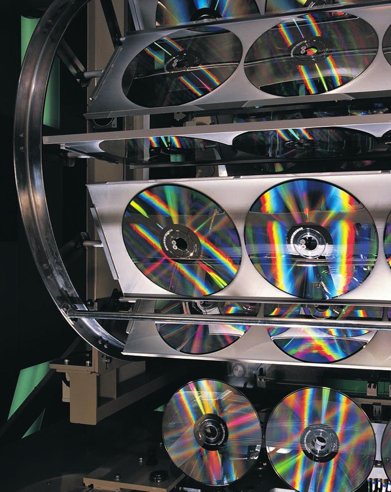
160


161 CHAPTER 15 Interference and Diffraction The streaks of colored light you see coming from a compact disc resemble the colors that appear when white light passes through a prism. However, the compact disc does not separate light by means of refraction. Instead, the light waves undergo interference. WHAT TO EXPECT In this chapter, you will learn about interference of light. In interference, light waves combine to produce resultant waves that are either brighter or less bright than the component waves. WHY IT MATTERS Devices called diffraction gratings use the principle of interference to separate light into its component wavelengths. Diffraction gratings are used in instruments called spectrometers, which are used to study the chemical composition and temperature of stars. CHAPTER PREVIEW For advanced project ideas from Scientific American, visit go.hrw.com and type in the keyword HF6SAF. 1 Interference Combining Light Waves Demonstrating Interference 2 Diffraction The Bending of Light Waves Diffraction Gratings Diffraction and Instrument Resolution 3 Lasers Lasers and Coherence Applications of Lasers 525

162 SECTION 1 Interference SECTION OBJECTIVES Describe how light waves interfere with each other to produce bright and dark fringes. Identify the conditions required for interference to occur. Predict the location of interference fringes using the equation for double-slit interference. Figure 1 Light waves interfere to form bands of color on a soap bubble s surface. COMBINING LIGHT WAVES You have probably noticed the bands of color that form on the surface of a soap bubble, as shown in Figure 1. Unlike the colors that appear when light passes through a refracting substance, these colors are the result of light waves combining with each other. Interference takes place only between waves with the same wavelength To understand how light waves combine with each other, let us review how other kinds of waves combine. If two waves with identical wavelengths interact, they combine to form a resultant wave. This resultant wave has the same wavelength as the component waves, but according to the superposition principle, its displacement at any instant equals the sum of the displacements of the component waves. The resultant wave is the consequence of the interference between the two waves. Figure 2 can be used to describe pairs of mechanical waves or electromagnetic waves with the same wavelength. A light source that has a single wavelength is called monochromatic, which means single colored. In the case of constructive interference, the component waves combine to form a resultant wave with the same wavelength but with an amplitude that is greater than the amplitude of either of the individual component waves. For light, the result of constructive interference is light that is brighter than the light from the contributing waves. In the case of destructive interference, the resultant amplitude is less than the amplitude of the larger component wave. For light, the result of destructive interference is dimmer light or dark spots. Figure 2 Two waves can interfere (a) constructively or (b) destructively. In interference, energy is not lost but is instead redistributed. (a) (b) First wave Second wave Resultant wave First wave Resultant wave Second wave 526 Chapter 15

163 (a) (b) Figure 3 (a) The features of two waves in phase completely match, whereas (b) they are opposite each other in waves that are 180 out of phase. Developed and maintained by the National Science Teachers Association For a variety of links related to this chapter, go to Topic: Interference SciLinks Code: HF60806 Waves must have a constant phase difference for interference to be observed For two waves to produce a stable interference pattern, the phases of the individual waves must remain unchanged relative to one another. If the crest of one wave overlaps the crest of another wave, as in Figure 3(a), the two have a phase difference of 0 and are said to be in phase. If the crest of one wave overlaps the trough of the other wave, as in Figure 3(b), the two waves have a phase difference of 180 and are said to be out of phase. Waves are said to have coherence when the phase difference between two waves is constant and the waves do not shift relative to each other as time passes. Sources of such waves are said to be coherent. When two light bulbs are placed side by side, no interference is observed, even if the lights are the same color. The reason is that the light waves from one bulb are emitted independently of the waves from the other bulb. Random changes occurring in the light from one bulb do not necessarily occur in the light from the other bulb. Thus, the phase difference between the light waves from the two bulbs is not constant. The light waves still interfere, but the conditions for the interference change with each phase change, and therefore, no single interference pattern is observed. Light sources of this type are said to be incoherent. coherence the correlation between the phases of two or more waves DEMONSTRATING INTERFERENCE Interference in light waves from two sources can be demonstrated in the following way. Light from a single source is passed through a narrow slit and then through two narrow parallel slits. The slits serve as a pair of coherent light sources because the waves emerging from them come from the same source. Any random change in the light emitted by the source will occur in the two separate beams at the same time. If monochromatic light is used, the light from the two slits produces a series of bright and dark parallel bands, or fringes, on a distant viewing screen, as shown in Figure 4. When the light from the two slits arrives at a point on the viewing screen where constructive interference occurs, a bright fringe appears Figure 4 An interference pattern consists of alternating light and dark fringes. Interference and Diffraction 527

164 Figure 5 When waves of white light from two coherent sources interfere, the pattern is indistinct because different colors interfere constructively and destructively at different positions. at that location. When the light from the two slits combines destructively at a point on the viewing screen, a dark fringe appears at that location. When a white-light source is used to observe interference, the situation becomes more complicated. The reason is that white light includes waves of many wavelengths. An example of a white-light interference pattern is shown in Figure 5. The interference pattern is stable or well defined at positions where there is constructive interference between light waves of the same wavelength. This explains the color bands on either side of the center band of white light. This effect also accounts for the bands of color seen on soap bubbles. Figure 6 shows some of the ways that two coherent waves leaving the slits can combine at the viewing screen. When the waves arrive at the central point of the screen, as in Figure 6(a), they have traveled equal distances. Thus, they arrive in phase at the center of the screen, constructive interference occurs, and a bright fringe forms at that location. When the two light waves combine at a specific point off the center of the screen, as in Figure 6(b), the wave from the more distant slit must travel one wavelength farther than the wave from the nearer slit. Because the second wave has traveled exactly one wavelength farther than the first wave, the two waves are in phase when they combine at the screen. Constructive interference therefore occurs, and a second bright fringe appears on the screen. If the waves meet midway between the locations of the two bright fringes, as in Figure 6(c), the first wave travels half a wavelength farther than the second wave. In this case, the trough of the first wave overlaps the crest of the second wave, giving rise to destructive interference. Consequently, a dark fringe appears on the viewing screen between the bright fringes. (a) Bright area at (b) (c) center of screen Slits l1 Slits l 2 + λ Center of screen Bright area Slits l λ Center of screen l 1 l 2 l 3 Dark area Figure 6 (a) When both waves of light travel the same distance (l 1 ), they arrive at the screen in phase and interfere constructively. (b) If the difference between the distances traveled by the light from each source equals a whole wavelength (l), the waves still interfere constructively. (c) If the distances traveled by the light differ by a half wavelength, the waves interfere destructively. 528 Chapter 15
165 Predicting the location of interference fringes Consider two narrow slits that are separated by a distance d, as shown in Figure 7, and through which two coherent, monochromatic light waves, l 1 and l 2, pass and are projected onto a screen. If the distance from the slits to the viewing screen is very large compared with the distance between the slits, then l 1 and l 2 are nearly parallel. As a result of this approximation, l 1 and l 2 make the same angle, q, with the horizontal dotted lines that are perpendicular to the slits. The angle q also indicates the position at which the waves combine with respect to the central point of the viewing screen. The difference in the distance traveled by the two waves is called their path difference. Study the right triangle shown in Figure 7, and note that the path difference between the two waves is equal to d sin q. Note carefully that the value for the path difference varies with angle q and that each value of q defines a specific position on the screen. The value of the path difference determines whether the two waves are in or out of phase when they arrive at the viewing screen. If the path difference is either zero or some whole-number multiple of the wavelength, the two waves are in phase, and constructive interference results. The condition for bright fringes (constructive interference) is given by: EQUATION FOR CONSTRUCTIVE INTERFERENCE d sin q = ±ml m = 0,1,2,3,... the path difference between two waves = an integer multiple of the wavelength d θ l 2 dsin θ θ θ l 1 Figure 7 The path difference for two light waves equals d sin q. In order to emphasize the path difference, the figure is not drawn to scale. path difference the difference in the distance traveled by two beams when they are scattered in the same direction from different points In this equation, m is the order number of the fringe. The central bright fringe at q = 0 (m = 0) is called the zeroth-order maximum, or the central maximum; the first maximum on either side of the central maximum, which occurs when m = 1, is called the first-order maximum, and so forth. Similarly, when the path difference is an odd multiple of 1 2 l, the two waves arriving at the screen are 180 out of phase, giving rise to destructive interference. The condition for dark fringes, or destructive interference, is given by the following equation: order number the number assigned to interference fringes with respect to the central bright fringe EQUATION FOR DESTRUCTIVE INTERFERENCE d sin q = ±(m )l m = 0,1,2,3,... the path difference between two waves = an odd number of half wavelengths If m = 0 in this equation, the path difference is ± 1 2 l, which is the condition required for the first dark fringe on either side of the bright central maximum. Interference and Diffraction 529
166 θ θ m Viewing screen Figure 8 The higher-order (m = 1, 2) maxima appear on either side of the central maximum (m = 0). Likewise, if m = 1, the path difference is ± 3 2 l, which is the condition for the second dark fringe on each side of the central maximum, and so forth. A representation of the interference pattern formed by double-slit interference is shown in Figure 8. The numbers indicate the two maxima (the plural of maximum) that form on either side of the central (zeroth-order) maximum. The darkest areas indicate the positions of the dark fringes, or minima (the plural of minimum), that also appear in the pattern. Because the separation between interference fringes varies for light of different wavelengths, double-slit interference provides a method of measuring the wavelength of light. In fact, this technique was used to make the first measurement of the wavelength of light. SAMPLE PROBLEM A Interference PROBLEM SOLUTION 1. DEFINE 2. PLAN The distance between the two slits is mm. The second-order bright fringe (m = 2) is measured on a viewing screen at an angle of 2.15 from the central maximum. Determine the wavelength of the light. Given: d = m m = 2 q = 2.15 Unknown: l =? Diagram: Choose an equation or situation: Use the equation for constructive interference. d sin q = ml Rearrange the equation to isolate the unknown: l = d s in q m d = mm θ = 2.15 Diagram not to scale Second-order bright fringe (m = 2) Zeroth-order bright fringe (m = 0) 3. CALCULATE Substitute the values into the equation and solve: ( m)(sin 2.15 ) l = 2 l = m = nm l = nm CALCULATOR SOLUTION Because the minimum number of significant figures for the data is two, the calculator answer should be rounded to two significant figures. 4. EVALUATE This wavelength of light is in the visible spectrum. The wavelength corresponds to light of a yellow-green color. 530 Chapter 15
167 PRACTICE A Interference 1. A double-slit interference experiment is performed with blue-green light from an argon-gas laser (lasers will be discussed further in Section 3). The separation between the slits is 0.50 mm, and the first-order maximum of the interference pattern is at an angle of from the center of the pattern. What is the wavelength of argon laser light? 2. Light falls on a double slit with slit separation of m, and the first bright fringe is seen at an angle of 16.5 relative to the central maximum. Find the wavelength of the light. 3. A pair of narrow parallel slits separated by a distance of mm is illuminated by the green component from a mercury vapor lamp (l = nm). Calculate the angle from the central maximum to the first bright fringe on either side of the central maximum. 4. Using the data from item 2, determine the angle between the central maximum and the second dark fringe in the interference pattern. SECTION REVIEW 1. What is the necessary condition for a path length difference between two waves that interfere constructively? destructively? 2. If white light is used instead of monochromatic light to demonstrate interference, how does the interference pattern change? 3. If the distance between two slits is mm, find the angle between the first-order and second-order bright fringes for yellow light with a wavelength of 605 nm. Antenna 4. Interpreting Graphics Two radio antennas simultaneously transmit identical signals with a wavelength of 3.35 m, as shown in Figure 9. A radio several miles away in a car traveling parallel to the straight line between the antennas receives the signals. If the second maximum is located at an angle of 1.28 north of the central maximum for the interfering signals, what is the distance, d, between the two antennas? d λ = 3.35 m Car θ = 1.28 Figure 9 Interference and Diffraction 531

168 SECTION 2 Diffraction SECTION OBJECTIVES Describe how light waves bend around obstacles and produce bright and dark fringes. Calculate the positions of fringes for a diffraction grating. Describe how diffraction determines an optical instrument s ability to resolve images. diffraction a change in the direction of a wave when the wave encounters an obstacle, an opening, or an edge THE BENDING OF LIGHT WAVES If you stand near the corner of a building, you can hear someone who is talking around the corner, but you cannot see the person. The reason is that sound waves are able to bend around the corner. In a similar fashion, water waves bend around obstacles, such as the barriers shown in Figure 10. Light waves can also bend around obstacles, but because of their short wavelengths, the amount they bend is too small to be easily observed. If light traveled only in straight lines, you would not be able to observe an interference pattern in the double-slit demonstration. Instead, you would see two thin strips of light where each slit and the source were lined up perfectly. The rest of the screen would be completely dark. The edges of the slits would appear on the screen as sharply defined shadows. But this does not happen. Some of the light bends to the right and to the left as it passes through each slit. The bending of light as it passes through each of the two slits can be understood using Huygens principle, which states that any point on a wave front can be treated as a point source of waves. Because each slit serves as a point source of light, the waves spread out from the slits. The result is that light deviates from a straight-line path and enters the region that would otherwise be shadowed. This divergence of light from its initial direction of travel is called diffraction. In general, diffraction occurs when waves pass through small openings, around obstacles, or by sharp edges. When a wide slit (1 mm or more) is placed between a distant light source and a screen, the light produces a bright rectangle with clearly marked edges on the screen. But if the slit is gradually Figure 10 A property of all waves is that they bend, or diffract, around objects. 532 Chapter 15

169 narrowed, the light eventually begins to spread out and produce a diffraction pattern, such as that shown in Figure 11. Like the interference fringes in the double-slit demonstration, this pattern of light and dark bands arises from the combination of light waves. Wavelets in a wave front interfere with each other Diffraction patterns resemble interference patterns because they also result from constructive and destructive interference. In the case of interference, it is assumed that the slits behave as point sources of light. For diffraction, the actual width of a single slit is considered. According to Huygens principle, each portion of a slit acts as a source of waves. Hence, light from one portion of the slit can interfere with light from another portion. The resultant intensity of the diffracted light on the screen depends on the angle, q, through which the light is diffracted. To understand the single-slit diffraction pattern, consider Figure 12(a), which shows an incoming plane wave passing through a slit of width a. Each point (or, more accurately, each infinitely thin slit) within the wide slit is a source of Huygens wavelets. The figure is simplified by showing only five among this infinite number of sources. As with double-slit interference, the viewing screen is assumed to be so far from the slit that the rays emerging from the slit are nearly parallel. At the viewing screen s midpoint, all rays from the slit travel the same distance, so a bright fringe appears. The wavelets from the five sources can also interfere destructively when they arrive at the screen, as shown in Figure 12(b). When the extra distance traveled by the wave originating at point 3 is half a wavelength longer than the wave from point 1, these two waves interfere destructively at the screen. At this same time, the wave from point 5 travels half a wavelength farther than the wave from point 3, so these waves also interfere destructively. With all pairs of points interfering destructively, this point on the screen is dark. For angles other than those at which destructive interference completely occurs, some of the light waves remain uncanceled. At these angles light appears on the screen as part of a bright band. The brightest band appears in the pattern s center, while the bands to either side are much dimmer. Slit width d 0.8d 0.2d Figure 11 Diffraction becomes more evident as the width of the slit is narrowed. (Note: The wavelength of this light is 5 10 nm.) (a) (b) a Incident wave Central bright fringe Viewing screen 1 2 a θ 1 2 λ λ θ Figure 12 (a) By treating the light coming through the slit as a line of infinitely thin sources along the slit s width, one can determine (b) the conditions at which destructive interference occurs between the waves from the upper half of the slit and the waves from the lower half. Interference and Diffraction 533


170 Minima Minima Developed and maintained by the National Science Teachers Association For a variety of links related to this chapter, go to Topic: Diffraction SciLinks Code: HF60405 Secondary maxima Central maximum Secondary maxima Figure 13 In a diffraction pattern, the central maximum is twice as wide as the secondary maxima. Figure 14 A diffraction pattern forms in the penny s shadow when light is diffracted at the penny s edge. Note the bright spot that is formed at the center of the shadow. Light diffracted by an obstacle also produces a pattern The diffraction pattern that results from monochromatic light passing through a single slit consists of a broad, intense central band the central maximum flanked by a series of narrower, less intense secondary bands (called secondary maxima) and a series of dark bands, or minima. An example of such a pattern is shown in Figure 13. The points at which maximum constructive interference occurs lie approximately halfway between the dark fringes. Note that the central bright fringe is quite a bit brighter and about twice as wide as the next brightest maximum. Diffraction occurs around the edges of all objects. Figure 14 shows the diffraction pattern that appears in the shadow of a penny. The pattern consists of the shadow, with a bright spot at its center, and a series of bright and dark bands of light that continue to the shadow s edge. The penny is large compared with the wavelength of the light, and a magnifying glass is required to observe the pattern. DIFFRACTION GRATINGS Figure 15 Compact discs disperse light into its component colors in a manner similar to that of a diffraction grating. You have probably noticed that if white light is incident on a compact disc, streaks of color are visible. These streaks appear because the digital information (alternating pits and smooth reflecting surfaces) on the disc forms closely spaced rows. These rows of data do not reflect nearly as much light as the thin portions of the disc that separate them. These areas consist entirely of reflecting material, so light reflected from them undergoes constructive interference in certain directions. This constructive interference depends on the direction of the incoming light, the orientation of the disc, and the light s wavelength. Each wavelength of light can be seen at a particular angle with respect to the disc s surface, causing you to see a rainbow of color, as shown in Figure Chapter 15
171 Diffraction grating Lens P d Screen θ d θ dsin θ Figure 16 Light of a single wavelength passes through each of the slits of a diffraction grating to constructively interfere at a particular angle q. This phenomenon has been put to practical use in a device called a diffraction grating. A diffraction grating, which can be constructed to either transmit or reflect light, uses diffraction and interference to disperse light into its component colors with an effect similar to that of a glass prism. A transmission grating consists of many equally spaced parallel slits. Gratings are made by ruling equally spaced lines on a piece of glass using a diamond cutting point driven by an elaborate machine called a ruling engine. Replicas are then made by pouring liquid plastic on the grating and then peeling it off once it has set. This plastic grating is then fastened to a flat piece of glass or plastic for support. Figure 16 shows a schematic diagram of a section of a diffraction grating. A monochromatic plane wave is incoming from the left, normal to the plane of the grating. The waves that emerge nearly parallel from the grating are brought together at a point P on the screen by the lens. The intensity of the pattern on the screen is the result of the combined effects of interference and diffraction. Each slit produces diffraction, and the diffracted beams in turn interfere with one another to produce the pattern. For some arbitrary angle, q, measured from the original direction of travel of the wave, the waves must travel different path lengths before reaching point P on the screen. Note that the path difference between waves from any two adjacent slits is dsin q. If this path difference equals one wavelength or some integral multiple of a wavelength, waves from all slits will be in phase at P, and a bright line will be observed. The condition for bright line formation at angle q is therefore given by the equation for constructive interference: d sin q =±ml m = 0,1,2,3,... This equation can be used to calculate the wavelength of light if you know the grating spacing and the angle of deviation. The integer m is the order number for the bright lines of a given wavelength. If the incident radiation contains several wavelengths, each wavelength deviates by a specific angle, which can be determined from the equation. 1. Spiked Stars Photographs of stars always show spikes extending from the stars. Given that the aperture of a camera s rectangular shutter has straight edges, explain how diffraction accounts for the spikes. 2. Radio Diffraction Visible light waves are not observed diffracting around buildings or other obstacles. However, radio waves can be detected around buildings or mountains, even when the transmitter is not visible. Explain why diffraction is more evident for radio waves than for visible light. Interference and Diffraction 535
172 Diffraction grating Figure 17 Light is dispersed by a diffraction grating. The angle of deviation for the first-order maximum is smaller for blue light than for yellow light. Second order (m = 2) First order (m = 1) Zeroth order (m = 0) First order (m = 1) Second order (m = 2) Slit Source Light rays Lens Telescope Grating Figure 18 The spectrometer uses a grating to disperse the light from a source. θ Note in Figure 17 that all wavelengths combine at q = 0, which corresponds to m = 0. This is called the zeroth-order maximum. The first-order maximum, corresponding to m = 1, is observed at an angle that satisfies the relationship sin q = l/d. The second-order maximum, corresponding to m = 2, is observed at an angle where sin q = 2l/d. The sharpness of the principal maxima and the broad range of the dark areas depend on the number of lines in a grating. The number of lines per unit length in a grating is the inverse of the line separation d. For example, a grating ruled with 5000 lines/cm has a slit spacing, d, equal to the inverse of this number; hence, d = (1/5000) cm = cm. The greater the number of lines per unit length in a grating, the less separation between the slits and the farther spread apart the individual wavelengths of light are. Diffraction gratings are frequently used in devices called spectrometers, which separate the light from a source into its monochromatic components. A diagram of the basic components of a spectrometer is shown in Figure 18. The light to be analyzed passes through a slit and is formed into a parallel beam by a lens. The light then passes through the grating. The diffracted light leaves the grating at angles that satisfy the diffraction grating equation. A telescope with a calibrated scale is used to observe the first-order maxima and to measure the angles at which they appear. From these measurements, the wavelengths of the light can be determined and the chemical composition of the light source can be identified. An example of a spectrum produced by a spectrometer is shown in Figure 19. Spectrometers are used extensively in astronomy to study the chemical compositions and temperatures of stars, interstellar gas clouds, and galaxies. Figure 19 The light from mercury vapor is passed through a diffraction grating, producing the spectrum shown. 536 Chapter 15
173 SAMPLE PROBLEM B Diffraction Gratings PROBLEM SOLUTION 1. DEFINE Monochromatic light from a helium-neon laser (l = nm) shines at a right angle to the surface of a diffraction grating that contains lines/m. Find the angles at which one would observe the firstorder and second-order maxima. Given: l = nm = m m = 1 and d = = m li nes m Unknown: q 1 =? q 2 =? Diagram: Second-order maximum (m = 2) λ = nm Grating θ 2 θ 1 First-order maximum (m = 1) d = 1 m Screen 2. PLAN 3. CALCULATE Choose an equation or situation: Use the equation for a diffraction grating. d sin q =±ml Rearrange the equation to isolate the unknown: q = sin 1 m l d Substitute the values into the equation and solve: For the first-order maximum, m = 1: q 1 = sin 1 l d = sin m 1 m continued on next page q 1 = Interference and Diffraction 537
174 For m = 2: q 2 = sin 1 2 l d q 2 = sin 1 2( m) 1 m CALCULATOR SOLUTION Because the minimum number of significant figures for the data is four, the calculator answers and should be rounded to four significant figures. q 2 = EVALUATE The second-order maximum is spread slightly more than twice as far from the center as the first-order maximum. This diffraction grating does not have high dispersion, and it can produce spectral lines up to the tenth-order maxima (where sin q = ). PRACTICE B Diffraction Gratings 1. A diffraction grating with lines/cm is used to examine the sodium spectrum. Calculate the angular separation of the two closely spaced yellow lines of sodium ( nm and nm) in each of the first three orders. 2. A diffraction grating with 4525 lines/cm is illuminated by direct sunlight. The first-order solar spectrum is spread out on a white screen hanging on a wall opposite the grating. a. At what angle does the first-order maximum for blue light with a wavelength of 422 nm appear? b. At what angle does the first-order maximum for red light with a wavelength of 655 nm appear? 3. A grating with 1555 lines/cm is illuminated with light of wavelength 565 nm. What is the highest-order number that can be observed with this grating? (Hint: Remember that sin q can never be greater than 1 for a diffraction grating.) 4. Repeat item 3 for a diffraction grating with lines/cm that is illuminated with light of wavelength 565 nm. 5. A diffraction grating is calibrated by using the nm line of mercury vapor. The first-order maximum is found at an angle of Calculate the number of lines per centimeter on this grating. 538 Chapter 15

175 DIFFRACTION AND INSTRUMENT RESOLUTION The ability of an optical system, such as a microscope or a telescope, to distinguish between closely spaced objects is limited by the wave nature of light. To understand this limitation, consider Figure 20, which shows two light sources far from a narrow slit. The sources can be taken as two point sources that are not coherent. For example, they could be two distant stars that appear close to each other in the night sky. If no diffraction occurred, you would observe two distinct bright spots (or images) on the screen at the far right. However, because of diffraction, each source is shown to have a bright central region flanked by weaker bright and dark rings. What is observed on the screen is the resultant from the superposition of two diffraction patterns, one from each source. Resolution depends on wavelength and aperture width If the two sources are separated so that their central maxima do not overlap, as in Figure 21, their images can just be distinguished and are said to be barely resolved. To achieve high resolution or resolving power, the angle between the resolved objects, q, should be as small as possible as shown in Figure 20. The shorter the wavelength of the incoming light or the wider the opening, or aperture, through which the light passes, the smaller the angle of resolution, q, will be and the greater the resolving power will be. For visible-light telescopes, the aperture width, D, is approximately equal to the diameter of the mirror or lens. The equation to determine the limiting angle of resolution in radians for an optical instrument with a circular aperture is as follows: Source 1 θ Source 2 Figure 20 Each of two distant point sources produces a diffraction pattern. resolving power the ability of an optical instrument to form separate images of two objects that are close together q = 1.22 D l The constant 1.22 comes from the derivation of the equation for circular apertures and is absent for long slits. Note that one radian equals (180/p), as discussed in the Appendix J feature Angular Kinematics. The equation indicates that for light with a short wavelength, such as an X ray, a small aperture is sufficient for high resolution. On the other hand, if the wavelength of the light is long, as in the case of a radio wave, the aperture must be large in order to resolve distant objects. This is one reason why radio telescopes have large dishlike antennas. Figure 21 Two point sources are barely resolved if the central maxima of their diffraction patterns do not overlap. Interference and Diffraction 539

176 Figure 22 The 27 antennas at the Very Large Array in New Mexico are used together to provide improved resolution for observing distant radio sources. The antennas can be arranged to have the resolving power of a 36 km wide radio telescope. Yet, even with their large sizes, radio telescopes cannot resolve sources as easily as visible-light telescopes resolve visible-light sources. At the shortest radio wavelength (1 mm), the largest single antenna for a radio telescope the 305 m dish at Arecibo, Puerto Rico has a resolution angle of rad. The same resolution angle can be obtained for the longest visible light waves (700 nm) by an optical telescope with a 21 cm mirror. To compensate for the poor resolution of radio waves, one can combine several radio telescopes so that they will function like a much larger telescope. An example of this is shown in Figure 22. If the radio antennas are arranged in a line and computers are used to process the signals that each antenna receives, the resolution of the radio images is the same as it would be if the radio telescope had a diameter of several kilometers. It should be noted that the resolving power for optical telescopes on Earth is limited by the constantly moving layers of air in the atmosphere, which blur the light from objects in space. The images from the Hubble Space Telescope are of superior quality largely because the telescope operates in the vacuum of space. Under these conditions, the actual resolving power of the telescope is close to the telescope s theoretical resolving power. SECTION REVIEW 1. Light passes through a diffraction grating with 3550 lines/cm and forms a first-order maximum at an angle of a. What is the wavelength of the light? b. At what angle will the second maximum appear? 2. Describe the change in width of the central maximum of the single-slit diffraction pattern as the width of the slit is made smaller. 3. Which object would produce the most distinct diffraction pattern: an apple, a pencil lead, or a human hair? Explain your answer. 4. Would orange light or blue light produce a wider diffraction pattern? Explain why. 5. Critical Thinking A point source of light is inside a container that is opaque except for a single hole. Discuss what happens to the image of the point source projected onto a screen as the hole s width is reduced. 6. Critical Thinking Would it be easier to resolve nearby objects if you detected them using ultraviolet radiation rather than visible light? Explain. 540 Chapter 15
177 Lasers SECTION 3 SECTION OBJECTIVES LASERS AND COHERENCE At this point, you are familiar with electromagnetic radiation that is produced by glowing, or incandescent, light sources. This includes light from light bulbs, candle flames, or the sun. You may have seen another form of light that is very different from the light produced by incandescent sources. The light produced by a laser has unique properties that make it very useful for many applications. To understand how laser light is different from conventional light, consider the light produced by an incandescent light bulb, as shown in Figure 23. When electric charges move through the filament, electromagnetic waves are emitted in the form of visible light. In a typical light bulb, there are variations in the structure of the filament and in the way charges move through it. As a result, electromagnetic waves are emitted at different times from different parts of the filament. These waves have different intensities and move in different directions. The light also covers a wide range of the electromagnetic spectrum because it includes light of different wavelengths. Because so many different wavelengths exist, and because the light is changing almost constantly, the light produced is incoherent. That is, the component waves do not maintain a constant phase difference at all times. The wave fronts of incoherent light are like the wave fronts that result when rain falls on the surface of a pond. No two wave fronts are caused by the same event, and they therefore do not produce a stable interference pattern. Describe the properties of laser light. Explain how laser light has particular advantages in certain applications. laser a device that produces coherent light at a single wavelength Did you know? The light from an ordinary electric lamp undergoes about 100 million (10 8 ) random changes every second. Incoherent light Coherent light Figure 23 Waves from an incoherent light source (left) have changing phase relationships, while waves from a coherent light source (right) have constant phase relationships. Interference and Diffraction 541
178 Developed and maintained by the National Science Teachers Association For a variety of links related to this chapter, go to Topic: Lasers SciLinks Code: HF60853 Did you know? The word laser is an acronym (a word made from the first letters of several words) that stands for light amplification by stimulated emission of radiation. Lasers, on the other hand, typically produce a narrow beam of coherent light. The waves emitted by a laser are in phase, and they do not shift relative to each other as time progresses. Because all the waves are in phase, they interfere constructively at all points. The individual waves effectively behave like a single wave with a very large amplitude. In addition, the light produced by a laser is monochromatic, so all the waves have exactly the same wavelength. As a result of these properties, the intensity, or brightness, of laser light can be made much greater than that of incoherent light. For light, intensity is a measure of the energy transferred per unit time over a given area. Lasers transform energy into coherent light A laser is a device that converts light, electrical energy, or chemical energy into coherent light. There are a variety of different types of lasers, but they all have some common features. They all use a substance called the active medium to which energy is added to produce coherent light. The active medium can be a solid, liquid, or gas. The composition of the active medium determines the wavelength of the light produced by the laser. The basic operation of a laser is shown in Figure 24. When high-energy light or electrical or chemical energy is added to the active medium, as in Figure 24(a), the atoms in the active medium absorb some of the energy. You will learn that atoms exist at different energy states in the chapter Atomic (a) Atoms or molecules with added energy Mirror Active medium Energy input Mirror (partially transparent) (b) Stimulated emission Spontaneously emitted light Before stimulated emission Figure 24 (a) Atoms or molecules in the active medium of a laser absorb energy from an external source. (b) When a spontaneously emitted light wave interacts with an atom, it may cause the atom to emit an identical light wave. (c) Stimulated emission increases the amount of coherent light in the active medium, and the coherent waves behave as a single wave. (c) Coherent light output of laser After stimulated emission 542 Chapter 15

179 Physics. When energy is added to an atom that is at a lower energy state, the atom can be excited to a higher energy state. These excited atoms then release their excess energy in the form of electromagnetic radiation when they return to their original, lower energy states. When light of a certain wavelength is applied to excited atoms, the atoms can be induced to release light waves that have the same properties. After one atom spontaneously releases its energy in the form of a light wave, this initial wave can cause other energized atoms to release their excess energy as light waves with the same wavelength, phase, and direction as the initial wave, as shown in Figure 24(b). This process is called stimulated emission. Most of the light produced by stimulated emission escapes out the sides of the glass tube. However, some of the light moves along the length of the tube, producing more stimulated emission as it goes. Mirrors on the ends of the material return these coherent light waves into the active medium, where they stimulate the emission of more coherent light waves, as shown in Figure 24(c). As the light passes back and forth through the active medium, it becomes more and more intense. One of the mirrors is slightly transparent, which allows the intense coherent light to be emitted by the laser. APPLICATIONS OF LASERS There are a wide variety of laser types, with wavelengths ranging from the far infrared to the X-ray region of the spectrum. Scientists have also created masers, devices similar to lasers but operate in the microwave region of the spectrum. Lasers are used in many ways, from common household uses to a wide variety of industrial uses and very specialized medical applications. Lasers are used to measure distances with great precision Of the properties of laser light, the one that is most evident is that it emerges from the laser as a narrow beam. Unlike the light from a light bulb or even the light that is focused by a parabolic reflector, the light from a laser undergoes very little spreading with distance. One reason is that all the light waves emitted by the laser have the same direction. As a result, a laser can be used to measure large distances, because it can be pointed at distant reflectors and the reflected light can be detected. As shown in Figure 25, astronomers direct laser light at particular points on the moon s surface to determine the Earth-to-moon distance. A pulse of light is directed toward one of several 0.25 m 2 reflectors that were placed on the moon s surface by astronauts during the Apollo missions. By knowing the speed of light and measuring the time the light takes to travel to the moon and back, scientists have measured the Earth-to-moon distance to be about km. Geologists use repeated measurements to record changes in the height of Earth s crust from geological processes. Lasers can be used for these measurements even when the height changes by only a few centimeters. Figure 25 A laser beam is fired at reflectors on the moon, which is more than km away. Interference and Diffraction 543


180 THE INSIDE STORY ON COMPACT DISC PLAYERS Disc Pit Land Photoelectrical cell Lens Laser Lens Prism An interesting application of the laser is the compact disc (CD) player. In a CD player, light from a laser is directed through a series of optics toward a compact disc on which the music or data have been digitally recorded. The CD player reads the data in the way the laser light is reflected from the compact disc. In digital recording, a sound signal is sampled at regular intervals of time. Each sampling is converted to an electrical signal, which in turn is converted into a series of binary numbers. Binary numbers consist only of zeros and ones. The binary numbers are coded to contain information about the signal, including the frequencies and harmonics that are present, the volume for the left and right channels, and the speed of the motor that rotates the disc. This process is called analog-todigital (a-d) conversion. These binary, digital data in a CD are stored as a series of pits and smooth areas (called lands) on the surface of the disc. The series of pits and lands is recorded starting at the center of the disc and spiraling outward along tracks in the CD. These tracks are just 500 nm wide and spaced 1600 nm apart. If you could stretch the data track of a CD out, it would be almost 5 km long! When a CD is played, the laser light is reflected off this series of pits and lands into a detector. In fact, the depth of the pit is chosen so that destructive interference occurs when the laser transitions from a pit to a land or from a land to a pit. The detector records the changes in light reflection between the pits and lands as ones and smooth areas as zeros binary data that are then converted back to the analog signal you hear as music. This step is called digital-to-analog (d-a) conversion, and the analog signal can then be amplified to the speaker system. A CD read-only memory (CD-ROM) drive on your computer works in much the same way. Data from a computer are already in a digital format, so no a-d or d-a conversion is needed. Light from a laser is directed toward the surface of the compact disc. Smooth parts of the disc reflect the light back to the photoelectrical cell. You may wonder how a CD-recordable (CD-R) disc is different. These discs don t have any pits and lands at all. Instead, they have a layer of light-sensitive dye sandwiched between a smooth reflective metal, usually aluminum, and clear plastic. A CD-R drive has an additional laser, about 10 times more powerful than a CD reading laser, that writes the digital data along the tracks of the CD-R disc. When the writing laser shines on the light-sensitive dye, the dye turns dark and creates nonreflecting areas along the track. This process creates the digital pattern that behaves like the pits and lands, which a standard CD player can read. A digital versatile disc (DVD) player operates on the same principle. However, the laser in a DVD player has a shorter wavelength than the laser in a CD player. This shorter wavelength allows the DVD player to read data that are spaced closer together than data on a CD. Additionally, some DVDs contain two layers of data and may even be written on both sides! The lower layer of a two-layer DVD has a thinner coating of reflective material, usually gold, that allows some of the light to pass through it so that the upper level of the DVD can be read. 544 Chapter 15
181 Lasers have many applications in medicine Lasers are also used for many medical procedures by making use of the fact that specific body tissues absorb different wavelengths of laser light. For example, lasers can be used to lighten or remove scars and certain types of birthmarks without affecting surrounding tissues. The scar tissue responds to the wavelength of light used in the laser, but other body tissues are protected. Many medical applications of lasers take advantage of the fact that water can be vaporized by high-intensity infrared light produced by carbon dioxide lasers having a wavelength of 10 m. Carbon dioxide lasers can cut through muscle tissue by heating and evaporating the water contained in the cells. One advantage of a laser is that the energy from the laser also coagulates blood in the newly opened blood vessels, thereby reducing blood loss and decreasing the risk of infection. A laser beam can also be trapped in an optical fiber endoscope, which can be inserted through an orifice and directed to internal body structures. As a result, surgeons can stop internal bleeding or remove tumors without performing massive surgery. Lasers can also be used to treat tissues that cannot be reached by conventional surgical methods. For example, some very specific wavelengths of lasers can pass through certain structures at the front of the eye the cornea and lens without damaging them. Therefore, lasers can be effective at treating lesions of the retina, inside the eye. Lasers are used for other eye surgeries, including surgery to correct glaucoma, a condition in which the fluid pressure within the eye is too great. Left untreated, glaucoma can lead to damage of the optic nerve and eventual blindness. Focusing a laser at the clogged drainage port allows a tiny hole to be burned in the tissue, which relieves the pressure. Lasers can also be used to correct nearsightedness by focusing the beam on the central portion of the cornea to cause it to become flatter. Did you know? The principle behind reading the information stored on a compact disc is also the basis for the reading of bar codes found on many products. When these products are scanned, laser light reflected from the bars and spaces of the bar code reproduces the binary codes that represent the product s inventory number. This information is transmitted to the store s computer system, which returns the product s name and price to the cash register. Developed and maintained by the National Science Teachers Association For a variety of links related to this chapter, go to Topic: Bar Codes SciLinks Code: HF60135 SECTION REVIEW 1. How does light from a laser differ from light whose waves all have the same wavelength but are not coherent? 2. The process of stimulated emission involves producing a second wave that is identical to the first. Does this gaining of a second wave violate the principle of energy conservation? Explain your answer. 3. Critical Thinking Fiber-optic systems transmit light by means of internal reflection within thin strands of extremely pure glass. In these fiber-optic systems, laser light is used instead of white light to transmit the signal. Apply your knowledge of refraction to explain why. Interference and Diffraction 545


182 PHYSICS CAREERS Laser Surgeon Laser surgery combines two fields eye care and high-tech engineering to give perfect vision to people who otherwise would need glasses or contacts. To learn more about this career, read the interview with ophthalmologist Dr. L. Shawn Wong, who runs a laser center in Austin, Texas. What sort of education helped you become a laser surgeon? Besides using my medical school training, I use a lot of engineering in my work; physics and math courses are very helpful. In high school, even in junior high, having a love of math and science is extremely helpful. Who helped you find your career path? Of all my teachers, my junior high earth science teacher made the biggest impression on me.what I learned in those classes I actually still use today: problem solving. Interestingly, I work in the town where I grew up; a lot of my former teachers are my patients today. What makes laser surgery interesting to you? It s nice to be able to help people. Unlike glasses and contacts, laser surgery is not a correction; it s a cure.when you are improving people s vision, everybody in the room gets to see the results. I don t need to tell patients they re doing well they can tell. What is the nature of your work? A typical patient is somebody born with poor vision.we make these patients undergo a lot of formal diagnostic testing and informal screening to be sure they are good candidates. Lasers are used for diagnosing as well as treating. Laser tolerances are extremely small we re talking in terms of submicrons, the individual cells of the eye. Dr.Wong makes measurements of the eye in preparation for laser surgery. What is your favorite thing about your job? What would you most like to change about it? My favorite thing is making people visually free. I would like to be able to solve an even wider range of problems.we can t solve everything. How does your work relate to the physics of interference and diffraction? Measuring diffraction and interference is part of every aspect of what we do. The approach is based on doing many small things correctly. Applying small physics principles in the right order can solve very big problems. What advice would you give to somebody who is considering a career in laser surgery? My education didn t start in medical school; it started by asking questions as a kid. You need a genuine love of taking on complex problems. A background in physics and math is extremely helpful. Technology in medicine is based on engineering. Being well rounded will help you get into medical school and get out, too. You have to be comfortable doing the science, but you also have to be comfortable dealing with people. 546 Chapter 15
183 CHAPTER 15 Highlights KEY IDEAS Section 1 Interference Light waves with the same wavelength and constant phase differences interfere with each other to produce light and dark interference patterns. In double-slit interference, the position of a bright fringe requires that the path difference between two interfering point sources be equal to a whole number of wavelengths. In double-slit interference, the position of a dark fringe requires that the path difference between two interfering point sources be equal to an odd number of half wavelengths. Section 2 Diffraction Light waves form a diffraction pattern by passing around an obstacle or bending through a slit and interfering with each other. The position of a maximum in a pattern created by a diffraction grating depends on the separation of the slits in the grating, the order of the maximum, and the wavelength of the light. Section 3 Lasers A laser is a device that transforms energy into a beam of coherent monochromatic light. KEY TERMS coherence (p. 527) path difference (p. 529) order number (p. 529) diffraction (p. 532) resolving power (p. 539) laser (p. 541) PROBLEM SOLVING See Appendix D: Equations for a summary of the equations introduced in this chapter. If you need more problem-solving practice, see Appendix I: Additional Problems. Variable Symbols Quantities Units l wavelength m meters q angle from the center degrees of an interference pattern d slit separation m meters m order number (unitless) Interference and Diffraction 547
184 CHAPTER 15 Review INTERFERENCE Review Questions 1. What happens if two light waves with the same amplitude interfere constructively? What happens if they interfere destructively? 2. Interference in sound is recognized by differences in volume; how is interference in light recognized? 3. A double-slit interference experiment is performed with red light and then again with blue light. In what ways do the two interference patterns differ? (Hint: Consider the difference in wavelength for the two colors of light.) 4. What data would you need to collect to correctly calculate the wavelength of light in a double-slit interference experiment? Conceptual Questions 5. If a double-slit experiment were performed underwater, how would the observed interference pattern be affected? (Hint: Consider how light changes in a medium with a higher index of refraction.) 6. Because of their great distance from us, stars are essentially point sources of light. If two stars were near each other in the sky, would the light from them produce an interference pattern? Explain your answer. 7. Assume that white light is provided by a single source in a double-slit experiment. Describe the interference pattern if one slit is covered with a red filter and the other slit is covered with a blue filter. 8. An interference pattern is formed by using green light and an apparatus in which the two slits can move. If the slits are moved farther apart, will the separation of the bright fringes in the pattern decrease, increase, or remain unchanged? Why? Practice Problems For problems 9 11, see Sample Problem A. 9. Light falls on two slits spaced 0.33 mm apart. If the angle between the first dark fringe and the central maximum is 0.055, what is the wavelength of the light? 10. A sodium-vapor street lamp produces light that is nearly monochromatic. If the light shines on a wooden door in which there are two straight, parallel cracks, an interference pattern will form on a distant wall behind the door. The slits have a separation of mm, and the second-order maximum occurs at an angle of from the central maximum. Determine the following quantities: a. the wavelength of the light b. the angle of the third-order maximum c. the angle of the fourth-order maximum 11. All but two gaps within a set of venetian blinds have been blocked off to create a double-slit system. These gaps are separated by a distance of 3.2 cm. Infrared radiation is then passed through the two gaps in the blinds. If the angle between the central and the second-order maxima in the interference pattern is 0.56, what is the wavelength of the radiation? DIFFRACTION Review Questions 12. Why does light produce a pattern similar to an interference pattern when it passes through a single slit? 13. How does the width of the central region of a single-slit diffraction pattern change as the wavelength of the light increases? 14. Why is white light separated into a spectrum of colors when it is passed through a diffraction grating? 548 Chapter 15

185 15. Why might orbiting telescopes be problematic for the radio portion of the electromagnetic spectrum? Conceptual Questions 16. Monochromatic light shines through two different diffraction gratings. The second grating produces a pattern in which the first-order and second-order maxima are more widely spread apart. Use this information to tell if there are more or fewer lines per centimeter in the second grating than in the first. 17. Why is the resolving power of your eye better at night than during the day? 18. Globular clusters, such as the one shown below, are spherical groupings of stars that form a ring around the Milky Way galaxy. Because there can be millions of stars in a single cluster and because they are distant, resolving individual stars within the cluster is a challenge. Of the following conditions, which would make it easier to resolve the component stars? Which would make it more difficult? 20. If light with a wavelength of 353 nm is passed through the diffraction grating with 795 slits/cm, find the angle at which one would observe the secondorder maximum. 21. By attaching a diffraction-grating spectroscope to an astronomical telescope, one can measure the spectral lines from a star and determine the star s chemical composition. Assume the grating has 3661 lines/cm. a. If the wavelengths of the star s light are nm, nm, and nm, what are the angles at which the first-order spectral lines occur? b. At what angles are these lines found in the second-order spectrum? LASERS Review Questions 22. What properties does laser light have that are not found in the light used to light your home? 23. Laser light is commonly used to demonstrate double-slit interference. Explain why laser light is preferable to light from other sources for observing interference. 24. Give two examples in which the uniform direction of laser light is advantageous. Give two examples in which the high intensity of laser light is advantageous. a. The number of stars per unit volume is half as great. b. The cluster is twice as far away. c. The cluster is observed in the ultraviolet portion instead of in the visible region of the electromagnetic spectrum. d. The telescope s mirror or lens is twice as wide. Practice Problems For problems 19 21, see Sample Problem B. 19. Light with a wavelength of 707 nm is passed through a diffraction grating with 795 slits/cm. Find the angle at which one would observe the firstorder maximum. 25. Laser light is often linearly polarized. How would you show that this statement is true? MIXED REVIEW 26. The nm line in mercury is measured at an angle of 81.0 in the third-order spectrum of a diffraction grating. Calculate the number of lines per centimeter for the grating. 27. Recall from your study of heat and entropy that the entropy of a system is a measure of that system s disorder. Why is it appropriate to describe a laser as an entropy-reducing device? Interference and Diffraction 549
186 28. A double-slit interference experiment is performed using blue light from a hydrogen discharge tube (l = 486 nm). The fifth-order bright fringe in the interference pattern is from the central maximum. How far apart are the two slits separated? 29. A beam containing light of wavelengths l 1 and l 2 passes through a set of parallel slits. In the interference pattern, the fourth bright line of the l 1 light occurs at the same position as the fifth bright line of the l 2 light. If l 1 is known to be nm, what is the value of l 2? 30. Visible light from an incandescent light bulb ranges from nm to nm. When this light is focused on a diffraction grating, the entire firstorder spectrum is seen, but none of the secondorder spectrum is seen. What is the maximum spacing between lines on this grating? 31. In an arrangement to demonstrate double-slit interference, l = 643 nm, q = 0.737, and d = mm. For light from the two slits interfering at this angle, what is the path difference both in millimeters and in terms of the number of wavelengths? Will the interference correspond to a maximum, a minimum, or an intermediate condition? Alternative Assessment 1. Design simulations of interference patterns. Use a computer to draw many concentric circles at regular distances to represent waves traveling from a point source. Photocopy the page onto two transparencies, and lay them on an overhead projector. Vary the distances between source points, and observe how these variations affect interference patterns. Design transparencies with thicker lines with larger separations to explore the effect of wavelength on interference. 2. Investigate the effect of slit separation on interference patterns. Wrap a flashlight or a pen light tightly with tin foil and make pinholes in the foil. First, record the pattern you see on a screen a few inches away with one hole; then, do the same with two holes. How does the distance between the holes affect the distance between the bright parts of the pattern? Draw schematic diagrams of your observations, and compare them with the results of double-slit interference. How would you improve your equipment? 3. Soap bubbles exhibit different colors because light that is reflected from the outer layer of the soap film interferes with light that is refracted and then reflected from the inner layer of the soap film. Given a refractive index of n = 1.35 and thicknesses ranging from 600 nm to 1000 nm for a soap film, can you predict the colors of a bubble? Test your answer by making soap bubbles and observing the order in which the different colors appear. Can you tell the thickness of a soap bubble from its colors? Organize your findings into a chart, or create a computer program to predict the thicknesses of a bubble based on the wavelengths of light it appears to reflect. 4. Thomas Young s 1803 experiment provided crucial evidence for the wave nature of light, but it was met with strong opposition in England until Augustin Fresnel presented his wave theory of light to the French Academy of Sciences in Research the lives and careers of these two scientists. Create a presentation about one of them. The presentation can be in the form of a report, poster, short video, or computer presentation. 5. Research waves that surround you, including those used in commercial, medicinal, and industrial applications. Interpret how the waves characteristics and behaviors make them useful. For example, investigate what kinds of waves are used in medical procedures such as MRI and ultrasound. What are their wavelengths? Research how lasers are used in medicine. How are they used in industry? Prepare a poster or chart describing your findings, and present it to the class. 550 Chapter 15
187 Double-Slit Experiment One of the classic experiments that demonstrate the wave nature of light is the double-slit experiment. In this experiment, light from a single source is passed through a narrow slit and then through two narrow parallel slits. When the light appears on a viewing screen behind the slits, you see a pattern of alternating bright and dark fringes corresponding to constructive and destructive interference of the light. As you studied earlier in the chapter, the bright fringes are described by the following equation. wavelength of the incident wave. Typically, only the first few fringes (m = 0, 1, 2, 3) are bright enough to see. In this graphing calculator activity, you will calculate a table of fringe angles. By analyzing this table, you will gain a better understanding of the relationship between fringe angles, wavelength, and slit separation. Visit go.hrw.com and enter the keyword HF6INFX to find this graphing calculator activity. Refer to Appendix B for instructions on downloading the program for this activity. d sin q = ± ml In this equation, d is the slit separation, q is the fringe angle, m is the order number, and l is the Interference and Diffraction 551
188 Standardized Test Prep MULTIPLE CHOICE 1. In the equations for interference, what does the term d represent? A. the distance from the midpoint between the two slits to the viewing screen B. the distance between the two slits through which a light wave passes C. the distance between two bright interference fringes D. the distance between two dark interference fringes 2. Which of the following must be true for two waves with identical amplitudes and wavelengths to undergo complete destructive interference? F. The waves must be in phase at all times. G. The waves must be 90 out of phase at all times. H. The waves must be 180 out of phase at all times. J. The waves must be 270 out of phase at all times. 3. Which equation correctly describes the condition for observing the third dark fringe in an interference pattern? A. d sin q = l/2 B. d sin q = 3l/2 C. d sin q = 5l/2 D. d sin q = 3l 5. Monochromatic infrared waves with a wavelength of 750 nm pass through two narrow slits. If the slits are 25 m apart, at what angle will the fourthorder bright fringe appear on a viewing screen? A. 4.3 B. 6.0 C. 6.9 D Monochromatic light with a wavelength of 640 nm passes through a diffraction grating that has lines/m. A bright line on a screen appears at an angle of 11.1 from the central bright fringe. What is the order of this bright line? F. m = 2 G. m = 4 H. m = 6 J. m = 8 7. For observing the same object, how many times better is the resolution of the telescope shown on the left in the figure below than that of the telescope shown on the right? A. 4 B. 2 C. 1 2 D Why is the diffraction of sound easier to observe than the diffraction of visible light? F. Sound waves are easier to detect than visible light waves. G. Sound waves have longer wavelengths than visible light waves and so bend more around barriers. H. Sound waves are longitudinal waves, which diffract more than transverse waves. J. Sound waves have greater amplitude than visible light waves. Area of mirror = 80 m 2 Area of mirror = 20 m Chapter 15
189 8. What steps should you employ to design a telescope with a high degree of resolution? F. Widen the aperture, or design the telescope to detect light of short wavelength. G. Narrow the aperture, or design the telescope to detect light of short wavelength. H. Widen the aperture, or design the telescope to detect light of long wavelength. J. Narrow the aperture, or design the telescope to detect light of long wavelength. EXTENDED RESPONSE 14. Radio signals often reflect from objects and recombine at a distance. Suppose you are moving in a direction perpendicular to a radio signal source and its reflected signal. How would interference between these two signals sound on a radio receiver? 9. What is the property of a laser called that causes coherent light to be emitted? A. different intensities B. light amplification C. monochromaticity D. stimulated emission Original radio signal Observer 10. Which of the following is not an essential component of a laser? F. a partially transparent mirror G. a fully reflecting mirror H. a converging lens J. an active medium SHORT RESPONSE 11. Why is laser light useful for the purposes of making astronomical measurements and surveying? 12. A diffraction grating used in a spectrometer causes the third-order maximum of blue light with a wavelength of 490 nm to form at an angle of 6.33 from the central maximum (m = 0). What is the ruling of the grating in lines/cm? 13. Telescopes that orbit Earth provide better images of distant objects because orbiting telescopes are more able to operate near their theoretical resolution than telescopes on Earth. The orbiting telescopes needed to provide high resolution in the visible part of the spectrum are much larger than the orbiting telescopes that provide similar images in the ultraviolet and X-ray portion of the spectrum. Explain why the sizes must vary. Reflected radio signal Base your answers to questions on the information below. In each problem, show all of your work. A double-slit apparatus for demonstrating interference is constructed so that the slits are separated by 15.0 m. A first-order fringe for constructive interference appears at an angle of 2.25 from the zerothorder (central) fringe. 15. What is the wavelength of the light? 16. At what angle would the third-order (m = 3) bright fringe appear? 17. At what angle would the third-order (m = 3) dark fringe appear? Be sure that angles in all calculations involving trigonometric functions are computed in the proper units (degrees or radians). Interference and Diffraction 553
190 CHAPTER 15 Skills Practice Lab Diffraction OBJECTIVE Discover wavelengths of diffracted light. MATERIALS LIST bent paper-clip riders for meterstick black cardboard cellophane tape diffraction grating grating holder and support incandescent light source and power supply meterstick and 2 supports metric scale and slit In this experiment, you will pass white light through a diffraction grating and make measurements to determine wavelengths of the light s components. SAFETY Avoid looking directly at a light source. Looking directly at a light source can cause permanent eye damage. Put on goggles. Use a hot mitt to handle resistors, light sources, and other equipment that may be hot. Allow all equipment to cool before storing it. If a bulb breaks, notify your teacher immediately. Do not remove broken bulbs from sockets. Never put broken glass or ceramics in a regular waste container. Use a dustpan, brush, and heavy gloves to carefully pick up broken pieces and dispose of them in a container specifically provided for this purpose. PROCEDURE Preparation 1. Read the entire lab, and plan the steps you will take. 2. If you are not using a datasheet provided by your teacher, prepare a data table in your lab notebook with six columns and four rows. In the first row, label the columns Light Source, Image Color, Order, Image 1 (m), Image 2 (m), and Slit (m). In the first column, label the second through fourth rows White. Above or below the data table, prepare a space to record the slit spacing, d, of the grating. Wavelengths of White Light 3. Set up the optical bench as shown in Figure 1. Mount the scale and slit on one end of the optical bench, and place a piece of tape over the slit. Place a cardboard shield around the light source to direct all the light through the slit. Illuminate the slit with white light. Mount the grating near the opposite end of the optical bench. 4. Adjust the apparatus so that the white-light source is centered on the slit and the slit scale is perpendicular to the optical bench. Tape the optical bench and the white-light source securely in place. 554 Chapter 15

191 5. With your eye close to the grating, observe the first-order spectra. Move the grating forward or backward as required so that the entire spectrum appears on each side of the scale. Place a bent paper-clip rider on the scale at the point in each first-order spectrum where the yellow light is the purest. Adjust the grating and slit scale by rotating the grating around its vertical axis so that the two yellow points end up equidistant from the source slit. Reposition the riders if necessary. 6. Use the scale to measure the distance from the slit to each rider to the nearest millimeter. Record these distances in your data table as Image 1 and Image 2. Also measure the distance from the slit to the grating. Record this distance in your data table as the Slit (m). Record the order number and the image color. 7. Next, adjust the grating and slit to find the clearest first-order continuous spectrum. Measure and record the distance from the slit to the grating. Place a rider on the scale at the point in each first-order spectrum where you see the extreme end of the violet spectrum. Measure and record the distance from the slit to each rider. 8. Repeat step 7 for the extreme red end of the spectrum. Record all data. 9. Clean up your work area. Put equipment away safely so that it is ready to be used again. Recycle or dispose of used materials as directed by your teacher. Figure 1 Step 3: Use the cardboard to make a shield around the light source. Make sure the light is directed through the slit. Step 4: From above, the slit scale should form right angles with the meterstick. Measurements can be strongly affected if the equipment is moved even slightly during the procedure. Step 5: Place a bent paper-clip rider to mark the position of the images on the scale. ANALYSIS 1. Organizing Data Use your data for each trial. a. For each trial, find the average image position. b. Use the average image position and the distance from the slit to the grating to find the distance from the grating to the image for each trial. (Hint: Use the Pythagorean theorem.) c. To find sin q for each trial, divide the average image position by the distance found in (b). CONCLUSIONS 2. Drawing Conclusions For each trial, find the wavelength of the light using the equation l = d (s inq), where l is the wavelength of light m (in meters, m), d is the diffraction-grating spacing (1/[number of lines/m]), and m is the order number of the spectrum containing the image. Interference and Diffraction 555
Measuring Simple Harmonic Motion
 SECTION 2 Plan and Prepare Preview Vocabulary Scientific Meanings Explain that everyday words have more specialized meanings in science. Ask students the meaning of frequency. They are likely to use the
Section 1 Simple Harmonic Motion. Chapter 11. Preview. Objectives Hooke s Law Sample Problem Simple Harmonic Motion The Simple Pendulum
 Section 1 Simple Harmonic Motion Preview Objectives Hooke s Law Sample Problem Simple Harmonic Motion The Simple Pendulum Section 1 Simple Harmonic Motion Objectives Identify the conditions of simple harmonic
Section 1 Simple Harmonic Motion. The student is expected to:
 Section 1 Simple Harmonic Motion TEKS The student is expected to: 7A examine and describe oscillatory motion and wave propagation in various types of media Section 1 Simple Harmonic Motion Preview Objectives
Chapter 12 Vibrations and Waves Simple Harmonic Motion page
 Chapter 2 Vibrations and Waves 2- Simple Harmonic Motion page 438-45 Hooke s Law Periodic motion the object has a repeated motion that follows the same path, the object swings to and fro. Examples: a pendulum
Outline. Hook s law. Mass spring system Simple harmonic motion Travelling waves Waves in string Sound waves
 Outline Hook s law. Mass spring system Simple harmonic motion Travelling waves Waves in string Sound waves Hooke s Law Force is directly proportional to the displacement of the object from the equilibrium
Raymond A. Serway Chris Vuille. Chapter Thirteen. Vibrations and Waves
 Raymond A. Serway Chris Vuille Chapter Thirteen Vibrations and Waves Periodic Motion and Waves Periodic motion is one of the most important kinds of physical behavior Will include a closer look at Hooke
Chapter 13, Vibrations and Waves. 1. A large spring requires a force of 150 N to compress it only m. What is the spring constant of the spring?
 CHAPTER 13 1. A large spring requires a force of 150 N to compress it only 0.010 m. What is the spring constant of the spring? a. 125 000 N/m b. 15 000 N/m c. 15 N/m d. 1.5 N/m 2. A 0.20-kg object is attached
CHAPTER 11 VIBRATIONS AND WAVES
 CHAPTER 11 VIBRATIONS AND WAVES http://www.physicsclassroom.com/class/waves/u10l1a.html UNITS Simple Harmonic Motion Energy in the Simple Harmonic Oscillator The Period and Sinusoidal Nature of SHM The
Oscillations and Waves
 Oscillations and Waves Periodic Motion Simple Harmonic Motion Connections between Uniform Circular Motion and Simple Harmonic Motion The Period of a Mass on a Spring Energy Conservation in Oscillatory
SIMPLE HARMONIC MOTION
 WAVES SIMPLE HARMONIC MOTION Simple Harmonic Motion (SHM) Vibration about an equilibrium position in which a restoring force is proportional to the displacement from equilibrium TYPES OF SHM THE PENDULUM
Oscillations - AP Physics B 1984
 Oscillations - AP Physics B 1984 1. If the mass of a simple pendulum is doubled but its length remains constant, its period is multiplied by a factor of (A) 1 2 (B) (C) 1 1 2 (D) 2 (E) 2 A block oscillates
Lectures Chapter 10 (Cutnell & Johnson, Physics 7 th edition)
") PH 201-4A spring 2007 Simple Harmonic Motion Lectures 24-25 Chapter 10 (Cutnell & Johnson, Physics 7 th edition) 1 The Ideal Spring Springs are objects that exhibit elastic behavior. It will return back
PH 201-4A spring 2007 Simple Harmonic Motion Lectures 24-25 Chapter 10 (Cutnell & Johnson, Physics 7 th edition) 1 The Ideal Spring Springs are objects that exhibit elastic behavior. It will return back
FIGURE P13.5 FIGURE P13.6. Chapter 13 Problems
 Chapter 13 Problems 1, 2, 3 = straightforward, intermediate, challenging Section 13.1 Hooke s Law 5. The springs 1 and 2 in Figure P13.5 have spring constants of 40.0 N/cm and 25.0 N/cm, respectively.
AP physics B - Webreview ch 13 Waves
 Name: Class: _ Date: _ AP physics B - Webreview ch 13 Waves Multiple Choice Identify the choice that best completes the statement or answers the question. 1. A large spring requires a force of 150 N to
1. a) A flag waving in the breeze flaps once each s. What is the period and frequency of the flapping flag?
 A flag waving in the breeze flaps once each s. What is the period and frequency of the flapping flag?") PHYSICS 20N UNIT 4 REVIEW NAME: Be sure to show explicit formulas and substitutions for all calculational questions, where appropriate. Round final answers correctly; give correct units. Be sure to show
PHYSICS 20N UNIT 4 REVIEW NAME: Be sure to show explicit formulas and substitutions for all calculational questions, where appropriate. Round final answers correctly; give correct units. Be sure to show
Oscillatory Motion and Wave Motion
 Oscillatory Motion and Wave Motion Oscillatory Motion Simple Harmonic Motion Wave Motion Waves Motion of an Object Attached to a Spring The Pendulum Transverse and Longitudinal Waves Sinusoidal Wave Function
Pre-AP Physics Review Problems
 Pre-AP Physics Review Problems SECTION ONE: MULTIPLE-CHOICE QUESTIONS (50x2=100 points) 1. The graph above shows the velocity versus time for an object moving in a straight line. At what time after t =
f 1/ T T 1/ f Formulas Fs kx m T s 2 k l T p 2 g v f
 f 1/T Formulas T 1/ f Fs kx Ts 2 m k Tp 2 l g v f What do the following all have in common? Swing, pendulum, vibrating string They all exhibit forms of periodic motion. Periodic Motion: When a vibration
Oscillations and Waves
 Oscillations and Waves Oscillation: Wave: Examples of oscillations: 1. mass on spring (eg. bungee jumping) 2. pendulum (eg. swing) 3. object bobbing in water (eg. buoy, boat) 4. vibrating cantilever (eg.
CHAPTER 7: OSCILLATORY MOTION REQUIRES A SET OF CONDITIONS
 CHAPTER 7: OSCILLATORY MOTION REQUIRES A SET OF CONDITIONS 7.1 Period and Frequency Anything that vibrates or repeats its motion regularly is said to have oscillatory motion (sometimes called harmonic
Simple Harmonic Motion *
 OpenStax-CNX module: m54154 1 Simple Harmonic Motion * OpenStax HS Physics This work is produced by OpenStax-CNX and licensed under the Creative Commons Attribution License 4.0 1 : By the end of this section,
Standing waves [49 marks]
![Standing waves [49 marks]](/thumbs/92/110837906.jpg "Standing waves [49 marks]") Standing waves [49 marks] 1. The graph shows the variation with time t of the velocity v of an object undergoing simple harmonic motion (SHM). At which velocity does the displacement from the mean position
Standing waves [49 marks] 1. The graph shows the variation with time t of the velocity v of an object undergoing simple harmonic motion (SHM). At which velocity does the displacement from the mean position
2016 AP Physics Unit 6 Oscillations and Waves.notebook December 09, 2016
 AP Physics Unit Six Oscillations and Waves 1 2 A. Dynamics of SHM 1. Force a. since the block is accelerating, there must be a force acting on it b. Hooke's Law F = kx F = force k = spring constant x =
Chapter 14 Oscillations. Copyright 2009 Pearson Education, Inc.
 Chapter 14 Oscillations Oscillations of a Spring Simple Harmonic Motion Energy in the Simple Harmonic Oscillator Simple Harmonic Motion Related to Uniform Circular Motion The Simple Pendulum The Physical
WAVES & SIMPLE HARMONIC MOTION
 PROJECT WAVES & SIMPLE HARMONIC MOTION EVERY WAVE, REGARDLESS OF HOW HIGH AND FORCEFUL IT CRESTS, MUST EVENTUALLY COLLAPSE WITHIN ITSELF. - STEFAN ZWEIG What s a Wave? A wave is a wiggle in time and space
Chapter 11 Vibrations and Waves
 Chapter 11 Vibrations and Waves 11-1 Simple Harmonic Motion If an object vibrates or oscillates back and forth over the same path, each cycle taking the same amount of time, the motion is called periodic.
5. A car moves with a constant speed in a clockwise direction around a circular path of radius r, as represented in the diagram above.
 1. The magnitude of the gravitational force between two objects is 20. Newtons. If the mass of each object were doubled, the magnitude of the gravitational force between the objects would be A) 5.0 N B)
Good Vibes: Introduction to Oscillations
 Chapter 14 Solutions Good Vibes: Introduction to Oscillations Description: Several conceptual and qualitative questions related to main characteristics of simple harmonic motion: amplitude, displacement,
SOUND. Representative Sample Physics: Sound. 1. Periodic Motion of Particles PLANCESS CONCEPTS
 Representative Sample Physics: Sound SOUND 1. Periodic Motion of Particles Before we move on to study the nature and transmission of sound, we need to understand the different types of vibratory or oscillatory
Virbations and Waves
 Virbations and Waves 1.1 Observe and find a pattern Try the following simple experiments and describe common patterns concerning the behavior of the block. (a) Fill in the table that follows. Experiment
Chapter 15. Mechanical Waves
 Chapter 15 Mechanical Waves A wave is any disturbance from an equilibrium condition, which travels or propagates with time from one region of space to another. A harmonic wave is a periodic wave in which
Chapter 14 Preview Looking Ahead
 Chapter 14 Preview Looking Ahead Text: p. 438 Slide 14-1 Chapter 14 Preview Looking Back: Springs and Restoring Forces In Chapter 8, you learned that a stretched spring exerts a restoring force proportional
The net force on a moving object is suddenly reduced to zero. As a consequence, the object
 The net force on a moving object is suddenly reduced to zero. As a consequence, the object (A) stops abruptly (B) stops during a short time interval (C) changes direction (D) continues at a constant velocity
Chapter 13. Hooke s Law: F = - kx Periodic & Simple Harmonic Motion Springs & Pendula Waves Superposition. Next Week!
 Chapter 13 Hooke s Law: F = - kx Periodic & Simple Harmonic Motion Springs & Pendula Waves Superposition Next Week! Review Physics 2A: Springs, Pendula & Circular Motion Elastic Systems F = kx Small Vibrations
Chapter 16 Waves in One Dimension
 Lecture Outline Chapter 16 Waves in One Dimension Slide 16-1 Chapter 16: Waves in One Dimension Chapter Goal: To study the kinematic and dynamics of wave motion, i.e., the transport of energy through a
4. What is the speed (in cm s - 1 ) of the tip of the minute hand?
 of the tip of the minute hand?") Topic 4 Waves PROBLEM SET Formative Assessment NAME: TEAM: THIS IS A PRACTICE ASSESSMENT. Show formulas, substitutions, answers, and units! Topic 4.1 Oscillations A mass is attached to a horizontal spring.
Topic 4 Waves PROBLEM SET Formative Assessment NAME: TEAM: THIS IS A PRACTICE ASSESSMENT. Show formulas, substitutions, answers, and units! Topic 4.1 Oscillations A mass is attached to a horizontal spring.
G r a d e 1 1 P h y s i c s ( 3 0 s ) Final Practice exam
 Final Practice exam") G r a d e 1 1 P h y s i c s ( 3 0 s ) Final Practice exam G r a d e 1 1 P h y s i c s ( 3 0 s ) Final Practice Exam Instructions The final exam will be weighted as follows: Modules 1 6 15 20% Modules
G r a d e 1 1 P h y s i c s ( 3 0 s ) Final Practice exam G r a d e 1 1 P h y s i c s ( 3 0 s ) Final Practice Exam Instructions The final exam will be weighted as follows: Modules 1 6 15 20% Modules
Physics Semester 2 Final Exam Review Answers
 Physics Semester 2 Final Exam Review Answers A student attaches a string to a 3 kg block resting on a frictionless surface, and then pulls steadily (with a constant force) on the block as shown below.
AP Physics 1 Waves and Simple Harmonic Motion Practice Test
 AP Physics 1 Waves and Simple Harmonic Motion Practice Test MULTIPLE CHOICE. Choose the one alternative that best completes the statement or answers the question. 1) An object is attached to a vertical
9.1 Harmonic Motion. Motion in cycles. linear motion - motion that goes from one place to another without repeating.
 9.1 Harmonic Motion A bicyclist pedaling past you on the street moves in linear motion. Linear motion gets us from one place to another (Figure 9.1A). This chapter is about another kind of motion called
Good Vibes: Introduction to Oscillations
 Good Vibes: Introduction to Oscillations Description: Several conceptual and qualitative questions related to main characteristics of simple harmonic motion: amplitude, displacement, period, frequency,
AP Physics Free Response Practice Oscillations
 AP Physics Free Response Practice Oscillations 1975B7. A pendulum consists of a small object of mass m fastened to the end of an inextensible cord of length L. Initially, the pendulum is drawn aside through
AP Physics 1 Multiple Choice Questions - Chapter 9
 1 If an object of mass m attached to a light spring is replaced by one of mass 9m, the frequency of the vibrating system changes by what multiplicative factor? a 1/9 b 1/3 c 3 d 9 e 6 2 A mass of 0.40
Second Semester Review
 Second Semester Review Name Section 4.2 1. Define energy What is energy? Explain if it is scalar or vector in nature. 2. Explain what factors affect the speed of a rollercoaster. Whether a rollercoaster
Physics 101 Lecture 18 Vibrations, SHM, Waves (II)
") Physics 101 Lecture 18 Vibrations, SHM, Waves (II) Reminder: simple harmonic motion is the result if we have a restoring force that is linear with the displacement: F = -k x What would happen if you could
Physics 101 Lecture 18 Vibrations, SHM, Waves (II) Reminder: simple harmonic motion is the result if we have a restoring force that is linear with the displacement: F = -k x What would happen if you could
Simple Harmonic Motion: A Special Periodic Motion
 Simple Harmonic Motion: A Special Periodic Motion Bởi: OpenStaxCollege The oscillations of a system in which the net force can be described by Hooke s law are of special importance, because they are very
CLASS 2 CLASS 2. Section 13.5
 CLASS 2 CLASS 2 Section 13.5 Simple Pendulum The simple pendulum is another example of a system that exhibits simple harmonic motion The force is the component of the weight tangent to the path of motion
Practice Test SHM with Answers
 Practice Test SHM with Answers MPC 1) If we double the frequency of a system undergoing simple harmonic motion, which of the following statements about that system are true? (There could be more than one
SPRING 2004 Final Exam, Part A
 Physics 151 SPRING 2004 Final Exam, Part A Roster No.: Score: 23 pts. possible Exam time limit: 120 minutes. You may use calculators and both sides of 2 pages of notes, handwritten only. Closed book; no
PHYS 1303 Final Exam Example Questions
 PHYS 1303 Final Exam Example Questions (In summer 2014 we have not covered questions 30-35,40,41) 1.Which quantity can be converted from the English system to the metric system by the conversion factor
Homework #4 Reminder Due Wed. 10/6
 Homework #4 Reminder Chap. 6 Concept: 36 Problems 14, 18 Chap. 8 Concept: 8, 12, 30, 34 Problems 2, 10 Due Wed. 10/6 Chapter 8: Wave Motion A wave is a sort of motion But unlike motion of particles A propagating
Chapter 16: Oscillatory Motion and Waves. Simple Harmonic Motion (SHM)
") Chapter 6: Oscillatory Motion and Waves Hooke s Law (revisited) F = - k x Tthe elastic potential energy of a stretched or compressed spring is PE elastic = kx / Spring-block Note: To consider the potential
Chapter 6: Oscillatory Motion and Waves Hooke s Law (revisited) F = - k x Tthe elastic potential energy of a stretched or compressed spring is PE elastic = kx / Spring-block Note: To consider the potential
A body is displaced from equilibrium. State the two conditions necessary for the body to execute simple harmonic motion
 1. Simple harmonic motion and the greenhouse effect (a) A body is displaced from equilibrium. State the two conditions necessary for the body to execute simple harmonic motion. 1. 2. (b) In a simple model
3.The wrecking crane shown is moving toward a brick wall that is to be torn down.
 Test Name: Physics Practice Test Section 1 1.Which of the following best classifies a material that has extremely low conductivity? 1. A. semiconductor B. insulator C. metalloid D. conductor 2.Which of
End-of-Chapter Exercises
 End-of-Chapter Exercises Exercises 1 12 are conceptual questions that are designed to see if you have understood the main concepts of the chapter. 1. When a spring is compressed 10 cm, compared to its
PHYSICS 1 Simple Harmonic Motion
 Advanced Placement PHYSICS 1 Simple Harmonic Motion Student 014-015 What I Absolutely Have to Know to Survive the AP* Exam Whenever the acceleration of an object is proportional to its displacement and
Quantitative Skills in AP Physics 1
 This chapter focuses on some of the quantitative skills that are important in your AP Physics 1 course. These are not all of the skills that you will learn, practice, and apply during the year, but these
11. (7 points: Choose up to 3 answers) What is the tension,!, in the string? a.! = 0.10 N b.! = 0.21 N c.! = 0.29 N d.! = N e.! = 0.
 What is the tension,!, in the string? a.! = 0.10 N b.! = 0.21 N c.! = 0.29 N d.! = N e.! = 0.") A harmonic wave propagates horizontally along a taut string of length! = 8.0 m and mass! = 0.23 kg. The vertical displacement of the string along its length is given by!!,! = 0.1!m cos 1.5!!! +!0.8!!,
A harmonic wave propagates horizontally along a taut string of length! = 8.0 m and mass! = 0.23 kg. The vertical displacement of the string along its length is given by!!,! = 0.1!m cos 1.5!!! +!0.8!!,
Chapter 14 Oscillations. Copyright 2009 Pearson Education, Inc.
 Chapter 14 Oscillations 14-1 Oscillations of a Spring If an object vibrates or oscillates back and forth over the same path, each cycle taking the same amount of time, the motion is called periodic. The
Work. Work and Energy Examples. Energy. To move an object we must do work Work is calculated as the force applied to the object through a distance or:
 Work To move an object we must do work Work is calculated as the force applied to the object through a distance or: W F( d) Work has the units Newton meters (N m) or Joules 1 Joule = 1 N m Energy Work
Chapter 15. Oscillatory Motion
 Chapter 15 Oscillatory Motion Part 2 Oscillations and Mechanical Waves Periodic motion is the repeating motion of an object in which it continues to return to a given position after a fixed time interval.
No Brain Too Small PHYSICS
 MECHANICS: SIMPLE HARMONIC MOTION QUESTIONS SIMPLE HARMONIC MOTION (2016;3) A toy bumble bee hangs on a spring suspended from the ceiling in the laboratory. Tom pulls the bumble bee down 10.0 cm below
Chapter 8: Wave Motion. Homework #4 Reminder. But what moves? Wave properties. Waves can reflect. Waves can pass through each other
 Homework #4 Reminder Chap. 6 Concept: 36 Problems 14, 18 Chap. 8 Concept: 8, 12, 30, 34 Problems 2, 10 Chapter 8: Wave Motion A wave is a sort of motion But unlike motion of particles A propagating disturbance
Chapter 6 Energy and Oscillations
 Chapter 6 Energy and Oscillations Conservation of Energy In this chapter we will discuss one of the most important and fundamental principles in the universe. Energy is conserved. This means that in any
Simple Harmonic Motion Test Tuesday 11/7
 Simple Harmonic Motion Test Tuesday 11/7 Chapter 11 Vibrations and Waves 1 If an object vibrates or oscillates back and forth over the same path, each cycle taking the same amount of time, the motion is
Periodic Motion. Periodic motion is motion of an object that. regularly repeats
 Periodic Motion Periodic motion is motion of an object that regularly repeats The object returns to a given position after a fixed time interval A special kind of periodic motion occurs in mechanical systems
(Total 1 mark) IB Questionbank Physics 1
 IB Questionbank Physics 1") 1. A transverse wave travels from left to right. The diagram below shows how, at a particular instant of time, the displacement of particles in the medium varies with position. Which arrow represents the
1. A transverse wave travels from left to right. The diagram below shows how, at a particular instant of time, the displacement of particles in the medium varies with position. Which arrow represents the
Chapter 14: Periodic motion
 Chapter 14: Periodic motion Describing oscillations Simple harmonic motion Energy of simple harmonic motion Applications of simple harmonic motion Simple pendulum & physical pendulum Damped oscillations
Chapter 14 Oscillations
 Chapter 14 Oscillations If an object vibrates or oscillates back and forth over the same path, each cycle taking the same amount of time, the motion is called periodic. The mass and spring system is a
4.1 KINEMATICS OF SIMPLE HARMONIC MOTION 4.2 ENERGY CHANGES DURING SIMPLE HARMONIC MOTION 4.3 FORCED OSCILLATIONS AND RESONANCE Notes
 4.1 KINEMATICS OF SIMPLE HARMONIC MOTION 4.2 ENERGY CHANGES DURING SIMPLE HARMONIC MOTION 4.3 FORCED OSCILLATIONS AND RESONANCE Notes I. DEFINING TERMS A. HOW ARE OSCILLATIONS RELATED TO WAVES? II. EQUATIONS
(Total 1 mark) IB Questionbank Physics 1
 IB Questionbank Physics 1") 1. A transverse wave travels from left to right. The diagram below shows how, at a particular instant of time, the displacement of particles in the medium varies with position. Which arrow represents the
1. A transverse wave travels from left to right. The diagram below shows how, at a particular instant of time, the displacement of particles in the medium varies with position. Which arrow represents the
ConcepTest PowerPoints
 ConcepTest PowerPoints Chapter 11 Physics: Principles with Applications, 6 th edition Giancoli 2005 Pearson Prentice Hall This work is protected by United States copyright laws and is provided solely for
Lecture Presentation Chapter 14 Oscillations
 Lecture Presentation Chapter 14 Oscillations Suggested Videos for Chapter 14 Prelecture Videos Describing Simple Harmonic Motion Details of SHM Damping and Resonance Class Videos Oscillations Basic Oscillation
Chapter 16 Lectures. Oscillatory Motion and Waves
 Chapter 16 Lectures January-06-18 5:48 PM Oscillatory Motion and Waves Oscillations are back-and-forth motions. Sometimes the word vibration is used in place of oscillation; for our purposes, we can consider
SIMPLE HARMONIC MOTION AND WAVES
 Simple Harmonic Motion (SHM) SIMPLE HARMONIC MOTION AND WAVES - Periodic motion any type of motion that repeats itself in a regular cycle. Ex: a pendulum swinging, a mass bobbing up and down on a spring.
Chapter 14. Oscillations. Oscillations Introductory Terminology Simple Harmonic Motion:
 Chapter 14 Oscillations Oscillations Introductory Terminology Simple Harmonic Motion: Kinematics Energy Examples of Simple Harmonic Oscillators Damped and Forced Oscillations. Resonance. Periodic Motion
frictionless horizontal surface. The bullet penetrates the block and emerges with a velocity of o
 AP Physics Free Response Practice Momentum and Impulse 1976B2. A bullet of mass m and velocity v o is fired toward a block of mass 4m. The block is initially at rest on a v frictionless horizontal surface.
AP PHYSICS 1. Energy 2016 EDITION
 AP PHYSICS 1 Energy 2016 EDITION Copyright 2016 National Math + Initiative, Dallas, Texas. All rights reserved. Visit us online at www.nms.org. 1 Pre-Assessment Questions Consider a system which could
AP Physics C Mechanics
 1 AP Physics C Mechanics Simple Harmonic Motion 2015 12 05 www.njctl.org 2 Table of Contents Click on the topic to go to that section Spring and a Block Energy of SHM SHM and UCM Simple and Physical Pendulums
AP Physics B Summer Assignment
 BERGEN COUNTY TECHNICAL SCHOOL AP Physics B Summer Assignment 2011 Solve all problems on separate paper. This will be due the first week of school. If you need any help you can e-mail Mr. Zavorotniy at
4 A mass-spring oscillating system undergoes SHM with a period T. What is the period of the system if the amplitude is doubled?
 Slide 1 / 52 1 A block with a mass M is attached to a spring with a spring constant k. The block undergoes SHM. Where is the block located when its velocity is a maximum in magnitude? A 0 B + or - A C
PHYSICS 1. Section I 40 Questions Time 90 minutes. g = 10 m s in all problems.
 Note: To simplify calculations, you may use PHYSICS 1 Section I 40 Questions Time 90 minutes 2 g = 10 m s in all problems. Directions: Each of the questions or incomplete statements below is followed by
SPRING 2003 Final Exam, Part A
 Physics 151 SPRING 2003 Final Exam, Part A Roster No.: Score: 17 pts. possible Exam time limit: 2 hours. You may use calculators and both sides of 2 sheets of notes, handwritten only. Closed book; no collaboration.
2016 PHYSICS FINAL REVIEW PACKET
 2016 PHYSICS FINAL REVIEW PACKET EXAM BREAKDOWN CHAPTER TOPIC # OF QUESTIONS 6 CONSERVATION OF ENERGY 22 7 MOMENTUM/COLLISIONS 17 5 CIRCULAR MOTION GRAVITY/SATELLITE MOTION 30 11 WAVES 24 - ELECTROMAGNETISM/MISC./LABS
RELEASED. Go to next page. 2. The graph shows the acceleration of a car over time.
 1. n object is launched across a room. How can a student determine the average horizontal velocity of the object using a meter stick and a calculator? The student can calculate the object s initial potential
Lecture 17. Mechanical waves. Transverse waves. Sound waves. Standing Waves.
 Lecture 17 Mechanical waves. Transverse waves. Sound waves. Standing Waves. What is a wave? A wave is a traveling disturbance that transports energy but not matter. Examples: Sound waves (air moves back
Simple Harmonic Motion Practice Problems PSI AP Physics 1
 Simple Harmonic Motion Practice Problems PSI AP Physics 1 Name Multiple Choice Questions 1. A block with a mass M is attached to a spring with a spring constant k. The block undergoes SHM. Where is the
Physics General Physics. Lecture 24 Oscillating Systems. Fall 2016 Semester Prof. Matthew Jones
 Physics 22000 General Physics Lecture 24 Oscillating Systems Fall 2016 Semester Prof. Matthew Jones 1 2 Oscillating Motion We have studied linear motion objects moving in straight lines at either constant
Solution The light plates are at the same heights. In balance, the pressure at both plates has to be the same. m g A A A F A = F B.
 43. A piece of metal rests in a toy wood boat floating in water in a bathtub. If the metal is removed from the boat, and kept out of the water, what happens to the water level in the tub? A) It does not
for any object. Note that we use letter, m g, meaning gravitational
 Lecture 4. orces, Newton's Second Law Last time we have started our discussion of Newtonian Mechanics and formulated Newton s laws. Today we shall closely look at the statement of the second law and consider
St. Joseph s Anglo-Chinese School
 Time allowed:.5 hours Take g = 0 ms - if necessary. St. Joseph s Anglo-Chinese School 008 009 First Term Examination Form 6 ASL Physics Section A (40%) Answer ALL questions in this section. Write your
PHYSICS. Chapter 5 Lecture FOR SCIENTISTS AND ENGINEERS A STRATEGIC APPROACH 4/E RANDALL D. KNIGHT Pearson Education, Inc.
 PHYSICS FOR SCIENTISTS AND ENGINEERS A STRATEGIC APPROACH 4/E Chapter 5 Lecture RANDALL D. KNIGHT Chapter 5 Force and Motion IN THIS CHAPTER, you will learn about the connection between force and motion.
Oscillation the vibration of an object. Wave a transfer of energy without a transfer of matter
 Oscillation the vibration of an object Wave a transfer of energy without a transfer of matter Equilibrium Position position of object at rest (mean position) Displacement (x) distance in a particular direction
Unit 4 Waves and Sound Waves and Their Properties
 Lesson35.notebook May 27, 2013 Unit 4 Waves and Sound Waves and Their Properties Today's goal: I can explain the difference between transverse and longitudinal waves and their properties. Waves are a disturbances
Regents Physics. Physics Midterm Review - Multiple Choice Problems
 Name Physics Midterm Review - Multiple Choice Problems Regents Physics 1. A car traveling on a straight road at 15.0 meters per second accelerates uniformly to a speed of 21.0 meters per second in 12.0
QuickCheck 1.5. An ant zig-zags back and forth on a picnic table as shown. The ant s distance traveled and displacement are
 APPY1 Review QuickCheck 1.5 An ant zig-zags back and forth on a picnic table as shown. The ant s distance traveled and displacement are A. 50 cm and 50 cm B. 30 cm and 50 cm C. 50 cm and 30 cm D. 50 cm
Physics Mid-Term Practice Exam
 Physics Mid-Term Practice Exam Multiple Choice. Identify the choice that best completes the statement or answers the question. 1. Which one of the following problems would NOT be a part of physics? a.
MULTIPLE CHOICE. Choose the one alternative that best completes the statement or answers the question.
 Exam Name MULTIPLE CHOICE. Choose the one alternative that best completes the statement or answers the question. 1) A 4.8-kg block attached to a spring executes simple harmonic motion on a frictionless
Schedule for the remainder of class
 Schedule for the remainder of class 04/25 (today): Regular class - Sound and the Doppler Effect 04/27: Cover any remaining new material, then Problem Solving/Review (ALL chapters) 04/29: Problem Solving/Review