A COMPUTATIONAL FLUID DYNAMICS STUDY OF CLAP AND FLING IN THE SMALLEST INSECTS. Laura A. Miller* and Charles S. Peskin**
|
|
|
- Nigel Fitzgerald
- 5 years ago
- Views:
Transcription
1 A COMPUTATIONAL FLUID DYNAMICS STUDY OF CLAP AND FLING IN THE SMALLEST INSECTS Laura A. Miller* and Charles S. Peskin** *Department of Mathematics, University of Utah, 155 South 1400 East, Salt Lake City, UT 84112, and **Courant Institute of Mathematical Sciences, New York University, 251 Mercer Street, New York, NY 10012, USA Summary In this paper, we have used the immersed boundary method to solve the twodimensional Navier-Stokes equations with two immersed wings performing an idealized clap and fling stroke and a fling half stroke. We calculated lift coefficients as a function of time per wing for a range of Reynolds numbers between 8 and 128. We also calculated the instantaneous streamlines around each wing throughout the stroke cycle and related the changes in lift to the relative strength and position of the leading and trailing edge vortices. Our results show that lift generation per wing during the clap and fling of two wings when compared to the average lift produced by one wing with the same motion falls into two distinct patterns. For Reynolds numbers of 64 and higher, lift is initially enhanced during the rotation of two wings when lift coefficients are compared to the case of one wing. Lift coefficients after fling and during the translational part of the stroke oscillate as the leading and trailing edge vortices are -1-
2 alternately shed, and are not substantially greater than the one-winged case. This differs from the three-dimensional case of insect flight where the leading edge vortex remains attached to the wing. For Reynolds numbers of 32 and lower, lift coefficients per wing are also enhanced during wing rotation when compared to the case of one wing rotating with the same motion. Remarkably, lift coefficients following two-winged fling during the translational phase are also enhanced when compared to the one-winged case. Indeed, they begin about 70% higher than the one-winged case during pure translation. When averaged over the entire translational part of the stroke, lift coefficients per wing are 35% higher for the twowinged case during a 4.5 chord translation following fling. In addition, lift enhancement increases with decreasing Reynolds number. This result suggests that the Weis-Fogh mechanism of lift generation has greater benefit to insects flying at lower Reynolds numbers. However, drag coefficients produced during fling are also substantially higher for the two-winged case than the one-winged case, particularly at lower Reynolds numbers. Introduction While analyzing the hovering motion of the tiny wasp Encarsaria formosa, Weis-Fogh (1973) proposed a novel aerodynamic mechanism that enhanced lift during flight. This mechanism became known as the Weis-Fogh mechanism, and the corresponding motion has been termed clap and fling. Lighthill (1973) described analytically how this motion is thought to augment lift using two-dimensional inviscid theory. Later studies revealed -2-
3 that clap and fling is also used by insects such as the greenhouse white-fly Trialeurodes vaporariorium (Weis-Fogh, 1975), thrips (Ellington, 1984), and butterflies (Srygley and Thomas, 2002). Although most, if not all, tiny insects use clap and fling, the majority of insects do not (Ellington, 1999). Moreover, clap and fling could be merely a result of the insect maximizing stroke amplitude rather than an independently evolved behavior to maximize lift. As a result, clap and fling is not considered a general method of lift generation in insect flight. There has not, however, been a rigorous study comparing the effects of clap and fling for different Reynolds numbers. It is not known, therefore, if the lift-enhancing effects of clap and fling are greater for the smallest insects in comparison to the larger insects. During clap and fling, the wings clap together at the end of the upstroke (ventral to dorsal) and then fling apart at the beginning of the downstroke (dorsal to ventral). The tiny wasp Encarsaria formosa and presumably other tiny insects fly with their bodies inclined almost vertically (Weis-Fogh, 1973). The wings are translated back and forth along a nearly horizontal plane (Fig 1A). At the beginning of the downstroke, the wings initially fling apart by rotating about the common trailing edge (Fig. 1B). During this rotation, large attached leading edge vortices form on each wing (Maxworthy, 1979; Spedding and Maxworthy, 1986). The leading edge vortex of one wing acts as the starting (or trailing edge) vortex of the other wing. Since these vortices are mirror images of each other, the circulation about the pair of wings remains zero. As a result, trailing edge vortices are not needed to conserve circulation, and indeed they are not initially formed. This is significant because both leading and trailing edge vortices are formed by -3-
4 a single wing in pure translation, resulting in smaller lift forces. This vortical pattern leads to larger lift forces when compared to similar wing kinematics without clap and fling (Lighthill, 1973; Sun and Yu, 2003). Towards the end of rotation, the two wings begin to translate away from each other along a horizontal plane. The Weis-Fogh mechanism of lift generation has been verified by a number of experimental and computational studies. Maxworthy (1979) confirmed the basic premise of the Weis-Fogh mechanism using flow visualization on model wings. Essentially, this study showed that two large leading edge vortices are formed during fling. However, his results showed that the magnitude of the circulation about each wing generated during fling is much larger than that predicted by Lighthill. This result was also confirmed by Haussling (1979) who determined the instantaneous streamlines and vorticity lines by solving numerically the full Navier-Stokes equations. Spedding and Maxworthy (1986) measured the instantaneous lift forces on model wings during fling and found that the forces were larger than those predicted by Lighthill. Sunada et al. (1993) characterized the effects of near fling on lift generation using a series of three-dimensional experiments. Near fling describes the case where the wings are only partially clapped together. Using computational fluid dynamics, Sun and Yu (2003) found that lift is also enhanced for some time during the translational phase of the stroke following a simple fling at a Reynolds number of 17. They did not, however, consider this effect for different Reynolds numbers. -4-
5 There is reason to believe that the lift enhancing effects of the Weis-Fogh mechanism could increase with decreasing Reynolds number. Using two-dimensional computational fluid dynamics, we have determined that the lift coefficients generated during translation are lower for Reynolds numbers below 32 than for Reynolds numbers above 64 (Miller and Peskin, 2004). Wu and Sun (2004) also found that lift coefficients were greatly reduced for Reynolds number below 100 in three-dimensional simulations. This drop in lift corresponds to a change in the behavior of the vortex wake. For Reynolds numbers of 64 and above, a leading edge vortex is formed and at least initially remains attached to the wing. The trailing edge vortex is formed and shed from the wing. The stability of the attached leading edge vortex appears to vary with several factors, one of which is the dimensionality of the flow. In two dimensions, leading and trailing edge vortices are alternately shed forming the von Karman vortex street (Dickinson and Götz, 1993; Birch et al., 2004; Miller and Peskin, 2004). The real situation of insect flight differs from the two-dimensional model in at least two ways: the insect wing has finite span, and its motion involves rotation about the dorsal-ventral axis of the insect. In the threedimensional rotating motion, the leading edge vortex appears to remain attached for all time (Usherwood and Ellington, 2002). Birch et al. (2004) also observed a stable attached leading edge vortex for Reynolds numbers of 120 and 1400 using a dynamically scaled robotic insect. For Reynolds numbers of 32 and below, both leading and trailing edge vortices are formed and remain attached to the wing (Miller and Peskin, 2004), and the leading edge vortex is more diffuse than the higher Reynolds number case (Wu and Sun, 2004). The drop in lift for lower Reynolds numbers is related to a loss of asymmetry in -5-
6 the vortical pattern behind the wing. A similar transition has been observed for thrust generation in flapping flight (Childress and Dudley, 2004; Vandenberghe et al., 2004). For these lower Reynolds numbers (32 and below), lift might be enhanced during translation by regaining vortical asymmetry through clap and fling. In the case of pure translation, equally sized leading and trailing edge vortices (by the principle of conservation of vorticity) are formed at the beginning of the stroke and remain attached to the wing until stroke reversal. During clap and fling, two equally sized large leading edge vortices are formed, and no trailing edge vortices are formed initially. Presumably, trailing edge vortices will form and grow in strength during translation, reaching the same strength as the leading edge vortices at steady state. However, transient asymmetry between the leading and trailing edge vortices should be produced by fling. This asymmetry in the vortical field should lead to larger lift forces than in the case of pure translation. In this paper, a two-dimensional version of clap and fling is studied for Reynolds numbers ranging from 8 to 128 using the immersed boundary method. Two motions are considered: clap and fling. Clap was modeled as a motion similar to that of Fig. 1A, and was divided into three stages: acceleration from rest at constant angle of attack, translation, and rotation about the leading edge. Fling was modeled as a motion similar to that of Fig. 1B, and was divided into two stages: rotation about the trailing edge and translation. The first set of simulations corresponds to the fling and the downstroke. The second set of simulations corresponds to the upstroke, clap, fling, and the subsequent -6-
7 dowstroke. The lift forces generated per wing for each Reynolds number were compared to the lift forces generated in the case of one wing moving with the same motion. Methods The basic design of this study is similar to that of our previous computational work (Miller and Peskin, 2004) which was modeled after a physical experiment of Dickinson and Götz (1993). In this particular experiment, Dickinson and Götz immersed a robotic wing in sucrose solution to study flight dynamics similar to that of Drosophila melanogaster. This experiment was dynamically scaled such that the Reynolds number of the model was approximately equal to that of Drosophila melanogaster flight. The Reynolds number basically describes the ratio of inertial to viscous forces in fluid flow and is given by the equation: ρ lu Re = = µ lu ν (1) where ρ is the density of the fluid, µ is the dynamic viscosity of the fluid, ν is the kinematic viscosity of the fluid, l is a characteristic length of the immersed structure, and U is a characteristic velocity of the flow. In our case, l the chord length of the wing, and U is the velocity of the wing during the translational phase of the motion. The parameters in our computational study were chosen to match those of the Dickinson and Götz experiment, except that we varied the velocity of the wing to change the Reynolds number. Their experiment used an aluminum wing with a chord of 5 cm immersed in a -7-
8 sucrose solution with a dynamic viscosity of kg / (m*sec), about 20 times that of water. The two dimensions of the experimental tank relevant to our two-dimensional simulations were 1 meter in length by 0.4 meters in width. In our simulations, the size of the computational fluid domain was increased to 1 meter in length by 1 meter in width. This was done to reduce wall effects which become more significant at lower Reynolds numbers. The full clap and fling motion studied here is a two-dimensional idealization of one complete three-dimensional stroke. The wings are translated towards each other from rest at a constant angle of attack during the initial translational phase. Near the end of this initial half stroke, the wings rotate along the leading (upper) edge and are nearly clapped together. A distance of 1/6 chord lengths is left between the wings, however. This halfstroke is called the upstroke since its three-dimensional counterpart describes the motion of the wing from the ventral to the dorsal side of the body. At the beginning of the downstroke, the wings are held parallel and then rotated apart about the trailing (lower) edge. By convention, the downstroke is defined as the motion of the wing from the dorsal to the ventral side of the body. The translational phase of the motion, which begins towards the end of the rotational phase, is defined as the translation of the wings away from each other along the horizontal axis. In a three-dimensional version of this simulation, the translational phase would correspond to the motion of the wings from the dorsal to the ventral side of the body. In the case of 'fling' (downstroke only) the wings -8-
9 translate through a distance of about 4.5 chord lengths. In the case of 'clap and fling' (entire stroke) the wings translate through a distance of about 3.5 chord lengths. At present, no detailed quantitative description of the clap and fling motion in small insects is available in the literature. Therefore, a reasonable fling motion was constructed based on the normalized angular velocities and translational accelerations used to model the flight of Drosophila melanogaster. To construct a smooth motion with positive lift generated throughout the stroke, wing rotation began before wing translation ended during the upstroke. This motion was constructed such that translation ended halfway through the first rotational phase. The wings were rotated at the end of the upstroke about the leading edges (clap). At the beginning of the downstroke, the wings were rotated apart about the trailing edges (fling). The translational phase of the downstroke also began halfway through the second rotational phase. The kinematics of the left wing are described here. The right wing (when present) was the mirror image of the left wing at all times during its motion. The translational velocities over time were constructed with a set of equations describing the acceleration and deceleration phases of wing translation (Fig. 2). The translational velocity during the acceleration phases of the wing is given by: 1 v ( τ ) = V 2 π ( τ τ 1+ cos π + τ accel accel ) (2) -9-
10 τ = tv c (3) where V is the maximum translational velocity during the stroke, v(τ) is the translational velocity at dimensionless time τ defined by Eqn. 3, t is the actual time, c is the chord length of the wing, τaccel is the dimensionless time when translational acceleration begins, and τaccel is the dimensionless duration of translational acceleration. After acceleration, the translational velocity of the wing is fixed as V. The translational velocities during deceleration are given as: 1 v ( τ ) = V V 2 π ( τ τ 1+ cos π + τ decel decel ) (4) where τdecel is the dimensionless time when translational deceleration begins, and τdecel is the dimensionless duration of translational deceleration. In these simulations, the dimensionless duration of an entire clap and fling stroke was taken to be 10.8 (this gives a translational distance of about 3.5 chords lengths). The dimensionless duration of a fling half-stroke was taken to be 6 (this gives a translational distance of about 4.5 chord lengths) τtaccel and τdecel were taken to be 0.86, τaccel and τdecel were taken to be 1.3, and V ranged from about to 0.06 m/sec. The angles of attack were similarly defined using a set of equations describing the angular velocity during the rotational phase of the stroke. Let α be defined as the angle of attack of the wing relative to the horizontal plane. In all fling simulations, the wings were -10-
11 rotated from α = 90 to α = 45 at the beginning of the downstroke. After rotation, the angle of attack was held constant for the remainder of the stroke. In all clap and fling simulations, the wings were translated at constant angle of attack of 45 during the upstroke and rotated to 90 at the end of the upstroke. The downstroke was constructed exactly as the fling case. Let θ be defined as the angle between the left wing and the positive x-axis (the origin is defined as the intersection of the wing with the x-axis at the initial time). The angular velocity of the left wing during the rotational phase at the end of the upstroke is given by: 1 ω ( τ ) = ω 2 rot 1 τ τ cos 2π τ turn rot (5) ω rot 2 θ V = τ c rot (6) where ωrot is a constant determined by the total angle of rotation and by the duration of the rotational phase in Eqn. 6, ω(τ) is the angular velocity as a function of dimensionless time, τturn is the dimensionless time wing rotation begins, τrot is the dimensionless duration of the rotational phase, and θ is the total angle through which rotation occurs. Unless otherwise noted, θ was set to π/4 and τrot was set to 1.74 in all simulations. Rotation at the beginning of the downstroke was constructed similarly. The numerical method -11-
12 For the simulations presented here, a target boundary version of the Immersed Boundary Method was used to calculate the flow around the wing. Basically, we wanted the wing to move with small deformations in a prescribed motion. To achieve this, a target boundary that does not interact with the fluid is attached with virtual springs to the actual immersed boundary. This target boundary moves with the desired motion, and the spring attachments apply a force to the actual boundary which is proportional to the distance between corresponding points of the two boundaries. In other words, an external force is applied that is proportional to the distance between the wing and its desired trajectory. The force applied to the actual immersed boundary by the target boundary and the deformation of the actual boundary are then used then used to calculate the force applied to the fluid. The two-dimensional incompressible Navier-Stokes equations describing the motion of the fluid are as follows: u ρ t ( x, t) + u ( x, t) u( x, t) = p( x, t) + µ u( x, t) + F( x, t) (7) u t ( x, ) = 0 (8) where u(x, t) is the fluid velocity, p(x, t) is the pressure, F(x, t) is the force per unit area applied to the fluid by the immersed wing, ρ is the density of the fluid, and µ is the dynamic viscosity of the fluid. The independent variables are the time t and the position vector x = [x, y]. Note that bold letters represent vector quantities. -12-
13 The interactions between the fluid and the boundary are described by the following equations: F ( x, t) = f ( r, t) δ ( x X( r, t) ) dr (9) X t ( r, t) = U ( X( r, t) ) = u( x, t) δ ( x X( r, t) ) dx (10) where f(r, t) is the force per unit area applied by the wing to the fluid as a function of Lagrangian position (r) and time (t), δ(x) is a two-dimensional delta function, X(r, t) gives the Cartesian coordinates at time t of the material point labeled by the Lagrangian parameter r. Equation 9 describes how the force is spread from the boundary to the fluid. Equation 10 evaluates the local velocity of the fluid at the boundary. In this numerical scheme, the boundary is moved at the local fluid velocity at each time step, and this enforces the no-slip condition. Each of these equations involves a two-dimensional Dirac delta function δ, which acts in each case as the kernel of an integral transformation. These equations convert Lagrangian variables to Eulerian variables and vice versa. The equations that describe the force the boundary applies to the fluid are given as: f targ ( r t) = k ( Y( r, t) X( r, t) ), targ + ctarg Y t ( r, t) X( r, t) t (11) -13-
14 f beam 4, = kbeam 4 ( r t) X r ( r, t) (12) f str ( r, t) = kstr r X r 1 X( r, t) X( r, t) r r (13) f ( r t) = f ( r, t) + f ( r, t) + f ( r, t) (14), targ beam str Equation 11 describes the external force applied to the fluid that is proportional to the distance between the boundary and its desired trajectory. f targ (r, t) is the force per unit area, k targ is a stiffness coefficient, c targ is a damping coefficient, and Y(r, t) is the prescribed position of the target boundary. Equation 12 describes the force applied to the fluid by the boundary as a result of its elastic deformation in bending. f beam (r, t) is the force per unit area and k beam is a stiffness coefficient. Equation 13 describes the force applied to the fluid as a result of the resistance to stretching by boundary (f str (r, t)). k str is the corresponding stiffness coefficient in tension or compression. Finally, Equation 14 describes the total force applied to the fluid per unit area (f(r, t)) as a result of both the external force and the deformation of the boundary. The system of differentio-integral equations given by Eqns was solved on a rectangular grid with periodic boundary conditions in both directions as described by Peskin and McQueen (1996). In this case, a skew symmertric operator was used to discretize the nonlinear term in the Navier-Stokes equations (Lai and Peskin, 2000). The velocity near the outer boundary of the domain was kept near zero on the edges of the -14-
15 domain by inserting four walls 30 spatial steps within the edge of the fluid domain. The Navier-Stokes equations were discretized on a fixed Eulerian grid, and the immersed boundaries were discretized on a moving Lagrangian array of points. Unless otherwise stated, the fluid domain was mesh widths in all simulations. At this mesh width, the two wings were separated by 10 mesh widths at their closest approach. The wings were each discretized into 120 spatial steps. Lift and drag forces were calculated as a function of time by taking the opposite sign of the force applied to the fluid by one wing at each time step. By convention, lift and drag coefficients were calculated as follows: C L 2 FL = ρ cu 2 (15) C D 2 FD = ρ cu 2 (16) where C L is the lift coefficient, C D is the drag coefficient, F D is the drag force per unit spanwise length, F L is the lift force per unit spanwise length, c is the chord length of the wing, U is the speed of the wing, and ρ is the density of the fluid. In these definitions, spanwise refers to the direction perpendicular to the plane for two-dimensional simulations. Since these definitions are designed for the high Reynolds number case (Re >> 1), C D and C L become a function of Reynolds number for intermediate Reynolds numbers. -15-
16 Validation of the Method To test for the convergence of the numerical method, two simulations were considered: one at the mesh width used for all of the simulations presented in the results and the other at half that mesh width. For the convergence test, the size of the fluid domain was reduced in both cases from 1 m 1 m to 0.5 m 0.5 m in order to make the fine grid computation practical. This pair of simulations modeled a two-winged fling half-stroke at a Reynolds number of 128. The particular wing kinematics used here are the same as those described in the case of a fling half-stroke. The resulting lift and drag coefficients are plotted as a function of dimensionless time in Fig. 3. In general, there is good agreement between the two mesh widths. Small deviations appear during rotational fling. This does not, however, introduce error for the rest of the stroke. Comparison to experimental and numerical data for one- winged strokes In order to check the method against recent experimental and numerical data, four sinusoidal one-winged flapping strokes similar to that of Wang et al. (2004) were modeled. The equations of motion of the wing are as follows: Ao x( t) = cos(2π f t) 2 α( t) = α + β sin(2π f t + φ) o (17) (18) where x(t) describes the horizontal position of the center of the wing as a function of time, and α(t) describes the angle of attack relative to the x-axis as a function of time. Basically, the wing flaps back and forth along a horizontal plane with a frequency of f. In this case, -16-
17 A o c was set to 2.8, φ was set to 0, and β was set to π/2. This provides a symmetric stroke with a minimum angle of attack of 45 degrees. In order to obtain a Reynolds number of 75, f was set equal to 75 ν π ca. Lift and drag coefficients were normalized in o the same manner as the two-dimensional elliptic wing described in Wang et al. (2004). Lift and drag coefficients as functions of time for all cases are shown in Fig. 4. The green lines show the results of the immersed boundary simulation, the blue lines represent numerical data for a two-dimensional elliptic wing, and the red lines describe the experimental data for a three-dimensional model wing (Wang et al., 2004). There is excellent agreement between the two-dimensional immersed boundary simulation and the numerical simulation of a rigid elliptic wing given by Wang et al. (2004). In both simulations, the leading edge vortex did not appear to separate during wing translation, and lift coefficients agree well with the three-dimensional experiment. The small differences between our simulation and that of Wang et al. are probably due to a combination of differences in design (a flexible plate vs. a rigid ellipse) and numerical error. Differences between the simulations and the experiment are most likely due to differences in two and three dimensions as well as experimental and numerical error. Comparison to experimental and numerical data for two-winged fling In order to check the method for accuracy in describing wing-wing interactions, fling simulations similar to those described by experimentally by Spedding and Maxworthy (1986) and numerically by Sun and Yu (2003) were performed. At the beginning of the -17-
18 simulation, two wings were held parallel to each other at an angle of attack α = 90º. The angle between the two wings, Φ, was initially set to 0º, and the distance between the wings was set equal to 0.10c. The wings were then rotated apart along their trailing edge until Φ = 180º. Spedding and Maxworthy measured lift forces during this simplified fling motion at a Reynolds number of about This Reynolds number is well above those considered in this paper (8 < Re < 128), and is beyond the range for which the immersed boundary method provides reasonable results. To make a comparison between the immersed boundary simulation and the experiment, the simulation was performed at a Reynolds number of 128. The forces were scaled up to a Reynolds number of by calculating the lift coefficient as a function of time, and setting the scaled force equal to F scaled 2 2 max = 1 ρc SU, where S is the surface area of the experimental wing (0.03 D m 2 ), U max is the maximum velocity at the midpoint of the wing (0.018 m/s), and ρ is the density of the fluid (1030 kg/m 3 ). The numerical simulation of Sun and Yu was also performed at a Reynolds number of , using two elliptic wings with a thickness of 0.04c and placed 0.08c apart. The exact wing motion used in this simulation and the experiment of Spedding and Maxworthy is shown in Fig. 5A. The wing motion used by Sun and Yu (2003) is nearly identical. The lift forces as functions of time for the immersed boundary simulation (dashed line), the numerical simulation of Sun and Yu (solid line), and the physical experiment of Spedding and Maxworthy (dotted line) are shown in Fig 5B. There is reasonable agreement between all three methods, and there is excellent agreement -18-
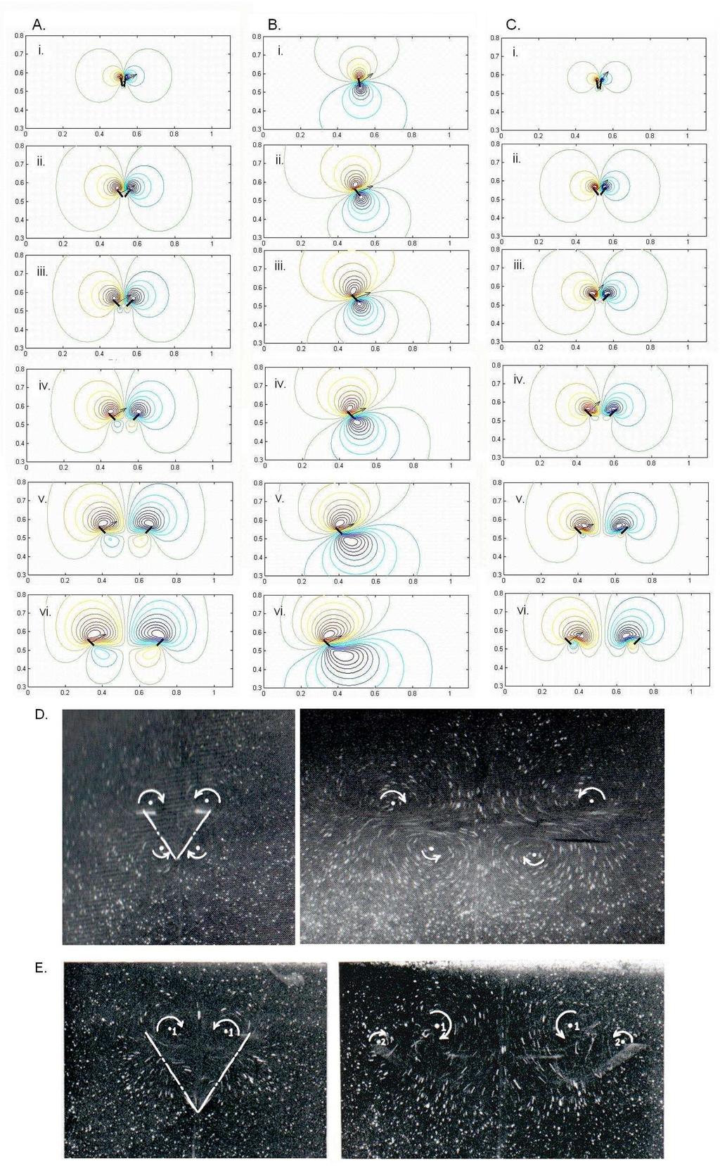
19 between the two-dimensional numerical simulations. Flow visualization and the corresponding streamline plots of the numerical simulations are shown at five stages during fling in Fig. 6. In all cases, two large leading edge vortices form and appear to remain attached to each wing during rotation. A second pair of small vortices also forms along the trailing edge. Results Fling In order to determine the effect of Reynolds number on the lift generated during fling, simulations using either one wing or two wings following the motion described in the Methods section were performed for Reynolds numbers ranging from 8 to 128. The Reynolds number was varied by changing the velocity of the wing and holding all other parameters constant. The streamlines of the flow around two wings and one wing at a Reynolds number of 8 and two wings at a Reynolds number of 128 performing the same fling motion are shown at six selected times in Fig. 7. The streamlines are curves which have the same direction at each point in the fluid as the instantaneous fluid velocity u(x, t). The density of the streamlines in each plot is proportional to the speed of the flow. For more details on how the plots were generated see Miller and Peskin (2004). Normalized force vectors at each -19-
20 point in time were also drawn on the wing to display the direction of the force that the fluid applies to the wing. In the two-winged case with Re = 8 (Fig. 7A), the streamlines of the flow during wing rotation are qualitatively similar to those described by Lighthill (1973), calculated numerically by Haussling (1979), and observed experimentally by Maxworthy (1979) as shown in Fig 7D. As the wings rotate apart along the trailing edge, two large leading edge vortices are formed on each wing (Fig. 7A i-iii). No trailing edge vortices are formed until the wings begin to translate apart. At the beginning of translation, two weak trailing edge vortices begin to form on each wing (Fig. 7A iii - iv). As the wings continue to translate away from each other, the attached trailing edge vortices grow in strength (Fig. 7A iv-vi ). The strengths of the trailing edge vortices, however, are much less than the strengths of the leading edge vortices throughout the entire stroke considered here. Fig. 7D shows flow visualization of fling and subsequent translation at a Reynolds number of about 32 given by Maxworthy (1979). Similar to the numerical results, two large leading edge vortices form during rotation, and two smaller trailing edge vortices form and grow during translation. Both sets of leading and trailing edge vortices do not appear to separate from the wing. The streamline plots at Reynolds numbers of 16 and 32 are similar to those described here. In the one-winged case with Re = 8, both a leading and a trailing edge vortex are formed at the beginning of rotation (Fig. 7B i - iii). This phenomenon is consistent with the principle of total vorticity conservation. Consider an infinite fluid domain with a finite -20-
21 number of immersed solids that are a finite distance apart. If the fluid and solid bodies are initially at rest, then the total vorticity in the system (including the solid bodies) must remain zero for all time. In this case, the leading and trailing edge vortices spin in opposite directions during rotation and translation. Since the wings are infinitely thin, we can consider vorticity only within the fluid domain, and the principle of vorticity conservation demands that leading and trailing edge vortices cancel so that the total vorticity in the system is zero. This implies that the leading and trailing edge vortices are of equal and opposite strength. During translation, these two vortices remain attached to the wing throughout the entire stroke (Fig. 7B iv-vi). This situation is markedly different from the two-winged case: leading and trailing edge vortices are formed during rotation in the one-winged case, while two leading edge vortices and no trailing edge vortices are formed in the two-winged case. During translation, leading and trailing edge vortices of equal strength are attached to the wing in the one-winged case, while a strong leading edge vortex and a weak trailing edge vortex form and remain attached to each wing in the two-winged case. At a Reynolds number of 128 (Fig. 7C), the aerodynamics during the two-winged fling differ from the corresponding cases at Reynolds numbers of 32 and below. At the beginning of the half stroke, two strong leading edge vortices are formed during wing rotation (Fig. 7C i-ii). As the wings translate apart, weak trailing edge vortices are formed and begin to grow (Fig. 7C iii-iv). Unlike the low Reynolds number case, the leading edge vortices are shed at the beginning of translation (Fig. 7C iv-v). During translation, a second pair of leading edge vortices are formed and begin to grow. This same -21-
22 phenomenon was observed by Maxworthy (1979) at higher Reynolds numbers (Fig 7E). Two large leading edge vortices (1) are formed during rotation. As translation begins, the pair of rotational leading edge vortices is shed, and a second pair of leading edge vortices (2) is formed. In the immersed boundary simulation, the trailing edge vortices are shed as translation continues (Fig. 7C v-vi). The alternate vortex shedding at higher Reynolds numbers corresponds to the formation of the von Karman street. It is important, however, to note that in three-dimensional insect flight at higher Reynolds numbers, alternate vortex shedding does not occur (Birch et al., 2004). Instead, the leading edge vortex remains attached to the wing and the trailing edge vortex is shed. Presumably, the leading edge vortex would remain attached to the wing during three-dimensional clap and fling at higher Reynolds numbers, generating larger lift coefficients for both the two- and onewinged cases. The lift coefficients as functions of dimensionless time (fraction of stroke) for the oneand two-winged cases at a Reynolds number of 8 are plotted in Fig. 8. The bar at the top of the graph shows the number of chord lengths traveled. The first peak in the lift coefficients corresponds to the large lift forces generated during wing rotation. The second peak in the lift coefficients corresponds to the period of translational acceleration. The average lift per wing generated during wing rotation in the two-winged case is about twice that generated in the one-winged case. In addition, the lift forces are about 70% greater in the two-winged case than in the one-winged case at the beginning of translation. Lift forces per wing in the two-winged case are on average about 35% higher than in the one-wing case during the entire 4.5 chord length translation. Another interesting -22-
23 phenomenon seen in the one-winged case is that lift is slow to develop over the first couple chord lengths of translation. This is most likely due to the Wagner effect in which the proximity of the trailing edge vortex to the wing transiently reduces the lift until it moves sufficiently downstream of the wing. This idea is supported by the fact that the phenomenon is not observed in the two-winged case where the trailing edge vortices are initially absent. Both one- and two-winged lift forces approach the same steady state lift at the end of translation. These force traces are very similar to those calculated by Sun and Yu (2003) at a Reynolds number of 17 using a similar two-winged fling motion. The wings in their simulation were 0.08 chord lengths apart at the beginning of the stroke, and the wings rotated apart at a faster angular velocity. The average lift coefficient over the entire 3 chord length half-stroke (rotation and translation) in their simulation was 2.4 for two wings and 1.0 for one wing. Lift coefficients for a range of Reynolds numbers are plotted as functions of dimensionless time for two-winged fling in Fig. 9. The first peak corresponds to the lift generated during wing rotation, and the second peak corresponds to the lift generated during translational acceleration. For Reynolds numbers of 32 and below, the different cases are similar. Lift coefficients decrease during translation as the trailing edge vortex grows. Lift is also enhanced for longer periods of time at lower Reynolds numbers (the relative difference in strength between the attached leading and trailing edge vortices persists longer for lower Reynolds numbers). The growth of the trailing edge vortex during translation and resulting drop in lift was also observed by Sun and Yu (2003) at a Reynolds number of 17. For Reynolds numbers of 64 and higher, the leading edge vortex -23-
24 is shed at the beginning of translation, and lift forces subsequently drop. Lift forces grow again as a new leading edge vortex is formed and the trailing edge vortex is shed. This may not be obvious in Fig. 9, but the growth in lift followed by force oscillations become apparent when longer periods of time are plotted. As stated earlier, the three-dimensional case of flight at higher Reynolds numbers does not involve oscillating lift forces since alternate vortex shedding does not occur. It is also important to note that the leading edge vortex is shed after about 1 chord length of travel. Other studies, including a twodimensional experiment (Dickinson and Gotz, 1993) and a two-dimensional numerical simulation (Wang et al., 2004), show that the separation of the leading edge vortex and subsequent lift drop does not occur until about chord lengths of travel. Maxworthy (1979) and these simulations show that the leading edge vortex is shed near the beginning of translation after fling at higher Reynolds numbers (~10 4 ). This suggests that the separation of the leading edge vortex from the wing could depend upon wingwing interactions and the kinematics of rotation. Lift coefficients for a range of Reynolds numbers are plotted as functions of dimensionless time for one-winged fling in Fig. 10. The first peak corresponds to the lift forces produced during wing rotation, and the second peak corresponds to the lift forces generated during translational acceleration. Lift coefficients for periods of rotation and acceleration are higher at lower Reynolds numbers. This phenomenon might be due to the larger effect of added mass at lower Reynolds numbers. As the Reynolds number decreases, the width of the boundary layer around the wing grows and the mass of the fluid 'entrained' by the wing is larger. Lift coefficients are also substantially lower at all -24-
25 times and for all Reynolds numbers considered when compared to the respective twowinged cases (note the difference in scales between Figs. 9 and 10). For Reynolds numbers of 64 and higher, lift begins to drop after about 2.5 chord lengths of travel during translation due to the separation of the leading edge vortex. Presumably, translational lift forces would be higher in three-dimensional flight since the leading edge vortices would not be shed. Drag coefficients for a range of Reynolds numbers are plotted as functions of dimensionless time for two-winged fling in Fig. 11. The first peak in each of the drag coefficient plots corresponds to the large drag forces produced as the two wings are rotated apart. The maximum drag coefficient produced during rotation increases significantly as the Reynolds number is decreased. The smaller second peak in drag coefficients corresponds to the forces generated during the translational acceleration of the wings at the beginning of the half-stroke. This translational drag coefficient also increases with decreasing Reynolds number, but the effect is substantially smaller than that produced during wing rotation. Drag coefficients for all Reynolds numbers gradually decrease during translation to steady values. Again, translational drag coefficients increase with decreasing Reynolds number. Drag coefficients for a range of Reynolds numbers are plotted as functions of dimensionless time for one-winged fling in Fig. 12. The first peak in the drag coefficients corresponds to the drag forces produced during the rotation of a single wing. These drag forces per wing are significantly smaller than those produced during rotation with two -25-
26 wings (note the difference in scales between Figs. 11 and 12). The second peak in the drag coefficient corresponds to the drag forces produced during the translational acceleration of the wing. After acceleration, the drag coefficients gradually decrease to steady state values. Similar to the two-winged case, drag coefficients during one-winged fling increase with decreasing Reynolds number. The average lift per wing generated during translation after a two-winged fling halfstroke divided by the average lift per wing generated during translation after a onewinged fling half-stroke are plotted for a range of Reynolds numbers in Fig. 13. The average lift coefficients per wing after fling were calculated as the average lift after translational acceleration and during the steady translation of the wing at a constant angle of attack ( fraction of the half-stroke). For a Reynolds numbers of 8, the average lift generated during a 4.5 chord translation after two-winged fling is on average 35% larger than the average lift generated during translation after one-winged fling. Lift enhancement provided by two-winged fling decreases with increasing Reynolds number. For a Reynolds number of 128, the average lift per wing produced during translation after two-winged fling is about equal to the average lift generated during translation following a one-winged fling. It is important to note that these ratios only consider the effect of lift enhancement after rotation and acceleration. The maximum drag coefficients produced during rotation for two-winged fling for a range of Reynolds numbers are plotted in Fig. 14. The drag coefficients produced during rotational fling sharply increase with decreasing Reynolds number. This same -26-
27 phenomenon is also true during all periods of rotation and acceleration. The Reynolds number effect is, however, most pronounced during fling. This relationship suggests that tiny insects must apply large forces to the fluid to turn and rotate their wings. Perhaps flexible wings and setal fringing reduce this Reynolds number effect. Clap and Fling The streamlines of the flow around two wings and around one wing performing a complete clap and fling motion at a Reynolds numbers of 8 (A and B) and around two wings performing a complete clap and fling stroke at a Reynolds number of 128 (C) are shown at eight points in time in Fig. 15. In the two-winged case, the wings accelerate from rest and move towards each other at a constant translational speed. At a Reynolds number of 8, leading and trailing edge vortices form and remain attached to each of the wings during the first half-stroke (Fig. 15A i-iii). As the wings near each other, they begin to rotate and clap together (Fig. 15 A iv v). During this rotation, the leading and trailing edge vortices are shed. The wings then rotate apart and translate away from each other during fling (Fig. 15A vi viii). This is similar to the previous case of simple fling, except that the wings are now translating through their wakes. During rotation (Fig. 15A vi), new leading edge vortices are formed on each wing, and no trailing edge vortices are formed initially. As the wings translate away from each other, they move back through their wakes, and weak trailing edge vortices are formed (Fig. 15A vii viii). In the case of one wing, a pair of leading and trailing edge vortices is formed during the initial translation (Fig. 15B i iii). These vortices are then shed during wing rotation (Fig. 15B iv-v). During the downstroke, a pair of large leading and trailing edge vortices is -27-
28 formed. This is different from the two-winged case where only two large leading edge vortices are formed initially. For Reynolds number of 128 (Fig. 15C), the leading edge vortices are formed and the trailing edge vortices are shed during the initial translation of the wing (Fig. 15C i-ii). The leading edge vortices begin to separate from the wing after a translation of about 2.5 chord lengths (Fig. 15C iii). Lift drops as the wings near each other and clap together (Fig. 15C iv-v). During this rotation of the wings, the vortices from the first half-stroke are shed. Next, the wings continue to rotate apart and then translate away from each other during fling (Fig. 15C v-vi). Similar to the previous case of a fling half-stroke, two large leading edge vortices are formed during rotation, and no trailing edge vortices are formed initially (Fig. 15C vi). As the wings translate away from each other, the leading edge vortices are shed (Fig. 15C vii), and new trailing edge vortices form and grow in strength. Later in the stroke, a second pair of leading edge vortices forms and grows in strength (Fig. 15C viii). Lift coefficients for a range of Reynolds numbers are plotted as functions of dimensionless time for two-winged fling in Fig. 16. The markers on the time axis denote the points in time that the streamline plots in Fig. 15A, C were drawn. The lift coefficients naturally divide into two patterns, lift coefficients for Reynolds numbers of 64 and above and lift coefficients for Reynolds numbers of 32 and below. -28-
29 The lift coefficients for Reynolds numbers of 32 and below are characterized by relatively constant forces during translation due to the attachment of the leading and trailing edge vortices. The first peak in the lift coefficient corresponds to the forces produced during wing acceleration at the beginning of the stroke (i). During constant translation, lift coefficients initially drop and then gradually increase as the wings approach each other (ii iii). Lift coefficients suddenly drop again when the wings decelerate and begin to rotate (iv). During this clap, lift forces increase and then drop again towards the end of rotation (iv v). During rotation at the beginning of the second half-stroke (fling), lift coefficients peak as two large leading edge vortices are formed (v vi). The next peak in lift (vi vii) corresponds to the lift generated during translational acceleration. These translational lift coefficients are larger than those produced during the first half-stroke. This lift enhancing effect is due to the asymmetry in the vortical field produced by the clap and fling motion. The lift coefficients for Reynolds numbers of 64 and above are characterized by unsteady lift forces due to vortex shedding. The initial peak in lift coefficients corresponds to the lift forces produced during the translational acceleration of the wings (i). During constant translation, the leading edge vortex begins to separate but lift does not drop significantly until a translation of about three chord lengths (ii iii). Lift then drops significantly as the two wings decelerate at the end of the upstroke and clap together (iv v). At the beginning of the second half-stroke, lift is enhanced when two large leading edge vortices are formed during rotation (f). As the wings begin to translate away from each other, the leading edge vortices are shed and trailing edge vortices grow (vi). Later during -29-
30 translation, the trailing edge vortices begin to separate from the wing, a new pair of leading edge vortices begins to grow, and the lift coefficient subsequently increases. This is consistent with the pattern of vortex shedding and growth visualized by Maxworthy (1979) at high Reynolds numbers. In Maxworthy s flow visualization, the initial pair of leading edge vortices is shed when translation begins, and a second pair of leading edge vortices begins to grow. Lift coefficients for a range of Reynolds numbers for one wing moving in a clap and fling motion are shown in Fig. 17. The initial peak in lift corresponds to the lift forces generated during wing acceleration from rest. During upstroke translation, lift coefficients generally increase with increasing Reynolds number. For higher Reynolds numbers, the lift forces grow during the first three chord lengths of translation (ii iii). The leading edge vortex then begins to separate from the wing, and the lift forces drop as the wing decelerates and begins to rotate (iv-v). During fling and wing rotation, lift coefficients are slightly higher at lower Reynolds numbers. During downstroke translation, lift drops for Reynolds numbers of 64 and above after a translation of about 2.5 chord lengths as the leading edge vortex is shed. Dickinson (1994) measured lift forces experimentally on a wing moving with a two-dimensional motion similar to the motion used in this simulation. The lift coefficients measured over time in each case are remarkably similar. Lift forces peak during rotation and acceleration, fall to values near 1.5 during the first chord lengths of translation, and drop to values near 1 as the leading edge vortex separates from the wing. -30-
31 Drag coefficients for a range of Reynolds numbers are plotted as functions of dimensionless time for two-winged fling in Fig. 18. The letter markers on the time axis denote the points in time when the streamline plots in Fig. 15 A, C were drawn. In general, drag coefficients increase with decreasing Reynolds number. The first peak in the drag coefficients corresponds to the drag forces generated during the translational acceleration of the wing (i). Drag coefficients remain relatively constant during the translational phase of the first half-stroke (i iii). The drag coefficients drop during wing deceleration, but sharply increase again when the wings are rotated (clapped) together (iv). At the beginning of the second half-stroke, the drag coefficients peak again as the wings are rotated apart (v vi). There is a smaller peak during translational acceleration (vi vii). Finally, the drag coefficients approach a steady state value as the wings translate apart vii viii). The Reynolds number differences in drag coefficients are most pronounced during wing rotation. Drag coefficients for a range of Reynolds numbers during one-winged clap and fling are shown in Figure 19. In general, drag coefficients are larger at lower Reynolds numbers throughout the entire stroke. In comparison to the two-winged case, drag coefficients per wing are lower throughout the stroke for the one-winged case at all Reynolds numbers. The differences between the one and two-winged cases are greatest during wing rotation (particularly during fling) and acceleration at lower Reynolds numbers. The drag coefficients over time in these simulations are also strikingly similar to those measured experimentally by Dickinson (1994) using one wing moving in a two-dimensional motion. -31-
32 Fig. 20 shows the average lift and drag coefficients generated during a fling half-stroke started from rest and a fling half-stroke that follows a clap half-stroke. The force coefficients were averaged over wing rotation and subsequent translation of about 3.5 chord lengths. For all Reynolds numbers considered, lift and drag coefficients were higher for fling half-strokes that followed clap half-strokes. This wake effect decreases with decreasing Reynolds number. Discussion The main result of this paper is that the lift enhancing effects of clap and fling are larger for lower Reynolds numbers than for higher Reynolds numbers. Not only are large lift forces generated during wing rotation, but they are also transiently enhanced during the translation of the wing following fling when compared to lift forces generated by one wing performing the same motion. In practice at low Reynolds numbers, the part of the translational phase during which lift is enhanced lasts long enough to comprise most or all of the actual wing motion. For Reynolds numbers of 64 and higher, clap and fling enhances lift during wing rotation, but does not enhance lift significantly during translation. For Reynolds numbers of 32 and below, lift is significantly enhanced following clap and fling when compared to the one-winged case. This lift enhancing effect increases with decreasing Reynolds number. Moreover, these Reynolds number differences in lift enhancement could explain why most, if not all, tiny insects have -32-
33 converged upon clap and fling, while the vast majority of larger insects do not use this mechanism. Another result of potential significance is that the relative drag forces required to rotate the wings apart during fling increase dramatically for lower Reynolds numbers. In these simulations, the wings begin fling at a distance of 1/6 chord lengths apart. In reality, the wings are pressed together, and it is reasonable to assume that the drag forces generated during fling would be even greater. Some of the difference between the higher and lower Reynolds number cases can be related to an aerodynamic transition observed in this Reynolds number range (Childress and Dudley, 2004; Vandenberghe et al., 2004; Miller and Peskin, 2004). For Reynolds numbers of 64 and above in three-dimensional strokes, lift is generated in part when an attached leading edge vortex is formed and a trailing edge vortex is shed during each wing stroke. This vortical asymmetry generates negative circulation around the wing and, consequently, creates positive lift. Lift is also produced similarly in two-dimensional simulations at higher Reynolds numbers. However, the leading edge vortex is only transiently attached to the wing. At these high Reynolds numbers, lift enhancement by clap and fling during translation is minimal (at least in two dimensions). For Reynolds numbers of 32 and below in two dimensions, leading and trailing edge vortices form and remain attached to the wing during each stroke. This vortical symmetry greatly reduces the circulation around the wing and the lift produced when compared to the threedimensional case of flight at higher Reynolds numbers. A recent study by Wu and Sun -33-
34 (2004) also suggests that lift is greatly reduced at these lower Reynolds numbers in three dimensions. During clap and fling, two large attached leading edge vortices are formed on each wing, and no trailing edge vortices are formed initially. When the wings begin to translate away from one another, two weak trailing edge vortices are formed on each wing and grow during translation. The leading edge vortices, however, are much stronger than the trailing edge vortices throughout the stroke. This vortical asymmetry produced by clap and fling recovers some of the lift lost from this transition. To understand the aerodynamic mechanism of lift generation, consider the case of fling diagramed in Fig. 21. The two wings were rotated apart along their trailing edges and are now translating away from each other along a horizontal plane. By convention, positive motion is defined from right to left so that the circulation around the left wing is negative and the lift is positive. During rotation, two large leading edge vortices (R n 1 and R p 1) of equal strength and opposite sign were formed and remain attached to the wing. During translation, two small trailing edge vortices of equal strength and opposite sign begin to form and grow in strength (R n 2 and R p 2). Let the rest of the fluid domain (R f ) be of negligible vorticity. Note that the subscript n denotes regions of negative (clockwise) vorticity, and p denotes regions of positive (counterclockwise) vorticity. In the following discussion, an Eulerian frame of reference will be used. The total lift acting on both wings can then be defined as follows using a general viscous aerodynamic theory developed by Wu (1981): F L d d d = ρ xω dx dy = ρ R x ω dx dy ρ f Rp 1+ Rp 2 x ω dx dy dt dt dt Rn 1+ Rn 2 (20) -34-
35 where ω is the absolute value of the vorticity. The vortices in each pair are convected in opposite directions with each wing as the wings are translated apart. In an Eulerian framework, the vortices defined by R n 1 and R p 2 move with negative velocity (the vortices are pulled leftward with the wing). The vortices defined by R p 1 and R n 2 move with positive velocity (the vortices are pulled rightward with the wing). The equation for total lift in this case can be rewritten as follows: F L = ρ ρ d dt d dt Rn 1 x ω dx dy Rn 2 x ω dx dy + + d dt d dt R p1 x ω dx dy Rp 2 x ω dx dy (21) This equation basically states that the total lift on both wings is proportional to the difference between the magnitude of the time rate of change of the first moment of vorticity associated with the leading edge vorticity and the time rate of change of the first moment of trailing edge vorticity. Therefore, vortical asymmetry produced by clap and fling will transiently enhance lift forces during translation. This work was supported by the National Science Foundation under Grant Number DMS
36 Bibliography BIRCH, J. M. AND DICKINSON, M. H. (2003). The influence of wing wake interactions on the production of aerodynamic forces in flapping flight. J. Exp. Biol. 206, BIRCH, J. M., DICKSON, W. B., AND DICKINSON, M. H. (2004). Force production and flow structure of the leading edge vortex on flapping wings at high and low Reynolds numbers. J. Exp. Biol. 207, CHILDRESS, S. AND DUDLEY, R. Transition from ciliary to flapping mode in a swimming mollusc: Flapping flight as a bifurcation in Re_omegsa. In publication, J. Fluid Mech. DICKINSON, M. H. and GÖTZ, K. G. (1993). Unsteady aerodynamic performance of model wings at low Reynolds numbers. J. exp. Biol. 174, 174. ELLINGTON, C. P. (1984). The aerodynamics of hovering insect flight. III. Kinematics. Phil. Trans. R. Soc. Lond. B 305, ELLINGTON, C. P. (1999). The novel aerodynamics of insect flight: Applications to micro-air vehicles. J. exp. Biol. 202, HAUSSLING, H. J. (1979). Boundary fitted coordinates for accurate numerical solution of multibody flow problems. J. Comp. Phys. 30, LIGHTHILL, M. J. (1973). On the Weis-Fogh mechanism of lift generation. J. Fluid Mech. 60, MAXWORTHY, T. (1979). Experiments on the Weis-Fogh mechanism of lift generation by insects in hovering flight. Part I. Dynamics of the fling. J. Fluid Mech. 93, MILLER, L. A., AND PESKIN, C. S. (2004). When vortices stick: An aerodynamic transition in tiny insect flight. J. Exp. Biol. 207, PESKIN, C. S. (2002). The immersed boundary method. Acta Numerica, 11, SRYGLEY, R. B. AND THOMAS, A. L. R. (2002). Unconventional lift-generating mechanisms in free-flying butterflies. Nature 420, SPEDDING, G. R. AND MAXWORTHY, T. (1986). The generation of circulation and lift in a rigid two-dimensional fling. J. Fluid Mech. 165,
37 SUN, M. AND YU, X. (2003). Flow around two airfoils performing fling and subsequent translation and translation and subsequent flap. Acta Mechanica Sinica 19, SUNADA, S., KAWACHI, K., WATANABE, I., AND AZUMA, A. (1993). Fundamental Analysis of three-dimensional near fling. J. Exp. Biol. 183, USHERWOOD, J. R. AND ELLINGTON, C. P. (2002a). The aerodynamics of revolving wings I. Model hawkmoth wings. J. Exp. Biol. 205, VANDENBERGHE, N., ZHANG, J. AND CHILDRESS, S. (2004). Symmetry breaking leads to forward flapping flight. To appear J. of Fluid Mechanics. WANG, Z. J., BIRCH, J. M., and DICKINSON, M. H. (2004). Unsteady forces and flows in low Reynolds number hovering flight: two-dimensional computations vs robotic wing experiments. J. Exp. Biol. 207: WEIS-FOGH, T. (1973). Quick estimates of flight fitness in hovering animals, including novel mechanisms for lift production. J. exp. Biol. 59, WEIS-FOGH, T. (1975). Unusual mechanisms for the generation of lift in flying animals. Scient. Am. 233, WU, J. C. (1981). Theory for aerodynamic force and moment in viscous flows. AIAA J. 19,
38 Fig. 1: Clap and fling (redrawn from Weis-Fogh, 1973). The three-dimensional motion (top) and the corresponding two-dimensional approximation (bottom). In this drawing, the insect flies with its body oriented almost vertically, and the wings move in a horizontal plane. At the beginning of the upstroke (A.), the wings move from the ventral to the dorsal side of the body, and rotate together about the leading edges. At the beginning of the downstroke (B.), the wings rotate apart about the trailing edges. Towards the end of rotation, the wings translate away from each other. -38-
39 Fig. 2: Dimensionless translational and angular velocities of the wing as a function of dimensionless time for one clap and fling stroke. The total motion was used for all clap and fling simulations. For fling simulations, the angular and translational velocities follow the second half of the graph. Note that the wing begins to rotate before the end of translation during the upstroke (first half stroke). Translation during the downstroke (second half stroke) also begins before wing rotation has ended. -39-
40 Fig. 3: Lift (blue) and drag (red) coefficients per wing during a two-winged fling halfstroke are plotted for two mesh widths. The coarser grid (dashed line) has a mesh width of about m (the same mesh width as the other simulations in this chapter), and the finer grid (solid line) has a mesh width of about m. The two grid sizes show good agreement with small deviations occurring during the rotational part of fling. -40-
41 Fig. 4: Lift and drag coefficients for four sinusoidal strokes. The green lines show the results of the immersed boundary simulation, the blue lines represent numerical data for a two-dimensional elliptic wing (Wang et al, 2004), and the red lines describe the experimental data for a three-dimensional model wing (Wang et al., 2004). In all cases, the leading edge vortex did not appear to separate during translation. The wing in each case flaps in a sinusoidal motion with Ф = 0, β = π/2, and A o / c= 2.8, as defined in Eqns. 17 and 18, at a Reynolds number of 75. This represents a 2.8 chord translation and a minimum angle of attack of
42 Phi (degrees) Time (seconds) Fig. 5: Rotational motion of two wings during fling and the corresponding lift forces. A) The dashed line represents the motion used in the clap and fling experiments of Spedding and Maxworthy (1986). The solid line represents the rotational motion of the wings used in the immersed boundary simulation. The motion used by Sun and Yu (2003) is nearly identical. B) The dotted line represents the lift forces measured over time in Spedding and Maxworthy's experiment at a Reynolds number of about The solid line represents the lift forces calculated by Sun and Yu at the same Reynolds number. The dashed line represents the scaled lift forces calculated over time in the immersed boundary simulation at a Reynolds number of
 Flow visualization of fling captured by Spedding and Maxworthy (1986) at a Reynolds number of abou about 3 10 3.")
43 Fig. 6: Flow visualization and streamline plots of rotational fling at six points in time. The wing motion used in each case is shown in Fig. 5A. A) Flow visualization of fling captured by Spedding and Maxworthy (1986) at a Reynolds number of abou about B) Streamline plots of fling calculated numerically for two rigid elliptic wings by Sun and Yu (2003) at a Reynolds number of about about C) Streamline plots of fling calculated from immersed boundary simulations at a Reynolds number of about 128. In all cases, two large leading vortices form and appear to remain attached to each wing during rotation. -43-
44 -44-
45 Fig. 7: Streamlines of fluid the flow around two wings (A) and one wing (B) at a Reynolds number of 8 and around two wings (C) at a Reynolds number of 128 for a fling half-stroke. The arrow on the left wing shows the direction of the normalized force acting on the wing at each time. The wings begin at an angle of attack of 90 and rotate about the trailing edge to an angle of attack of 45. A) During rotation, attached leading edge vortices are formed on each wing and no trailing edge vortices are formed (i iii). When translation begins, small attached trailing edge vortices begin to form (iii v). As the trailing edge vortices grow in size relative to the leading edge vortices, lift is reduced. The leading edge vortices, however, remain larger than the trailing edge vortices for most of the half-stroke (v vi). B) In the one wing case, attached leading edge and trailing edge vortices are formed during rotation (i iii). When translation begins, equally sized leading and trailing edge vortices are attached to the wing, creating substantially lower lift forces in comparison to the two-winged case (iii vi). C) At a Reynolds number of 128, attached leading edge vortices are formed on each wing and no trailing edge vortices are formed initially (i iii). When translation begins, however, the leading edge vortices are shed, and trailing edge vortices are formed (v - vi). The trailing edge vortex grows in size and is subsequently shed from the wing as a new leading edge vortex begins to form. D) Flow visualization of fling at a Reynolds number of 30 by Maxworthy (1979). Similar to case A, a pair of large leading edge vortices is formed and remains attached to the wing during rotation. A smaller pair of trailing edge vortices is formed and grows during translation. E) Flow visualization of fling at a Reynolds number of Similar to case C, a pair of large leading edge vortices (1) forms during rotation and is shed during translation. A new pair of leading edge vortices forms during translation (2). -45-
46 Fig. 8: Lift coefficients per wing at a Reynolds number of 8 are plotted as functions of time for the fling half-strokes shown in Fig. 7A. The bar at the top of the graph shows the number of chord lengths traveled. The first peak in the lift coefficients corresponds to the large lift forces generated during wing rotation. The second peak in the lift coefficients corresponds to the period of translational acceleration. The lift forces per wing are on average about 35% greater during translation after clap and fling than during the steady translation of a single wing with no clap and fling (this average was taken over the fraction of the stroke from 0.37 to 1, after rotation had finished). -46-

47 Fig. 9: Lift coefficients are plotted as functions of time for a two-winged clap and fling half-stroke. The bar at the top of the graph shows the number of chord lengths traveled. The angles of attack during pure translation were set to 45. Reynolds number was varied by changing the translational velocity of the wing from to 0.06 m/s. The first peak corresponds to the lift generated during wing rotation, and the second peak corresponds to the lift generated during translational acceleration. The lift enhancing mechanisms of fling decrease with increasing Reynolds number. For Reynolds numbers of 32 and below, lift coefficients decrease during translation after fling as the trailing edge vortex grows in strength. For Reynolds numbers of 64 and above, lift coefficients fall as the leading edge vortices separate from the wings. -47-
48 Fig. 10: Lift coefficients are plotted as functions of time for a one-winged fling halfstroke. The angle of attack during pure translation was set to 45. The Reynolds number was varied by changing the translational velocity of the wing from to 0.06 m/s. The first peak in lift corresponds to the lift forces generated during wing rotation. The second peak corresponds to the lift forces generated during translational acceleration. For Reynolds numbers of 64 and above, lift coefficients fall as the leading edge vortices separate from the wings. -48-
49 Fig. 11: Drag coefficients are plotted as functions of time for a two-winged fling halfstroke. The angles of attack during pure translation were set to 45. Reynolds number was varied by changing the translational velocity of the wing from to 0.06 m/s. The first large peak corresponds to drag generated during wing rotation. The second smaller peak corresponds to drag forces generated during translational acceleration. Drag coefficients increase with decreasing Reynolds number. This inverse relationship is particularly significant during the initial wing rotation. -49-

50 Fig. 12: Drag coefficients plotted as functions of time for a one-winged fling half-stroke. The angles of attack during pure translation were set to 45. Reynolds number was varied by changing the translational velocity of the wing from to 0.06 m/s. The first peak corresponds to the drag forces generated during translational acceleration. Note that the drag forces per wing generated during rotation in the one-winged case are significantly smaller than those generated per wing in the two-winged case (see Fig. 11). In general, drag coefficients increase with decreasing Reynolds number. -50-
51 Fig. 13: The average lift coefficients per wing during translation following two-winged fling divided by the corresponding average lift coefficients for one-winged fling plotted against Reynolds number. The average lift coefficients following fling were calculated as the average lift coefficients generated after rotation and translational acceleration and during translation at a constant angle of attack. This value decreases with increasing Reynolds number, suggesting that the lift enhancing effects of clap and fling are more significant at lower Reynolds numbers. -51-
52 Fig. 14: The maximum drag coefficient during the rotation of the wings at the beginning of fling plotted against the Reynolds number. The drag coefficient significantly increases for decreasing Reynolds number. This result suggests that relatively large forces are needed for tiny insects to rotate their wings and perform a fling -52-
 During translation, leading and trailing edge vortices form and remain attached to the wing (i iii).")
53 Fig. 15: Streamlines of fluid flow around two wings (A) and around one wing (B) during a full clap and fling stroke at a Reynolds number of 8 and around two wings at a Reynolds number of 128 (C). The arrow on the left wing shows the direction of the normalized force acting on the wing. A) During translation, leading and trailing edge vortices form and remain attached to the wing (i iii). During clap, the wings rotate together at the end of translation (iv v). At this time, the leading and trailing edge vortices are shed. During fling, the wings rotate apart forming two new leading edge vortices (vi). Towards the end of rotation, the wings are translated apart at a constant angle of attack and speed (vi viii). During translation, the leading edge vortices remain attached to the wing, and weak trailing edge vortices are formed. B) Large leading and trailing edge vortices are formed during the initial translation of the wing (i iii). This pair of vortices are shed during rotation (iv v), and a new pair of leading and trailing -53-
54 edge vortices are formed during the subsequent translation (vi viii). Note that in the two winged case, no trailing edge vortices are formed during wing rotation, and much smaller trailing edge vortices are formed during the subsequent translation. C) At a Reynolds number of 128, leading edge vortices are formed and the trailing edge vortices are shed (i - iii). After a translation of about 2.5 chord lengths, the leading edge vortices begin to separate from the wings (iii). During clap, the wings rotate together at the end of translation (iv v). At this time, the leading and trailing edge vortices are shed. During fling, the wings rotate apart. Two large leading edge vortices are formed, and no trailing edge vortices are formed initially (v vi). Towards the end of rotation, the wings are translated away from each other and the pair of leading edge vortices formed during rotation is shed, and a second pair of leading edge vortices begins to form near the end of translation (vi-viii). -54-

55 Fig. 16: Lift coefficients are plotted as functions of time for a two-winged clap and fling stroke. The angle of attack during pure translation was set to 45. The Reynolds number was varied by changing the translational velocity of the wing from to 0.06 m/s. In general, lift coefficients were larger at higher Reynolds numbers during the initial upstroke. Lift coefficients, however, were smaller at higher Reynolds numbers during fling and subsequent translation. For Reynolds numbers of 64 and higher, lift coefficients peak during translational acceleration and rotation. Lift coefficients drop when the leading edge vortices separate from the wing (vii viii). For Reynolds numbers of 32 and below, lift coefficients also peak during translational acceleration and rotation. Lift coefficients are relatively constant during translation in the first half-stroke (i iii). Lift coefficients are transiently augmented during translation after fling (vi viii). -55-
56 Fig. 17: Lift coefficients as functions of time for a one wing moving with the same clap and fling motion as shown in Fig. 16. The angle of attack during pure translation was set to 45. The Reynolds number was varied by changing the translational velocity of the wing from to 0.06 m/s. In general, lift coefficients increase with Reynolds number. The lift forces generated during the initial upstroke are very similar to those shown in the two-winged case (i iii). During fling, lift coefficients during rotation and the subsequent translation (vi viii) are significantly less than the two-winged case for Reynolds numbers of 32 and below. -56-
57 Fig. 18: Drag coefficients are plotted as functions of time for a two-winged clap and fling stroke. The angle of attack during pure translation was set to 45. The Reynolds number was varied by changing the translational velocity of the wing from to 0.06 m/s. In general, drag coefficients are larger for lower Reynolds numbers. This inverse relationship is most significant during periods of wing rotation (iv vi). In general, drag forces peak during periods of acceleration and rotation and remain relatively constant during periods of pure translation. -57-

58 Fig. 19: Drag coefficients for one-winged fling plotted as functions of time for a range of Reynolds numbers. The angle of attack during pure translation was set to 45. In general, drag coefficients are smaller for higher Reynolds numbers. In comparison to the twowinged case, drag coefficients are significantly lower during 'clap' (the end of the upstroke) for all Reynolds numbers. During wing rotation at the beginning of the downstroke, drag coefficients are substantially lower than the two-winged case for all Reynolds numbers. The difference between the one and two-winged case is greatest at lower Reynolds numbers. -58-
59 Fig. 20: The average lift and drag coefficients generated during fling for an entire fling half-stroke following a clap half-stoke and for an entire fling half-stroke started from rest as a function of the Reynolds number. Force coefficients were averaged during wing rotation and a subsequent translation of about 3.5 chord lengths. Average lift coefficients increase slightly with decreasing Reynolds number. Average drag coefficients increase significantly as the Reynolds number is lowered. Force coefficients are higher for fling half-strokes that follow clap half-strokes as the wings move back through their wakes. This wake capture effect decreases with decreasing Reynolds number. -59-

60 Fig. 21: Regions of positive and negative vorticity during the translation of two wings following clap and fling. R n 1 and R n 2 denote regions of negative vorticity, R p 1 and R p 2 denote regions of positive vorticity. The two wings are initially clapped together and rotate apart along their trailing edges. This rotation creates two large leading edge vortices. Towards the end of rotation, the wings begin to translate apart. During translation, two weak leading edge vortices begin to form. In this diagram, the wings are moving away from each other at a constant speed and angle of attack. The leading edge vortices (denoted by R n 1 and R p 1) are stronger than the trailing edge vortices (denoted by R n 2 and R p 2). This vortical asymmetry results in larger lift forces than in the symmetrical case without fling. -60-
A computational fluid dynamics of clap and fling in the smallest insects
 The Journal of Experimental Biology 8, 95- Published by The Company of Biologists 5 doi:.4/jeb.376 95 A computational fluid dynamics of clap and fling in the smallest insects Laura A. Miller, * and Charles
When vortices stick: an aerodynamic transition in tiny insect flight
 The Journal of Experimental Biology 7, 7-88 Published by The Company of Biologists 4 doi:.4/jeb.8 7 When vortices stick: an aerodynamic transition in tiny insect flight Laura A. Miller* and Charles S.
Many of the smallest flying insects clap their wings together at the end of each upstroke
 DRAFT Miller, L. A. and Peskin, C. S. Title: Flexible clap and fling in tiny insect flight. Abstract Many of the smallest flying insects clap their wings together at the end of each upstroke and fling
Flexible clap and fling in tiny insect flight
 376 The Journal of Experimental Biology, 376-39 Published by The Company of Biologists 9 doi:./jeb.866 Flexible clap and fling in tiny insect flight Laura A. Miller* and Charles S. Peskin Department of
ABSTRACT. travels through the wing reducing the drag forces generated. When the wings are in
 ABSTRACT Tiny insects use a process called clap and fling to augment the lift forces generated during flight. The one disadvantage to using this method is the drag forces created when the wings fling apart
Two-Dimensional Aerodynamic Models of Insect Flight for Robotic Flapping Wing Mechanisms of Maximum Efficiency
 Journal of Bionic Engineering 5 (2008) 1 11 Two-Dimensional Aerodynamic Models of Insect Flight for Robotic Flapping Wing Mechanisms of Maximum Efficiency Thien-Tong Nguyen 1, Doyoung Byun 2 1. Department
Unsteady aerodynamic forces of a flapping wing
 The Journal of Experimental Biology 7, 37-5 Published by The Company of Biologists 4 doi:.4/jeb.868 37 Unsteady aerodynamic forces of a flapping wing Jiang Hao Wu and Mao Sun* Institute of Fluid Mechanics,
Lift Enhancement by Dynamically Changing Wingspan. in Forward Flapping Flight (09/10/2013)
") Lift Enhancement by Dynamically Changing Wingspan in Forward Flapping Flight Shizhao Wang 1, Xing Zhang 1, Guowei He 1a), ianshu Liu 2,1 (09/10/2013) 1 he State Key Laboratory of Nonlinear Mechanics, Institute
Lift Enhancement by Dynamically Changing Wingspan in Forward Flapping Flight Shizhao Wang 1, Xing Zhang 1, Guowei He 1a), ianshu Liu 2,1 (09/10/2013) 1 he State Key Laboratory of Nonlinear Mechanics, Institute
Fundamentals of Fluid Dynamics: Ideal Flow Theory & Basic Aerodynamics
 Fundamentals of Fluid Dynamics: Ideal Flow Theory & Basic Aerodynamics Introductory Course on Multiphysics Modelling TOMASZ G. ZIELIŃSKI (after: D.J. ACHESON s Elementary Fluid Dynamics ) bluebox.ippt.pan.pl/
Computational Analysis of Hovering Hummingbird Flight
 Computational Analysis of Hovering Hummingbird Flight Zongxian Liang 1 and Haibo Dong 2 Department of Mechanical & Materials Engineering, Wright State University, Dayton, OH 45435 Mingjun Wei 3 Department
A flow control mechanism in wing flapping with stroke asymmetry during insect forward flight
 Acta Mech Sinica (2005) 21, 218 227 DOI 10.1007/s10409-005-0032-z RESEARCH PAPER Yongliang Yu Binggang Tong A flow control mechanism in wing flapping with stroke asymmetry during insect forward flight
Computational Analysis of Hovering Hummingbird Flight
 48th AIAA Aerospace Sciences Meeting Including the New Horizons Forum and Aerospace Exposition 4-7 January 2010, Orlando, Florida AIAA 2010-555 Computational Analysis of Hovering Hummingbird Flight Zongxian
NUMERICAL SIMULATION OF SELF-PROPELLED FLYING OF A THREE-DIMENSIONAL BIRD WITH FLAPPING WINGS
 NUMERICAL SIMULATION OF SELF-PROPELLED FLYING OF A THREE-DIMENSIONAL BIRD WITH FLAPPING WINGS WU Chui-Jie, ZHU Lin-Lin State Key Laboratory of Structural Analysis for Industrial Equipment, School of Aeronautics
Dynamic flight stability of a hovering bumblebee
 The Journal of Experimental iology 28, 447-459 Published by The Company of iologists 25 doi:1.1242/jeb.147 447 Dynamic flight stability of a hovering bumblebee Mao Sun* and Yan Xiong Institute of Fluid
Dynamic pitching of an elastic rectangular wing in hovering motion
 Under consideration for publication in J. Fluid Mech. Dynamic pitching of an elastic rectangular wing in hovering motion Hu Dai, Haoxiang Luo, and James F. Doyle 2 Department of Mechanical Engineering,
SENSITIVITY ANALYSIS OF THE FACTORS AFFECTING FORCE GENERATION BY WING FLAPPING MOTION
 Proceedings of the ASME 2013 International Mechanical Engineering Congress and Exposition IMECE2013 November 15-21, 2013, San Diego, California, USA IMECE2013-65472 SENSITIVITY ANALYSIS OF THE FACTORS
RESEARCH ARTICLE Aerodynamic effects of corrugation in flapping insect wings in hovering flight
 3 The Journal of Experimental iology, 3-. Published by The Company of iologists Ltd doi:./jeb.6375 RESERCH RTIE erodynamic effects of corrugation in flapping insect wings in hovering flight Xue Guang Meng*,
Analysis of a Hinge-Connected Flapping Plate with an Implemented Torsional Spring Model
 Analysis of a Hinge-Connected Flapping Plate with an Implemented Torsional Spring Model Zach Gaston 1, Hui Wan 2 and Haibo Dong 3 Department of Mechanical & Materials Engineering, Wright State University,
THE CONTROL OF FLIGHT FORCE BY A FLAPPING WING: LIFT AND DRAG PRODUCTION
 The Journal of Experimental Biology 24, 2672626 (2) Printed in Great Britain The Company of Biologists Limited 2 JEB34 267 THE CONTROL OF FLIGHT FORCE BY A FLAPPING WING: LIFT AND DRAG PRODUCTION SANJAY
Unsteady aerodynamics of fluttering and tumbling plates
 J. Fluid Mech. (25), vol. 541, pp. 65 9. c 25 Cambridge University Press doi:1.117/s221125594x Printed in the United Kingdom 65 Unsteady aerodynamics of fluttering and tumbling plates By A. ANDERSEN 1,
Lift and power requirements of hovering flight in Drosophila virilis
 The Journal of Experimental Biology 5, 37 () Printed in Great Britain The ompany of Biologists Limited JEB6 3 Lift and power requirements of hovering flight in Drosophila virilis Mao Sun* and Jian Tang
FUNDAMENTAL ANALYSIS OF THREE-DIMENSIONAL NEAR FLING
 J. exp. Biol. 83, 27 248 (993) Printed in Great Britain The Company of Biologists Limited 993 27 FUNDAMENTAL ANALYSIS OF THREE-DIMENSIONAL NEAR FLING SHIGERU SUNADA Exploratory Research for Advanced Technology,
Fluid Dynamics Exercises and questions for the course
 Fluid Dynamics Exercises and questions for the course January 15, 2014 A two dimensional flow field characterised by the following velocity components in polar coordinates is called a free vortex: u r
Dynamic flight stability of a hovering model insect: lateral motion
 Acta Mech Sin (010) 6:175 190 DOI 10.1007/s10409-009-00-1 RESEARCH PAPER Dynamic flight stability of a hovering model insect: lateral motion Yanlai Zhang Mao Sun Received: 18 May 009 / Revised: 5 August
Clap and Fling Mechanism with Interacting Porous Wings in Tiny Insect Flight
 First posted online on 4 September 2014 as 10.1242/jeb.084897 J Exp Biol Advance Access Online the most Articles. recent version First at posted http://jeb.biologists.org/lookup/doi/10.1242/jeb.084897
Numerical Analysis of Unsteady Viscous Flow through a Weis-Fogh-Type Water Turbine
 International Conference on Emerging Trends in Computer and Image Processing (ICETCIP'014) Dec. 15-16, 014 Pattaya (Thailand) Numerical Analysis of Unsteady Viscous Flow through a Weis-Fogh-Type Water
DISSECTING INSECT FLIGHT
 Annu. Rev. Fluid Mech. 2005. 37:183 210 doi: 10.1146/annurev.fluid.36.050802.121940 Copyright c 2005 by Annual Reviews. All rights reserved DISSECTING INSECT FLIGHT Z. Jane Wang Theoretical and Applied
Wing Kinematics in a Hovering Dronefly Minimize Power Expenditure
 Wing Kinematics in a Hovering Dronefly Minimize Power Expenditure Authors: J. H. Wu, and M. Sun Source: Journal of Insect Science, 14(159) : 1-8 Published By: Entomological Society of America URL: https://doi.org/10.1093/jisesa/ieu021
Masters in Mechanical Engineering. Problems of incompressible viscous flow. 2µ dx y(y h)+ U h y 0 < y < h,
+ U h y 0 < y < h,") Masters in Mechanical Engineering Problems of incompressible viscous flow 1. Consider the laminar Couette flow between two infinite flat plates (lower plate (y = 0) with no velocity and top plate (y =
Masters in Mechanical Engineering Problems of incompressible viscous flow 1. Consider the laminar Couette flow between two infinite flat plates (lower plate (y = 0) with no velocity and top plate (y =
A fundamental study of the flow past a circular cylinder using Abaqus/CFD
 A fundamental study of the flow past a circular cylinder using Abaqus/CFD Masami Sato, and Takaya Kobayashi Mechanical Design & Analysis Corporation Abstract: The latest release of Abaqus version 6.10
1. Fluid Dynamics Around Airfoils
 1. Fluid Dynamics Around Airfoils Two-dimensional flow around a streamlined shape Foces on an airfoil Distribution of pressue coefficient over an airfoil The variation of the lift coefficient with the
Fig. 1. Bending-Torsion Foil Flutter
 27 TH INTERNATIONAL CONGRESS OF THE AERONAUTICAL SCIENCES EXTRACTING POWER IN JET STREAMS: PUSHING THE PERFORMANCE OF FLAPPING WING TECHNOLOGY M.F. Platzer*, M.A. Ashraf**, J. Young**, and J.C.S. Lai**
Mestrado Integrado em Engenharia Mecânica Aerodynamics 1 st Semester 2012/13
 Mestrado Integrado em Engenharia Mecânica Aerodynamics 1 st Semester 212/13 Exam 2ª época, 2 February 213 Name : Time : 8: Number: Duration : 3 hours 1 st Part : No textbooks/notes allowed 2 nd Part :
Aeroelastic Analysis Of Membrane Wings
 Aeroelastic Analysis Of Membrane Wings Soumitra P. Banerjee and Mayuresh J. Patil Virginia Polytechnic Institute and State University, Blacksburg, Virginia 46-3 The physics of flapping is very important
Masters in Mechanical Engineering Aerodynamics 1 st Semester 2015/16
 Masters in Mechanical Engineering Aerodynamics st Semester 05/6 Exam st season, 8 January 06 Name : Time : 8:30 Number: Duration : 3 hours st Part : No textbooks/notes allowed nd Part : Textbooks allowed
Numerical Investigation of Thermal Performance in Cross Flow Around Square Array of Circular Cylinders
 Numerical Investigation of Thermal Performance in Cross Flow Around Square Array of Circular Cylinders A. Jugal M. Panchal, B. A M Lakdawala 2 A. M. Tech student, Mechanical Engineering Department, Institute
Analysis of transitions between fluttering, tumbling and steady descent of falling cards
 J. Fluid Mech. (25), vol. 541, pp. 91 14. c 25 Cambridge University Press doi:1.117/s2211255847 Printed in the United Kingdom 91 Analysis of transitions between fluttering, tumbling and steady descent
Unsteady Flow and Aerodynamic Effect of a Dynamic Trailing-Edge Flap in Flapping Flight
 Unsteady Flow and Aerodynamic Effect of a Dynamic Trailing-Edge Flap in Flapping Flight A Thesis Presented to the faculty of the School of Engineering and Applied Science University of Virginia In Partial
We are IntechOpen, the world s leading publisher of Open Access books Built by scientists, for scientists. International authors and editors
 We are IntechOpen, the world s leading publisher of Open Access books Built by scientists, for scientists 3,800 116,000 120M Open access books available International authors and editors Downloads Our
Vortex wake and energy transitions of an oscillating cylinder at low Reynolds number
 ANZIAM J. 46 (E) ppc181 C195, 2005 C181 Vortex wake and energy transitions of an oscillating cylinder at low Reynolds number B. Stewart J. Leontini K. Hourigan M. C. Thompson (Received 25 October 2004,
The wings and the body shape of Manduca sexta and Agrius convolvuli are compared in
 1 Wing and body shape of Manduca sexta and Agrius convolvuli The wings and the body shape of Manduca sexta and Agrius convolvuli are compared in terms of the aspect ratio of forewing AR fw (wing length
3.1 Definition Physical meaning Streamfunction and vorticity The Rankine vortex Circulation...
 Chapter 3 Vorticity Contents 3.1 Definition.................................. 19 3.2 Physical meaning............................. 19 3.3 Streamfunction and vorticity...................... 21 3.4 The Rankine
Clap and fling mechanism with interacting porous wings in tiny insect flight
 14. Published by The Company of iologists Ltd (14) 17, 3898-399 doi:1.14/jeb.84897 RESERCH RTICLE Clap and fling mechanism with interacting porous wings in tiny insect flight rvind Santhanakrishnan 1,
ABSTRACT PARAMETRIC INVESTIGATIONS INTO FLUID-STRUCTURE INTERACTIONS IN HOVERING FLAPPING FLIGHT. Jesse Maxwell, 2013
 ABSTRACT Title of Thesis: PARAMETRIC INVESTIGATIONS INTO FLUID-STRUCTURE INTERACTIONS IN HOVERING FLAPPING FLIGHT Jesse Maxwell, 2013 Thesis Directed By: Professor Balakumar Balachandran Department of
NUMERICAL SIMULATION OF THE FLOW AROUND A SQUARE CYLINDER USING THE VORTEX METHOD
 NUMERICAL SIMULATION OF THE FLOW AROUND A SQUARE CYLINDER USING THE VORTEX METHOD V. G. Guedes a, G. C. R. Bodstein b, and M. H. Hirata c a Centro de Pesquisas de Energia Elétrica Departamento de Tecnologias
Vortex structures in the wake of a buoyant tethered cylinder at moderate to high reduced velocities
 European Journal of Mechanics B/Fluids 23 (2004) 127 135 Vortex structures in the wake of a buoyant tethered cylinder at moderate to high reduced velocities K. Ryan, M.C. Thompson, K. Hourigan Fluids Laboratory
Numerical Investigation of the Fluid Flow around and Past a Circular Cylinder by Ansys Simulation
 , pp.49-58 http://dx.doi.org/10.1457/ijast.016.9.06 Numerical Investigation of the Fluid Flow around and Past a Circular Cylinder by Ansys Simulation Mojtaba Daneshi Department of Mechanical Engineering,
APS Flapping flight from flexible wings : tuning of wing stiffness for flight? Tom Daniel, Stacey Combes,, & Sanjay Sane
 APS 2004 Flapping flight from flexible wings : tuning of wing stiffness for flight? Tom Daniel, Stacey Combes,, & Sanjay Sane CNS SENSORY INPUT MOTOR OUTPUT FLIGHT MUSCLES FORCE, STRAIN WING HINGE How
FLUID MECHANICS. Atmosphere, Ocean. Aerodynamics. Energy conversion. Transport of heat/other. Numerous industrial processes
 SG2214 Anders Dahlkild Luca Brandt FLUID MECHANICS : SG2214 Course requirements (7.5 cr.) INL 1 (3 cr.) 3 sets of home work problems (for 10 p. on written exam) 1 laboration TEN1 (4.5 cr.) 1 written exam
Math 575-Lecture Failure of ideal fluid; Vanishing viscosity. 1.1 Drawbacks of ideal fluids. 1.2 vanishing viscosity
 Math 575-Lecture 12 In this lecture, we investigate why the ideal fluid is not suitable sometimes; try to explain why the negative circulation appears in the airfoil and introduce the vortical wake to
Fluid Dynamics: Theory, Computation, and Numerical Simulation Second Edition
 Fluid Dynamics: Theory, Computation, and Numerical Simulation Second Edition C. Pozrikidis m Springer Contents Preface v 1 Introduction to Kinematics 1 1.1 Fluids and solids 1 1.2 Fluid parcels and flow
(This is a sample cover image for this issue. The actual cover is not yet available at this time.)
") (This is a sample cover image for this issue. The actual cover is not yet available at this time.) This is an open access article which appeared in a ournal published by Elsevier. This article is free
(This is a sample cover image for this issue. The actual cover is not yet available at this time.) This is an open access article which appeared in a ournal published by Elsevier. This article is free
Given the water behaves as shown above, which direction will the cylinder rotate?
 water stream fixed but free to rotate Given the water behaves as shown above, which direction will the cylinder rotate? ) Clockwise 2) Counter-clockwise 3) Not enough information F y U 0 U F x V=0 V=0
Numerical Investigation of Vortex Induced Vibration of Two Cylinders in Side by Side Arrangement
 Numerical Investigation of Vortex Induced Vibration of Two Cylinders in Side by Side Arrangement Sourav Kumar Kar a, 1,, Harshit Mishra a, 2, Rishitosh Ranjan b, 3 Undergraduate Student a, Assitant Proffessor
Turbulent Boundary Layers & Turbulence Models. Lecture 09
 Turbulent Boundary Layers & Turbulence Models Lecture 09 The turbulent boundary layer In turbulent flow, the boundary layer is defined as the thin region on the surface of a body in which viscous effects
Aerodynamic force analysis in high Reynolds number flows by Lamb vector integration
 Aerodynamic force analysis in high Reynolds number flows by Lamb vector integration Claudio Marongiu, Renato Tognaccini 2 CIRA, Italian Center for Aerospace Research, Capua (CE), Italy E-mail: c.marongiu@cira.it
UNIT 4 FORCES ON IMMERSED BODIES. Lecture-01
 1 UNIT 4 FORCES ON IMMERSED BODIES Lecture-01 Forces on immersed bodies When a body is immersed in a real fluid, which is flowing at a uniform velocity U, the fluid will exert a force on the body. The
COURSE ON VEHICLE AERODYNAMICS Prof. Tamás Lajos University of Rome La Sapienza 1999
 COURSE ON VEHICLE AERODYNAMICS Prof. Tamás Lajos University of Rome La Sapienza 1999 1. Introduction Subject of the course: basics of vehicle aerodynamics ground vehicle aerodynamics examples in car, bus,
Fluid transport and coherent structures of translating and flapping wings
 Manuscript submitted to Chaos for special issue on Lagrangian Coherent Structures Fluid transport and coherent structures of translating and flapping wings Jeff D. Eldredge and Kwitae Chong Mechanical
Modeling of Instantaneous Passive Pitch of Flexible Flapping Wings
 Fluid Dynamics and Co-located Conferences June 24-27, 2013, San Diego, CA 43rd Fluid Dynamics Conference AIAA 2013-2469 Modeling of Instantaneous Passive Pitch of Flexible Flapping Wings Chang-kwon Kang
Unsteady forces on an accelerating plate and application to hovering insect flight
 J. Fluid Mech. 24), vol. 59, pp. 2. c 24 Cambridge University Press DOI:.7/S2224882 Printed in the United Kingdom Unsteady forces on an accelerating plate and application to hovering insect flight By D.
ROLE OF THE VERTICAL PRESSURE GRADIENT IN WAVE BOUNDARY LAYERS
 ROLE OF THE VERTICAL PRESSURE GRADIENT IN WAVE BOUNDARY LAYERS Karsten Lindegård Jensen 1, B. Mutlu Sumer 1, Giovanna Vittori 2 and Paolo Blondeaux 2 The pressure field in an oscillatory boundary layer
The aerodynamic effects of wing rotation and a revised quasi-steady model of flapping flight
 The Journal of Experimental Biology 5, 87 96 () Printed in Great Britain The Company of Biologists Limited JEB396 87 The aerodynamic effects of wing rotation and a revised quasi-steady model of flapping
ν δ - 1 -
 ν δ - 1 - δ ν ν δ ν ν - 2 - ρ δ ρ θ θ θ δ τ ρ θ δ δ θ δ δ δ δ τ μ δ μ δ ν δ δ δ - 3 - τ ρ δ ρ δ ρ δ δ δ δ δ δ δ δ δ δ δ - 4 - ρ μ ρ μ ρ ρ μ μ ρ - 5 - ρ τ μ τ μ ρ δ δ δ - 6 - τ ρ μ τ ρ μ ρ δ θ θ δ θ - 7
VORTEX SHEDDING PATTERNS IN FLOW PAST INLINE OSCILLATING ELLIPTICAL CYLINDERS
 THERMAL SCIENCE, Year 2012, Vol. 16, No. 5, pp. 1395-1399 1395 VORTEX SHEDDING PATTERNS IN FLOW PAST INLINE OSCILLATING ELLIPTICAL CYLINDERS by Li-Zhong HUANG a* and De-Ming NIE b a State Key Laboratory
V (r,t) = i ˆ u( x, y,z,t) + ˆ j v( x, y,z,t) + k ˆ w( x, y, z,t)
 = i ˆ u( x, y,z,t) + ˆ j v( x, y,z,t) + k ˆ w( x, y, z,t)") IV. DIFFERENTIAL RELATIONS FOR A FLUID PARTICLE This chapter presents the development and application of the basic differential equations of fluid motion. Simplifications in the general equations and common
IV. DIFFERENTIAL RELATIONS FOR A FLUID PARTICLE This chapter presents the development and application of the basic differential equations of fluid motion. Simplifications in the general equations and common
FLUID MECHANICS. Chapter 9 Flow over Immersed Bodies
 FLUID MECHANICS Chapter 9 Flow over Immersed Bodies CHAP 9. FLOW OVER IMMERSED BODIES CONTENTS 9.1 General External Flow Characteristics 9.3 Drag 9.4 Lift 9.1 General External Flow Characteristics 9.1.1
Vortex Dynamics in Near Wake of a Hovering Hawkmoth
 46th AIAA Aerospace Sciences Meeting and Exhibit 7-1 January 28, Reno, Nevada AIAA 28-583 Vortex Dynamics in Near Wake of a Hovering Hawkmoth Hikaru Aono 1 Graduate School of Science and Technology, Chiba
Detailed Outline, M E 521: Foundations of Fluid Mechanics I
 Detailed Outline, M E 521: Foundations of Fluid Mechanics I I. Introduction and Review A. Notation 1. Vectors 2. Second-order tensors 3. Volume vs. velocity 4. Del operator B. Chapter 1: Review of Basic
Detailed Outline, M E 320 Fluid Flow, Spring Semester 2015
 Detailed Outline, M E 320 Fluid Flow, Spring Semester 2015 I. Introduction (Chapters 1 and 2) A. What is Fluid Mechanics? 1. What is a fluid? 2. What is mechanics? B. Classification of Fluid Flows 1. Viscous
Self-Excited Vibration in Hydraulic Ball Check Valve
 Self-Excited Vibration in Hydraulic Ball Check Valve L. Grinis, V. Haslavsky, U. Tzadka Abstract This paper describes an experimental, theoretical model and numerical study of concentrated vortex flow
Math background. Physics. Simulation. Related phenomena. Frontiers in graphics. Rigid fluids
 Fluid dynamics Math background Physics Simulation Related phenomena Frontiers in graphics Rigid fluids Fields Domain Ω R2 Scalar field f :Ω R Vector field f : Ω R2 Types of derivatives Derivatives measure
Smart wing rotation and ingenious leading edge vortex control modulate the unconventional forces during insects flights
 Smart wing rotation and ingenious leading edge vortex control modulate the unconventional forces during insects flights Yang Xiang, Haotian Hang, and Hong Liu J.C.Wu Center for Aerodynamics, School of
SHAPE, FLAPPING AND FLEXION: WING AND FIN DESIGN FOR FORWARD FLIGHT
 The Journal of Experimental Biology 4, 73 85 () Printed in Great Britain The Company of Biologists Limited JEB37 73 SHAPE, FLAPPING AND FLEXION: WING AND FIN DESIGN FOR FORWARD FLIGHT S. A. COMBES* AND
φ(r, θ, t) = a 2 U(t) cos θ. (7.1)
 = a 2 U(t) cos θ. (7.1)") BioFluids Lectures 7-8: Slender Fish Added Mass for Lateral Motion At high Reynolds number, most of the effort required in swimming is pushing water out of the way, that is our energy goes in providing
BioFluids Lectures 7-8: Slender Fish Added Mass for Lateral Motion At high Reynolds number, most of the effort required in swimming is pushing water out of the way, that is our energy goes in providing
Game Physics. Game and Media Technology Master Program - Utrecht University. Dr. Nicolas Pronost
 Game and Media Technology Master Program - Utrecht University Dr. Nicolas Pronost Soft body physics Soft bodies In reality, objects are not purely rigid for some it is a good approximation but if you hit
STUDY OF THREE-DIMENSIONAL SYNTHETIC JET FLOWFIELDS USING DIRECT NUMERICAL SIMULATION.
 42 nd AIAA Aerospace Sciences Meeting and Exhibit 5-8 January 2004/Reno, NV STUDY OF THREE-DIMENSIONAL SYNTHETIC JET FLOWFIELDS USING DIRECT NUMERICAL SIMULATION. B.R.Ravi * and R. Mittal, Department of
Visualization of flow pattern over or around immersed objects in open channel flow.
 EXPERIMENT SEVEN: FLOW VISUALIZATION AND ANALYSIS I OBJECTIVE OF THE EXPERIMENT: Visualization of flow pattern over or around immersed objects in open channel flow. II THEORY AND EQUATION: Open channel:
1. Introduction, tensors, kinematics
 1. Introduction, tensors, kinematics Content: Introduction to fluids, Cartesian tensors, vector algebra using tensor notation, operators in tensor form, Eulerian and Lagrangian description of scalar and
INTRODUCTION OBJECTIVES
 INTRODUCTION The transport of particles in laminar and turbulent flows has numerous applications in engineering, biological and environmental systems. The deposition of aerosol particles in channels and
Optimization of Flapping Airfoils for Maximum Thrust and Propulsive Efficiency I. H. Tuncer, M. Kay
 Czech Technical University in Prague Acta Polytechnica Vol. 44 No. 1/2004 Optimization of Flapping Airfoils for Maximum Thrust and Propulsive Efficiency I. H. Tuncer, M. Kay A numerical optimization algorithm
BLUFF-BODY AERODYNAMICS
 International Advanced School on WIND-EXCITED AND AEROELASTIC VIBRATIONS OF STRUCTURES Genoa, Italy, June 12-16, 2000 BLUFF-BODY AERODYNAMICS Lecture Notes by Guido Buresti Department of Aerospace Engineering
Enclosure enhancement of flight performance
 THEORETICAL & APPLIED MECHANICS LETTERS, 23 (21) Enclosure enhancement of flight performance Mehdi Ghommem, 1, a) Daniel Garcia, 2 Victor M. Calo 3 1) Center for Numerical Porous Media (NumPor), King Abdullah
Soft Bodies. Good approximation for hard ones. approximation breaks when objects break, or deform. Generalization: soft (deformable) bodies
 bodies") Soft-Body Physics Soft Bodies Realistic objects are not purely rigid. Good approximation for hard ones. approximation breaks when objects break, or deform. Generalization: soft (deformable) bodies Deformed
Soft-Body Physics Soft Bodies Realistic objects are not purely rigid. Good approximation for hard ones. approximation breaks when objects break, or deform. Generalization: soft (deformable) bodies Deformed
Experimental Aerodynamics. Experimental Aerodynamics
 Lecture 3: Vortex shedding and buffeting G. Dimitriadis Buffeting! All structures exposed to a wind have the tendency to vibrate.! These vibrations are normally of small amplitude and have stochastic character!
2. FLUID-FLOW EQUATIONS SPRING 2019
 2. FLUID-FLOW EQUATIONS SPRING 2019 2.1 Introduction 2.2 Conservative differential equations 2.3 Non-conservative differential equations 2.4 Non-dimensionalisation Summary Examples 2.1 Introduction Fluid
THE MECHANICS OF FLIGHT IN THE HAWKMOTH MANDUCA SEXTA
 The Journal of Experimental Biology 00, 73 745 (1997) Printed in Great Britain The Company of Biologists Limited 1997 JEB0994 73 THE MECHANICS OF FLIGHT IN THE HAWKMOTH MANDUCA SEXTA II. AERODYNAMIC CONSEQUENCES
CFD DESIGN OF A GENERIC CONTROLLER FOR VORTEX-INDUCED RESONANCE
 Seventh International Conference on CFD in the Minerals and Process Industries CSIRO, Melbourne, Australia 9-11 December 2009 CFD DESIGN OF A GENERIC CONTROLLER FOR VORTEX-INDUCED RESONANCE Andrew A. ANTIOHOS,
Lecture-4. Flow Past Immersed Bodies
 Lecture-4 Flow Past Immersed Bodies Learning objectives After completing this lecture, you should be able to: Identify and discuss the features of external flow Explain the fundamental characteristics
Near-Hover Dynamics and Attitude Stabilization of an Insect Model
 21 American Control Conference Marriott Waterfront, Baltimore, MD, USA June 3-July 2, 21 WeA1.4 Near-Hover Dynamics and Attitude Stabilization of an Insect Model B. Cheng and X. Deng Abstract In this paper,
FLUID MECHANICS. ! Atmosphere, Ocean. ! Aerodynamics. ! Energy conversion. ! Transport of heat/other. ! Numerous industrial processes
 SG2214 Anders Dahlkild Luca Brandt FLUID MECHANICS : SG2214 Course requirements (7.5 cr.)! INL 1 (3 cr.)! 3 sets of home work problems (for 10 p. on written exam)! 1 laboration! TEN1 (4.5 cr.)! 1 written
High Speed Aerodynamics. Copyright 2009 Narayanan Komerath
 Welcome to High Speed Aerodynamics 1 Lift, drag and pitching moment? Linearized Potential Flow Transformations Compressible Boundary Layer WHAT IS HIGH SPEED AERODYNAMICS? Airfoil section? Thin airfoil
Suppression of vortex-induced vibration of a circular cylinder using
 Suppression of vortex-induced vibration of a circular cylinder using thermal effects Hui Wan 1,2, a) 1 1, b) and Soumya S. Patnaik 1 Power and Control Division, Aerospace Systems Directorate, Air Force
Fundamentals of Fluid Dynamics: Elementary Viscous Flow
 Fundamentals of Fluid Dynamics: Elementary Viscous Flow Introductory Course on Multiphysics Modelling TOMASZ G. ZIELIŃSKI bluebox.ippt.pan.pl/ tzielins/ Institute of Fundamental Technological Research
Spontaneous Symmetry Breaking of Hinged Flapping Filament Generates Lift
 Spontaneous Symmetry Breaking of Hinged Flapping Filament Generates Lift Shervin Bagheri (KTH, Stockholm) Andrea Mazzino & Alessandro Bottaro (Genova University, Italy) Fluid & Elasticity 2012 La Jolla,
Due Tuesday, November 23 nd, 12:00 midnight
 Due Tuesday, November 23 nd, 12:00 midnight This challenging but very rewarding homework is considering the finite element analysis of advection-diffusion and incompressible fluid flow problems. Problem
Application of a Virtual-Boundary Method for the Numerical Study of Oscillations Developing Behind a Cylinder Near A Plane Wall
 Fluid Dynamics, Vol. 39, No. 1, 2004, pp. 61 68. Translated from Izvestiya Rossiiskoi Academii Nauk, Mekhanika Zhidkosti i Gaza, No. 1, 2004, pp. 69 77. Original Russian Text Copyright 2004 by Kit, Nikitin,
Implementing a Partitioned Algorithm for Fluid-Structure Interaction of Flexible Flapping Wings within Overture
 10 th Symposimum on Overset Composite Grids and Solution Technology, NASA Ames Research Center Moffett Field, California, USA 1 Implementing a Partitioned Algorithm for Fluid-Structure Interaction of Flexible
Three-dimensional flows around low-aspect-ratio flat-plate wings at low Reynolds numbers
 J. Fluid Mech. (9), vol. 6, pp. 87 7. c 9 Cambridge University Press doi:.7/s854 Printed in the United Kingdom 87 Three-dimensional flows around low-aspect-ratio flat-plate wings at low Reynolds numbers
Numerical and experimental investigation of the role of flexibility in flapping wing flight
 36th AIAA Fluid Dynamics Conference and Exhibit 5-8 June 26, San Francisco, California AIAA 26-3211 Numerical and experimental investigation ohe role of flexibility in flapping wing flight Jonathan Toomey