Analysis of Flow Structures in Wake Flows for Train Aerodynamics. Tomas W. Muld
|
|
|
- Neil Waters
- 5 years ago
- Views:
Transcription
1 Analysis of Flow Structures in Wake Flows for Train Aerodynamics by Tomas W. Muld May 2010 Technical Reports Royal Institute of Technology Department of Mechanics SE Stockholm, Sweden
2 Akademisk avhandling som med tillstånd av Kungliga Tekniska Högskolan i Stockholm framlägges till offentlig granskning för avläggande av teknologie licentiatsexamen fredagen den 28 maj 2010 kl i sal MWL74, Kungliga Tekniska Högskolan, Teknikringen 8, Stockholm. c Tomas W. Muld 2010 Universitetsservice US AB, Stockholm 2010
3 iii Till Mamma
4 iv
5 The Only Easy Day Was Yesterday Motto of the United States Navy SEALs Aerodynamics are for people who can t build engines Enzo Ferrari v
6 Analysis of Flow Structures in Wake Flows for Train Aerodynamics Tomas W. Muld Linné Flow Centre, KTH Mechanics, Royal Institute of Technology SE Stockholm, Sweden Abstract Train transportation is a vital part of the transportation system of today and due to its safe and environmental friendly concept it will be even more important in the future. The speeds of trains have increased continuously and with higher speeds the aerodynamic effects become even more important. One aerodynamic effect that is of vital importance for passengers and track workers safety is slipstream, i.e. the flow that is dragged by the train. Earlier experimental studies have found that for high-speed passenger trains the largest slipstream velocities occur in the wake. Therefore the work in this thesis is devoted to wake flows. First a test case, a surface-mounted cube, is simulated to test the analysis methodology that is later applied to a train geometry, the Aerodynamic Train Model (ATM). Results on both geometries are compared with other studies, which are either numerical or experimental. The comparison for the cube between simulated results and other studies is satisfactory, while due to a trip wire in the experiment the results for the ATM do not match. The computed flow fields are used to compute the POD and Koopman modes. For the cube this is done in two regions of the flow, one to compare with a prior published study Manhart & Wengle (1993) and another covering more of the flow and especially the wake of the cube. For the ATM, a region containing the important flow structures is identified in the wake, by looking at instantaneous and fluctuating velocities. To ensure converged POD modes two methods to investigate the convergence are proposed, tested and applied. Analysis of the modes enables the identification of the important flow structures. The flow topologies of the two geometries are very different and the flow structures are also different, but the same methodology can be applied in both cases. For the surface-mounted cube, three groups of flow structures are found. First group is the mean flow and then two kinds of perturbations around the mean flow. The first perturbation is at the edge of the wake, relating to the shear layer between the free stream and the disturbed flow. The second perturbation is inside the wake and is the convection of vortices. These groups would then be typical of the separation bubble that exists in the wake of the cube. For the ATM the main flow topology consists of two counter rotating vortices. This can be seen in the decomposed modes, which, except for the mean flow, almost only contain flow structures relating to these vortices. Descriptors: Train Aerodynamics, Slipstream, Wake Flow, Detached-Eddy Simulation, Proper Orthogonal Decomposition, Koopman Mode Decomposition, Surface-mounted Cube, Aerodynamic Train Model vi
7 Preface The second part is a collection of the following articles: Paper 1. T.W. Muld, G. Efraimsson and D.S. Henningson, Mode Decomposition on a Surface-Mounted Cube Submitted to Flow, Turbulence and Combustion (2010) Paper 2. T.W. Muld, G. Efraimsson, D.S. Henningson, A.H. Herbst and A. Orellano, Detached Eddy Simulation and Validation on the Aerodynamic Train Model Proceedings of EUROMECH COLLOQUIUM 509: Vehicle Aerodynamics (2009) Paper 3. T.W. Muld, G. Efraimsson and D.S. Henningson, Mode Decomposition of the Flow Behind the Aerodynamic Train Model Simulated by Detached Eddy Simulation Internal report (2010), TRITA-AVE 2010:28, ISSN vii
8 Division of work between authors The work is done within the research program Gröna Tåget, which is financed by Banverket (Swedish Rail Administration). The title of the project is Front shape and slipstream for wide body trains at higher speeds and is a collaboration between KTH and Bombardier Transportation. The work has been supervised by Prof. Dan S. Henningson(DH) and Dr. Gunilla Efraimsson(GE) at KTH. Leading the research project is Dr. Astrid H. Herbst (AH) from Bombardier Transportation, also involved in the project is Dr. Alexander Orellano(AO), also from Bombardier Transportation. Paper 1 Simulations, post-processing, mode decomposition, analysis and writing of the paper were performed by TM. The work and paper were reviewed by GE and DH. Paper 2 Simulations, post-processing, analysis and writing of the paper were performed by TM. The work and paper were reviewed by GE and DH. Original mesh, geometry and experimental data were provided by AH. Paper 3 Simulations, post-processing, mode decomposition, analysis and writing of the paper were performed by TM. The work and paper were reviewed by GE and DH. Original mesh, geometry and experimental data were provided by AH. viii
9 Abstract Preface vi vii Chapter 1. Introduction Train Aerodynamics Coherent Flow Structures 5 Chapter 2. Problem Configuration Surface mounted Cube Aerodynamic Train Model 8 Chapter 3. Turbulence modelling and Numerical Method Detached-Eddy Simulation Discretization Methodology and Grid Boundary Conditions 12 Chapter 4. Decomposition Methods Proper Orthogonal Decomposition Koopman Mode Decomposition 16 Chapter 5. Results and Discussion Flow Field Mode Decomposition Comparing Decomposition Methods Analyzing Flow Structures 26 Chapter 6. Conclusion and Outlook 28 Chapter 7. Summary of Papers 29 Paper 1 29 Paper 2 29 Paper 3 30 Acknowledgements 31 Bibliography 33 Paper 1. Mode Decomposition on a Surface-Mounted Cube 41 Paper 2. Detached Eddy Simulation and Validation on the ATM 79 Paper 3. Mode Decomposition of the Flow Behind the ATM Simulated by DES 97 ix
10
11 Part I Introduction
12
13 CHAPTER 1 Introduction Trains have moved people and goods around countries and continents ever since Stephenson s Rocket won the Rainhill Trials in 1829; a competition where the winning design would traffic the newly built railway between Liverpool and Manchester. Eventough new transportation systems have arisen since 1829, the railways are still a vital part of the transportation in today s society. To remain competitive against air and road transport, there has been a development towards shorter travel times with high-speed trains, which is defined as trains travelling above 200 km/h. The speed of trains can increase even more in the future and as the price for oil increases, punishing petrol based transportation, trains can become even more important within the transportation sector. Two of the strongest arguments for rail transport versus other transportation systems are the good safety and lower emission of greenhouse gases. Stephenson s Rocket was driven by steampower, but today s trains, and especially high-speed trains, are mostly powered by electrical engines. The electricity is taken from the main power grid and the amount of emissions are then decided by the way the electricity is generated nationally. This depends on country and season, and could vary from wind, hydro or nuclear power with low emission of greenhouse gases to coal power with larger emissions. The overall environmental effects of nuclear power can be discussed further, but this is out of the scope of this thesis. Other means of transportation are mainly powered by fossil fuels which have very large emissions of greenhouse gases. In Andersson & Berg (2007), the emission of carbon dioxid is compared between air, road and rail transport in Sweden during Rail transport emitted 0.1 Mton CO 2, road transport 18.5 Mton and air transport 0.6 Mton. Since rail transportation is dependant on the type of power generation on the main power grid, the only way train industry can influence the emissions is to reduce the energy consumption of the trains produced. Development of regenerative brakes and improvement of aerodynamic resistance are examples of two efforts made for accomplishing higher energy efficiency, but more can be done. The good safety of trains originates from the fact that train transportation is conducted on a separate track isolated from other type of transport. 1
14 2 1. INTRODUCTION The safety on track is maintained by strict rules and advanced safety systems. Although strong safety consideration, accidents do happen, but in a smaller amount than for other means of transportations. In Andersson & Berg (2007) the number of people fatally injured in Sweden per every kilometer and person transported is compared between transportation systems. For air transport, buses, passenger cars and trains the amounts are , , 4 and 0.15, respectively. This statistics clearly states that trains are the safest way of transportation followed by air and buses, while passenger cars have the most fatal accidents. The difference between passenger cars and other transport systems is an order of magnitude. There are different reasons for accidents involving trains, where some of them are related to the air flow around the train. To improve the safety even further, the aerodynamic effects have to be investigated. This is especially important as trains become faster since the aerodynamic effects become more dominate at higher speeds. Hence aerodynamics is important for making high-speed trains both safe and environmental friendly Train Aerodynamics Train aerodynamics covers a wide range of different topics concerned with the air flow around trains. Some of these topics are shared with road vehicles such as drag, crosswind and aeroacoustics, while others are specific to trains such as slipstream, ballast projection, tunnel exits and head pressure pulse. One of the challenges specific to train aerodynamics is the long slender body of a train causing a large boundary layer at the rear. A few of the topics in train aerodynamics are presented below. Crosswind is of importance when the wind component perpendicular to the track is large, which could cause problem of stability of the vehicle, for trains see e.g. Hamida et al. (2005) and Diedrichs (2009). One special case of crosswind that could be extra difficult is when the vehicle move into unsteady wind gusts, see Favre (2009) for a car shaped vehicle. Another case of interest for crosswind is when a train exits a tunnel with large wind velocities outside the tunnel. Since only part of the train is exposed to the crosswind a large yawing moment is created, see Bocciolone et al. (2008). Ballast projection deals with the flow under the train and through the bogies. This phomenon is simulate in order to predict the motion of the objects located underneath the train in the ballast. When the train passes it creates aerodynamic load on the object, which, if strong enough, could lift the object. This is a problem for the equipment underneath the train that could be hit by a flying object. Further information on ballast projection can be found in Jönsson et al. (2009). When designing a high-speed train, all aerodynamic aspects have to be considered. Creating an optimal shape may prove to be a difficult task since an optimized shape for one flow phenomenon may not be optimal for another,
15 1.1. TRAIN AERODYNAMICS 3 for some phenomenon it might actually be far from an optimal shape. This requires some compromise in order to find an aerodynamic shape that fulfill all the requirements. Other requirements on the shape are for instance concerned with crash zones and the driver s visibility of the track. One requirement that is not demanded by other types of vehicles is that the front should have the same shape as the rear. This is because both sides are used as front and rear depending which direction the train is moving. The limited space and time at end station makes it impossible to turn train sets, yielding the solution of moving the train in both direction instead. However, the disadvantage of this solution is that the train needs to be symmetric, and what is an optimal shape for the front does not necessary provide a good flow field at the rear of the train. This thesis addresses the aerodynamic topic of slipstream. Slipstream is the air that is dragged with the train, due to the viscosity of the fluid. This phenomenon can for instance be felt by passengers standing on platforms. As the train passes and even for a time after it has passed a person standing on a platform can experience wind gusts originating from the train. This is a safety concern for passengers standing on platforms, trackside workers, pushchair and bagage on platforms. If the slipstream velocities are too strong it could knock a person of her (or his) feet or move objects located close to the train. The Rail Safety & Standards board in the United Kingdom (UK), Figura-Hardy (2007), summarized incidents in the UK between 1972 and 2005 that could be related to slipstream. Four incidents with passengers or staff on platforms, two with trackside workers and 13 involving pushchairs were found during this period. One case involved a child located in the pushchair that substained minor head injury. The regulation that sets the standard for slipstream is the Technical Specifications for Interoperability (TSI). This is a set of standards formulated by the European Railway Agency (ERA) for the Trans-European Rail network lines and decided upon by the European Commission. The purpose is to standardize the requirements and enable trains from different European countries to operate on the same track. The TSI states that a train operating at 200 km/h should not cause slipstream velocities higher than 15.5 m/s at 1.2 m above the platform at a distance 3.0 m from the center of the track. There is also a corresponding standard for slipstream running on open track, which states that a train running at km/h should not cause velocities exceeding 20.0 m/s at 0.2 m above top of rail (TOR) and 3.0 m from the center of the track, Barrot (2008). Both these regulations are defined at a distance from the center of the track and do not consider the width of the train. In Sweden there are other regulations on the width of trains than in central Europe. This enables wider train concepts, such as the Regina from Bombardier Transportation, see Figure 1.1. Shorter trains can be used to transport the same amount of people since the Regina can accommodate 5 sitting passengers (3+2) in every row instead of 4 (2+2).

16 4 1. INTRODUCTION Figure 1.1. The Regina train from Bombardier Transportation However, the wide car body causes problems for slipstream since the side wall of the train comes closer to the measurement point located at a fixed distance from the centre of track and closer to the people standing on the platform. In Sterling et al. (2008) slipstream is divided into four regions; head passage, boundary layer, near wake and far wake. When the head of the train passes, the flow is accelerated and decelerated around the train, causing a pressure pulse. Thereafter, the boundary layer grows when the train passes, which is the second region. The region known as the near wake comes just after the passage of the rear of the train. Depending on the shape of the train, the flow in this region could be very different. In Morel (1980) and Ahmed et al. (1984) two different flow topologies were found by altering the slant angle of a circular cylinder. These were a large separation bubble or two counter rotating vortices. Depending on the shape of the train the flow in the near wake would be either of these topologies. The far wake is the region long after the train has passed. The flow is still disturbed by the passing train, but not as severely as in the near wake. From the experiments summarized in Sterling et al. (2008) it can be seen that the largest slipstream velocities arise in different regions depending on type of train. For freight trains the largest velocities are in the boundary layer zone, while for high-speed trains the largest velocities are located in the near wake. This means that in order to understand slipstream for a high-speed train the flow behind the train in the wake have to be well simulated and a solid physical understanding of the flow structures is needed. The near wake region and the flow structures are therefore the focus of this thesis. Research and development in train aerodynamics is either done with the help of numerical simulations or by conducting experiments. Experiments can either be performed at full scale on a real track or with scaled models put in wind tunnels or water towing tanks. Full scale tests are performed on existing tracks with measurement equipment mounted close to the track. This means that measurements can only be taken once for each train passing, which makes full scale tests very expensive. The measurement devices also have to be mounted on the side of the track, which does not give a complete flow field. In
17 1.2. COHERENT FLOW STRUCTURES 5 addition the ambient conditions are impossible to control, which complicates comparison of results for different samples. Scaled models can be placed in wind tunnels where more data of the flow field can be measured. One problem with wind tunnel experiments is the simulation of the ground. If the train model is mounted stationary to the ground, the resulting flow field is not realistic since this is not the case for trains on track. There are wind tunnels that have solved this by having moving belts to simulate the motion of the ground relative to train and ambient air. Another way to solve the problem with the ground effect is to have a moving train relative to the ground. This means that the model is attached to some kind of rail system that moves the model at constant speed. This is for instance done in water towing tanks. There are also some examples where the model passes an exhaust of a wind tunnel to simulate cross-wind. The problems with these methods are similar to those for full-scale test, but it is done within a controlled environment and more runs can be done at much lower cost than for full-scale test. The option to experimental work is to use numerical methods to simulate the flow. The advantage is that the full 3-D flow field is given from the simulation and alterations to the geometry can be done at small expenses. The disadvantage is the fact that for most realistic flow cases it is computationally too demanding to resolve the smallest turbulent flow structures, imposing that some of the turbulence scales have to be modelled. For slipstream phenomenon experimental work are available, but to the knowledge of the author, very few numerical work is published Coherent Flow Structures The flow behind a train contains a large variety of time and length scales, ranging from the largest eddies to the smallest dissipative scales. Resolving all these scales for a high-speed train, which is a complex geometry with high Reynolds number flow, would be too demanding for today s computers, so some kind of modelling of the turbulence has to be performed. One approach is to model all the turbulent scales with Reynolds Average Navier-Stokes (RANS) models. These are relatively fast methods but does not capture the transient turbulence. Another type of approach is the Large-eddy Simulation (LES), which resolves the largest scales and only models the smallest dissipative scales. This is then more computational demanding since it requires a large computational grid, with many cells in the boundary layer. These two approaches could be combined into hybrid LES/RANS models. One such hybrid model is Detached- Eddy Simulation (DES), which utilizes a RANS model close to wall and LES far from wall. This does not require as many cells in the boundary layer as for LES, but still resolves the large turbulent structures in separated regions. In order to analyze the variety of scales and flow structures different methods can be applied to decompose the temporal and spatial dependence of the flow field. The modes extracted from the splitting of the flow field can then be analyzed individually instead of analyzing the full 4-D (3 space and time) turbulent flow. With different decomposition methods the modes will have
18 6 1. INTRODUCTION different properties and be ordered differently. In order to perform these decompositions, the solution of the flow has to be time-accurate, that is the fluctuations in time have to be resolved. The two decomposition methods used in this thesis is Proper Orthogonal Decomposition (POD) and Koopman mode decomposition. POD (also known as Karhunen-Loève Decomposition) is a well established method and has been used in many different fields including fluid mechanics Manhart & Wengle (1993), image recognition, see Turk & Pentland (1991), and chemical reacting systems, see Krischer et al. (1993). In POD the flow is decomposed into orthogonal modes arranged in decreasing order of energy. Koopman mode decomposition is newly adapted in fluid mechanics, but has previously been used for non-linear dynamical systems, see Mezić (2005). Here, the modes are decomposed so that they all represent an individual frequency.
19 CHAPTER 2 Problem Configuration In this thesis, two different geometries have been considered in order to analyze flow structures. The purpose of the first geometry was to be a test case for the methodology consisting of DES and POD. It was essential to choose a geometry for which published results existed in order to test the methodology. The chosen test case was the surface-mounted cube, that had been studied in Manhart & Wengle (1993), Rodi et al. (1997) and Martinuzzi & Tropea (1993). The other geometry is the Aerodynamic Train Model (ATM), where the methodology using DES and POD is used on an applied geometry. The reason for using this geometry was that experimental data from German Aerospace Centre (DLR) from a water towing tank was available. Other studies of this geometry are presented in Schober et al. (2009), where results from different wind tunnels are compared Surface mounted Cube The geometry of this flow case consists of a cube, with the length H, placed on the bottom of a channel with a channel height of 2H. The computational domain extend 10H in the spanwise direction and 4H upstream and 10H downstream of the cube, respectively. This is larger than the domain used in Manhart & Wengle (1993), since the computational domain in Manhart & Wengle (1993) was in initial studies by the author found to be too small. Upstream of the cube the flow is considered to be fully-developed turbulent channel flow. The upstream boundary condition is placed relatively close to the cube and therefor a fully-developed profile including turbulent fluctuations has to be applied there. The cube has sharp edges, which means that the separation point is fixed at the front edge of the cube. The geometry is shown in Figure 2.1. The characteristic velocity scale for this problem is the bulk velocity U bulk = 1 2H 2HW 0 +W/2 W/2 U dydz 23.3 m/s (2.1) This can be interpreted as the spanwise, wall-normal and time average of the velocity. The characteristic velocity is used to non-dimensionalize the velocity components. The Reynolds number based on the bulk velocity and cube height 7
20 8 2. PROBLEM CONFIGURATION Figure 2.1. Geometry (Re H ) is Re H = A characteristic time scale (T ref ) can then be defined based in the velocity scale and the length scale of the cube T ref = H s. (2.2) U bulk This is the time for the bulk flow to advect one length of the cube and is used to non-dimensionalize time Aerodynamic Train Model The ATM is a generic train model which has 4 cars, 9 intercar gaps and simplified bogies. There are more car gaps than cars in order to model a longer train. For stability reasons, small regions between the wheels and car body, and wheels and ground are covered with shoes in the numerical study. This is believed to have negligible effect on the flow in the wake. The model used is scaled 1:50 to a full size train. The characteristic length of the train is the hydraulic diameter d h. It is 3 meters in full scale, which means that d h = 3/50 = 0.06 m in 1:50 scale model. The length of the train is approximately 35 d h. The Reynolds number based on d h and the free stream velocity U inf (Re d ) is Re d = Using the hydraulic diameter and the free stream velocity a characteristic time scale, T ref can be defined as T ref = d h U inf s (2.3) which is the time for the free stream to convect one hydraulic diameter of the train and is used to non-dimensionalize time. The geometry also contains a platform and ground, which are both moving relative to the train. The computational domain extend to the walls of the water towing tank, simulating the entire flow inside the water towing tank. In the streamwise direction the domain extends half a train length in front and one train length behind the train, respectively.

21 2.2. AERODYNAMIC TRAIN MODEL 9 Figure 2.2. Geometry of train and close up on shoes at the wheels
22 CHAPTER 3 Turbulence modelling and Numerical Method The simulations in this thesis were performed with the finite volume solver StarCD v4 from CD-adapco. It solves the incompressible Navier-Stokes equations, ρ u i t + ρu u i j = p + (τ ij ) (3.1) x j x i x j u i x i = 0, (3.2) where τ ij is the stress tensor, which for RANS based linear eddy viscosity models, for instance Spalart-Allmaras one-equation model, looks like τ ij = 2 (µ + µ t )s ij 2 3 ( ui + u j x j x i s ij = 1 2 ( (µ + µ t ) u ) k + ρk δ ij (3.3) x k ), (3.4) where µ t is the turbulent viscosity, k the mean turbulent kinetic energy and the velocities are now time averaged. In this chapter the numerical methodologies and settings used for the simulations are explained. This includes turbulence model, numerical schemes (time and space), the different computational grids and finally boundary conditions Detached-Eddy Simulation Detached-Eddy Simulation (DES) is a hybrid LES/RANS type of turbulence model. The general idea is to use LES where the grid is fine enough to resolve the largest eddies and to use RANS where the grid is too coarse. The LES resolves the largest and model the smallest scales, while RANS models all the scales of turbulence. In the boundary layer LES would require very small cells and in order to save cells for DES, RANS is used close to walls and LES far from walls. The original DES formulation, later denoted DES97 was presented in Spalart et al. (1997). The wall distance d is replaced with a modified wall distance d, which switches between the wall distance and a filter length that depends on the cell size in the Spalart-Allmaras (SA) one-equation RANS models, 10
23 3.1. DETACHED-EDDY SIMULATION 11 d = min(c DES, d). (3.5) Here C DES is a constant, which is calibrated for inhomogeneous decaying turbulence to C DES = The other parameter is related to the filter length and depends in the grid spacing in each direction, = max( x, y, z). (3.6) The wall distance is the replaced by d in the destruction term in the transport equation for turbulent viscosity in the SA formulation. D ν Dt = c b1 S ν + 1 [ ((ν + ν) ν) + c b2 ( ν) 2] ( 2 ν d) c ω1 f ω (3.7) σ The terms of the right hand side of the equation are production, diffusion and destruction of turbulent viscosity, respectively. In regions far away from walls d will be smaller than d. This implies, since the term is in the denominator of the destruction term, that the destruction of turbulent viscosity increase. The turbulent viscosity represent the modelled turbulence, increasing the destruction will lead to less modelled and more resolved turbulence. This is consistent with the original idea of DES. It was later found that a poor construction of the grid could lead to a switch to LES mode also inside the boundary layer. Which could lead to too early separation, called Grid-Induced Separation (GIS). A modification to the original DES97 was proposed to remove GIS, called Delayed-DES (DDES) Spalart et al. (2006), where the inner part of the boundary layer is kept in RANS mode by implementing a shielding function f d. The modified wall distance for DDES is then defined as d = d f d max(0, d C DES ). (3.8) The shielding function is created such that it is 1 in separated regions, returning to DES97, and 0 close to walls, returning to the SA formulation ensuring RANS behaviour. This is accomplished by defining the functions as f d = 1 tanh ( (8r d ) 3), (3.9) ν t + ν r d = Ui,j U i,j κ 2 d, 2 (3.10) where κ is a SA constant, U i,j is the velocity gradients, ν t and ν the turbulent and kinematic viscosity.
24 12 3. TURBULENCE MODELLING AND NUMERICAL METHOD For a more comprehensive overview of DES97, DDES, other versions of DES and other hybrid LES/RANS turbulence models, we refer to Sagaut et al. (2006) Discretization Methodology and Grid The convective fluxes are discretized with the Monotone advection and reconstruction scheme (MARS) available in StarCD. It is a second order TVD scheme, which has a build in compression parameter γ. This parameter can be changed by the user between 0 and 1, where 1 yields good sharpness of the solution at the expense of slow convergence. A value of 0.9 has been chosen for most simulations performed in order to reduce the effect of smearing, but not risk a large impact of dispersion errors. MARS has been used for DES in for example Diedrichs (2009), where satisfactory results were found. The diffusive fluxes are discretized with a second order central difference scheme. The time integration is done with the second order implicit scheme PISO, see Issa (1985). The time step is chosen such that most cells fulfill Co < 1 where Courant number Co is (Co = tu x ), as suggested by Spalart (2001). The timestep for the simulation on the cube is t = T ref and for the ATM t = T ref. The trim-hexa grids used in the simulations are constructed in Star-CCM+ v3. For the surface-mounted cube different grid topologies and resolutions were tested, but the results are only presented for the grid with satisfactory results. For the ATM, results from 3 different grid (CM, MM, FM) are presented to show the grid dependence of the results. The prismlayers are the same for these 3 grids but the resolution elsewhere is changed. The difference in cell lengths between the coarsest and the finest mesh is 2 in each direction, proposed by Spalart (2001). The grid for the cube contain 12 prism layers and 3 refinements zones and the grids for the ATM 5 layers and 6 zones. A total of 4.2 million cells are used for the cube, while the corresponding amount is 11, 20 and 28 million cells for CM, MM and FM, respectively. Pictures of the grids are shown in Figure Boundary Conditions There are four types of boundary condition used for the two geometries: wall, inflow, pressure outlet and symmetry. The wall boundary condition applies a no-slip condition, which means that the tangential velocity component is zero to the impermeable wall, meaning that the wall normal component is zero. The no-slip condition is imposed via a hybrid wall model, which switches between wall function and low-re treatment depending on the y + value. The grids for the two geometries resolve the boundary layer to y + 1, expecting low-re treatment in most of the domain. Some of the walls are moving in the reference frame used. This means that the free stream velocity is imposed


 for the cube is approximated to TI = 4 % from empirical formulas for channel pipe flow and for the ATM is")
 for the cube is estimated using empirical formulas to L T = 0.")
25 3.3. BOUNDARY CONDITIONS 13 Figure 3.1. Grid refinement zones and grid for the cube and train at the wall, i.e. that instead of being zero the tangential flow has a constant velocity component. The inlet are for both geometries a Dirichlet boundary condition, perscribing all the velocity components and turbulent quantities. However, since the cube is situated inside the channel and the train model move into stationary fluid, the turbulent quantities at the inlet are different. For internal flow the turbulence intensity in the free stream is much higher, about one order of magnitude, than for external flow. The turbulence intensity (TI) for the cube is approximated to TI = 4 % from empirical formulas for channel pipe flow and for the ATM is estimated from the experimental results to TI = 0.3 %. The length scale of turbulence (L T ) for the cube is estimated using empirical formulas to L T = 0.14 H, while for the train it is estimated to L T = 0.1d h from Casey & Wintergerste (2000). It was found that it is important for the simulation on the cube to correctly model the turbulence at the inlet. In
26 14 3. TURBULENCE MODELLING AND NUMERICAL METHOD order to obtain a fully converged turbulent flow as upstream input data a separate simulation is performed on a empty channel with periodic boundary conditions. Velocity cross sections of the flow is stored and used as boundary data in the simulation including the cube in the channel. For the ATM, the velocity is constantly equal to U inf plus small random fluctuations across the inlet boundary. Downstream of the obstacles a pressure outlet boundary condition is used. The pressure is set constant zero gauge over the boundary, the tangential components are specified to zero and the wall normal component is extrapolated from the domain. The symmetry boundary condition specifies that no particle can go trough the boundary, meaning that the normal velocity component is zero, and zero gradient of all other velocities across the boundary, i.e. wall normal derivative is equal to zero. Similar type of boundary conditions are used for the simulation on both geometries. The difference is the symmetry condition that is used for the cube and the moving walls that are used for the ATM. The important difference is the the stationary walls that is applied at the channel walls, making the simulation internal, while the moving wall is applied far from the ATM making that simulation charactericed as external, eventough it is inside a water tank.
27 CHAPTER 4 Decomposition Methods The flow in wakes behind bluff bodies are transient, chaotic and 3-dimensional, which means that it is difficult to analyze the full flow field directly. The purpose of decomposition methods is to separate the flow field into two parts, one that depends on time and one that depend on space. The spatial part then describes a structure in the flow that evolve in the manner that the time dependant part dictates. Instead of analyzing the flow field, the flow structures can be analyzed individually and only those structures that are important to the flow or the question of issue need to be considered. This means for instance that structures that contain low amount of energy are neglected, if energy content of the flow are of interest. The are many different decomposition methods available, each having different properties and the corresponding modes show different behaviour. The two decomposition methods used to analyze the flow around the surface-mounted cube and the ATM are POD and Koopman modes decomposition. These two methods and their properties are explained below. For both methods the velocity field is used to compute the modes, this is done in a discrete manner by saving instances in time, snapshots, of the discrete flow field. In both methods N T = m + 1 snapshots of N P grid points is stored in a matrix U U = u(x 1, t 1 ) u(x 1, t NT ) v(x 1, t 1 ) v(x 1, t NT ) w(x 1, t 1 ) w(x 1, t NT )... u(x NP, t 1 ) u(x NP, t NT ) v(x NP, t 1 ) v(x NP, t NT ) w(x NP, t 1 ) w(x NP, t NT ) = [ ] u 1... u NT. (4.1) 4.1. Proper Orthogonal Decomposition Proper Orthogonal Decomposition was originally proposed by Lumley (1967) as a method to extract coherent structures. A detailed description of the derivation can be found in Cazemier et al. (1998) or Manhart & Wengle (1993). In 15
28 16 4. DECOMPOSITION METHODS POD either one of two Fredholm integral equations of the second type are solved, either for the time coefficients a i or the basis functions σ i λ n a n (t) = u i (x j, t )u i (x j, t)dωa n (t )dt (4.2) µ n σi n (x k ) = u i (x k, t)u j (x k, t)dtσj n (x k)dω. (4.3) These equations are eigenvalue problems, and have the property that the eigenfunctions are orthogonal and that all the eigenvalues are real and positive. The two equations are dependant and hence only one of them needs to be solved. Eq. (4.2) or (4.3) are discretized, so that the integrals can be approximated by sums. It is useful to arrange the discrete values into matrices and use matrix operation to describe the sums. The size of the resulting matrices is very different depending on which of the eigenvalue problem that is chosen. Using the equation for the time coefficients leads to a eigenvalue problem of size N T N T, while using the other equation leads to a problem of size 3N P 3N P. Since N P >> N T the eigenvalue problem for the time coefficients is less demanding to solve. Arranging the time coefficients into a matrix A the eigenvalue problem becomes ΛA = CA (4.4) Here C is the temporal correlation matrix that only depend on the flow field and the discritization of the computed flow field. Once the time coefficients are known the basis functions can easily be calculated, by projecting the velocity field onto the time coefficients Koopman Mode Decomposition Koopman mode decomposition decomposes the flow field in a different way than POD. Here the modes are separated by frequency of the motion of each flow structure. Koopman mode decomposition has only recently been introduced in fluid mechanics studies. One first study is presented in Rowley et al. (2009), where a jet in crossflow is analyzed using Koopman mode decomposition and POD. In that flow field two dominating flow structures were found, one far up in the jet and one close to the wall in the wake behind the jet. To introduce the methodology, consider a discrete dynamical system u k+1 = f(u k ), (4.5) where the function f shifts the velocity field u k from one time step to the next. The Koopman operator (U) is defined as a linear operator such that Ug(u k ) = g(f(u k )), (4.6) where g is a scalar valued function. In the following, g, is called an observable, and can be any quantity of interest in the flow. The Koopman operator is
29 4.2. KOOPMAN MODE DECOMPOSITION 17 hence the operator that shifts any scalar function forward in time. We denote the eigenvalues of U by λ i and the eigenvectors ϕ i, i=1,2,... Let g denote any vector observable of the initial flow field u 1. As an example g can be the force on an object in the flow. In Mezić (2005) it is shown that g can be expanded in the eigenvectors of the Koopman operator as g(u 1 ) = ϕ j (u 1 )v j (4.7) j=1 where v j is the j-th vector valued expansion coefficients. In a similar manner, the observables at all time instances can be expanded into the same Koopman eigenvectors as for the initial step, since g(u k+1 ) = U k g(u 1 ) = U k ϕ j (u 1 )v j = λ k j ϕ j(u 1 )v j (4.8) j=1 This means that the infinite velocity matrix U, U = [u 1 u 2...], can be represented in terms of the same Koopman modes as in (34), that is where and j=1 U = ΦS, (4.9) Φ = [ ϕ 1 (u 1 )v 1 ϕ 2 (u 1 )v 2... ] (4.10) 1 λ 1 λ 2 1 S = 1 λ 2 λ 2 2, (4.11)..... Note that S is a Vandermonde matrix. The eigenvalues of the Koopman operator hence describe the time development of each Koopman mode. Again, the modes can be described as characteristic flow structures. This means that the entire flow can be described by the Koopman modes and the eigenvalues of the Koopman operator. The algorithm, also referred to as Dynamic Mode Decomposition (DMD), to compute the Koopman modes for the finite dimensional velocity matrix U is based the Arnoldi method presented in Ruhe (1984), which gives the basis to calculate an approximation of the modes. In the Arnoldi method the m first snapshots are used to express the next snapshot u(t m+1 ), u m+1 = m c i u i + r (4.12) i=1 where the c i are unknown coefficients chosen such that the residual r is minimized in the L 2 -norm. The c i obtained are then used to build the companion
30 18 4. DECOMPOSITION METHODS matrix C, c c 2 C = c 3. (4.13) c m In this way the computed flow field can be related to the next time step via [ u2 u 3... u m+1 ] = [ u1 u 2... u m ] C + re T, (4.14) where e = (0,..., 0, 1) is zero except for the m-th component. Next the eigenvalues, λ i, and eigenvectors, T, of C are derived, where the eigenvalues of C are called the Ritz values. In Rowley et al. (2009) it is shown that λ i are approximations to the eigenvalues of the Koopman operator. That is, the eigenvalues of the companion matrix C are closely related to the Koopman modes as follows. First the eigenvectors of C are known to span the inverse of the finite Vandermonde matrix S, Chen & Louck (1996), 1 λ 1 λ 2 1 λ m 1 1 λ 2 λ 2 2 λ m 2 S = (4.15) 1 λ m λ m m Recall that the infinite Vandermonde matrix, S, is used in the expansion into the Koopman eigenvectors in Eq. (4.9). Writing in a similar manner as Eq. (4.9) U = Φ T 1 (4.16) m g(u k ) = λ k φ i i 1 k m. (4.17) i=1 Eq can be identified as the finite version of Eq. (4.8) with φ i = ϕ i (u 1 )v i. This means that Φ contains the Koopman modes to the finite dimensional problem and can be calculated as Φ = U T. (4.18) In order to arrange the modes it is useful to define the global energy norm of the Koopman modes, φ j = N P i=1 φ i,j φi,j w i, (4.19)
31 4.2. KOOPMAN MODE DECOMPOSITION 19 where the index i represtent the grid point i, j the velocity component and w i is the volume of each cell respectively. This sum is a discrete approximation to the integral over the volume of decomposition. The eigenvalues of C determine the growth rate and frequency of each mode. In order to get the frequencies, ω i, of the each Koopman mode, the eigenvalues λ i associated with the time discrete problem Eq. (4.5) have to be related to the eigenvalues, Γ i, of the time continuous problem, u(t) = f(u(t)), since the eigenvalues λ i is obtained from the Koopman mode decomposition. The frequencies can be written in terms of λ i as ω i = Im(Γ i ) = arctan ( Re(λi ) Im(λ i ) ) / t. (4.20) where t the time step between the snapshots. For more see Bagheri et al. (2009).
32 CHAPTER 5 Results and Discussion This chapter summarizes the results obtained both on the surface-mounted cube and the Aerodynamic Train Model. These are two very different flows, but the underlaying assumption is that the decomposition methods introduced in Section 4 can be used for both cases. First the flow field are compared to available data. This is important since if the input data is invalid, the analyzing tool can not extract the correct coherent structures. The results computed is then decomposed into POD and Koopman modes. The modes are then analyzed with the aim to obtain an improved understanding of the flow field and to identify characteristic flow structures. One part is dedicated to compare the two decomposition methods Flow Field For the surface-mounted cube the available data is rich and many different studies can be used for comparison. Especially useful is Rodi et al. (1997), in which different LES simulations are compared, which gives an understanding of the spread in results for different studies. Also, it is valuable to compare with experimental data as those presented in Martinuzzi & Tropea (1993). The most important comparison is with the results in Manhart & Wengle (1993), where also POD modes are calculated. This comparison between flow fields gives an approximation of how large difference between the POD modes that can be expected. The comparison is shown in Figure 5.1. The results are satisfactory since the DES computations fall within the spread of the LES computation for the mean velocity field. The mean Reynolds stress value on top of the cube show a underestimation for the DES computations, but only one numerical simulation is available for comparison and therefore the spread of results is not known. In the wake the level of mean Reynolds stress is similar between the three different studies, but the profiles are different. The fluctuations in the wake simulated with DES is therefore considered to be adequate to extract the dominant flow structures. For the ATM the only available data for comparison are the water tunnel experiments. During the course of the numerical investigation it was found that the model in the experiments was equipped with a trip wire. This results were found to be very difficult to replicate and therefore no comparison is 20
33 5.2. MODE DECOMPOSITION Z 1 Z U U Z 1 Z u w u w Figure 5.1. Velocity profiles presented. Instead different numerical grids were tested in order to prove grid independent results. Velocity profiles in different regions of the flow between the coarse, medium and fine mesh are compared in Figure 5.2 and 5.3. Figure 5.2 show the results along the side of the train and Figure 5.3 shows the results in the wake of the train. The results show that there is only a small difference between the fine and medium mesh at certain part of the flow. While the coarse mesh deviates quite far from the other grids at a few key positions. The coarse is therefore deemed inadequate, but the results of the medium grid is considered satisfactory. The results on both the surface-mounted cube and the ATM are considered to simulate the main features of the flow and it is therefore expected that the decomposition will reveal the dominating flow structures Mode Decomposition A selection of the decomposed modes are presented in this section for the two different geometries. These are selected in order to illustrate different kinds of typical behaviour of the modes Surface-mounted cube The first three POD modes of the flow around the surface-mounted cube is shown in Figure 5.4. These three show different behaviour and each representing a group of modes with similar behaviour. The first group is simply the
34 22 5. RESULTS AND DISCUSSION Average U x/d h Average Velocity magnitude x/d h x U rms x/d h 0 20 u v x/d h Figure 5.2. Mean velocity and u rms on the side of the train with different grids Average Velocity magnitude y= x/d h x/d h 1 y=0.233 Figure 5.3. Mean velocity in the wake of the train with different grids as a function of streamwise position mean flow. This is a characteristic of POD that the mean flow is extracted in the first mode. The second mode and group contains the horseshoe vortex in front of the cube and also the shear layer at the edge of the wake. This group
35 5.3. COMPARING DECOMPOSITION METHODS 23 is therefore related to the shear layer interaction between the free stream and the disturbed flow. The third mode and group represent the flow structures inside the wake within the large separated region. The Koopman modes 1,2,9 are presented in Figure 5.5, and they show exactly the same type of groups and behaviour Aerodynamic Train Model A selection of POD modes of the flow in the wake of the ATM is shown in Figure 5.6. It shows POD mode 1,2,4. What is found for the ATM is that there is a strong pairing of successive modes. Mode 2 is strongly linked to 3 and 4 to 5 and so on. This would suggest the propagation of a flow structure downstream in the wake. The two modes interact to move the structure downstream. This is also found when investigating the convergence of the modes. The first mode is as for the surface-mounted cube the mean flow and the rest involve the counter rotating vortices in the wake. It is clear that mode 2 contain a structure of larger scale in space than mode 4, which means that larger structures contain more energy. Similar structures as in the POD modes are found in the Koopman modes, they are also dominated by the counter rotating vortices. Koopman modes 1,3 and 5 is shown in Figure 5.7. One interesting structure can be found in Koopman mode 3 in the v-component. Close to the train body two isolated structures appear that seem to be curved over the sides of the train. Recalling the explanation of the origin of the counter rotating vortices in Morel (1980), that the flow is forced into the wake over the side edge and rolls into the vortices. This structure seem to be associated with this phenomenon. Traces of this structure can be seen in other modes and also for POD, but it is only for this Koopman mode the structure is clear Comparing Decomposition Methods Even though the two different decomposition methods show similar type of behaviour, they have differences. The difference is clear when investigating the frequencies of each mode. The Koopman modes are associated with one frequency each, while POD modes have no such property. The spectrum of POD modes 2,3 compared to the full spectrum of all the Koopman modes for the surface-mounted cube are shown in Figure 5.8. The POD modes have a broadband signal superpositing different frequencies (Koopman modes). From the spectrum it is also clear why there exist different group of flow structures. One group is clustered at low frequencies and the other at medium frequency. The POD mode 2 excite low frequency which is consistent with the fact that it show similar behaviour as Koopman modes in this region. The corresponding statement for mode 3 is also true for the medium frequency. The amplitudes in the spectrum is normalized with the maximum amplitude for that spectrum,


36 24 5. RESULTS AND DISCUSSION U V W Figure 5.4. POD modes 1-4 U V W Figure 5.5. Koopman modes 1,2,9

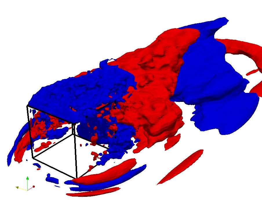
37 5.3. COMPARING DECOMPOSITION METHODS 25 U V W Figure 5.6. Isosurfaces of spatial POD modes 1,2,4 U V W Figure 5.7. Isosurfaces of spatial POD modes 1,3,5
Time-Dependent Simulations for the Directional Stability of High Speed Trains Under the Influence of Cross Winds or Cruising Inside Tunnels
 FLUID DYNAMICS APPLICATIONS IN GROUND TRANSPORTATION: Simulation, a primary delepment tool in the automotive industry, Lyon, France, 2005 Time-Dependent Simulations for the Directional Stability of High
Simulating Drag Crisis for a Sphere Using Skin Friction Boundary Conditions
 Simulating Drag Crisis for a Sphere Using Skin Friction Boundary Conditions Johan Hoffman May 14, 2006 Abstract In this paper we use a General Galerkin (G2) method to simulate drag crisis for a sphere,
IMPLEMENTATION OF POD AND DMD METHODS IN APACHE SPARK FRAMEWORK FOR SIMULATION OF UNSTEADY TURBULENT FLOW IN THE MODEL COMBUSTOR
 ECCOMAS Congress 2016 VII European Congress on Computational Methods in Applied Sciences and Engineering M. Papadrakakis, V. Papadopoulos, G. Stefanou, V. Plevris (eds.) Crete Island, Greece, 5 10 June
Turbulent Boundary Layers & Turbulence Models. Lecture 09
 Turbulent Boundary Layers & Turbulence Models Lecture 09 The turbulent boundary layer In turbulent flow, the boundary layer is defined as the thin region on the surface of a body in which viscous effects
RECONSTRUCTION OF TURBULENT FLUCTUATIONS FOR HYBRID RANS/LES SIMULATIONS USING A SYNTHETIC-EDDY METHOD
 RECONSTRUCTION OF TURBULENT FLUCTUATIONS FOR HYBRID RANS/LES SIMULATIONS USING A SYNTHETIC-EDDY METHOD N. Jarrin 1, A. Revell 1, R. Prosser 1 and D. Laurence 1,2 1 School of MACE, the University of Manchester,
Numerical Investigation of the Transonic Base Flow of A Generic Rocket Configuration
 1 Numerical Investigation of the Transonic Base Flow of A Generic Rocket Configuration A. Henze, C. Glatzer, M. Meinke, W. Schröder Institute of Aerodynamics, RWTH Aachen University, Germany March 21,
Calculations on a heated cylinder case
 Calculations on a heated cylinder case J. C. Uribe and D. Laurence 1 Introduction In order to evaluate the wall functions in version 1.3 of Code Saturne, a heated cylinder case has been chosen. The case
LARGE EDDY SIMULATION AND FLOW CONTROL OVER A 25 RAMP MODEL
 LARGE EDDY SIMULATION AND FLOW CONTROL OVER A 25 RAMP MODEL 09/11/2017 Paolo Casco Stephie Edwige Philippe Gilotte Iraj Mortazavi LES and flow control over a 25 ramp model : context 2 Context Validation
Manhar Dhanak Florida Atlantic University Graduate Student: Zaqie Reza
 REPRESENTING PRESENCE OF SUBSURFACE CURRENT TURBINES IN OCEAN MODELS Manhar Dhanak Florida Atlantic University Graduate Student: Zaqie Reza 1 Momentum Equations 2 Effect of inclusion of Coriolis force
Reduced-order models for flow control: balanced models and Koopman modes
 Reduced-order models for flow control: balanced models and Koopman modes Clarence W. Rowley, Igor Mezić, Shervin Bagheri, Philipp Schlatter, and Dan S. Henningson Abstract This paper addresses recent developments
arxiv: v1 [physics.flu-dyn] 11 Oct 2012
![arxiv: v1 [physics.flu-dyn] 11 Oct 2012](/thumbs/94/118739408.jpg "arxiv: v1 [physics.flu-dyn] 11 Oct 2012") Low-Order Modelling of Blade-Induced Turbulence for RANS Actuator Disk Computations of Wind and Tidal Turbines Takafumi Nishino and Richard H. J. Willden ariv:20.373v [physics.flu-dyn] Oct 202 Abstract
Low-Order Modelling of Blade-Induced Turbulence for RANS Actuator Disk Computations of Wind and Tidal Turbines Takafumi Nishino and Richard H. J. Willden ariv:20.373v [physics.flu-dyn] Oct 202 Abstract
Large-eddy simulations for wind turbine blade: rotational augmentation and dynamic stall
 Large-eddy simulations for wind turbine blade: rotational augmentation and dynamic stall Y. Kim, I.P. Castro, and Z.T. Xie Introduction Wind turbines operate in the atmospheric boundary layer and their
On the transient modelling of impinging jets heat transfer. A practical approach
 Turbulence, Heat and Mass Transfer 7 2012 Begell House, Inc. On the transient modelling of impinging jets heat transfer. A practical approach M. Bovo 1,2 and L. Davidson 1 1 Dept. of Applied Mechanics,
Side-View Mirror Vibrations Induced Aerodynamically by Separating Vortices
 Open Journal of Fluid Dynamics, 2016, 6, 42-56 Published Online March 2016 in SciRes. http://www.scirp.org/journal/ojfd http://dx.doi.org/10.4236/ojfd.2016.61004 Side-View Mirror Vibrations Induced Aerodynamically
Turbulence - Theory and Modelling GROUP-STUDIES:
 Lund Institute of Technology Department of Energy Sciences Division of Fluid Mechanics Robert Szasz, tel 046-0480 Johan Revstedt, tel 046-43 0 Turbulence - Theory and Modelling GROUP-STUDIES: Turbulence
Zonal hybrid RANS-LES modeling using a Low-Reynolds-Number k ω approach
 Zonal hybrid RANS-LES modeling using a Low-Reynolds-Number k ω approach S. Arvidson 1,2, L. Davidson 1, S.-H. Peng 1,3 1 Chalmers University of Technology 2 SAAB AB, Aeronautics 3 FOI, Swedish Defence
University of Birmingham
 MRes in Railway Systems Engineering and Integration College of Engineering, School of Civil Engineering University of Birmingham Aerodynamic of the Trains in Tunnels Samane Faramehr Student ID: 1137392
(U c. t)/b (U t)/b
/b (U t)/b") DYNAMICAL MODELING OF THE LARGE-SCALE MOTION OF A PLANAR TURBULENT JET USING POD MODES. S. Gordeyev 1 and F. O. Thomas 1 University of Notre Dame, Notre Dame, USA University of Notre Dame, Notre Dame,
DYNAMICAL MODELING OF THE LARGE-SCALE MOTION OF A PLANAR TURBULENT JET USING POD MODES. S. Gordeyev 1 and F. O. Thomas 1 University of Notre Dame, Notre Dame, USA University of Notre Dame, Notre Dame,
Active Control of Separated Cascade Flow
 Chapter 5 Active Control of Separated Cascade Flow In this chapter, the possibility of active control using a synthetic jet applied to an unconventional axial stator-rotor arrangement is investigated.
University of Huddersfield Repository
 University of Huddersfield Repository Malviya, Vihar, Gundala, Naresh and Mishra, Rakesh Effect of cross wind on aerodynamic coefficients of ground vehicles. Original Citation Malviya, Vihar, Gundala,
Numerical Methods in Aerodynamics. Turbulence Modeling. Lecture 5: Turbulence modeling
 Turbulence Modeling Niels N. Sørensen Professor MSO, Ph.D. Department of Civil Engineering, Alborg University & Wind Energy Department, Risø National Laboratory Technical University of Denmark 1 Outline
The effect of geometric parameters on the head loss factor in headers
 Fluid Structure Interaction V 355 The effect of geometric parameters on the head loss factor in headers A. Mansourpour & S. Shayamehr Mechanical Engineering Department, Azad University of Karaj, Iran Abstract
COURSE ON VEHICLE AERODYNAMICS Prof. Tamás Lajos University of Rome La Sapienza 1999
 COURSE ON VEHICLE AERODYNAMICS Prof. Tamás Lajos University of Rome La Sapienza 1999 1. Introduction Subject of the course: basics of vehicle aerodynamics ground vehicle aerodynamics examples in car, bus,
Turbulence Modeling I!
 Outline! Turbulence Modeling I! Grétar Tryggvason! Spring 2010! Why turbulence modeling! Reynolds Averaged Numerical Simulations! Zero and One equation models! Two equations models! Model predictions!
Before we consider two canonical turbulent flows we need a general description of turbulence.
 Chapter 2 Canonical Turbulent Flows Before we consider two canonical turbulent flows we need a general description of turbulence. 2.1 A Brief Introduction to Turbulence One way of looking at turbulent
A Computational Investigation of a Turbulent Flow Over a Backward Facing Step with OpenFOAM
 206 9th International Conference on Developments in esystems Engineering A Computational Investigation of a Turbulent Flow Over a Backward Facing Step with OpenFOAM Hayder Al-Jelawy, Stefan Kaczmarczyk
A Detached-Eddy-Simulation study
 A Detached-Eddy-Simulation study Proper-Orthogonal-Decomposition of the wake flow behind a model wind turbine J. Göing 1, J. Bartl 2, F. Mühle 3, L. Sætran 2, P.U. Thamsen 1 Technical University of Berlin
Hybrid LES RANS Method Based on an Explicit Algebraic Reynolds Stress Model
 Hybrid RANS Method Based on an Explicit Algebraic Reynolds Stress Model Benoit Jaffrézic, Michael Breuer and Antonio Delgado Institute of Fluid Mechanics, LSTM University of Nürnberg bjaffrez/breuer@lstm.uni-erlangen.de
Computation of Unsteady Flows With Moving Grids
 Computation of Unsteady Flows With Moving Grids Milovan Perić CoMeT Continuum Mechanics Technologies GmbH milovan@continuummechanicstechnologies.de Unsteady Flows With Moving Boundaries, I Unsteady flows
The Simulation of Wraparound Fins Aerodynamic Characteristics
 The Simulation of Wraparound Fins Aerodynamic Characteristics Institute of Launch Dynamics Nanjing University of Science and Technology Nanjing Xiaolingwei 00 P. R. China laithabbass@yahoo.com Abstract:
TURBULENT FLOW ACROSS A ROTATING CYLINDER WITH SURFACE ROUGHNESS
 HEFAT2014 10 th International Conference on Heat Transfer, Fluid Mechanics and Thermodynamics 14 16 July 2014 Orlando, Florida TURBULENT FLOW ACROSS A ROTATING CYLINDER WITH SURFACE ROUGHNESS Everts, M.,
The Computations of Jet Interaction on a Generic Supersonic Missile
 The Computations of Jet Interaction on a Generic Supersonic Missile *Jinbum Huh 1) and Seungsoo Lee 2) 1), 2) Department of Aerospace Engineering, Inha Univ., Incheon, Korea 2) slee@inha.ac.kr ABSTRACT
COMPUTATIONAL SIMULATION OF THE FLOW PAST AN AIRFOIL FOR AN UNMANNED AERIAL VEHICLE
 COMPUTATIONAL SIMULATION OF THE FLOW PAST AN AIRFOIL FOR AN UNMANNED AERIAL VEHICLE L. Velázquez-Araque 1 and J. Nožička 2 1 Division of Thermal fluids, Department of Mechanical Engineering, National University
Numerical Computations of Internal Combustion Engine related Transonic and Unsteady Flows
 Numerical Computations of Internal Combustion Engine related Transonic and Unsteady Flows by Olle Bodin February 2009 Technical Reports from Royal Institute of Technology KTH Mechanics SE-100 44 Stockholm,
There are no simple turbulent flows
 Turbulence 1 There are no simple turbulent flows Turbulent boundary layer: Instantaneous velocity field (snapshot) Ref: Prof. M. Gad-el-Hak, University of Notre Dame Prediction of turbulent flows standard
Unsteady CFD for Automotive Aerodynamics
 Unsteady CFD for Automotive Aerodynamics T. Indinger, B. Schnepf, P. Nathen, M. Peichl, TU München, Institute of Aerodynamics and Fluid Mechanics Prof. Dr.-Ing. N.A. Adams Outline 2 Motivation Applications
Large-Eddy Simulation for Turbulent Nature of Flow and Pressure Fields over Urban Building Arrays C. Hirose*, A. Hagishima, N. Ikegaya, and J. Tanimot
 Large-Eddy Simulation for Turbulent Nature of Flow and Pressure Fields over Urban Building Arrays C. Hirose*, A. Hagishima, N. Ikegaya, and J. Tanimoto Interdisciplinary Graduate School of Engineering
UNIVERSITY OF CALGARY. Base Region Topology of Turbulent Wake around Finite Wall-Mounted Cylinder with. Application of Low Order Flow Representation
 UNIVERSITY OF CALGARY Base Region Topology of Turbulent Wake around Finite Wall-Mounted Cylinder with Application of Low Order Flow Representation by Golriz Boorboor A THESIS SUBMITTED TO THE FACULTY OF
Turbulence modelling. Sørensen, Niels N. Publication date: Link back to DTU Orbit
 Downloaded from orbit.dtu.dk on: Dec 19, 2017 Turbulence modelling Sørensen, Niels N. Publication date: 2010 Link back to DTU Orbit Citation (APA): Sørensen, N. N. (2010). Turbulence modelling. Paper presented
Periodic planes v i+1 Top wall u i. Inlet. U m y. Jet hole. Figure 2. Schematic of computational domain.
 Flow Characterization of Inclined Jet in Cross Flow for Thin Film Cooling via Large Eddy Simulation Naqavi, I.Z. 1, Savory, E. 2 and Martinuzzi, R. J. 3 1,2 The Univ. of Western Ontario, Dept. of Mech.
Detached Eddy Simulation on Hypersonic Base Flow Structure of Reentry-F Vehicle
 Available online at www.sciencedirect.com ScienceDirect Procedia Engineering 00 (2014) 000 000 www.elsevier.com/locate/procedia APISAT2014, 2014 Asia-Pacific International Symposium on Aerospace Technology,
Stability of Plane Couette Flow and Pipe Poiseuille Flow PER-OLOV ÅSÉN
 Stability of Plane Couette Flow and Pipe Poiseuille Flow PER-OLOV ÅSÉN Doctoral Thesis Stockholm, Sweden, 2007 TRITA-CSC-A 2007:7 ISSN 1653-5723 ISRN KTH/CSC/A--07/07--SE ISBN 978-91-7178-651-7 CSC Skolan
Turbulence Modeling. Cuong Nguyen November 05, The incompressible Navier-Stokes equations in conservation form are u i x i
 Turbulence Modeling Cuong Nguyen November 05, 2005 1 Incompressible Case 1.1 Reynolds-averaged Navier-Stokes equations The incompressible Navier-Stokes equations in conservation form are u i x i = 0 (1)
NONLINEAR FEATURES IN EXPLICIT ALGEBRAIC MODELS FOR TURBULENT FLOWS WITH ACTIVE SCALARS
 June - July, 5 Melbourne, Australia 9 7B- NONLINEAR FEATURES IN EXPLICIT ALGEBRAIC MODELS FOR TURBULENT FLOWS WITH ACTIVE SCALARS Werner M.J. Lazeroms () Linné FLOW Centre, Department of Mechanics SE-44
Vortex shedding from slender surface mounted pyramids
 Vortex shedding from slender surface mounted pyramids M. J. Morrison 1, R. J. Martinuzzi 3, E. Savory 1, G. A. Kopp 2 1 Department of Mechanical and Materials Engineering, University of Western Ontario,
Publication 97/2. An Introduction to Turbulence Models. Lars Davidson, lada
 ublication 97/ An ntroduction to Turbulence Models Lars Davidson http://www.tfd.chalmers.se/ lada Department of Thermo and Fluid Dynamics CHALMERS UNVERSTY OF TECHNOLOGY Göteborg Sweden November 3 Nomenclature
DETACHED-EDDY SIMULATION OF FLOW PAST A BACKWARD-FACING STEP WITH A HARMONIC ACTUATION
 DETACHED-EDDY SIMULATION OF FLOW PAST A BACKWARD-FACING STEP WITH A HARMONIC ACTUATION Liang Wang*, Ruyun Hu*, Liying Li*, Song Fu* *School of Aerospace Engineering, Tsinghua University, Beijing 100084,
INVESTIGATION OF THE FLOW OVER AN OSCILLATING CYLINDER WITH THE VERY LARGE EDDY SIMULATION MODEL
 ECCOMAS Congress 2016 VII European Congress on Computational Methods in Applied Sciences and Engineering M. Papadrakakis, V. Papadopoulos, G. Stefanou, V. Plevris (eds.) Crete Island, Greece, 5 10 June
Aerodynamic force analysis in high Reynolds number flows by Lamb vector integration
 Aerodynamic force analysis in high Reynolds number flows by Lamb vector integration Claudio Marongiu, Renato Tognaccini 2 CIRA, Italian Center for Aerospace Research, Capua (CE), Italy E-mail: c.marongiu@cira.it
Uncertainty quantification for RANS simulation of flow over a wavy wall
 Uncertainty quantification for RANS simulation of flow over a wavy wall Catherine Gorlé 1,2,3, Riccardo Rossi 1,4, and Gianluca Iaccarino 1 1 Center for Turbulence Research, Stanford University, Stanford,
DIRECT NUMERICAL SIMULATIONS OF HIGH SPEED FLOW OVER CAVITY. Abstract
 3 rd AFOSR International Conference on DNS/LES (TAICDL), August 5-9 th, 2001, Arlington, Texas. DIRECT NUMERICAL SIMULATIONS OF HIGH SPEED FLOW OVER CAVITY A. HAMED, D. BASU, A. MOHAMED AND K. DAS Department
Masters in Mechanical Engineering. Problems of incompressible viscous flow. 2µ dx y(y h)+ U h y 0 < y < h,
+ U h y 0 < y < h,") Masters in Mechanical Engineering Problems of incompressible viscous flow 1. Consider the laminar Couette flow between two infinite flat plates (lower plate (y = 0) with no velocity and top plate (y =
Masters in Mechanical Engineering Problems of incompressible viscous flow 1. Consider the laminar Couette flow between two infinite flat plates (lower plate (y = 0) with no velocity and top plate (y =
Overview of Turbulent Reacting Flows
 Overview of Turbulent Reacting Flows Outline Various Applications Overview of available reacting flow models LES Latest additions Example Cases Summary Reacting Flows Applications in STAR-CCM+ Ever-Expanding
Simulation and improvement of the ventilation of a welding workshop using a Finite volume scheme code
 1 st. Annual (National) Conference on Industrial Ventilation-IVC2010 Feb 24-25, 2010, Sharif University of Technology, Tehran, Iran IVC2010 Simulation and improvement of the ventilation of a welding workshop
CFD DESIGN OF A GENERIC CONTROLLER FOR VORTEX-INDUCED RESONANCE
 Seventh International Conference on CFD in the Minerals and Process Industries CSIRO, Melbourne, Australia 9-11 December 2009 CFD DESIGN OF A GENERIC CONTROLLER FOR VORTEX-INDUCED RESONANCE Andrew A. ANTIOHOS,
Flow simulation and aerodynamic noise prediction for a high-speed train wheelset
 aeroacoustics volume 13 number 7 & 8 214 pages 533 552 533 Flow simulation and aerodynamic noise prediction for a high-speed train wheelset J. Y. Zhu 1, Z. W. Hu 1 and D. J. Thompson 2 1 Aerodynamics and
CFD Time Evolution of Heat Transfer Around A Bundle of Tubes In Staggered Configuration. G.S.T.A. Bangga 1*, W.A. Widodo 2
 CFD Time Evolution of Heat Transfer Around A Bundle of Tubes In Staggered Configuration G.S.T.A. Bangga 1*, W.A. Widodo 2 1,2 Department of mechanical engineering Field of study energy conversion Institut
CFD Study of Flow Over Parallel Ridges with Varying Height and Spacing
 Proceedings of the World Congress on Engineering 21 Vol II WCE 21, June 3 - July 2, 21, London, U.K. CFD Study of Flow Over Parallel Ridges with Varying Height and Spacing Lee Chin Yik, Salim Mohamed Salim,
Comparison of Turbulence Models in the Flow over a Backward-Facing Step Priscila Pires Araujo 1, André Luiz Tenório Rezende 2
 Comparison of Turbulence Models in the Flow over a Backward-Facing Step Priscila Pires Araujo 1, André Luiz Tenório Rezende 2 Department of Mechanical and Materials Engineering, Military Engineering Institute,
Part 3. Stability and Transition
 Part 3 Stability and Transition 281 Overview T. Cebeci 1 Recent interest in the reduction of drag of underwater vehicles and aircraft components has rekindled research in the area of stability and transition.
Numerical Investigation of Vortex Induced Vibration of Two Cylinders in Side by Side Arrangement
 Numerical Investigation of Vortex Induced Vibration of Two Cylinders in Side by Side Arrangement Sourav Kumar Kar a, 1,, Harshit Mishra a, 2, Rishitosh Ranjan b, 3 Undergraduate Student a, Assitant Proffessor
Drag reduction in a class 8 truck - scaled down model
 Drag reduction in a class 8 truck - scaled down model Vishwa Krishna. R 1, Suwathy. R 2, Pragadeesh. M 1, and Venkatesan. M 1,* 1 School of Mechanical Engineering, SASTRA Deemed University, Tirumalaisamudram,
Numerical Simulation of Rocket Engine Internal Flows
 Numerical Simulation of Rocket Engine Internal Flows Project Representative Masao Furukawa Authors Taro Shimizu Nobuhiro Yamanishi Chisachi Kato Nobuhide Kasagi Institute of Space Technology and Aeronautics,
APPLICATION OF HYBRID CFD/CAA TECHNIQUE FOR MODELING PRESSURE FLUCTUATIONS IN TRANSONIC FLOWS
 TASK QUARTERLY Vol. 17, Nos 3 4, 2013, pp. 145 154 APPLICATION OF HYBRID CFD/CAA TECHNIQUE FOR MODELING PRESSURE FLUCTUATIONS IN TRANSONIC FLOWS SŁAWOMIR DYKAS, WŁODZIMIERZ WRÓBLEWSKI AND SEBASTIAN RULIK
Simulation of Aeroelastic System with Aerodynamic Nonlinearity
 Simulation of Aeroelastic System with Aerodynamic Nonlinearity Muhamad Khairil Hafizi Mohd Zorkipli School of Aerospace Engineering, Universiti Sains Malaysia, Penang, MALAYSIA Norizham Abdul Razak School
ASSESSMENT OF RANS AND DES METHODS FOR THE AHMED BODY
 ECCOMAS Congress 2016 VII European Congress on Computational Methods in Applied Sciences and Engineering M. Papadrakakis, V. Papadopoulos, G. Stefanou, V. Plevris (eds.) Crete Island, Greece, 5 10 June
Contents. I Introduction 1. Preface. xiii
 Contents Preface xiii I Introduction 1 1 Continuous matter 3 1.1 Molecules................................ 4 1.2 The continuum approximation.................... 6 1.3 Newtonian mechanics.........................
Aerodynamic Loads in Open Air of High Speed Trains: Analysis of Experimental Data
 Paper 54 Abstract The homologation of high-speed trains is a demanding and expensive procedure. In particular, the evaluation of train slipstream according to the standard TSI, 2008 is divided in two different
Towards Reduced Order Modeling (ROM) for Gust Simulations
 for Gust Simulations") Towards Reduced Order Modeling (ROM) for Gust Simulations S. Görtz, M. Ripepi DLR, Institute of Aerodynamics and Flow Technology, Braunschweig, Germany Deutscher Luft und Raumfahrtkongress 2017 5. 7. September
Towards Reduced Order Modeling (ROM) for Gust Simulations S. Görtz, M. Ripepi DLR, Institute of Aerodynamics and Flow Technology, Braunschweig, Germany Deutscher Luft und Raumfahrtkongress 2017 5. 7. September
White Paper FINAL REPORT AN EVALUATION OF THE HYDRODYNAMICS MECHANISMS WHICH DRIVE THE PERFORMANCE OF THE WESTFALL STATIC MIXER.
 White Paper FINAL REPORT AN EVALUATION OF THE HYDRODYNAMICS MECHANISMS WHICH DRIVE THE PERFORMANCE OF THE WESTFALL STATIC MIXER Prepared by: Dr. Thomas J. Gieseke NUWCDIVNPT - Code 8233 March 29, 1999
arxiv: v1 [physics.flu-dyn] 4 Aug 2014
![arxiv: v1 [physics.flu-dyn] 4 Aug 2014](/thumbs/83/87633147.jpg "arxiv: v1 [physics.flu-dyn] 4 Aug 2014") A hybrid RANS/LES framework to investigate spatially developing turbulent boundary layers arxiv:1408.1060v1 [physics.flu-dyn] 4 Aug 2014 Sunil K. Arolla a,1, a Sibley School of Mechanical and Aerospace
A hybrid RANS/LES framework to investigate spatially developing turbulent boundary layers arxiv:1408.1060v1 [physics.flu-dyn] 4 Aug 2014 Sunil K. Arolla a,1, a Sibley School of Mechanical and Aerospace
Introduction to CFD modelling of source terms and local-scale atmospheric dispersion (Part 1 of 2)
") 1 Introduction to CFD modelling of source terms and local-scale atmospheric dispersion (Part 1 of 2) Atmospheric Dispersion Modelling Liaison Committee (ADMLC) meeting 15 February 2018 Simon Gant, Fluid
1 Introduction to CFD modelling of source terms and local-scale atmospheric dispersion (Part 1 of 2) Atmospheric Dispersion Modelling Liaison Committee (ADMLC) meeting 15 February 2018 Simon Gant, Fluid
Fluid Dynamics Exercises and questions for the course
 Fluid Dynamics Exercises and questions for the course January 15, 2014 A two dimensional flow field characterised by the following velocity components in polar coordinates is called a free vortex: u r
Large Eddy Simulation as a Powerful Engineering Tool for Predicting Complex Turbulent Flows and Related Phenomena
 29 Review Large Eddy Simulation as a Powerful Engineering Tool for Predicting Complex Turbulent Flows and Related Phenomena Masahide Inagaki Abstract Computational Fluid Dynamics (CFD) has been applied
A numerical investigation of tip clearance flow in Kaplan water turbines
 Published in the proceedings of HYDROPOWER INTO THE NEXT CENTURY - III, 1999. ISBN 9522642 9 A numerical investigation of tip clearance flow in Kaplan water turbines M.Sc. H. Nilsson Chalmers University
Computational and Experimental Studies of Fluid flow and Heat Transfer in a Calandria Based Reactor
 Computational and Experimental Studies of Fluid flow and Heat Transfer in a Calandria Based Reactor SD Ravi 1, NKS Rajan 2 and PS Kulkarni 3 1 Dept. of Aerospace Engg., IISc, Bangalore, India. ravi@cgpl.iisc.ernet.in
1. Introduction, tensors, kinematics
 1. Introduction, tensors, kinematics Content: Introduction to fluids, Cartesian tensors, vector algebra using tensor notation, operators in tensor form, Eulerian and Lagrangian description of scalar and
CHARACTERISTICS OF ELLIPTIC CO-AXIAL JETS
 ELECTRIC POWER 2003 March 4-6, 2003 George R Brown Convention Center, Houston, TX EP 03 Session 07C: Fuels, Combustion and Advanced Cycles - Part II ASME - FACT Division CHARACTERISTICS OF ELLIPTIC CO-AXIAL
DESIGN OF A HIGH SPEED TRAIN USING A MULTIPHYSICAL APPROACH
 DESIGN OF A HIGH SPEED TRAIN USING A MULTIPHYSICAL APPROACH Aitor Berasarte Technologies Management Area Technology Division CAF WHAT DO WE ANALYSE? AERODYNAMICS STRUCTURAL ANALYSIS DYNAMICS NOISE & VIBRATIONS
Numerical Simulation of Unsteady Flow with Vortex Shedding Around Circular Cylinder
 Numerical Simulation of Unsteady Flow with Vortex Shedding Around Circular Cylinder Ali Kianifar, Edris Yousefi Rad Abstract In many applications the flow that past bluff bodies have frequency nature (oscillated)
LDA-Measurements of Jets in Crossflow for Effusion Cooling Applications
 LDA-Measurements of Jets in Crossflow for Effusion Cooling Applications by K. M. Bernhard Gustafsson Department of Thermo and Fluid Dynamics Chalmers University of Technology SE-41296 Göteborg, SWEDEN
Available online at ScienceDirect. Procedia Engineering 79 (2014 ) 49 54
 49 54") Available online at www.sciencedirect.com ScienceDirect Procedia Engineering 79 (2014 ) 49 54 37th National Conference on Theoretical and Applied Mechanics (37th NCTAM 2013) & The 1st International Conference
Available online at www.sciencedirect.com ScienceDirect Procedia Engineering 79 (2014 ) 49 54 37th National Conference on Theoretical and Applied Mechanics (37th NCTAM 2013) & The 1st International Conference
Aero Acoustics Analysis of Car s ORVM
 International Journal of Science and Engineering Investigations vol. 4, issue 38, March 2015 ISSN: 2251-8843 Aero s Analysis of Car s ORVM Roshan Kumar Gopal 1, Remin V. 2, Richard Sen 3 1 Technical Support
Prospects for High-Speed Flow Simulations
 Prospects for High-Speed Flow Simulations Graham V. Candler Aerospace Engineering & Mechanics University of Minnesota Support from AFOSR and ASDR&E Future Directions in CFD Research: A Modeling & Simulation
Propeller Loads of Large Commercial Vessels at Crash Stop
 Second International Symposium on Marine Propulsors smp 11, Hamburg, Germany, June 2011 Propeller Loads of Large Commercial Vessels at Crash Stop J.W. Hur, H. Lee, B.J. Chang 1 1 Hyundai Heavy Industries,
DNS STUDY OF TURBULENT HEAT TRANSFER IN A SPANWISE ROTATING SQUARE DUCT
 10 th International Symposium on Turbulence and Shear Flow Phenomena (TSFP10), Chicago, USA, July, 2017 DNS STUDY OF TURBULENT HEAT TRANSFER IN A SPANWISE ROTATING SQUARE DUCT Bing-Chen Wang Department
A combined application of the integral wall model and the rough wall rescaling-recycling method
 AIAA 25-299 A combined application of the integral wall model and the rough wall rescaling-recycling method X.I.A. Yang J. Sadique R. Mittal C. Meneveau Johns Hopkins University, Baltimore, MD, 228, USA
Colloquium FLUID DYNAMICS 2012 Institute of Thermomechanics AS CR, v.v.i., Prague, October 24-26, 2012 p.
 Colloquium FLUID DYNAMICS 212 Institute of Thermomechanics AS CR, v.v.i., Prague, October 24-26, 212 p. ON A COMPARISON OF NUMERICAL SIMULATIONS OF ATMOSPHERIC FLOW OVER COMPLEX TERRAIN T. Bodnár, L. Beneš
A Solution Method for the Reynolds-Averaged Navier-Stokes Equation
 A Solution Method for the Reynolds-Averaged Navier-Stokes Equation T.-W. Lee Mechanical and Aerospace Engineering, Arizona State University, Tempe, AZ, 8587 Abstract- Navier-Stokes equations are difficult
LARGE EDDY SIMULATION OF MASS TRANSFER ACROSS AN AIR-WATER INTERFACE AT HIGH SCHMIDT NUMBERS
 The 6th ASME-JSME Thermal Engineering Joint Conference March 6-, 3 TED-AJ3-3 LARGE EDDY SIMULATION OF MASS TRANSFER ACROSS AN AIR-WATER INTERFACE AT HIGH SCHMIDT NUMBERS Akihiko Mitsuishi, Yosuke Hasegawa,
Resolving the dependence on free-stream values for the k-omega turbulence model
 Resolving the dependence on free-stream values for the k-omega turbulence model J.C. Kok Resolving the dependence on free-stream values for the k-omega turbulence model J.C. Kok This report is based on
DNS, LES, and wall-modeled LES of separating flow over periodic hills
 Center for Turbulence Research Proceedings of the Summer Program 4 47 DNS, LES, and wall-modeled LES of separating flow over periodic hills By P. Balakumar, G. I. Park AND B. Pierce Separating flow in
Numerical and Experimental Investigation of the Flow-Induced Noise of a Wall Mounted Airfoil
 Numerical and Experimental Investigation of the Flow-Induced Noise of a Wall Mounted Airfoil Paul Croaker, Danielle Moreau, Manuj Awasthi, Mahmoud Karimi, Con Doolan, Nicole Kessissoglou School of Mechanical
A NOVEL VLES MODEL FOR TURBULENT FLOW SIMULATIONS
 June 30 - July 3, 2015 Melbourne, Australia 9 7B-4 A NOVEL VLES MODEL FOR TURBULENT FLOW SIMULATIONS C.-Y. Chang, S. Jakirlić, B. Krumbein and C. Tropea Institute of Fluid Mechanics and Aerodynamics /
2 Navier-Stokes Equations
 1 Integral analysis 1. Water enters a pipe bend horizontally with a uniform velocity, u 1 = 5 m/s. The pipe is bended at 90 so that the water leaves it vertically downwards. The input diameter d 1 = 0.1
EVALUATION OF FOUR TURBULENCE MODELS IN THE INTERACTION OF MULTI BURNERS SWIRLING FLOWS
 EVALUATION OF FOUR TURBULENCE MODELS IN THE INTERACTION OF MULTI BURNERS SWIRLING FLOWS A Aroussi, S Kucukgokoglan, S.J.Pickering, M.Menacer School of Mechanical, Materials, Manufacturing Engineering and
RANS-LES inlet boundary condition for aerodynamic and aero-acoustic. acoustic applications. Fabrice Mathey Davor Cokljat Fluent Inc.
 RANS-LES inlet boundary condition for aerodynamic and aero-acoustic acoustic applications Fabrice Mathey Davor Cokljat Fluent Inc. Presented by Fredrik Carlsson Fluent Sweden ZONAL MULTI-DOMAIN RANS/LES
An evaluation of a conservative fourth order DNS code in turbulent channel flow
 Center for Turbulence Research Annual Research Briefs 2 2 An evaluation of a conservative fourth order DNS code in turbulent channel flow By Jessica Gullbrand. Motivation and objectives Direct numerical
Chapter 3 Lecture 8. Drag polar 3. Topics. Chapter-3
 Chapter 3 ecture 8 Drag polar 3 Topics 3.2.7 Boundary layer separation, adverse pressure gradient and favourable pressure gradient 3.2.8 Boundary layer transition 3.2.9 Turbulent boundary layer over a