ME2251 HEAT AND MASS TRANSFER L T P C
|
|
|
- Clare Webster
- 5 years ago
- Views:
Transcription
1 ME2251 HEAT AND MASS TRANSFER L T P C UNIT I CONDUCTION 11+3 Basic Concepts Mechanism of Heat Transfer Conduction, Convection and Radiation Fourier Law of Conduction - General Differential equation of Heat Conduction Cartesian and Cylindrical Coordinates One Dimensional Steady State Heat Conduction Conduction through Plane Wall, Cylinders and Spherical systems Composite Systems Conduction with Internal Heat Generation Extended Surfaces Unsteady Heat Conduction Lumped Analysis Use of Heislers Chart. UNIT II CONVECTION 10+3 Basic Concepts Heat Transfer Coefficients Boundary Layer Concept Types of Convection Forced Convection Dimensional Analysis External Flow Flow over Plates, Cylinders and Spheres Internal Flow Laminar and Turbulent Flow Combined Laminar and Turbulent Flow over Bank of tubes Free Convection Dimensional Analysis Flow over Vertical Plate, Horizontal Plate, Inclined Plate, Cylinders and Spheres. UNIT III PHASE CHANGE HEAT TRANSFER AND HEAT EXCHANGERS 9+3 Nusselts theory of condensation-pool boiling, flow boiling, correlations in boiling and condensation. Types of Heat Exchangers Heat Exchanger Analysis LMTD Method and NTU - Effectiveness Overall Heat Transfer Coefficient Fouling Factors. UNIT IV RADIATION 8+3 Basic Concepts, Laws of Radiation Stefan Boltzman Law, Kirchoffs Law Black Body Radiation Grey body radiation -Shape Factor Algebra Electrical Analogy Radiation Shields Introduction to Gas Radiation UNIT V MASS TRANSFER 7+3 Basic Concepts Diffusion Mass Transfer Fick s Law of Diffusion Steady state Molecular Diffusion Convective Mass Transfer Momentum, Heat and Mass Transfer Analogy Convective Mass Transfer Correlations L = 45 T = 15 TOTAL = 60 PERIODS TEXT BOOKS 1. Sachdeva R C, Fundamentals of Engineering Heat and Mass Transfer New Age International, Frank P. Incropera and David P. DeWitt, Fundamentals of Heat and Mass Transfer, John Wiley and Sons, REFERENCE BOOKS 1. Yadav R Heat and Mass Transfer Central Publishing House,
2 2. Ozisik M.N, Heat Transfer, McGraw-Hill Book Co., Nag P.K, Heat Transfer, Tata McGraw-Hill, New Delhi, Holman J.P Heat and Mass Transfer Tata McGraw-Hill, Kothandaraman C.P Fundamentals of Heat and Mass Transfer New Age International, New Delhi, UNIT I - CONDUCTION INTRODUCTORY CONCEPTS AND BASIC LAWS OF HEAT TRANSFER We recall from our knowledge of thermodynamics that heat is a form of energy transfer that takes place from a region of higher temperature to a region of lower temperature solely due to the temperature difference between the two regions. With the knowledge of thermodynamics we can determine the amount of heat transfer for any system undergoing any process from one equilibrium state to another. Thus the thermodynamics knowledge will tell us only how much heat must be transferred to achieve a specified change of state of the system. But in practice we are more interested in knowing the rate of heat transfer (i.e. heat transfer per unit time) rather than the amount. This knowledge of rate of heat transfer is necessary for a design engineer to design all types of heat transfer equipments like boilers, condensers, furnaces, cooling towers, dryers etc. The subject of heat transfer deals with the determination of the rate of heat transfer to or from a heat exchange equipment and also the temperature at any location in the device at any instant of time. The basic requirement for heat transfer is the presence of a temperature difference. The temperature difference is the driving force for heat transfer, just as the voltage difference for electric current flow and pressure difference for fluid flow. One of the parameters, on which the rate of heat transfer in a certain direction depends, is the magnitude of the temperature gradient in that direction. The larger the gradient higher will be the rate of heat transfer. Heat Transfer Mechanisms:- There are three mechanisms by which heat transfer can take place. All the three modes require the existence of temperature difference. The three mechanisms are: (i) conduction, 2
3 (ii) convection and (iii) radiation Conduction:- It is the energy transfer that takes place at molecular levels. Conduction is the transfer of energy from the more energetic molecules of a substance to the adjacent less energetic molecules as a result of interaction between the molecules. In the case of liquids and gases conduction is due to collisions and diffusion of the molecules during their random motion. In solids, it is due to the vibrations of the molecules in a lattice and motion of free electrons. Fourier s Law of Heat Conduction:- The empirical law of conduction based on experimental results is named after the French Physicist Joseph Fourier. The law states that the rate of heat flow by conduction in any medium in any direction is proportional to the area normal to the direction of heat flow and also proportional to the temperature gradient in that direction. For example the rate of heat transfer in x-direction can be written according to Fourier s law as Qx α A (dt / dx).(1.1) Or Qx = k A (dt / dx) W....(1.2) In equation (1.2), Qx is the rate of heat transfer in positive x-direction through area A of the medium normal to x-direction, (dt/dx) is the temperature gradient and k is the constant of proportionality and is a material property called thermal conductivity. Since heat transfer has to take place in the direction of decreasing temperature, (dt/dx) has to be negative in the direction of heat transfer. Therefore negative sign has to be introduced in equation (1.2) to make Qx positive in the direction of decreasing temperature, thereby satisfying the second law of thermodynamics. If equation (1.2) is divided throughout by A we have 3
4 qx is called the heat flux. qx = (Qx / A) = k (dt / dx) W/m 2..(1.3) In the case of solids heat conduction is due to two effects: the vibration of lattice induced by the vibration of molecules positioned at relatively fixed positions, and energy transported due to the motion of free electrons. The relatively high thermal conductivities of pure metals are primarily due to the electronic component. The lattice component of thermal conductivity strongly depends on the way the molecules are arranged. For example, diamond, which is highly ordered crystalline solid, has the highest thermal conductivity at room temperature. 4

5 Unlike metals, which are good electrical and heat conductors, crystalline solids such as diamond and semiconductors such as silicon are good heat conductors but poor electrical conductors. Hence such materials find widespread use in electronic industry. Despite their high price, diamond heat sinks are used in the cooling of sensitive electronic components because of their excellent thermal conductivity. Silicon oils and gaskets are commonly used in the packaging of electronic components because they provide both good thermal contact and good electrical insulation. 5
6 One would expect that metal alloys will have high thermal conductivities, because pure metals have high thermal conductivities. For example one would expect that the value of the thermal conductivity k of a metal alloy made of two metals with thermal conductivities k1 and k2 would lie between k1 and k2.but this is not the case. In fact k of a metal alloy will be less than that of either metal. The thermal conductivities of materials vary with temperature. But for some materials the variation is insignificant even for wide temperature range. At temperatures near absolute zero, the thermal conductivities of certain solids are extremely large. For example copper at 20 K will have a thermal conductivity of 20,000 W / (m-k), which is about 50 times the conductivity at room temperature. The temperature dependence of thermal conductivity makes the conduction heat transfer analysis more complex and involved. As a first approximation analysis for solids with variable conductivity is carried out assuming constant thermal conductivity which is an average value of the conductivity for the temperature range of interest. Derive general heat conduction equation in Cartesian coordinates? Consider a small rectangular element of sides dx, dy and dz as shown in figure. The energy balance of this rectangular element is obtained from first law of thermodynamics. Net heat conducted into element from all the + coordinate directions Heat generated within the element = Heat stored in the element Net heat conducted into element from all the coordinate directions: As per the Fourier law of heat conduction the rate of heat flow into the element in X, Y, Z directions through face ABCD, ABEF, ADHE are 6
7 The rate of heat flow out of the element in X direction through the face EFGH is 7
8 8

9 Heat transfer by conduction through a simple plane wall A good way to start is by looking at the simplest possible case, a metal wall with uniform thermal properties and specified surface temperatures. T 1 and T 2 are the surface temperatures either side of the metal wall, of thickness L; and the temperature difference between the two surfaces is ΔT. Ignoring the possible resistance to heat flow at the two surfaces, the process of heat flow 9
10 through the wall can be derived from Fourier's law of conduction as shown in following equation. The term 'barrier' refers to a heat resistive film or the metal wall of a heat exchanger. Heat Conduction through Hollow Cylinder 10
11 11

12 Heat Conduction through Hollow Sphere Conductance through a Flat Composite Wall 12
13 13
14 Heat Transfer From a Fin Fins are used in a large number of applications to increase the heat transfer from surfaces. Typically, the fin material has a high thermal conductivity. The fin is exposed to a flowing fluid, which cools or heats it, with the high thermal conductivity allowing increased heat being conducted from the wall through the fin. The design of cooling fins is encountered in many situations and we thus examine heat transfer in a fin as a way of defining some criteria for design. 14
15 Solved Problems 1. Consider a 4-m-high, 6-m-wide, and 0.3-m-thick brick Wall whose thermal conductivity is k =0.8 W/m C. On a Certain day, the temperatures of the inner and the outer surfaces Of the wall are measured to be 14 C and 6 C, respectively. Determine the rate of heat loss through the wall on that day. 15
16 Assumptions 1 Heat transfer through the wall is steady since the surface temperatures remain constant at the specified values. 2 Heat transfer is one-dimensional since any significant temperature gradients will exist in the direction from the indoors to the outdoors. 3. Thermal conductivity is constant. Properties The thermal conductivity is given to be k = 0.8 W/m C Analysis The surface area of the wall and the rate of heat loss through the wall are 2. Consider a 4-m-high, 6-m-wide, and 0.3-m-thick brick wall whose thermal conductivity is k =0.8 W/m C. On a certain day, the temperatures of the inner and the outer surfaces of the wall are measured to be 14 C and 6 C, respectively. Determine the rate of heat loss through the wall on that day. assuming the space between the two glass layers is evacuated. Assumptions 1 Heat transfer through the window is steady since the indoor and outdoor temperatures remain constant at the specified values. 2 Heat transfer is one-dimensional since any significant temperature gradients will exist in the direction from the indoors to the outdoors. 3 Thermal conductivities of the glass and air are constant. 4 Heat transfer by radiation is negligible. 16

17 Properties The thermal conductivity of the glass and air are given to be kglass = 0.78 W/m. C and kair = W/m. C. Analysis The area of the window and the individual resistances are 3. A cylindrical resistor element on a circuit board dissipates 0.15 W of power in an environment at 40 C. The resistor is 1.2 cm long, and has a diameter of 0.3 cm. 17
 the surface temperature of the resistor for a combined convection and radiation heat transfer coefficient of 9 W/m2 C. Assumptions 1 Steady operating conditions exist.")
18 Assuming heat to be transferred uniformly from all surfaces, determine (a) the amount of heat this resistor dissipates during a 24-h period, (b) the heat flux on the surface of the resistor, in W/m2, and (c) the surface temperature of the resistor for a combined convection and radiation heat transfer coefficient of 9 W/m2 C. Assumptions 1 Steady operating conditions exist. 2 Heat is transferred uniformly from all surfaces of the resistor. Analysis (a) The amount of heat this resistor dissipates during a 24-hour period is 18
19 4. Heat is to be conducted along a circuit board that has a copper layer on one side. The circuit board is 15 cm long and 15 cm wide, and the thicknesses of the copper and epoxy layers are 0.1 mm and 1.2 mm, respectively. Disregarding heat transfer from side surfaces, determine the percentages of heat conduction along the copper (k =386 W/m C) and epoxy (k = 0.26 W/m C) layers. Also determine the effective thermal Conductivity of the board. Assumptions 1 Steady operating conditions exist. 2 Heat transfer is onedimensional since heat transfer from the side surfaces is disregarded 3 Thermal conductivities are constant. Properties The thermal conductivities are given to be k = 386 W/m C for copper and 0.26 W/m C for epoxy layers. Analysis We take the length in the direction of heat transfer to be L and the width of the board to be w. Then heat conduction along this two-layer board can be expressed as Heat conduction along an equivalent board of thickness t = tcopper + tepoxy and thermal conductivity keff can be expressed as 19
20 Setting the two relations above equal to each other and solving for the effective conductivity gives Note that heat conduction is proportional to kt. Substituting, the fractions of heat conducted along the copper and epoxy layers as well as the effective thermal conductivity of the board are determined to be 20
21 5. A1-mm-thick copper plate (k = 386 W/m C) is sandwiched between two 5-mm-thick epoxy boards (k = 0.26 W/m C) that are 15 cm 20 cm in size. If the thermal contact conductance on both sides of the copper plate is estimated to be 6000 W/m C, determine the error involved in the total thermal resistance of the plate if the thermal contact conductance are ignored. Assumptions 1 Steady operating conditions exist. 2 Heat transfer is one-dimensional since the plate is large. 3 Thermal conductivities are constant. Properties The thermal conductivities are given to be k = 386 W/m. C for copper plates and k = 0.26 W/m. C for epoxy boards. The contact conductance at the interface of copperepoxy layers is given to be hc = 6000 W/m2. C Analysis The thermal resistances of different layers for unit surface area of 1 m2 are 21
22 The total thermal resistance is Then the percent error involved in the total thermal resistance of the plate if the thermal contact resistances are ignored is determined to be which is negligible. 6. A 4-m-high and 6-m-wide wall consists of a long 18-cm 30-cm cross section of horizontal bricks (k =0.72 W/m C) separated by 3-cm-thick plaster layers (k = 0.22 W/m C). There are also 2-cm-thick plaster layers on each side of the wall, and a 2-cmthick rigid foam (k =0.026 W/m C) on the inner side of the wall. The indoor and the outdoor temperatures are 22 C and =4 C, and the convection heat transfer coefficients on the inner and the outer sides are h1 = 10 W/m2 C and h2 =20 W/m2 C, respectively. Assuming one-dimensional heat transfer and disregarding radiation, determine the rate of heat transfer through the wall. 22
23 Assumptions 1 Heat transfer is steady since there is no indication of change with time. 2 Heat transfer through the wall is one-dimensional. 3 Thermal conductivities are constant. 4 Heat transfer by radiation is disregarded. Properties The thermal conductivities are given to be k = 0.72 W/m C for bricks, k = 0.22 W/m C for plaster layers, and k = W/m C for the rigid foam. Analysis We consider 1 m deep and 0.33 m high portion of wall which is representative of the entire wall. The thermal resistance network and individual resistances are 23
24 The steady rate of heat transfer through the wall per is 0.33 m 2 Then steady rate of heat transfer through the entire wall becomes 24
 the rate of heat loss from the steam pipe, (c) the thickness of fiberglass insulation (k =0.")
25 7. A50-m-long section of a steam pipe whose outer diameter is 10 cm passes through an open space at 15 C. The average temperature of the outer surface of the pipe is measured to be 150 C. If the combined heat transfer coefficient on the outer surface of the pipe is 20 W/m2. C, determine (a) the rate of heat loss from the steam pipe, (c) the thickness of fiberglass insulation (k =0.035 W/m C) needed in order to save 90 percent of the heat lost. Assume the pipe Temperature to remain constant at 150 C. Assumptions 1 Heat transfer is steady since there is no indication of any change with time. 2 Heat transfer is one-dimensional since there is thermal symmetry about the center line and no variation in the axial direction. 3 Thermal conductivity is constant. 4 The thermal contact resistance at the interface is negligible. 5 The pipe temperature remains constant at about 150 C with or without insulation. 6 The combined heat transfer coefficient on the outer surface remains constant even after the pipe is insulated. Properties The thermal conductivity of fiberglass insulation is given to be k = W/m. C. Analysis (a) The rate of heat loss from the steam pipe is (c) In order to save 90% of the heat loss and thus to reduce it to ,412 = 4241 W, the thickness of insulation needed is determined from 25
26 8. Consider a 2-m-high electric hot water heater that has a diameter of 40 cm and maintains the hot water at 55 C. The tank is located in a small room whose average temperature i 27 C, and the heat transfer coefficients on the inner and outer surfaces of the heater are 50 and 12 W/m2 C, respectively. The tank is placed in another 46-cmdiameter sheet metal tank of negligible thickness, and the space between the two tanks is filled with foam insulation (k =0.03 W/m C). The thermal resistances of the water tank and the outer thin sheet metal shell are very small and can be neglected. The price of electricity is $0.08/kWh, and the home owner pays $280 a year for water heating. Determine the fraction of the hot water energy cost of this household that is due to the heat loss from the tank. Hot water tank insulation kits consisting of 3-cm-thick fiberglass insulation (k = W/m C) large enough to wrap the entire tank are available in the market for about $30. If such an insulation is installed on this water tank by the home owner himself, how long will it take for this additional insulation to pay for itself? Assumptions 1 Heat transfer is steady since there is no indication of any change with time. 2 Heat transfer is one-dimensional since there is thermal symmetry about the centerline and no variation in the axial direction. 3 Thermal properties are constant. 4 The thermal contact resistance at the interface is negligible. 5 Heat transfer coefficient accounts for the radiation effects, if any. 26
27 Properties The thermal conductivity of plastic cover is given to be k = 0.15 W/m. C. Analysis In steady operation, the rate of heat transfer from the wire is equal to the heat generated within the wire, Doubling the thickness of the plastic cover will increase the outer radius of the wire to 3 mm, which is less than the critical radius of insulation. Therefore, doubling the thickness of plastic cover will increase the rate of heat loss and decrease the interface temperature. 9.Obtain a relation for the fin efficiency for a fin of constant cross-sectional area Ac, perimeter p, length L, and thermal conductivity k exposed to convection to a medium at T with a heat transfer coefficient h. Assume the fins are sufficiently long so that the temperature of the fin at the tip is nearly T. Take the temperature of the fin at the base to be Tb and neglect heat transfer from the fin tips. Simplify the relation for (a) a circular fin of diameter D and (b) rectangular fins of thickness t.. 27


28 Assumptions 1 The fins are sufficiently long so that the temperature of the fin at the tip is nearly. 2 Heat transfer from the fin tips is negligible Analysis Taking the temperature of the fin at the base to be and using the heat transfer relation for a long fin, fin efficiency for long fins can be expressed as Tb This relation can be simplified for a circular fin of diameter D and rectangular fin of thickness t and width w to be 10.Ahot plate is to be cooled by attaching aluminum pin fins on one side. The rate of heat transfer from the 1 m by 1 m section of the plate and the effectiveness of the fins are to be determined. 28

29 Assumptions 1 Steady operating conditions exist. 2 The temperature along the fins varies in one direction only (normal to the plate). 3 Heat transfer from the fin tips is negligible. 4 The heat transfer coefficient is constant and uniform over the entire fin surface. 5 The thermal properties of the fins are constant. 6 The heat transfer coefficient accounts for the effect of radiation from the fins. Properties The thermal conductivity of the aluminium plate and fins is given to be k = 237 W/m. C. Analysis Noting that the cross-sectional areas of the fins are constant, the efficiency of the circular fins can be determined to be The number of fins, finned and unfinned surface areas, and heat transfer rates from those areas are 29
30 30
31 UNIT II CONVECTION INTRODUCTION The preceding unit have considered the mechanism and calculation of conduction heat transfer. Convection was considered only insofar as it related to the boundary conditions imposed on a conduction problem. We now wish to examine the methods of calculating convection heat transfer and, in particular, the ways of predicting the value of the convection heat-transfer coefficient h. The subject of convection heat transfer requires an energy balance long with an analysis of the fluid dynamics of the problems concerned. Our discussion in this chapter will first consider some of the simple relations of fluid dynamics and boundary layer analysis that are important for a basic understanding of convection heat transfer. Next, we shall impose an energy balance on the flow system and determine the influence of the flow on the temperature gradients in the fluid. Finally, having obtained a knowledge of the temperature distribution, the heat-transfer rate from a heated surface to a fluid that is forced over it may be determined. The process of heat transfer between a surface and a fluid flowing in contact with it is called convection.if the flow is caused by an external device like a pump or blower, it is termed as forced convection. If the flow is caused by the buoyant forcesgenerated by 31

32 heating or cooling of the fluid the process is called as natural or free convection. Fig. 1. Heat transfer through a fluid sandwiched between two parallel plates. MECHANISM OF CONVECTION In conduction, energy is transferred as heat either due to free electron flux or lattice vibration. There is no movement of mass in the direction of energy flow. In convection, 32

33 energy flow occurs at the surface purely by conduction. But in the next layers both conduction and diffusion-mass movement in the molecular level or macroscopic level occurs. Due to the mass movement the rate the rate of energy transfer is higher. Higher the rate of mass movement, higher will be the heat flow rate. Consider the cooling of a hot iron block with a fan blowing air over its top surface, as shown in Figure 2. We know that heat will be transferred from the hot block to the surrounding cooler air, and the block will eventually cool. We also know that the block will cool faster if the fan is switched to a higher speed. Replacing air by water will enhance the convection heat transfer even more. Fig. 2. The cooling of a hot block by forced convection. Experience shows that convection heat transfer strongly depends on the fluid properties dynamic viscosity, thermal conductivity k, density, and specific heat Cp, as well as the fluid velocity. It also depends on the geometryand the roughness of the solid surface, in addition to the type of fluid flow(such as being streamlined or turbulent). Thus, we expect the convection heat transfer relations to be rather complex because of the dependence of convection on so many variables. This is not surprising, since convection is the most complex mechanism of heat transfer. Despite the complexity of convection, the rate of convection heat transfer is observed to 33
34 be proportional to the temperature difference and is conveniently expressed by Newton s law of cooling as Judging from its units, the convection heat transfer coefficient h can be defined as the rate of heat transfer between a solid surface and a fluid per unit surface area per unit temperature difference. CLASSIFICATION OF FLUID FLOWS Convection heat transfer is closely tied with fluid mechanics, which is the science that deals with the behavior of fluids at rest or in motion, and the interaction of fluids with solids or other fluids at the boundaries. There are a wide variety of fluid flow problems encountered in practice, and it is usually convenient to classify them on the basis of some common characteristics to make it feasible to study them in groups. There are many ways to classify the fluid flow problems, and below we present some general categories. Viscous versus Inviscid Flow When two fluid layers move relative to each other, a friction force develops between 34
35 them and the slower layer tries to slow down the faster layer. This internal resistance to flow is called the viscosity, which is a measure of internal stickiness of the fluid. Viscosity is caused by cohesive forces between the molecules in liquids, and by the molecular collisions in gases. There is no fluid with zero viscosity, and thus all fluid flows involve viscous effects to some degree. Flows in which the effects of viscosity are significant are called viscous flows. The effects of viscosity are very small in some flows, and neglecting those effects greatly simplifies the analysis without much loss in accuracy. Such idealized flows of zero-viscosity fluids are called frictionless or inviscid flows. Internal versus External Flow A fluid flow is classified as being internal and external, depending on whether the fluid is forced to flow in a confined channel or over a surface. The flow of an unbounded fluid over a surface such as a plate, a wire, or a pipe is external flow. The flow in a pipe or duct is internal flow if the fluid is completely bounded by solid surfaces. Water flow in a pipe, for example, is internal flow, and air flow over an exposed pipe during a windy day is external flow (Fig. 3). The flow of liquids in a pipe is called open-channel flow if the pipe is partially filled with the liquid and there is a free surface. The flow of water in rivers and irrigation ditches are examples of such flows. 35

36 Fig. 3. Internal flow of water in a pipe and the external flow of air over the same pipe. Compressible versus Incompressible Flow A fluid flow is classified as being compressible or incompressible, depending on the density variation of the fluid during flow. The densities of liquids are essentially constant, and thus the flow of liquids is typically incompressible. Therefore, liquids are usually classified as incompressible substances. A pressure of 210 atm, for example, will cause the density of liquid water at 1 atm to change by just 1 percent. Gases, on the other hand, are highly compressible. A pressure change of just 0.01 atm, for example, will cause a change of 1 percent in the density of atmospheric air. However, gas flows can be treated as incompressible if the density changes are under about 5 percent, which is usually the case when the flow velocity is less than 30 percent of the velocity of sound in that gas (i.e., the Mach number of flow is less than 0.3). The velocity of sound in air at room temperature is 346 m/s. Therefore, the compressibility effects of air can be neglected at speeds under 100 m/s. Note that the flow of a gas is not necessarily a compressible flow. 36
37 Laminar versus Turbulent Flow Some flows are smooth and orderly while others are rather chaotic. The highly ordered fluid motion characterized by smooth streamlines is called laminar. The flow of highviscosity fluids such as oils at low velocities is typically laminar. The highly disordered fluid motion that typically occurs at high velocities characterized by velocity fluctuations is called turbulent. The flow of low-viscosity fluids such as air at high velocities is typically turbulent. The flow regime greatly influences the heat transfer rates and the required power for pumping. Natural (or Unforced) versus Forced Flow Fig. 4. Natural circulation of water in a solar water heater by thermosiphoning. A fluid flow is said to be natural or forced, depending on how the fluid motion is initiated. In forced flow, a fluid is forced to flow over a surface or in a pipe by external means such as a pump or a fan. In natural flows, any fluid motion is due to a natural 37
38 means such as the buoyancy effect, which manifests itself as the rise of the warmer (and thus lighter) fluid and the fall of cooler (and thus denser) fluid. This thermosiphoning effect is commonly used to replace pumps in solar water heating systems by placing the water tank sufficiently above the solar collectors (Fig. 4). The Convection Boundary Layer The concept of boundary layers is central to the understanding of convection heat transfer between a surface and a fluid flowing past it. In this section, velocity and thermal boundary layers are described, and their relationships to the friction coefficient and convection heat transfer coefficient are introduced The Velocity Boundary Layer To introduce the concept of a boundary layer, consider flow over the flat plate of Figure 5. When fluid particles make contact with the surface, their velocity is reduced significantly relative to the fluid velocity upstream of the plate, and for most situations it is valid to assume that the particle velocity is zero at the wall.1 These particles then act to retard the motion of particles in the adjoining fluid layer, which act to retard the motion of particles in the next layer, and so on until, at a distance y from the surface, the effect becomes negligible. This retardation of fluid motion is associated with shear stresses _ acting in planes that are parallel to the fluid velocity (Figure 5). With increasing distance y from the surface, the x velocity component of the fluid, u, must then increase until it approaches the free stream value u_. The subscript _ is used to designate conditions in the free stream outside the boundary layer. 38

39 Fig. 5. Laminar velocity profile on a flat plate. 39
40 Fig. 6. Velocity profile for (a) laminar flow in a tube and (b) turbulent tube flow. THERMAL BOUNDARY LAYER Just as a velocity boundary layer develops when there is fluid flow over a surface, a thermal boundary layer must develop if the fluid free stream and surface temperatures differ. Considerflow over an isothermal flat plate. At the leading edge the temperature profile is uniform, with T(y) = T. 40

41 However, fluid particles that come into contact with theplate achieve thermal equilibrium at the plate s surface temperature.2 In turn, these particlesexchange energy with those in the adjoining fluid layer, and temperature gradients develop in the fluid. The region of the fluid in which these temperature gradients exist is the thermalboundary layer, and its thickness _t is typically defined as the value of y for which the ratio[(ts _ T )/(Ts_ T_)] _ With increasing distance from the leading edge, the effects ofheat transfer penetrate farther into the free stream and the thermal boundary layer grows.the relation between conditions in this boundary layer and the convection heat transfercoefficient may readily be demonstrated. At any distance x from the leading edge, the local surface heat flux may be obtained by applying Fourier s law to the fluid at y = Hot engine oil flows over a flat plate. The temperature and velocity of the oil are 30 degree C&3 m/s respectively. The temperature of the plate is 30 degree C. compute the total drag force and the rate of heat transfer per unit width of the plate. Assumptions 1 Steady operating condition exists. 2 The critical Reynolds number is Recr = 5* Radiation effects are negligible. Properties The properties of engine oil at the film temperature of (Ts + T )/2 = (80+ 30)/2 =55 C = 328 K are 41
42 Analysis Noting that L = 6 m, the Reynolds number at the end of the plate is 42
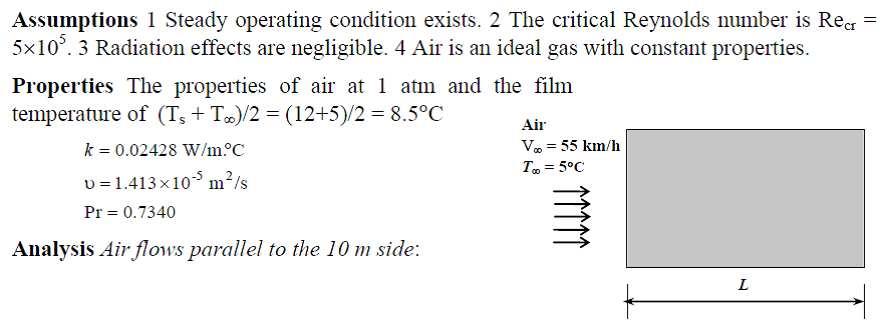
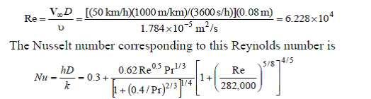
43 2. Wind is blowing parallel to the wall of a house. The temperature and velocity of the air is 5oC& 55 km/hr. Calculate the rate of heat loss from the wall. 43

44 44
45 which is greater than the critical Reynolds number. Thus we have combined laminar and turbulent flow. Using the proper relation for Nusselt number, the average heat transfer coefficient and the heat transfer rate are determined to be 3. Air is flowing over the steam pipe having steam temperature of 90 oc.the velocity and temperature of the air are 7 degree C and 50 km/ hr respectively. Calculate rate of heat loss by the air on the steam pipe Assumptions 1 Steady operating conditions exist. 2 Radiation effects are negligible. 3 Air is an ideal gas with constant properties. 45
46 46
47 4. The components of an electronic system located in a horizontal square duct (20cm 20 cm) is cooled by air flowing over the duct. The velocity and temperature of the air are 200 m/min & 30degree C. Determine the total power rating of the electronic device. 5. Water at 15ºC is to be heated to 65ºC by passing it over a bundle of 4-m-long 1-cmdiameter resistance heater rods maintained at 90ºC. Water approaches the heater rod bundle in normal direction at a mean velocity of 0.8 m/s. The rods arc arranged in-line with longitudinal and transverse pitches of SL = 4 cm and ST = 3 cm. Determine the number of tube rows NL in the flow direction needed to achieve the indicated temperature 47
48 rise. Assumptions 1 steady operating condition exists. 2 The surface temperature of the rods is constant. Properties The properties of water at the mean temperature of (15ºC +65ºC)/2=40ºC 48
49 6. Cooling water available at 10 C is used to condense steam at 30 C in the condenser of a power plant at a rate of 0.15 kg/s by circulating the cooling water through a bank of 5- m-long 1.2-cm-internal-diameter thin copper tubes. Water enters the tubes at a mean velocity of 4 m/s, and leaves at a temperature of 24 C. The tubes are nearly isothermal at 49

50 30 C.Determine the average heat transfer coefficient between the water and the tubes, and the number of tubes needed to achieve the indicated heat transfer rate in the condenser. Assumptions 1 Steady operating conditions exist. 2 The surface temperature of the pipe is constant. 3 The thermal resistance of the pipe is negligible. Properties The properties of water at the average temperature of (10+24)/2=17 C are 50
51 7. Water is to be heated from 10 C to 80 C as it flows through a 2-cm-internal-diameter, 7-m-long tube. The tube is equipped with an electric resistance heater, which provides uniform heating throughout the surface of the tube. The outer surface of the heater is well insulated, so that in steady operation all the heat generated in the heater is transferred to the water in the tube. If the system is to provide hot water at a rate of 8 L/min, determine the power rating of the resistance heater. Also, estimate the inner surface temperature of the pipe at the exit. 51

52 Assumptions 1 Steady flow conditions exist. 2 The surface heat flux is uniform. 3 The inner surfaces of the tube are smooth. Properties The properties of water at the average temperature of (80+10)/ 2 = 45 deg C are 52
53 which is greater than 10,000. Therefore, the flow is turbulent and the entry lengths in this case are roughly 8.Water is boiling in a 12-cm-deep pan with an outer diameter of 25 cm that is placed on top of a stove. The ambient air and the surrounding surfaces are at a temperature of 25 C, and the emissivity of the outer surface of the pan is Assuming the entire pan to be at an average temperature of 98 C, determine the rate of heat loss from the cylindrical side surface of the pan to the surroundings by (a) natural convection and (b) radiation. (c) If 53
54 water is boiling at a rate of 2 kg/h at 100 C, determine the ratio of the heat lost from the side surfaces of the pan to that by evaporation of water. The heat of vaporization of water at 100 C is 2257 kj/kg. Assumptions 1 Steady operating conditions exist. 2 Air is an ideal gas with constant properties. 3 The local atmospheric pressure is 1 atm. Properties The properties of air at 1 atm and the film temperature of (Ts+T )/2 = (98+ 25)/2 = 61.5 deg C are 54
55 55
56 9. Consider a 1.2-m-high and 2-m-wide glass window with a thickness of 6 mm, thermal conductivity k =0.78 W/m C, and emissivity 0.9. The room and the walls that face the window are maintained at 25 C, and the average temperature of the inner surface of the window is measured to be 5 C. If the temperature of the outdoors is 5 C, determine (a) the convection heat transfer coefficient on the inner surface of the window, (b) the rate of total heat transfer through the window, and (c) the combined natural convection and radiation heat transfer coefficient on the outer surface of the window. Is it reasonable to neglect the thermal resistance of the glass in this case? 56
57 Assumptions 1 Steady operating conditions exist. 2 Air is an ideal gas with constant properties. 3 The local atmospheric pressure is 1 atm. Properties The properties of air at 1 atm and the film temperature of (Ts+T )/2 = (5+ 25)/2 = 15deg C are 57
58 58

59 10. Nitrogen at a pressure of 0.1 atm flows over a flat plate with a free stream velocity of 8 m/s. The temperature of the gas is 20 C. The plate temperature is 20 C. Determine the length for the flow to turn turbulent. Assume as critical Reynolds number. Also determine the thickness of thermal and velocity boundary layers and the average convection coefficient for a plate length of 0.3 m. 59
60 60
61 UNIT III - PHASE CHANGE HEAT TRANSFER AND HEAT EXCHANGERS BOILING AND CONDENSATION We know from thermodynamics that when the temperature of a liquid at a specified pressure is raised to the saturation temperature Tsat at that pressure, boiling occurs. 61
62 Likewise, when the temperature of a vapor is lowered to Tsat, condensation occurs. In this chapter we study the rates of heat transfer during such liquid-to-vapor and vapor-toliquid phase transformations. Although boiling and condensation exhibit some unique features, they are considered to be forms of convection heat transfer since they involve fluid motion (such as the rise of the bubbles to the top and the flow of condensate to the bottom). Boiling and condensation differ from other forms of convection in that they depend on the latent heat of vaporization hfg of the fluid and the surface tension _ at the liquid vapor interface, in addition to the properties of the fluid in each phase. Noting that under equilibrium conditions the temperature remains constant during a phase-change process at a fixed pressure, large amounts of heat (due to the large latent heat of vaporization released or absorbed) can be transferred during boiling and condensation essentially at constant temperature. In practice, however, it is necessary to maintain some difference between the surface temperature Ts and Tsat for effective heat transfer. Heat transfer coefficients h associated with boiling and condensation are typically much higher than those encountered in other forms of convection processes that involve a single phase. BOILING HEAT TRANSFER Many familiar engineering applications involve condensation and boiling heat transfer. In a household refrigerator, for example, the refrigerant absorbs heat from the refrigerated space by boiling in the evaporator section and rejects heat to the kitchen air by condensing in the condenser section (the long coils behind the refrigerator). Also, in steam power plants, heat is transferred to the steam in the boiler where water is vaporized, and the waste heat is rejected from the steam in the condenser where the steam is condensed. Some electronic components are cooled by boiling by immersing them in a fluid with an appropriate boiling temperature. Boiling is a liquid-to-vapor phase change process just like evaporation, but there are significant differences between the two. Evaporation occurs at the liquid vapor interface when the vapor pressure is less than the saturation 62
63 pressure of the liquid at a given temperature. Water in a lake at 20 C, for example, will evaporate to air at 20 C and 60 percent relative humidity since the saturation pressure of water at 20 C is 2.3 kpa and the vapor pressure of air at 20 C and 60 percent relative humidity is 1.4 kpa. Other examples of evaporation are the drying of clothes, fruits, and vegetables; the evaporation of sweat to cool the human body; and the rejection of waste heat in wet cooling towers. Note that evaporation involves no bubble formation or bubble motion. 63

64 Boiling, on the other hand, occurs at the solid liquid interface when a liquid is brought into contact with a surface maintained at a temperature Ts sufficiently above the 64
65 saturation temperature Tsat of the liquid (Fig. 10 2). At 1 atm, for example, liquid water in contact with a solid surface at 110 C will boil since the saturation temperature of water at 1 atm is 100 C. The boiling process is characterized by the rapid formation of vapor bubbles at the solid liquid interface that detach from the surface when they reach a certain size and attempt to rise to the free surface of the liquid. When cooking, we do not say water is boiling until we see the bubbles rising to the top. Boiling is a complicated phenomenon because of the large number of variables involved in the process and the complex fluid motion patterns caused by the bubble formation and growth. As a form of convection heat transfer, the boiling heat flux from a solid surface to the fluid is expressed from Newton s law of cooling as 65
 in the presence of it.")
66 Boiling is classified as pool boiling or flow boiling, depending on the presence of bulk fluid motion (Fig. 10 3). Boiling is called pool boiling in the absence of bulk fluid flow and flow boiling (or forced convection boiling) in the presence of it. In pool boiling, the fluid is stationary, and any motion of the fluid is due to natural convection currents and the motion of the bubbles under the influence of buoyancy. The boiling of water in a pan on top of a stove is an example of pool boiling. Pool boiling of a fluid can also be achieved by placing a heating coil in the fluid. In flow boiling, the fluid is forced to move in a heated pipe or over a surface by external means such as a pump. Therefore, flow boiling is always accompanied by other convection effects. 66
 when the temperature of the main body of the liquid is below the saturation temperature Tsat (i.e., the bulk of the liquid is subcooled) and saturated (or bulk) when the temperature of the liquid is equal to Tsat (i.")
67 Pool and flow boiling are further classified as subcooled boiling or saturated boiling, depending on the bulk liquid temperature (Fig. 10 4). Boiling is said to be subcooled (or local) when the temperature of the main body of the liquid is below the saturation temperature Tsat (i.e., the bulk of the liquid is subcooled) and saturated (or bulk) when the temperature of the liquid is equal to Tsat (i.e., the bulk of the liquid is saturated). At the early stages of boiling, the bubbles are confined to a narrow region near the hot surface. This is because the liquid adjacent to the hot surface vaporizes as a result of being heated above its saturation temperature. But these bubbles disappear soon after they move away from the hot surface as a result of heat transfer from the bubbles to the cooler liquid surrounding them. This happens when the bulk of the liquid is at a lower temperature than the saturation temperature. The bubbles serve as energy movers from the hot surface into the liquid body by absorbing heat from the hot surface and releasing it into the liquid as they condense and collapse. Boiling in this case is confined to a region in the locality of the hot surface and is appropriately called local or subcooled boiling. 67

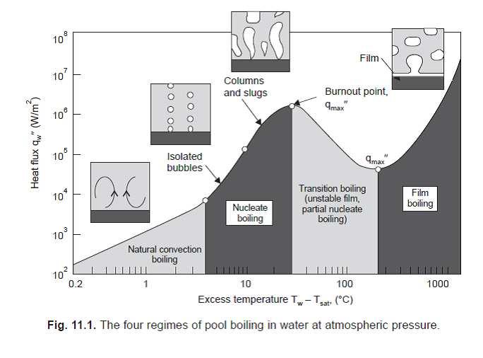
68 When the entire liquid body reaches the saturation temperature, the bubbles start rising to the top. We can see bubbles throughout the bulk of the liquid, POOL BOILING CURVE 68
69 69
70 THE CORRELATIONS OBTAINED FOR NUCLEATE POOL BOILING IS GIVEN BY ROHSENOW (1952). suffix l denotes liquid properties and v denotes vapour properties. 70
71 Where c1 Specific heat of liquid J/kgK ΔT excess temperature C or K, (difference) hfg specific enthalpy of evaporation J/kg Pr Prandtl number of liquid n constant equal to 1 for water and 1.7 for other fluids Csf surface factor shown in tabulation 11.1 and taken as for other cases μ1 dynamic viscosity of the liquid kg/ms or Ns m2 ρ1 density of the liquid kg/m3 ρv density of vapour kg/m3 σ surface tension-liquid-vapour interface N/m g gravitational acceleration m/s2 g0 force conversion factor kgm/ns2 = 1 in SI units. This correlation is the result of a log plot of experimental results with parameters 1. Water at atmospheric pressure (saturation temperature = 100 C) is boiling on a brass surface heated from below. If the surface is at 108 C, determine the heat flux and compare the same with critical heat flux. 71
 the rate of heat transfer to the water and (b) the rate of evaporation of water.")
72 2. Water is to be boiled at atmospheric pressure in a mechanically polished stainless steel pan placed on top of a heating unit. The inner surface of the bottom of the pan is maintained at 108 C. If the diameter of the bottom of the pan is 30 cm, determine (a) the rate of heat transfer to the water and (b) the rate of evaporation of water. SOLUTION Water is boiled at 1 atm pressure on a stainless steel surface. The rate of 72

73 heat transfer to the water and the rate of evaporation of water are to be determined. Assumptions 1 Steady operating conditions exist. 2 Heat losses from the heater and the pan are negligible Properties The properties of water at the saturation temperature of 100 C are surface tension N/m 73

74 CONDENSATION HEAT TRANSFER When saturated vapour comes in contact with a cooler surface, the vapour condenses into liquid. The surface temperature should be lower in this case as compared to the temperature of the vapour. The condensate generally moves down by gravity. If the liquid wets the surface a thin layer of liquids forms over the surface and the film thickness increases along the downward direction. This type of condensation is known as filmwise condensation and this is the type encountered in most practical situations. The film introduces a resistance to heat flow between the surface and the vapour. The heat transfer rate is reduced because of this resistance. If the surface is nonwetting, then droplets form on the surface and these roll down individually. The vapour is in direct contact with the surface over most of the area and heat transfer rates are much higher as there is very little resistance for heat flow between the vapour and the surface. This type is known as dropwise condensation. In practice no surface is found to continue as nonwetting over any length of time. So using the value of heat transfer coefficients assuming dropwise condensation for design purposes is not advisable. 74

75 Saturated steam at a temperature of 65 C condenses on a vertical surface at 55 C. Determine the thickness of the condensate film at locations 0.2, 0.4, 0.6, 0.8, 1 m from the top. Also determine the condensate flow, the film Reynolds number, the local and average values of convective heat transfer coefficients at these locations. Also calculate the condensation numbers. Solution: The property values for liquid should be taken at the film temperature = ( )/2 = 60 C. The liquid property values at 60 C are 75
76 These values at various locations are tabulated below: 76

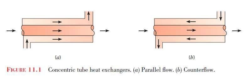
77 HEAT EXCHANGER The process of heat exchange between two fluids that are at different temperatures and separated by a solid wall occurs in many engineering applications. The device used to implement this exchange is termed a heat exchanger, and specific applications may be found in space heating and air-conditioning, power production, waste heat recovery, and chemical processing. In this chapter our objectives are to introduce performance parameters for assessing the efficacy of a heat exchanger and to develop methodologies for designing a heat exchanger or for predicting the performance of an existing exchanger operating under prescribed conditions. Heat Exchanger Types Heat exchangers are typically classified according to flow arrangement and type of construction. The simplest heat exchanger is one for which the hot and cold fluids move in the same or opposite directions in a concentric tube (or double-pipe) construction. In 77
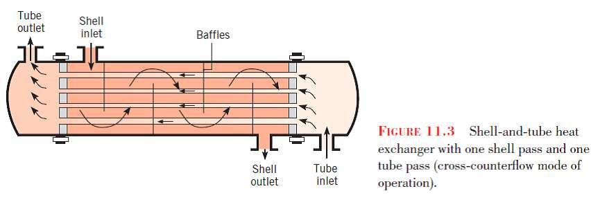
78 the parallel-flowarrangement of Figure 11.1a, the hot and cold fluids enter at the same end, flow in the same direction, and leave at the same end. In the counterflow arrangement of Figure 11.1b, the fluids enter at opposite ends, flow in opposite directions, and leave at opposite ends. Alternatively, the fluids may move in cross flow (perpendicular to each other), as shown by the finned and unfinned tubular heat exchangers of Figure The two configurations are typically differentiated by an idealization that treats fluid motion over the tubes as unmixed or mixed. In Figure 11.2a, the cross-flowing fluid is said to be unmixed because the fins inhibit motion in a direction (y) that is transverse to the main-flow direction (x). In this case the cross-flowing fluid temperature varies with x and y. In contrast, for the unfinned tube bundle of Figure 11.2b, fluid motion, hence mixing, in the transverse direction is possible, and temperature variations are primarily in the main-flow direction. Since the tube flow is unmixed in either heat exchanger, both fluids are unmixed in the finned exchanger, while the crossflowing fluid is mixed and the tube fluid is unmixed in the unfinned exchanger. The nature of the mixing condition influences heat exchanger performance. Another common configuration is the shell-and-tube heat exchanger [1]. Specific forms differ according to the number of shell-and-tube passes, and the simplest form, which involves single tube and shell passes, is shown in Figure Baffles are usually installed to increase the convection coefficient of the shell-side fluid by inducing turbulence and a cross-flow velocity component relative to the tubes. In addition, the baffles physically support the tubes, reducing flow-induced tube vibration. Baffled heat exchangers with one shell pass and two tube passes and with two shell passes and four tube passes are shown in Figures 11.4a and 11.4b, respectively. 78

79 79

80 80

81 Determine the area required in parallel flow heat exchanger to cool oil from 60 C to 30 C using water available at 20 C. The outlet temperature of the water is 26 C. The rate of 81
82 flow of oil is 10 kg/s. The specific heat of the oil is 2200 J/kg K. The overall heat transfer coefficient U = 300 W/m2 K. Compare the area required for a counter flow exchager. Solution: The temperature variation for parallel flow is shown in Fig (a). 82
83 The counter flow arrangement provides more uniform temperature difference along the flow and hence a better rate of heat flow. The counter flow type can also be used to cool or heat over a wider range of temperatures. In the above case by increasing the area or byreducing flow the hot oil can in the limit be cooled to 20 C. Manipulation in the oppositedirection can get the water heated to 60 C. This is not possible in the parallel flow where the exit temperature has to lie somewhere in between the two inlet temperatures. As far as possible counter flow is always used in heat exchanger designs. An economiser in a boiler has flow of water inside the pipes and hot gases on the outside flowing across the pipes. The flow rate of gases is 2,000 tons/hr and the gases are cooled from 390 C to 200 C. The specific heat of the gas is 1005 J/kg K. Water is heated (under pressure) from 100 C to 220 C. Assuming an overall heat transfer coefficient of 35 W/m2 K, determine the area required. Assume that the air flow is mixed. 83
84 84
85 85

86 UNIT IV - Thermal Radiation Introduction This mode of heat transfer defers from the other two modes in that radiation does not require the presence of material medium. Ex: Heat transfer through a vacuum, from Sun to earth, a hot body inside a vacuum. Thermal radiation is that electro magnetic radiation emitted by a body as a result of its temperature which is propagated at the speed of light (310 8 m/s). It is called as the Stefan-Boltzmann Law. The total energy emitted by an ideal radiator or black body per unit time per unit area, E b can be written as Black body radiation or emissive power (W/m 2 ) Stefan Boltzman Constant ( W/m 2 K 4 ) Temperature in K Black body A body at a temperature above absolute zero emits radiation in all directions over a wide range of wave lengths. The amount of radiation emitted from a surface at a given wave 86
87 length depends on the material surface condition and temperature. Therefore different bodies may emit different amount of radiation (Per unit surface area) even when they are at the same temperature. A black body is an ideal surface having the following properties It absorbs all the incident radiation regardless of wave length and direction. No surface can emit more energy than a black body for a given temperature and wave length Radiation emitted by a black body is a function of both wave length and temperature but independent of direction Properties of radiation When radiant energy strikes a material surface, part of the radiation is reflected, part is absorbed and a part is transmitted. If is the fraction reflected, is the fraction absorbed and is the fraction transmitted + + = 1 But for most solid bodies = 0 Emissivity The ratio of the emissing power of a body to the emissive power of the black body at the same temperature is equal to absorptivity of the body. 87


88 The ratio is defined as the emissivity of the body is a function of body temperature and wave length but a grey body is defined as for which absorptivity and emmisivity are independent of wave length. Radiation exchange between surfaces A 2 A 1 Shape factor is defined as the fraction of energy leaving one surface, which reaches the other surface. The figure shows two black surfaces, with areas A 1 and A 2. If F 12 is the fraction of energy leaving surface 1, which reaches surface 2, and if F 21 is the fraction of energy leaving surface 2 which reaches surface 1 The energy leaving surface 1 and reaching surface 2 = E b1 A 1 F 12 The energy leaving surface 2 and reaching surface 2 = E b2 A 2 F 21 The net energy exchange Q 1-2 = E b1 A 1 F 12 -E b2 A 2 F 21 For same temperature Q 1-2 = 0 therefore E b1 A 1 F 12 = E b2 A 2 F 21 88

89 A 1 F 12 = A 2 F 21 In general A i F ij = A j F ji f ij` Geometric factor for surface i to surface j Heat exchange between non-black bodies The calculation of radiation heat transfer between black surfaces is relatively easy since all the radiant energy which strikes a surface is absorbed. The main problem is to find out the shape factors, but once this accomplished, the calculation of heat exchange is very simple. When non-black bodies are involved, the situation is much more complex and for all the energy striking a surface will not be absorbed; part will be reflected back to another heat transfer surface, and part will be reflected back to another heat transfer surface and part may be reflected out of the system entirely. To cope with the situation let us assume the surfaces considered in our analysis are diffusive and uniform in temperature and the reflective and emissive properties are constant over all the surfaces. J i G i E i radiosity, total radiation leaving a surface i per unit time and per unit area. irradiation, total energy incident upon surface i per unit time per unit area. emission, total radiation generated by surface i per unit time per unit area. When no energy transmitted, the radiosity is, J= When trasmitivity is assumed zero, 89
90 So that (1) The net energy leaving the surface (2) Solving (1) and (2) Element representing Surface resistant in radiation network method Now consider he exchange of radiant energy by two surfaces A 1 and A 2, of that total radiation leaving A 1 and reaches A 2 J 1 A 1 F 12 And of that total radiation leaving A 2 and reaches A 1 is J 2 A 2 F 21 The net interchange between the two surfaces is q 1-2 = J 1 A 1 F 12 -J 2 A 2 F 21 But A 1 F 12 = A 2 F 21 90

91 Therefore q 1-2 = (J 1 J 2 ) A 1 F 12 q 1-2 = We may construct the network elements Element representing Space resistant in radiation network method q 1-2 Ex: Two surfaces of area A 1 and A 2 of emissivities and which exchangeheat with each other and nothing else, would be represented by the following circuit diagram. 91
92 A radiation network for three surfaces which see each other and nothing else is E b1 J 2 J 1 J 3 E b3 92
93 E b2 93
94 2. 2. Consider a 4-m 4-m 4-m cubical furnace whose floor and ceiling are black and whose side surfaces are reradiating. The floor and the ceiling of the furnace are maintained at temperatures of 550 K and 1100 K, respectively. Determine the net rate of radiation heat transfer between the floor and the ceiling of the furnace. Assumptions 1 Steady operating condition exist 2 The surfaces are opaque, diffuse, and gray. 3 Convection heat transfer is not considered. 94
95 Properties The emissivities of all surfaces are = 1 since they are black or reradiating. Analysis We consider the ceiling to be surface 1, the floor to be surface 2 and the side surfaces to be surface 3. The furnace can be considered to be three-surface enclosure with a radiation network shown in the figure. We assume that steady-state conditions exist. Since the side surfaces are reradiating, there is no heat transfer through them, and the entire heat lost by the ceiling must be gained by the floor. The view factor from the ceiling to the floor of the furnace is. Then the rate of heat loss from the ceiling can be determined from 95
96 3. A thin aluminum sheet with an emissivity of 0.15 on both sides is placed between two very large parallel plates, which are maintained at uniform temperatures T1 =900 K and T2 =650 K and have emissivities 0.5 and 2,0.8, respectively. Determine the net rate of radiation heat transfer between the two plates per unit surface area of the plates and Compare the result with that without the shield. Assumptions 1 Steady operating conditions exist 2 The surfaces are opaque, diffuse, and gray. 3 Convection heat transfer is not considered. Properties The emissivities of surfaces are given to be emm1 = 0.5, emm2 = 0.8, and emm3 = Analysis The net rate of radiation heat transfer with a thin aluminum shield per unit area of the plates is 96
97 4. Two very large parallel plates are maintained at uniform temperatures of T1=1000 K and T2 = 800 K and have emissivities of 1,2 and 0.2, respectively. It is desired to reduce the net rate of radiation heat transfer between the two plates to one-fifth by placing thin aluminum sheets with anemissivity of 0.15 on both sides between the plates. Determine the number of sheets that need to be inserted. 97
98 Assumptions 1 Steady operating conditions exist 2 The surfaces are opaque, diffuse, and gray. 3 Convection heat transfer is not considered. 98
99 5. T2 = 800 K emm2 = 0.2 T1 = 1000 K emm1 = 0.2 Radiation shields emm3 = 0.15 A2-m-internal-diameter double-walled spherical tank is used to store iced water at 0 C. Each wall is 0.5 cm thick, and the 1.5-cm-thick air space between the two walls of the 99
100 tank is evacuated in order to minimize heat transfer. The surfaces surrounding the evacuated space are polished so that each surface has an emissivity of The temperature of the outer wall of the tank is measured to be 20 C. Assuming the inner wall of the steel tank to be at 0 C, determine (a) the rate of heat transfer to the iced water in the tank and (b) the amount of ice at 0 C that melts during a 24-h period. Assumptions 1 Steady operating conditions exist 2 The surfaces are opaque, diffuse, and gray. Analysis (a) Assuming the conduction resistance s of the walls to be negligible, the rate of heat transfer to the iced water in the tank is determined to be 100

101 UNIT- V- MASS TRANSFER Introduction Mass transfer can result from several different phenomena. There is a mass transfer associated with convection in that mass is transported from one place to another in the flow system. This type of mass transfer occurs on a macroscopic level and is usually treated in the subject of fluid mechanics. When a mixture of gases or liquids is contained such that there exists a concentration gradient of one or more of the constituents across the system, there will be a mass transfer on a microscopic level as the result of diffusion from regions of high concentration to regions of low concentration. In this chapter we are primarily concerned with some of the simple relations that may be used to calculate mass diffusion and their relation to heat transfer. Nevertheless, one must remember that the general subject of mass transfer encompasses both mass diffusion on a molecular scale and the bulk mass transport that may result from a convection process. Not only may mass diffusion occur on a molecular basis, but accelerated diffusion rates will also occur in turbulent-flow systems as a result of the rapid-eddy mixing processes, just as these mixing processes created increased heat transfer and viscous action in 101

102 turbulent flow. Although beyond the scope of our discussion, it is well to mention that mass diffusion may also result from a temperature gradient in a system; this is called thermal diffusion. Similarly, a concentration gradient can give rise to a temperature gradient and a consequent heat transfer. These two effects are termed coupled phenomena and may be treated by the methods of irreversible thermodynamics. Whenever there is concentration difference of a physical quantity in a medium, nature tends to equalize things by forcing a flow from the high to the low concentration region. ANALOGY BETWEEN HEAT AND MASS TRANSFER We have spent a considerable amount of time studying heat transfer, and we could spend just as much time (perhaps more) studying mass transfer. However, the mechanisms of heat and mass transfer are analogous to each other, and thus we can develop an understanding of mass transfer in a short time with little effort by simply drawing parallels between heat and mass transfer. Establishing those bridges between the two seemingly unrelated areas will make it possible to use our heat transfer knowledge to solve mass transfer problems. Alternately, gaining a working knowledge of mass transfer will help us to better understand the heat transfer processes by thinking of heat as a massless substance as they did in the nineteenth century. The short-lived caloric theory of heat is the origin of most heat transfer terminology used today and served its purpose well 102
103 until it was replaced by the kinetic theory. Mass is, in essence, energy since mass and energy can be converted to each other according to Einstein s formula E = mc 2, where c is the speed of light. Therefore, we can look at mass and heat as two different forms of energy and exploit this to advantage without going overboard. PROPERTIES OF MIXTURE In a mixture consisting of two or more materials the mass per unit volume of any component is called mass concentration of that component. If there are two components A and B, then the mass concentration of A is and concentration of B, The total mass concentration is ma + mb, which is also the density of the mixture. Mass concentration can also be expressed in terms of individual and total densities of the mixture i.e., where ρa is the density of A in the mixture and ρ is the density of the mixture. It is more convenient to express the concentration in terms of the molecular weight of the component. Mole fraction Na can be expressed as 103
104 Number of Mole = mass/molecular weight At the temperature T of the mixture then where P a is the partial pressure of A in the mixture and P T is the total pressure of the mixture. C a is the mole concentration of A in the mixture. Also C a + C b = 1 for a two component mixture. DIFFUSION MASS TRANSFER Diffusion mass transfer occurs without macroscopic mass motion or mixing. A lump of sugar dropped into a cup of tea will dissolve by diffusion even if left unstirred. But it will take a long time for the sugar to reach all of the volume in the cup. However it will diffuse into the volume by and by. Consider a chamber in which two different gases at the same pressure and temperature are kept separated by a thin barrier. When the barrier is removed, the gases will begin to diffuse into each others volume. After some time a steady condition of uniform mixture would be reached. This type of diffusion can occur in solids also. The rate in solids will be extremely slow. Diffusion in these situations 104
105 occurs at the molecular level and the governing equations are similar to those in heat conduction where energy transfer occurs at the molecular level. The basic law governing mass transfer at the molecular diffusion level is known as Fick s law. This is similar to the Fourier heat conduction law. In Mass transfer, molal quantities are more convenient to use as compared to mass units, because mass transfer is due to the movement of molecules as discrete quantities. Hence it is convenient to use number of moles, or molar concentration instead of density etc. FICK S LAW OF DIFFUSION The Fick s law can be stated as.1 Where N a > number of moles of a diffusing perpendicular to area A, moles/m 2 sec D ab > Diffusion coefficient or mass diffusivity, m 2 /s, a into b Ca > mole concentration of a moles/m 3 x > diffusion direction The diffusion coefficient is similar to thermal diffusivity, α and momentum diffusivity v. Number of moles multiplied by the molecular mass (or more popularly known as molecular weight) will provide the value of mass transfer in kg/s. Equation 1 can also be written as 2 but this form is not as popular as the more convenient equation (1). The conduction 105
106 equation similar to this is..3 k/ρc is thermal diffusivity α and ρc is the heat capacity (energy density) for unit volume. The derivation of the general mass diffusion equation is similar to that of the general heat conduction equation with C a replacing T and D replacing k/ρc. The general mass diffusion equation for the species A under steady state condition is given by equation (4).. 4 Generation of mass of the species A by chemical reaction is not considered in the equation. However an additive term N a /D on the LHS will take care of this similar to heat generation term q/k. The solutions for this equation are also similar to the solutions of the general conduction equation. However there exist some differences. These are (i) While heat flow is in one direction, the mass of one species flows opposite to the flow of the other component of the mixture. (here two component mixture is considered). (ii) Even while one component alone diffuses under certain circumstances, a bulk flow has to be generated as otherwise a density gradient will be created spontaneously, which is not possible. For example when water evaporates into an air body over water surface, an equal quantity of air cannot enter the water phase. The density gradient created is dispersed by some mixture moving away from the surface maintaining a balance. This is termed as bulk flow. 106
107 The value of Dab for certain combinations of components are available in literature. It can be proved that Dab= Dba. When one molecule of A moves in the x direction, one molecule of B has to move in the opposite direction. Otherwise a macroscopic density gradient will develop, which is not sustainable, (A is area) EQUIMOLAL COUNTER DIFFUSION The total pressure is constant all through the mixture. Hence the difference in partial pressures will be equal. The Fick s equation when integrated for a larger plane volume of thickness L will give Dab equals Dba Where Ca1 and Cb1 are the mole concentrations at face 1 and Ca2 and Cb2 are mole 107
108 concentrations at face 2 which is at a distance L from the first face. When applied to gases, Where Pa1 and Pa2 are partial pressures of component A at x1 and x2 and Ris the universal gas constant in J/kg mol K. T is the temperature in absolute units. The distance should be expressed in metre. The partial pressure variation and diffusion directions are shown in Fig 1. Fig. 1. Partial Pressure variation of components in equimolal counter diffusion. 1. In order to avoid pressure build up ammonia gas at atmospheric pressure in a pipe is vented to atmosphere through a pipe of 3 mm dia and 20 m length. Determine the mass of ammonia diffusing out and mass of air diffusing in per hour. Assume D = m2/s, M = 17 kg/kg mole 108
109 Solution: P NH3 in pipe = 1 atm P NH3 at the outlet = 0 STATIONARY MEDIA WITH SPECIFIED SURFACE CONCENTRATION In the diffusion of gas from containers, there is diffusion of gas from inside to the outside without the metal molecules diffusing into the gas. In these cases the concentration of gas at the surfaces should be known. The solubility of the gas in the surface determines the concentration at the surface. These cases are similar to conduction through the medium. In these cases the temperature potential in conduction is replaced by concentration potential (Ca1 Ca2) for component A. The flow rate can be obtained as in the case of conduction. Na = (Ca1 Ca2)/R. Where R is the resistance of diffusion. The resistance in the case of plane wall is 109
110 For hollow cylindrical configuration. These equations can be derived from the general equation in Cartesian, cylindrical and spherical coordinate systems. 2. Hydrogen stored in a vessel diffuses through the steel wall of 20 mm thickness. The molar concentration at the inner surface is 2 kg mol/m 3. At the other surface it is zero. Assuming plane wall condition and Dab = m 2 /s, determine the mass of hydrogen diffused per 1 m 2. DIFFUSION OF ONE COMPONENT INTO A STATIONARYCOMPONENT OR 110
111 UNIDIRECTIONAL DIFFUSION In this case one of the components diffuses while the other is stationary. For steady conditions the mass diffused should be absorbed continuously at the boundary. In certain cases this is not possible. The popular example is water evaporating into air. In this case, as mentioned earlier, a bulk motion replaces the air tending to accumulate at the interface without being absorbed, causing an increase in the diffusion rate. The diffusion equation for gases can be derived as (with a as the diffusing medium and P = total pressure) For liquids (considering a as diffusing medium) 1.Oxygen is diffusing in a mixture of oxygen-nitrogen at 1 std atm, 25C. Concentration of oxygen at planes 2 mm apart are 10 and 20 volume % respectively. Nitrogen is nondiffusing. Derive the appropriate expression to calculate the flux oxygen. Define units of each term clearly. Calculate the flux of oxygen. Diffusivity of oxygen in nitrogen = 1.89 * 10 5 m 2 /sec. Solution: Given: 111
112 D AB = 1.89 * 10 5 m 2 /sec P t = 1 atm = * 10 5 N/m 2 T = 25C = = 298 K z = 2 mm = m P A1 = 0.2 * 1 = 0.2 atm (From Ideal gas law and additive pressure rule) P A2 = 0.1 * 1 = 0.1 atm Substituting these in equation (6) = 4.55 * 10 5 kmol/m 2.sec 2.A vertical glass tube 3 mm in diameter is filled with liquid toluene to a depth of 20mm from the top openend. After 275 hrs at 39.4 C and a total pressure of 760 mm Hg the level has dropped to 80 mm from the top. Calculate the value of diffusivity. Given Data: vapor pressure of toluene at 39.4C = 7.64 kn / m 2, density of liquid toluene = 850 kg/m 3 Molecular weight of toluene = 92 (C 6 H 6 CH 3 ) 112
113 = k mol /m 3 Therefore = * 10 3 ( ) = * 10-6 m 2 /sec. 3.Methane diffuses at steady state through a tube containing helium. At point 1 the partial pressure of methane is p A1 = 55 kpa and at point 2, 0.03 m apart P A2 = 15 KPa. The total pressure is kpa, and the temperature is 298 K. At this pressure and temperature, the value of diffusivity is 6.75 * 10 5 m 2 /sec. calculate the flux of CH 4 at steady state for equimolar counter diffusion. Calculate the partial pressure at a point 0.02 m apart from point 1. Calculation: For steady state equimolar counter diffusion, molar flux is given by Therefore; 113
114 And from (1), partial pressure at 0.02 m from point 1 is: p A = kpa. 4.In a gas mixture of hydrogen and oxygen, steady state equimolar counter diffusion is occurring at a total pressure of 100 kpa and temperature of 20C. If the partial pressures of oxygen at two planes 0.01 m apart, and perpendicular to the direction of diffusion are 15 kpa and 5 kpa, respectively and the mass diffusion flux of oxygen in the mixture is 1.6 * 10 5 kmol/m 2.sec, calculate the molecular diffusivity for the system. Solution: For equimolar counter current diffusion: (1) N A = molar flux of A (1.6* 10 5 kmol/m 2.sec): D AB = molecular diffusivity of A in B R = Universal gas constant (8.314 kj/kmol.k) T = Temperature in absolute scale ( = 293 K) z = distance between two measurement planes 1 and 2 (0.01 m) 114

115 P A1 = partial pressure of A at plane 1 (15 kpa); and P A2 = partial pressure of A at plane 2 (5 kpa) Substituting these in equation (1) Therefore, D AB = * 10 5 m 2 /sec 5.A tube 1 cm in inside diameter that is 20 cm long is filled with Co 2 and H 2 at a total pressure of 2 atm at 0C. The diffusion coefficient of the Co 2 H 2 system under these conditions is cm 2 /sec. If the partial pressure of Co 2 is 1.5 atm at one end of the tube and 0.5 atm at the other end, find the rate of diffusion for: steady state equimolar counter diffusion (N A = -N B ) steady state counter diffusion where N B = N A, and steady state diffusion of Co 2 through stagnant H 2 (N B = 0) Given: D AB = cm 2 /sec = * 10 4 m 2 /sec ; T = 0C = 273 k 115
116 Rate of diffusion = N A S Where S is surface area Therefore rate of diffusion = * 10-6 * r 2 = * 10 6 *(0.5* 10 2 ) 2 = * k mol/sec = * 10 3 mol/hr. ii) given: N B = N A Therefore for constant N A and C 116

117 (2) Given: Substituting these in equation (2), 117
118 Rate of diffusion = N A S = * 10 6 * * (0.5 * 10 2 ) 2 = 5.52 * kmol/sec = * 10 3 mol/hr. iii) Given:N B = 0 Therefore 118

 and the concentration at some arbitrarily defined point in the fluid")
119 Rate of diffusion = **(0.5* 10 2 ) 2 = Kmol / sec = mol/hr CONVECTIVE MASS TRANSFER In the study of convective heat transfer, the heat flux is connected to heat transfer coefficient as (4.1) The analogous situation in mass transfer is handled by an equation of the form (4.2) The molar flux N A is measured relative to a setof axes fixed in space. The driving force is the difference between the concentration at the phase boundary, C AS (a solid surface or a fluid interface) and the concentration at some arbitrarily defined point in the fluid medium, C A. The convective mass transfer coefficient k C is a function of geometry of the system and the velocity and properties of the fluid similar to the heat transfer coefficient, h. Significant Parameters in Convective Mass Transfer Dimensionless parameters are often used to correlate convective transfer data. In momentum transfer Reynolds number and friction factor play a major role. In the 119

120 correlation of convective heat transfer data, Prandtl and Nusselt numbers are important. Some of the same parameters, along with some newly defined dimensionless numbers, will be useful in the correlation of convective mass-transfer data. The molecular diffusivities of the three transport process (momentum, heat and mass) have been defined as: (4.3) (4.4) and (4.5) It can be shown that each of the diffusivities has the dimensions of L 2 / t, hence, a ratio of any of the two of these must be dimensionless. The ratio of the molecular diffusivity of momentum to the molecular diffusivity of heat (thermal diffusivity) is designated as the Prandtl Number (4.6) The analogous number in mass transfer is Schmidt number given as 120
121 (4.7) The ratio of the molecular diffusivity of heat to the molecular diffusivity of mass is designated the Lewis Number, and is given by (4.8) Lewis number is encountered in processes involving simultaneous convective transfer of mass and energy. Let us consider the mass transfer of solute A from a solid to a fluid flowing past the surface of the solid. For such a case, the mass transfer between the solid surface and the fluid may be written as (4.1 a) Since the mass transfer at the surface is by molecular diffusion, the mass transfer may also described by (4.9) When the boundary concentration, C As is constant, equation (4.9) may be written as (4.10) 121
122 Equation (4.1a) and (4.10) may be equated, since they define the same flux of component A leaving the surface and entering the fluid (4.11) This relation may be rearranged into the following form: (4.12) Multiplying both sides of equation(4.12) by a characteristic length, L we obtain the following dimensionless expression: (4.13) The right hand side of equation (4.13) is the ratio of the concentration gradient at the surface to an overall or reference concentration gradient; accordingly, it may be considered as the ratio of molecular mass-transport resistance to the convective masstransport resistance of the fluid. This ratio is generally known as the Sherwood number, Sh and analogous to the Nusselt number Nu, in heat transfer. Application of Dimensionless Analysis to Mass Transfer One of the method of obtaining equations for predicting mass-transfer coefficients is the use of dimensionless analysis. Dimensional analysis predicts the various dimensionless 122
123 parameters which are helpful in correlating experimental data. There are two important mass transfer processes, which we shall consider, the transfer of mass into a steam flowing under forced convection and the transfer of mass into a phase which is moving as the result of natural convection associated with density gradients. 6. A stream of air at 100 kpa pressure and 300 K is flowing on the top surface of a thin flat sheet of solid naphthalene of length 0.2 m with a velocity of 20 m/sec. The other data are: Mass diffusivity of naphthalene vapor in air = 6 * 10 6 m 2 /sec Kinematic viscosity of air = 1.5 * 10 5 m 2.sc Concentration of naphthalene at the air-solid naphthalene interface = 1 * 10 5 kmol/m 3 Calculate: the overage mass transfer coefficient over the flat plate the rate of loss of naphthalene from the surface per unit width Note: For heat transfer over a flat plate, convective heat transfer coefficient for laminar flow can be calculated by the equation. you may use analogy between mass and heat transfer. Solution: Given: Correlation for heat transfer 123

124 The analogous relation for mass transfer is (1) where Sh = Sherwood number = kl/d AB Re L = Reynolds number = L/ Sc = Schmidt number = /( D AB ) k = overall mass transfer coefficient L = length of sheet D AB = diffusivity of A in B = velocity of air = viscosity of air = density of air, and / = kinematic viscosity of air. Substituting for the known quantities in equation (1) k = m/sec 124
125 Rate of loss of naphthalene = k (C Ai C A ) = (1* ) = * 10 7 kmol/m 2 sec Rate of loss per meter width = (1.4024* 10 7 )(0.2) = * 10 8 kmol/m.sec = gmol/m.hr. 7. The mass flux from a 5 cm diameter naphthalene ball placed in stagnant air at 40C and atmospheric pressure, is 1.47 * 10 3 mol/m 2. sec. Assume the vapor pressure of naphthalene to be 0.15 atm at 40C and negligible bulk concentration of naphthalene in air. If air starts blowing across the surface of naphthalene ball at 3 m/s by what factor will the mass transfer rate increase, all other conditions remaining the same? For spheres : Sh = (Re) 0.5 (Sc) 0.33 Where Sh is the Sherwood number and Sc is the Schmids number. The viscosity and density of air are 1.8 * 10 5 kg/m.s and kg/m 3, respectively and the gas constant is cm 3. atm/mol.k. Given: 125
126 = cm/sec k c = * 10 4 m/sec (3) Estimation of D AB : From (2), (since v = 0) Therefore D AB = * 10 6 m 2 /sec. And 7946 k c = * (96.74) * (1.361) k c = m/sec (4) 126


127 Therefore, rate of mass transfer increases by 40.5 times the initial conditions. 8.A solid disc of benzoic acid 3 cm in diameter is spin at 20 rpm and 25C. Calculate the rate of dissolution in a large volume of water. Diffusivity of benzoic acid in water is 1.0 * 10 5 cm 2 /sec, and solubility is g/cc. The following mass transfer correlation is applicable: Sh = 0.62 Re ½ Sc 1/3 Where and is the angular speed in radians/time. Given: Sh = 0.62 Re ½ Sc 1/3 (i.e.) (3) 1 rotation = 2 radian Therefore 20 rotation per minute = 20 * 2 radian/min From (3), For water = 1 g/cm 3 = 1 centipoise = 0.01 g/cm.sec. 127
Principles of Convection
 Principles of Convection Point Conduction & convection are similar both require the presence of a material medium. But convection requires the presence of fluid motion. Heat transfer through the: Solid
If there is convective heat transfer from outer surface to fluid maintained at T W.
 Heat Transfer 1. What are the different modes of heat transfer? Explain with examples. 2. State Fourier s Law of heat conduction? Write some of their applications. 3. State the effect of variation of temperature
UNIT II CONVECTION HEAT TRANSFER
 UNIT II CONVECTION HEAT TRANSFER Convection is the mode of heat transfer between a surface and a fluid moving over it. The energy transfer in convection is predominately due to the bulk motion of the fluid
C ONTENTS CHAPTER TWO HEAT CONDUCTION EQUATION 61 CHAPTER ONE BASICS OF HEAT TRANSFER 1 CHAPTER THREE STEADY HEAT CONDUCTION 127
 C ONTENTS Preface xviii Nomenclature xxvi CHAPTER ONE BASICS OF HEAT TRANSFER 1 1-1 Thermodynamics and Heat Transfer 2 Application Areas of Heat Transfer 3 Historical Background 3 1-2 Engineering Heat
Convection. forced convection when the flow is caused by external means, such as by a fan, a pump, or atmospheric winds.
 Convection The convection heat transfer mode is comprised of two mechanisms. In addition to energy transfer due to random molecular motion (diffusion), energy is also transferred by the bulk, or macroscopic,
HEAT TRANSFER 1 INTRODUCTION AND BASIC CONCEPTS 5 2 CONDUCTION
 HEAT TRANSFER 1 INTRODUCTION AND BASIC CONCEPTS 5 2 CONDUCTION 11 Fourier s Law of Heat Conduction, General Conduction Equation Based on Cartesian Coordinates, Heat Transfer Through a Wall, Composite Wall
Heat and Mass Transfer Unit-1 Conduction
 1. State Fourier s Law of conduction. Heat and Mass Transfer Unit-1 Conduction Part-A The rate of heat conduction is proportional to the area measured normal to the direction of heat flow and to the temperature
Chapter 3 NATURAL CONVECTION
 Fundamentals of Thermal-Fluid Sciences, 3rd Edition Yunus A. Cengel, Robert H. Turner, John M. Cimbala McGraw-Hill, 2008 Chapter 3 NATURAL CONVECTION Mehmet Kanoglu Copyright The McGraw-Hill Companies,
Chapter 10: Boiling and Condensation 1. Based on lecture by Yoav Peles, Mech. Aero. Nuc. Eng., RPI.
 Chapter 10: Boiling and Condensation 1 1 Based on lecture by Yoav Peles, Mech. Aero. Nuc. Eng., RPI. Objectives When you finish studying this chapter, you should be able to: Differentiate between evaporation
Thermal Systems. What and How? Physical Mechanisms and Rate Equations Conservation of Energy Requirement Control Volume Surface Energy Balance
 Introduction to Heat Transfer What and How? Physical Mechanisms and Rate Equations Conservation of Energy Requirement Control Volume Surface Energy Balance Thermal Resistance Thermal Capacitance Thermal
TOPIC 2 [A] STEADY STATE HEAT CONDUCTION
![TOPIC 2 [A] STEADY STATE HEAT CONDUCTION](/thumbs/96/128741039.jpg "TOPIC 2 [A] STEADY STATE HEAT CONDUCTION") TOPIC 2 [A] STEADY STATE HEAT CONDUCTION CLASS TUTORIAL 1. The walls of a refrigerated truck consist of 1.2 mm thick steel sheet (k=18 W/m-K) at the outer surface, 22 mm thick cork (k=0.04 W/m-K) on the
TOPIC 2 [A] STEADY STATE HEAT CONDUCTION CLASS TUTORIAL 1. The walls of a refrigerated truck consist of 1.2 mm thick steel sheet (k=18 W/m-K) at the outer surface, 22 mm thick cork (k=0.04 W/m-K) on the
PHYSICAL MECHANISM OF CONVECTION
 Tue 8:54:24 AM Slide Nr. 0 of 33 Slides PHYSICAL MECHANISM OF CONVECTION Heat transfer through a fluid is by convection in the presence of bulk fluid motion and by conduction in the absence of it. Chapter
We know from thermodynamics that when the temperature of a liquid
 cen58933_ch10.qxd 9/4/2002 12:37 PM Page 515 BOILING AND CONDENSATION CHAPTER 10 We know from thermodynamics that when the temperature of a liquid at a specified pressure is raised to the saturation temperature
Chapter 1 INTRODUCTION AND BASIC CONCEPTS
 Heat and Mass Transfer: Fundamentals & Applications 5th Edition in SI Units Yunus A. Çengel, Afshin J. Ghajar McGraw-Hill, 2015 Chapter 1 INTRODUCTION AND BASIC CONCEPTS Mehmet Kanoglu University of Gaziantep
SHRI RAMSWAROOP MEMORIAL COLLEGE OF ENGG. & MANAGEMENT B.Tech. [SEM V (ME-51, 52, 53, 54)] QUIZ TEST-1 (Session: )
![SHRI RAMSWAROOP MEMORIAL COLLEGE OF ENGG. & MANAGEMENT B.Tech. [SEM V (ME-51, 52, 53, 54)] QUIZ TEST-1 (Session: )](/thumbs/78/78353407.jpg "SHRI RAMSWAROOP MEMORIAL COLLEGE OF ENGG. & MANAGEMENT B.Tech. [SEM V (ME-51, 52, 53, 54)] QUIZ TEST-1 (Session: )") QUIZ TEST-1 Time: 1 Hour HEAT AND MASS TRANSFER Note: All questions are compulsory. Q1) The inside temperature of a furnace wall ( k=1.35w/m.k), 200mm thick, is 1400 0 C. The heat transfer coefficient
QUIZ TEST-1 Time: 1 Hour HEAT AND MASS TRANSFER Note: All questions are compulsory. Q1) The inside temperature of a furnace wall ( k=1.35w/m.k), 200mm thick, is 1400 0 C. The heat transfer coefficient
PHYSICAL MECHANISM OF NATURAL CONVECTION
 1 NATURAL CONVECTION In this chapter, we consider natural convection, where any fluid motion occurs by natural means such as buoyancy. The fluid motion in forced convection is quite noticeable, since a
Heat and Mass Transfer Prof. S.P. Sukhatme Department of Mechanical Engineering Indian Institute of Technology, Bombay
 Heat and Mass Transfer Prof. S.P. Sukhatme Department of Mechanical Engineering Indian Institute of Technology, Bombay Lecture No. 18 Forced Convection-1 Welcome. We now begin our study of forced convection
Principles of Food and Bioprocess Engineering (FS 231) Problems on Heat Transfer
 Problems on Heat Transfer") Principles of Food and Bioprocess Engineering (FS 1) Problems on Heat Transfer 1. What is the thermal conductivity of a material 8 cm thick if the temperature at one end of the product is 0 C and the temperature
Principles of Food and Bioprocess Engineering (FS 1) Problems on Heat Transfer 1. What is the thermal conductivity of a material 8 cm thick if the temperature at one end of the product is 0 C and the temperature
So far, we have considered conduction, which is the mechanism of heat
 cen58933_ch06.qxd 9/4/2002 12:05 PM Page 333 FUNDAMENTALS OF CONVECTION CHAPTER 6 So far, we have considered conduction, which is the mechanism of heat transfer through a solid or a quiescent fluid. We
MYcsvtu Notes HEAT TRANSFER BY CONVECTION
 www.mycsvtunotes.in HEAT TRANSFER BY CONVECTION CONDUCTION Mechanism of heat transfer through a solid or fluid in the absence any fluid motion. CONVECTION Mechanism of heat transfer through a fluid in
Convective Mass Transfer
 Convective Mass Transfer Definition of convective mass transfer: The transport of material between a boundary surface and a moving fluid or between two immiscible moving fluids separated by a mobile interface
S.E. (Chemical) (Second Semester) EXAMINATION, 2011 HEAT TRANSFER (2008 PATTERN) Time : Three Hours Maximum Marks : 100
 (Second Semester) EXAMINATION, 2011 HEAT TRANSFER (2008 PATTERN) Time : Three Hours Maximum Marks : 100") Total No. of Questions 12] [Total No. of Printed Pages 7 [4062]-186 S.E. (Chemical) (Second Semester) EXAMINATION, 2011 HEAT TRANSFER (2008 PATTERN) Time : Three Hours Maximum Marks : 100 N.B. : (i) Answers
Total No. of Questions 12] [Total No. of Printed Pages 7 [4062]-186 S.E. (Chemical) (Second Semester) EXAMINATION, 2011 HEAT TRANSFER (2008 PATTERN) Time : Three Hours Maximum Marks : 100 N.B. : (i) Answers
S.E. (Chemical) (Second Semester) EXAMINATION, 2012 HEAT TRANSFER (2008 PATTERN) Time : Three Hours Maximum Marks : 100
 (Second Semester) EXAMINATION, 2012 HEAT TRANSFER (2008 PATTERN) Time : Three Hours Maximum Marks : 100") Total No. of Questions 12] [Total No. of Printed Pages 7 Seat No. [4162]-187 S.E. (Chemical) (Second Semester) EXAMINATION, 2012 HEAT TRANSFER (2008 PATTERN) Time : Three Hours Maximum Marks : 100 N.B.
Total No. of Questions 12] [Total No. of Printed Pages 7 Seat No. [4162]-187 S.E. (Chemical) (Second Semester) EXAMINATION, 2012 HEAT TRANSFER (2008 PATTERN) Time : Three Hours Maximum Marks : 100 N.B.
Introduction to Heat Transfer
 Question Bank CH302 Heat Transfer Operations Introduction to Heat Transfer Question No. 1. The essential condition for the transfer of heat from one body to another (a) Both bodies must be in physical
Chapter 7: External Forced Convection. Dr Ali Jawarneh Department of Mechanical Engineering Hashemite University
 Chapter 7: External Forced Convection Dr Ali Jawarneh Department of Mechanical Engineering Hashemite University Objectives When you finish studying this chapter, you should be able to: Distinguish between
Chapter 9 NATURAL CONVECTION
 Heat and Mass Transfer: Fundamentals & Applications Fourth Edition in SI Units Yunus A. Cengel, Afshin J. Ghajar McGraw-Hill, 2011 Chapter 9 NATURAL CONVECTION PM Dr Mazlan Abdul Wahid Universiti Teknologi
Introduction to Heat and Mass Transfer. Week 5
 Introduction to Heat and Mass Transfer Week 5 Critical Resistance Thermal resistances due to conduction and convection in radial systems behave differently Depending on application, we want to either maximize
Convection Heat Transfer. Introduction
 Convection Heat Transfer Reading Problems 12-1 12-8 12-40, 12-49, 12-68, 12-70, 12-87, 12-98 13-1 13-6 13-39, 13-47, 13-59 14-1 14-4 14-18, 14-24, 14-45, 14-82 Introduction Newton s Law of Cooling Controlling
Experiment 1. Measurement of Thermal Conductivity of a Metal (Brass) Bar
 Bar") Experiment 1 Measurement of Thermal Conductivity of a Metal (Brass) Bar Introduction: Thermal conductivity is a measure of the ability of a substance to conduct heat, determined by the rate of heat flow
Experiment 1 Measurement of Thermal Conductivity of a Metal (Brass) Bar Introduction: Thermal conductivity is a measure of the ability of a substance to conduct heat, determined by the rate of heat flow
Fatima
 Fatima QUESTION BANK DEPARTMENT: MECH SEMESTER: IV SUBJECT CODE / Name: ME 2251/HEAT AND MASS TRANSFER UNIT I: CONDUCTION PART -A (2 Marks) 1. What is Fourier's Law of heat conduction? (May 05, May 06,
Mechanical Engineering. Postal Correspondence Course HEAT TRANSFER. GATE, IES & PSUs
 Heat Transfer-ME GATE, IES, PSU 1 SAMPLE STUDY MATERIAL Mechanical Engineering ME Postal Correspondence Course HEAT TRANSFER GATE, IES & PSUs Heat Transfer-ME GATE, IES, PSU 2 C O N T E N T 1. INTRODUCTION
Chapter 11. Energy in Thermal Processes
 Chapter 11 Energy in Thermal Processes Energy Transfer When two objects of different temperatures are placed in thermal contact, the temperature of the warmer decreases and the temperature of the cooler
MECHANISM BEHIND FREE /NATURAL CONVECTION
 CONVECTIVE HEAT TRANSFER By: Prof K. M. Joshi, Assi. Professor, MED, SSAS Institute of Technology, Surat. MECHANISM BEHIND FREE /NATURAL CONVECTION The stagnate layer of fluid in immediate vicinity of
An-Najah National University Civil Engineering Department. Fluid Mechanics. Chapter 1. General Introduction
 1 An-Najah National University Civil Engineering Department Fluid Mechanics Chapter 1 General Introduction 2 What is Fluid Mechanics? Mechanics deals with the behavior of both stationary and moving bodies
Examination Heat Transfer
 Examination Heat Transfer code: 4B680 date: 17 january 2006 time: 14.00-17.00 hours NOTE: There are 4 questions in total. The first one consists of independent sub-questions. If necessary, guide numbers
HEAT TRANSFER. PHI Learning PfcO too1. Principles and Applications BINAY K. DUTTA. Delhi Kolkata. West Bengal Pollution Control Board
 HEAT TRANSFER Principles and Applications BINAY K. DUTTA West Bengal Pollution Control Board Kolkata PHI Learning PfcO too1 Delhi-110092 2014 Contents Preface Notations ix xiii 1. Introduction 1-8 1.1
INSTRUCTOR: PM DR MAZLAN ABDUL WAHID
 SMJ 4463: HEAT TRANSFER INSTRUCTOR: PM DR MAZLAN ABDUL WAHID http://www.fkm.utm.my/~mazlan TEXT: Introduction to Heat Transfer by Incropera, DeWitt, Bergman, Lavine 5 th Edition, John Wiley and Sons DR
Unit B-4: List of Subjects
 ES312 Energy Transfer Fundamentals Unit B: First Law of Thermodynamics ROAD MAP... B-1: The Concept of Energy B-2: Work Interactions B-3: First Law of Thermodynamics B-4: Heat Transfer Fundamentals Unit
Chapter 5. Mass and Energy Analysis of Control Volumes. by Asst. Prof. Dr.Woranee Paengjuntuek and Asst. Prof. Dr.Worarattana Pattaraprakorn
 Chapter 5 Mass and Energy Analysis of Control Volumes by Asst. Prof. Dr.Woranee Paengjuntuek and Asst. Prof. Dr.Worarattana Pattaraprakorn Reference: Cengel, Yunus A. and Michael A. Boles, Thermodynamics:
A drop forms when liquid is forced out of a small tube. The shape of the drop is determined by a balance of pressure, gravity, and surface tension
 A drop forms when liquid is forced out of a small tube. The shape of the drop is determined by a balance of pressure, gravity, and surface tension forces. 2 Objectives 3 i i 2 1 INTRODUCTION Property:
THERMAL DESIGN OF FALLING FILM EVAPORATOR
 YMCA Institute of Engineering, Faridabad, Haryana.., Dec 9-10, 006. THERMAL DESIGN OF FALLING FILM EVAPORATOR Ashik Patel 1, Manish purohit, C. R. Sonawane 3 1, Department of Mechanical Engineering Students,
Level 7 Post Graduate Diploma in Engineering Heat and mass transfer
 9210-221 Level 7 Post Graduate Diploma in Engineering Heat and mass transfer 0 You should have the following for this examination one answer book non programmable calculator pen, pencil, drawing instruments
Applied Thermodynamics HEAT TRANSFER. Introduction What and How?
 LANDMARK UNIVERSITY, OMU-ARAN LECTURE NOTE: 3 COLLEGE: COLLEGE OF SCIENCE AND ENGINEERING DEPARTMENT: MECHANICAL ENGINEERING PROGRAMME: ENGR. ALIYU, S.J Course code: MCE 311 Course title: Applied Thermodynamics
: HEAT TRANSFER & EVAPORATION COURSE CODE : 4072 COURSE CATEGORY : B PERIODS/ WEEK : 5 PERIODS/ SEMESTER : 70 CREDIT : 5 TIME SCHEDULE
 COURSE TITLE : HEAT TRANSFER & EVAPORATION COURSE CODE : 4072 COURSE CATEGORY : B PERIODS/ WEEK : 5 PERIODS/ SEMESTER : 70 CREDIT : 5 TIME SCHEDULE MODULE TOPIC PERIODS 1 Conduction,Fourier law,variation
Chapter 3: Steady Heat Conduction. Dr Ali Jawarneh Department of Mechanical Engineering Hashemite University
 Chapter 3: Steady Heat Conduction Dr Ali Jawarneh Department of Mechanical Engineering Hashemite University Objectives When you finish studying this chapter, you should be able to: Understand the concept
HEAT TRANSFER BY CONVECTION. Dr. Şaziye Balku 1
 HEAT TRANSFER BY CONVECTION Dr. Şaziye Balku 1 CONDUCTION Mechanism of heat transfer through a solid or fluid in the absence any fluid motion. CONVECTION Mechanism of heat transfer through a fluid in the
HEAT AND MASS TRANSFER. Subject Code : 10ME63 IA Marks : 25 Hours/Week : 04 Exam Hours : 03 Total Hours : 52 Exam Marks : 100
 HEAT AND MASS TRANSFER Subject Code : 10ME63 IA Marks : 25 Hours/Week : 04 Exam Hours : 03 Total Hours : 52 Exam Marks : 100 PART A UNIT - 1 Introductory Concepts and Definitions: Modes of heat transfer:
Chapter 10: Steady Heat Conduction
 Chapter 0: Steady Heat Conduction In thermodynamics, we considered the amount of heat transfer as a system undergoes a process from one equilibrium state to another hermodynamics gives no indication of
Chapter 3. Basic Principles. Contents
 Chapter 3. Basic Principles Contents 3.1 Introduction 3.2 Heat 3.3 Sensible Heat 3.4 Latent Heat 3.5 Evaporative Cooling 3.6 Convection 3.7 Transport 3.8 Energy Transfer Mediums 3.9 Radiation 3.10 Greenhouse
Chapter 2 HEAT CONDUCTION EQUATION
 Heat and Mass Transfer: Fundamentals & Applications 5th Edition in SI Units Yunus A. Çengel, Afshin J. Ghajar McGraw-Hill, 2015 Chapter 2 HEAT CONDUCTION EQUATION Mehmet Kanoglu University of Gaziantep
ELEC9712 High Voltage Systems. 1.2 Heat transfer from electrical equipment
 ELEC9712 High Voltage Systems 1.2 Heat transfer from electrical equipment The basic equation governing heat transfer in an item of electrical equipment is the following incremental balance equation, with
Liquids and solids are essentially incompressible substances and the variation of their density with pressure is usually negligible.
 Properties of Fluids Intensive properties are those that are independent of the mass of a system i.e. temperature, pressure and density. Extensive properties are those whose values depend on the size of
Ministry of Higher Education And Scientific Research. University Of Technology Chemical Engineering Department. Heat Transfer
 Ministry of Higher Education And Scientific Research University Of Technology Heat Transfer Third Year By Dr.Jamal Al-Rubeai 2008-2009 Heat Transfer 1. Modes of Heat Transfer: Conduction, Convection and
Overall Heat Transfer Coefficient
 Overall Heat Transfer Coefficient A heat exchanger typically involves two flowing fluids separated by a solid wall. Heat is first transferred from the hot fluid to the wall by convection, through the wall
DEPARTMENT OF MECHANICAL ENGINEERING. ME 6502 Heat and Mass Transfer III YEAR-V SEMESTER
 ME650 HEAT AND MASS TRNSFER MARKS & 16 MARKS QUESTION AND ANSWER ME 650 Heat and Mass Transfer III YEAR-V SEMESTER NAME :. REG.NO :. BRANCH :... YEAR & SEM :. 1 ME650 HEAT AND MASS TRNSFER MARKS & 16 MARKS
Thermal Effects. IGCSE Physics
 Thermal Effects IGCSE Physics Starter What is the difference between heat and temperature? What unit is thermal energy measured in? And what does it depend on? In which direction does heat flow? Heat (Thermal
Outlines. simple relations of fluid dynamics Boundary layer analysis. Important for basic understanding of convection heat transfer
 Forced Convection Outlines To examine the methods of calculating convection heat transfer (particularly, the ways of predicting the value of convection heat transfer coefficient, h) Convection heat transfer
COVENANT UNIVERSITY NIGERIA TUTORIAL KIT OMEGA SEMESTER PROGRAMME: MECHANICAL ENGINEERING
 COVENANT UNIVERSITY NIGERIA TUTORIAL KIT OMEGA SEMESTER PROGRAMME: MECHANICAL ENGINEERING COURSE: MCE 524 DISCLAIMER The contents of this document are intended for practice and leaning purposes at the
Chapter 2 HEAT CONDUCTION EQUATION
 Heat and Mass Transfer: Fundamentals & Applications Fourth Edition Yunus A. Cengel, Afshin J. Ghajar McGraw-Hill, 2011 Chapter 2 HEAT CONDUCTION EQUATION Mehmet Kanoglu University of Gaziantep Copyright
Chapter 11: Heat Exchangers. Dr Ali Jawarneh Department of Mechanical Engineering Hashemite University
 Chapter 11: Heat Exchangers Dr Ali Jawarneh Department of Mechanical Engineering Hashemite University Objectives When you finish studying this chapter, you should be able to: Recognize numerous types of
heat transfer process where a liquid undergoes a phase change into a vapor (gas)
") Two-Phase: Overview Two-Phase two-phase heat transfer describes phenomena where a change of phase (liquid/gas) occurs during and/or due to the heat transfer process two-phase heat transfer generally considers
Two-Phase: Overview Two-Phase two-phase heat transfer describes phenomena where a change of phase (liquid/gas) occurs during and/or due to the heat transfer process two-phase heat transfer generally considers
ME 331 Homework Assignment #6
 ME 33 Homework Assignment #6 Problem Statement: ater at 30 o C flows through a long.85 cm diameter tube at a mass flow rate of 0.020 kg/s. Find: The mean velocity (u m ), maximum velocity (u MAX ), and
10 minutes reading time is allowed for this paper.
 EGT1 ENGINEERING TRIPOS PART IB Tuesday 31 May 2016 2 to 4 Paper 4 THERMOFLUID MECHANICS Answer not more than four questions. Answer not more than two questions from each section. All questions carry the
Phone: , For Educational Use. SOFTbank E-Book Center, Tehran. Fundamentals of Heat Transfer. René Reyes Mazzoco
 8 Fundamentals of Heat Transfer René Reyes Mazzoco Universidad de las Américas Puebla, Cholula, Mexico 1 HEAT TRANSFER MECHANISMS 1.1 Conduction Conduction heat transfer is explained through the molecular
Analysis, Design and Fabrication of Forced Convection Apparatus
 Analysis, Design and Fabrication of Forced Convection Apparatus Shajan K. Thomas 1, Vishnukumar C M 2, Vishnu C J 3, Alex Baby 4 Assistant Professor, Dept. of Mechanical Engineering, Toc H Institute of
AP PHYSICS 2 WHS-CH-14 Heat Show all your work, equations used, and box in your answers! 1 108kg
 AP PHYSICS 2 WHS-CH-4 Heat Show all your work, equations used, and box in your answers! James Prescott Joule (88 889) James Prescott Joule studied the nature of heat, and discovered its relationship to
SEM-2017(03HI MECHANICAL ENGINEERING. Paper II. Please read each of the following instructions carefully before attempting questions.
 We RoU No. 700095 Candidate should write his/her Roll No. here. Total No. of Questions : 7 No. of Printed Pages : 7 SEM-2017(03HI MECHANICAL ENGINEERING Paper II Time ; 3 Hours ] [ Total Marks : 0 Instructions
INTRODUCTION: Shell and tube heat exchangers are one of the most common equipment found in all plants. How it works?
 HEAT EXCHANGERS 1 INTRODUCTION: Shell and tube heat exchangers are one of the most common equipment found in all plants How it works? 2 WHAT ARE THEY USED FOR? Classification according to service. Heat
Fluid Mechanics. Spring 2009
 Instructor: Dr. Yang-Cheng Shih Department of Energy and Refrigerating Air-Conditioning Engineering National Taipei University of Technology Spring 2009 Chapter 1 Introduction 1-1 General Remarks 1-2 Scope
Heat Transfer. Heat always moves from a warmer place to a cooler place. Hot objects in a cooler room will cool to room temperature.
 Heat Transfer Heat always moves from a warmer place to a cooler place. Hot objects in a cooler room will cool to room temperature. Cold objects in a warmer room will heat up to room temperature. Question
Chapter 11. Energy in Thermal Processes
 Chapter 11 Energy in Thermal Processes Energy Transfer When two objects of different temperatures are placed in thermal contact, the temperature of the warmer decreases and the temperature of the cooler
Chapter 5. Mass and Energy Analysis of Control Volumes
 Chapter 5 Mass and Energy Analysis of Control Volumes Conservation Principles for Control volumes The conservation of mass and the conservation of energy principles for open systems (or control volumes)
PHYS102 Previous Exam Problems. Temperature, Heat & The First Law of Thermodynamics
 PHYS102 Previous Exam Problems CHAPTER 18 Temperature, Heat & The First Law of Thermodynamics Equilibrium & temperature scales Thermal expansion Exchange of heat First law of thermodynamics Heat conduction
Coolant. Circuits Chip
 1) A square isothermal chip is of width w=5 mm on a side and is mounted in a subtrate such that its side and back surfaces are well insulated, while the front surface is exposed to the flow of a coolant
External Forced Convection. Copyright The McGraw-Hill Companies, Inc. Permission required for reproduction or display.
 External Forced Convection Copyright The McGraw-Hill Companies, Inc. Permission required for reproduction or display. Drag and Heat Transfer in External flow Fluid flow over solid bodies is responsible
Piping Systems and Flow Analysis (Chapter 3)
") Piping Systems and Flow Analysis (Chapter 3) 2 Learning Outcomes (Chapter 3) Losses in Piping Systems Major losses Minor losses Pipe Networks Pipes in series Pipes in parallel Manifolds and Distribution
Piping Systems and Flow Analysis (Chapter 3) 2 Learning Outcomes (Chapter 3) Losses in Piping Systems Major losses Minor losses Pipe Networks Pipes in series Pipes in parallel Manifolds and Distribution
Figure 3: Problem 7. (a) 0.9 m (b) 1.8 m (c) 2.7 m (d) 3.6 m
 0.9 m (b) 1.8 m (c) 2.7 m (d) 3.6 m") 1. For the manometer shown in figure 1, if the absolute pressure at point A is 1.013 10 5 Pa, the absolute pressure at point B is (ρ water =10 3 kg/m 3, ρ Hg =13.56 10 3 kg/m 3, ρ oil = 800kg/m 3 ): (a)
1. For the manometer shown in figure 1, if the absolute pressure at point A is 1.013 10 5 Pa, the absolute pressure at point B is (ρ water =10 3 kg/m 3, ρ Hg =13.56 10 3 kg/m 3, ρ oil = 800kg/m 3 ): (a)
Effect of flow velocity on the process of air-steam condensation in a vertical tube condenser
 Effect of flow velocity on the process of air-steam condensation in a vertical tube condenser Jan Havlík 1,*, Tomáš Dlouhý 1 1 Czech Technical University in Prague, Faculty of Mechanical Engineering, Department
first law of ThermodyNamics
 first law of ThermodyNamics First law of thermodynamics - Principle of conservation of energy - Energy can be neither created nor destroyed Basic statement When any closed system is taken through a cycle,
Fluid Mechanics. du dy
 FLUID MECHANICS Technical English - I 1 th week Fluid Mechanics FLUID STATICS FLUID DYNAMICS Fluid Statics or Hydrostatics is the study of fluids at rest. The main equation required for this is Newton's
HEAT TRANSFER. Mechanisms of Heat Transfer: (1) Conduction
 Conduction") HEAT TRANSFER Mechanisms of Heat Transfer: (1) Conduction where Q is the amount of heat, Btu, transferred in time t, h k is the thermal conductivity, Btu/[h ft 2 ( o F/ft)] A is the area of heat transfer
HEAT TRANSFER Mechanisms of Heat Transfer: (1) Conduction where Q is the amount of heat, Btu, transferred in time t, h k is the thermal conductivity, Btu/[h ft 2 ( o F/ft)] A is the area of heat transfer
HEAT TRANSFER THERMAL MANAGEMENT OF ELECTRONICS YOUNES SHABANY. C\ CRC Press W / Taylor Si Francis Group Boca Raton London New York
 HEAT TRANSFER THERMAL MANAGEMENT OF ELECTRONICS YOUNES SHABANY C\ CRC Press W / Taylor Si Francis Group Boca Raton London New York CRC Press is an imprint of the Taylor & Francis Group, an informa business
A thermodynamic system is taken from an initial state X along the path XYZX as shown in the PV-diagram.
 AP Physics Multiple Choice Practice Thermodynamics 1. The maximum efficiency of a heat engine that operates between temperatures of 1500 K in the firing chamber and 600 K in the exhaust chamber is most
Two mark questions and answers UNIT I BASIC CONCEPT AND FIRST LAW SVCET
 Two mark questions and answers UNIT I BASIC CONCEPT AND FIRST LAW 1. What do you understand by pure substance? A pure substance is defined as one that is homogeneous and invariable in chemical composition
T718. c Dr. Md. Zahurul Haq (BUET) HX: Energy Balance and LMTD ME 307 (2018) 2/ 21 T793
 HX: Energy Balance and LMTD ME 307 (2018) 2/ 21 T793") HX: Energy Balance and LMTD Dr. Md. Zahurul Haq Professor Department of Mechanical Engineering Bangladesh University of Engineering & Technology (BUET) Dhaka-000, Bangladesh http://zahurul.buet.ac.bd/
HX: Energy Balance and LMTD Dr. Md. Zahurul Haq Professor Department of Mechanical Engineering Bangladesh University of Engineering & Technology (BUET) Dhaka-000, Bangladesh http://zahurul.buet.ac.bd/
PREFACE. Julian C. Smith Peter Harriott. xvii
 PREFACE This sixth edition of the text on the unit operations of chemical engineering has been extensively revised and updated, with much new material and considerable condensation of some sections. Its
FORMULA SHEET. General formulas:
 FORMULA SHEET You may use this formula sheet during the Advanced Transport Phenomena course and it should contain all formulas you need during this course. Note that the weeks are numbered from 1.1 to
Transient Heat Transfer Experiment. ME 331 Introduction to Heat Transfer. June 1 st, 2017
 Transient Heat Transfer Experiment ME 331 Introduction to Heat Transfer June 1 st, 2017 Abstract The lumped capacitance assumption for transient conduction was tested for three heated spheres; a gold plated
Boiling and Condensation (ME742)
") Indian Institute of Technology Kanpur Department of Mechanical Engineering Boiling and Condensation (ME742) PG/Open Elective Credits: 3-0-0-9 Updated Syllabus: Introduction: Applications of boiling and
Indian Institute of Technology Kanpur Department of Mechanical Engineering Boiling and Condensation (ME742) PG/Open Elective Credits: 3-0-0-9 Updated Syllabus: Introduction: Applications of boiling and
11.1 Mass Density. Fluids are materials that can flow, and they include both gases and liquids. The mass density of a liquid or gas is an
 Chapter 11 Fluids 11.1 Mass Density Fluids are materials that can flow, and they include both gases and liquids. The mass density of a liquid or gas is an important factor that determines its behavior
Shell Balances in Fluid Mechanics
 Shell Balances in Fluid Mechanics R. Shankar Subramanian Department of Chemical and Biomolecular Engineering Clarkson University When fluid flow occurs in a single direction everywhere in a system, shell
Thermal Unit Operation (ChEg3113)
") Thermal Unit Operation (ChEg3113) Lecture 3- Examples on problems having different heat transfer modes Instructor: Mr. Tedla Yeshitila (M.Sc.) Today Review Examples Multimode heat transfer Heat exchanger
Thermal Unit Operation (ChEg3113) Lecture 3- Examples on problems having different heat transfer modes Instructor: Mr. Tedla Yeshitila (M.Sc.) Today Review Examples Multimode heat transfer Heat exchanger
Chapter 11. Important to distinguish between them. They are not interchangeable. They mean very different things when used in physics Internal Energy
 Chapter 11 Energy in Thermal Processes Energy Transfer When two objects of different temperatures are placed in thermal contact, the temperature of the warmer decreases and the temperature of the cooler
Heat Transfer Convection
 Heat ransfer Convection Previous lectures conduction: heat transfer without fluid motion oday (textbook nearly 00 pages) Convection: heat transfer with fluid motion Research methods different Natural Convection
Lecture 30 Review of Fluid Flow and Heat Transfer
 Objectives In this lecture you will learn the following We shall summarise the principles used in fluid mechanics and heat transfer. It is assumed that the student has already been exposed to courses in
Fluid Mechanics Prof. T.I. Eldho Department of Civil Engineering Indian Institute of Technology, Bombay. Lecture - 17 Laminar and Turbulent flows
 Fluid Mechanics Prof. T.I. Eldho Department of Civil Engineering Indian Institute of Technology, Bombay Lecture - 17 Laminar and Turbulent flows Welcome back to the video course on fluid mechanics. In
Fall 2014 Qualifying Exam Thermodynamics Closed Book
 Fall 2014 Qualifying Exam Thermodynamics Closed Book Saturated ammonia vapor at 200 O F flows through a 0.250 in diameter tube. The ammonia passes through a small orifice causing the pressure to drop very
Arctice Engineering Module 3a Page 1 of 32
 Welcome back to the second part of the second learning module for Fundamentals of Arctic Engineering online. We re going to review in this module the fundamental principles of heat transfer. Exchange of
TankExampleNov2016. Table of contents. Layout
 Table of contents Task... 2 Calculation of heat loss of storage tanks... 3 Properties ambient air Properties of air... 7 Heat transfer outside, roof Heat transfer in flow past a plane wall... 8 Properties
- Apply closed system energy balances, observe sign convention for work and heat transfer.
 CHAPTER : ENERGY AND THE FIRST LAW OF THERMODYNAMICS Objectives: - In this chapter we discuss energy and develop equations for applying the principle of conservation of energy. Learning Outcomes: - Demonstrate