Yellow Team Pressure Control System Proportional Control: Model and Experiment
|
|
|
- Julia Lynch
- 5 years ago
- Views:
Transcription
1 Yellow Team Pressure Control System Proportional Control: Model and Experiment Team Members: Jason Hixson Laura Amini Mike Bradley UTC ENGR 8 Nov. th, Outline Bakground System Diagram Operating Range SSOC Graph Theory General Step Response Graph FOPDT Parameters Transfer Funtion Frequeny Response Graph Bode Plots and Modeling Closed Loop Transfer Funtion (CLTF) Results Root Lous Plots Damping Effets on Output Controller Gains Controller Operating urves for regions Proportional Control Model and Experimental Graphs Disturbanes for different values of K Conlusions and Reommendation
2 Pressure System PS PS Bakground Pressure Sensor Computer PRC 9 PCZ 9 Damper # Damper # Blower PT 9 Pressure Transduer nput Manipulated Variable. Rated power to blower motor. Measured as perent. Output Controlled Variable. Paint spray booth pressure. Measured in entimeters of water (m- H).
3 Operating Range (SSOC). 8. Region Output (m-ho)... Region Region nput (%) -7 FOPDT Model. (t) (m H O). Graphial FOPDT Solver. FOPDT 7 9
4 Output (m HO) Frequeny Engineering Response Example (Region ) ΔC=.7 m HO ΔM= % AR=. m HO/% PA= Bode Plots Region %-7% FOPDT Parameters Amplitude Ratio (m H/%).. /Ku=. Ku=7 %/m H m=- Fu=.... Frequeny (yles/se). K Tau t Phase Angle ( ) Fu= Frequeny (yles/se)
5 Output Response Root Lous Find roots of the denominator. Plot Real vs. maginary ROOT LOCUS PLOT REGON : -7% K = K QD = K CU "ultimate" = fu = Y π MAGNARY AXS K = K CD "ritial" = - - REAL AXS -
6 ROOT LOCUS PLOT REGON : 7-8% K QD = K CU "ultimate" = 7 K = fu = Y π MAGNARY AXS K = K CD "ritial" = - - REAL AXS - ROOT LOCUS PLOT REGON : 8-9% K QD = K CU "ultimate" = 8 K = fu = Y π MAGNARY AXS K = K CD "ritial" = REAL AXS -
7 Ultimate Frequenies Ultimate Frequenies Root Lous Bode Plot Regions Region Region Region Root Lous... Bode Plot..8 Controller Gain Responses
8 SSOC + Operating Curves - Region - -7% ritially damped overdamped Output m HO 8 Quarter deay /th deay /th deay Ultimate deay /th Δr = m-ho offset = nput (%) Region 7-8% 8 /th deay ritially damped overdamped Output m HO Quarter deay /th deay Ultimate deay /th Deay Δr = m-ho offset = nput (%)
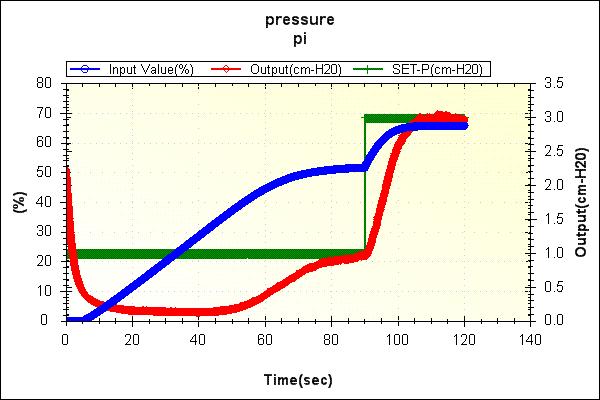
9 Region 8-9% Quarter deay /th deay /th deay ritially damped overdamped 8 Ultimate deay Output m HO /th Deay Δr = m-ho Offset = nput (%) Region -7% / th Deay Experimental Model Experimental RESPONSE K Deay Ratio Offset... OUTPUT/SET PONT.. Model TME
10 Deay Ratio Offset Region 7-8% Model.. / th Deay Experimental.. RESPONSE K Experimental. OUTPUT/SET PONT. Model TME Region K Deay Ratio Offset 8-9% / th Deay Model Experimental Experimental RESPONSE 8. OUTPUT/SET PONT Model TME
11 Greetings, There were things that the ustomer has asked me about your presentation today. -- You showed an experimental response at K = in region in whih you said Offset =. This alls for a "Nope." The offset seems to be zero beause you were using an inorret value for m-bar. believe that offset follows the formula of deltar*(-kk/(+kk)). Chek it out. -- n showing a omparison of Region Ultimate deay showed a frequeny of the experiment that was about. Hz. That's drastially different from your results shown on Slide. ran an experiment and got a little higher frequeny. Also, an't tell that your Output funtion settled down to the initial set point before you hanged the set point. think some mention of and desription of the different frequenies would have been good. believe the ustomer would like to have these things orreted in the next presentation. Look at some notes made on 8 --> Yellow --> Yellow-Team-wk-rev-.pdf JMH
12 Region K Deay Ratio Offset -7% / th Deay Model Experimental.... Experimental RESPONSE. OUTPUT/SET PONT.. Model TME Region K Deay Ratio Offset 7-8% Quarter Deay Model Experimental.... RESPONSE Experimental. OUTPUT/SET PONT.. Model TME
13 K Deay Ratio Offset Region -7% Model -- Ultimate Deay Experimental. -- RESPONSE OUTPUT/SET PONT Experimental Model TME Disturbanes Pressure System PS PS Pressure Sensor Computer PRC 9 Creates Disturbanes PCZ 9 Damper # Damper # Blower PT 9 Pressure Transduer
14 Region Critial Deay Dampers Open Dampers Closed input (%) output (m-ho) time (s) Region / th Deay Dampers Open Dampers Closed nput (%) Output (m-ho) Time (s)
15 Region Quarter Deay Dampers Open Dampers Closed 9. 8 nput (%) 7.. Output (m-h) time (s) Proportional ntegral Design K m( t) = m + K e( t) + e( t) dt τ Charateristi Equation ( τ * τ * t )s (* τ + *K o + ( τ * t C o *K * τ - K + * τ * τ - K K * τ * t )s C *K * t )s + *(K o C o C + *K) = Root Lous K C
16 K=. τ=.7 t =. τ =.8 REAL K C QD = K CU = 8 K C = fu=. K C = K CR = MAGNARY K=. τ=.7 t =. τ =. REAL K C = K C = K CR =9. K CU =8 K C QD =8 fu= MAGNARY
17 K=. τ=.7 t =. τ =. REAL K C QD = K CU = K C =.8 K C =. K CR =. fu= MAGNARY. Region Engineering Critial Deay τ =.8s K =.9% / m H Output (m H)...
18 7 Region Engineering Ultimate Deay τ =.8s K = % / m H Output (m H) Output (m H)..... Region Engineering τ =.8s K C K = % / m H
19 . τ =.s Region Engineering K C K = % / m H Output (m H).... Region Engineering τ =.s K C K =.% / m H Output (m H)... 8
20 Experiment D = (
21 . Engineering Region Critial Deay Output (m H). τ =.s K = 9.% / m H. SettlingTime = 8se τ =.8s. K =.9% / m H SettlingTime = 7se Output (m H)..... τ =.8s K = % / m H Overshoot = 7% SettlingTime = 9se Engineering Region K C τ K =.s = % / m H Overshoot = 8% SettlingTime = se
22 Output (m H)..... τ =.s K = % / m H K C Overshoot = % SettlingTime = se Engineering Region =.s K C = % / m H Overshoot = 8% SettlingTime = se τ K. Region Engineering τ =. s K C K = % / m H Output (m H)...
23 . Region Engineering τ =.s K = % / m H Output (m H)... Engineering Region Output (m H).... τ =.s K = % / m H Overshoot = % SettlingTime = se τ K =.s = % / m H Overshoot = % SettlingTime = se
24 /th Region T =. τ =.s K C K = 8% / m H nput (%) nput (%) /th Region T =. τ =.s K = % / m H
25 nput (%) /th Region T =. τ =.s K = 8% / m H /th Region T = τ =.s K = % / m H Overshoot = % SettlingTime = se nput (%) τ =.s K = 8% / m H Overshoot = % SettlingTime = se τ =.s K = 8% / m H Overshoot = % SettlingTime = se 8 8
26 Output (m H).... Dampers & Open Engineering Disturbane Response 7 Damper Closes Damper Closes Reset Windup
27 Region Conlusions / th Deay K = %/m-h τ =.se. Output (m H).. 8 Region Conlusions K = %/m-h τ =.9se. Output (m H).. 8
28 Region Conlusions K = %/m-h τ =.se 9 8. Output (m H) Appliation of Controller Gain in Experimental Modeling Bath Distillation nformation.... Reflux Ratio 8. Controller Gain = %/ C Reflux Model Atual Reflux Time (minutes)
29 Bath Distillation nformation... Reflux Ratio. Controller Gain = 9 %/ C Reflux Model Atual Reflux.. 8 Time (minutes)
UTC. Engineering 329. Proportional Controller Design. Speed System. John Beverly. Green Team. John Beverly Keith Skiles John Barker.
 UTC Engineering 329 Proportional Controller Design for Speed System By John Beverly Green Team John Beverly Keith Skiles John Barker 24 Mar 2006 Introdution This experiment is intended test the variable
Spray Boot Pressure Station UTC -ENGR 3280-L Week 10 March 20, 2013 Blue Team. Ethan Tummins Jeff Clowdus Jerry Basham
 Spray Boot Pressure Station UTC -ENGR 3280-L Week 10 March 20, 2013 Blue Team Ethan Tummins Jeff Clowdus Jerry Basham Presentation Overview Spray Booth Pressure Station Overview Steady State Operating
Proportional Controller Performance for Aerator Mixer System
 1 Proportional Controller Performance for Aerator Mixer System By Nicholas University of Tennessee at Chattanooga ENGR 329-1 Green Team (Monty Veal, TJ Hurless) April 2th, 21 2 Introduction- The experiment
UTC. Engineering 3280L. Spray Paint Booth Pressure Control System. Caleb Walker. Yellow team: Caroline Brune, Chris Legenski
 UTC Engineering 3280L Spray Paint Booth Pressure Control System Yellow team: Caroline Brune, Chris Legenski Table of Contents I. Introduction... 4 Figure 1: Schematic Diagram of the Dunlap Plant Spray-Paint
Controller Design Based on Transient Response Criteria. Chapter 12 1
 Controller Design Based on Transient Response Criteria Chapter 12 1 Desirable Controller Features 0. Stable 1. Quik responding 2. Adequate disturbane rejetion 3. Insensitive to model, measurement errors
Stabilization of the Precision Positioning Stage Working in the Vacuum Environment by Using the Disturbance Observer
 Proeedings of the 4th IIAE International Conferene on Industrial Appliation Engineering 216 Stabilization of the Preision Positioning Stage Working in the Vauum Environment by Using the Disturbane Observer
University of Tennessee at Chattanooga. Engineering 329. Step Response Characteristics
 University of Tennessee at Chattanooga Engineering 329 Paint Spray Booth Pressure System: Steady-State Operation and Step Response Characteristics Eric L. Young Jonathan Blanco Matthew Chatham-Tombs September
Course roadmap. Step response for 2nd-order system. Step response for 2nd-order system
 ME45: Control Systems Lecture Time response of nd-order systems Prof. Clar Radcliffe and Prof. Jongeun Choi Department of Mechanical Engineering Michigan State University Modeling Laplace transform Transfer
23.1 Tuning controllers, in the large view Quoting from Section 16.7:
 Lesson 23. Tuning a real ontroller - modeling, proess identifiation, fine tuning 23.0 Context We have learned to view proesses as dynami systems, taking are to identify their input, intermediate, and output
Feedback Control of Linear SISO systems. Process Dynamics and Control
 Feedback Control of Linear SISO systems Process Dynamics and Control 1 Open-Loop Process The study of dynamics was limited to open-loop systems Observe process behavior as a result of specific input signals
CHBE320 LECTURE X STABILITY OF CLOSED-LOOP CONTOL SYSTEMS. Professor Dae Ryook Yang
 CHBE320 LECTURE X STABILITY OF CLOSED-LOOP CONTOL SYSTEMS Professor Dae Ryook Yang Spring 208 Dept. of Chemial and Biologial Engineering 0- Road Map of the Leture X Stability of losed-loop ontrol system
Relative Maxima and Minima sections 4.3
 Relative Maxima and Minima setions 4.3 Definition. By a ritial point of a funtion f we mean a point x 0 in the domain at whih either the derivative is zero or it does not exists. So, geometrially, one
Simplify each expression. 1. 6t + 13t 19t 2. 5g + 34g 39g 3. 7k - 15k 8k 4. 2b b 11b n 2-7n 2 3n x 2 - x 2 7x 2
 9-. Plan Objetives To desribe polynomials To add and subtrat polynomials Examples Degree of a Monomial Classifying Polynomials Adding Polynomials Subtrating Polynomials 9- What You ll Learn To desribe
Proportional, Integral & Derivative Control Design. Raktim Bhattacharya
 AERO 422: Active Controls for Aerospace Vehicles Proportional, ntegral & Derivative Control Design Raktim Bhattacharya Laboratory For Uncertainty Quantification Aerospace Engineering, Texas A&M University
AC : A GRAPHICAL USER INTERFACE (GUI) FOR A UNIFIED APPROACH FOR CONTINUOUS-TIME COMPENSATOR DESIGN
 FOR A UNIFIED APPROACH FOR CONTINUOUS-TIME COMPENSATOR DESIGN") AC 28-1986: A GRAPHICAL USER INTERFACE (GUI) FOR A UNIFIED APPROACH FOR CONTINUOUS-TIME COMPENSATOR DESIGN Minh Cao, Wihita State University Minh Cao ompleted his Bahelor s of Siene degree at Wihita State
AC 28-1986: A GRAPHICAL USER INTERFACE (GUI) FOR A UNIFIED APPROACH FOR CONTINUOUS-TIME COMPENSATOR DESIGN Minh Cao, Wihita State University Minh Cao ompleted his Bahelor s of Siene degree at Wihita State
Answers for Homework #6 for CST P
 Answers for Homework #6 for CST 407 02P Assigned 5/10/07, Due 5/17/07 Constructing Evans root locus diagrams in Scilab Root Locus It is easy to construct a root locus of a transfer function in Scilab.
R a) Compare open loop and closed loop control systems. b) Clearly bring out, from basics, Force-current and Force-Voltage analogies.
 Compare open loop and closed loop control systems. b) Clearly bring out, from basics, Force-current and Force-Voltage analogies.") SET - 1 II B. Tech II Semester Supplementary Examinations Dec 01 1. a) Compare open loop and closed loop control systems. b) Clearly bring out, from basics, Force-current and Force-Voltage analogies..
SET - 1 II B. Tech II Semester Supplementary Examinations Dec 01 1. a) Compare open loop and closed loop control systems. b) Clearly bring out, from basics, Force-current and Force-Voltage analogies..
R10 JNTUWORLD B 1 M 1 K 2 M 2. f(t) Figure 1
 Figure 1") Code No: R06 R0 SET - II B. Tech II Semester Regular Examinations April/May 03 CONTROL SYSTEMS (Com. to EEE, ECE, EIE, ECC, AE) Time: 3 hours Max. Marks: 75 Answer any FIVE Questions All Questions carry
Code No: R06 R0 SET - II B. Tech II Semester Regular Examinations April/May 03 CONTROL SYSTEMS (Com. to EEE, ECE, EIE, ECC, AE) Time: 3 hours Max. Marks: 75 Answer any FIVE Questions All Questions carry
Wave Propagation through Random Media
 Chapter 3. Wave Propagation through Random Media 3. Charateristis of Wave Behavior Sound propagation through random media is the entral part of this investigation. This hapter presents a frame of referene
Solutions for Tutorial 10 Stability Analysis
 Solutions for Tutorial 1 Stability Analysis 1.1 In this question, you will analyze the series of three isothermal CSTR s show in Figure 1.1. The model for each reactor is the same at presented in Textbook
Dr Ian R. Manchester Dr Ian R. Manchester AMME 3500 : Review
 Week Date Content Notes 1 6 Mar Introduction 2 13 Mar Frequency Domain Modelling 3 20 Mar Transient Performance and the s-plane 4 27 Mar Block Diagrams Assign 1 Due 5 3 Apr Feedback System Characteristics
Introduction to Process Control
 Introduction to Process Control For more visit :- www.mpgirnari.in By: M. P. Girnari (SSEC, Bhavnagar) For more visit:- www.mpgirnari.in 1 Contents: Introduction Process control Dynamics Stability The
Chapter 7 Control. Part Classical Control. Mobile Robotics - Prof Alonzo Kelly, CMU RI
 Chapter 7 Control 7.1 Classical Control Part 1 1 7.1 Classical Control Outline 7.1.1 Introduction 7.1.2 Virtual Spring Damper 7.1.3 Feedback Control 7.1.4 Model Referenced and Feedforward Control Summary
Lab # 4 Time Response Analysis
 Islamic University of Gaza Faculty of Engineering Computer Engineering Dep. Feedback Control Systems Lab Eng. Tareq Abu Aisha Lab # 4 Lab # 4 Time Response Analysis What is the Time Response? It is an
Control 2. Proportional and Integral control
 Control 2 Proportional and Integral control 1 Disturbance rejection in Proportional Control Θ i =5 + _ Controller K P =20 Motor K=2.45 Θ o Consider first the case where the motor steadystate gain = 2.45
Control for. Maarten Steinbuch Dept. Mechanical Engineering Control Systems Technology Group TU/e
 Control for Maarten Steinbuch Dept. Mechanical Engineering Control Systems Technology Group TU/e Motion Systems m F Introduction Timedomain tuning Frequency domain & stability Filters Feedforward Servo-oriented
Principles and Practice of Automatic Process Control
 Principles and Practice of Automatic Process Control Third Edition Carlos A. Smith, Ph.D., P.E. Department of Chemical Engineering University of South Florida Armando B. Corripio, Ph.D., P.E. Gordon A.
CHAPTER 10: STABILITY &TUNING
 When I complete this chapter, I want to be able to do the following. Determine the stability of a process without control Determine the stability of a closed-loop feedback control system Use these approaches
MEM 355 Performance Enhancement of Dynamical Systems
 MEM 355 Performance Enhancement of Dynamical Systems Frequency Domain Design Intro Harry G. Kwatny Department of Mechanical Engineering & Mechanics Drexel University /5/27 Outline Closed Loop Transfer
SOA/CAS MAY 2003 COURSE 1 EXAM SOLUTIONS
 SOA/CAS MAY 2003 COURSE 1 EXAM SOLUTIONS Prepared by S. Broverman e-mail 2brove@rogers.om website http://members.rogers.om/2brove 1. We identify the following events:. - wathed gymnastis, ) - wathed baseball,
Discussion: Flux correction for cross-contamination. 1. Before measuring: practical considerations for open paths
 Disussion: Flux orretion for ross-ontamination Open Path / Closed Path IRGA omparison 1. Before measuring: pratial onsiderations for open paths 2. Appliation of WPL orretion and omparison with losed path
Blackbody radiation (Text 2.2)
") Blabody radiation (Text.) How Raleigh and Jeans model the problem:. Next step is to alulate how many possible independent standing waves are there per unit frequeny (ν) per unit volume (of avity). It is
Blabody radiation (Text.) How Raleigh and Jeans model the problem:. Next step is to alulate how many possible independent standing waves are there per unit frequeny (ν) per unit volume (of avity). It is
2.010 Fall 2000 Solution of Homework Assignment 7
 . Fall Solution of Homework Assignment 7. Control of Hydraulic Servomechanism. We return to the Hydraulic Servomechanism of Problem in Homework Assignment 6 with additional data which permits quantitative
Improved Extended Kalman Filter for Parameters Identification
 Improved Extended Kalman Filter for Parameters Identifiation Peipei Zhao. Zhenyu Wang. ao Lu. Yulin Lu Institute of Disaster Prevention, Langfang,Hebei Provine, China SUMMARY: he extended Kalman filter
CHBE320 LECTURE XI CONTROLLER DESIGN AND PID CONTOLLER TUNING. Professor Dae Ryook Yang
 CHBE320 LECTURE XI CONTROLLER DESIGN AND PID CONTOLLER TUNING Professor Dae Ryook Yang Spring 2018 Dept. of Chemical and Biological Engineering 11-1 Road Map of the Lecture XI Controller Design and PID
Today we re going to talk about time delays, affectionately referred to as e -st in the Laplace domain. Why e -st? Recall: time.
 6.302 Feedba Systems Reitation 23: ime Delays oday we re going to tal about time delays, affetionately referred to as e -st in the Laplae domain. Why e -st? Reall: time h(t) delay h(t-) Laplae transform:
Process Control and Instrumentation Prof. A. K. Jana Department of Chemical Engineering Indian Institute of Technology, Kharagpur
 Process Control and Instrumentation Prof. A. K. Jana Department of Chemical Engineering Indian Institute of Technology, Kharagpur Lecture - 17 Feedback Control Schemes (Contd.) In the last class we discussed
Control Systems. Control Systems Design Lead-Lag Compensator.
 Design Lead-Lag Compensator hibum@seoulteh.a.kr Outline Lead ompensator design in frequeny domain Lead ompensator design steps. Example on lead ompensator design. Frequeny Domain Design Frequeny response
Analog Circuits Prof. Jayanta Mukherjee Department of Electrical Engineering Indian Institute of Technology - Bombay
 Analog Circuits Prof. Jayanta Mukherjee Department of Electrical Engineering Indian Institute of Technology - Bombay Week 05 Module - 05 Tutorial No.4 Welcome everyone my name is Basudev Majumder, I am
Vibration and Radiation Behavior of Loudspeaker s Membrane
 Hands-On Training 2 Vibration and Radiation Behavior of Loudspeaker s Membrane 1 Objetive of the Hands-on Training - Understanding the need for distributed parameters to model loudspeakers at higher frequenies
ECE-320 Linear Control Systems. Winter 2013, Exam 1. No calculators or computers allowed, you may leave your answers as fractions.
 ECE-320 Linear Control Systems Winter 2013, Exam 1 No alulators or omputers allowed, you may leave your answers as frations. All problems are worth 3 points unless noted otherwise. Total /100 1 Problems
University of Science and Technology, Sudan Department of Chemical Engineering.
 ISO 91:28 Certified Volume 3, Issue 6, November 214 Design and Decoupling of Control System for a Continuous Stirred Tank Reactor (CSTR) Georgeous, N.B *1 and Gasmalseed, G.A, Abdalla, B.K (1-2) University
Lab 5: Harmonic Oscillations and Damping
 Introduction Lab 5: Harmonic Oscillations and Damping In this lab, you will explore the oscillations of a mass-spring system, with and without damping. You'll get to see how changing various parameters
Motor Sizing Application Note
 PAE-TILOGY Linear Motors 70 Mill orest d. Webster, TX 77598 (8) 6-7750 ax (8) 6-7760 www.trilogysystems.om E-mail emn_support_trilogy@parker.om Motor Sizing Appliation Note By Jak Marsh Introdution Linear
EE C128 / ME C134 Fall 2014 HW 6.2 Solutions. HW 6.2 Solutions
 EE C28 / ME C34 Fall 24 HW 6.2 Solutions. PI Controller For the system G = K (s+)(s+3)(s+8) HW 6.2 Solutions in negative feedback operating at a damping ratio of., we are going to design a PI controller
Open Loop Tuning Rules
 Open Loop Tuning Rules Based on approximate process models Process Reaction Curve: The process reaction curve is an approximate model of the process, assuming the process behaves as a first order plus
y = 7x 2 + 2x 7 ( x, f (x)) y = 3x + 6 f (x) = 3( x 3) 2 dy dx = 3 dy dx =14x + 2 dy dy dx = 2x = 6x 18 dx dx = 2ax + b
) y = 3x + 6 f (x) = 3( x 3) 2 dy dx = 3 dy dx =14x + 2 dy dy dx = 2x = 6x 18 dx dx = 2ax + b") Rates of hange III Differentiation Workbook Limits For question, 1., draw up a artesian plane and plot your point [( x + h), f ( x + h) ] ( x, f (x)), and your point and visualise how the limit from first
Rates of hange III Differentiation Workbook Limits For question, 1., draw up a artesian plane and plot your point [( x + h), f ( x + h) ] ( x, f (x)), and your point and visualise how the limit from first
PREDICTION OF THE DENSITIES AND PRESSURES OF ETHANE ON THE COEXISTENCE
 PREDICTION OF THE DENSITIES AND PRESSURES OF ETHANE ON THE COEXISTENCE A. Abbai *, Faulté des Sienes, Département de Chimie, Université Badji-Mokhtar, B. P.12, El-Hadjar, Annaba (23200), Algeria, e-mail
a. Closed-loop system; b. equivalent transfer function Then the CLTF () T is s the poles of () T are s from a contribution of a
 T is s the poles of () T are s from a contribution of a") Root Locus Simple definition Locus of points on the s- plane that represents the poles of a system as one or more parameter vary. RL and its relation to poles of a closed loop system RL and its relation
Root Locus Simple definition Locus of points on the s- plane that represents the poles of a system as one or more parameter vary. RL and its relation to poles of a closed loop system RL and its relation
Critical Reflections on the Hafele and Keating Experiment
 Critial Refletions on the Hafele and Keating Experiment W.Nawrot In 1971 Hafele and Keating performed their famous experiment whih onfirmed the time dilation predited by SRT by use of marosopi loks. As
6.302 Feedback Systems Recitation 16: Compensation Prof. Joel L. Dawson
 Bode Obstacle Course is one technique for doing compensation, or designing a feedback system to make the closed-loop behavior what we want it to be. To review: - G c (s) G(s) H(s) you are here! plant For
Chapter 5 HW Solution
 Chapter 5 HW Solution Review Questions. 1, 6. As usual, I think these are just a matter of text lookup. 1. Name the four components of a block diagram for a linear, time-invariant system. Let s see, I
EE 321 Project Spring 2018
 EE 21 Projet Spring 2018 This ourse projet is intended to be an individual effort projet. The student is required to omplete the work individually, without help from anyone else. (The student may, however,
Understanding Line-Edge Roughness Problems with Metrology. Chris Mack
 Understanding ine-edge Roughness Problems with Metrology Chris Mak www.lithoguru.om Outline Measuring line-edge roughness (ER) Any attempt to understand ER begins with data Soures of bias in ER measurement
Routh-Hurwitz Lecture Routh-Hurwitz Stability test
 ECE 35 Routh-Hurwitz Leture Routh-Hurwitz Staility test AStolp /3/6, //9, /6/ Denominator of transfer funtion or signal: s n s n s n 3 s n 3 a s a Usually of the Closed-loop transfer funtion denominator
Course Outline. Higher Order Poles: Example. Higher Order Poles. Amme 3500 : System Dynamics & Control. State Space Design. 1 G(s) = s(s + 2)(s +10)
 = s(s + 2)(s +10)") Amme 35 : System Dynamics Control State Space Design Course Outline Week Date Content Assignment Notes 1 1 Mar Introduction 2 8 Mar Frequency Domain Modelling 3 15 Mar Transient Performance and the s-plane
Amme 35 : System Dynamics Control State Space Design Course Outline Week Date Content Assignment Notes 1 1 Mar Introduction 2 8 Mar Frequency Domain Modelling 3 15 Mar Transient Performance and the s-plane
6.1 Sketch the z-domain root locus and find the critical gain for the following systems K., the closed-loop characteristic equation is K + z 0.
 6. Sketch the z-domain root locus and find the critical gain for the following systems K (i) Gz () z 4. (ii) Gz K () ( z+ 9. )( z 9. ) (iii) Gz () Kz ( z. )( z ) (iv) Gz () Kz ( + 9. ) ( z. )( z 8. ) (i)
Stress triaxiality to evaluate the effective distance in the volumetric approach in fracture mechanics
 IOSR Journal of ehanial and Civil Engineering (IOSR-JCE) e-issn: 78-1684,p-ISSN: 30-334X, Volume 11, Issue 6 Ver. IV (Nov- De. 014), PP 1-6 Stress triaxiality to evaluate the effetive distane in the volumetri
NAME section. BANNER ID N00 MAT 102 LAST EXAM Fall Complete each problem using the answer key general forms file provided.
 NAME setion BANNER ID N00 MAT 0 LAST EXAM Fall 0 Comlete eah roblem using the answer key general forms file rovided. Chek-list for eah roblem: ) State the Model used: samling distribution of the means,
Duct Acoustics. Chap.4 Duct Acoustics. Plane wave
 Chap.4 Dut Aoustis Dut Aoustis Plane wave A sound propagation in pipes with different ross-setional area f the wavelength of sound is large in omparison with the diameter of the pipe the sound propagates
Problems -X-O («) s-plane. s-plane *~8 -X -5. id) X s-plane. s-plane. -* Xtg) FIGURE P8.1. j-plane. JO) k JO)
 s-plane. s-plane *~8 -X -5. id) X s-plane. s-plane. -* Xtg) FIGURE P8.1. j-plane. JO) k JO)") Problems 1. For each of the root loci shown in Figure P8.1, tell whether or not the sketch can be a root locus. If the sketch cannot be a root locus, explain why. Give all reasons. [Section: 8.4] *~8 -X-O
Problems 1. For each of the root loci shown in Figure P8.1, tell whether or not the sketch can be a root locus. If the sketch cannot be a root locus, explain why. Give all reasons. [Section: 8.4] *~8 -X-O
ECE 320 Linear Control Systems Winter Lab 1 Time Domain Analysis of a 1DOF Rectilinear System
 Amplitude ECE 3 Linear Control Systems Winter - Lab Time Domain Analysis of a DOF Rectilinear System Objective: Become familiar with the ECP control system and MATLAB interface Collect experimental data
Lab 3: Model based Position Control of a Cart
 I. Objective Lab 3: Model based Position Control of a Cart The goal of this lab is to help understand the methodology to design a controller using the given plant dynamics. Specifically, we would do position
Introduction to Machine Learning Prof. Sudeshna Sarkar Department of Computer Science and Engineering Indian Institute of Technology, Kharagpur
 Introduction to Machine Learning Prof. Sudeshna Sarkar Department of Computer Science and Engineering Indian Institute of Technology, Kharagpur Module 2 Lecture 05 Linear Regression Good morning, welcome
f(x)= 2x 2 +x f(x)= x 3 f(x)= x 3 +2
= 2x 2 +x f(x)= x 3 f(x)= x 3 +2") Show that the following functions 1. Warm up Functions even and odd 2. Review Problems From Friday 3. Inverse Functions are even, odd or neither using function notation. f(x)= 2x 2 f(x)= 2x 2 +x f(x)=
Show that the following functions 1. Warm up Functions even and odd 2. Review Problems From Friday 3. Inverse Functions are even, odd or neither using function notation. f(x)= 2x 2 f(x)= 2x 2 +x f(x)=
2.004 Dynamics and Control II Spring 2008
 MIT OpenCourseWare http://ocw.mit.edu 2.004 Dynamics and Control II Spring 2008 For information about citing these materials or our Terms of Use, visit: http://ocw.mit.edu/terms. Massachusetts Institute
Mathematics II. Tutorial 5 Basic mathematical modelling. Groups: B03 & B08. Ngo Quoc Anh Department of Mathematics National University of Singapore
 Mathematis II Tutorial 5 Basi mathematial modelling Groups: B03 & B08 February 29, 2012 Mathematis II Ngo Quo Anh Ngo Quo Anh Department of Mathematis National University of Singapore 1/13 : The ost of
(Refer Slide Time: 00:01:30 min)
") Control Engineering Prof. M. Gopal Department of Electrical Engineering Indian Institute of Technology, Delhi Lecture - 3 Introduction to Control Problem (Contd.) Well friends, I have been giving you various
Control Engineering Prof. M. Gopal Department of Electrical Engineering Indian Institute of Technology, Delhi Lecture - 3 Introduction to Control Problem (Contd.) Well friends, I have been giving you various
The Laws of Acceleration
 The Laws of Aeleration The Relationships between Time, Veloity, and Rate of Aeleration Copyright 2001 Joseph A. Rybzyk Abstrat Presented is a theory in fundamental theoretial physis that establishes the
RESEARCH ON RANDOM FOURIER WAVE-NUMBER SPECTRUM OF FLUCTUATING WIND SPEED
 The Seventh Asia-Paifi Conferene on Wind Engineering, November 8-1, 9, Taipei, Taiwan RESEARCH ON RANDOM FORIER WAVE-NMBER SPECTRM OF FLCTATING WIND SPEED Qi Yan 1, Jie Li 1 Ph D. andidate, Department
Step input, ramp input, parabolic input and impulse input signals. 2. What is the initial slope of a step response of a first order system?
 IC6501 CONTROL SYSTEM UNIT-II TIME RESPONSE PART-A 1. What are the standard test signals employed for time domain studies?(or) List the standard test signals used in analysis of control systems? (April
Control Systems I. Lecture 6: Poles and Zeros. Readings: Emilio Frazzoli. Institute for Dynamic Systems and Control D-MAVT ETH Zürich
 Control Systems I Lecture 6: Poles and Zeros Readings: Emilio Frazzoli Institute for Dynamic Systems and Control D-MAVT ETH Zürich October 27, 2017 E. Frazzoli (ETH) Lecture 6: Control Systems I 27/10/2017
Control Systems. Root Locus & Pole Assignment. L. Lanari
 Control Systems Root Locus & Pole Assignment L. Lanari Outline root-locus definition main rules for hand plotting root locus as a design tool other use of the root locus pole assignment Lanari: CS - Root
Outline. Classical Control. Lecture 5
 Outline Outline Outline 1 What is 2 Outline What is Why use? Sketching a 1 What is Why use? Sketching a 2 Gain Controller Lead Compensation Lag Compensation What is Properties of a General System Why use?
ME 475/591 Control Systems Final Exam Fall '99
 ME 475/591 Control Systems Final Exam Fall '99 Closed book closed notes portion of exam. Answer 5 of the 6 questions below (20 points total) 1) What is a phase margin? Under ideal circumstances, what does
(Refer Slide Time: 2:11)
") Control Engineering Prof. Madan Gopal Department of Electrical Engineering Indian institute of Technology, Delhi Lecture - 40 Feedback System Performance based on the Frequency Response (Contd.) The summary
Control Engineering Prof. Madan Gopal Department of Electrical Engineering Indian institute of Technology, Delhi Lecture - 40 Feedback System Performance based on the Frequency Response (Contd.) The summary
EDEXCEL NATIONAL CERTIFICATE UNIT 28 FURTHER MATHEMATICS FOR TECHNICIANS OUTCOME 3 TUTORIAL 1 - TRIGONOMETRICAL GRAPHS
 EDEXCEL NATIONAL CERTIFICATE UNIT 28 FURTHER MATHEMATICS FOR TECHNICIANS OUTCOME 3 TUTORIAL 1 - TRIGONOMETRICAL GRAPHS CONTENTS 3 Be able to understand how to manipulate trigonometric expressions and apply
(b) A unity feedback system is characterized by the transfer function. Design a suitable compensator to meet the following specifications:
 A unity feedback system is characterized by the transfer function. Design a suitable compensator to meet the following specifications:") 1. (a) The open loop transfer function of a unity feedback control system is given by G(S) = K/S(1+0.1S)(1+S) (i) Determine the value of K so that the resonance peak M r of the system is equal to 1.4.
1. (a) The open loop transfer function of a unity feedback control system is given by G(S) = K/S(1+0.1S)(1+S) (i) Determine the value of K so that the resonance peak M r of the system is equal to 1.4.
Student Exploration: Diffusion
 Name: Date: Student Exploration: Diffusion Vocabulary: absolute zero, controlled experiment, diffusion, dynamic equilibrium, Kelvin scale, kinetic energy Prior Knowledge Question (Do this BEFORE using
MITOCW watch?v=poho4pztw78
 MITOCW watch?v=poho4pztw78 GILBERT STRANG: OK. So this is a video in which we go for second-order equations, constant coefficients. We look for the impulse response, the key function in this whole business,
MATHEMATICS MHT-CET TRIUMPH. Salient Features MULTIPLE CHOICE
 Written in aordane with the latest MHT-CET Paper Pattern whih inludes topis based on Std. XII S. and relevant hapters of Std. XI S. (Maharashtra State Board) MHT-CET TRIUMPH MATHEMATICS MULTIPLE CHOICE
(Refer Slide Time: 1:42)
") Control Engineering Prof. Madan Gopal Department of Electrical Engineering Indian Institute of Technology, Delhi Lecture - 21 Basic Principles of Feedback Control (Contd..) Friends, let me get started
Control Engineering Prof. Madan Gopal Department of Electrical Engineering Indian Institute of Technology, Delhi Lecture - 21 Basic Principles of Feedback Control (Contd..) Friends, let me get started
Index Accumulation, 53 Accuracy: numerical integration, sensor, 383, Adaptive tuning: expert system, 528 gain scheduling, 518, 529, 709,
 Accumulation, 53 Accuracy: numerical integration, 83-84 sensor, 383, 772-773 Adaptive tuning: expert system, 528 gain scheduling, 518, 529, 709, 715 input conversion, 519 reasons for, 512-517 relay auto-tuning,
Energy Concept g. y 1
 nerg Conept Components of the energ euation z is the elevation head is the pressure head-potential head V /g is the dnami head-kineti head H z + + V g V g S f x V g GL HGL S o x x SPCIFIC NRGY CONCPT Speifi
EE 422G - Signals and Systems Laboratory
 EE 4G - Signals and Systems Laboratory Lab 9 PID Control Kevin D. Donohue Department of Electrical and Computer Engineering University of Kentucky Lexington, KY 40506 April, 04 Objectives: Identify the
Control Theory association of mathematics and engineering
 Control Theory assoiation of mathematis and engineering Wojieh Mitkowski Krzysztof Oprzedkiewiz Department of Automatis AGH Univ. of Siene & Tehnology, Craow, Poland, Abstrat In this paper a methodology
IC6501 CONTROL SYSTEMS
 DHANALAKSHMI COLLEGE OF ENGINEERING CHENNAI DEPARTMENT OF ELECTRICAL AND ELECTRONICS ENGINEERING YEAR/SEMESTER: II/IV IC6501 CONTROL SYSTEMS UNIT I SYSTEMS AND THEIR REPRESENTATION 1. What is the mathematical
Analysis and Design of Control Systems in the Time Domain
 Chapter 6 Analysis and Design of Control Systems in the Time Domain 6. Concepts of feedback control Given a system, we can classify it as an open loop or a closed loop depends on the usage of the feedback.
Closed loop control of a flap exposed to harmonic aerodynamic actuation. Clara M. Velte Robert Mikkelsen Jens N. Sørensen Teodor Kaloyanov Mac Gaunaa
 Closed loop ontrol of a flap exposed to harmoni aerodynami atuation Clara M. Velte Robert Mikkelsen Jens N. Sørensen Teodor aloyanov Ma Gaunaa Ative flap ontrol for gust alleviation Objetive: proof-of-onept
ECE382/ME482 Spring 2005 Homework 7 Solution April 17, K(s + 0.2) s 2 (s + 2)(s + 5) G(s) =
 s 2 (s + 2)(s + 5) G(s) =") ECE382/ME482 Spring 25 Homework 7 Solution April 17, 25 1 Solution to HW7 AP9.5 We are given a system with open loop transfer function G(s) = K(s +.2) s 2 (s + 2)(s + 5) (1) and unity negative feedback.
ECE382/ME482 Spring 25 Homework 7 Solution April 17, 25 1 Solution to HW7 AP9.5 We are given a system with open loop transfer function G(s) = K(s +.2) s 2 (s + 2)(s + 5) (1) and unity negative feedback.
Determination of the reaction order
 5/7/07 A quote of the wee (or amel of the wee): Apply yourself. Get all the eduation you an, but then... do something. Don't just stand there, mae it happen. Lee Iaoa Physial Chemistry GTM/5 reation order
CHAPTER 7 FRACTIONAL ORDER SYSTEMS WITH FRACTIONAL ORDER CONTROLLERS
 9 CHAPTER 7 FRACTIONAL ORDER SYSTEMS WITH FRACTIONAL ORDER CONTROLLERS 7. FRACTIONAL ORDER SYSTEMS Fractional derivatives provide an excellent instrument for the description of memory and hereditary properties
MITOCW MIT8_01F16_L12v01_360p
 MITOCW MIT8_01F16_L12v01_360p Let's look at a typical application of Newton's second law for a system of objects. So what I want to consider is a system of pulleys and masses. So I'll have a fixed surface
Dr Ian R. Manchester
 Week Content Notes 1 Introduction 2 Frequency Domain Modelling 3 Transient Performance and the s-plane 4 Block Diagrams 5 Feedback System Characteristics Assign 1 Due 6 Root Locus 7 Root Locus 2 Assign
Outline. Classical Control. Lecture 2
 Outline Outline Outline Review of Material from Lecture 2 New Stuff - Outline Review of Lecture System Performance Effect of Poles Review of Material from Lecture System Performance Effect of Poles 2 New
Ch 14: Feedback Control systems
 Ch 4: Feedback Control systems Part IV A is concerned with sinle loop control The followin topics are covered in chapter 4: The concept of feedback control Block diaram development Classical feedback controllers
Speed-feedback Direct-drive Control of a Low-speed Transverse Flux-type Motor with Large Number of Poles for Ship Propulsion
 Speed-feedbak Diret-drive Control of a Low-speed Transverse Flux-type Motor with Large Number of Poles for Ship Propulsion Y. Yamamoto, T. Nakamura 2, Y. Takada, T. Koseki, Y. Aoyama 3, and Y. Iwaji 3
The gravitational phenomena without the curved spacetime
 The gravitational phenomena without the urved spaetime Mirosław J. Kubiak Abstrat: In this paper was presented a desription of the gravitational phenomena in the new medium, different than the urved spaetime,
Unit Trip April 20, 2011, 13:40:53 CDT. McDonald Angle Relative to U.T. Austin Second
 _35_EE394J_Spring11 Order_Illustrator.doc Ringdown Analysis of Voltage Phase Angle Using 30 Point-per- Synchrophasor Data and the Excel Solver 52.5 57.75.19 52.95 0.95-1.19 53.30 2.28 1.84 0.544 0.127
Poles, Zeros and System Response
 Time Response After the engineer obtains a mathematical representation of a subsystem, the subsystem is analyzed for its transient and steady state responses to see if these characteristics yield the desired