PRELIMINARY DRAFT INDIAN STANDARD METHOD FOR CALIBRATION AND CLASSIFICATION OF TORQUE MEASURING DEVICES INCLUDING TORQUE WRENCH TESTER
|
|
|
- Andra Brooks
- 5 years ago
- Views:
Transcription
1 For BIS Use Only Doc: PGD 34(1203)P PRELIMINARY DRAFT INDIAN STANDARD METHOD FOR CALIBRATION AND CLASSIFICATION OF TORQUE MEASURING DEVICES INCLUDING TORQUE WRENCH TESTER Not to be reproduced without the Permission of BIS or used as Standard Last Date for receipt of Comments is 30 September 2011 FOREWORD This Indian Standard will be considered for adoption by the Bureau of Indian Standards, after the draft finalized by the Hand Tools Sectional Committee, PGD 34 and approved by the Production and General Engineering Division Council (PGDC). This draft has been prepared based on the prevalent practice followed by Indian Industry. While preparing this draft standard considerable assistance has been derived from BS 7882: 2008 Method for calibration and classification of torque measuring devices. For the purpose of deciding whether a particular requirement of this standard is complied with, the final value, observed or calculated, expressing the result of test or analysis, shall be rounded off in accordance with IS 2:1960 Rules for rounding off numerical values (revised). The number of significant places retained in the rounded off value off value should be the same as that of the specified value in this standard.
2 PRELIMINARY DRAFT INDIAN STANDARD METHOD FOR CALIBRATION AND CLASSIFICATION OF TORQUE MEASURING DEVICES, INCLUDING TORQUE WRENCH TESTER 1. Scope This Indian Standard specifies the requirements for the calibration and classification of torque measuring devices, including those used for the calibration of hand torque tools. It describes the method of calibration, calculation of calibration results and the classification of the torque measuring device in a static mode. The information to be given on the certificate of calibration is also listed. 2. Symbols and Abbreviations For the purpose of this Standard, the following abbreviations and symbols shall apply: a 6 d d omax Ei Eit L O a Ro Rl R2 R 3 r T min u 1 u 2 u 3 u 4 u 7 u 8 u c u s w 5 Temperature Uncertainty Deflection Maximum Residual Deflection Relative Error of Indication Relative Error of Interpolation Scale interval Overall Accuracy of the Device Relative Residual Deflection Relative Repeatability Relative Reproducibility Relative Reversibility Resolution Lower Limit of Calibration Calibration Torque Uncertainty Reproducibility Uncertainty Repeatability Uncertainty Resolution Uncertainty Error of Interpolation Uncertainty Reversibility Uncertainty Combined Standard Uncertainty Reversibility Uncertainty Residual Deflection Uncertainty 3. Terms and Definitions For the purpose of this Standard, the following terms and definitions shall apply. 3.1 Calibration Torque Torque with traceability derived from national standards of mass, length and time, and of specified uncertainty of measurement, which can be applied to the torque measuring device
3 3.2 Deflection (d) Algebraic difference between the indicator reading prior to the application of a torque and the indicator reading for each applied torque in a given measurement series. NOTE: The deflection may be derived from either digital data output or visual data output. 3.3 Data Acquisition System Electronic module that has the ability to transfer, store, amplify and filter signals from a torque measuring device. This is applicable for Electronic Torque Measuring device (see Fig. 2). 3.4 Loading Direction Direction of applied torque, either clockwise or anti-clockwise about the axis of rotation, when viewed from the end of the torque measuring device to which the calibration torque is applied. 3.5 Lower Limit of Calibration (T min ) Lower value of torque as given in Table 2 at which a torque measuring device of a given class can be calibrated. 3.6 Reference Standard Equipment used to generate or to measure the reference torque applied to the torque measuring device that is being calibrated 3.7 Relative Error of Indication (Ei ) Mean deflection for a given value of increasing torque minus the corresponding value of applied torque. NOTE: 1 For the purposes of this Indian standard, relative error of indication is expressed as a percentage of applied torque. 2 Relative error of indication is only used where the deflection is in units of torque. 3.8 Relative Error of Interpolation (Eit) Difference between the value of the mean deflection for a given value of increasing torque and the corresponding calculated value of deflection for the given torque, obtained from a mathematically fitted curve. This is applicable in case of deflection is measured in other than torque units. NOTE: For the purposes of this standard, relative error of interpolation is expressed as a percentage of the computed deflection for the given increasing torque. 3.9 Relative Repeatability (Rl) Closeness of the agreement between the results of two successive measurements from the same applied torque, carried out under the same conditions of measurement.
4 3.10 Relative Reproducibility (R2) Closeness of agreement between the results of successive measurements from the same applied torque, carried out under changed conditions of measurement Relative Residual Deflection (Ro) Maximum residual deflection obtained from all the series of torques. NOTE: For the purposes of this standard, relative residual deflection is expressed as a percentage of the mean deflection for the maximum torque applied Relative Reversibility Difference between the deflection obtained from the last given torque series applied in an increasing mode and the deflection obtained from the same given torque applied in a decreasing mode. NOTE: For the purposes of this standard, relative reversibility is expressed as a percentage of the deflection of the last series for the given torque, applied in an increasing mode Residual Deflection Algebraic difference between the indicator readings before and after the application of a single series of torques Resolution Smallest discernable measurement interval on the torque measuring device indicator 3.15 Torque Product of tangential force and length applied about a known centre of rotation 3.16 Torque Measuring Device System comprising an electrical, mechanical, hydraulic or optical torque measuring device with associated instrumentation, including the automated logging of data when part of the device. NOTE: The instrumentation can be an electronic instrument, a mechanical device, i. e. a scale and pointer system, or a Bourdon tube instrument.
5
6 4. Preparation For Calibration 4.1 Reference Standard Uncertainty of calibration torques Values for the maximum permissible uncertainty of the calibration torques applied for the determination of different classifications of the torque measuring device shall not exceed the values given in Table 1. Where a reference standard is used to determine a calibration torque, it shall conform to Table 1. TABLE 1 Uncertainty of Calibration Torques (Clause 4.1.1) Class of Torque Measuring Device to be Calibrated Maximum Permissible Uncertainty of Calibration Torque Applied A (in ) 0.05 ± ± ± ± ± ± ±1.00 Using a coverage factor of k = 2 to give a confidence level of approximately Traceability of measurements All definitive measurements, such as mass, length, time and temperature shall be traceable to national standards; evidence of this shall be provided by a certificate of calibration. 4.2 Condition and Identification of a Torque Measuring Device Calibration shall not be commenced unless the torque measuring device is considered to be in good working order and is identified with a serial number. The maximum working torque shall first have been established. NOTE: If needed the torque measuring device is adjusted or repaired prior to calibration All parts of the torque measuring device shall be identified in accordance with 3.2.1, including the following, where applicable: a) Signal cables b) Switch boxes c) Interfaces d) Data acquisition systems e) Computers f) Software (where information is available) g) Drive mechanism
7 4.2.3 Where an electrical indicator used with a torque measuring device is replaced with another. The following requirements shall be met to ensure that the calibration is not invalidated: a) The original indicator shall have a valid calibration certificate, traceable to national standards, that gives the results of a calibration made in terms of the units to be measured. The indicator shall have been calibrated over a range equal to or greater than the range over which it is used with the torque measuring device. b) The replacement indicator shall have a resolution equal to or better than the indicator it is replacing and shall have a valid calibration certificate, traceable to national standards, that gives the results of a calibration made in terms of the units to be measured. The indicator shall have been calibrated over a range equal to or greater than the range over which it is used with the torque measuring device. c) The date of calibration on the certificate for the original indicator shall not precede that of the certificate for the replacement indicator by more than 12 months. d) The certificates for the two indicators show that the readings of the torque measuring device, as measured by the two indicators, agree with the values given below, over the range of the classification of the torque measuring device: ± of indicated reading for a class 0.05 device; ± of indicated reading for a class 0.1 device; ± 0.10 of indicated reading for a class 0.2 device; ± 0.25 of indicated reading for a class 0.5 device; ± 0.50 of indicated reading for a class 1.0 device; ± 1.00 of indicated reading for a class 2.0 device; ± 2.50 of indicated reading for a class 5.0 device. e) If it is necessary to replace cables, the replacement cables shall be of the same specification as the originals to ensure that the calibration remains valid. 4.3 Resolution of the Indicator An indicator can be a direct reading display or the output of a data acquisition system Mechanical Scale The output of the torque measuring device is measured by pre defined mechanical scale with slider on it, the resolution r shall be determined as per the following: Analogue scale r = 1/2. L When the output of the torque measuring device is measured by an indicator with an analogue scale, i.e. a dial gauge or Bourdon tube instrument, the resolution r shall be determined from the ratios between the width of the pointer and the centre-to-centre distance between two adjacent scale graduation marks (scale interval).
8 NOTE: The ratios should be 1/2, 1/5 or 1/ A spacing of at least 1.25 mm shall be used for the estimation of a tenth of the division on the scale When using an optical recognition system, i.e. video, the video frame rate shall be at least 10 times the display update being recorded A Vernier scale of dimensions appropriate to the analogue scale may be used to allow direct fractional reading of the instrument scale division or as agreed between user and manufacturer Digital scale The resolution shall be considered to be one increment of the last active number of the numerical indicator Variation of readings If the readings fluctuate by more than the value previously calculated for the resolution (with no torque applied to the instrument), the resolution shall be deemed to be equal to half the range of fluctuation Units The resolution shall be converted to units of torque Lower limit of calibration (T min ) To ensure that the classification is consistent with the resolution of the torque indicator, a lower limit of calibration shall be determined. The calibration shall not be performed below this lower limit, given by the equation: where: Tmin = a. r r is the resolution determined in accordance with 3.3, a has the following values: 4000 for a class 0.05 torque measuring device; 2000 for a class 0.1 torque measuring device; for a class 0.2 torque measuring device; 400 for a class 0.5 torque measuring device; 200 for a class 1.0 torque measuring device;; 100 for a class 2.0 torque measuring device; 40 for a class 5.0 torque measuring device; 4.4 Number of Calibration Orientations (see Annex A) For classes 0.05 and 0.1, the torque measuring device shall be calibrated in either three different mounting positions, each rotated 120 about the measurement axis, or in four different mounting positions, each rotated 90 about the measurement axis. For all other classes, the torque measuring device shall be calibrated at a minimum of two different mounting positions at least 90 apart. Where the design or specification of the torque measuring device does not allow it to be rotated, a physical disconnection and reconnection of the reference standard shall be deemed acceptable.
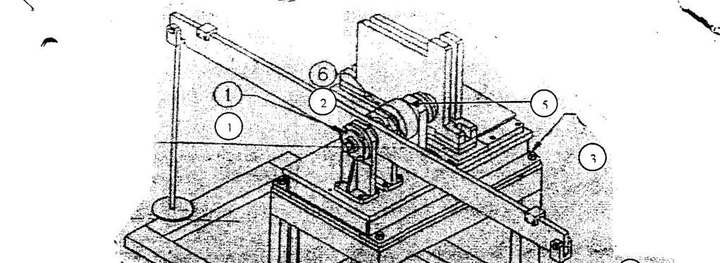
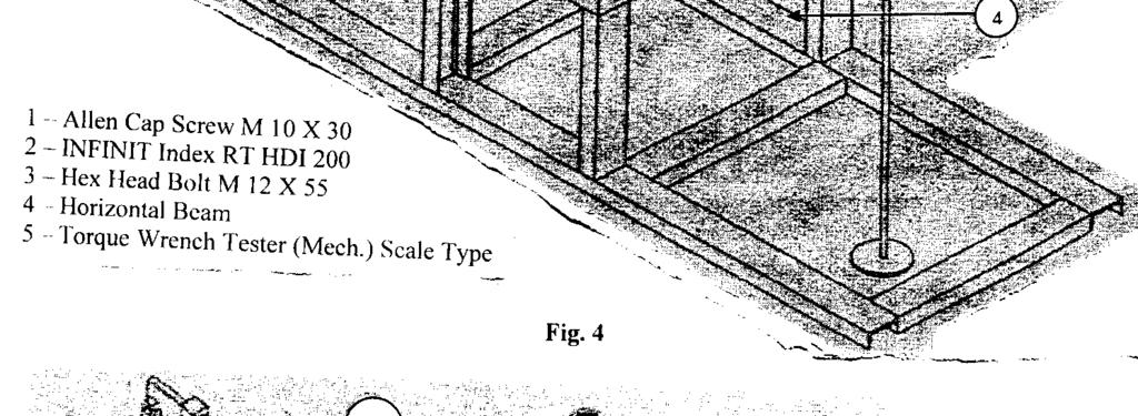
9 4.5 Preliminary Procedure Preliminary procedure (for mechanical torque wrench tester scale type) Place the torque wrench tester (Scale Type) in an appropriate mounting position as shown in Fig. 4. Take every care so that it can be adjusted and aligned about its principal measuring axis between series as shown in the figure. Any misalignment applied to torque measuring device (TWT) during the calibration should be kept as minimum as possible where it is observed that the misalignment applied could have a significant effect on torque measuring device s defilation. This may be considered as a part of uncertainty. The arrangement shown in the Fig. 4 there is remote possibility of this effect on measurement calculations. What ever the deflection observed in the Fig. 4 can be corrected by means of making the beam No. 4 to horizontal position and correct torque can be applied and get desired results and the instrument can be classified accordingly. This is possible due to provided drive and lifting of weights arrangement as shown. Ensure that there is a minimal misalignment between the reference standard and torque measuring device (TWT) Preliminary procedure for measuring electronic torque transducer Place the Electronic Torque Transducer in an appropriate mounting position as shown in Fig. 5. Take every care so that it can be aligned properly about its principal measuring axis between series. Any bending applied to the torque measuring device / Transducer during the calibration should be as minimum as possible. Where it is felt that the bending applied could have a significant effect on the torque measuring device s a deflection. This should be considered as a part of uncertainty. In the arrangement shown in the Fig. 5 there is less possibility of this effect on measurements / calibration. What ever the deflection observed in the arrangement can be corrected by means of making the beam No. 9 to the horizontal position and correct torque can be applied and get desired results and measuring device can be classified accordingly. This is possible due to gear box provided at the back of the arrangement and also lifting of beam mechanism. Ensure that there is a minimum misalignment between the reference standard and torque measuring device / Torque transducer. In the same way hydraulic torque measuring devices can be calibrated by making mounting arrangement. Procedure may be same for calibration.

10
11 4.6.3 Temperature considerations Where the torque measuring device is electrical, connect the torque measuring device, indicator, switchboxes, interfaces, etc., using the associated electrical cables. Switch on and allow to warm-up for the period stated in the manufacturer's handbook. In the absence of any recommendation energize the system for at least 15 min Position a thermometer close to the calibration beam or reference torque measuring device and the torque measuring device to be calibrated. Allow the torque measuring device and all relevant parts of the calibration equipment to attain a stable temperature. record the temperature at the beginning and end of each measurement series Calibrate the torque measuring device at a temperature in the range of 18 C to 28 C. The temperature shall not vary by more than ± 1 C throughout a measurement series Indicator set-up Carry out checks and settings of the indicator in accordance with the manufacturer's handbook. Select the unit of measurement, e.g. N. m, divisions Where a voltage measuring device is to be used as the indicator, carry out checks and settings in accordance with the manufacturer's handbook. Select the appropriate measuring range, e.g. V, mv or µv Preloading procedure Before any calibration or recalibration, preload the torque measuring device and associated connecting components in the appropriate loading direction (i.e. clockwise or anti-clockwise direction) a minimum of three times in succession to the maximum applied torque of the device. Maintain each preload for a period of between 1 min and 1.5 min. The interval between successive application and removal of preloads shall be as uniform as possible. Where the torque measuring device is to be calibrated in both clockwise and anti-clockwise loading directions, preload the torque measuring device for a minimum of three times before the commencement of calibration. 5. Calibration Procedure 5.1 Selection of Calibration Torques Select a series of at least five approximately equally spaced, increasing values of torque from 20 to 100 of maximum applied torque If the calibration is required to be made below 20 then torque steps of 10, 5 and 2 of maximum applied torque may additionally be used, provided that they are greater than the calculated lower limit of the calibration range Where the use of a torque measuring device requires that both increasing and decreasing values of torques are measured, select a single series of decreasing values in accordance with for application at the end of the last series of increasing torques.
12 5.1.4 An increasing torque shall always be applied in a direction from a lower value of torque. A decreasing torque shall always be applied in a direction from a higher value of torque. NOTE: Where a reference torque measuring device has been calibrated with both increasing and decreasing values of torques, it may be used to determine torques in both of these modes. 5.2 Application of Calibration Torques Calibrate in one of the following: a) Clockwise or anti-clockwise direction (see 5.2.2); or b) In both clockwise and anti-clockwise directions (see 5.2.8) After the preloading procedure (see 4.6.4), apply two series of increasing torques in a clockwise or anti-clockwise direction, as required, to the torque measuring device without change of the mounting position. The indicator reading may be tare to zero at the beginning of each measurement series Record the readings of the indicator with zero torque applied to the torque measuring device before and after each application of a series of torques The interval between successive application and removal of torques shall be as uniform as possible. Record the reading of the indicator no less than 30 s after each application or removal of a torque. For the determination of relative residual deflection, record the residual deflection reading no less than 30 s after the torque is completely removed Disturb and remount the torque measuring device in accordance with 3.5. After reconnection, preload the torque measuring device once to maximum applied torque then apply a further series of increasing torques Repeat until torques has been applied at all required orientations Where relative reversibility is required, a single series of decreasing values shall be applied at the end of the last series of increasing torques Where the torque measuring device is required to be calibrated for both clockwise and anti-clockwise torques, repeat the procedure given in to for the opposite direction. 6. Calculation of Results 6.1 Determination of Deflection (Cd) Algebraically subtract the indicator reading for the initial zero torque from the indicated reading for each applied torque and the final zero torque in the measurement series. NOTE: The unit of indicator reading is in units of torque, e.g. N m, or, where a voltage measuring device is used, in units of vous, e.g. V, mv or j1v.
13 6.2 Determination of Relative Repeatability (Rl) For each value of increasing torque applied in a clockwise or anti-clockwise direction, calculate the repeatability of the deflection for the first and second series of applied torque Express the repeatability as a percentage of the mean deflection drl for the first and second applications of the given torque, using equations (1) and (2). where: drl = (d1 +d2)/ 2 - (1) drl is the mean deflection for a given torque; d1 and d2 are the deflections for a given increasing torque (series 1 and 2). (d 1 -d 2 ) 100 R 1 = d R1 - (2) For each value of increasing torque applied in a clockwise or anti-clockwise direction, calculate the reproducibility of the deflection for the series of applied torque The reproducibility shall be expressed as a percentage of the mean deflection dr2 for the applications of the given torque, using equations (3), (4) or (5), as applicable, and (6). where: a) For two orientations: dr2= (d1+d3)/2 - (3) b) For three orientations: dr2= (d l + d 3 + d 4 )/3 - (4) c) For four orientations: dr2= (d l + d 3 + d 4 + d 5 )/ 4 - (5) dr2 is the mean deflection calculated from the first series at each orientation; d l, d 3, d 4 and d 5 are the deflections for a given increasing torque from the first series at each orientation R2 = [(d max d min )/ dr2] (6) where: d max is the maximum deflection for a given increasing torque from all series; d min is the minimum deflection for a given increasing torque from all series.
14 6.4 Determination of Relative Error of Interpolation (Eit) The error of interpolation shall only be determined where the deflection is expressed in units other than those of torque (e.g. in units of V, mv) Compute a "best fit" first, second or third order polynomial equation relating the mean deflection to the increasing calibration torques. Equal weighting shall be given to all points. Compute the polynomial series such that the sum of the squares of the residuals, i.e. the departure of the actual calibration readings from the computed values given by the equation, is a minimum At each increasing calibration torque, calculate the residual as a percentage of the computed deflection for the given torque, using following equation: where: Eit = [(dr 2 -dcomp)/dcomp]. 100 dcomp is the computed deflection for the given increasing torque. 6.5 Determination of Relative Residual Deflection (Ro) Determine the maximum residual deflection obtained from the applied series of torques and express this as a percentage of the mean deflection at maximum applied torque using following equation: where: Ro = (domax / dr2max). 100 dr2 max is the mean deflection at maximum applied torque. 6.6 Determination of Relative Reversibility (R 3 ) Express the relative reversibility as a percentage of the deflection for the given torque from the last applied series of torques, using following equation: where: R3 = [(ddec - dinc)/ dinc] X 100 dinc is the deflection for the application of the last series of a given increasing torque; ddec is the deflection for the application of the corresponding decreasing torque. 6.7 Determination of Relative Error of Indication The relative error of indication shall only be determined where the deflection is expressed in units of torque Calculate for each value of increasing torque applied in a clockwise or anti-clockwise direction the error of indication for the given torque. Calculate the mean deflection (dr2) for the applications of the given torque and express the relative error of indication as a percentage of the true value of torque (Ta), e.g. the accepted value of the applied calibration torque, using following equation:
15 Ei = [(d R2 - Ta)/ Ta]. 100 where: d R2 is the mean deflection calculated from the first series at each orientation; Ta is a given increasing calibration torque. 7 Classification of torque measuring devices 7.1 Procedures for Classification General Where the deflection is expressed in units of torque, and increasing torques have been applied, the classification and range of that classification shall be determined for the following parameters: a) Repeatability; b) Reproducibility; c) Residual deflection; and d) Error of indication. Where decreasing torques has also been applied, the classification and its range for the relative reversibility shall also be determined in addition to these parameters. If deflection is expressed in units of other than those of torque determine the error of interpolation instead of error of indication Uncertainties of measurement are not used to determine the classification Determination of a classification and its range To permit an analysis of the results of the calibration, a target classification shall be selected consistent with the intended use of the torque measuring device At each calibration torque from the maximum applied torque to be calibrated downwards, the values of error calculated for each parameter being classified shall not exceed the value given for the selected classifications in the appropriate column of Table 2. The classification shall cease to apply at the first calibration torque where the limit for the selected classification is exceeded. The minimum range of measurement for a selected classification shall be 20 to 100 of maximum applied torque If conformity with in respect of all of the parameters for which the classification is being sought is achieved, the selected classification shall be deemed to have been met. If the range of one or more of the parameters does not meet the requirements of , then the analysis shall be repeated to determine conformance to a lower classification. NOTES: a) Where calibration torques have been applied below 20 of maximum applied torque and all of the results meet the requirements of then the range of classification of the selected classification can be extended. b) A second classification of lower class and of an extended range can be awarded, provided that all of the requirements of are met in respect of the lower class. For example:
16 class 1.0: from 100 Nom down to 20 N.m; class 2.0: from 100 Nom down to 5 N.m 8. Calibration Certificate 8.1 General TABLE 2 Criteria for Classification of Torque Measuring Devices (Clause ) Class Permissible values Rl R2 Eit Ro R3 Ei 0.05 ±0.025 ±0.05 ±0.025 ±0.0l ±0.062 ± ±0.05 ±0.l0 ±0.05 ±0.02 ±0.125 ± ±0.l0 ±0.20 ±0.l0 ±0.04 ±0.250 ±0.l0 0.5 ±0.25 ±0.50 ±0.25 ±0.l0 ±0.625 ± ±0.50 ±1.00 ±0.50 ±0.20 ±1.250 ± ±1.00 ±2.00 ±1.00 ±0.40 ±2.500 ± ±2.50 ±5.00 ±2.50 ±1.00 ±6.250 ±2.50 When the torque measuring device has satisfied the requirements specified in 3 to 6, a certificate shall be issued stating at least the following: a) The date of the issue of this certificate, which shall also be identified by a unique reference. b) The date of calibration. c) The serial numbers of the torque measuring device and, where appropriate, any mechanical fittings and electrical cables. d) A brief description of the calibration method and the type of calibration equipment used, including the uncertainty of measurement of the applied calibration torque. e) A reference to this standard as a basis of test, f) The range and loading mode of torques over which the torque measuring device conforms to specified in 3 to 6, for a given classification. g) Where the unit of deflection is expressed in units of torque it shall be stated that the device conforms to the parameters of repeatability, reproducibility, relative residual deflection and error of indicator reading. Where reversibility has been determined and classified, this shall also be stated. h) Where the unit of deflection is expressed in units of other than those of torque it shall be stated that the device conforms to the parameters of repeatability, reproducibility, relative residual deflection and error of interpolation. The degree of the equation determined and the coefficients obtained shall also be stated. Where reversibility has been determined and classified, this shall also be stated. i) The uncertainty of measurement for the given calibration values (see Annex B). j) The average temperature and its range of variation or the maximum and minimum temperature recorded of the torque measuring device during the calibration. k) A table of the applied torques and corresponding deflections. Where the calibration laboratory supplies the indicating devices, the uncertainty of measurement of the conditioning devices (including the display, energizing device and cables) can also be included in the calibration certificate.
17 8.2 Frequency of Calibration The torque measuring device shall be recalibrated at least every 12 months and whenever it suffers any damage or has been subject to any repair.
18 Annex A (CLAUSE 4.5) A- 1 Orientation diagrams The following diagrams show examples for the calibration of torque measuring devices. Fig. 6: Example of preloading and calibration sequences for a torque measuring device with round shaft drives, six increasing and decreasing torques, classes 0.05 to 5.0 Fig. 7: Example of preloading and calibration sequences for a torque measuring device with round shaft drives, six increasing torques only, classes 0.05 to 5.0 Fig. 8: Example of preloading and calibration sequences for a torque measuring device with square drives, six increasing and decreasing torques, classes 0.05 to 5.0
19 Fig. 9: Example of preloading and calibration sequences for a torque measuring device with square drives, six increasing torques only, classes 0.05 to 5.0 Fig. 10: Example of preloading and calibration sequences for a torque measuring device, six increasing and decreasing torques, classes 0.2 to 5.0 Fig. 11: Example of preloading and calibration sequences for a torque measuring device, six increasing torques only, classes 0.2 to 5.0
20 Annex B (Clause 8.1) B-1 Method example of determining uncertainty of the calibration results of the torque measuring device B Uncertainty of the calibration results B General For torque measuring devices where the deflection is in torque units, the calibration uncertainty is that of the torque value given by the error of indication when the deflection of the device is a specific torque value. For devices where the deflection is in other units, the calibration uncertainty is that of the torque value calculated from the interpolation equation, at any measured deflection. At each calibration torque T, a combined standard uncertainty u c is calculated from the readings obtained during the calibration. These uncertainties are then multiplied by the coverage factor k = 2 to give an expanded uncertainty value U. n u c = u 2 i and U= k. u c i=1 where: All units are expressed as relative values H! is the standard uncertainty associated with the calibration torque; u 2 is the standard uncertainty associated with the reproducibility of the device; u s is the standard uncertainty associated with the repeatability of the device; u 4 is the standard uncertainty associated with the resolution of indicator; u 6 is the standard uncertainty associated with the residual deflection of the device; u$ is the standard uncertainty associated with the temperature of the device; u 7 is the standard uncertainty associated with the error of interpolation when units other than those of torque are used (see 5.4); u 8 is the standard uncertainty associated with the reversibility of the device; n is the number of uncertainty contributions u t B Calculation of calibration torque uncertainty (u l ) u l \s the standard uncertainty associated with the torques generated by the calibration machine. This value should be obtained from the calibration certificate of the calibration machine. B- 1.3 Calculation of reproducibility uncertainty, u 2 Reproducibility uncertainty is the standard deviation associated with the population of incremental deflections obtained during the calibration. B-1.4 Calculation of repeatability uncertainty (u 3 ) u 2 = 0.5 R 2 / 2 UQ is the uncertainty contribution due to the repeatability of the measured deflection. It can be assumed that, at each calibration torque T: u 3 = 0.5 R 1 / 3
21 B- 1.5 Calculation of resolution uncertainty (u 4 ) Each deflection value is calculated from two readings (the reading with an applied torque minus the reading at zero torque). Because of this, the resolution of the indicator needs to be included twice as a single triangular distribution with a standard uncertainty of ra/6, where r is the resolution expressed as a relative value. Where it is possible to tare the initial reading of each series to zero, a single rectangular distribution with a standard uncertainty of r/jl2 can be used. u 4 = r/ 6 B-1.6 Calculation of residual deflection uncertainty (w 5 ) u 5 is the uncertainty component due to the variation in the relative residual deflection jr 0. B-1.7 Calculation of temperature uncertainty (a 6 ) u 5 = 0.5 R 0 / 3 u Q is the contribution due to the variation of temperature throughout the calibration, together with the uncertainty in the measurement of the calibration temperature. The sensitivity of the device to temperature can be determined using equation: where: u 6 =K Δt /2 3 jfit is the device's relative temperature coefficient expressed as a percentage of maximum applied torque per degree Celsius, derived either by tests or from the manufacturer's specifications. At is the calibration temperature range, allowing for the uncertainty in the measurement of the temperature. NOTE: The temperature coefficient to be used is that of sensitivity, not of zero. B.1.8 Calculation of error of interpolation uncertainty (u 7 ) u 7 is the uncertainty contribution due to the relative error of interpolation. u 7 = 0.5 E it / 6 B.1.9 Calculation of reversibility uncertainty (u s ) u s is the uncertainty component due to the relative reversibility # 3. u 8 = 0.5 R 3 / 3 B-1.10 Calculation of combined standard uncertainty (u c ) For each calibration torque, calculate the combined standard (#) uncertainty u c by combining the individual standard uncertainties in quadrature.
22 B-1.11 Calculation of expanded uncertainty (U) n u c = u 2 i i=1 and U= k. u c where fc = 2. B- 2 Overall accuracy of the device (O a ) The overall accuracy O a of the device can be obtained by combining the classification accuracy with the expanded uncertainty in quadrature. O a =[ (E i / 3) 2 + (U/2) 2 ] 1/2 The overall accuracy of the device is then multiplied by the coverage factor k = 2 to give an expanded uncertainty value U Oa. The classification accuracy is obtained from the error of indication E i column in Table 2. B- 3 Worked examples of calculation of uncertainty of the calibration results of the torque measuring device calibrated in torque units (increasing torques only) B- 3.1 Obtain raw data. B- 3.2 Calculate parameters: mean indicated output, relative repeatability, relative reproducibility, relative error of indication and relative residual deflection. B- 3.3 Classify device using Table 2. B- 3.4 Calculate uncertainties. B Obtain applied torque uncertainty ( u lf '*) B Calculate reproducibility (u 2 ) B Calculate repeatability (u s ) B Calculate resolution (u 4 ) B Calculate residual zero deflection, u$. B Calculate temperature (u 6 ). B Calculate the combined uncertainty (u c ). B Calculate the expanded uncertainty (U).
23 Table 3 Worked example in torque units: 100 N*m torque measuring device clockwise torque, increasing series only Applied torque N-m Raw data After Resetting Mean indicated deflection Applied torque N-m Relative repeatability R l Relative reproducibility R 2 Relative error of indication E i Relative residual deflection R Q Applied torque N-m Classification Relative Relative Error of Relative residual repeatability R l reproducibility * 2 indication E, deflection *o Lower limit of calibration
24 Applied torque N-m Applied torque u 1 Taken from the calibration certificate of the calibration machine. Value Uncert ainty Reproducibility «2 Table 4 Calculation of Uncertainties in accordance with B- 3 (Clause B- 3) Uncertainty contribution Repeatability u 3 Resolution u 4 Residual deflection u s Temperature u 6 Combined uncertainty u 2 = 0.5 R 2 / 2 u 3 = 0.5 R 1 / 3 u 4 = r/ 6 u 5 = 0.5 R 0 / 3 u 6 =K Δt/2 3 n 2 u c = u i Value Uncertai nty Value Uncertai nty Value Uncertai nty Value Uncert ainty Value Uncertai nty i=1 Expanded uncertainty k = 2 U= k. u c
25 B-4 Worked examples of calculation of uncertainty of the calibration results of the torque measuring device calibrated in units other than torque (increasing and decreasing torques) B-4.1 Obtain raw data. B-4.2 Calculate parameters: mean indicated output, relative repeatability, relative reproducibility, relative error of interpolation, relative residual deflection and relative error of reversibility. B-4.3 Classify device using Table 2. B-4.4 Calculate uncertainties. B Obtain applied torque uncertainty (u^) B Calculate reproducibility (u 2 ) B Calculate repeatability (U B ) B Calculate resolution (u 4 ) B Calculate residual zero deflection (u 5 ). B Calculate temperature (U Q ) B Calculate error of interpolation (u 7 ) B Calculate error of reversibility (u & ) B Calculate the combined uncertainty (u c ) B Calculate the expanded uncertainty (U).
26
27 Table 5 Worked example in mv/v: 2 kn* in torque measuring device clockwise torque, increasing and decreasing series Applied torque N«m Raw data Mean indicated deflection Coefficients Fbr a deflection d (mv/v) the applied torque T (N-m) is calculated thus: T = a { d + a 2 d 2 + a 3 d 3 tti = E+3 a 2 = E-l a 3 = -7.E-3 Fbr a given applied torque T (N-m) the expected deflection d (mv/v) is calculated thus: d = b l T + b 2 T 2 + b 3 T* b l = E =3.827E = 1.44E-15
28 Table 5 Worked example in mv/v: 2 kn*m torque measuring device clockwise torque, increasing and decreasing series (continued) Applied torque N-m Relative repeatability R 1 Relative reproducibility JR 2 Relative error of interpolation E it Relative residual deflection J2 0 Relative reversibility JB : * Applied torque N- m Relative repeatability Relative reproducibility Relative error of interpolation it Classification Relative residual deflection *o Relative reversibility *3 Lower limit of calibration ^
29 Appli ed torque N-m Applied torque u t Taken from the calibration certificate of the calibration machine. Value Uncertai nty Table 6 Uncertainties calculated in accordance with B- 4 (Clause B-4) Uncertainty contribution Reproducibility u 2 Repeatability u 3 Resolution u 4 Residual deflection u s Temperature i* 6 Interpolation u 7 u 2 = 0.5 R 2 / 2 u 3 = 0.5 R 1 / 3 u 4 = r/ 6 u 5 = 0.5 R 0 / 3 u 6 =K Δt/2 3 u 7 = 0.5 E it / 6 Value Uncertain ty Value Uncertaint y Value Uncertai nty Value Uncertai nty Value Uncertai nty Value Uncertaint y
30 Table 7 Applied torque (N-m) Reversibility Combined uncertainty Expanded uncertainty k = 2 u 8 = 0.5 R 3 / 3 n 2 u c = u i i=1 U= k. u c Value Uncertainty
31
Guidelines on the Calibration of Static Torque Measuring Devices
 European Association of National Metrology Institutes Guidelines on the Calibration of Static Torque Measuring Devices EURAMET/cg-14/v.01 Previously EA-10/14 July 2007 Calibration Guide EURAMET/cg-14/v.01
EA-10/14. EA Guidelines on the Calibration of Static Torque Measuring Devices. Publication Reference PURPOSE
 Publication Reference EA-10/14 EA Guidelines on the Calibration of Static Torque Measuring Devices PURPOSE This document has been produced by EA to improve harmonisation in determining the calibration
After publication, this Indian Standard will supersede the following Indian Standards:
 For Comments Only Doc: PGD 26(1110)W Draft Indian Standard SPECIFICATION FOR NON-AUTOMATIC WEIGHING INSTRUMENTS PART 1 TERMINOLOGY AND DEFINITIONS ICS No. 01.040.17; 17.100 Not to be reproduced without
ISO 376 Calibration Uncertainty C. Ferrero
 ISO 376 Calibration Uncertainty C. Ferrero For instruments classified for interpolation, the calibration uncertainty is the uncertainty associated with using the interpolation equation to calculate a single
Morehouse. Edward Lane, Morehouse Instrument Company 1742 Sixth Ave York, PA PH: web: sales:
 Morehouse 1 Morehouse Edward Lane, Morehouse Instrument Company 1742 Sixth Ave York, PA 17403 PH: 717-843-0081 web: www.mhforce.com sales: edlane@mhforce.com 2 This presentation will cover the calibration
An Introduction to the Differences Between the Two Most Recognized Force Standards
 An Introduction to the Differences Between the Two Most Recognized Force Standards Morehouse Instrument Company Introduction Morehouse has been performing both ASTM E74 and ISO 376 calibrations for more
ISO INTERNATIONAL STANDARD
 INTERNATIONAL STANDARD ISO 7500-1 Third edition 2004-08-15 Metallic materials Verification of static uniaxial testing machines Part 1: Tension/compression testing machines Verification and calibration
Wheatstone Bridge Nonlinearity
 Index: Nonlinearity Wheatstone Bridge Nonlinearity Introduction General Considerations The "Unbalanced" Circuit The Unbalanced Circuit Table of Contents Output & Nonlinearity with Various Bridge/Strain
GUIDELINE FOR HAND HELD SHEAR VANE TEST
 GUIDELINE FOR HAND HELD SHEAR VANE TEST NZ GEOTECHNICAL SOCIETY INC August 2001 CONTENTS Page 1.0 Introduction 2 2.0 Background 2 3.0 Recommended Practice 3 4.0 Undrained Shear Strength 3 5.0 Particular
Specific Accreditation Guidance. Infrastructure and Asset Integrity. Measurement Uncertainty in Geotechnical Testing
 Specific Accreditation Guidance Infrastructure and Asset Integrity Measurement Uncertainty in Geotechnical Testing January 2018 Copyright National Association of Testing Authorities, Australia 2018 This
Load Cell Approval Field and Laboratory Evaluation Manual
 Load Cell Approval Field and Laboratory Evaluation Category: MASS Revision: c Page: 1 of 9 In 2011 Measurement Canada began phasing in requirements for using approved load cells in selected Heavy Capacity
SVENSK STANDARD SS-EN ISO
 SVENSK STANDARD SS-EN ISO 376:2005 Fastställd 2005-02-04 Utgåva 2 Metalliska material Kalibrering av kraftmätdon avsedda för kontroll av maskiner för enaxlig provning (ISO 376:2004) Metallic materials
SVENSK STANDARD SS-EN ISO 376. Metalliska material Kalibrering av kraftmätdon avsedda för kontroll av maskiner för enaxlig provning (ISO 376:1999)
") SVENSK STANDARD SS-EN ISO 376 Fastställd 2002-02-01 Utgåva 1 Metalliska material Kalibrering av kraftmätdon avsedda för kontroll av maskiner för enaxlig provning (ISO 376:1999) Metallic materials Calibration
SVENSK STANDARD SS-EN ISO 376 Fastställd 2002-02-01 Utgåva 1 Metalliska material Kalibrering av kraftmätdon avsedda för kontroll av maskiner för enaxlig provning (ISO 376:1999) Metallic materials Calibration
Non-destructive testing of steel forgings- Part 1: Magnetic particle inspection (BS EN :1999)
") Non-destructive testing of steel forgings- Part 1: Magnetic particle inspection (BS EN 10228-1:1999) 1 Scope This part of EN 10228 describes the method and acceptance criteria to be used for the magnetic
Non-destructive testing of steel forgings- Part 1: Magnetic particle inspection (BS EN 10228-1:1999) 1 Scope This part of EN 10228 describes the method and acceptance criteria to be used for the magnetic
Calibration Traceability Guidelines
 Calibration Traceability Guidelines Check the website of accrediting bodies for the accredited laboratories individual scope of accreditation www.a2la.org ts.nist.gov/standards/accreditation/index.cfm
ISO INTERNATIONAL STANDARD. Metallic materials Vickers hardness test Part 3: Calibration of reference blocks
 INTERNATIONAL STANDARD ISO 6507-3 Third edition 2005-12-15 Metallic materials Vickers hardness test Part 3: Calibration of reference blocks Matériaux métalliques Essai de dureté Vickers Partie 3: Étalonnage
EA-10/13. EA Guidelines on the Calibration of Temperature Block Calibrators. Publication Reference PURPOSE
 Publication Reference EA-10/13 EA Guidelines on the Calibration of Temperature Block Calibrators PURPOSE This document been produced by EA to improve the harmonisation in the calibration of temperature
Calibration of Temperature Block Calibrators
 European Association of National Metrology Institutes Calibration of Temperature Block Calibrators EURAMET cg-13 Version 2.0 (03/2011) Previously EA-10/13 Calibration Guide EURAMET cg-13 Version 2.0 (03/2011)
SPECIFIC CRITERIA for CALIBRATION LABORATORIES IN MECHANICAL DISCIPLINE : Torque Measuring Devices
 NABL 122-10 NATIONAL ACCREDITATION BOARD FOR TESTING AND CALIBRATION LABORATORIES SPECIFIC CRITERIA for CALIBRATION LABORATORIES IN MECHANICAL DISCIPLINE : Torque Measuring Devices Reviewed by MASTER COPY
Metallic materials Brinell hardness test. Part 3: Calibration of reference blocks
 INTERNATIONAL STANDARD ISO 6506-3 Third edition 2014-10-01 Metallic materials Brinell hardness test Part 3: Calibration of reference blocks Matériaux métalliques Essai de dureté Brinell Partie 3: Étalonnage
Document No: TR 12 Issue No: 1
 ESTIMATION OF THE UNCERTAINTY OF MEASUREMENT BY CALIBRATION LABORATORIES AND SPECIFICATION OF CALIBRATION AND MEASUREMENT CAPABILITY ON SCHEDULES OF ACCREDITATION Prepared by: SADCAS Technical Manage Approved
POWER QUALITY MEASUREMENT PROCEDURE. Version 4 October Power-Quality-Oct-2009-Version-4.doc Page 1 / 12
 POWER QUALITY MEASUREMENT PROCEDURE Version 4 October 2009 Power-Quality-Oct-2009-Version-4.doc Page 1 / 12 MEASNET 2009 Copyright all rights reserved This publication may not be reproduced or utilized
UNCERTAINTY IN TORQUE CALIBRATION USING VERTICAL TORQUE AXIS ARRANGEMENT AND SYMMETRICAL TWO FORCE MEASUREMENT
 UNCERTAINTY IN TORQUE CALIBRATION USING VERTICAL TORQUE AXIS ARRANGEMENT AND SYMMETRICAL TWO FORCE MEASUREMENT Dieter Kenzler 1, Jörg Oblasser 2, Andreas Subaric-Leitis 2 and Christian Ullner 2 1 ) SCHATZ
INTERNATIONAL STANDARD
 INTERNATIONAL STANDARD ISO 8426 Second edition 2008-02-01 Hydraulic fluid power Positive displacement pumps and motors Determination of derived capacity Transmissions hydrauliques Pompes et moteurs volumétriques
Determination of particle size distribution Single particle light interaction methods. Part 4:
 Provläsningsexemplar / Preview INTERNATIONAL STANDARD ISO 21501-4 Second edition 2018-05 Determination of particle size distribution Single particle light interaction methods Part 4: Light scattering airborne
R SANAS Page 1 of 7
 ESTIMATION OF THE UNCERTAINTY OF MEASUREMENT BY CALIBRATION LABORATORIES AND SPECIFICATION OF CALIBRATION AND MEASUREMENT CAPABILITY ON SCHEDULES OF ACCREDITATION Approved By: Chief Executive Officer:
Review of Anemometer Calibration Standards
 Review of Anemometer Calibration Standards Rachael V. Coquilla rvcoquilla@otechwind.com Otech Engineering, Inc., Davis, CA Anemometer calibration defines a relationship between the measured signals from
Guidelines on the Calibration of Automatic Instruments for Weighing Road Vehicles in Motion and Measuring Axle Loads AWICal WIM Guide May 2018
 Guidelines on the Calibration of Automatic Instruments for Weighing Road Vehicles in Motion and Measuring Axle Loads AWICal WIM Guide May 2018 Guidelines on the Calibration of Automatic Instruments for
Experimental investigations of different force measuring systems
 Indian Journal Pure & Applied Physics Vol. 51, June 2013, pp. 393-398 Experimental investigations different force measuring systems Harish Kumar 1,2 * & Chitra Sharma 3 1 CSIR-National Physical Laboratory,
9.1 Compatibility of modules for nonautomatic weighing instruments (NAWIs) Common requirements
 Common requirements") Übersetzung aus: Verwaltungsvorschriften gesetzliches Messwesen (administrative regulations legal metrology) 9.1 Compatibility of modules for nonautomatic weighing instruments (NAWIs) 9.1.1 Common requirements
Übersetzung aus: Verwaltungsvorschriften gesetzliches Messwesen (administrative regulations legal metrology) 9.1 Compatibility of modules for nonautomatic weighing instruments (NAWIs) 9.1.1 Common requirements
MOY/SCMI/36 SPECIFICATION OF ACCURACY FOR A PRECISION CLINOMETER
 Centre for Basic, Thermal and Length Metrology National Physical Laboratory MOY/SCMI/36 SPECIFICATION OF ACCURACY FOR A PRECISION CLINOMETER A Watts Precision Clinometer fitted with a circular glass scale
Part 5: Total stations
 Provläsningsexemplar / Preview INTERNATIONAL STANDARD ISO 17123-5 Third edition 2018-02 Optics and optical instruments Field procedures for testing geodetic and surveying instruments Part 5: Total stations
Disclosure to Promote the Right To Information
 इ टरन ट म नक Disclosure to Promote the Right To Information Whereas the Parliament of India has set out to provide a practical regime of right to information for citizens to secure access to information
Metallic materials Knoop hardness test. Part 1: Test method. Matériaux métalliques Essai de dureté Knoop Partie 1: Méthode d'essai
 Provläsningsexemplar / Preview INTERNATIONAL STANDARD ISO 4545-1 Second edition 2017-12 Metallic materials Knoop hardness test Part 1: Test method Matériaux métalliques Essai de dureté Knoop Partie 1:
ACCEPTANCE PROCEDURE FOR ROMET ROTARY METER BODIES AND/OR MECHANICAL NON-CONVERTING AND CONVERTING MODULES
 ACCEPTANCE PROCEDURE FOR ROMET ROTARY METER BODIES AND/OR MECHANICAL NON-CONVERTING AND CONVERTING MODULES (RPB-01) Approved by: Date: SECTION PAGE # 1.0 Scope 2.0 Definitions 3.0 References 4.0 Inspection
OIML R 141 RECOMMENDATION. Edition 2008 (E) ORGANISATION INTERNATIONALE INTERNATIONAL ORGANIZATION
 ORGANISATION INTERNATIONALE INTERNATIONAL ORGANIZATION") INTERNATIONAL RECOMMENDATION OIML R 141 Edition 2008 (E) Procedure for calibration and verification of the main characteristics of thermographic instruments Procédure pour l'étalonnage et la vérification
INTERNATIONAL RECOMMENDATION OIML R 141 Edition 2008 (E) Procedure for calibration and verification of the main characteristics of thermographic instruments Procédure pour l'étalonnage et la vérification
A61-02 CALA Guidance on Traceability Revision 1.2 October 15, 2012
 Revision 1.2 October 15, 2012 PAGE II TABLE OF CONTENTS TABLE OF CONTENTS... 1 GUIDANCE...2 1.0 Introduction... 2 2.0 Uncertainty and Traceability... 2 3.0 Need for Traceability... 3 3.1 What does traceability
OIML R RECOMMENDATION. Edition 2006 (E) ORGANISATION INTERNATIONALE INTERNATIONAL ORGANIZATION. Instruments for measuring the areas of leathers
 ORGANISATION INTERNATIONALE INTERNATIONAL ORGANIZATION. Instruments for measuring the areas of leathers") INTERNATIONAL RECOMMENDATION OIML R 136-2 Edition 2006 (E) Instruments for measuring the areas of leathers Part 2: Test Report Format Instruments pour la mesure de la surface des cuirs Partie 2 : Format
INTERNATIONAL RECOMMENDATION OIML R 136-2 Edition 2006 (E) Instruments for measuring the areas of leathers Part 2: Test Report Format Instruments pour la mesure de la surface des cuirs Partie 2 : Format
CMM Uncertainty Budget
 Table of Contents Purpose...3 Scope...3 Measurement Example...3 Uncertainty Groups...4 Probe Group...5 Calibration Artifact Group...6 Environment Group...7 CMM Group...8 Part Group...10 Conversion of Potential
Version 4.0 (09/2017) Version 3.0 (02/2015) Version 2.0 (03/2011) Version 1.0 (07/2007) EURAMET e.v. Bundesallee 100 D Braunschweig Germany
 Version 3.0 (02/2015) Version 2.0 (03/2011) Version 1.0 (07/2007) EURAMET e.v. Bundesallee 100 D Braunschweig Germany") Guidelines on the Calibration of Temperature Block Calibrators Authorship and Imprint This document was developed by the EURAMET e.v., Technical Committee for Thermometry. Authors: Yves Hermier (LNE-INM,
Guidelines on the Calibration of Temperature Block Calibrators Authorship and Imprint This document was developed by the EURAMET e.v., Technical Committee for Thermometry. Authors: Yves Hermier (LNE-INM,
Project PAJ2 Dynamic Performance of Adhesively Bonded Joints. Report No. 3 August Proposed Draft for the Revision of ISO
 NPL Report CMMT(A)81 Project PAJ2 Dynamic Performance of Adhesively Bonded Joints Report No. 3 August 1997 Proposed Draft for the Revision of ISO 11003-2 Adhesives - Determination of Shear Behaviour of
MEASUREMENT ERRORS Introduction
 MEASUREMENT ERRORS Introduction: The measurement of any quantity plays very important role not only in science but in all branches of engineering, medicine and in almost all the human day to day activities.
KENYA BUREAU OF STANDARDS (KEBS)
") CD13/SERV/ 2018 DRAFT KENYA STANDARD Dial thermometers - Specification Public Review Draft March 2018 KENYA BUREAU OF STANDARDS (KEBS) WORKING GROUP REPRESENTATION The following organizations were represented
CD13/SERV/ 2018 DRAFT KENYA STANDARD Dial thermometers - Specification Public Review Draft March 2018 KENYA BUREAU OF STANDARDS (KEBS) WORKING GROUP REPRESENTATION The following organizations were represented
The Determination of Uncertainties in Bend Tests on Metallic Materials
 Manual of Codes of Practice for the Determination of Uncertainties in Mechanical Tests on Metallic Materials Code of Practice No. 09 The Determination of Uncertainties in end Tests on Metallic Materials
Metallic materials Brinell hardness test. Part 2: Verification and calibration of testing machines
 INTERNATIONAL STANDARD ISO 6506-2 Third edition 2014-10-01 Metallic materials Brinell hardness test Part 2: Verification and calibration of testing machines Matériaux métalliques Essai de dureté Brinell
EA Guidelines on the Calibration of Temperature Indicators and Simulators by Electrical Simulation and Measurement
 Publication Reference EA-10/11 EA Guidelines on the Calibration of Temperature Indicators and Simulators by Electrical PURPOSE This document has been produced by EA as a means of giving advice for calibrating
OA03 UNCERTAINTY OF MEASUREMENT IN CHEMICAL TESTING IN ACCORDANCE WITH THE STANDARD SIST EN ISO/IEC Table of contents
 UNCERTAINTY OF MEASUREMENT IN CHEMICAL TESTING IN ACCORDANCE WITH THE STANDARD SIST EN ISO/IEC 17025 Table of contents 1 GENERAL... 2 2 THE STANDARD SIST EN ISO/IEC 17025... 2 3 SA'S POLICY IN IMPLEMENTING
< Final report > Report on the APMP.M.F-S1 supplementary comparison for 2 MN Force
 < Final report > Report on the APMP.M.F-S1 supplementary comparison for 2 MN Force Kazunaga Ueda*, Toshiyuki Hayashi*, Hiroshi Maejima*, Rolf Kumme**, Dirk Röske**, Mark Seidel** * National Metrology of
--> Buy True-PDF --> Auto-delivered in 0~10 minutes. GB/T Translated English of Chinese Standard: GB/T
 Translated English of Chinese Standard: GB/T4161-2007 www.chinesestandard.net Buy True-PDF Auto-delivery. Sales@ChineseStandard.net ICS 77.040.10 NATIONAL STANDARD OF THE PEOPLE S REPUBLIC OF CHINA GB
ISO INTERNATIONAL STANDARD. Geographic information Metadata Part 2: Extensions for imagery and gridded data
 INTERNATIONAL STANDARD ISO 19115-2 First edition 2009-02-15 Geographic information Metadata Part 2: Extensions for imagery and gridded data Information géographique Métadonnées Partie 2: Extensions pour
2.1. Accuracy, n- how close the indication of the thermometer is to the true value.
 AASHTO Accreditation Policy and Guidance on Thermometer Selection and Records Revised: January 25, 2018 Revision #: 0 1. Objective 1.1. The purpose of this document is to clearly define acceptance criteria
Uncertainty of Calibration. Results in Force Measurements
 Publication Reference EAL-G Uncertainty of Calibration Results in Force Measurements PURPOSE This document has been produced to improve the harmonization in determination of uncertainties in force measurements.
Measurement method for the proficiency testing program
 APLAC T088 Appendix Measurement method for the proficiency testing program Introductions This measurement method is prepared for use by the APLAC Proficiency Testing Program Photometric measurement of
Standard Test Method for Field Measurement of Sound Power Level by the Two- Surface Method 1
 Designation: E 1124 97 AMERICAN SOCIETY FOR TESTING AND MATERIALS 100 Barr Harbor Dr., West Conshohocken, PA 19428 Reprinted from the Annual Book of ASTM Standards. Copyright ASTM Standard Test Method
Chemistry 11. Unit 2: Introduction to Chemistry. Measurement tools Graphing Scientific notation Unit conversions Density Significant figures
 Chemistry 11 Unit 2: Introduction to Chemistry Measurement tools Graphing Scientific notation Unit conversions Density Significant figures Book 1: Measuring and Recording Scientific Data Name: Block: 1
Process Control and Instrumentation Prof. D. Sarkar Department of Chemical Engineering Indian Institute of Technology, Kharagpur
 Process Control and Instrumentation Prof. D. Sarkar Department of Chemical Engineering Indian Institute of Technology, Kharagpur Lecture - 35 Instrumentation: General Principles of Measurement Systems
SCOPE OF ACCREDITATION TO ISO/IEC 17025:2005 & ANSI/NCSL Z
 SCOPE OF ACCREDITATION TO ISO/IEC 17025:2005 & ANSI/NCSL Z540-1-1994 MTS FIELD SERVICE 14000 Technology Drive Eden Prairie, MN 55344 Hugh Casper Phone: 518 852 3977 CALIBRATION Valid To: September 30,
ISO INTERNATIONAL STANDARD
 INTERNATIONAL STANDARD ISO 10360-7 First edition 2011-06-01 Geometrical product specifications (GPS) Acceptance and reverification tests for coordinate measuring machines (CMM) Part 7: CMMs equipped with
ISO 6395 INTERNATIONAL STANDARD. Earth-moving machinery Determination of sound power level Dynamic test conditions
 INTERNATIONAL STANDARD ISO 6395 Second edition 2008-03-15 Earth-moving machinery Determination of sound power level Dynamic test conditions Engins de terrassement Détermination du niveau de puissance acoustique
Glossary Innovative Measurement Solutions
 Glossary GLOSSARY OF TERMS FOR TRANSDUCERS, LOAD CELLS AND WEIGH MODULES This purpose of this document is to provide a comprehensive, alphabetical list of terms and definitions commonly employed in the
INTERNATIONAL OIML R 61-2 RECOMMENDATION
 INTERNATIONAL OIML R 61-2 RECOMMENDATION Edition 2004 (E) Automatic gravimetric filling instruments Part 2: Test report format Doseuses pondérales à fonctionnement automatique Partie 2: Format du rapport
Part 2: Methods for special reverberation test rooms
 Provläsningsexemplar / Preview INTERNATIONAL STANDARD ISO 3743-2 Second edition 2018-02 Acoustics Determination of sound power levels of noise sources using sound pressure Engineering methods for small,
INDIANA DEPARTMENT OF TRANSPORTATION OFFICE OF MATERIALS MANAGEMENT. VERIFYING THERMOMETERS ITM No T
 1.0 SCOPE. INDIANA DEPARTMENT OF TRANSPORTATION OFFICE OF MATERIALS MANAGEMENT VERIFYING THERMOMETERS ITM No. 909-08T 1.1 This test method covers the procedure for a verification of scale accuracy of liquid-in-glass
Report No.: EASZF Page 2 of 14
 Report No.: EASZF01050007 age 2 of 14 Test item particulars... : Tested lamp... : continuous wave lamps pulsed lamps Tested lamp system... : Lamp classification group... : exempt risk 1 risk 2 risk 3 Lamp
OIML R 50-3 RECOMMENDATION. Edition 2014 (E) ORGANISATION INTERNATIONALE INTERNATIONAL ORGANIZATION
 ORGANISATION INTERNATIONALE INTERNATIONAL ORGANIZATION") INTERNATIONAL RECOMMENDATION OIML R 50-3 Edition 2014 (E) Continuous totalizing automatic weighing instruments (belt weighers). Part 3: Test report format Instruments de pesage totalisateurs continus à
INTERNATIONAL RECOMMENDATION OIML R 50-3 Edition 2014 (E) Continuous totalizing automatic weighing instruments (belt weighers). Part 3: Test report format Instruments de pesage totalisateurs continus à
Test Report EN (2008)
") Test Report EN 62233 (2008) Product Name and address of the applicant Name and address of the manufacturer Model Rating Brand name Heating elements for building into floors Advanced Heating Technologies
Test Report EN 62233 (2008) Product Name and address of the applicant Name and address of the manufacturer Model Rating Brand name Heating elements for building into floors Advanced Heating Technologies
Standard Practices for Air Speed Calibration Testing
 Standard Practices for Air Speed Calibration Testing Rachael V. Coquilla Bryza Wind Lab, Fairfield, California Air speed calibration is a test process where the output from a wind measuring instrument
ISO INTERNATIONAL STANDARD. Geographic information Metadata Part 2: Extensions for imagery and gridded data
 INTERNATIONAL STANDARD ISO 19115-2 First edition 2009-02-15 Geographic information Metadata Part 2: Extensions for imagery and gridded data Information géographique Métadonnées Partie 2: Extensions pour
ISO INTERNATIONAL STANDARD. Metallic materials Brinell hardness test Part 2: Verification and calibration of testing machines
 INTERNATIONAL STANDARD ISO 6506-2 Second edition 2005-12-15 Metallic materials Brinell hardness test Part 2: Verification and calibration of testing machines Matériaux métalliques Essai de dureté Brinell
MEASUREMENT UNCERTAINTY OF ROTATING TORQUE TRANSDUCERS WHEN USED IN PARTIAL LOAD RANGES
 XVIII IMEKO WORLD CONGRESS Metrology for a Sustainable Development September, 17, 006, Rio de Janeiro, Brazil MEASUREMENT UNCERTAINTY OF ROTATING TORQUE TRANSDUCERS WHEN USED IN PARTIAL LOAD RANGES Georg
ISO INTERNATIONAL STANDARD. Metallic materials Vickers hardness test Part 2: Verification and calibration of testing machines
 INTERNATIONAL STANDARD ISO 6507-2 Third edition 2005-12-15 Metallic materials Vickers hardness test Part 2: Verification and calibration of testing machines Matériaux métalliques Essai de dureté Vickers
Provläsningsexemplar / Preview INTERNATIONAL STANDARD ISO Second edition
 INTERNATIONAL STANDARD ISO 17123-4 Second edition 2012-06-01 Optics and optical instruments Field procedures for testing geodetic and surveying instruments Part 4: Electro-optical distance meters (EDM
Uncertainty Propagation for Force Calibration Systems
 Uncertainty Propagation for Force Calibration Systems Morehouse Instruments Figure 1. Measurement Uncertainty Pyramid Introduction There are several labs operating throughout the world, whom do not follow
Turbines and turbine sets Measurement of emitted airborne noise Engineering/survey method
 INTERNATIONAL STANDARD ISO 10494 Second edition 2018-04 Turbines and turbine sets Measurement of emitted airborne noise Engineering/survey method Turbines et groupes de turbines Mesurage du bruit aérien
Hard coal and coke Mechanical sampling. Part 7: Methods for determining the precision of sampling, sample preparation and testing
 INTERNATIONAL STANDARD ISO 13909-7 Second edition 016-07-01 Hard coal and coke Mechanical sampling Part 7: Methods for determining the precision of sampling, sample preparation and testing Houille et coke
JAB NOTE4. ESTIMATION OF MEASUREMENT UNCERTAINTY (Electrical Testing / High Power Testing) Japan Accreditation Board (JAB)
 Japan Accreditation Board (JAB)") JAB NOTE4 ESTIMATION OF MEASUREMENT UNCERTAINTY (Electrical Testing / High Power Testing) nd edition: January 5 01 1 st edition: March 5 00 Japan Accreditation Board (JAB) Initial edition: 00-0-5 1/ nd
JAB NOTE4 ESTIMATION OF MEASUREMENT UNCERTAINTY (Electrical Testing / High Power Testing) nd edition: January 5 01 1 st edition: March 5 00 Japan Accreditation Board (JAB) Initial edition: 00-0-5 1/ nd
ME6504 METROLOGY AND MEASUREMENTS
 ME6504 METROLOGY AND MEASUREMENTS Lecture by, M.E., Ph.D. Associate Professor/ Mechanical E.G.S. Pillay Engineering College, Nagapattinam SYLLABUS 06-Jul-18 2 UNIT I BASICS OF METROLOGY Introduction to
DETERMINATION OF AIRBORNE SOUND POWER LEVELS EMITTED BY GEAR UNITS
 DETERMINATION OF AIRBORNE SOUND POWER LEVELS EMITTED BY GEAR UNITS CONTENTS... PAGE 0 SCOPE... 4 1 REFERENCE... 4. 2. TERMS. DEFINITIONS AND UNITS... 4 3. INSTRUMENTATION... 6 4. TEST REQUIREMENTS... 6
Uncertainties associated with the use of a sound level meter
 NPL REPORT DQL-AC 002 Uncertainties associated with the use of a sound level meter Richard Payne April 2004 April 2004 ABSTRACT Uncertainties associated with the use of a sound level meter Richard Payne
ISO INTERNATIONAL STANDARD
 INTERNATIONAL STANDARD ISO 140-6 Second edition 1998-08-15 Acoustics Measurement of sound insulation in buildings and of building elements Part 6: Laboratory measurements of impact sound insulation of
Final Report on the Torque Key Comparison CCM.T-K2 Measurand Torque: 0 kn m, 10 kn m, 20 kn m Dirk Röske 1), Koji Ogushi 2)
, Koji Ogushi 2)") Final Report on the Torque Key Comparison CCM.T-K Measurand Torque: kn m, 1 kn m, kn m Dirk Röske 1), Koji Ogushi ) 1) ) Dirk RÖSKE Physikalisch-Technische Bundesanstalt Department 1. Solid Mechanics orking
Final Report on the Torque Key Comparison CCM.T-K Measurand Torque: kn m, 1 kn m, kn m Dirk Röske 1), Koji Ogushi ) 1) ) Dirk RÖSKE Physikalisch-Technische Bundesanstalt Department 1. Solid Mechanics orking
UNIVERSITY OF SURREY DEPARTMENT OF PHYSICS. Level 1: Experiment 2E THE CURRENT BALANCE
 UNIVERSITY OF SURREY DEPARTMENT OF PHYSICS Level 1: Experiment 2E THE CURRENT BALANCE 1 AIMS 1.1 Physics In this experiment you should study the force between parallel current-carrying conductors. You
CERTIFICATE OF CALIBRATION
 Page 1 of 5 CERTIFICATE OF CALIBRATION 1K Thermistor CERTIFICATE NO.: MANUFACTURER: Measurement Specialties DATE OF CALIBRATION: 26-Apr-17 TC15249 CUSTOMER: AMBIENT TEMPERATURE: (21 ± 3) C JOB NUMBER:
+ + ( indicator ) + (display, printer, memory)
 + (display, printer, memory)") CERTIFICATION OF STRAIN GAUGE LOAD CELL FAMILIES B. Meissner Physikalisch-Technische Bundesanstalt Weighing Instruments Laboratory 38116 Braunschweig, Germany Abstract: Testing and certification of load
CERTIFICATION OF STRAIN GAUGE LOAD CELL FAMILIES B. Meissner Physikalisch-Technische Bundesanstalt Weighing Instruments Laboratory 38116 Braunschweig, Germany Abstract: Testing and certification of load
Operating Instructions Validation Tool Kit, KT2 For use with USP Apparatus #1 & #2
 Operating Instructions Validation Tool Kit, KT2 For use with USP Apparatus #1 & #2 P/N VALTOL-KT2 Revision 2.0 October 7, 2014 Prepared by: Quality Lab Accessories, LLC 100 Emlen Way, Suite 108 Telford,
FIS Specifications for Flex Poles (Edition May 2008) Original Text: German
 Original Text: German") FIS Specifications for Flex Poles (Edition May 2008) Original Text: German 1 Field of Application and Basic Information The following FIS specifications for flex poles are intended to ensure that flex
FIS Specifications for Flex Poles (Edition May 2008) Original Text: German 1 Field of Application and Basic Information The following FIS specifications for flex poles are intended to ensure that flex
INSTRUMENT TEST REPORT 679
 INSTRUMENT TEST REPORT 679 The Uncertainty of the Hydrological Services Field Calibration Device Authorisation J.D. Gorman Regional Instrument Centre 11 October 2004 Bruce W Forgan Superintendent Atmosphere
ISO Radiological protection Sealed radioactive sources General requirements and classification
 INTERNATIONAL STANDARD ISO 2919 Third edition 2012-02-15 Radiological protection Sealed radioactive sources General requirements and classification Radioprotection Sources radioactives scellées Exigences
OIML R 51-2 RECOMMENDATION. Edition 2006 (E) ORGANISATION INTERNATIONALE INTERNATIONAL ORGANIZATION. Automatic catchweighing instruments
 ORGANISATION INTERNATIONALE INTERNATIONAL ORGANIZATION. Automatic catchweighing instruments") INTERNATIONAL RECOMMENDATION OIML R 51-2 Edition 2006 (E) Automatic catchweighing instruments Part 2: Test report format Instruments de pesage trieurs-étiqueteurs à fonctionnement automatique Partie 2:
INTERNATIONAL RECOMMENDATION OIML R 51-2 Edition 2006 (E) Automatic catchweighing instruments Part 2: Test report format Instruments de pesage trieurs-étiqueteurs à fonctionnement automatique Partie 2:
Introduction To Metrology
 Introduction To Metrology Meaning of Metrology Metrology is the science of measurement. Metrology may be divided depending upon the quantity to be measured like metrology of length, metrology of time.
Certification of a High Capacity Force Machine for Testing of Load Cells According to OIML R60
 Certification of a High Capacity Force Machine for Testing of Load Cells According to OIML R60 Bernd Meißner Physikalisch-Technische Bundesanstalt Weighing Instruments Laboratory Braunschweig Abstract
P103d Annex: Policy on Estimating Measurement Uncertainty for Construction Materials & Geotechnical Testing Labs Date of Issue 09/13/05
 P103d Annex: Policy on Estimating Measurement Uncertainty for Construction Materials & Geotechnical Testing Labs Date of Issue 09/13/05 This document provides guidance on the estimation of uncertainty
ISO INTERNATIONAL STANDARD. Surface chemical analysis X-ray photoelectron spectroscopy Repeatability and constancy of intensity scale
 INTERNATIONAL STANDARD ISO 24237 First edition 2005-06-01 Surface chemical analysis X-ray photoelectron spectroscopy Repeatability and constancy of intensity scale Analyse chimique des surfaces Spectroscopie
Reliable Test Results
 Intelligent testing Johannes J.Bührle - Agenda Reliable test results are a fundamental and highly topical aspect of materials testing. Using suitable examples we would like to show you how we view this
Perry Johnson Laboratory Accreditation, Inc. Calibration Scopes of Accreditation
 Perry Johnson Laboratory Accreditation, Inc. Calibration Scopes of Accreditation PL-4 Calibration Scopes Revised: 2/17 Page 1 of 19 1.0 INTRODUCTION 1.1 This policy has been developed by PJLA and its technical
Essentials of expressing measurement uncertainty
 Essentials of expressing measurement uncertainty This is a brief summary of the method of evaluating and expressing uncertainty in measurement adopted widely by U.S. industry, companies in other countries,
ORGANISATION INTERNATIONALE DE MÉTROLOGIE LÉGALE INTERNATIONAL RECOMMENDATION
 ORGANISATION INTERNATIONALE DE MÉTROLOGIE LÉGALE INTERNATIONAL RECOMMENDATION Continuous totalizing automatic weighing instruments (belt weighers) Part 2: Test report format Instruments de pesage totalisateurs
Comparison of measurement uncertainty budgets for calibration of sound calibrators: Euromet project 576
 NPL REPORT CMAM 73 Comparison of measurement uncertainty budgets for calibration of sound calibrators: Euromet project 576 Peter Hanes October 2001 The National Physical Laboratory is operated on behalf
Why the fuss about measurements and precision?
 Introduction In this tutorial you will learn the definitions, rules and techniques needed to record measurements in the laboratory to the proper precision (significant figures). You should also develop
CALIBRATION REPORT FOR THERMOHYDROMETER
 CALIBRATION REPORT FOR THERMOHYDROMETER SAMPLE CUSTOMER S/N: XXXXX Report Number: Y205188 Page 1 of 5 Report No. Y205188 ICL CALIBRATION LABORATORIES, INC. ISO/IEC 17025 and ANSI/NCSL Z540-1 accredited