ME 6505 DYNAMICS OF MACHINES Fifth Semester Mechanical Engineering (Regulations 2013)
|
|
|
- Theresa Parsons
- 5 years ago
- Views:
Transcription
1 ME 6505 DYNAMICS OF MACHINES Fifth Semester Mechanical Engineering (Regulations 2013) Unit II PART A 1. Define static balancing of shaft. (N/D 15) The net dynamic force acting on the shaft is equal to zero. This requires that the line of action of three centrifugal forces must be the same. In other words, the centre of the masses of the system must lie on the axis of rotation. This is the condition for static balancing. 2. State the reasons for choosing multi-cylinder engine in compression with that of the single cylinder engine. (N/D 15) The reason for choosing multi-cylinder engine in comparison with that of a single cylinder engine is that, the balancing will be easier. The unbalanced force created by one cylinder or reciprocation is compensated by other. 3. Differentiate: Static and Dynamic balancing. (M/J 16) S.No. Static Dynamic 1. The net dynamic force acting on the shaft is made to zero 2. It deals only with balancing of dynamic forces acted on it. The net couples as well as net dynamic force are made to zero to do complete balancing. It deals with balancing of dynamic force and balancing of couple due to dynamic force on it. 4. What is meant by balancing of rotating masses? (M/J 16) The process of providing the second mass in order to counteract the effect of the centrifugal force of the first mass is called balancing of rotating masses. 5. A flywheel has an unbalanced mass of 0.15 kg at a radius of 0.4 m from the axis of rotation. Calculate the unbalanced force if the shaft rotates at 200 rpm. (N/D 16) Given : m = 0.15 kg, r = 0.4 m Solution: Unbalanced force = m.r = 0.15 x 0.4 = 0.06 kg-m. 6. What is hammer blow in locomotives? (N/D 16) The maximum magnitude of the unbalanced force along the perpendicular to the line of stroke is known as hammer blow. The effect of hammer blow is to cause the variation in pressure between the wheel and the rail, such that vehicle vibrates vigorously. Hammer blow is caused due to the effect of unbalanced primary force acting perpendicular to the line of stroke. 7. Write different types of balancing. (N/D 14) 1. Balancing of rotating masses (a) Static balancing (b) dynamic balancing 2. Balancing of reciprocating masses. 8. State the conditions for complete balance of several masses revolving in different planes. (N/D 14) 1. The forces in the reference plane must balance, i.e. the resultant force must be zero. 2. The couples about the reference plane must balance, i.e. the resultant couple must be zero. 9. Define Static Balancing (N/D 12) The net dynamic force acting on the shaft is equal to zero. This requires that the line of action of three centrifugal forces must be the same. In other words, the centre of the masses of the system must lie on the

2 axis of rotation. This is the condition for static balancing. 10. Define Dynamic Balancing (N/D 12) The net dynamic force acting on the shaft is equal to zero. This requires that the line of action of three centrifugal forces must be the same. In other words, the centre of the masses of the system must lie on the axis of rotation. This is the condition for static balancing. The net couple due to the dynamic forces acting on the shaft is equal to zero. In other words, the algebraic sum of the moments about any point in the plane must be zero. The above conditions together give dynamic balancing. 11. Why complete balancing is not possible in reciprocating engine? Balancing of reciprocating masses is done by introducing the balancing mass opposite to the crank. The vertical component of the dynamic force of this balancing mass gives rise to hammer blow.in order to reduce hammer blow, a part of the reciprocating mass is balanced. Hence the complete balancing is not possible in reciprocating engines. 12. Define Tractive force The resultant unbalanced force due to the two cylinders, along the line of stroke, is known as tractive force. 13. Define Swaying couple The couple has swaying effect about a vertical axis, and tends to sway the engine alternately in clockwise and anticlockwise directions. Hence the couple is known as swaying couple. 14. What are the conditions to be satisfied for complete balancing of in line engine? 1. The algebraic sum of the primary forces must be equal to zero. In other words, the primary force polygon must close ; and 2. The algebraic sum of the couples about any point in the plane of the primary forces must be equal to zero. In other words, the primary couple polygon must close. Unit II PART B 1. (a) A, B, C and D are four masses carried by a rotating shaft at radii 100, 125, 200 and 150 (16) mm respectively. The planes in which the masses revolve are spaced 600 mm apart and the mass of B, C and D are 10 kg, 5 kg, and 4 kg respectively. Find the required mass A and the relative angular settings of the four masses so that the shaft shall be in complete balance. (N/D 15, N/D 12)
3 2. (a) Differentiate: Static and dynamic balancing. (N/D 16) (4) S.No. Static Dynamic 1. The net dynamic force acting on the shaft is made to zero 2. It deals only with balancing of dynamic forces acted on it. The net couples as well as net dynamic force are made to zero to do complete balancing. It deals with balancing of dynamic force and balancing of couple due to dynamic force on it. 3. (a) Three masses are attached to a shaft as follows: 10 kg at 90 mm radius; 15 kg at 120 (16) mm radius and 9 kg at 150 mm radius. The masses are to be arranged so that shaft is in static balance. Determine the angular position of masses relative to 10 kg mass. All the masses are in the same plane. (M/J 16) Given Data: ma = 10 kg, ra = 90 mm, mb = 15 kg, rb = 120 mm, mc = 9 kg, rc = 150 mm Solution: Let us solve the problem by graphical method. The procedure is as below:
4 Step 1: Calculate the centrifugal forces ma.ra = 10 x 0.09 = 0.9 kg-m mb.rb = 15 x 0.12 = 1.8 kg-m mc.rc = 9 x 0.15 = 1.35 kg-m Step 2: Draw the force polygon, as discussed above. Draw vector oa to represent 0.9 kg-m in any convenient direction, to some suitable scale. With a as centre and radius to 1.8 kg-m draw an arc. With o as centre and radius equal to 1.35 kg-m draw another arc intersecting the first arc at b. Step 3: Since the masses are in static balance, there will not be any out-of-balance centrifugal force, and therefore the force polygon will be a closed triangle whose sides are proportional to the values in the step-1. So join ob and ab. Step 4: Angle of inclination of masses mb and mc can be determined by drawing lines parallel to vectors ab and bo, as shown in fig. By measurement from space diagram, we get Angle between 10 kg and 15 kg = Angle between 10 kg and 9 kg = 285 0, both measured from ma on CCW direction. 4. (b) A V engine has two cylinders which are placed symmetrically. The two connecting (16) rods operate a common crank. The lengths of connecting rods are 320 mm each and crank radius is 80 mm. The reciprocating mass per cylinder is 12 kg. If the engine speed is 600 rpm, then find the resultant primary and resultant secondary forces. Also find the maximum resultant secondary force. (N/D 15)

")
5 5. (b) What is meant by Swaying couple? Deduce the expression for its magnitude and explain (10) its influence. (M/J 16)
6 6. (b) State the methods of force balancing of linkages by Lowen and Berk of method. (6) (M/J 16) Five methods of force balancing of linkages given by Lowen and Berkof are: 1.Method of Static Balancing: In this method the concentrated link masses are replaced by systems of masses that are statically equivalent. 2.Method of Principal Vectors: In this method, an analytical expression is obtained for the center of mass (centroid) and then manipulated to learn how its trajectory can be influenced. 3.Method of linearly Independent Vectors (or Berkof-Lowen Method) In this method, the centre of mass of a mechanism is made stationary, causing the coefficients of the time-dependent terms of the equation describing the trajectory of the total center of to vanish. 4.Use of Cam-driven Masses: The use of cam-driven masses to keep the total center of mass stationary. 5.Addition of an Axially Symmetric Duplicate Mechanism: The new combined total center of mass is made stationary by the addition of an axially symmetric duplicate mechanism. Out of the five methods stated above, we present only the Berkof-Lowen method, which employs the method of linearly independent vectors. 7. (b) An inside cylinder locomotive has its cylinder centre lines 0.7 m apart and has a stroke (16) of 0.6 m. The rotating masses per cylinder are equivalent to 150 kg at the crank pin, and the reciprocating masses per cylinder to 180 kg. The wheel centre lines are 1.5 m apart. The cranks are at right angles. The whole of the rotating and 2/3 of the reciprocating masses are to be balanced by masses placed at a radius of 0.6 m. Find the magnitude and direction of the balancing masses. Find the fluctuation in rail pressure under one wheel, variation of tractive effort and the magnitude of swaying couple at a crank speed of 300 r.p.m. (N/D 16)
7
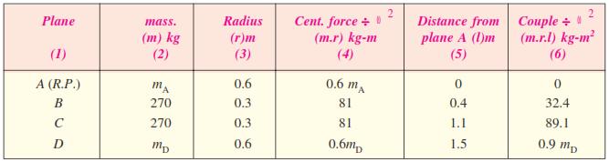
8 8. (a) A shaft carries four masses in parallel planes A, B, C and D in this order along its length. The masses at B and C are 18 kg and 12.5 kg respectively, and each has an eccentricity of 60 mm. The masses at A and D have an eccentricity of 80 mm. The angle between the masses at B and C is 100 and that between the masses at B and A is 190, both being measured in the same direction. The axial distance between the planes A and B is 100 mm and that between B and C is 200 mm. If the shaft is in complete dynamic balance. Determine: 1. The magnitude of the masses at A and D; 2. the distance between planes A and D ; and 3. the angular position of the mass at D. (N/D 14)
, draw OD parallel to vector c o to fix the direction of")
9 0.08 md.x = vector c o = kg-m 2... (i) In Fig. (b), draw OD parallel to vector c o to fix the direction of mass D.

10 9. (a) Four masses A, B, C and D as shown below are to be completely balanced. - A B C D Mass (kg) Radius (mm) The planes containing masses B and C are 300 mm apart. The angle between planes containing B and C is 90. B and C make angles of 210 and 120 respectively with D in the same sense. Find : 1. The magnitude and the angular position of mass A ; and 2. The position of planes A and D. (N/D 11)
 The following data apply to an outside cylinder uncoupled locomotive : Mass of rotating parts per cylinder = 360 kg ; Mass of reciprocating parts per cylinder = 300 kg ; Angle between cranks = 90")
11 2. Position of planes A and D 10. (a) The following data apply to an outside cylinder uncoupled locomotive : Mass of rotating parts per cylinder = 360 kg ; Mass of reciprocating parts per cylinder = 300 kg ; Angle between cranks = 90 ; Crank radius = 0.3 m ; Cylinder centres = 1.75 m ; Radius of balance masses = 0.75 m ; Wheel centres = 1.45 m. If whole of the rotating and two-thirds of reciprocating parts are to be balanced in planes of the driving wheels, find : 1. Magnitude and angular positions of balance masses, 2. Speed in kilometres per hour at which the wheel will lift off the rails when the load on each driving wheel is 30 kn and the diameter of tread of driving wheels is 1.8 m, and 3. Swaying couple at speed arrived at in (2) above. (N/D 13)

12 The vector co represents the balancing force and it is proportional to 0.75 mb. Therefore, by measurement, To determine the angular position of the balancing mass B, draw OB parallel to vector oc as shown Fig. (b). By measurement,

13 11. (b) A four crank engine has the two outer cranks set at 120 to each other, and their reciprocating masses are each 400 kg. The distance between the planes of rotation of adjacent cranks are 450 mm, 750 mm and 600 mm. If the engine is to be in complete primary balance, find the reciprocating mass and the relative angular position for each of the inner cranks. If the length of each crank is 300 mm, the length of each connecting rod is 1.2 m and the speed of rotation is 240 r.p.m., what is the maximum secondary unbalanced force? (N/D 12) Since the engine is to be in complete primary balance, therefore the primary couple polygon and the primary force polygon must close. First of all, the primary couple polygon, as shown in Fig.(c), is drawn to some suitable scale from the data given in Table (column 6), in order to find the reciprocating mass for crank 3. Now by measurement, we find that Now in order to find the reciprocating mass for crank 2, draw the primary force polygon, as shown in Fig.(d), to some suitable scale from the data given in Table (column 4). Now by measurement, we find that
14 Maximum secondary unbalanced force: The secondary crank positions obtained by rotating the primary cranks at twice the angle, is shown in Fig.(e). Now draw the secondary force polygon, as shown in Fig.( f ), to some suitable scale, from the data given in Table (column 4). The closing side of the polygon shown dotted in Fig.( f ) represents the maximum secondary unbalanced force. By measurement, we find that the maximum secondary unbalanced force is proportional to 582 kg-m. Maximum secondary unbalanced force 12. (b) The cranks and connecting rods of a 4 - cylinder in - line engine running at 1800 r.p.m. are 60 mm and 240 mm each respectively and the cylinders are spaced 150 mm apart. If the cylinders are numbered 1 to 4 in sequence from one end, the cranks appear at intervals of 90 in an end view in the order The reciprocating mass corresponding to each cylinder is 1.5 kg. Determine: 1. Unbalanced primary and secondary forces, if any, and 2. Unbalanced primary and secondary couples with reference to central plane of the engine. (N/D 11, A/M 11) 1. Unbalanced primary and secondary forces
.")
15 The primary force polygon from the data given in Table (column 4) is drawn as shown in Fig.(c). Since the primary force polygon is a closed figure, therefore there are no unbalanced primary forces. Ans. The secondary crank positions, taking crank 3 as the reference crank, is shown in Fig.(e). From the secondary force polygon as shown in Fig.( f ), we see that it is a closed figure. Therefore there are no unbalanced secondary forces. Ans. 2. Unbalanced primary and secondary couples The primary couple polygon from the data given in Table (column 6) is drawn as shown in Fig.(d). The closing side of the polygon, shown dotted in the figure, represents unbalanced primary couple. By measurement, we find the unbalanced primary couple is proportional to 0.19 kg-m 2. Unbalanced primary couple,
 A five cylinder in - line engine running at 750 r.p.m. has successive cranks 144 apart, the distance between the cylinder centre lines being 375 mm.")

16 The secondary couple polygon is shown in Fig.(g). The unbalanced secondary couple is shown by dotted line. By measurement, we find that unbalanced secondary couple is proportional to 0.54 kg-m 2. Unbalanced secondary couple, 13. (b) A five cylinder in - line engine running at 750 r.p.m. has successive cranks 144 apart, the distance between the cylinder centre lines being 375 mm. The piston stroke is 225 mm and the ratio of the connecting rod to the crank is 4. Examine the engine for balance of primary and secondary forces and couples. Find the maximum values of these and the position of the central crank at which these maximum values occur. The reciprocating mass for each cylinder is 15 kg. (N/D 14) Assuming the engine to be a vertical engine, the positions of the cylinders and the cranks are shown in Fig.(a), (b) and (c). The plane 3 may be taken as the reference plane and the crank 3 as the reference crank. The data may be tabulated as given in the following table. Now, draw the force and couple polygons for primary and secondary cranks as shown in Fig.(d), (e), ( f ), and (g). Since the primary and secondary force polygons are close, therefore the engine is balanced for primary and secondary forces. Ans.
17 Maximum unbalanced primary couple We know that the closing side of the primary couple polygon [shown dotted in Fig.(e)] gives the maximum unbalanced primary couple. By measurement, we find that maximum unbalanced primary couple is proportional to 1.62 kg-m 2. Maximum unbalanced primary couple, We see from Fig.(e) [shown by dotted line] that the maximum unbalanced primary couple occurs when crank 3 is at 90 from the line of stroke. Maximum unbalanced secondary couple We know that the closing side of the secondary couple polygon [shown dotted in Fig.(g)] gives the maximum unbalanced secondary couple. By measurement, we find that maximum unbalanced secondary couple is proportional to 2.7 kg-m 2. Maximum unbalanced secondary couple. We see from Fig.(g) that if the vector representing the unbalanced secondary couple (shown by dotted line) is rotated through 90, it will coincide with the line of stroke. Hence the original crank will be rotated through 45. Therefore, the maximum unbalanced secondary couple occurs when crank 3 is at 45 and at successive intervals of 90 (i.e. 135, 225 and 315 ) from the line of stroke. 14. (b) The three cylinders of an air compressor have their axes 120 to one another and their connecting rods are coupled to a single crank. The stroke is 100 mm and the length of each connecting rod is 150 mm. The mass of the reciprocating parts per cylinder is 1.5 kg. Find the maximum primary and secondary forces acting on the frame of the compressor when running at 3000 r.p.m. Describe clearly a method by which such forces may be balanced. (N/D 13) Maximum primary force acting on the frame of the compressor The primary direct and reverse crank positions as shown in Fig.(a) and (b), are obtained as discussed below : 1. Since θ = 0 for cylinder 1, therefore both the primary direct and reverse cranks will coincide with the common crank. 2. Since θ = ±120 for cylinder 2, therefore the primary direct crank is 120 clockwise and the primary reverse crank is 120 anti-clockwise from the line of stroke of cylinder Since θ = ± 240 for cylinder 3, therefore the primary direct crank is 240 clockwise and the primary reverse crank is 240 anti-clockwise from the line of stroke of cylinder 3.
18 From Fig.(b), we see that the primary reverse cranks form a balanced system. Therefore there is no unbalanced primary force due to the reverse cranks. From Fig.(a), we see that the resultant primary force is equivalent to the centrifugal force of a mass 3 m/2 attached to the end of the crank. The maximum primary force may be balanced by a mass attached diametrically opposite to the crank pin and rotating with the crank, of magnitude B1 at radius b1 such that Maximum secondary force acting on the frame of the compressor The secondary direct and reverse crank positions as shown in Fig.(a) and (b), are obtained as discussed below : 1. Since θ = 0 and 2 θ = 0 for cylinder 1, therefore both the secondary direct and reverse cranks will coincide with the common crank. 2. Since θ = ±120 and 2 θ = ± 240 for cylinder 2, therefore the secondary direct crank is 240 clockwise and the secondary reverse crank is 240 anticlockwise from the line of stroke of cylinder Since θ = ± 240 and 2 θ = ± 480, therefore the secondary direct crank is 480 or 120 clockwise and the secondary reverse crank is 480 or 120 anti-clockwise from the line of stroke of cylinder 3. This maximum secondary force may be balanced by a mass B2 at radius b2, attached diametrically opposite to the crankpin, and rotating anti-clockwise at twice the crank speed, such that
[You will experience the effect of a centrifugal force if you swing a mass on the end of a piece of string around in a circle.]
![[You will experience the effect of a centrifugal force if you swing a mass on the end of a piece of string around in a circle.]](/thumbs/85/92293367.jpg "[You will experience the effect of a centrifugal force if you swing a mass on the end of a piece of string around in a circle.]") Balancing Rotating Masses The balancing of rotating bodies is important to avoid the damaging effects of vibration. Vibrations are noisy and uncomfortable. For example, when a car wheel is out of balance,
Balancing Rotating Masses The balancing of rotating bodies is important to avoid the damaging effects of vibration. Vibrations are noisy and uncomfortable. For example, when a car wheel is out of balance,
Balancing of Rotating Masses
 Balancing of Rotating Masses 1 Balancing of Rotating Masses m Consider first a single mass m moving in a circular arc of radius r with an angular velocity rad/s. The mass has a centripetal (centre 2 seeking)
UNIT 2 KINEMATICS OF LINKAGE MECHANISMS
 UNIT 2 KINEMATICS OF LINKAGE MECHANISMS ABSOLUTE AND RELATIVE VELOCITY An absolute velocity is the velocity of a point measured from a fixed point (normally the ground or anything rigidly attached to the
Dynamics of Machinery
 Dynamics of Machinery Two Mark Questions & Answers Varun B Page 1 Force Analysis 1. Define inertia force. Inertia force is an imaginary force, which when acts upon a rigid body, brings it to an equilibrium
This equation of motion may be solved either by differential equation method or by graphical method as discussed below:
 2.15. Frequency of Under Damped Forced Vibrations Consider a system consisting of spring, mass and damper as shown in Fig. 22. Let the system is acted upon by an external periodic (i.e. simple harmonic)
Balancing of Masses. 1. Balancing of a Single Rotating Mass By a Single Mass Rotating in the Same Plane
 lecture - 1 Balancing of Masses Theory of Machine Balancing of Masses A car assembly line. In this chapter we shall discuss the balancing of unbalanced forces caused by rotating masses, in order to minimize
UNIT-I (FORCE ANALYSIS)
") DHANALAKSHMI SRINIVASAN INSTITUTE OF RESEACH AND TECHNOLOGY DEPARTMENT OF MECHANICAL ENGINEERING QUESTION BANK ME2302 DYNAMICS OF MACHINERY III YEAR/ V SEMESTER UNIT-I (FORCE ANALYSIS) PART-A (2 marks)
DHANALAKSHMI SRINIVASAN INSTITUTE OF RESEACH AND TECHNOLOGY DEPARTMENT OF MECHANICAL ENGINEERING QUESTION BANK ME2302 DYNAMICS OF MACHINERY III YEAR/ V SEMESTER UNIT-I (FORCE ANALYSIS) PART-A (2 marks)
DYNAMICS OF MACHINES By. Dr.K.SRINIVASAN, Professor, AU-FRG Inst.for CAD/CAM, Anna University BALANCING OF RECIPROCATING MASSES
 DYNAMICS OF MACHINES By Dr.K.SRINIVASAN, Professor, AU-FRG Inst.for CAD/CAM, Anna University BALANCING OF RECIPROCATING MASSES SINGLE CYLINDER ENGINE IN-LINE ENGINES- 3, 4,5, 6 cylinders are Common V-ENGINES
Static Unbalance. Both bearing reactions occur in the same plane and in the. After balancing no bearing reaction remains theoretically.
 BALANCING Static Unbalance A disk-shaft system on rigid rails An unbalanced disk-shaft system mounted on bearings and rotated For the unbalanced rotating system: Dynamic Bearing Reactions + Inertia Forces
Kinematics of. Motion. 8 l Theory of Machines
 8 l Theory of Machines Features 1. 1ntroduction.. Plane Motion. 3. Rectilinear Motion. 4. Curvilinear Motion. 5. Linear Displacement. 6. Linear Velocity. 7. Linear Acceleration. 8. Equations of Linear
ENGINEERING COUNCIL DYNAMICS OF MECHANICAL SYSTEMS D225 TUTORIAL 8 BALANCING OF ROTATING BODIES
 ENGINEERING COUNCIL DYNAMICS OF MECHANICAL SYSTEMS D225 TUTORIAL 8 BALANCING OF ROTATING BODIES On completion of this tutorial you should be able to do the following. Explain the importance of balancing.
ME2302 DYNAMICS OF MACHINERY
 ME2302 DYNAMICS OF MACHINERY TWO MARKS QUESTION AND ANSWERS 1. What are the conditions for a body to be in static and dynamic equilibrium? Necessary and sufficient conditions for static and dynamic equilibrium
Inertia Forces in a Reciprocating Engine, Considering the Weight of Connecting Rod.
 Inertia Forces in a Reciprocating Engine, Considering the Weight of Connecting Rod. We use equivalent mass method. let OC be the crank and PC, the connecting rod whose centre of gravity lies at G. We will
TOPIC : 8 : Balancing
 TOPIC : 8 : Balancing --------------------------------------------------------------- Q.1. What is balancing? What are its objectives? What are types of balancing? BALANCING: Balancing is the technique
UNIT 4 FLYWHEEL 4.1 INTRODUCTION 4.2 DYNAMICALLY EQUIVALENT SYSTEM. Structure. Objectives. 4.1 Introduction
 UNIT 4 FLYWHEEL Structure 4.1 Introduction Objectives 4. Dynamically Equivalent System 4.3 Turning Moment Diagram 4.3.1 Turning Moment Diagram of a Single Cylinder 4-storke IC Engine 4.3. Turning Moment
EDEXCEL NATIONAL CERTIFICATE/DIPLOMA ADVANCED MECHANICAL PRINCIPLES AND APPLICATIONS UNIT 18 NQF LEVEL 3
 EDEXCEL NATIONAL CERTIFICATE/DIPLOMA ADVANCED MECHANICAL PRINCIPLES AND APPLICATIONS UNIT 18 NQF LEVEL 3 OUTCOME 3 BE ABLE TO DETERMINE RELATIVE AND RESULTANT VELOCITY IN ENGINEERING SYSTEMS Resultant
SILVER OAK COLLEGE OF ENGINEERING & TECHNOLOGY
 BE - SEMESTER VI MID SEMESTER EXAMINATION SUMMER 2015 SUBJECT: DYNAMICS OF MACHINERY (161901) DATE: 09-03-2015 TIME: 02:00 pm to 03:13 pm TOTAL MARKS: 30 Q.1 (a) Define the following terms in short: (i)
10/23/2015. Chapter 7. Velocity in Mechanisms. (Relative Velocity Method) Mohammad Suliman Abuhaiba, Ph.D., PE
 Mohammad Suliman Abuhaiba, Ph.D., PE") Chapter 7 Velocity in Mechanisms (Relative Velocity Method) 1 2 7.2. Relative Velocity of Two Bodies Moving in Straight Lines 3 7.3. Motion of a Link Velocity of any point on a link wrt another point on
Chapter 7 Velocity in Mechanisms (Relative Velocity Method) 1 2 7.2. Relative Velocity of Two Bodies Moving in Straight Lines 3 7.3. Motion of a Link Velocity of any point on a link wrt another point on
Inertia Forces in Reciprocating. Parts. 514 l Theory of Machines
 514 l Theory of Machines 15 Features 1. Introduction.. Resultant Effect of a System of Forces Acting on a Rigid Body. 3. D-Alembert s Principle. 4. Velocity and Acceleration of the Reciprocating Parts
Department of Mechanical Engineering ME6505- DYNAMICS OF MACHINES. Two Marks Question and answer UNIT I FORCE ANALYSIS AND FLYWHEELS
 Department of Mechanical Engineering ME6505- DYNAMICS OF MACHINES Two Marks Question and answer UNIT I FORCE ANALYSIS AND FLYWHEELS 1. Distinguish between space diagram and free body diagram Space Diagram
Where, m = slope of line = constant c = Intercept on y axis = effort required to start the machine
 (ISO/IEC - 700-005 Certified) Model Answer: Summer 07 Code: 70 Important Instructions to examiners: ) The answers should be examined by key words and not as word-to-word as given in the model answer scheme.
Flywheels-Function need and Operation
 STUDY OF FLYWHEEL Flywheel definition A flywheel is an inertial energy-storage device. It absorbs mechanical energy and serves as a reservoir, storing energy during the period when the supply of energy
1. Replace the given system of forces acting on a body as shown in figure 1 by a single force and couple acting at the point A.
 Code No: Z0321 / R07 Set No. 1 I B.Tech - Regular Examinations, June 2009 CLASSICAL MECHANICS ( Common to Mechanical Engineering, Chemical Engineering, Mechatronics, Production Engineering and Automobile
DYNAMICS OF MACHINERY
 DYNAMICS OF MACHINERY B.TECH. DEGREE COURSE SCHEME AND SYLLABUS (00-03 ADMISSION ONWARDS) MAHATMA GANDHI UNIVERSITY KOTTAYAM, KERALA DYNAMICS OF MACHINERY Module 1 Balancing: - Balancing of rotating masses,
UNIT 4 Balancing of Rotating Masses
 UNIT 4 Balancing of Rotating Masses 1.A shaft is supported in bearings 1.8 meter apart and projects 0.45 meter beyond bearings at each end. The shaft carries three pulleys one at each end and one at middle
Chapter 8 Acceleration in Mechanisms
 Chapter 8 Acceleration in Mechanisms 1 2 8.2. Acceleration Diagram for a Link Example 8.1 3 The crank of a slider crank mechanism rotates cw at a constant speed of 300 rpm. The crank is 150 mm & the ConRod
Mechanical Vibrations Prof. Rajiv Tiwari Department of Mechanical Engineering Indian Institute of Technology, Guwahati
 Mechanical Vibrations Prof. Rajiv Tiwari Department of Mechanical Engineering Indian Institute of Technology, Guwahati Module - 12 Signature analysis and preventive maintenance Lecture - 3 Field balancing
C7047. PART A Answer all questions, each carries 5 marks.
 7047 Reg No.: Total Pages: 3 Name: Max. Marks: 100 PJ DUL KLM TEHNOLOGIL UNIVERSITY FIRST SEMESTER.TEH DEGREE EXMINTION, DEEMER 2017 ourse ode: E100 ourse Name: ENGINEERING MEHNIS PRT nswer all questions,
Dept of ECE, SCMS Cochin
 B B2B109 Pages: 3 Reg. No. Name: APJ ABDUL KALAM TECHNOLOGICAL UNIVERSITY SECOND SEMESTER B.TECH DEGREE EXAMINATION, MAY 2017 Course Code: BE 100 Course Name: ENGINEERING MECHANICS Max. Marks: 100 Duration:
RIGID BODY MOTION (Section 16.1)
") RIGID BODY MOTION (Section 16.1) There are cases where an object cannot be treated as a particle. In these cases the size or shape of the body must be considered. Rotation of the body about its center
RIGID BODY MOTION (Section 16.1) There are cases where an object cannot be treated as a particle. In these cases the size or shape of the body must be considered. Rotation of the body about its center
Dynamics of the Swash Plate Mechanism
 Purdue University Purdue e-pubs nternational Compressor Engineering Conference School of Mechanical Engineering 1984 Dynamics of the Swash Plate Mechanism J. F. Below D. A. Miloslavich Follow this and
SUMMER 14 EXAMINATION
 Important Instructions to examiners: 1) The answers should be examined by key words and not as word-to-word as given in the model answer scheme. 2) The model answer and the answer written by candidate
The University of Melbourne Engineering Mechanics
 The University of Melbourne 436-291 Engineering Mechanics Tutorial Eleven Instantaneous Centre and General Motion Part A (Introductory) 1. (Problem 5/93 from Meriam and Kraige - Dynamics) For the instant
Dynamics Plane kinematics of rigid bodies Section 4: TJW Rotation: Example 1
 Section 4: TJW Rotation: Example 1 The pinion A of the hoist motor drives gear B, which is attached to the hoisting drum. The load L is lifted from its rest position and acquires an upward velocity of
DEPARTMENT OF MECHANICAL ENGINEERING Dynamics of Machinery. Submitted
 DEPARTMENT OF MECHANICAL ENGINEERING Dynamics of Machinery Submitted 1 UNIT I - Force Analysis INDEX (1) Introduction (2) Newton s Law (3) Types of force Analysis (4) Principle of Super Position (5) Free
Varuvan Vadivelan. Institute of Technology LAB MANUAL. : 2013 : B.E. MECHANICAL ENGINEERING : III Year / V Semester. Regulation Branch Year & Semester
 Varuvan Vadivelan Institute of Technology Dharmapuri 636 703 LAB MANUAL Regulation Branch Year & Semester : 2013 : B.E. MECHANICAL ENGINEERING : III Year / V Semester ME 6511 - DYNAMICS LABORATORY GENERAL
 Subject : Engineering Mechanics Subject Code : 1704 Page No: 1 / 6 ----------------------------- Important Instructions to examiners: 1) The answers should be examined by key words and not as word-to-word
ME6505 Dynamics of Machines Mechanical Engineering
 DHANALAKSHMI COLLEGE OF ENGINEERING UNIT I FORCE ANALYSIS 1. State D Alembert s principle for dynamic equilibrium and identify its significance D Alembert s principle states that the inertia forces and
The principle of the flywheel is found before the many centuries ago in spindle and the potter's wheel.
 TOM Fly Wheel Mechanical Engineering Department The principle of the flywheel is found before the many centuries ago in spindle and the potter's wheel. A heavy-rimmed rotating wheel used to minimize variations
ENGINEERING MECHANICS SOLUTIONS UNIT-I
 LONG QUESTIONS ENGINEERING MECHANICS SOLUTIONS UNIT-I 1. A roller shown in Figure 1 is mass 150 Kg. What force P is necessary to start the roller over the block A? =90+25 =115 = 90+25.377 = 115.377 = 360-(115+115.377)
UNIT 5 GOVERNORS 5.1 INTRODUCTION. Structure. 5.1 Introduction. 5.2 Classification of Governors 5.3 Gravity Controlled Centrifugal Governors
 UNIT 5 GVERNRS Governors Structure 5. Introduction bjectives 5. lassification of Governors 5.3 Gravity ontrolled entrifugal Governors 5.3. Watt Governor 5.3. Porter Governor 5.4 Spring ontrolled entrifugal
OUTCOME 1 MECHANICAL POWER TRANSMISSION SYSTEMS TUTORIAL 3 FLYWHEELS. On completion of this short tutorial you should be able to do the following.
 Unit 60: Dynamics of Machines Unit code: H/60/4 QCF Level:4 Credit value:5 OUTCOME MECHANCAL POWER TRANSMSSON SYSTEMS TUTORAL 3 FLYWHEELS. Be able to determine the kinetic and dynamic parameters of mechanical
DYNAMICS MOMENT OF INERTIA
 DYNAMICS MOMENT OF INERTIA S TO SELF ASSESSMENT EXERCISE No.1 1. A cylinder has a mass of 1 kg, outer radius of 0.05 m and radius of gyration 0.03 m. It is allowed to roll down an inclined plane until
20k rad/s and 2 10k rad/s,
 ME 35 - Machine Design I Summer Semester 0 Name of Student: Lab Section Number: FINAL EXAM. OPEN BOOK AND CLOSED NOTES. Thursday, August nd, 0 Please show all your work for your solutions on the blank
Tuesday, February 11, Chapter 3. Load and Stress Analysis. Dr. Mohammad Suliman Abuhaiba, PE
 1 Chapter 3 Load and Stress Analysis 2 Chapter Outline Equilibrium & Free-Body Diagrams Shear Force and Bending Moments in Beams Singularity Functions Stress Cartesian Stress Components Mohr s Circle for
DYNAMICS ME HOMEWORK PROBLEM SETS
 DYNAMICS ME 34010 HOMEWORK PROBLEM SETS Mahmoud M. Safadi 1, M.B. Rubin 2 1 safadi@technion.ac.il, 2 mbrubin@technion.ac.il Faculty of Mechanical Engineering Technion Israel Institute of Technology Spring
ME Machine Design I
 ME 5 - Machine Design I Summer Semester 008 Name Lab. Div. EXAM. OEN BOOK AND CLOSED NOTES. Wednesday, July 16th, 008 Write your solutions on the blank paper that is provided. Write on one side of the
AP Physics QUIZ Chapters 10
 Name: 1. Torque is the rotational analogue of (A) Kinetic Energy (B) Linear Momentum (C) Acceleration (D) Force (E) Mass A 5-kilogram sphere is connected to a 10-kilogram sphere by a rigid rod of negligible
UNIT II Fig (1) Fig (1)
 Fig (1)") UNIVERSITY OF PUNE [4362]-116 S.E.(Mechanical / Automobile) Examination 2013 (2008 pattern) THEY OF MACHINES -1 [Total No. of Questions: 12] [Total No. of Printed pages: 7] [Time: 4 Hours] [Max. Marks:
UNIVERSITY OF PUNE [4362]-116 S.E.(Mechanical / Automobile) Examination 2013 (2008 pattern) THEY OF MACHINES -1 [Total No. of Questions: 12] [Total No. of Printed pages: 7] [Time: 4 Hours] [Max. Marks:
Cams. 774 l Theory of Machines
 774 l Theory of Machines 0 Fea eatur tures es 1. Introduction.. Classification of Followers. 3. Classification of Cams. 4. Terms used in Radial cams. 5. Motion of the Follower. 6. Displacement, Velocity
b) 2/3 MR 2 c) 3/4MR 2 d) 2/5MR 2
 2/3 MR 2 c) 3/4MR 2 d) 2/5MR 2") Rotational Motion 1) The diameter of a flywheel increases by 1%. What will be percentage increase in moment of inertia about axis of symmetry a) 2% b) 4% c) 1% d) 0.5% 2) Two rings of the same radius and
Rotational Motion 1) The diameter of a flywheel increases by 1%. What will be percentage increase in moment of inertia about axis of symmetry a) 2% b) 4% c) 1% d) 0.5% 2) Two rings of the same radius and
Rotational Kinematics and Dynamics. UCVTS AIT Physics
 Rotational Kinematics and Dynamics UCVTS AIT Physics Angular Position Axis of rotation is the center of the disc Choose a fixed reference line Point P is at a fixed distance r from the origin Angular Position,
TUTORIAL SHEET 1. magnitude of P and the values of ø and θ. Ans: ø =74 0 and θ= 53 0
 TUTORIAL SHEET 1 1. The rectangular platform is hinged at A and B and supported by a cable which passes over a frictionless hook at E. Knowing that the tension in the cable is 1349N, determine the moment
3.1 CONDITIONS FOR RIGID-BODY EQUILIBRIUM
 3.1 CONDITIONS FOR RIGID-BODY EQUILIBRIUM Consider rigid body fixed in the x, y and z reference and is either at rest or moves with reference at constant velocity Two types of forces that act on it, the
Anna University May/June 2013 Exams ME2151 Engineering Mechanics Important Questions.
 Anna University May/June 2013 Exams ME2151 Engineering Mechanics Important Questions 1. Find the resultant force and its direction for the given figure 2. Two forces are acting at a point O as shown in
VALLIAMMAI ENGINEERING COLLEGE SRM NAGAR, KATTANKULATHUR DEPARTMENT OF MECHANICAL ENGINEERING
 VALLIAMMAI ENGINEERING COLLEGE SRM NAGAR, KATTANKULATHUR 603203 DEPARTMENT OF MECHANICAL ENGINEERING BRANCH: MECHANICAL YEAR / SEMESTER: I / II UNIT 1 PART- A 1. State Newton's three laws of motion? 2.
PLANAR KINETICS OF A RIGID BODY FORCE AND ACCELERATION
 PLANAR KINETICS OF A RIGID BODY FORCE AND ACCELERATION I. Moment of Inertia: Since a body has a definite size and shape, an applied nonconcurrent force system may cause the body to both translate and rotate.
Fig. 6.1 Plate or disk cam.
 CAMS INTRODUCTION A cam is a mechanical device used to transmit motion to a follower by direct contact. The driver is called the cam and the driven member is called the follower. In a cam follower pair,
Code No: R Set No. 1
 Code No: R05010302 Set No. 1 I B.Tech Supplimentary Examinations, February 2008 ENGINEERING MECHANICS ( Common to Mechanical Engineering, Mechatronics, Metallurgy & Material Technology, Production Engineering,
PLANAR RIGID BODY MOTION: TRANSLATION &
 PLANAR RIGID BODY MOTION: TRANSLATION & Today s Objectives : ROTATION Students will be able to: 1. Analyze the kinematics of a rigid body undergoing planar translation or rotation about a fixed axis. In-Class
of the four-bar linkage shown in Figure 1 is T 12
 ME 5 - Machine Design I Fall Semester 0 Name of Student Lab Section Number FINL EM. OPEN BOOK ND CLOSED NOTES Wednesday, December th, 0 Use the blank paper provided for your solutions write on one side
UNIT 6 GOVERNORS. 6.5 Controlling force and and stability of spring controlled Governors. Compiled By. Dr. B. Suresha, Professor
 UNIT 6 GOVERNORS STRUCTURE 6.1 Introduction 6.1.1 Objectives 6. Types of Governors 6..1 Porter Governor 6.. Hartnell Governor 6.3 Governor effort and Power 6.4 Characteristics of Governors 6.5 Controlling
Vidyalanakar F.Y. Diploma : Sem. II [AE/CE/CH/CR/CS/CV/EE/EP/FE/ME/MH/MI/PG/PT/PS] Engineering Mechanics
![Vidyalanakar F.Y. Diploma : Sem. II [AE/CE/CH/CR/CS/CV/EE/EP/FE/ME/MH/MI/PG/PT/PS] Engineering Mechanics](/thumbs/77/74871041.jpg "Vidyalanakar F.Y. Diploma : Sem. II [AE/CE/CH/CR/CS/CV/EE/EP/FE/ME/MH/MI/PG/PT/PS] Engineering Mechanics") Vidyalanakar F.Y. Diploma : Sem. II [AE/CE/CH/CR/CS/CV/EE/EP/FE/ME/MH/MI/PG/PT/PS] Engineering Mechanics Time : 3 Hrs.] Prelim Question Paper Solution [Marks : 100 Q.1 Attempt any TEN of the following
Vidyalanakar F.Y. Diploma : Sem. II [AE/CE/CH/CR/CS/CV/EE/EP/FE/ME/MH/MI/PG/PT/PS] Engineering Mechanics Time : 3 Hrs.] Prelim Question Paper Solution [Marks : 100 Q.1 Attempt any TEN of the following
Q 100 OA = 30 AB = 80 BQ = 100 BC = rpm. All dimensions are in mm
 rolem 6: A toggle mechanism is shown in figure along with the diagrams of the links in mm. find the velocities of the points B and C and the angular velocities of links AB, BQ and BC. The crank rotates
LABORATORY MANUAL DYNAMICS OF MACHINE ME-314-E
 LABORATORY MANUAL DYNAMICS OF MACHINE ME-314-E 1 LIST OF EXPERIMENTS S. No. NAME OF EXPERIMENTS PAGE No. 1. To perform experiment on watt and Porter Governors to prepare performance characteristic Curves,
Q.1 a) any six of the following 6x2= 12. i) Define - ( Each term 01 mark)
 any six of the following 6x2= 12. i) Define - ( Each term 01 mark)") Important Instructions to examiners: 1) The answers should be examined by key words and not as word-to-word as given in the model answer scheme. 2) The model answer and the answer written by candidate
Important Instructions to examiners: 1) The answers should be examined by key words and not as word-to-word as given in the model answer scheme. 2) The model answer and the answer written by candidate
Statics Chapter II Fall 2018 Exercises Corresponding to Sections 2.1, 2.2, and 2.3
 Statics Chapter II Fall 2018 Exercises Corresponding to Sections 2.1, 2.2, and 2.3 2 3 Determine the magnitude of the resultant force FR = F1 + F2 and its direction, measured counterclockwise from the
The case where there is no net effect of the forces acting on a rigid body
 The case where there is no net effect of the forces acting on a rigid body Outline: Introduction and Definition of Equilibrium Equilibrium in Two-Dimensions Special cases Equilibrium in Three-Dimensions
MECHANICAL ENGINEERING
 MECHNICL ENGINEERING ESE TOPICWISE OBJECTIVE SOLVED PPER-II FROM (1995-017) UPSC Engineering Services Examination State Engineering Service Examination & Public Sector Examination. IES MSTER PUBLICTION
Exam 2, Phy 2049, Spring Solutions:
 Exam 2, Phy 2049, Spring 2017. Solutions: 1. A battery, which has an emf of EMF = 10V and an internal resistance of R 0 = 50Ω, is connected to three resistors, as shown in the figure. The resistors have
2008 FXA THREE FORCES IN EQUILIBRIUM 1. Candidates should be able to : TRIANGLE OF FORCES RULE
 THREE ORCES IN EQUILIBRIUM 1 Candidates should be able to : TRIANGLE O ORCES RULE Draw and use a triangle of forces to represent the equilibrium of three forces acting at a point in an object. State that
Dynamics of Machinery
 1 Preamble Dynamics of Machinery Relation between motion and forces causing is a fascinating subject. This study is a generally referred as dynamic. Modern Engineering aims at analysing and predicting
Angles and Applications
 CHAPTER 1 Angles and Applications 1.1 Introduction Trigonometry is the branch of mathematics concerned with the measurement of the parts, sides, and angles of a triangle. Plane trigonometry, which is the
PES Institute of Technology
 PES Institute of Technology Bangalore south campus, Bangalore-5460100 Department of Mechanical Engineering Faculty name : Madhu M Date: 29/06/2012 SEM : 3 rd A SEC Subject : MECHANICS OF MATERIALS Subject
Gyroscopic Couple and Precessional Motion
 480 l Theory of Machines 14 Fea eatur tures es 1. Introduction.. Precessional Angular Motion. 3. Gyroscopic Couple. 4. Effect of Gyroscopic Couple on an Aeroplane. 5. Terms Used in a Naval Ship. 6. Effect
Chapter 3 Velocity Analysis
 Chapter 3 Velocity nalysis The position of point with respect to 0, Fig 1 may be defined mathematically in either polar or Cartesian form. Two scalar quantities, the length R and the angle θ with respect
This, of course, is simply a restatement of Newton's law as discussed in Section 10.1 (p. 491).
.") 12.0 INTRODUCTION Any link or member that is in pure rotation can, theoretically, be perfectly balanced to eliminate all shaking forces and shaking moments. It is accepted design practice to balance all
12.0 INTRODUCTION Any link or member that is in pure rotation can, theoretically, be perfectly balanced to eliminate all shaking forces and shaking moments. It is accepted design practice to balance all
Unit Workbook 4 - Level 4 ENG U8 Mechanical Principles 2018 UniCourse Ltd. All Rights Reserved. Sample
 Pearson BTEC Level 4 Higher Nationals in Engineering (RQF) Unit 8: Mechanical Principles Unit Workbook 2 in a series of 4 for this unit Learning Outcome 2 Dynamic Mechanical Systems Page 1 of 17 1.3 Work
Shear force and bending moment of beams 2.1 Beams 2.2 Classification of beams 1. Cantilever Beam Built-in encastre' Cantilever
 CHAPTER TWO Shear force and bending moment of beams 2.1 Beams A beam is a structural member resting on supports to carry vertical loads. Beams are generally placed horizontally; the amount and extent of
7.6 Journal Bearings
 7.6 Journal Bearings 7.6 Journal Bearings Procedures and Strategies, page 1 of 2 Procedures and Strategies for Solving Problems Involving Frictional Forces on Journal Bearings For problems involving a
TOPIC D: ROTATION EXAMPLES SPRING 2018
 TOPIC D: ROTATION EXAMPLES SPRING 018 Q1. A car accelerates uniformly from rest to 80 km hr 1 in 6 s. The wheels have a radius of 30 cm. What is the angular acceleration of the wheels? Q. The University
Model Answers Attempt any TEN of the following :
 (ISO/IEC - 70-005 Certified) Model Answer: Winter 7 Sub. Code: 17 Important Instructions to Examiners: 1) The answers should be examined by key words and not as word-to-word as given in the model answer
FALL TERM EXAM, PHYS 1211, INTRODUCTORY PHYSICS I Thursday, 11 December 2014, 6 PM to 9 PM, Field House Gym
 FALL TERM EXAM, PHYS 1211, INTRODUCTORY PHYSICS I Thursday, 11 December 2014, 6 PM to 9 PM, Field House Gym NAME: STUDENT ID: INSTRUCTION 1. This exam booklet has 13 pages. Make sure none are missing 2.
OUTCOME 2 KINEMATICS AND DYNAMICS
 Unit 60: Dynamics of Machines Unit code: H/601/1411 QCF Level:4 Credit value:15 OUTCOME 2 KINEMATICS AND DYNAMICS TUTORIAL 3 GYROSCOPES 2 Be able to determine the kinetic and dynamic parameters of mechanical
Two Dimensional State of Stress and Strain: examples
 Lecture 1-5: Two Dimensional State of Stress and Strain: examples Principal stress. Stresses on oblique plane: Till now we have dealt with either pure normal direct stress or pure shear stress. In many
The Moment of a Force
 The Moment of a Force When we consider cases where forces act on a body of non-zero size (i.e. not a particle), the main new aspect that we need to take account of is that such a body can rotate, as well
BE Semester- I ( ) Question Bank (MECHANICS OF SOLIDS)
 Question Bank (MECHANICS OF SOLIDS)") BE Semester- I ( ) Question Bank (MECHANICS OF SOLIDS) All questions carry equal marks(10 marks) Q.1 (a) Write the SI units of following quantities and also mention whether it is scalar or vector: (i)
BE Semester- I ( ) Question Bank (MECHANICS OF SOLIDS) All questions carry equal marks(10 marks) Q.1 (a) Write the SI units of following quantities and also mention whether it is scalar or vector: (i)
Downloaded from Downloaded from / 1
 PURWANCHAL UNIVERSITY III SEMESTER FINAL EXAMINATION-2002 LEVEL : B. E. (Civil) SUBJECT: BEG256CI, Strength of Material Full Marks: 80 TIME: 03:00 hrs Pass marks: 32 Candidates are required to give their
Quantitative Skills in AP Physics 1
 This chapter focuses on some of the quantitative skills that are important in your AP Physics 1 course. These are not all of the skills that you will learn, practice, and apply during the year, but these
Two small balls, each of mass m, with perpendicular bisector of the line joining the two balls as the axis of rotation:
 PHYSCS LOCUS 17 summation in mi ri becomes an integration. We imagine the body to be subdivided into infinitesimal elements, each of mass dm, as shown in figure 7.17. Let r be the distance from such an
Brakes and Dynamometers
 73 l Theory of Machines 19 Features 1. Introduction. Materials for Brake Lining. 3. Types of Brakes. 4. Single Block or Shoe Brake. 5. Pivoted Block or Shoe Brake. 6. Double Block or Shoe Brake. 7. Simple
Plane Motion of Rigid Bodies: Forces and Accelerations
 Plane Motion of Rigid Bodies: Forces and Accelerations Reference: Beer, Ferdinand P. et al, Vector Mechanics for Engineers : Dynamics, 8 th Edition, Mc GrawHill Hibbeler R.C., Engineering Mechanics: Dynamics,
When a rigid body is in equilibrium, both the resultant force and the resultant couple must be zero.
 When a rigid body is in equilibrium, both the resultant force and the resultant couple must be zero. 0 0 0 0 k M j M i M M k R j R i R F R z y x z y x Forces and moments acting on a rigid body could be
Chapter 4 Force System Resultant Moment of a Force
 Chapter 4 Force System Resultant Moment of a Force MOMENT OF A FORCE SCALAR FORMULATION, CROSS PRODUCT, MOMENT OF A FORCE VECTOR FORMULATION, & PRINCIPLE OF MOMENTS Today s Objectives : Students will be
Handout 6: Rotational motion and moment of inertia. Angular velocity and angular acceleration
 1 Handout 6: Rotational motion and moment of inertia Angular velocity and angular acceleration In Figure 1, a particle b is rotating about an axis along a circular path with radius r. The radius sweeps
Reg. No. : Question Paper Code : B.E./B.Tech. DEGREE EXAMINATION, NOVEMBER/DECEMBER Second Semester.
 Ws11 Reg. No. : Question Paper Code : 27275 B.E./B.Tech. DEGREE EXAMINATION, NOVEMBER/DECEMBER 2015. Second Semester Civil Engineering GE 6253 ENGINEERING MECHANICS (Common to all branches except Electrical
ME Machine Design I. EXAM 1. OPEN BOOK AND CLOSED NOTES. Wednesday, September 30th, 2009
 ME - Machine Design I Fall Semester 009 Name Lab. Div. EXAM. OPEN BOOK AND CLOSED NOTES. Wednesday, September 0th, 009 Please use the blank paper provided for your solutions. Write on one side of the paper
Columns and Struts. 600 A Textbook of Machine Design
 600 A Textbook of Machine Design C H A P T E R 16 Columns and Struts 1. Introduction.. Failure of a Column or Strut. 3. Types of End Conditions of Columns. 4. Euler s Column Theory. 5. Assumptions in Euler
Sub. Code:
 Important Instructions to examiners: ) The answers should be examined by key words and not as word-to-word as given in the model answer scheme. ) The model answer and the answer written by candidate may
EQUATIONS OF EQUILIBRIUM & TWO-AND THREE-FORCE MEMEBERS
 EQUATIONS OF EQUILIBRIUM & TWO-AND THREE-FORCE MEMEBERS Today s Objectives: Students will be able to: a) Apply equations of equilibrium to solve for unknowns, and, b) Recognize two-force members. READING