A design Model for Pile Walls Used to Stabilize Landslides
|
|
|
- Stewart Harrington
- 5 years ago
- Views:
Transcription
1 WV DOH RP #121 Experimental and Analytical Behavior of Slide Suppressors Embedded in Bedrock A design Model for Pile Walls Used to Stabilize Landslides By: Tia Maria Richardson, P.E. Principal Investigator
2 *Landslides are a common problem in WV Pile Walls *Are often used by the WV DOH as a soil reinforcement technique to remediate failed slopes *They can be placed in lieu of traditional earth retaining structures *The are particularly useful when space is limited *Often referred to as Slide Suppressors
3 Usually consist of pre-cast concrete panels supported by drilled or driven piers Other lagging has also been used Greenbag Road Morgantown, WV
4 They transfer the load from the weak upper strata to the stable material below Lagging (in this application) not structural Purpose: *Aesthetics Contain loose debris
5 Piles MUST Penetrate the Slip Surface Must be embedded to fixity - into a stable material that is sufficiently strong to resist the landslide forces Subsurface data is a MUST!
6 Subsurface data is a MUST! Driven to Refusal Top of Rock Slip surface BELOW Top of Rock
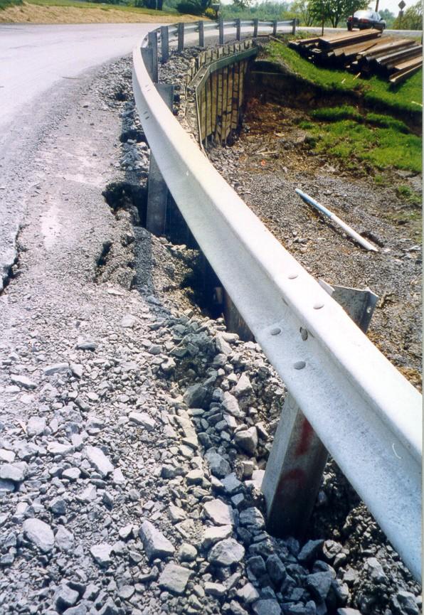
7 Pile Wall Failure Rt. 857, Morgantown, WV (Cheat Lake Area)

8
9
10 Stable material below Rock?? Not always! WV has a lot of Inter-bedded weak clay seams in shale SITE specific!
11 In a landslide situation The Design & Analysis Requires Defining Two Main Variables: 1) The driving forces from the landslide 2) The passive resistance provided by placing the piles WILL COME BACK TO THIS!
12 RP #97 - Dr. M.A. Gabr Graduate Student DOH Installing piles into rock 10 feet or L/3 Conservative Approach
13 Fu EI1, L1 LTBASE Pile Program Curves Developed by Dr. Gabr EI2, L2 Thesis: Develop a Soil Curve Allowable deformation Deformation
14 Hyperbolic Shear - Stress Shear - Strain Relationship Fu TOR Unbalanced Force, Fu VERY Theoretical!
15 Test Site Bridgeport, WV Rt. 73/73

16 Bridgeport, WV Rt. 73/73 Landslide

17 Road Closed!

18

19 Magnitude of Cracks

20 Dead Man

21 Custom built a frame to house the dial gauges

22 Also strained gauged along its length
23 Rt. 73/73 Test Site Validated LTBASE for a load at the top via strain gauges and dial gauges Demonstrated that after the point of fixity is reached - increased pile length does not reduce movements *Phase II: Demonstrated it actually increases bending moment & movement at the top
 Phase II")
24 Inclinometer cut to size (or shorter) Phase II Phase I


25 L L
26 What you are measuring with the instrument *Important!
27 0 Tygart Lake - Test Hole #2 - A-Plane Pipe Bent Deflection (inches) *Keep in mind the rigid piles will move different than flexible soil Will see both soil movement data and pile movement data throughout this presentation Slip plane (soil movement) Cumulative deflection Depth (feet) Incremental data /16/1998 2/19/1998 3/19/1998 5/19/1998 Cumulative
28 *Full Scale Performance Monitoring 2 Sites: Green Bag Road And Forest Ave Full Scale Test Site Tygart Lake
29 109 Piles in the wall Embedded in Lacustrine Clay on a 1 0 batter Total Pile Lengths = 30 Feet ~7 ft. above centerline, ~2 ft. above G.S. in the back Monitoring 3 piles in the wall # 29, 49 and 73 And 2 test piles on end feet long

30 GBR Old pipe piles
31 Generic Profile View Piles at toe of slope

32 Installation of Pile #29 Green Bag Road Morgantown, WV

33

34
35 Inclinometer Pipe *Position* Plane of maximum movement
36
37 Pile #49 and Test Pile #2 show the most movement Pile Size Pile #73 Pile #49 Pile #29 Test Piles H 12x53 ASTM A-36 Carbon Grade Steel Plan View
38 Depth (feet) Greenbag Road - Test Hole #2 A-Plane Cumulative at Pile Top 0.4 Inches Deflection (inches) Green Bag Road Maximum Movement ~ 0.6 Inches Pile #49 Near the center of the wall Test Pile #2 ~ 0.3 Inches Depth (feet) Greenbag Road Test Hole #4 - PILE #49 - A-Plane Cumulative at Pile Top ~ 0.6 Inches Deflection (inches) 32 5/20/1998 9/12/ /24/1997 7/31/ /18/1998 6/10/1999 2/13/ /15/2000 5/10/2001 Cumulative cum cum Rest < /24/1997 7/31/1998 3/5/ /13/ /15/2000 5/10/2001 Cumulative 7/31/1998 6/10/1999 cum cum /7/2002 5/8/2003 Test Pile #2 Pile #49
39 Section Cut Near Test Pile #49 A retrogressive slip was indicated
40 Slope Stability Analysis - Green Bag Road Figure 3.3.4: Green Bag Road - Original Profile, Retrogressive Slide # Y-Elevation (Feet) Cohesion = 0 Residual Friction Angle = 25 Degrees X-Distance (Feet) Ground Surface Assumed Critical Slip #1, FS=1.01
41 Slope Stability Analysis - Green Bag Road Figure 3.3.5: Green Bag Road - Profile #2, Retrogressive Slide # Y Elevation (feet) X Distance (feet) Profile 2 Slip #1 Assumed Critical Slip #2, FS = 1.0
42 Slope Stability Analysis - Green Bag Road Figure 3.3.6: Green Bag Road - Profile #3, Retrogressive Slide # Y-Elevation (Feet) X-Distance (Feet) Profile 3 Slip 1 Slip 2 Assumed Critical Slip #3 FS 0 86
43 Final Slope Stability Analysis on Green Bag Road Figure 3.3.7: Green Bag Road - Original Profile, Pile Location and Summary of Slides Y-Elevation (Feet) Analyzed X-Distance (Feet) Surface 1, FS=1.01 Surface 2, FS = 1.0 Surface 3, FS=0.86 Pile Original Profile


44 Model Developed does NOT work for this case i.e. When Piles are placed near the toe of the slope Landslide force is grossly overestimated Another procedure is needed
45 Bilco Triad City Engineer Terry Huff City of Morgantown Site 16 piles in the wall - HP 12 x 74 Design L = 25 feet (some 30) Design overkill - 40%L+ Embedded in bedrock Monitoring 3 piles in the wall #4, 8 (30 ft.) and 12 Two test piles on the end - NOT connected, 20 feet Long
46 40%+ L Profile View

47
48 2.5 ft. above GS 15.4 feet to Top of rock Not Connected Very LITTLE Movement Plan View Test Piles 4.6 ft. in Rock Pile #4 25 feet 7.1 ft. in rock Pile #8 30 feet 12.1 ft in rock Pile #12 25 feet 7.1 ft. in rock Looking at Wall
49 Forest Avenue Results of Inclinometer Readings, < 0.1 Forest Avenue - Test Hole #4 - PILE #8 A-Plane, L = 30 Feet, 2.5 Feet Above GS Cumulative at Pile Top < 0.1 Inches Deflection (inches) Forest Avenue - Test Hole #3 - PILE #4 A-Plane, L=25 Feet, 2.5 Feet Above GS Cumulative at Top < 0.1 Inches Note X - Scale Deflection (inches) Forest Avenue - Test Hole #5 - PILE #12 A-Plane, L=25 Feet, 2.5 Feet Above GS Cumulative at Top < 0.1 Inches Deflection (inches) Depth (feet) Depth (feet) Depth (feet) /20/ /24/1997 7/31/ /23/1998 2/26/1999 6/10/ /3/1999 2/17/2000 5/10/2001 9/6/2002 5/8/2003 cum /20/1998 9/12/ /24/1997 7/31/ /23/1998 2/26/1999 6/10/ /15/2000 5/10/2001 9/6/2002 5/8/2003 cum /20/1998 9/12/ /24/1997 7/31/ /23/1998 2/26/1999 6/10/1999 2/17/ /15/2000 5/10/2001 Cumulative
50 Forest Avenue Results of Slope Stability Analysis Figure 3.2.4: Forest Avenue - Profile and Critical Slip Surface Model works beautifully for this case! 40 Vertical Distance 30 Ground Surface Water Rock 25 Foot Pile Critical Circle Will return to this site after the models are introduced Horizontal Distance
51 State Park Office US Army Corps of Engineers District #4 DOH Taylor County DOH 1. Subsurface Investigation Soil and Rock samples - 10 holes 5 Slope Indicators holes 5 Monitoring Wells - in a triangular grid 3 deep, 2 shallow 2. Monitored slope for 1 year Good indication of the slip PLANES
52 PROFILE VIEW 5 Test Piles 4 Slope Indicators 1 Wells 2 Wells 1 Slope Indicator 2 Wells 5 Wells placed in a triangular grid shallow and deep Lake

53 Monitoring wells - Deep and Shallow Perched Water Table Detected
54 PROFILE VIEW 5 Test Piles 4 Slope Indicators 1 Wells 2 Wells *Should have put an indicator or two down slope 1 Slope Indicator 2 Wells Wells placed in a triangular grid shallow and deep Lake
55 Lodge PLAN VEIW Dam ft ft 150 ft 3 1 Slope Indicators 5 Wells
56 Visual Observations Profile View Near Test Hole # 1 and 5 Toe? Lake

57 Toe Test Hole #1 Test Hole #5 Initial theory based on visual observations proven wrong
58 Tygart Lake - Test Hole #1 - A-Plane Note: Pipe bend Tygart Lake - Test Hole #5 - A-Plane Deflection (inches) Deflection (inches) Movement detected in Test Hole #1 August Depth (feet) Ele vation Depth (feet) Movement detected in Test Hole #5 May /3/1998 2/23/1999 6/2/1999 3/3/2000 5/10/ /14/2000 5/10/2001 Cumulative cum /6/2002 cum /8/ years later Cumulative
59 Down Slope Plan Lodge Dam View ft ft 150 ft 3 1 Slope Indicators 5 Wells

60 Test Hole #3 - Visual Observations

61 Test Hole #3 - Visual Observations Assumed an deep angular slip ONE deep slip initially detected
62 Profile View Complicated Slide S! Inclinometer Observations Test Hole #3 1 deep slip within the first year. Two more detected 2 years later Lake
63 Tygart Lake - Test Hole #3 - A-Plane Tygart Lake - Test Hole #3 - B-Plane Test Hole #3 Deflection (inches) Deflection (inches) Three distinct slip planes detected! Depth (feet) Elevation /23/1999 6/2/1999 3/3/2000 5/10/ /14/2000 5/10/2001 Cumulative cum /6/2002 cum /8/ Depth (feet) /23/1999 3/3/2000 5/10/ /14/2000 5/10/2001 Cumulative cum /6/2002 cum /8/ Ele vation PLUS it was slipping on an angle as evidenced by movement in both the A and B direction
64 Plan Lodge Dam View ft ft 150 ft 1 Slope Indicators 5 Wells

65 Visible scarp, supports indicator data
66 Tygart Lake - Test Hole #2 - A-Plane Pipe Bent Tygart Lake - Test Hole #6 - A Plane Pipe Bent TYGART LAKE Deflection (inches) Deflection (inches) Test Holes #2 & 6 FIRST to move Depth (feet) Depth (feet) Pipes Bent Last Full Reading July Assumed same slip given the locations and time frames /16/1998 2/19/1998 3/19/1998 5/19/1998 Cumulative 4/16/1998 2/19/1998 3/19/1998 5/19/1998 Cumulative
67 Summary After One (1) year: TB # 2 & 6 Moved the most (so much we couldn t monitor them anymore) TB #3 Indicated one deep angular slip No other significant movement Test Piles were installed based on the results after ONE year After Six (6) years: TB#3 Showed signs of 3 independent slip planes TB#1 Showed yet another independent surface 5 INDEPENDENT SLIP PLANES 3 Sections
68 After 1 year Plan View TEST PILES Lodge Dam 5 - TOR 4 - L/6 3 - L/3 1 - L/6 2 - L/3 Test Piles


69 *Installed 5 SMALL piles at this site on purpose we wanted them to move! HP 10 x 42 A-36 Carbon Grade Steel Test Pile Installation at the Full Scale Tygart Lake Test Site
70 Tygart Lake - Test PILE #2 - A Plane Cumulative at Pile Top = 0.3 Inches Near TB #3, L/6 ~ 5 Feet, L = 27 Feet Deflection (inches) Tygart Lake - Test PILE #1 - A-Plane Pile Top 2' Above GS Near TB #3, L/3 ~9 Feet, L = 33 Feet Tygart Lake TEST PILE RESULTS Deflection (inches) Near Test Hole #3 (3 slips) Depth (feet) Ele vation Depth (feet) Elevation Test Pile #2 NOT fixed at its base **Very important TOR /24/1998 2/23/1999 3/3/2000 5/10/ /14/2000 5/10/ Cumulative cum /6/2002 cum /8/2003 6/2/1999 2/23/1999 3/3/2000 5/10/ /14/2000 5/10/2001 Cumulative Cum cum cum /6/2002 cum /8/2003 6/2/1999

71 *Important!
72 Tygart Lake - Test PILE #2 - A Plane Cumulative at Pile Top = 0.3 Inches Near TB #3, L/6 ~ 5 Feet, L = 27 Feet Deflection (inches) Tygart Lake - Test PILE #1 - A-Plane Pile Top 2' Above GS Near TB #3, L/3 ~9 Feet, L = 33 Feet Tygart Lake TEST PILE RESULTS Deflection (inches) Near Test Hole #3 (3 slips) Depth (feet) Ele vation Depth (feet) Elevation Test Pile #2 NOT fixed at its base *Very Important* /24/1998 2/23/1999 3/3/2000 5/10/ /14/2000 5/10/2001 Cumulative cum /6/2002 cum /8/2003 6/2/ TOR /23/1999 3/3/2000 5/10/ /14/2000 5/10/2001 Cumulative Test Pile #1 Behaved as expected Cum cum cum /6/2002 cum /8/2003 6/2/1999
73 Depth (feet) Tygart Lake - Test PILE #5 - A-Plane Pile Top 2' above GS Near TB #2/6, L=24 Feet Deflection (inches) Some embedment Ele vation 11/24/1998 2/23/1999 5/10/ /14/2000 5/10/2001 cum /6/2002 cum /8/2003 6/2/1999 TEST PILE RESULTS Near Test Holes 2 & 6 Depth (feet) Tygart Lake - Test PILE #4 - A-Plane Cumulative at Pile Top 1.3 Inches Near TB #2/6, L/6 ~ 5 Feet, L = 30 Feet Deflection (inches) ROCK dip NOT to same vertical scale Ele vation 11/24/1998 2/23/1999 3/3/2000 5/10/ /14/2000 5/10/2001 cum /6/2002 cum /8/2003 6/2/1999 Depth (feet) Tygart Lake - Test PILE #3 - A-Plane Pile Top 2' above GS Near TB #2/6, L/3 ~ 13 Feet, L = 40 Feet Deflection (inches) Longest Pile /24/1998 2/23/1999 3/3/2000 Ele vation 5/10/ /14/2000 5/10/2001 cum /6/2002 cum /8/2003 6/2/1999 Ground Surface
74 After initial data collection Considers a Landslide Based on an Impending Failure Factor of Safety = 1.0
75 Requires defining two main factors 1. The force the piles must resist Based on a landslide 2. The passive resistance provided by the piles Based on the location of the slip
76 A slope stability analysis is first conducted to define the shape of the slip surface A limit equilibrium analysis of a circular failure surface determined via the method of ordinary slices was selected Knowledge of slope stability analysis required! The program STABL was used
77 BASIC PREMIS 140 Vertical Distance X, Y Circle Center R The surface of failure is represented by the arc of a circle Horizontal Distance The soil within the circle rotates about the center of the circle
78 Depends on the distribution of Normal Stress, N, along a failure surface N = W i * sin (alpha i ) Is analyzed by discretizing the mass of the failed slope into n smaller slices Each slice is treated as a unique sliding block and is affected by a general system of forces
79 W i Driving Forces Inter-slice forces W i Blown up Pictorial Resisting Force N i
80 The tangential vector (driving force) represents the slide-inducing forces T = W i sin (alpha i ) The resisting forces consist of the soil cohesion, c, along the arc length, l, and the angle of internal friction, phi S = cl + sum ( N i * tan (phi) ) Pore water pressures are considered by reducing N
81 W i Factor of Safety Resisting to Sliding Resisting Force: Shear Strength of Soil S = cl + sum ( N i * tan (phi) )
82 Basic geometry of analyzing a landslide with a circular failure surface Figure 4.2.3: Pictorial of the Development of the Model Force Forest Avenue - Profile and Critical Slip Surface 140 X, Y Circle Center 120 (sum T - sum (N-U) * tan phi ) * R Vertical Distance Y R P X/3 X = P * Y (Driving Resisting) * Radius = What the pile must provide 20 Statics problem! Horizontal Distance Inter slice forces are neglected
83 Figure 4.2.3: Pictorial of the Development of the Model Force Forest Avenue - Profile and Critical Slip Surface 140 X, Y Circle Center Variables from slope stability analysis Vertical Distance Y R Solving for P Rest is based on geometry P X/3 X DEFINE X Distance from ground surface to bottom of slip Y = f (X) Horizontal Distance
84 Spreadsheet designed to calculate total force on the piles based on the contributing slices Note: It was determined in Phase I (RP #97) that the vertical component did not contribute Inclined ground surface Resisting passive support is only included below the slip plane
85 Requires defining two main factors 1. The force the piles must resist Based on a landslide 2. The passive resistance provided by the piles Based on the location of the slip
86 Laterally loaded Pile Programs Consider a lateral force at the PILE TOP Can modify GS
87 Pile Programs Model Lateral force at the pile TOP As given in LPILE by Reese et al Variable ground surface and/or batter
88 Resulting driving force from a landslide Does NOT act at the pile TOP
89 Considers a load at the top Critical Case Based on how the pile programs operate L Pile analysis length Passive Support f (slip plane) and location of pile
90 Analysis Ground Surface Actual ground surface geometry and pile length L Pile analysis length Analysis ground surface on passive side
91 Pile Analysis 1. Excessive deflection at the pile top greater than 2 2. Movement at the bottom indicating that fixity was not obtained: > b 3. Moment developed > Moment allowable for pile size
92 Excessive deflection at the pile top > ~2 inches A. No movement at base Implies excessive bending. Pile section is not BIG enough Failure 3 B. Movement detected in the base Implies fixity was not obtained. Increase the pile length and reexamine the results. Failure 2 IF deflection is STILL excessive after you increase the length and obtain fixity increase section
93 Pile Analysis 2. Movement at the bottom indicating that fixity was not obtained: > b i.e. Not socketed into a firm enough material

94 Fixity NOT obtained!
95 Pile Analysis Moment developed > Moment allowable for pile size Select a larger Pile SECTION
96
97 Figure 3.2.4: Forest Avenue - Profile and Critical Slip Surface Vertical Distance 30 Ground Surface Water Rock 25 Foot Pile Critical Circle Horizontal Distance
98 From stability analysis Manual GS corresponding to each X, Y on circle (manual) Passive GS Figure 4.5.1: Example Problem #1 - Forest Avenue Blown Up View of Contributing Slices and Input Information Vertical Distance Alpha 2 Y surf 1 Modified Slice 1 Y surf 2 Y surf 3 Alpha 1 Point 2 Slice 2 *Important Point - Point #1 Locates the pile and includes a portion of a slice. One must manually calculate the X and Y coordinates of this point and the corresponding Y of the ground surface. Slice 3 Point 3 Point 4 3 Contributing Slices/ 4 Points Each slice contains two corresponding X, Y coordinates from Slope Stability Analysis. One must manually calculate the corresponding Y of the ground surface for each point. Slice 1 stops at the pile intersection and must be adjusted accordingly. Ground Surface Water Rock Pile slip circle 25 Points labeled Alpha 1 and 2: Are used to calculate the slope of the ground surface at the top of the passive soil resistance. Soils above the slip surface do not contribute to the passive resistance Horizontal Distance
99 Example #1 - SOIL MODEL SPREADSHEET - Page 1 of 3 Data Input GENERAL INFORMATION FORCE DEVELOPMENT - Automatically Calculates Project Name: Forest Avenue Distance from Ground Surface to Slip at intersection of pile and slip Section: Critical (Variable X) 8.44 Operator: Tia Richardson X/ Date: 6/16/2003 Y Coordinate of X/ Input Distance from X/3 to Radius SOIL INPUT REQUIRED (Variable Y) Unit Weight of Soil (pcf): 130 Force P = R/Y ( (Sum T) - ( Sum (N - U)*Tan (Phi) ) Cohesion (psf): 0 Force P 2, Residual Phi (degrees): 28 Phi (radians) - no input req'd Center to Center Spacing of Piles - INPUT REQUIRED 4 CRITICAL FAILURE SURFACE - INPUT REQUIRED TOTAL FORCE P (lbs/ft) 8,612 (From Slope Stability Analysis) X Coordinate - (Center of circle): Y Coordinate - (Center of Circle): Radius of Circle: INPUT REQUIRED FOR PLOTTING, Pile Length 25 Pile Location (assumes 2 ft. above GS) Force P GWT Information - INPUT REQUIRED X Y X Y Required to calculate U = Pore Water Pressure Depth of GWT from Ground Surface, hw *See Note 3 on Page Note: For plotting purposes, ALPHA Information to determine slope of passive resistance adjust cell L39 as needed to X and Y coordinates of 2 points, one on each side of the pile show horizontal line of force P X Y ALPHA (Radians) 0.63 X Y ALPHA (Degrees) 36.2
100 Example #1 - SOIL MODEL SPREADSHEET - Page 2 of 3 Data Input INPUT REQUIRED INPUT REQ'D *See Notes 3, 4 and 5 Pore Water Calculations Slice Test Point X-Coordinate Y-Coordinate Slice Alpha Alpha Y-Coordinate Weight Driving Normal Y-top Y-bot H Ave for U Circle Circle Width of Slice of Slice of Ground of Force Force ave ave Pore N-U Contibuting Contibuting B (Radians) (Degrees) Surface Slice (Tangential) Pressure tan Phi Slices Slices Hw , , , , , , SUMMATIONS 3, , Note 3: Adjust H of GWT in each cell if GWT is NOT equal distance from Surface Note 1: Delete rows below that which are not needed! Formulas will adjust accordingly (as input on page #1 - Cell E38) First entry point must be on line corresponding to to Point 1 Note 4: If H (Col M) is Negative, U is zero Note 2: Can copy cells down if more rows are needed Note 5: Check Slice test in Col O and P, if negative, U is zero Rock Line for Plotting purposes - Optional Sub routine for Interpolation Only Water Line for Plotting purposes - Optional (Input Required) (Input Required) X Y X Y X Y Y Y2 - Y Y = Y
101 Example #1 - SOIL MODEL SPREADSHEET - Page 2 of 3 Data Input INPUT REQUIRED INPUT REQ'D *See Notes 3, 4 and 5 Pore Water Calculations Slice Test Point X-Coordinate Y-Coordinate Slice Alpha Alpha Y-Coordinate Weight Driving Normal Y-top Y-bot H Ave for U Circle Circle Width of Slice of Slice of Ground of Force Force ave ave Pore N-U Contibuting Contibuting B (Radians) (Degrees) Surface Slice (Tangential) Pressure tan Phi Slices Slices Hw , , , , , , No Reduction SUMMATIONS 3, , Note 3: Adjust H of GWT in each cell if GWT is NOT equal distance from Surface Note 1: Delete rows below that which are not needed! Formulas will adjust accordingly (as input on page #1 - Cell E38) First entry point must be on line corresponding to to Point 1 Note 4: If H (Col M) is Negative, U is zero Note 2: Can copy cells down if more rows are needed Note 5: Check Slice test in Col O and P, if negative, U is zero Rock Line for Plotting purposes - Optional Sub routine for Interpolation Only Water Line for Plotting purposes - Optional (Input Required) (Input Required) X Y X Y X Y Y Y2 - Y Y = Y
102 Figure 4.5.2: Example #1 - Soil Model Spreadsheet - Page 3 of 3 OUTPUT for Forest Avenue, 25 Foot Pile Depth Some knowledge of Excel required for range adjustments on output plot X - Distance Ground Surface Contributing Slices Pile Force P Rock Line Alpha
103 Additional information added manually to better describe pile problem Figure 5.2.1: Example #1 - Forest Avenue - Pile Problem Piles 4, 8 and " Actual Ground Surface Depth Analysis Ground Surface Alpha = 36 degrees Passive Soil Resistance 84" 2/3X = 68" L' - Pile Analysis Length L' = L - 2/3X - H above actual GS Distance above Analysis Ground Surface, X/3 = 34" Resultant Force Location P = 8,612 lbs per foot Top of Rock Passive Rock Resistance 84" or 144" 202" or 262" Note: Actual Pile Lenghts Pile #4 & 12 = 300" Pile #8 = 360" X - Distance Ground Surface Contributing Slices Pile Force P Rock Line Alpha
104
105 Figure : Comparison of Predicted Deflection Versus Measured Deflection Forest Avenue Inches Predicted Deflection Pile #4 Inclinometer Pile # 8 Inclinometer Feet from GS Pile 4 and Pile 8 Deflection ~ 0.06 inches Predicted Deflections via LPILE ~ 0.12 inches It is well documented that the programs are conservative and predict more movement
106
107 120 Figure 3.4.4: Tygart Lake, Section B-B (Near TB # 2 & 6) Profile and Critical Slip Vertical Distance (feet) Horizontal Distance (feet) Ground Surface GWT TOR Critical Circle 40 Foot Pile
108 Figure 4.5.4: Example Problem #2 - Tygart Lake, Section B-B (Near TB # 2 & 6) Blown up View of Contributing Slices Contributing Slices Vertical Distance (feet) Alpha 2 Point 1 125, Alpha 1 Point 2 Point 3 Point 4 Point 5 Point See Figure for additional information Horizontal Distance (feet) Ground Surface GWT TOR Critical Circle Pile
109 Figure 4.5.5: Example #2 - Soil Model Spreadsheet - Page 3 of 3 Output for Tygart Lake - Section B-B, 30 Foot Pile Depth X - Distance Ground Surface Contributing Slices Pile Force P Rock Line GWT Alpha
110 Figure 4.5.6: Example #2 - Soil Model Spreadsheet on Tygart Lake - Section B-B Added Information to clarify model output to help define the pile problem - 30 Foot Pile Actual GS Analysis GS Slope of Passive Resistance, 23.8 degrees X = 9.09 Force P = 17,178 lbs/ft Depth Actual L Passive Soil Zone L' - Pile Analysis Length L' = L - 2/3 X - H above GS Distance above Analysis Ground Surface, X/3 = 3.03 Top of Rock Passive Rock X - Distance Ground Surface Contributing Slices Pile Force P Rock Line Alpha
111
112 Figure : Tygart Lake, Section B-B, Measured Deflections Deflection (Inches) Depth Beneath GS (Feet) Pile 3 ~ L/3 Pile 4 ~ L/5 Pile 5-1' into Rock NOTE: Longest pile showed most movement
113 Figure : Tygart Lake Section B-B, Movement Compairsons, Pile #3 Deflection (Inches) Measured Predicted Depth Beneath GS (Feet) Pile 3 - Predicted Pile 3 - Measured
114 Figure : Tygart Lake Section B-B, Movement Compairsons, Pile 4 & 5 Deflection (Inches) Measured Depth Beneath GS (Feet) Predicted Pile 4 - Predicted Pile 5 - Predicted Pile 4 - Measured Pile 5 - Measured
115 Figure : Tygart Lake, Section B-B, Moment Compairsons - Pile 3 Deflection (Inches) -500, ,000 1,000,000 1,500,000 2,000,000 2,500, Depth Beneath GS (Feet) Predicted Measured Pile 3 - Predicted Pile 3 - Measured
116 Figure : Tygart Lake, Section B-B, Moment Compairsons - Pile 4 Deflection (Inches) -500, ,000 1,000,000 1,500,000 2,000, Depth Beneath GS (Feet) Predicted Measured Pile 4 - Predicted Pile 4 - Measured
117 Figure : Tygart Lake, Section B-B, Moment Compairsons - Pile #5 Deflection (Inches) -500, ,000 1,000,000 1,500,000 2,000, Depth Beneath GS (Feet) Pile 5 - Predicted Pile 5 - Measured Predicted Measured
118 Run stability with the pile in place Some programs can do this (Gregory GSTABL7) Otherwise, model pile as a strong a rock layer Very common FS >
119 1. Move the pile: Find the optimal location in the slope 2. Add another row of piles Most WV DOH Applications Want to save the road and the down slope materials are not a concern *Site Specific*
120 Proposed Model is suitable for predicting landslide forces acting on piles when: The piles are placed near the top of the slope Only one slip is occurring Demonstrated close agreement at two full scale sites: Forest Avenue One Section Tygart Lake - Two Sections
121 Same general trends observed as those found by other researchers: Pile programs predict more movement than that which actually occurs in the field The two pile programs used (LTBASE and LPILE) produced similar results. LPILE has graphing advantages and rock options that LPILE does not
122 Model overestimates the landslide forces when the piles are placed near the toe of the slope - Green Bag Road Another method needed Subsurface Data is paramount to the success Use indicators on large projects! At least drill test holes Take samples and run lab tests
123 Ones ability to define the critical slip surface is important. *It predicts the force on the piles and the amount of passive resistance to include in the pile analysis *Using a deeper seated slip is more conservative Ones ability to use a slope stability program, run a laterally loaded pile program and function in Excel or other spreadsheet is important.
124 The behavior of rock at a particular site can be dictated by cracks, fissures, etc. There exists a limited amount of experimental data on rock in the literature And, only for loads applied at the top to failure Not full-scale working conditions
125 Tia Maria Richardson, P.E. Associate Professor Fairmont State University
(Refer Slide Time: 01:15)
") Soil Mechanics Prof. B.V.S. Viswanathan Department of Civil Engineering Indian Institute of Technology, Bombay Lecture 56 Stability analysis of slopes II Welcome to lecture two on stability analysis of
Soil Mechanics Prof. B.V.S. Viswanathan Department of Civil Engineering Indian Institute of Technology, Bombay Lecture 56 Stability analysis of slopes II Welcome to lecture two on stability analysis of
INTRODUCTION TO STATIC ANALYSIS PDPI 2013
 INTRODUCTION TO STATIC ANALYSIS PDPI 2013 What is Pile Capacity? When we load a pile until IT Fails what is IT Strength Considerations Two Failure Modes 1. Pile structural failure controlled by allowable
Slope Stability. loader
 Slope Stability Slope Stability loader Lower San Fernando Dam Failure, 1971 Outlines Introduction Definition of key terms Some types of slope failure Some causes of slope failure Shear Strength of Soils
J. Paul Guyer, P.E., R.A.
 J. Paul Guyer, P.E., R.A. Paul Guyer is a registered mechanical engineer, civil engineer, fire protection engineer and architect with over 35 years experience in the design of buildings and related infrastructure.
Landslide FE Stability Analysis
 Landslide FE Stability Analysis L. Kellezi Dept. of Geotechnical Engineering, GEO-Danish Geotechnical Institute, Denmark S. Allkja Altea & Geostudio 2000, Albania P. B. Hansen Dept. of Geotechnical Engineering,
GEOTECHNICAL ENGINEERING ECG 503 LECTURE NOTE ANALYSIS AND DESIGN OF RETAINING STRUCTURES
 GEOTECHNICAL ENGINEERING ECG 503 LECTURE NOTE 07 3.0 ANALYSIS AND DESIGN OF RETAINING STRUCTURES LEARNING OUTCOMES Learning outcomes: At the end of this lecture/week the students would be able to: Understand
Chapter (3) Ultimate Bearing Capacity of Shallow Foundations
 Ultimate Bearing Capacity of Shallow Foundations") Chapter (3) Ultimate Bearing Capacity of Shallow Foundations Introduction To perform satisfactorily, shallow foundations must have two main characteristics: 1. They have to be safe against overall shear
Chapter (3) Ultimate Bearing Capacity of Shallow Foundations Introduction To perform satisfactorily, shallow foundations must have two main characteristics: 1. They have to be safe against overall shear
Background. Valley fills Sites in the Area. Construction over Mine Spoil Fills
 Construction over Mine Spoil Fills Wayne A. Karem, PhD, PE, PG, D.GE 2014 KSPE Annual Conference Background Strip mining; mountaintop and contour mining Creates huge quantities of mine spoil The mine spoil
D1. A normally consolidated clay has the following void ratio e versus effective stress σ relationship obtained in an oedometer test.
 (d) COMPRESSIBILITY AND CONSOLIDATION D1. A normally consolidated clay has the following void ratio e versus effective stress σ relationship obtained in an oedometer test. (a) Plot the e - σ curve. (b)
Prof. B V S Viswanadham, Department of Civil Engineering, IIT Bombay
 19 Module 5: Lecture -1 on Stability of Slopes Contents Stability analysis of a slope and finding critical slip surface; Sudden Draw down condition, effective stress and total stress analysis; Seismic
Slope Stability Evaluation Ground Anchor Construction Area White Point Landslide San Pedro District Los Angeles, California.
 Slope Stability Evaluation Ground Anchor Construction Area White Point Landslide San Pedro District Los Angeles, California Submitted To: Mr. Gene Edwards City of Los Angeles Department of Public Works
Chapter 6 Bearing Capacity
 Chapter 6 Bearing Capacity 6-1. Scope This chapter provides guidance for the determination of the ultimate and allowable bearing stress values for foundations on rock. The chapter is subdivided into four
Chapter (11) Pile Foundations
 Pile Foundations") Chapter (11) Introduction Piles are structural members that are made of steel, concrete, or timber. They are used to build pile foundations (classified as deep foundations) which cost more than shallow
Chapter (11) Introduction Piles are structural members that are made of steel, concrete, or timber. They are used to build pile foundations (classified as deep foundations) which cost more than shallow
Lesson 25. Static Pile Load Testing, O-cell, and Statnamic. Reference Manual Chapter 18
 Lesson 25 Static Pile Load Testing, O-cell, and Statnamic Reference Manual Chapter 18 STATIC LOAD TESTING Most accurate method to determine static pile capacity Perform at design or construction stage
Chapter 4 Seismic Design Requirements for Building Structures
 Chapter 4 Seismic Design Requirements for Building Structures where: F a = 1.0 for rock sites which may be assumed if there is 10 feet of soil between the rock surface and the bottom of spread footings
LECTURE 28. Module 8 : Rock slope stability 8.3 WEDGE FAILURE
 LECTURE 28 8.3 WEDGE FAILURE When two or more weak planes in the slope intersect to from a wedge, the slope may fail as wedge failure. The basic condition at which wedge mode of slope failure happens are
RETAINING WALL LOADS: Horizontal Equivalent Fluid Pressure = pcf. (Load Case = Soil)
") QuickWall 8.0 - RETAINING WALL ANALYSIS AND DESIGN ================================================================================ Job ID : Job Description : Designed By : ================================================================================
QuickWall 8.0 - RETAINING WALL ANALYSIS AND DESIGN ================================================================================ Job ID : Job Description : Designed By : ================================================================================
SLOPE STABILITY EVALUATION AND ACCEPTANCE STANDARDS
 INFORMATION BULLETIN / PUBLIC - BUILDING CODE REFERENCE NO.: LAMC 98.0508 Effective: 1-26-84 DOCUMENT NO. P/BC 2002-049 Revised: 11-1-02 Previously Issued As: RGA #1-84 SLOPE STABILITY EVALUATION AND ACCEPTANCE
SHEET PILE WALLS. Mehdi Mokhberi Islamic Azad University
 SHEET PILE WALLS Mehdi Mokhberi Islamic Azad University Lateral Support In geotechnical engineering, it is often necessary to prevent lateral soil movements. Tie rod Anchor Sheet pile Cantilever retaining
AB Engineering Manual
 AB Engineering Manual Allan Block Retaining Walls FOREWORD This manual presents the techniques used by Allan Block in our engineering practice to design retaining walls. It is not intended as a textbook
Hyperbolic Soil Bearing Capacity
 1 Introduction Hyperbolic Soil Bearing Capacity This example involves analyzing the bearing capacity of a round footing. The example is useful for illustrating several SIGMA/W features and procedures,
LRFD GEOTECHNICAL IMPLEMENTATION
 LRFD GEOTECHNICAL IMPLEMENTATION Ching-Nien Tsai, P.E. LADOTD Pavement and Geotechnical Services In Conjunction with LTRC WHY LRFD FHWA deadline - October 2007 LRFD is a better method Risk is quantified
Soil Mechanics Prof. B.V.S. Viswanathan Department of Civil Engineering Indian Institute of Technology, Bombay Lecture 51 Earth Pressure Theories II
 Soil Mechanics Prof. B.V.S. Viswanathan Department of Civil Engineering Indian Institute of Technology, Bombay Lecture 51 Earth Pressure Theories II Welcome to lecture number two on earth pressure theories.
SLOPE STABILITY EVALUATION AND ACCEPTANCE STANDARDS
 INFORMATION BULLETIN / PUBLIC - BUILDING CODE REFERENCE NO.: LABC 7006.3, 7014.1 Effective: 01-01-2017 DOCUMENT NO.: P/BC 2017-049 Revised: 12-21-2016 Previously Issued As: P/BC 2014-049 SLOPE STABILITY
Reinforced Soil Structures Reinforced Soil Walls. Prof K. Rajagopal Department of Civil Engineering IIT Madras, Chennai
 Geosynthetics and Reinforced Soil Structures Reinforced Soil Walls continued Prof K. Rajagopal Department of Civil Engineering IIT Madras, Chennai e-mail: gopalkr@iitm.ac.inac in Outline of the Lecture
Foundation Analysis LATERAL EARTH PRESSURE
 Foundation Analysis LATERAL EARTH PRESSURE INTRODUCTION Vertical or near-vertical slopes of soil are supported by retaining walls, cantilever sheet-pile walls, sheet-pile bulkheads, braced cuts, and other
Foundation Engineering Prof. Dr. N. K. Samadhiya Department of Civil Engineering Indian Institute of Technology Roorkee
 Foundation Engineering Prof. Dr. N. K. Samadhiya Department of Civil Engineering Indian Institute of Technology Roorkee Module - 01 Lecture - 01 Shallow Foundation (Refer Slide Time: 00:19) Good morning.
Geotechnical Investigation Juneau Seawalk - Taku Fisheries to Miner s Wharf Juneau, Alaska DM&A Job No
 Duane Miller & Associates 5821 Arctic Boulevard, Suite A Anchorage, AK 99518-1654 (907) 644-3200 Fax 644-0507 Arctic & Geotechnical Engineering May 4, 2006 Tetra Tech/KCM, Inc. 1971 First Avenue Seattle,
Deep Foundations 2. Load Capacity of a Single Pile
 Deep Foundations 2 Load Capacity of a Single Pile All calculations of pile capacity are approximate because it is almost impossible to account for the variability of soil types and the differences in the
Drilled Shafts for Bridge Foundation Stability Improvement Ohio 833 Bridge over the Ohio River An Update
 Drilled Shafts for Bridge Foundation Stability Improvement Ohio 833 Bridge over the Ohio River An Update Meigs County, Ohio Mason County, West Virginia By Stan Harris, P.E. and Eric Kistner, P.E. FMSM
Introduction to Geotechnical Engineering. ground
 Introduction to Geotechnical Engineering ground 1 Typical Geotechnical Project Geo-Laboratory ~ for testing soil properties Design Office ~ for design & analysis construction site 2 Shallow Foundations
Chapter (7) Lateral Earth Pressure
 Lateral Earth Pressure") Chapter (7) Lateral Earth Pressure Introduction Vertical or near vertical slopes of soil are supported by retaining walls, cantilever sheet-pile walls, sheet-pile bulkheads, braced cuts, and other similar
Chapter (7) Lateral Earth Pressure Introduction Vertical or near vertical slopes of soil are supported by retaining walls, cantilever sheet-pile walls, sheet-pile bulkheads, braced cuts, and other similar
Seismic Slope Stability
 ISSN (e): 2250 3005 Volume, 06 Issue, 04 April 2016 International Journal of Computational Engineering Research (IJCER) Seismic Slope Stability Mohammad Anis 1, S. M. Ali Jawaid 2 1 Civil Engineering,
Guidelines on Foundation Loading and Deformation Due to Liquefaction Induced Lateral Spreading
 Guidelines on Foundation Loading and Deformation Due to Liquefaction Induced Lateral Spreading February, 2011 1 INTRODUCTION Past earthquakes offer many examples of bridges that either collapsed or incurred
Use of Launched Soil Nails to Stabilize Landslides in Summit County, Ohio
 Use of Launched Soil Nails to Stabilize Landslides in Summit County, Ohio Mitchell W. Weber, P.G. Gannett Fleming Engineers & Architects, P.C. Greg Bachman, P.E., P.S. County of Summit Engineer Robert
ALUMINUM STRUCTURAL PLATE HEADWALLS AASHTO LRFD BASIS OF DESIGN
 ALUMINUM STRUCTURAL PLATE EADWALLS AASTO LRFD BASIS OF DESIGN LANE ENTERPRISES, INC. www.lane-enterprises.com Required Backfill and Load Cases: ALUMINUM STRUCTURAL PLATE EADWALLS BASIS OF DESIGN Backfill
CHAPTER 8 CALCULATION THEORY
 CHAPTER 8 CALCULATION THEORY. Volume 2 CHAPTER 8 CALCULATION THEORY Detailed in this chapter: the theories behind the program the equations and methods that are use to perform the analyses. CONTENTS CHAPTER
Ch 4a Stress, Strain and Shearing
 Ch. 4a - Stress, Strain, Shearing Page 1 Ch 4a Stress, Strain and Shearing Reading Assignment Ch. 4a Lecture Notes Sections 4.1-4.3 (Salgado) Other Materials Handout 4 Homework Assignment 3 Problems 4-13,
FINITE ELEMNT ANALYSIS FOR EVALUATION OF SLOPE STABILITY INDUCED BY CUTTING
 FINITE ELEMNT ANALYSIS FOR EVALUATION OF SLOPE STABILITY INDUCED BY CUTTING Toshinori SAKAI Department of Environmental Science and Technology, Mie University, Tsu, Japan Tadatsugu TANAKA Graduate School
Design of RC Retaining Walls
 Lecture - 09 Design of RC Retaining Walls By: Prof Dr. Qaisar Ali Civil Engineering Department UET Peshawar www.drqaisarali.com 1 Topics Retaining Walls Terms Related to Retaining Walls Types of Retaining
HKIE-GD Workshop on Foundation Engineering 7 May Shallow Foundations. Dr Limin Zhang Hong Kong University of Science and Technology
 HKIE-GD Workshop on Foundation Engineering 7 May 2011 Shallow Foundations Dr Limin Zhang Hong Kong University of Science and Technology 1 Outline Summary of design requirements Load eccentricity Bearing
Deformation And Stability Analysis Of A Cut Slope
 Deformation And Stability Analysis Of A Cut Slope Masyitah Binti Md Nujid 1 1 Faculty of Civil Engineering, University of Technology MARA (Perlis), 02600 Arau PERLIS e-mail:masyitahmn@perlis.uitm.edu.my
CHAPTER FIVE 5.0 STABILITY OF CUT SLOPES IN THE STUDY AREA. them limited by a thick canopy of vegetation and steep slope angles.
 CHAPTER FIVE 5.0 STABILITY OF CUT SLOPES IN THE STUDY AREA 5.1. Introduction Ukay Perdana area is a developing community with continuous building activities and road construction. There are thus only left
AB Engineering Manual
 AB Engineering Manual Allan Block Retaining Walls This manual presents the techniques used by Allan Block in our engineering practice to design retaining walls. It is not intended as a textbook of soil
Transmission Line Design Structures & Foundations TADP 549
 Transmission Line Design Structures & Foundations TADP 549 Steel Poles - Direct Embedment Foundations - Point of Fixity Presentation 6.3 Dr. Prasad Yenumula Transmission & Distribution Program Reference
Internal C Unit Dilatanc y
 2 Grimsby Sub was not at any time definitively established. The preliminary analysis provided by Thurber Engineering Ltd indicates the slope should be stable with a factor of safety of 1.23 for a deep
LATERAL EARTH PRESSURE AND RETAINING STRUCTURES
 Topic Outline LATERAL EARTH PRESSURE AND RETAINING STRUCTURES Types of retaining structures Lateral earth pressure Earth pressure at rest Rankine s Theory Coulomb s Theory Cullman s graphic solution Braced
Mitigation measures: stabilization works
 Intensive Course in Quantitative Landslide Risk Assessment and Risk management Mitigation measures: stabilization works E.E. Alonso Department of Geotechnical Engineering and Geosciences UPC, Barcelona
 Rock Slope Analysis Small and Large Scale Failures Mode of Failure Marklands Test To establish the possibility of wedge failure. Plane failure is a special case of wedge failure. Sliding along
 Comparison of shear pile force and moment in slippage reinforced with shear pile Mona Mohamadi 1, Abolfazl Eslami, Farhad Nabizade 1 1. Department of Technology, Guilan University, Iran. Department of
APPROACH FILL DESIGN OF NORTH SASKATCHEWAN RIVER BRIDGE. A.F. Ruban, EBA Engineering Consultants Ltd., Edmonton, Alberta, Canada
 APPROACH FILL DESIGN OF NORTH SASKATCHEWAN RIVER BRIDGE A.F. Ruban, EBA Engineering Consultants Ltd., Edmonton, Alberta, Canada Paper prepared for presentation at the Slope and Embankment Engineering for
Songklanakarin Journal of Science and Technology SJST R1 Ukritchon. Undrained lateral capacity of I-shaped concrete piles
 Undrained lateral capacity of I-shaped concrete piles Journal: Songklanakarin Journal of Science and Technology Manuscript ID SJST-0-0.R Manuscript Type: Original Article Date Submitted by the Author:
1 of 12. Law of Sines: Stress = E = G. Deformation due to Temperature: Δ
 NAME: ES30 STRENGTH OF MATERIALS FINAL EXAM: FRIDAY, MAY 1 TH 4PM TO 7PM Closed book. Calculator and writing supplies allowed. Protractor and compass allowed. 180 Minute Time Limit GIVEN FORMULAE: Law
PECivilExam.com. Copyright 2015 Pecivilexam.com all rights reserved- E-Book Geotechnical Depth Exam: 80 problems
 PECivilExam.com PE Civil Exam 80- Geotechnical Questions & Answers (pdf Format) For Depth Exam (Evening Session) PE Civil Depth Exam (Evening Session): This practice exam contains 80- Geotechnical questions,
In-class Exercise. Problem: Select load factors for the Strength I and Service I Limit States for the. Loading Diagram for Student Exercise
 In-class Exercise Problem: Select load factors for the Strength I and Service I Limit States for the problem illustrated below. Loading Diagram for Student Exercise For this exercise, complete the following
LIQUEFACTION OF EARTH EMBANKMENT DAMS TWO CASE HISTORIES: (1) LIQUEFACTION OF THE EMBANKMENT SOILS, AND (2) LIQUEFACTION OF THE FOUNDATIONS SOILS
 LIQUEFACTION OF THE EMBANKMENT SOILS, AND (2) LIQUEFACTION OF THE FOUNDATIONS SOILS") LIQUEFACTION OF EARTH EMBANKMENT DAMS TWO CASE HISTORIES: (1) LIQUEFACTION OF THE EMBANKMENT SOILS, AND (2) LIQUEFACTION OF THE FOUNDATIONS SOILS Antonio Fernandez, Ph.D. 1 ABSTRACT Paul C. Rizzo Associates,
LIQUEFACTION OF EARTH EMBANKMENT DAMS TWO CASE HISTORIES: (1) LIQUEFACTION OF THE EMBANKMENT SOILS, AND (2) LIQUEFACTION OF THE FOUNDATIONS SOILS Antonio Fernandez, Ph.D. 1 ABSTRACT Paul C. Rizzo Associates,
Influences of material dilatancy and pore water pressure on stability factor of shallow tunnels
 Influences of material dilatancy and pore water pressure on stability factor of shallow tunnels YANG Xiao-li( ), HUANG Fu( ) School of Civil and Architectural Engineering, Central South University, Changsha
A COMPARISON OF PREDICTED BRACE LOADS IN TEMPORARY RETAINING STRUCTURES AND OBSERVED BRACE LOADS IN TWO FULL SCALE TEST SECTIONS.
 A COMPARISON OF PREDICTED BRACE LOADS IN TEMPORARY RETAINING STRUCTURES AND OBSERVED BRACE LOADS IN TWO FULL SCALE TEST SECTIONS A Thesis Submitted to the Graduate Faculty of the University of New Orleans
LANDSLIDES IN THE WHITE MOUNTAIN (GEOTECHNICAL STUDIES AND ENGINEERING TESTS)
") J. Al Azhar University Gaza 2004, Vol. 7, NO. 2 P 15-26 LANDSLIDES IN THE WHITE MOUNTAIN (GEOTECHNICAL STUDIES AND ENGINEERING TESTS) Isam G. Jardaneh (1), Jalal Al-Dabeek (2), Abdel hakeem Al-Jawhari
J. Al Azhar University Gaza 2004, Vol. 7, NO. 2 P 15-26 LANDSLIDES IN THE WHITE MOUNTAIN (GEOTECHNICAL STUDIES AND ENGINEERING TESTS) Isam G. Jardaneh (1), Jalal Al-Dabeek (2), Abdel hakeem Al-Jawhari
Objectives. In this section you will learn the following. Rankine s theory. Coulomb s theory. Method of horizontal slices given by Wang (2000)
") Objectives In this section you will learn the following Rankine s theory Coulomb s theory Method of horizontal slices given by Wang (2000) Distribution of the earth pressure Height of application of the
Objectives In this section you will learn the following Rankine s theory Coulomb s theory Method of horizontal slices given by Wang (2000) Distribution of the earth pressure Height of application of the
Earth Pressure Theory
 Lateral Earth Pressure Page 1 Earth Pressure Theory Examples of Retaining Walls Lateral Earth Pressure Page 2 At-Rest, Active and Passive Earth Pressure Wednesday, August 17, 2011 12:45 PM At-rest condition
STUDY OF THE BEHAVIOR OF PILE GROUPS IN LIQUEFIED SOILS
 STUDY OF THE BEHAVIOR OF PILE GROUPS IN LIQUEFIED SOILS Shin-Tower Wang 1, Luis Vasquez 2, and Lymon C. Reese 3, Honorary Member,, ASCE ABSTRACT : 1&2 President & Project Manager, Ensoft, Inc. Email: ensoft@ensoftinc.com
Effects of Slope Stability Evaluation on Highway Bridge Design
 Effects of Slope Stability Evaluation on Highway Bridge Design Shanzhi Shu, PhD PE KCI Technologies INC Les C. Banas, PE Kiewit Infrastructure Engineers Samuel D. Palmer, PE Terracon Consultants Inc. Introduction
3/8/17. #20 - Landslides: Mitigation and Case Histories. Questions for Thought. Questions for Thought
 #20 - Landslides: Mitigation and Case Histories Web Exercise #3 (Volcanoes) Due Wednesday There is a 2-point penalty for every day the assignment is late. Exam 1 Scores Scores and exam key are posted Vaiont
Project: Cantilever Steel SheetPile Retaining Wall Analysis & Design, Free Earth Support In accordance Eurocode 7.
 App'd by Construction Stages Name Term Objects present in this stage Stage 1 Long Wall 1 (Generated) (Generated) On retained side: Ground 1 (Generated), Borehole 1 (Generated), On excavated side: Excavation
Chapter 12: Lateral Earth Pressure
 Part 4: Lateral Earth Pressure and Earth-Retaining Structures Chapter 12: Lateral Earth Pressure Introduction Vertical or near-vertical slopes of soil are supported by retaining walls, cantilever sheetpile
Experiment Two (2) Torsional testing of Circular Shafts
 Torsional testing of Circular Shafts") Experiment Two (2) Torsional testing of Circular Shafts Introduction: Torsion occurs when any shaft is subjected to a torque. This is true whether the shaft is rotating (such as drive shafts on engines,
Experiment Two (2) Torsional testing of Circular Shafts Introduction: Torsion occurs when any shaft is subjected to a torque. This is true whether the shaft is rotating (such as drive shafts on engines,
R.M.HARW & ASSOCIATES LTD. GEOTECHNICAL INVESTIGATION PROPOSED BRIDGE SITE. HELAVA CREEKl MILE MACKENZIE HIGHWAY E-2510 OCTOBER 16, 1973
 El R.M.HARW & ASSOCIATES LTD. GEOTECHNICAL INVESTIGATION PROPOSED BRIDGE SITE HELAVA CREEKl MILE 616.4 MACKENZIE HIGHWAY E-2510 OCTOBER 16, 1973 R,M,HARDV & ASSOCIATES LTD. CONSULTING ENGINEERING & TESTING
file:///d /suhasini/suha/office/html2pdf/ _editable/slides/module%202/lecture%206/6.1/1.html[3/9/2012 4:09:25 PM]
![file:///d /suhasini/suha/office/html2pdf/ _editable/slides/module%202/lecture%206/6.1/1.html[3/9/2012 4:09:25 PM]](/thumbs/96/126781421.jpg "file:///d /suhasini/suha/office/html2pdf/ _editable/slides/module%202/lecture%206/6.1/1.html[3/9/2012 4:09:25 PM]") Objectives_template Objectives In this section you will learn the following Introduction Different Theories of Earth Pressure Lateral Earth Pressure For At Rest Condition Movement of the Wall Different
Objectives_template Objectives In this section you will learn the following Introduction Different Theories of Earth Pressure Lateral Earth Pressure For At Rest Condition Movement of the Wall Different
1 of 7. Law of Sines: Stress = E = G. Deformation due to Temperature: Δ
 NME: ES30 STRENGTH OF MTERILS FINL EXM: FRIDY, MY 1 TH 4PM TO 7PM Closed book. Calculator and writing supplies allowed. Protractor and compass allowed. 180 Minute Time Limit GIVEN FORMULE: Law of Cosines:
Additional Pile Design Considerations
 Additional Pile Design Considerations PDCA 2015 Professor Driven Pile Institute Patrick Hannigan GRL Engineers, Inc. What Are Additional Pile Design Considerations? Time Dependent Soil Strength Changes
Single Piles in Lateral Spreads: Field Bending Moment Evaluation
 Single Piles in Lateral Spreads: Field Bending Moment Evaluation Ricardo Dobry, M.ASCE 1 ; Tarek Abdoun, A.M.ASCE 2 ; Thomas D. O Rourke, M.ASCE 3 ; and S. H. Goh 4 Abstract: The results of the six centrifuge
Forces on piles preventing debris slope slips
 Risk Analysis VII PI-637 Forces on piles preventing debris slope slips J. Vacek & S. Hrachová Czech Technical University, Klokner Institute, Czech Republic Abstract Failure of rock mass is not a static
CONTROLLING FACTORS BASIC ISSUES SAFETY IN OPENCAST MINING WITH SPECIAL REFERENCE TO SLOPE STABILITY
 SAFETY IN OPENCAST MINING WITH SPECIAL REFERENCE TO SLOPE STABILITY CONTROLLING FACTORS Dr. J C. JHANWAR Sr. Principal Scientist CSIR-Central Institute of Mining & Fuel Research Regional Centre, Nagpur
Slope stability software for soft soil engineering. D-Geo Stability. Verification Report
 Slope stability software for soft soil engineering D-Geo Stability Verification Report D-GEO STABILITY Slope stability software for soft soil engineering Verification Report Version: 16.2 Revision: 00
VIII. Sample Design Calculation... Page 2. Copyright 2011 Blaise J. Fitzpatrick, P.E. Page 1 of 24
 Mechanically Stabilized Earth Structures Part 3 By Blaise J. Fitzpatrick, P.E. Fitzpatrick Engineering Associates, P.C. VIII. Sample Design Calculation... Page www.suncam.com Copyright 0 Blaise J. Fitzpatrick,
Finite Element analysis of Laterally Loaded Piles on Sloping Ground
 Indian Geotechnical Journal, 41(3), 2011, 155-161 Technical Note Finite Element analysis of Laterally Loaded Piles on Sloping Ground K. Muthukkumaran 1 and N. Almas Begum 2 Key words Lateral load, finite
Following are the results of four drained direct shear tests on an overconsolidated clay: Diameter of specimen 50 mm Height of specimen 25 mm
 444 Chapter : Shear Strength of Soil Example. Following are the results of four drained direct shear tests on an overconsolidated clay: Diameter of specimen 50 mm Height of specimen 5 mm Normal Shear force
Drilled Shaft Foundations in Limestone. Dan Brown, P.E., Ph.D. Dan Brown and Associates
 Drilled Shaft Foundations in Limestone Dan Brown, P.E., Ph.D. Dan Brown and Associates Foundation Engineering How we teach our students Fundamental understanding of soil and rock behavior (good!) Focus
CE 4780 Hurricane Engineering II. Section on Flooding Protection: Earth Retaining Structures and Slope Stability. Table of Content
 CE 4780 Hurricane Engineering II Section on Flooding Protection: Earth Retaining Structures and Slope Stability Dante Fratta Fall 00 Table of Content Introduction Shear Strength of Soils Seepage nalysis
Sample Chapter HELICAL ANCHORS IN SAND 6.1 INTRODUCTION
 6 ELICAL ANCORS IN SAN At the present time, limited studies on helical anchors are available, the results of which can be used to estimate their ultimate uplift capacity. In many instances, the ultimate
Analysis in Geotechnical Engineering
 EOSC433: Geotechnical Engineering Practice & Design Lecture 5: Limit Equilibrium 1 of 51 Erik Eberhardt UBC Geological Engineering EOSC 433 (2016) Analysis in Geotechnical Engineering LIMIT EQUILIBRIUM
pcf REQUIRED: Determine the shear strength parameters for use in a preliminary shallow foundation design. SOLUTION:
 14.330 SOIL MECHANICS Assignment #8: Shear Strength Solution. PROBLEM #1: GIVEN: A regional residential building contractor is planning on building a custom 4,100 ft² home on Martha s Vineyard, MA. The
8.1. What is meant by the shear strength of soils? Solution 8.1 Shear strength of a soil is its internal resistance to shearing stresses.
 8.1. What is meant by the shear strength of soils? Solution 8.1 Shear strength of a soil is its internal resistance to shearing stresses. 8.2. Some soils show a peak shear strength. Why and what type(s)
NAME: Given Formulae: Law of Cosines: Law of Sines:
 NME: Given Formulae: Law of Cosines: EXM 3 PST PROBLEMS (LESSONS 21 TO 28) 100 points Thursday, November 16, 2017, 7pm to 9:30, Room 200 You are allowed to use a calculator and drawing equipment, only.
International Journal of Modern Trends in Engineering and Research
 Scientific Journal Impact Factor (SJIF): 1.711 e-issn: 2349-9745 p-issn: 2393-8161 International Journal of Modern Trends in Engineering and Research www.ijmter.com STABILITY ANALYSIS OF DOWNSTREAM SLOPE
The Islamic University of Gaza Department of Civil Engineering ENGC Design of Spherical Shells (Domes)
") The Islamic University of Gaza Department of Civil Engineering ENGC 6353 Design of Spherical Shells (Domes) Shell Structure A thin shell is defined as a shell with a relatively small thickness, compared
The Islamic University of Gaza Department of Civil Engineering ENGC 6353 Design of Spherical Shells (Domes) Shell Structure A thin shell is defined as a shell with a relatively small thickness, compared
DRAFT ONONDAGA LAKE CAPPING AND DREDGE AREA AND DEPTH INITIAL DESIGN SUBMITTAL H.4 SEISMIC SLOPE STABILITY ANALYSES
 DRAFT ONONDAGA LAKE CAPPING AND DREDGE AREA AND DEPTH INITIAL DESIGN SUBMITTAL H.4 SEISMIC SLOPE STABILITY ANALYSES Parsons P:\Honeywell -SYR\444576 2008 Capping\09 Reports\9.3 December 2009_Capping and
DETERMINATION OF EI FOR PULTRUDED GFRP SHEET PILE PANELS. Abstract
 DETERMINATION OF EI FOR PULTRUDED GFRP SHEET PILE PANELS Yixin Shao, Cynthia Giroux and Zeid Bdeir McGill University Montreal, Quebec, Canada Abstract The flexural rigidity, EI, plays an especially important
S E C T I O N 1 2 P R O D U C T S E L E C T I O N G U I D E - H E L I C A L S C R E W P I L E F O U N D A T I O N S
 1. P R O D U C T S E L E C T I O N G U I D E - H E L I C A L S C R E W P I L E F O U N D A T I O N S Helical foundation pile includes a lead and extension(s). The lead section is made of a central steel
Compute the lateral force per linear foot with sloping backfill and inclined wall. Use Equation No. 51, page 93. Press ENTER.
 Sample Problems Problem 5.1 A gravity retaining wall is supporting a cohesionless soil. The active lateral force per linear foot of the retaining wall is most nearly (A) 5,000 lb/ft (B) 6,000 lb/ft (C)
CHAPTER 8 ANALYSES OF THE LATERAL LOAD TESTS AT THE ROUTE 351 BRIDGE
 CHAPTER ANALYSES OF THE LATERAL LOAD TESTS AT THE ROUTE 351 BRIDGE.1 INTRODUCTION An important objective of this research is to determine whether accurate analyses of the lateral load-deflection behavior
R.SUNDARAVADIVELU Professor IIT Madras,Chennai - 36.
 Behaviour of Berthing Structure under Changing Slope in Seismic Condition - A Case Study K.MUTHUKKUMARAN Research Scholar Department of Ocean Engineering, R.SUNDARAVADIVELU Professor IIT Madras,Chennai
EVALUATION OF BENDING LOAD IN BATTER PILES SET IN SOFT CLAY
 EVALUATION OF BENDING LOAD IN BATTER PILES SET IN SOFT CLAY Tetsuya KOHNO 1, Hiroyuki TANAKA 2, Masahiro SHIRATO 3 and Shoichi NAKATANI 4 Abstract In this study, we conducted centrifuge tests to evaluate
UNIT II SHALLOW FOUNDATION
 Introduction UNIT II SHALLOW FOUNDATION A foundation is a integral part of the structure which transfer the load of the superstructure to the soil. A foundation is that member which provides support for
Chapter 4. Ultimate Bearing Capacity of Shallow Foundations. Omitted parts: Sections 4.7, 4.8, 4.13 Examples 4.8, 4.9, 4.
 Chapter 4 Ultimate Bearing Capacity of Shallow Foundations Omitted parts: Sections 4.7, 4.8, 4.13 Examples 4.8, 4.9, 4.12 Pages 191-194 Ultimate Bearing Capacity of Shallow Foundations To perform satisfactorily,
Section Forces Within Earth. 8 th Grade Earth & Space Science - Class Notes
 Section 19.1 - Forces Within Earth 8 th Grade Earth & Space Science - Class Notes Stress and Strain Stress - is the total force acting on crustal rocks per unit of area (cause) Strain deformation of materials
ON THE PREDICTION OF EXPERIMENTAL RESULTS FROM TWO PILE TESTS UNDER FORCED VIBRATIONS
 Transactions, SMiRT-24 ON THE PREDICTION OF EXPERIMENTAL RESULTS FROM TWO PILE TESTS UNDER FORCED VIBRATIONS 1 Principal Engineer, MTR & Associates, USA INTRODUCTION Mansour Tabatabaie 1 Dynamic response
FLAC3D analysis on soil moving through piles
 University of Wollongong Research Online Faculty of Engineering - Papers (Archive) Faculty of Engineering and Information Sciences 211 FLAC3D analysis on soil moving through piles E H. Ghee Griffith University
4. Stability analyses
 4. CHAPTER 4 A slope is understood to be a portion of a natural hillside the original profile of which has been modified in a manner of relevance for its stability. A slide is considered to be a state