Digital Control of Electric Drives. Induction Motor Vector Control. Czech Technical University in Prague Faculty of Electrical Engineering
|
|
|
- Griselda Fitzgerald
- 5 years ago
- Views:
Transcription
1 Digital Control of Electric Drives Induction Motor Vector Control Czech Technical University in Prague Faculty of Electrical Engineering BE1M14DEP O. Zoubek, J. Zdenek 1
2 Induction Motor Control Methods Scalar control Vector control BE1M14DEP 2 2
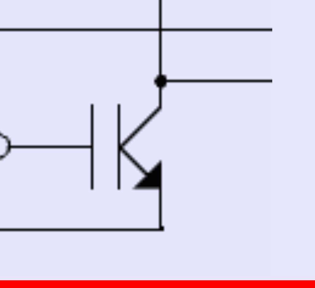
3 Three-phase Inverter BE1M14DEP 3 3
4 Scalar Control Properties (U/f Method) Disadvantages of scalar (U/f) control: Very low dynamics Changes in the asynchronous machine take place at the speed given by the rotor time constant (ie, up to seconds on large machines) The input is the frequency - it is not possible to directly control of IM torque Not suitable for traction The motor torque is dependent on the slip frequency - it is still the same (the percentage with the lower output frequency of the drive increases) Advantages of scalar (U / f:) control: Simplicity of management (especially development) BE1M14DEP 4 4
5 Scalar Control - U/f Method) Scalar control: Only one variable, mostly frequency, is controlled. Voltage is tied to frequency, so the name "U / f" Voltage Rated voltage Rated speed Speed [1/min] I 1 IM B1M14DEP BE1M14DEP 5 5
6 PWM Generation hw Support Carrier Wave Code (Kód nosné vlny) Žádost o obsluhu Int Clock (Takt) Prescaler (Předdělička) Up-Down Counter (Obousměrný čítač) + Comparator (Komparátor ) Dead Time & Output Logic Modulation Wave Value (Kód modulačního průběhu ) CR Compare Register (Porovnávaná hodnota ) Program Generování mrtvých dob a výstupní logika B1M14DEP BE1M14DEP 6 6
7 PWM Generation (One possible option) +1 Modulation Wave (Modulační průběh) Carrier Wave (Nosná vlna) 0-1 Interrupt Request (Žádost o obsluhu) + PWM Output (Výstup PWM) PWM Output (Výstup PWM) Time B1M14DEP BE1M14DEP 7 7
8 Vector Control Advantages of vector control versus scalar: Unmatched higher dynamics Working from zero revolutions (for some types of vector control including standing rotor) The drive input is a torque requirement (gas lever) Fit for traction The induction motor current is fully controlled Possibility of short-term overload and work with a higher torque than the maximum torque point To switch from scalar to vector control, in most cases, only software change is sufficient B1M14DEP BE1M14DEP 8 8
9 Torque is related to currents Control Dymamics Torque of any electric machine current Dynamics of electric machine fast current changes Rapid changes in currents require a voltage (the winding of the machine is inductive) In order to increase the dynamics, it is necessary to directly control the currents (for induction motor with the short-circuit armature only stator currents are possible to control), which can not be done by the U / f control B1M14DEP BE1M14DEP 9 9
10 Vector Control Vector control: Two quantities of the induction machine are controlled separately Mostly, this is a stator current divided into two components: Current component affecting the magnetic flux Current component affecting the torque IM machine DC machine I 1 IM I M I Ψ IM = B1M14DEP BE1M14DEP 10 10
11 Space Vector Idea The space vector I 1 can express the effect of all currents flowing through all phases of the electric machine stator Symmetrical winding is assumed for a three-phase, two-pole machine (the angle of rotation is 120 ) The expression can be modified provided the center point is not connected (i.e. i a +i b +i c = 0) and after modifiying e j120 a e j240 i =R I = 3 2 K i a I=K i a i b e j 120 i c e j 240 I=K 3 2 i a j 3 2 i a 2i b i =I I = 3 2 K i bi c = 3 2 K i a 2 i b BE1M14DEP 11 11
12 Space Vector Idea The space vector I 1 can express the effect of all currents flowing through all phases of the electric machine stator Symmetrical winding is assumed for a three-phase, two-pole machine (the angle of rotation is 120 ) I=K i a i b e j 120 i c e j 240 The expression can be modified provided the center point is not connected (i.e. i a +i b +i c = 0) and after modifiying e j120 a e j240 i =R I = 3 2 K i a Při vhodné volbě K I=K 3 2 i a i α j = i a 3 2 i a 2i b i =I I = 3 2 K i bi c = 3 2 K i a 2 i b BE1M14DEP 12 12
13 Clark Transformation Three phases of the machine Two axis i a i α i β i c i b Clark's transformation converts the three phases (a, b, c) into two phases (α, β) For K = 2/3 Clark's transformation is expressed as: i α =i a i β = 3 3 (i a+2i b ) BE1M14DEP 13 13
14 Rotation of Coordinates I 1 I k Space vector I in the coordinate system tied to the stator Space vector I in coordinate system k I k = I 1 e j k Where θ k is the angle of rotation of the coordinate system k If the coordinate system (k, l) is rotated by the angle θ k against (α, β): i k =i α cosθ k +i β sinθ k i l =i α sinθ k +i β cosθ k B1M14DEP BE1M14DEP 14 14
15 Park Transfomation α θ d β ω 1 q i d =i cos i sin i q =i sin i cos BE1M14DEP 15 15
16 Used Coordinate Systems Coordinates Designation Rotation speed Coordinates tied to the stator 0 Coordinates tied to the rotor k, l ω Coordinates tied to the magnetic flux of the rotor d, q ω 1 BE1M14DEP
17 Induction Motor Torque Pro K= 2 3 P= 3 2 U 1 I 1 cos = 3 2 R U 1 I 1 BE1M14DEP 17 17
18 Induction Motor Torque For K= 2 3 P= 3 2 U 1 I 1 cos = 3 2 R U 1 I 1 Voltage equation of induction motor stator winding written by space vectors: 1 U 1 =R 1 I 1 d dt =R 1 I 1 j 1 1 BE1M14DEP 18 18
19 Induction Motor Torque Pro K= 2 3 P= 3 2 U 1 I 1 cos = 3 2 R U 1 I 1 P= 3 2 [ R 1 i 2 2 i i 1 1 i 1 ] BE1M14DEP 19 19
20 Induction Motor Torque Pro K= 2 3 P= 3 2 U 1 I 1 cos = 3 2 R U 1 I 1 P= 3 2 [ R 1 i 2 2 i i 1 1 i 1 ] Power dissipation in resistance: P=R I 2 =R i a 2 i b 2 BE1M14DEP 20 20
21 Induction Motor Torque Pro K= 2 3 P= 3 2 U 1 I 1 cos = 3 2 R U 1 I 1 P= 3 2 [ R 1 i 2 2 i i 1 1 i 1 ] Losses in the stator P=R I 2 =R i a 2 i b 2 BE1M14DEP 21 21
22 Induction Motor Torque Pro K= 2 3 P= 3 2 U 1 I 1 cos = 3 2 R U 1 I 1 P= 3 2 [ R 1 i 2 2 i i 1 1 i 1 ] Losses in the stator Power transmitted by air gap from the stator to the rotor BE1M14DEP 22 22


23 Induction Motor Torque Pro K= 2 3 P= 3 2 U 1 I 1 cos = 3 2 R U 1 I 1 BE1M14DEP 23 23


24 Induction Motor Torque Pro K= 2 3 P= 3 2 U 1 I 1 cos = 3 2 R U 1 I 1 1s = 1 p p BE1M14DEP 24 24


25 Induction Motor Torque Pro K= 2 3 P= 3 2 U 1 I 1 cos = 3 2 R U 1 I 1 BE1M14DEP 25 25
26 Induction Motor Torque M i = 3 2 p p c A B sin sin γ is the angle between the vectors A a B A B c I 1 I 1 I 1 I 1 I 2 I 2 I 2 Ψ 1 I 2 Ψ 1 Ψ µ Ψ 2 Ψ 1 Ψ µ Ψ 2 Ψ 2 L h L h / L 2 L h / L 1 L h / σl 1 L 2 M i = 3 2 p p 1 i 1 1 i 1 BE1M14DEP
27 Induction Motor Torque M i = 3 2 p p c A B sin sin γ is the angle between the vectors A a B A B c I 1 I 1 I 1 I 1 I 2 I 2 I 2 Ψ 1 I 2 Ψ 1 Ψ µ Ψ 2 Ψ 1 Ψ µ Ψ 2 Ψ 2 L h L h / L 2 L h / L 1 L h / σl 1 L 2 M i = 3 2 p p 2 d i 1 q 2 q i 1 d L h L 2 M i = 3 2 p p 1 i 1 1 i 1 BE1M14DEP
28 Stator Current Components M i = 3 2 p p 2 d i 1 q 2 q i 1 d L h L 2 BE1M14DEP 28 28
29 Stator Current Components M i = 3 2 p p 2 d i 1 q 2 q i 1 d L h L 2 Ψ 2q is equal to zero because the (d, q) axis direction is given just by the direction of Ψ 2 M i = 3 2 p p 2 i 1 q L h L 2 BE1M14DEP 29 29
30 Stator Current Components M i = 3 2 p p 2 d i 1 q 2 q i 1 d L h L 2 Ψ 2q is equal to zero because the (d, q) axis direction is given just by the direction of Ψ 2 M i = 3 2 p p 2 i 1 q L h L 2 M i 2 Ψ 2 is excitation stator current component which affect the torque BE1M14DEP 30 30
31 Stator Current Components M i = 3 2 p p 2 d i 1 q 2 q i 1 d L h L 2 Ψ 2q is equal to zero because the (d, q) axis direction is given just by the direction of Ψ 2 M i = 3 2 p p 2 i 1 q L h M i 2 L 2 Ψ 2 is excitation stator current component which affects the torque d 2d dt = R 2 L 2 L h 2d => 2 L h stator current component which affects magnetic flux BE1M14DEP
32 IM versus DC machine The stator current of the three-phase induction short-circuit machine has two stages of freedom (the third one is deleted because center of windings is drawn outside) and can be divided into two components that correspond to the armature current and the excitation of the DC motor. It is therefore possible to control independetly the torque and the excitation of induction machine. IM machine DC machine AM i a i b i a i b BE1M14DEP 32 32
33 Voltage Vector Control of an Induction Machine * * PI PI u 1d u 1q d,q θ u 1α u 1β a,b,c u 1a,b,c Inverter i a,i b,(i c ) IM IM Model d,q i α a,b,c ω 2 θ r θ i β θ IRC n IRC Decoder BE1M14DEP 33 33
34 Voltage Vector Control of an Induction Machine * * Clark Transformation u i 1d =i a i = 3 PI PI u 1q θ u 1α d,q 3 i a 2i b a,b,c u 1β u 1a,b,c Inverter i a,i b,(i c ) IM IM Model ω 2 θ r d,q θ i α i β a,b,c θ IRC n IRC Decoder BE1M14DEP
35 Voltage Vector Control of an Induction Machine * * Park Transformation PI PI i d =i cos i sin u 1d u 1q d,q θ u 1α u 1β a,b,c u 1a,b,c i q =i sin i cos střídač i a,i b,(i c ) AM IM Model ω 2 θ r d,q θ i α i β a,b,c θ IRC n IRC Decoder BE1M14DEP
36 Voltage Vector Control of an Induction Machine Induction machine I 1 -n model * * d Ψ 2 dt u 1d PI d,q střídač AM PI (L a,b,c Lu h Ψ u 1q 1β 2 ) ω 2 = L h R 2 2 L θ 2 i a,i b,(i c ) = R 2 u 1α u 1a,b,c Ψ 2 IM Model ω 2 θ r d,q θ i α i β a,b,c θ IRC n IRC Decoder B1M14DEP 36 36
37 Voltage Vector Control of an Induction Machine Induction machine I 1 -n model * * d 2 dt u 1d PI d,q střídač AM PI L a,b,c Lu h u 1q 1β 2 2 = L h R 2 2 L θ 2 i a,i b,(i c ) = R 2 u 1α u 1a,b,c 2 IM Model ω 2 θ r d,q θ i α i β a,b,c θ IRC n IRC Decoder BE1M14DEP 37 37
38 Voltage Vector Control of an Induction Machine * Induction machine I 1 -n model after suitable substitution is used i 2 = 2 * d i 2 dt PI u 1d L d,q h střídač u u a,b,c 1q i L 1d i 1β 2 2 = R 2 2 PI = R 2 θ u 1α u 1a,b,c AM L 2 i 2 i a,i b,(i c ) IM Model ω 2 θ r d,q θ i α i β a,b,c θ IRC n IRC Decoder BE1M14DEP 38 38
39 Voltage Vector Control of an Induction Machine * PI Slip frequency integrator PI * IM Model ω 2 θ r u 1d u 1q d,q d,q θ θ u 1α u 1β a,b,c i α i β u 1a,b,c střídač r = 2 dt a,b,c AM i a,i b,(i c ) θ IRC n IRC Decoder BE1M14DEP
40 Voltage Vector Control of an Induction Machine * PI d,q The IRC sensor decoder PI u u a,b,c number 1q of pulses 1β θ IRC = θ pulses per rotation p p 2 * IM Model ω 2 θ r u 1d d,q θ u 1α i α i β u 1a,b,c střídač a,b,c IM i a,i b,(i c ) θ IRC n IRC Decoder BE1M14DEP
41 Voltage Vector Control of an Induction Machine * * IM Model ω 2 PI PI θ r u 1d u 1q d,q θ θ r 2 u 1α 1 střídač a,b,c u 1β i β u 1a,b,c IRC Slip frequency 2 = 1 r IRC = i d,q α a,b,c Feeding frequency of machine AM El. angle speed of shaft i a,i b,(i c ) θ IRC n IRC Decoder BE1M14DEP
42 Voltage Vector Control of an Induction Machine * * PI PI u 1d u 1q d,q θ u 1α u 1β a,b,c u 1a,b,c Inverter i a,i b,(i c ) i IM d,q α a,b,c PI Model controllers regulate i each component i of the current separately 1q θ β Both components are DC (does not change with ω, ω 1 or ω 2 ) ω 2 The input to the θ controllers are the error values of the currents. The outputs are a r voltage requirements. u t =k p e t k i e t dt IM θ IRC n dekodér IRC BE1M14DEP
43 Voltage Vector Control of an Induction Machine * * model AM PI PI θ r u 1d u 1q d,q u 1α u 1β a,b,c u 1a,b,c Inverse Park and Clark transformations i u d,q α =u d cos u q sin u =u d sin u q cos ω 2 Inverse: sins have inverse signs θ i β Inverter i a,i b,(i c ) IM u a =u a,b,c u b = 1 2 u 3 2 u θ IRC u c = 1 2 u 3 n2 u dekodér IRC B1M14DEP 43 43


44 Voltage Vector Control of an Induction Machine BE1M14DEP 44 44
45 Three-phase Inverter BE1M14DEP 45 45
46 Space Vector Modulation Each of the three branches of the voltage converter always has only one of two transistor switched on. For the three branches it is 2 3 = 8 different states altogether. a b c Ua-b Ub-c Ua-c výstup nic U DC 0 -U DC U DC -U DC U DC +U DC U DC 0 +U DC U DC +U DC U DC -U DC nic BE1M14DEP 46 46
47 Space Vector Modulation BE1M14DEP 47 47

48 Space Vector Modulation BE1M14DEP 48 48
49 Six available active states at the output of the inverter Space Vector Modulation b U180 U120 U240 U60 U0 U300 a c BE1M14DEP 49 49
50 Space Vector Modulation To achieve a certain output should be combined over time several output vectors, including zero vector. There are many ways, how to draw a vector which differ in accuracy, computational difficulty and switching losses. However, the outputs always have character PWM modulation. b U0 U60 a The simplest method is: PWM x = u x 2U max 0.5 x {a,b, c} c BE1M14DEP 50 50
51 Space Vector Modulation BE1M14DEP 51 51
52 Space Vector Modulation 52 BE1M14DEP 52
53 Digital Control of Electric Drives Induction Motor Vector Control End BE1M14DEP 53 53
Chapter 5 Three phase induction machine (1) Shengnan Li
 Shengnan Li") Chapter 5 Three phase induction machine (1) Shengnan Li Main content Structure of three phase induction motor Operating principle of three phase induction motor Rotating magnetic field Graphical representation
Chapter 5 Three phase induction machine (1) Shengnan Li Main content Structure of three phase induction motor Operating principle of three phase induction motor Rotating magnetic field Graphical representation
Lesson 17: Synchronous Machines
 Lesson 17: Synchronous Machines ET 332b Ac Motors, Generators and Power Systems Lesson 17_et332b.pptx 1 Learning Objectives After this presentation you will be able to: Explain how synchronous machines
JRE SCHOOL OF Engineering
 JRE SCHOOL OF Engineering Class Test-1 Examinations September 2014 Subject Name Electromechanical Energy Conversion-II Subject Code EEE -501 Roll No. of Student Max Marks 30 Marks Max Duration 1 hour Date
International Journal of Advance Engineering and Research Development SIMULATION OF FIELD ORIENTED CONTROL OF PERMANENT MAGNET SYNCHRONOUS MOTOR
 Scientific Journal of Impact Factor(SJIF): 3.134 e-issn(o): 2348-4470 p-issn(p): 2348-6406 International Journal of Advance Engineering and Research Development Volume 2,Issue 4, April -2015 SIMULATION
Modelling of Closed Loop Speed Control for Pmsm Drive
 Modelling of Closed Loop Speed Control for Pmsm Drive Vikram S. Sathe, Shankar S. Vanamane M. Tech Student, Department of Electrical Engg, Walchand College of Engineering, Sangli. Associate Prof, Department
Mathematical Modelling of Permanent Magnet Synchronous Motor with Rotor Frame of Reference
 Mathematical Modelling of Permanent Magnet Synchronous Motor with Rotor Frame of Reference Mukesh C Chauhan 1, Hitesh R Khunt 2 1 P.G Student (Electrical),2 Electrical Department, AITS, rajkot 1 mcchauhan1@aits.edu.in
Introduction to Synchronous. Machines. Kevin Gaughan
 Introduction to Synchronous Machines Kevin Gaughan The Synchronous Machine An AC machine (generator or motor) with a stator winding (usually 3 phase) generating a rotating magnetic field and a rotor carrying
Lecture 8: Sensorless Synchronous Motor Drives
 1 / 22 Lecture 8: Sensorless Synchronous Motor Drives ELEC-E8402 Control of Electric Drives and Power Converters (5 ECTS) Marko Hinkkanen Spring 2017 2 / 22 Learning Outcomes After this lecture and exercises
3 d Calculate the product of the motor constant and the pole flux KΦ in this operating point. 2 e Calculate the torque.
 Exam Electrical Machines and Drives (ET4117) 11 November 011 from 14.00 to 17.00. This exam consists of 5 problems on 4 pages. Page 5 can be used to answer problem 4 question b. The number before a question
Massachusetts Institute of Technology Department of Electrical Engineering and Computer Science Electric Machines
 Massachusetts Institute of Technology Department of Electrical Engineering and Computer Science 6.685 Electric Machines Problem Set 10 Issued November 11, 2013 Due November 20, 2013 Problem 1: Permanent
Dynamic Modeling of Surface Mounted Permanent Synchronous Motor for Servo motor application
 797 Dynamic Modeling of Surface Mounted Permanent Synchronous Motor for Servo motor application Ritu Tak 1, Sudhir Y Kumar 2, B.S.Rajpurohit 3 1,2 Electrical Engineering, Mody University of Science & Technology,
CHAPTER 2 MODELLING OF INTERIOR PERMANENT MAGNET SYNCHRONOUS MOTOR
 21 CHAPTER 2 MODELLING OF INTERIOR PERMANENT MAGNET SYNCHRONOUS MOTOR 2.1 INTRODUCTION The need for adjustable speed drives in industrial applications has been increasing progressively. The variable speed
Comparative Analysis of Speed Control of Induction Motor by DTC over Scalar Control Technique
 Comparative Analysis of Speed Control of Induction Motor by DTC over Scalar Control Technique S.Anuradha 1, N.Amarnadh Reddy 2 M.Tech (PE), Dept. of EEE, VNRVJIET, T.S, India 1 Assistant Professor, Dept.
Mathematical Modeling and Dynamic Simulation of a Class of Drive Systems with Permanent Magnet Synchronous Motors
 Applied and Computational Mechanics 3 (2009) 331 338 Mathematical Modeling and Dynamic Simulation of a Class of Drive Systems with Permanent Magnet Synchronous Motors M. Mikhov a, a Faculty of Automatics,
2016 Kappa Electronics Motor Control Training Series Kappa Electronics LLC. -V th. Dave Wilson Co-Owner Kappa Electronics.
 2016 Kappa Electronics Motor Control Training Series 2016 Kappa Electronics C V th CoOwner Kappa Electronics www.kappaiq.com Benefits of Field Oriented Control NewtonMeters Maximum Torque Per Amp (MTPA)
Electric Machines I Three Phase Induction Motor. Dr. Firas Obeidat
 Electric Machines I Three Phase Induction Motor Dr. Firas Obeidat 1 Table of contents 1 General Principles 2 Construction 3 Production of Rotating Field 4 Why Does the Rotor Rotate 5 The Slip and Rotor
Lecture 9: Space-Vector Models
 1 / 30 Lecture 9: Space-Vector Models ELEC-E8405 Electric Drives (5 ECTS) Marko Hinkkanen Autumn 2017 2 / 30 Learning Outcomes After this lecture and exercises you will be able to: Include the number of
A new FOC technique based on predictive current control for PMSM drive
 ISSN 1 746-7, England, UK World Journal of Modelling and Simulation Vol. 5 (009) No. 4, pp. 87-94 A new FOC technique based on predictive current control for PMSM drive F. Heydari, A. Sheikholeslami, K.
Control of Wind Turbine Generators. James Cale Guest Lecturer EE 566, Fall Semester 2014 Colorado State University
 Control of Wind Turbine Generators James Cale Guest Lecturer EE 566, Fall Semester 2014 Colorado State University Review from Day 1 Review Last time, we started with basic concepts from physics such as
DC motors. 1. Parallel (shunt) excited DC motor
 excited DC motor") DC motors 1. Parallel (shunt) excited DC motor A shunt excited DC motor s terminal voltage is 500 V. The armature resistance is 0,5 Ω, field resistance is 250 Ω. On a certain load it takes 20 A current
DC motors 1. Parallel (shunt) excited DC motor A shunt excited DC motor s terminal voltage is 500 V. The armature resistance is 0,5 Ω, field resistance is 250 Ω. On a certain load it takes 20 A current
Synchronous Machines
 Synchronous Machines Synchronous Machines n 1 Φ f n 1 Φ f I f I f I f damper (run-up) winding Stator: similar to induction (asynchronous) machine ( 3 phase windings that forms a rotational circular magnetic
Design and implementation of a sliding-mode observer of the rotor flux and rotor speed in induction machines
 1 Design and implementation of a sliding-mode observer of the rotor flux and rotor speed in induction machines João Ferraz, Paulo Branco Phd. Abstract A sliding-mode observer for the rotor flux and speed
Control of an Induction Motor Drive
 Control of an Induction Motor Drive 1 Introduction This assignment deals with control of an induction motor drive. First, scalar control (or Volts-per-Hertz control) is studied in Section 2, where also
Permanent Magnet Synchronous Motors (PMSM). Parameters influence on the synchronization process of a PMSM
. Parameters influence on the synchronization process of a PMSM") Permanent Magnet ynchronous Motors (PMM). Parameters influence on the synchronization process of a PMM J. ais, M. P. Donsión Department of Electromechanics and Power Electronics Faculty of electrical engineering
Permanent Magnet ynchronous Motors (PMM). Parameters influence on the synchronization process of a PMM J. ais, M. P. Donsión Department of Electromechanics and Power Electronics Faculty of electrical engineering
Revision Guide for Chapter 15
 Revision Guide for Chapter 15 Contents tudent s Checklist Revision otes Transformer... 4 Electromagnetic induction... 4 Generator... 5 Electric motor... 6 Magnetic field... 8 Magnetic flux... 9 Force on
ELECTRICALMACHINES-I QUESTUION BANK
 ELECTRICALMACHINES-I QUESTUION BANK UNIT-I INTRODUCTION OF MAGNETIC MATERIAL PART A 1. What are the three basic rotating Electric machines? 2. Name the three materials used in machine manufacture. 3. What
Lecture 7: Synchronous Motor Drives
 1 / 46 Lecture 7: Synchronous Motor Drives ELEC-E8402 Control of Electric Drives and Power Converters (5 ECTS) Marko Hinkkanen Spring 2017 2 / 46 Learning Outcomes After this lecture and exercises you
AC Induction Motor Stator Resistance Estimation Algorithm
 7th WSEAS International Conference on Electric Power Systems, High Voltages, Electric Machines, Venice, Italy, November 21-23, 27 86 AC Induction Motor Stator Resistance Estimation Algorithm PETR BLAHA
A Direct Torque Controlled Induction Motor with Variable Hysteresis Band
 UKSim 2009: th International Conference on Computer Modelling and Simulation A Direct Torque Controlled Induction Motor with Variable Hysteresis Band Kanungo Barada Mohanty Electrical Engineering Department,
Comparison Between Direct and Indirect Field Oriented Control of Induction Motor
 Comparison Between Direct and Indirect Field Oriented Control of Induction Motor Venu Gopal B T Research Scholar, Department of Electrical Engineering UVCE, Bangalore University, Bengaluru ABSTRACT - Vector
Lecture 1: Induction Motor
 1 / 22 Lecture 1: Induction Motor ELEC-E8402 Control of Electric Drives and Power Converters (5 ECTS) Marko Hinkkanen Aalto University School of Electrical Engineering Spring 2016 2 / 22 Learning Outcomes
Modeling Free Acceleration of a Salient Synchronous Machine Using Two-Axis Theory
 1 Modeling ree Acceleration of a Salient Synchronous Machine Using Two-Axis Theory Abdullah H. Akca and Lingling an, Senior Member, IEEE Abstract This paper investigates a nonlinear simulation model of
Chapter 4. Synchronous Generators. Basic Topology
 Basic Topology Chapter 4 ynchronous Generators In stator, a three-phase winding similar to the one described in chapter 4. ince the main voltage is induced in this winding, it is also called armature winding.
DIRECT TORQUE CONTROL OF PERMANENT MAGNET SYNCHRONOUS MOTOR USING TWO LEVEL INVERTER- SURVEY PAPER
 DIRECT TORQUE CONTROL OF PERMANENT MAGNET SYNCHRONOUS MOTOR USING TWO LEVEL INVERTER- SURVEY PAPER 1 PREETI SINGH, BHUPAL SINGH 1 M.Tech (scholar) Electrical Power & Energy System, lecturer Ajay Kumar
Step Motor Modeling. Step Motor Modeling K. Craig 1
 Step Motor Modeling Step Motor Modeling K. Craig 1 Stepper Motor Models Under steady operation at low speeds, we usually do not need to differentiate between VR motors and PM motors (a hybrid motor is
EFFICIENCY OPTIMIZATION OF VECTOR-CONTROLLED INDUCTION MOTOR DRIVE
 EFFICIENCY OPTIMIZATION OF VECTOR-CONTROLLED INDUCTION MOTOR DRIVE Hussein Sarhan Department of Mechatronics Engineering, Faculty of Engineering Technology, Amman, Jordan ABSTRACT This paper presents a
3-Phase PMSM FOC Control
 3-Phase PMSM FOC Control 32-BIT MICROCONTROLLER FM3 Family APPLICATION NOTE Publication Number FM3_AN709-00015 Revision 1.0 Issue Date Feb 26, 2015 2 FM3_ AN709-00015-1v0-E, Feb 26, 2015 Target products
Performance analysis of variable speed multiphase induction motor with pole phase modulation
 ARCHIVES OF ELECTRICAL ENGINEERING VOL. 65(3), pp. 425-436 (2016) DOI 10.1515/aee-2016-0031 Performance analysis of variable speed multiphase induction motor with pole phase modulation HUIJUAN LIU, JUN
Sensorless DTC-SVM of Induction Motor by Applying Two Neural Controllers
 Sensorless DTC-SVM of Induction Motor by Applying Two Neural Controllers Abdallah Farahat Mahmoud Dept. of Electrical Engineering, Al-Azhar University, Qena, Egypt engabdallah2012@azhar.edu.eg Adel S.
Behaviour of synchronous machine during a short-circuit (a simple example of electromagnetic transients)
") ELEC0047 - Power system dynamics, control and stability (a simple example of electromagnetic transients) Thierry Van Cutsem t.vancutsem@ulg.ac.be www.montefiore.ulg.ac.be/~vct October 2018 1 / 25 Objectives
ELEC0047 - Power system dynamics, control and stability (a simple example of electromagnetic transients) Thierry Van Cutsem t.vancutsem@ulg.ac.be www.montefiore.ulg.ac.be/~vct October 2018 1 / 25 Objectives
The Control of a Continuously Operated Pole-Changing Induction Machine
 The Control of a Continuously Operated PoleChanging Induction Machine J.W. Kelly Electrical and Computer Engineering Michigan State University East Lansing, MI 48824 28 February 2002 MD Lab 1/0202 1 Outline
University of Jordan Faculty of Engineering & Technology Electric Power Engineering Department
 University of Jordan Faculty of Engineering & Technology Electric Power Engineering Department EE471: Electrical Machines-II Tutorial # 2: 3-ph Induction Motor/Generator Question #1 A 100 hp, 60-Hz, three-phase
the machine makes analytic calculation of rotor position impossible for a given flux linkage and current value.
 COMPARISON OF FLUX LINKAGE ESTIMATORS IN POSITION SENSORLESS SWITCHED RELUCTANCE MOTOR DRIVES Erkan Mese Kocaeli University / Technical Education Faculty zmit/kocaeli-turkey email: emese@kou.edu.tr ABSTRACT
An Introduction to Electrical Machines. P. Di Barba, University of Pavia, Italy
 An Introduction to Electrical Machines P. Di Barba, University of Pavia, Italy Academic year 0-0 Contents Transformer. An overview of the device. Principle of operation of a single-phase transformer 3.
Three phase induction motor using direct torque control by Matlab Simulink
 Three phase induction motor using direct torque control by Matlab Simulink Arun Kumar Yadav 1, Dr. Vinod Kumar Singh 2 1 Reaserch Scholor SVU Gajraula Amroha, U.P. 2 Assistant professor ABSTRACT Induction
Electrical Machines and Energy Systems: Operating Principles (Part 2) SYED A Rizvi
 SYED A Rizvi") Electrical Machines and Energy Systems: Operating Principles (Part 2) SYED A Rizvi AC Machines Operating Principles: Synchronous Motor In synchronous motors, the stator of the motor has a rotating magnetic
Electrical Machines and Energy Systems: Operating Principles (Part 2) SYED A Rizvi AC Machines Operating Principles: Synchronous Motor In synchronous motors, the stator of the motor has a rotating magnetic
Generators for wind power conversion
 Generators for wind power conversion B. G. Fernandes Department of Electrical Engineering Indian Institute of Technology, Bombay Email : bgf@ee.iitb.ac.in Outline of The Talk Introduction Constant speed
Digitization of Vector Control Algorithm Using FPGA
 Digitization of Vector Control Algorithm Using FPGA M. P. Priyadarshini[AP] 1, K. G. Dharani[AP] 2, D. Kavitha[AP] 3 DEPARTMENT OF ECE, MVJ COLLEGE OF ENGINEERING, BANGALORE Abstract: The paper is concerned
Synergetic Control for Electromechanical Systems
 Synergetic Control for Electromechanical Systems Anatoly A. Kolesnikov, Roger Dougal, Guennady E. Veselov, Andrey N. Popov, Alexander A. Kolesnikov Taganrog State University of Radio-Engineering Automatic
Definition Application of electrical machines Electromagnetism: review Analogies between electric and magnetic circuits Faraday s Law Electromagnetic
 Definition Application of electrical machines Electromagnetism: review Analogies between electric and magnetic circuits Faraday s Law Electromagnetic Force Motor action Generator action Types and parts
Steady State Modeling of Doubly Fed Induction Generator
 Steady State Modeling of Douly Fed Induction Generator Bhola Jha 1, Dr. K. R. M Rao 2 1 Dept. of Electrical Engg., G. B. Pant Engg. College, Pauri-Garhwal, India 2 Dept. of Electrical Engg., M. J. College
An adaptive sliding mode control scheme for induction motor drives
 An adaptive sliding mode control scheme for induction motor drives Oscar Barambones, Patxi Alkorta, Aitor J. Garrido, I. Garrido and F.J. Maseda ABSTRACT An adaptive sliding-mode control system, which
Equal Pitch and Unequal Pitch:
 Equal Pitch and Unequal Pitch: Equal-Pitch Multiple-Stack Stepper: For each rotor stack, there is a toothed stator segment around it, whose pitch angle is identical to that of the rotor (θs = θr). A stator
MCE380: Measurements and Instrumentation Lab. Chapter 5: Electromechanical Transducers
 MCE380: Measurements and Instrumentation Lab Chapter 5: Electromechanical Transducers Part I Topics: Transducers and Impedance Magnetic Electromechanical Coupling Reference: Holman, CH 4. Cleveland State
Automatic Control Systems. -Lecture Note 15-
 -Lecture Note 15- Modeling of Physical Systems 5 1/52 AC Motors AC Motors Classification i) Induction Motor (Asynchronous Motor) ii) Synchronous Motor 2/52 Advantages of AC Motors i) Cost-effective ii)
د شوقي حامد عرفه ابراهيم
 2015 /1/19 اإلجابة النموذجية لمادة نظم التشغيل الكهربية ك 563 د شوقي حامد عرفه ابراهيم يوم االثنين الموافق Benha University Benha Faculty of Engineering Subject: Electrical drives (E563) Time: 3hours Fifth
PERFORMANCE ANALYSIS OF DIRECT TORQUE CONTROL OF 3-PHASE INDUCTION MOTOR
 PERFORMANCE ANALYSIS OF DIRECT TORQUE CONTROL OF 3-PHASE INDUCTION MOTOR 1 A.PANDIAN, 2 Dr.R.DHANASEKARAN 1 Associate Professor., Department of Electrical and Electronics Engineering, Angel College of
Nonlinear Electrical FEA Simulation of 1MW High Power. Synchronous Generator System
 Nonlinear Electrical FEA Simulation of 1MW High Power Synchronous Generator System Jie Chen Jay G Vaidya Electrodynamics Associates, Inc. 409 Eastbridge Drive, Oviedo, FL 32765 Shaohua Lin Thomas Wu ABSTRACT
PESIT Bangalore South Campus Hosur road, 1km before Electronic City, Bengaluru -100 Department of Electronics & Communication Engineering
 QUESTION PAPER INTERNAL ASSESSMENT TEST 2 Date : /10/2016 Marks: 0 Subject & Code: BASIC ELECTRICAL ENGINEERING -15ELE15 Sec : F,G,H,I,J,K Name of faculty : Dhanashree Bhate, Hema B, Prashanth V Time :
Doubly salient reluctance machine or, as it is also called, switched reluctance machine. [Pyrhönen et al 2008]
![Doubly salient reluctance machine or, as it is also called, switched reluctance machine. [Pyrhönen et al 2008]](/thumbs/86/93665357.jpg "Doubly salient reluctance machine or, as it is also called, switched reluctance machine. [Pyrhönen et al 2008]") Doubly salient reluctance machine or, as it is also called, switched reluctance machine [Pyrhönen et al 2008] Pros and contras of a switched reluctance machine Advantages Simple robust rotor with a small
Doubly salient reluctance machine or, as it is also called, switched reluctance machine [Pyrhönen et al 2008] Pros and contras of a switched reluctance machine Advantages Simple robust rotor with a small
Speed Sensorless Control of a Long-Stator Linear Synchronous-Motor arranged by Multiple Sections
 Speed Sensorless Control of a Long-Stator Linear Synchronous-Motor arranged by Multiple Sections Roberto Leidhold Peter Mutschler Department of Power Electronics and Control of Drives Darmsta University
Transient Analysis of Three Phase Squirrel Cage Induction Machine using Matlab
 Transient Analysis of Three Phase Squirrel Cage Induction Machine using Matlab Mukesh Kumar Arya*, Dr.Sulochana Wadhwani** *( Department of Electrical Engineering, Madhav Institute of Technology & Science,
DEVELOPMENT OF DIRECT TORQUE CONTROL MODELWITH USING SVI FOR THREE PHASE INDUCTION MOTOR
 DEVELOPMENT OF DIRECT TORQUE CONTROL MODELWITH USING SVI FOR THREE PHASE INDUCTION MOTOR MUKESH KUMAR ARYA * Electrical Engg. Department, Madhav Institute of Technology & Science, Gwalior, Gwalior, 474005,
PRINCIPLE OF DESIGN OF FOUR PHASE LOW POWER SWITCHED RELUCTANCE MACHINE AIMED TO THE MAXIMUM TORQUE PRODUCTION
 Journal of ELECTRICAL ENGINEERING, VOL. 55, NO. 5-6, 24, 138 143 PRINCIPLE OF DESIGN OF FOUR PHASE LOW POWER SWITCHED RELUCTANCE MACHINE AIMED TO THE MAXIMUM TORQUE PRODUCTION Martin Lipták This paper
A Novel Three-phase Matrix Converter Based Induction Motor Drive Using Power Factor Control
 Australian Journal of Basic and Applied Sciences, 8(4) Special 214, Pages: 49-417 AENSI Journals Australian Journal of Basic and Applied Sciences ISSN:1991-8178 Journal home page: www.ajbasweb.com A Novel
Research on the winding control system in winding vacuum coater
 Acta Technica 61, No. 4A/2016, 257 268 c 2017 Institute of Thermomechanics CAS, v.v.i. Research on the winding control system in winding vacuum coater Wenbing Jin 1, Suo Zhang 1, Yinni Jin 2 Abstract.
Research on Permanent Magnet Linear Synchronous Motor Control System Simulation *
 Available online at www.sciencedirect.com AASRI Procedia 3 (2012 ) 262 269 2012 AASRI Conference on Modeling, Identification and Control Research on Permanent Magnet Linear Synchronous Motor Control System
DESIGN AND MODELLING OF SENSORLESS VECTOR CONTROLLED INDUCTION MOTOR USING MODEL REFERENCE ADAPTIVE SYSTEMS
 DESIGN AND MODELLING OF SENSORLESS VECTOR CONTROLLED INDUCTION MOTOR USING MODEL REFERENCE ADAPTIVE SYSTEMS Janaki Pakalapati 1 Assistant Professor, Dept. of EEE, Avanthi Institute of Engineering and Technology,
Research on Control Method of Brushless DC Motor Based on Continuous Three-Phase Current
 6th International onference on Measurement, Instrumentation and Automation (IMIA 017 Research on ontrol Method of Brushless D Motor Based on ontinuous hree-phase urrent Li Ding 1,Mingliang Hu, Jun Zhao
Dynamic Modeling Of A Dual Winding Induction Motor Using Rotor Reference Frame
 American Journal of Engineering Research (AJER) e-issn: 2320-0847 p-issn : 2320-0936 Volume-7, Issue-11, pp-323-329 www.ajer.org Research Paper Open Access Dynamic Modeling Of A Dual Winding Induction
Independent Control of Speed and Torque in a Vector Controlled Induction Motor Drive using Predictive Current Controller and SVPWM
 Independent Control of Speed and Torque in a Vector Controlled Induction Motor Drive using Predictive Current Controller and SVPWM Vandana Peethambaran 1, Dr.R.Sankaran 2 Assistant Professor, Dept. of
Sensorless Speed Control for PMSM Based On the DTC Method with Adaptive System R. Balachandar 1, S. Vinoth kumar 2, C. Vignesh 3
 Sensorless Speed Control for PMSM Based On the DTC Method with Adaptive System R. Balachandar 1, S. Vinoth kumar 2, C. Vignesh 3 P.G Scholar, Sri Subramanya College of Engg & Tech, Palani, Tamilnadu, India
7. Transient stability
 1 7. Transient stability In AC power system, each generator is to keep phase relationship according to the relevant power flow, i.e. for a certain reactance X, the both terminal voltages V1and V2, and
Motor Info on the WWW Motorola Motors DC motor» /MOTORDCTUT.
 Motor Info on the WWW Motorola Motors DC motor» http://www.freescale.com/files/microcontrollers/doc/train_ref_material /MOTORDCTUT.html Brushless DC motor» http://www.freescale.com/files/microcontrollers/doc/train_ref_material
ENGG4420 LECTURE 7. CHAPTER 1 BY RADU MURESAN Page 1. September :29 PM
 CHAPTER 1 BY RADU MURESAN Page 1 ENGG4420 LECTURE 7 September 21 10 2:29 PM MODELS OF ELECTRIC CIRCUITS Electric circuits contain sources of electric voltage and current and other electronic elements such
Speed Sensor less Control and Estimation Based on Mars for Pmsm under Sudden Load Change
 International Journal of Engineering Inventions e-issn: 2278-7461, p-isbn: 2319-6491 Volume 2, Issue 3 (February 2013) PP: 77-86 Speed Sensor less Control and Estimation Based on Mars for Pmsm under Sudden
Mechatronics Engineering. Li Wen
 Mechatronics Engineering Li Wen Bio-inspired robot-dc motor drive Unstable system Mirko Kovac,EPFL Modeling and simulation of the control system Problems 1. Why we establish mathematical model of the control
SPEED CONTROL OF PMSM BY USING DSVM -DTC TECHNIQUE
 SPEED CONTROL OF PMSM BY USING DSVM -DTC TECHNIQUE J Sinivas Rao #1, S Chandra Sekhar *2, T Raghu #3 1 Asst Prof, Dept Of EEE, Anurag Engineering College, AP, INDIA 3 Asst Prof, Dept Of EEE, Anurag Engineering
CHAPTER 5 SIMULATION AND TEST SETUP FOR FAULT ANALYSIS
 47 CHAPTER 5 SIMULATION AND TEST SETUP FOR FAULT ANALYSIS 5.1 INTRODUCTION This chapter describes the simulation model and experimental set up used for the fault analysis. For the simulation set up, the
Vector Controlled Power Generation in a Point Absorber Based Wave Energy Conversion System
 Vector Controlled Power Generation in a Point Absorber Based Wave Energy Conversion System Jisha Thomas Chandy 1 and Mr. Vishnu J 2 1,2 Electrical & Electronics Dept of Engineering, Sree Buddha College
Unified Torque Expressions of AC Machines. Qian Wu
 Unified Torque Expressions of AC Machines Qian Wu Outline 1. Review of torque calculation methods. 2. Interaction between two magnetic fields. 3. Unified torque expression for AC machines. Permanent Magnet
Anakapalli Andhra Pradesh, India I. INTRODUCTION
 Robust MRAS Based Sensorless Rotor Speed Measurement of Induction Motor against Variations in Stator Resistance Using Combination of Back Emf and Reactive Power Methods Srikanth Mandarapu Pydah College
Stepping Motors. Chapter 11 L E L F L D
 Chapter 11 Stepping Motors In the synchronous motor, the combination of sinusoidally distributed windings and sinusoidally time varying current produces a smoothly rotating magnetic field. We can eliminate
Lezione 9 30 March. Scribes: Arianna Marangon, Matteo Vitturi, Riccardo Prota
 Control Laboratory: a.a. 2015/2016 Lezione 9 30 March Instructor: Luca Schenato Scribes: Arianna Marangon, Matteo Vitturi, Riccardo Prota What is left to do is how to design the low pass pole τ L for the
A New Predictive Control Strategy Dedicated to Salient Pole Synchronous Machines
 A New Predictive Control Strategy Dedicated to Salient Pole Synchronous Machines Nicolas Patin Member IEEE University of Technology of Compiègne Laboratoire d Electromécanique de Compiègne Rue Personne
Simulation of 3-Phase 2- Stator Induction Motor Using MATLAB Platform
 International Journal of Alied Engineering Research ISSN 0973-456 Volume 3, Number (08). 9437-944 Simulation of 3-Phase - Stator Induction Motor Using MATLAB Platform Pallavi R.Burande Deartment of Electrical
Sensorless Control of Two-phase Switched Reluctance Drive in the Whole Speed Range
 Sensorless Control of Two-phase Switched Reluctance Drive in the Whole Speed Range Dmitry Aliamkin, Alecksey Anuchin, Maxim Lashkevich Electric Drives Department of Moscow Power Engineering Institute,
Generators. What its all about
 Generators What its all about How do we make a generator? Synchronous Operation Rotor Magnetic Field Stator Magnetic Field Forces and Magnetic Fields Force Between Fields Motoring Generators & motors are
Novel DTC-SVM for an Adjustable Speed Sensorless Induction Motor Drive
 Novel DTC-SVM for an Adjustable Speed Sensorless Induction Motor Drive Nazeer Ahammad S1, Sadik Ahamad Khan2, Ravi Kumar Reddy P3, Prasanthi M4 1*Pursuing M.Tech in the field of Power Electronics 2*Working
Synchronous Machines
 Synchronous machine 1. Construction Generator Exciter View of a twopole round rotor generator and exciter. A Stator with laminated iron core C Slots with phase winding B A B Rotor with dc winding B N S
Power Quality Improvement in PMSM Drive Using Zeta Converter
 Power Quality Improvement in PMSM Drive Using Zeta Converter Y.Teja 1, A. DurgaPrasad 2, Sk. Chan Basha 3 1 PG Scholar, Dept of EEE, Sir CRR College of Engineering, Eluru, A.P. 2 Assistant Professor, Dept
Mini-project report. Modelling and control of a variablespeed subsea tidal turbine equipped with permanent magnet synchronous generator.
 1 Mini-project report Modelling and control of a variablespeed subsea tidal turbine equipped with permanent magnet synchronous generator. Shoan Mbabazi dtp09sm@sheffield.ac.uk August 2010 2 Modelling and
MATLAB SIMULATION OF DIRECT TORQUE CONTROL OF INDUCTION MOTOR USING CONVENTIONAL METHOD AND SPACE VECTOR PULSE WIDTH MODULATION
 MATLAB SIMULATION OF DIRECT TORQUE CONTROL OF INDUCTION MOTOR USING CONVENTIONAL METHOD AND SPACE VECTOR PULSE WIDTH MODULATION Naveen Chander Assistant Professor, Department of Electrical and Electronics
The Application of Anti-windup PI Controller, SIPIC on FOC of PMSM
 Electrical and Electronic Engineering 2016, 6(3): 39-48 DOI: 10.5923/j.eee.20160603.01 The Application of Anti-windup PI Controller, SIPIC on FOC of PMSM Hoo Choon Lih School of Engineering, Taylor s University,
Proceedings of the 6th WSEAS/IASME Int. Conf. on Electric Power Systems, High Voltages, Electric Machines, Tenerife, Spain, December 16-18,
 Proceedings of the 6th WSEAS/IASME Int. Conf. on Electric Power Systems, High Voltages, Electric Machines, Tenerife, Spain, December 16-18, 2006 196 A Method for the Modeling and Analysis of Permanent
International Journal of Advance Engineering and Research Development
 Scientific Journal of Impact Factor (SJIF): 4.7 International Journal of Advance Engineering and Research Development Volume 4, Issue 5, May-07 e-issn (O): 348-4470 p-issn (P): 348-6406 Mathematical modeling
MATLAB SIMULINK Based DQ Modeling and Dynamic Characteristics of Three Phase Self Excited Induction Generator
 628 Progress In Electromagnetics Research Symposium 2006, Cambridge, USA, March 26-29 MATLAB SIMULINK Based DQ Modeling and Dynamic Characteristics of Three Phase Self Excited Induction Generator A. Kishore,
Speed Control of PMSM Drives by Using Neural Network Controller
 Advance in Electronic and Electric Engineering. ISSN 2231-1297, Volume 4, Number 4 (2014), pp. 353-360 Research India Publications http://www.ripublication.com/aeee.htm Speed Control of PMSM Drives by
EC T32 - ELECTRICAL ENGINEERING
 EC T32 - ELECTRICAL ENGINEERING UNIT-I - TRANSFORMER 1. What is a transformer? 2. Briefly explain the principle of operation of transformers. 3. What are the parts of a transformer? 4. What are the types
Electrical Machines and Energy Systems: Operating Principles (Part 1) SYED A Rizvi
 SYED A Rizvi") Electrical Machines and Energy Systems: Operating Principles (Part 1) SYED A Rizvi AC Machines Operating Principles: Rotating Magnetic Field The key to the functioning of AC machines is the rotating magnetic
Electrical Machines and Energy Systems: Operating Principles (Part 1) SYED A Rizvi AC Machines Operating Principles: Rotating Magnetic Field The key to the functioning of AC machines is the rotating magnetic