An Introduction to Electrical Machines. P. Di Barba, University of Pavia, Italy
|
|
|
- Jasper Higgins
- 6 years ago
- Views:
Transcription

1 An Introduction to Electrical Machines P. Di Barba, University of Pavia, Italy Academic year 0-0
2 Contents Transformer. An overview of the device. Principle of operation of a single-phase transformer 3. Power (three-phase) transformer, signal transformer, autotransformer Rotating electrical machines (REM). Ampère law, Faraday principle, Lorentz force. An overview of REM 3. Rotating magnetic field Asynchronous machine: induction motor Synchronous machine: alternator DC machine: commutator motor, dynamo Permanent magnet motor Stepping motor

 : secondary circuit (power out)")
3 Transformer: static electrical machine operating in AC regime. It converts electric power into electric power, by varying the power factors (V,I) and keeping the power (approximately) constant. : primary circuit (power in) : secondary circuit (power out) Single-phase Three-phase
4 Applications Power transformer Production systems operate at a reduced voltage in order to decrease dielectric material size Transmission systems operate at a low current in order to decrease conducting material size User systems operate at a low voltage in order to increase safety Signal (and power) transformer Adapts the voltage of two systems to be connected Adapts the impedance of two systems to be connected Couples two systems, keeping them electrically disconnected
5 Step up transformer: increases V and decreases I Step down transformer: decreases V and increases I Power range: from VA to 000 MVA Voltage range: from V to 400 kv Basically, a transformer is composed of: a magnetic circuit; (at least) two magnetically-coupled electric circuits.
6 limb Single-phase power transformer (5 Hz < f < 400 Hz) yoke windings high-voltage terminal lamination package (core) low-voltage terminal A<5 kva natural cooling A>5 kva forced cooling
7 Three-phase power transformer (f=50 Hz) : three pairs of windings a b c Three primary windings a,b,c and three secondary windings a,b,c Used connections: star-delta, delta-delta, delta-star. closed magnetic circuit Signal transformer single phase 0 Hz < f < 0 khz open magnetic circuit (f>0 khz, core made of Fe O 3 )
8 Operating principle (ideal case) Model assumptions: infinite core permeability, zero losses in the magnetic circuit and in the two electric circuits. : N turns : N turns I V V I A A I k I N N k, V k V Transformer equations I I Z F
9 Transformer laws (ideal model) I No-load operation (I =0) Let a sinusoidal voltage source v (t) supply winding Then, an infinitesimal magnetizing current I 0 flows in winding and gives rise to a magnetomotive force (mmf) Hopkinson law: magnetic flux N I 0 F infinitesimal mmf infinitesimal reluctance non-infinitesimal sinusoidal flux
10 Transformer laws (ideal model) II Flux F links both windings and Faraday-Lenz law: induced emf e N df dt e N df dt KVL v =-e, v =-e In phasor notation: V jnf V jn F In terms of RMS values, it turns out to be: V V N N k transformer voltage law
11 Primary circuit: supplied by V Secondary circuit: open circuited F I 0 Kirchhoff voltage law V E 0 V E 0 I 0 magnetizing current Terminal marking: currents entering the marked terminals originate like fluxes in the magnetic core.
12 Transformer laws (ideal model) III On-load operation Current I is delivered by winding to load Z mmf N I originates a secondary flux F opposing the primary flux F = F M, but F M V 4.44 N f cannot vary due to the applied primary voltage V
13 Transformer laws (ideal model) IV Consequently, voltage source V is forced to deliver an additional current I to winding in order to compensate the flux mismatch: N I -N I =N I 0 =0 It turns out to be: I N I N k transformer current law Finally, the complex power conservation holds: V I VI

14 Vector diagram (Kapp diagram) A resistive-inductive load is assumed
15 A more realistic model - In a real transformer, power losses are not zero: P 0 =GV active power in the magnetic core (eddy current and hysteresis) P c =RI active power in the electric circuits due to the Joule effect Moreover, the finite magnetic permeability of the core causes a non-zero magnetizing power: Q 0 =BV reactive power in the magnetic circuit of main flux (inside the core) Q C =XI reactive power in the magnetic circuit of stray flux (outside the core) P 0 and Q 0 dominate in the no-load operation (measured in the open-circuit test) P c and Q c dominate in the on-load operation (measured in the short-circuit test)

16 A more realistic model - As a consequence, in a real transformer: V is different from E due to voltage drops caused by R and X of the windings F is not constant with respect to E because E varies with I for a given V V is different from kv due to on-load voltage drops I is different from I /k due to no-load primary current A is different from A due to active and reactive power losses Transformer equations based on the ideal model are valid as a first approximation only
 power loss (Joule")
17 A more realistic model - 3 main flux stray flux power loss (eddy currents, hysteresis) power loss (Joule effect)
18 Z R jx Y G jb BV XI Q Q GV RI P P YV I k I ZI V k V A more realistic model - 4 Primary winding admittance Secondary winding impedance

19 A more realistic model - 5 Modified Kapp diagram

20 Impedance adaption - Problem: how to modify the value of an impedance Z to be connected at a terminal pair A-B? I V Zk

21 Impedance adaption - V V I I k Z k k Z k k V Z

22 Signal transformer: frequency response -

23 Signal transformer: frequency response - X m X c
 I V cos k R jx I ji")
24 Voltage drop - V V 0 V V V 0 V ( R jx ) I V cos k R jx I ji sen

25 Voltage drop - V V 0 V RI XI cos sin
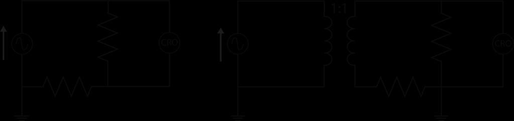
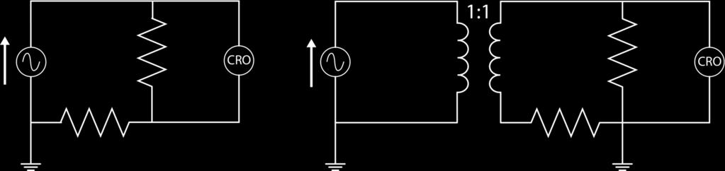
26 Insulation transformer - Measurement

27 Insulation transformer - Safety

28 Insulation transformer - 3 Damping
 ( V I I I V V A d Auto-transformer A A")
29 k N N N V V k N N N I I A A V I V I A ) ( ) ( V I I I V V A d Auto-transformer A A d
30 Rotating Electrical Machine Basically, it consists of: an electric circuit (inductor) originating the magnetic field; a magnetic circuit concentrating the field lines; an electric circuit (armature) experiencing electrodynamical force or electromotive force.
31 Ampère law i b
32 e Faraday law transformer effect b(t) e(t), i(t)
33 Faraday law (motional effect) b v e

34 Lorentz force b i F
35 stator inductor circuit air-gap rotor armature circuit
36 Magnetic field of a circular coil dl r db n B i B 0 i r n
37 B B j axis r axis B Rotating magnetic field (two-phase) I t r I n t r I B cos cos 0 0 t sen r I j n t sen r I n t r I B cos 0 0 0
38 j axis Rotating magnetic field (two-phase) II r axis B B B B B B 0I r I r 0 j t cos t j sent e

39 r axis B j axis 3 t j e r I B 3 0 Rotating magnetic field (three-phase): Ferraris field 0 cos n t r I B 0 3 cos n t r I B cos n t r I B
40 Three-phase asynchronous motor (induction motor) graphic symbol As a motor, it converts electric power into mechanical power
41 air gap shaft laminated stator and rotor ventilating fan three-phase inductor circuit
42 Wound rotor Squirrel-cage rotor W bar slip-ring commutator (single-phase) end ring
43 Induction motor: operating principle Inductor terminals are supplied by a three-phase symmetric voltage V A three-phase balanced current I is delivered to inductor windings. An induction field B rotating at speed N 0 = 0 f p - is originated (f current frequency, p number of poles, speed in rpm). In stator and rotor windings, subject to a sinusoidal magnetic flux F, electromotive forces E =. m f F and E =. m f F are induced, respectively. F max value of flux, E, rms value of electromotive force m, number of conductors in a winding
44 E three-phase balanced current I in the rotor windings Magnetic effect of I : a synchronous rotating field B (speed N 0 ) is originated, which tends to decrease the inductor rotating field B B depends on the applied voltage V and cannot vary voltage source V is forced to deliver an additional current I 3 to the inductor, such that rotating field B 3 due to I 3 compensates field B Mechanical effect of I : the axially-directed conductors placed in the radially-directed field B experience tangentially-directed forces F t The rotor experiences a torque C=RF t : if unconstrained, it rotates.
45 Having defined the slip factor s=(n 0 -N)/N 0 as the speed of the rotating field with respect to the rotor, the frequency of E and I is f =sf If the opposing torque is equal to zero then, the running torque C M =0 and f 0 I =0 E =0 f =0 s=0 N=N 0 the rotor is synchronous wrt the rotating field If the opposing torque is different from zero then, the running torque C M 0 and f 0 I 0 E 0 f 0 0<s< N<N 0 the rotor is asynchronous wrt the rotating field (the rotor follows the field)
46 Torque-speed curve Torque C is proportional to both flux F of the rotating field and real part of the armature current I cos f (active component): Current I and power factor cos f depend on emf E and armature circuit impedance: On the other hand, electromotive force E depends on both relative rotor speed N 0 -N and flux F It turns out to be: cos I k C F L s R Z resistive-inductive impedance R +jsl 0 ' F N N k E , V C N C C L N N R N R N N N k Z R Z E k C F F
47 Torque-speed curve C M self-starting C s = k F N 0 R /(R + L ) C Max torque C M = k F N 0 /(L ) when N = N 0 (-R /L ) C S operating point C R 0 N 0 N mechanical power P m = CN electric power P e = 3 VI cosf synchronous speed (rpm) 0f N 0 p
48 Speed control decreasing V decreasing f increasing R (wound rotor only) C C C N N N
49 Synchronous generator turbine alternator Three-phase output
50 Alternator structure Three-phase armature circuit DC inductor circuit (two-pole) In low-power alternators it can be replaced by a permanent magnet. As a generator, it converts mechanical power into electric power.
51 Alternator operating principle The inductor circuit is supplied by a DC current I E A magnetic flux F R sinusoidally distributed in the air-gap is originated A speed W is applied to the rotor shaft In the armature circuit a three-phase symmetric electromotive force E = kwf R at an angular frequency = Wp/ is induced If the armature circuit is on load, a three-phase (balanced) current I is delivered, so providing an active power P = 3EI cos f An equal amount of mechanical power must be supplied to the shaft Current I generates a synchronous rotating field (speed ), which originates a flux F S opposing flux F R In order to keep E constant, excitation current I E must be increased
52 electric frequency W p number of poles rotor speed I I Two-pole DC winding Four-pole DC winding
53 DC machine graphic symbol From electric to mechanical power: motor From mechanical to electric power: dynamo
54 air gap salient pole shaft laminated stator and rotor ventilating fan sliding brushes with commutator inductor armature
55 DC machine - Principle of operation I MOTOR Inductor circuit is supplied by DC voltage V E Current I E is originated Magnetic field B, and so flux F, take place Armature circuit is supplied by DC current I A Armature conductors, carrying axial current I A and placed in radial field B, are subject to tangential force F Main effect F C N P m = CN Secondary effect Due to the rotor motion, in the armature conductors an AC emf is induced, which is subsequently rectified by the multi-sector commutator. Therefore, a back emf E = knf appears at the commutator terminals. It turns out to be: E = V (V voltage across armature terminals) P e = EI A = CN = P m (power balance)
56 DC machine - Principle of operation II DYNAMO Inductor circuit is supplied by DC voltage V E Current I E is originated Magnetic field B, and so flux F, take place Rotor is given speed N, externally applied to the shaft In the armature conductors, an AC emf is induced At the commutator terminals a rectified emf E = knf is available Main effect If armature terminals are connected to a resistive load E I A P e = EI A Secondary effect Armature conductors, carrying axial current I A and placed in radial field B, are subject to tangential force F opposing the motion F C N P m = CN To maintain the motion, power P m must be supplied to the shaft (P m = P e ).
57 Multi-sector commutator: principle of operation A A a b b + b t t t B a a Each armature conductor is electrically connected to a sector. The polarity of each sector is reversed when crossing the A-B line joining the brushes (orthogonal to the pole axis). B with two conductors/sectors V AB t V AB The voltage V AB between brushes exhibits always the same polarity. with several conductors/sectors As a result, the original AC signal is mechanically transformed into a DC signal, and viceversa. t
58 I DC motor excitation schemes V E M Series excitation (motors for traction) When C res varies, both N and C vary in such a way that CN const (constant power motor) I E I A I E I A V E M V A V M Independent excitation Derived excitation When C res varies, excitation current I E varies N const (constant speed motor)
 k voltage constant Torque C k' FI A k' F V E R A k torque")
59 Equivalent circuit of the DC motor (with independent excitation) inductor circuit Excitation flux Induced emf (rectified) F F I E E knf armature circuit (R a resistance of armature conductor) k voltage constant Torque C k' FI A k' F V E R A k torque constant
 N 0 C S V k F k' F V R A C k 'F R")
60 Torque-speed curve (independent-excitation motor) self-starting F F(I E ) N 0 C S V k F k' F V R A C k 'F R A V knf CN
61 Speed control

62 AC to DC conversion - Ideal diode: current-voltage curve

63 AC to DC conversion - i R i i R Ri R Transformer + single phase rectifier

64 AC to DC conversion - 3 Single-phase rectifier (full-wave): principle of operation A rectified voltage v R is originated: non-zero average value


65 Wound synchronous motor Permanent magnet synchronous motor Magnets Excitation windings SPM Magnets IPM

66 Synchronous motor: torque-speed curve


67 Three-phase inverter Control system feedback Reference signal Rotor position sensor (Hall probe) Brushless DC motor: principle of operation

68 Stepping motor: principle of operation

69 Permanent-magnet stepping motor Variable-reluctance stepping motor
ROEVER COLLEGE OF ENGINEERING & TECHNOLOGY ELAMBALUR, PERAMBALUR DEPARTMENT OF ELECTRICAL AND ELECTRONICS ENGINEERING ELECTRICAL MACHINES I
 ROEVER COLLEGE OF ENGINEERING & TECHNOLOGY ELAMBALUR, PERAMBALUR-621220 DEPARTMENT OF ELECTRICAL AND ELECTRONICS ENGINEERING ELECTRICAL MACHINES I Unit I Introduction 1. What are the three basic types
Synchronous Machines
 Synchronous Machines Synchronous generators or alternators are used to convert mechanical power derived from steam, gas, or hydraulic-turbine to ac electric power Synchronous generators are the primary
Revision Guide for Chapter 15
 Revision Guide for Chapter 15 Contents tudent s Checklist Revision otes Transformer... 4 Electromagnetic induction... 4 Generator... 5 Electric motor... 6 Magnetic field... 8 Magnetic flux... 9 Force on
Synchronous Machines
 Synchronous Machines Synchronous Machines n 1 Φ f n 1 Φ f I f I f I f damper (run-up) winding Stator: similar to induction (asynchronous) machine ( 3 phase windings that forms a rotational circular magnetic
Revision Guide for Chapter 15
 Revision Guide for Chapter 15 Contents Revision Checklist Revision otes Transformer...4 Electromagnetic induction...4 Lenz's law...5 Generator...6 Electric motor...7 Magnetic field...9 Magnetic flux...
ECE 325 Electric Energy System Components 7- Synchronous Machines. Instructor: Kai Sun Fall 2015
 ECE 325 Electric Energy System Components 7- Synchronous Machines Instructor: Kai Sun Fall 2015 1 Content (Materials are from Chapters 16-17) Synchronous Generators Synchronous Motors 2 Synchronous Generators
UNIT I INTRODUCTION Part A- Two marks questions
 ROEVER COLLEGE OF ENGINEERING & TECHNOLOGY ELAMBALUR, PERAMBALUR-621220 DEPARTMENT OF ELECTRICAL AND ELECTRONICS ENGINEERING DESIGN OF ELECTRICAL MACHINES UNIT I INTRODUCTION 1. Define specific magnetic
NEPTUNE -code: KAUVG11ONC Prerequisites:... Knowledge description:
 Subject name: Electrical Machines Credits: 9 Requirement : Course director: Dr. Vajda István Position: Assessment and verification procedures: NEPTUNE -code: KAUVG11ONC Prerequisites:... Number of hours:
Chapter 15 Magnetic Circuits and Transformers
 Chapter 15 Magnetic Circuits and Transformers Chapter 15 Magnetic Circuits and Transformers 1. Understand magnetic fields and their interactio with moving charges. 2. Use the right-hand rule to determine
ELECTRICALMACHINES-I QUESTUION BANK
 ELECTRICALMACHINES-I QUESTUION BANK UNIT-I INTRODUCTION OF MAGNETIC MATERIAL PART A 1. What are the three basic rotating Electric machines? 2. Name the three materials used in machine manufacture. 3. What
Definition Application of electrical machines Electromagnetism: review Analogies between electric and magnetic circuits Faraday s Law Electromagnetic
 Definition Application of electrical machines Electromagnetism: review Analogies between electric and magnetic circuits Faraday s Law Electromagnetic Force Motor action Generator action Types and parts
3 d Calculate the product of the motor constant and the pole flux KΦ in this operating point. 2 e Calculate the torque.
 Exam Electrical Machines and Drives (ET4117) 11 November 011 from 14.00 to 17.00. This exam consists of 5 problems on 4 pages. Page 5 can be used to answer problem 4 question b. The number before a question
Module 3 Electrical Fundamentals
 3.1 Electron Theory Structure and distribution of electrical charges within: atoms, molecules, ions, compounds; Molecular structure of conductors, semiconductors and insulators. 3.2 Static Electricity
Review of Basic Electrical and Magnetic Circuit Concepts EE
 Review of Basic Electrical and Magnetic Circuit Concepts EE 442-642 Sinusoidal Linear Circuits: Instantaneous voltage, current and power, rms values Average (real) power, reactive power, apparent power,
EE 742 Chapter 3: Power System in the Steady State. Y. Baghzouz
 EE 742 Chapter 3: Power System in the Steady State Y. Baghzouz Transmission Line Model Distributed Parameter Model: Terminal Voltage/Current Relations: Characteristic impedance: Propagation constant: π
Prince Sattam bin Abdulaziz University College of Engineering. Electrical Engineering Department EE 3360 Electrical Machines (II)
") Chapter # 4 Three-Phase Induction Machines 1- Introduction (General Principles) Generally, conversion of electrical power into mechanical power takes place in the rotating part of an electric motor. In
Chapter # 4 Three-Phase Induction Machines 1- Introduction (General Principles) Generally, conversion of electrical power into mechanical power takes place in the rotating part of an electric motor. In
MODELING AND HIGH-PERFORMANCE CONTROL OF ELECTRIC MACHINES
 MODELING AND HIGH-PERFORMANCE CONTROL OF ELECTRIC MACHINES JOHN CHIASSON IEEE PRESS ü t SERIES ON POWER ENGINEERING IEEE Press Series on Power Engineering Mohamed E. El-Hawary, Series Editor The Institute
Electric Machines I Three Phase Induction Motor. Dr. Firas Obeidat
 Electric Machines I Three Phase Induction Motor Dr. Firas Obeidat 1 Table of contents 1 General Principles 2 Construction 3 Production of Rotating Field 4 Why Does the Rotor Rotate 5 The Slip and Rotor
Control of Wind Turbine Generators. James Cale Guest Lecturer EE 566, Fall Semester 2014 Colorado State University
 Control of Wind Turbine Generators James Cale Guest Lecturer EE 566, Fall Semester 2014 Colorado State University Review from Day 1 Review Last time, we started with basic concepts from physics such as
SECOND ENGINEER REG III/2 MARINE ELECTRO-TECHNOLOGY. 1. Understands the physical construction and characteristics of basic components.
 SECOND ENGINEER REG III/ MARINE ELECTRO-TECHNOLOGY LIST OF TOPICS A B C D Electric and Electronic Components Electric Circuit Principles Electromagnetism Electrical Machines The expected learning outcome
Chapter 1 Magnetic Circuits
 Principles of Electric Machines and Power Electronics Third Edition P. C. Sen Chapter 1 Magnetic Circuits Chapter 1: Main contents i-h relation, B-H relation Magnetic circuit and analysis Property of magnetic
Massachusetts Institute of Technology Department of Electrical Engineering and Computer Science Electric Machines
 Massachusetts Institute of Technology Department of Electrical Engineering and Computer Science 6.685 Electric Machines Problem Set 10 Issued November 11, 2013 Due November 20, 2013 Problem 1: Permanent
Introduction to Synchronous. Machines. Kevin Gaughan
 Introduction to Synchronous Machines Kevin Gaughan The Synchronous Machine An AC machine (generator or motor) with a stator winding (usually 3 phase) generating a rotating magnetic field and a rotor carrying
Basic Electrical Engineering SYLLABUS. Total No. of Lecture Hrs. : 50 Exam Marks : 80
 SYLLABUS Subject Code: /25 No. of Lecture Hrs./ Week : 04 IA Marks : 20 Exam Hours : 03 Total No. of Lecture Hrs. : 50 Exam Marks : 80 Course objectives: Impart a basic knowledge of electrical quantities
Chapter 5 Three phase induction machine (1) Shengnan Li
 Shengnan Li") Chapter 5 Three phase induction machine (1) Shengnan Li Main content Structure of three phase induction motor Operating principle of three phase induction motor Rotating magnetic field Graphical representation
Chapter 5 Three phase induction machine (1) Shengnan Li Main content Structure of three phase induction motor Operating principle of three phase induction motor Rotating magnetic field Graphical representation
Tutorial 1 (EMD) Rotary field winding
 Rotary field winding") Tutorial 1 (EMD) Rotary field winding The unchorded two-layer three-phase winding of a small synchronous fan drive for a computer has the following parameters: number of slots per pole and phase q = 1,
Tutorial 1 (EMD) Rotary field winding The unchorded two-layer three-phase winding of a small synchronous fan drive for a computer has the following parameters: number of slots per pole and phase q = 1,
Energy Converters. CAD and System Dynamics
 Institut für Elektrische Energiewandlung Energy Converters CAD and System Dynamics - Tutorials - Issue 2017/2018 M.Sc. Sascha Neusüs / M.Sc. Marcel Lehr Professor Dr.-Ing. habil. Dr. h.c. Andreas Binder
EN Power Electronics and Machines
 1/19 - Power Electronics and Machines Transformers Suryanarayana Doolla Department of Energy Science and Engineering Indian Institute of Technology, Bombay suryad@iitb.ac.in Lecture Organization - Modules
PESIT Bangalore South Campus Hosur road, 1km before Electronic City, Bengaluru -100 Department of Electronics & Communication Engineering
 QUESTION PAPER INTERNAL ASSESSMENT TEST 2 Date : /10/2016 Marks: 0 Subject & Code: BASIC ELECTRICAL ENGINEERING -15ELE15 Sec : F,G,H,I,J,K Name of faculty : Dhanashree Bhate, Hema B, Prashanth V Time :
ELECTRIC MACHINE TORQUE PRODUCTION 101
 ELECTRIC MACHINE TORQUE PRODUCTION 101 Best Electric Machine, 014 INTRODUCTION: The following discussion will show that the symmetrical (or true dual-ported) transformer electric machine as only provided
University of Jordan Faculty of Engineering & Technology Electric Power Engineering Department
 University of Jordan Faculty of Engineering & Technology Electric Power Engineering Department EE471: Electrical Machines-II Tutorial # 2: 3-ph Induction Motor/Generator Question #1 A 100 hp, 60-Hz, three-phase
EDEXCEL NATIONAL CERTIFICATE/DIPLOMA UNIT 5 - ELECTRICAL AND ELECTRONIC PRINCIPLES NQF LEVEL 3. OUTCOME 3 - MAGNETISM and INDUCTION
 EDEXCEL NATIONAL CERTIFICATE/DIPLOMA UNIT 5 - ELECTRICAL AND ELECTRONIC PRINCIPLES NQF LEVEL 3 OUTCOME 3 - MAGNETISM and INDUCTION 3 Understand the principles and properties of magnetism Magnetic field:
EC T32 - ELECTRICAL ENGINEERING
 EC T32 - ELECTRICAL ENGINEERING UNIT-I - TRANSFORMER 1. What is a transformer? 2. Briefly explain the principle of operation of transformers. 3. What are the parts of a transformer? 4. What are the types
Induction Motors. The single-phase induction motor is the most frequently used motor in the world
 Induction Motor The single-phase induction motor is the most frequently used motor in the world Most appliances, such as washing machines and refrigerators, use a single-phase induction machine Highly
Synchronous Machines
 Synchronous machine 1. Construction Generator Exciter View of a twopole round rotor generator and exciter. A Stator with laminated iron core C Slots with phase winding B A B Rotor with dc winding B N S
Module 3 : Sequence Components and Fault Analysis
 Module 3 : Sequence Components and Fault Analysis Lecture 12 : Sequence Modeling of Power Apparatus Objectives In this lecture we will discuss Per unit calculation and its advantages. Modeling aspects
The synchronous machine (detailed model)
") ELEC0029 - Electric Power System Analysis The synchronous machine (detailed model) Thierry Van Cutsem t.vancutsem@ulg.ac.be www.montefiore.ulg.ac.be/~vct February 2018 1 / 6 Objectives The synchronous
ELEC0029 - Electric Power System Analysis The synchronous machine (detailed model) Thierry Van Cutsem t.vancutsem@ulg.ac.be www.montefiore.ulg.ac.be/~vct February 2018 1 / 6 Objectives The synchronous
MAHARASHTRA STATE BOARD OF TECHNICAL EDUCATION
 Subject Code : 17331 (ETE) Model Answer Page No : 1 of 23 Important Instructions to examiners: 1) The answers should be examined by key words and not as word-to-word as given in the model answer scheme.
Lesson 17: Synchronous Machines
 Lesson 17: Synchronous Machines ET 332b Ac Motors, Generators and Power Systems Lesson 17_et332b.pptx 1 Learning Objectives After this presentation you will be able to: Explain how synchronous machines
Texas A & M University Department of Mechanical Engineering MEEN 364 Dynamic Systems and Controls Dr. Alexander G. Parlos
 Texas A & M University Department of Mechanical Engineering MEEN 364 Dynamic Systems and Controls Dr. Alexander G. Parlos Lecture 6: Modeling of Electromechanical Systems Principles of Motor Operation
Electromagnetics and Electric Machines Stefan Holst, CD-adapco
 Electromagnetics and Electric Machines Stefan Holst, CD-adapco Overview Electric machines intro Designing electric machines with SPEED Links to STAR-CCM+ for thermal modeling Electromagnetics in STAR-CCM+
Generators for wind power conversion
 Generators for wind power conversion B. G. Fernandes Department of Electrical Engineering Indian Institute of Technology, Bombay Email : bgf@ee.iitb.ac.in Outline of The Talk Introduction Constant speed
Chapter 4. Synchronous Generators. Basic Topology
 Basic Topology Chapter 4 ynchronous Generators In stator, a three-phase winding similar to the one described in chapter 4. ince the main voltage is induced in this winding, it is also called armature winding.
Introduction. Energy is needed in different forms: Light bulbs and heaters need electrical energy Fans and rolling miles need mechanical energy
 Introduction Energy is needed in different forms: Light bulbs and heaters need electrical energy Fans and rolling miles need mechanical energy What does AC and DC stand for? Electrical machines Motors
MAHARASHTRA STATE BOARD OF TECHNICAL EDUCATION
 Important Instructions to examiners: 1) The answers should be examined by key words and not as word-to-word as given in the model answer scheme. 2) The model answer and the answer written by candidate
ECEN 667 Power System Stability Lecture 18: Voltage Stability, Load Models
 ECEN 667 Power System Stability Lecture 18: Voltage Stability, Load Models Prof. Tom Overbye Dept. of Electrical and Computer Engineering Texas A&M University, overbye@tamu.edu 1 Announcements Read Chapter
SYLLABUS(EE-205-F) SECTION-B
 SECTION-B") SYLLABUS(EE-205-F) SECTION-A MAGNETIC CIRCUITS AND INDUCTION: Magnetic Circuits, Magnetic Materials and their properties, static and dynamic emfs and dforce on current carrying conductor, AC operation
SYLLABUS(EE-205-F) SECTION-A MAGNETIC CIRCUITS AND INDUCTION: Magnetic Circuits, Magnetic Materials and their properties, static and dynamic emfs and dforce on current carrying conductor, AC operation
Chapter 3 AUTOMATIC VOLTAGE CONTROL
 Chapter 3 AUTOMATIC VOLTAGE CONTROL . INTRODUCTION TO EXCITATION SYSTEM The basic function of an excitation system is to provide direct current to the field winding of the synchronous generator. The excitation
DESIGN OF ELECTRICAL APPARATUS SOLVED PROBLEMS
 DESIGN OF ELECTRICAL APPARATUS SOLVED PROBLEMS 1. A 350 KW, 500V, 450rpm, 6-pole, dc generator is built with an armature diameter of 0.87m and core length of 0.32m. The lap wound armature has 660 conductors.
Three Phase Circuits
 Amin Electronics and Electrical Communications Engineering Department (EECE) Cairo University elc.n102.eng@gmail.com http://scholar.cu.edu.eg/refky/ OUTLINE Previously on ELCN102 Three Phase Circuits Balanced
Equal Pitch and Unequal Pitch:
 Equal Pitch and Unequal Pitch: Equal-Pitch Multiple-Stack Stepper: For each rotor stack, there is a toothed stator segment around it, whose pitch angle is identical to that of the rotor (θs = θr). A stator
DIRECT-CURRENT MOTORS
 CHAPTER 4 DIRECT-CURRENT MOTORS Chapter Contributors Andrew E. Miller Earl F. Richards Alan W. Yeadon William H. Yeadon This chapter covers methods of calculating performance for direct-current (dc) mechanically
Electrical Machines and Energy Systems: Operating Principles (Part 1) SYED A Rizvi
 SYED A Rizvi") Electrical Machines and Energy Systems: Operating Principles (Part 1) SYED A Rizvi AC Machines Operating Principles: Rotating Magnetic Field The key to the functioning of AC machines is the rotating magnetic
Electrical Machines and Energy Systems: Operating Principles (Part 1) SYED A Rizvi AC Machines Operating Principles: Rotating Magnetic Field The key to the functioning of AC machines is the rotating magnetic
Generators. What its all about
 Generators What its all about How do we make a generator? Synchronous Operation Rotor Magnetic Field Stator Magnetic Field Forces and Magnetic Fields Force Between Fields Motoring Generators & motors are
Chapter 23 Magnetic Flux and Faraday s Law of Induction
 Chapter 23 Magnetic Flux and Faraday s Law of Induction 1 Overview of Chapter 23 Induced Electromotive Force Magnetic Flux Faraday s Law of Induction Lenz s Law Mechanical Work and Electrical Energy Generators
Ch. 23 Electromagnetic Induction, AC Circuits, And Electrical Technologies
 Ch. 23 Electromagnetic Induction, AC Circuits, And Electrical Technologies Induced emf - Faraday s Experiment When a magnet moves toward a loop of wire, the ammeter shows the presence of a current When
The initial magnetization curve shows the magnetic flux density that would result when an increasing magnetic field is applied to an initially
 MAGNETIC CIRCUITS The study of magnetic circuits is important in the study of energy systems since the operation of key components such as transformers and rotating machines (DC machines, induction machines,
EEE3405 ELECTRICAL ENGINEERING PRINCIPLES 2 - TEST
 ATTEMPT ALL QUESTIONS (EACH QUESTION 20 Marks, FULL MAKS = 60) Given v 1 = 100 sin(100πt+π/6) (i) Find the MS, period and the frequency of v 1 (ii) If v 2 =75sin(100πt-π/10) find V 1, V 2, 2V 1 -V 2 (phasor)
ECE 421/521 Electric Energy Systems Power Systems Analysis I 3 Generators, Transformers and the Per-Unit System. Instructor: Kai Sun Fall 2013
 ECE 41/51 Electric Energy Systems Power Systems Analysis I 3 Generators, Transformers and the Per-Unit System Instructor: Kai Sun Fall 013 1 Outline Synchronous Generators Power Transformers The Per-Unit
ENGG4420 LECTURE 7. CHAPTER 1 BY RADU MURESAN Page 1. September :29 PM
 CHAPTER 1 BY RADU MURESAN Page 1 ENGG4420 LECTURE 7 September 21 10 2:29 PM MODELS OF ELECTRIC CIRCUITS Electric circuits contain sources of electric voltage and current and other electronic elements such
Tutorial Sheet Fig. Q1
 Tutorial Sheet - 04 1. The magnetic circuit shown in Fig. Q1 has dimensions A c = A g = 9 cm 2, g = 0.050 cm, l c = 30 cm, and N = 500 turns. Assume the value of the relative permeability,µ r = 70,000
Mathematical Modeling and Dynamic Simulation of a Class of Drive Systems with Permanent Magnet Synchronous Motors
 Applied and Computational Mechanics 3 (2009) 331 338 Mathematical Modeling and Dynamic Simulation of a Class of Drive Systems with Permanent Magnet Synchronous Motors M. Mikhov a, a Faculty of Automatics,
Doubly salient reluctance machine or, as it is also called, switched reluctance machine. [Pyrhönen et al 2008]
![Doubly salient reluctance machine or, as it is also called, switched reluctance machine. [Pyrhönen et al 2008]](/thumbs/86/93665357.jpg "Doubly salient reluctance machine or, as it is also called, switched reluctance machine. [Pyrhönen et al 2008]") Doubly salient reluctance machine or, as it is also called, switched reluctance machine [Pyrhönen et al 2008] Pros and contras of a switched reluctance machine Advantages Simple robust rotor with a small
Doubly salient reluctance machine or, as it is also called, switched reluctance machine [Pyrhönen et al 2008] Pros and contras of a switched reluctance machine Advantages Simple robust rotor with a small
EE 212 PASSIVE AC CIRCUITS
 EE 212 PASSIVE AC CIRCUITS Condensed Text Prepared by: Rajesh Karki, Ph.D., P.Eng. Dept. of Electrical Engineering University of Saskatchewan About the EE 212 Condensed Text The major topics in the course
Dynamics of the synchronous machine
 ELEC0047 - Power system dynamics, control and stability Dynamics of the synchronous machine Thierry Van Cutsem t.vancutsem@ulg.ac.be www.montefiore.ulg.ac.be/~vct October 2018 1 / 38 Time constants and
Equivalent Circuits with Multiple Damper Windings (e.g. Round rotor Machines)
") Equivalent Circuits with Multiple Damper Windings (e.g. Round rotor Machines) d axis: L fd L F - M R fd F L 1d L D - M R 1d D R fd R F e fd e F R 1d R D Subscript Notations: ( ) fd ~ field winding quantities
Equivalent Circuits with Multiple Damper Windings (e.g. Round rotor Machines) d axis: L fd L F - M R fd F L 1d L D - M R 1d D R fd R F e fd e F R 1d R D Subscript Notations: ( ) fd ~ field winding quantities
Mathematical Modelling of Permanent Magnet Synchronous Motor with Rotor Frame of Reference
 Mathematical Modelling of Permanent Magnet Synchronous Motor with Rotor Frame of Reference Mukesh C Chauhan 1, Hitesh R Khunt 2 1 P.G Student (Electrical),2 Electrical Department, AITS, rajkot 1 mcchauhan1@aits.edu.in
STAR-CCM+ and SPEED for electric machine cooling analysis
 STAR-CCM+ and SPEED for electric machine cooling analysis Dr. Markus Anders, Dr. Stefan Holst, CD-adapco Abstract: This paper shows how two well established software programs can be used to determine the
MCE380: Measurements and Instrumentation Lab. Chapter 5: Electromechanical Transducers
 MCE380: Measurements and Instrumentation Lab Chapter 5: Electromechanical Transducers Part I Topics: Transducers and Impedance Magnetic Electromechanical Coupling Reference: Holman, CH 4. Cleveland State
CURRENT-CARRYING CONDUCTORS / MOVING CHARGES / CHARGED PARTICLES IN CIRCULAR ORBITS
 PHYSICS A2 UNIT 4 SECTION 4: MAGNETIC FIELDS CURRENT-CARRYING CONDUCTORS / MOVING CHARGES / CHARGED PARTICLES IN CIRCULAR ORBITS # Questions MAGNETIC FLUX DENSITY 1 What is a magnetic field? A region in
Lecture 7: Synchronous Motor Drives
 1 / 46 Lecture 7: Synchronous Motor Drives ELEC-E8402 Control of Electric Drives and Power Converters (5 ECTS) Marko Hinkkanen Spring 2017 2 / 46 Learning Outcomes After this lecture and exercises you
RLC Circuit (3) We can then write the differential equation for charge on the capacitor. The solution of this differential equation is
 We can then write the differential equation for charge on the capacitor. The solution of this differential equation is") RLC Circuit (3) We can then write the differential equation for charge on the capacitor The solution of this differential equation is (damped harmonic oscillation!), where 25 RLC Circuit (4) If we charge
RLC Circuit (3) We can then write the differential equation for charge on the capacitor The solution of this differential equation is (damped harmonic oscillation!), where 25 RLC Circuit (4) If we charge
Sliding Conducting Bar
 Motional emf, final For equilibrium, qe = qvb or E = vb A potential difference is maintained between the ends of the conductor as long as the conductor continues to move through the uniform magnetic field
Electromagnetic Induction and Faraday s Law
 Electromagnetic Induction and Faraday s Law Induced EMF Almost 200 years ago, Faraday looked for evidence that a magnetic field would induce an electric current with this apparatus: He found no evidence
Induction_P1. 1. [1 mark]
![Induction_P1. 1. [1 mark]](/thumbs/88/115570773.jpg "Induction_P1. 1. [1 mark]") Induction_P1 1. [1 mark] Two identical circular coils are placed one below the other so that their planes are both horizontal. The top coil is connected to a cell and a switch. The switch is closed and
Induction_P1 1. [1 mark] Two identical circular coils are placed one below the other so that their planes are both horizontal. The top coil is connected to a cell and a switch. The switch is closed and
Flux: Examples of Devices
 Flux: Examples of Devices xxx Philippe Wendling philippe.wendling@magsoft-flux.com Create, Design, Engineer! www.magsoft-flux.com www.cedrat.com Solenoid 2 1 The Domain Axisymmetry Open Boundary 3 Mesh
EE Branch GATE Paper 2010
 Q.1 Q.25 carry one mark each 1. The value of the quantity P, where, is equal to 0 1 e 1/e 2. Divergence of the three-dimensional radial vector field is 3 1/r 3. The period of the signal x(t) = 8 is 0.4
EE 410/510: Electromechanical Systems Chapter 4
 EE 410/510: Electromechanical Systems Chapter 4 Chapter 4. Direct Current Electric Machines and Motion Devices Permanent Magnet DC Electric Machines Radial Topology Simulation and Experimental Studies
Transformer. Transformer comprises two or more windings coupled by a common magnetic circuit (M.C.).
.") . Transformers Transformer Transformer comprises two or more windings coupled by a common magnetic circuit (M.C.). f the primary side is connected to an AC voltage source v (t), an AC flux (t) will be
. Transformers Transformer Transformer comprises two or more windings coupled by a common magnetic circuit (M.C.). f the primary side is connected to an AC voltage source v (t), an AC flux (t) will be
UJET VOL. 2, NO. 2, DEC Page 8
 UMUDIKE JOURNAL OF ENGINEERING AND TECHNOLOGY (UJET) VOL. 2, NO. 2, DEC 2016 PAGE 8-15 FINITE ELEMENT ANALYSIS OF A 7.5KW ASYNCHRONOUS MOTOR UNDER INTERMITTENT LOADING. Abunike, E. C. and Okoro, O. I.
Chapter # 1 Three-Phase Winding, EMF's and MMF's
 Chapter # 1 Three-Phase Winding, EMF's and MMF's 1. Introduction standard A.C. generators or alternators (as they are usually called) operate on the same fundamental principles of electromagnetic induction
Generalized Theory of Electrical Machines- A Review
 Generalized Theory of Electrical Machines- A Review Dr. Sandip Mehta Department of Electrical and Electronics Engineering, JIET Group of Institutions, Jodhpur Abstract:-This paper provides an overview
R. W. Erickson. Department of Electrical, Computer, and Energy Engineering University of Colorado, Boulder
 R. W. Erickson Department of Electrical, Computer, and Energy Engineering University of Colorado, Boulder Part III. Magnetics 13 Basic Magnetics Theory 14 Inductor Design 15 Transformer Design 1 Chapter
a. Type 0 system. b. Type I system. c. Type 2 system. d. Type 3 system.
 1-The steady-state error of a feedback control system with an acceleration input becomes finite in a a. Type 0 system. b. Type I system. c. Type 2 system. d. Type 3 system. 2-A good control system has
Eddy Current Heating in Large Salient Pole Generators
 Eddy Current Heating in Large Salient Pole Generators C.P.Riley and A.M. Michaelides Vector Fields Ltd., 24 Bankside, Kidlington, Oxford OX5 1JE, UK phone: (+44) 1865 370151, fax: (+44) 1865 370277 e-mail:
School of Mechanical Engineering Purdue University. ME375 ElectroMechanical - 1
 Electro-Mechanical Systems DC Motors Principles of Operation Modeling (Derivation of fg Governing Equations (EOM)) Block Diagram Representations Using Block Diagrams to Represent Equations in s - Domain
ELECTRICAL ENGINEERING
 ELECTRICAL ENGINEERING Subject Code: EE Course Structure Sections/Units Section A Unit 1 Unit 2 Unit 3 Unit 4 Unit 5 Unit 6 Unit 7 Section B Section C Section D Section E Section F Section G Section H
The synchronous machine (SM) in the power system (2) (Where does the electricity come from)?
 in the power system (2) (Where does the electricity come from)?") 1 The synchronous machine (SM) in the power system (2) (Where does the electricity come from)? 2 Lecture overview Synchronous machines with more than 2 magnetic poles The relation between the number of
1 The synchronous machine (SM) in the power system (2) (Where does the electricity come from)? 2 Lecture overview Synchronous machines with more than 2 magnetic poles The relation between the number of
Measurements of a 37 kw induction motor. Rated values Voltage 400 V Current 72 A Frequency 50 Hz Power 37 kw Connection Star
 Measurements of a 37 kw induction motor Rated values Voltage 4 V Current 72 A Frequency 5 Hz Power 37 kw Connection Star Losses of a loaded machine Voltage, current and power P = P -w T loss in Torque
CHAPTER 8 DC MACHINERY FUNDAMENTALS
 CHAPTER 8 DC MACHINERY FUNDAMENTALS Summary: 1. A Simple Rotating Loop between Curved Pole Faces - The Voltage Induced in a Rotating Loop - Getting DC voltage out of the Rotating Loop - The Induced Torque
Thermal Analysis & Design Improvement of an Internal Air-Cooled Electric Machine Dr. James R. Dorris Application Specialist, CD-adapco
 Thermal Analysis & Design Improvement of an Internal Air-Cooled Electric Machine Dr. James R. Dorris Application Specialist, CD-adapco Thermal Analysis of Electric Machines Motivation Thermal challenges
CHAPTER 3 INFLUENCE OF STATOR SLOT-SHAPE ON THE ENERGY CONSERVATION ASSOCIATED WITH THE SUBMERSIBLE INDUCTION MOTORS
 38 CHAPTER 3 INFLUENCE OF STATOR SLOT-SHAPE ON THE ENERGY CONSERVATION ASSOCIATED WITH THE SUBMERSIBLE INDUCTION MOTORS 3.1 INTRODUCTION The electric submersible-pump unit consists of a pump, powered by
Finite Element Analysis of Hybrid Excitation Axial Flux Machine for Electric Cars
 223 Finite Element Analysis of Hybrid Excitation Axial Flux Machine for Electric Cars Pelizari, A. ademir.pelizari@usp.br- University of Sao Paulo Chabu, I.E. ichabu@pea.usp.br - University of Sao Paulo
The simplest type of alternating current is one which varies with time simple harmonically. It is represented by
 ALTERNATING CURRENTS. Alternating Current and Alternating EMF An alternating current is one whose magnitude changes continuously with time between zero and a maximum value and whose direction reverses
LESSON 20 ALTERNATOR OPERATION OF SYNCHRONOUS MACHINES
 ET 332b Ac Motors, Generators and Power Systems LESSON 20 ALTERNATOR OPERATION OF SYNCHRONOUS MACHINES 1 LEARNING OBJECTIVES After this presentation you will be able to: Interpret alternator phasor diagrams
JRE SCHOOL OF Engineering
 JRE SCHOOL OF Engineering Class Test-1 Examinations September 2014 Subject Name Electromechanical Energy Conversion-II Subject Code EEE -501 Roll No. of Student Max Marks 30 Marks Max Duration 1 hour Date
ELECTROMAGNETIC INDUCTION
 ELECTROMAGNETIC INDUCTION 1. Magnetic Flux 2. Faraday s Experiments 3. Faraday s Laws of Electromagnetic Induction 4. Lenz s Law and Law of Conservation of Energy 5. Expression for Induced emf based on
Applied Electronics and Electrical Machines
 School of Electrical and Computer Engineering Applied Electronics and Electrical Machines (ELEC 365) Fall 2015 DC Machines 1 DC Machines Key educational goals: Develop the basic principle of operation
Electromagnetic Induction
 lectromagnetic Induction Induced MF We already know that moving charge (=current) causes magnetic field It also works the other way around: changing magnetic field (e.g. moving permanent magnet) causes
EE155/255 Green Electronics
 EE155/255 Green Electronics Electric Motors 10/16/17 Prof. William Dally Computer Systems Laboratory Stanford University Course Logistics Solar day is Monday 10/23 HW 3 is due today HW 4 out, due next