SHOTCRETE OR FRP JACKETING OF CONCRETE COLUMNS FOR SEISMIC RETROFITTING
|
|
|
- Ariel Fowler
- 5 years ago
- Views:
Transcription
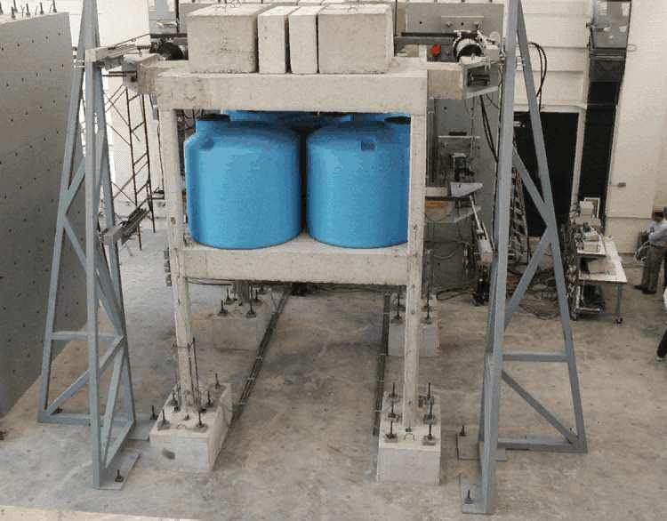
1 SfP PROJECT 9773: SEISMIC ASSESSMENT AND REHABILITATION OF EXISTING BUILDINGS INTERNATIONAL CLOSING WORKSHOP ISTANBUL, 3 MAY-JUNE, 5 SHOTCRETE OR FRP JACKETING OF CONCRETE COLUMNS FOR SEISMIC RETROFITTING S.N. BOUSIAS, M.N. FARDIS, A.-L. SPATHIS, D. BISKINIS Structures Laboratory, Department of Civil Engineering, University of Patras, Greece
2 RC Jacketing is widely used & cost-effective for RC buildings: familiar to engineers & construction industry; suitable for repair of damage; jacket can encapsulate members & joints providing structural continuity; multiple effects on stiffness, flexural/shear resistance, deformation capacity, anchorage & continuity of reinforcement. FRP wrapping of member ends is becoming the method of choice: very effective for confinement & shear strengthening; less disruption of building use by retrofitting.
3 Part I: Tests on individual columns w/ or w/o shotcrete or FRP jackets; Design expression or rules for: strength, stiffness & deformation capacity of columns w/ shotcrete or FRP jacket, including effect ect of lap splicing in original column.


4 EXPERIMENTAL CAMPAIGN ON RETROFITTING OF RC COLUMNS Total of 39 tests on RC columns, w/ ribbed (deformed) or smooth/hooked bars, w/ or w/o bar lap-splicing in the plastic hinge, cyclically tested to ultimate deformation under const. axial load: 9 unretrofitted controls; 5 columns retrofitted w/ or 4 layers of CFRP at different heights from base; 5 columns retrofitted w/ full-height concrete jacket,, including investigation of different connection at the interface of jacket & old column. Results supplemented w/ data from the literature (mainly on retrofitted columns w/o bar lap-splicing) to derive/calibrate expressions for: The flexural & shear force resistance of retrofitted columns, M y, V R ; The effective stiffness of retrofitted columns at incipient yielding, EI eff =M y L s /3 as determined from the yield moment M y and the chord rotation at yielding, The ultimate chord rotation of flexure-controlled retrofitted columns, as affected by any lap-splices of bars in original column. u y, y ;


5 Φ Φ Φ Φ Φ Φ 5 ~85 8/ ~ ~ / 8 CFRP Retrofitting 75 mm Shotcrete Retrofitting
6 E u,mσ E.75 u,m- E y E.75 um Check only if Near Collapse (NC) Limit State not checked, using NC criteria with V E from analysis σ u,mσ Example of possible use of results: RC member verifications in terms of chord rotation at yielding or ultimate EN Annex Limit State:Damage Limitation Significant Damage Member: ductile secondary brittle secondary E, V E y um : ductile primary brittle primary Near Collapse E um V E V Rd,EC, V E V Rd,EC8 /.5 V E V Rm,EC, V E V Rm,EC8 chord rotation & shear force demand from analysis (if linear, V E from capacity design); chord rotation at yielding; expected value of ultimate chord rotation; mean-minus-sigma ultimate chord rotation; V Rd, V Rm shear resistance, w/ or w/o material safety factors, respectively; V R,EC V R,EC8 shear resistance in monotonic loading; shear resistance in cyclic loading after flexural yielding.
7 EN998-3 Annex A: Chord-rotation at member yielding Ls + z h db f y Beams, rect. columns: y = φy φ y 3 + L + s fc L d s + z Ls b f y Walls: y = φy +. max[, ] +. 3φ y 3 8h fc φ y : yield curvature (via st principles, adapted to median M y ); L s = M/V: shear span at member end (~L/); z~.9d: tension shift (= if member not diagonally cracked by shear at flexural yielding: M y /L s ); h : section depth; f y, f c : MPa; d b : bar diameter; Last term: Due to bar slip from anchorage zone beyond member end (omitted if such slippage not possible)
8 α EN998-3 Annex A: Seismically-detailed members w/ rect. web Expected value of ultimate chord rotation (% drop in resistance) α st,pl :.45 for hot-rolled ductile steel or heat-treated (tempcore);.75 for brittle cold-worked steel; α wall : for shear walls; ω, ω': mechanical ratio of tension (including web) & compression steel; ν: N/bhf c (b: width of compression zone; N> for compression); L s /h : M/Vh: shear span ratio; s : confinement effectiveness factor : α = h s h ρ sx : A sh /b w s h : transverse steel ratio // direction (x) of loading; bc h ρ d : ratio of diagonal reinforcement. Non-seismically detailed members w/o lap splices - cyclic loading Plastic part, pl um = ( )( ν.4a. ) = + α 5 um y st, pl wall um - y max max (., ') (., ω ).3 f.35 yw αρ ω L sx. s f c f c 5, of ultimate chord rotation is multiplied by.85. h c ( ρ ).75 d b i 6bch c
9 ω α ρ ω α Test- um model comparison (# 4, median=., C.o.V=3.3%) Members w/ or w/o seismic detailing, w/ ribbed bars lap-spliced over l o in plastic hinge region Compression reinforcement counts as double. For yield properties M y, φ y, y : f y of tension steel multiplied x l o /l oy,min if l o <l oy,min =(.3f y / For ultimate chord rotation um = y +pl um : pl um x l o /l ou,min if l o <l ou,min =d b f y /[( rs f y, f c in MPa, sx = sx f yw /f c : mech. transverse steel ratio // loading, rs =(-s h /b o )(-s h /b o )n restr /n tot (n restr /n tot restrained-to-total lap-spliced bars). f c )d b sx ) f c ], Test-M y model comparison (# 8, median=.5, C.o.V=.9%) 4 Test- y model comparison (# 6, median=.5, C.o.V=8.9%) M y 9 8 y 9 8 u 7 7 M y,exp (knm) 8 6 u,exp(%) u,exp(%) UoP test b&c other sources walls M y,pred (knm) UoP test b&c other sources walls u,pred (%) Test-EI eff model comparison (# 6, median=.975, C.o.V=3.3%) UoP test b&c other sources walls u,pred (%)


10 Concrete Jackets
11 Concrete Jackets (continued/anchored in joint; w/ or w/o lap splices in old member) Calculation assumptions: Full composite action of jacket & old concrete assumed (jacketed member: monolithic ), even for minimal shear connection at interface (roughened interface, steel dowels epoxied into old concrete: useful but not essential); f c of monolithic member = that of the jacket (avoid large differences in old & new f c ) Axial load considered to act on full, composite section; Longitudinal reinforcement of jacketed column: mainly that of the jacket. Vertical bars of old column considered at actual location between tension & compression bars of composite member (~ web longitudinal reinforcement), with its own f y ; Only the transverse reinforcement of the jacket considered for confinement; For shear resistance, the old transverse reinforcement taken into account only in walls, if anchored in the (new) boundary elements. Then: M R & M y of jacketed member: ~% of y of jacketed member for pre-yield (elastic) stiffness: if roughening of interface ~5%, if no roughening ~% of Shear resistance of jacketed member: Flexure-controlled ultimate deformation u : ~9% of ~% of those of monolithic member calculated w/ assumptions above. Concrete Jackets w/ bars not continued/anchored in joint: Jacket considered only to confine the full old section.
12 # 54 members w/ or w/o lap splices: test-to-calculation after RC-jacketing M y,exp/ M y,th M. y. a Present tests: Other tests: ± stand. deviation bounds, pure scatter ± stand. deviation bounds, monolithic members no laps 5db plain 3db plain continuous jacket bars group average 5db deformed 5db plain 45db deformed discontinuous jacket bars standard deviation of group mean y,th y,exp/ y EI exp / EI th *y) u pl + u,exp / ( EI eff. a b c d e f g h i j k a b c d e f g h i j k a: no treatment, b: no treatment, predamaged, c: welded U-bars, d: dowels, e: roughened, f: roughened, predamaged, g: U-bars & roughened, h: U-bars & roughened, predamaged, i: roughened & dowels, j: roughened & dowels, predamaged, k: monolithic.4. u


13 FRP Jackets
; Flexure-controlled ultimate deformation, u : confinement factor due to stirrups enhanced due to FRP confinement by")
14 ρ ε ε ε ε FRP Jackets (not continued/anchored in joint; w/o lap splices in old member Rectangular X-section w/ continuous longitudinal bars (no lap splices): M R & M y, pre-yield (elastic) stiffness EI eff of RC member: not significantly enhanced by FRP jacket (increase neglected); Flexure-controlled ultimate deformation, u : confinement factor due to stirrups enhanced due to FRP confinement by f f f,e/f c f =t f /b w : FRP ratio; f f,e : FRP effective strength: f f,e min fu,f, ε u,f E f.7 min fu,f, εu,f E where: f u,f, E f : FRP tensile strength & Modulus; u,f: FRP limit strain; CFRP, AFRP: u,f=.5; GFRP: u,f=.; polyacetal FRP: ( h R) + ( b R) α = 3bh ρ α ρ f ( ) ( ) f f = c u,f=.3; confinement effectiveness: b, h: sides of X-section; R: radius at corner
15 u,exp(%) _ # FRP-wrapped members w/o lap splices: test-to-calculated ratio 5 3 M y.5 y # median=.4 C.o.V=8.8% M y,exp (knm) 5 # 5 median=. C.o.V=35.8% y,exp(%) _ M y,pred (knm) y,pred (%) 3 EI eff u # 5 median=. C.o.V=9% EI exp 5 5 # 9 median=. C.o.V=3.% EI pred upl + y (%)
16 ρ α ρ α f c in MPa, f=t f /b w : FRP ratio, f f,e : effective FRP strength in MPa, rs=4/n tot (n tot : total lap-spliced bars, only the 4 corner ones restrained). Test-M y model comparison Test- y model comparison Test- um model comparison (#, median=.65, C.o.V=9.%) (#, median=.85, C.o.V=8.9%) (# 6, median=., C.o.V=.7%) FRP Jackets (not continued/anchored in joint; w/ lap splices in old member) Rectangular X-section w/ longit. bars lap-spliced over l o in plastic hinge: Compression reinforcement counts as double. For yield properties M y, φ y, y : f y of tension steel multiplied x l o /l oy,min if l o <l oy,min =(.f y / f c )d b For ultimate chord rotation um = y +pl um : pl um calculated on the basis of confinement by te stirrups alone, multiplied x l o /l ou,min if l o <l ou,min =d b f y /[( rs f f f,e /f c ) f c ], M y.4. y 5 u 4 M y,exp (knm) 8 6 y,exp (%)..8.6 u,exp(%) UoP test other sources. UoP test other sources UoP test other sources M y,pred (knm) y,pred (%) u,pred (%) Test-EI eff model comparison (#, median=., C.o.V=%)
17 ρ ε ρ ρ FRP Jackets Shear resistance in cyclic loading past flexural yielding Shear resistance of FRP-jacketed member: h x V R = min µ + Ls h pl Ls ( N,.55Ac fc ) + (.5 min( 5, ).6 max(.5, ρtot ).6 min 5, fc Ac + Vw V f V f = min( u,f E u,f, f u,f ) f b w z/ contributes to member shear resistance as controlled by diagonal tension f :FRP ratio, f = t f /b w ; f u,f :FRP tensile strength; z : internal lever arm. Test-to-prediction ratio vs. #, median=.4, C.o.V=.9%: Total shear resistance of retrofitted member as controlled by diagonal tension, should not exceed shear resistance of old RC member as controlled by web crushing. Vu,exp / V u,pred ductility
18 Part II: Pseudodynamic test of.7: scale -story unsymmetric structure,, w/ or w/o FRP-retrofitting


19 ŷ d y r x CoG d xˆ R y r r y d x REFERENCE FRAME x ACTUATOR
20 Pseudodynamic tests of structure: Unretrofitted After repair of damage & FRP-wraps at all column ends (top & bottom, both stories). With nd story infilled & FRP-wraps at all column ends. 5sec Herceg-Novi (Montenegro 979) record, modified to fit EC8 spectrum on firm soil w/ PGA:.3g S a (m / s ) EC8 Record Period (s)
21
22 Story drifts - Unretrofitted structure at.3g Drift Displacement (m) Drift Displacement (rad) p8x (E->W)-Level - p8x (E->W)-Level Time (sec) Test was stopped before end of record, due to heavy damage at base of ground-story soft-side columns (lap splices): Peak drifts of soft-side columns: p8theta-level Ground story:.9% and.5% in orthogonal direction (simultaneous); nd story:.6% and.% in orthogonal direction (simultaneous). -.5 p8theta-level - Time (sec)
23 Column drifts - Unretrofitted structure at.3g 4 3 p8 Soft column - Lev. Stiff column - Lev..5 Col., Lev. Drift ratio (%) - - i-s Drift Ratio Y (%) Time p8 (sec) 4 Soft column - Lev. 3 Stiff column - Lev i-s Drift Ratio X (%).5 Col., Lev. Drift ratio (%) - - i-s Drift Ratio Y (%) Time (sec) i-s Drift Ratio X (%)
")
24 FRP-wraps at all column ends (top & bottom, both stories)
25 Story drifts and story force-displacement loops - FRP-wraps.3g.4.3 p px (E->W)-Level - px (E->W)-Level -..5 p ptheta-level - ptheta-level - Drift Displacement (m) Drift Displacement (rad) Time (sec) Time (sec) 6 px (E->W)-Level - 6 px (E->W)-Level Force (kn) - Force (kn) Displacement (m) Displacement (m)
26 Interstory drifts - FRP-wraps.3g (top & bottom, both stories) 4 p 4 p 3 3 Drift ratio (%) - Drift ratio (%) Soft column - Lev. Stiff column - Lev Time (sec) -3 Soft column - Lev. Stiff column - Lev Time (sec)

27 nd story infilled; FRPwraps at all column ends
-Level - px (E->W)-Level - Drift Displacement (m). -. -.4 -.6 4 6 8 4 6 Time (sec) p.")
28 Story drifts - nd story infilled; FRP-wraps at all column ends.6.4 p px (E->W)-Level - px (E->W)-Level - Drift Displacement (m) Time (sec) p.3 ptheta-level - ptheta-level -. Drift Displacement (rad) Time (sec)
29 nd story infilled; FRP-wraps at all column ends 8 6 px (E->W)-Level p Soft column - Lev. Stiff column - Lev. 4 4 Force (kn) - -4 Drift ratio (%) Displacement (m) Time (sec)
30 THANK YOU!
DEFORMATION CAPACITY OF OLDER RC SHEAR WALLS: EXPERIMENTAL ASSESSMENT AND COMPARISON WITH EUROCODE 8 - PART 3 PROVISIONS
 DEFORMATION CAPACITY OF OLDER RC SHEAR WALLS: EXPERIMENTAL ASSESSMENT AND COMPARISON WITH EUROCODE 8 - PART 3 PROVISIONS Konstantinos CHRISTIDIS 1, Emmanouil VOUGIOUKAS 2 and Konstantinos TREZOS 3 ABSTRACT
Eurocode 8 Part 3: Assessment and retrofitting of buildings
 in the Euro-Mediterranean Area Eurocode 8 Part 3: Assessment and retrofitting of buildings Paolo Emilio Pinto Università di Roma La Sapienza Urgency of guidance documents for assessment and retrofit in
SeismoBuild Verification Report (KANEPE) For version 2018
 For version 2018") SeismoBuild Verification Report (KANEPE) For version 2018 Copyright Copyright 2002-2018 Seismosoft Ltd. All rights reserved. SeismoBuild is a registered trademark of Seismosoft Ltd. Copyright law protects
SeismoBuild Verification Report (KANEPE) For version 2018 Copyright Copyright 2002-2018 Seismosoft Ltd. All rights reserved. SeismoBuild is a registered trademark of Seismosoft Ltd. Copyright law protects
Seismic Assessment of a RC Building according to FEMA 356 and Eurocode 8
 1 Seismic Assessment of a RC Building according to FEMA 356 and Eurocode 8 Ioannis P. GIANNOPOULOS 1 Key words: Pushover analysis, FEMA 356, Eurocode 8, seismic assessment, plastic rotation, limit states
Seismic performance evaluation of existing RC buildings designed as per past codes of practice
 Sādhanā Vol. 37, Part 2, April 2012, pp. 281 297. c Indian Academy of Sciences Seismic performance evaluation of existing RC buildings designed as per past codes of practice 1. Introduction K RAMA RAJU,
Design of a Multi-Storied RC Building
 Design of a Multi-Storied RC Building 16 14 14 3 C 1 B 1 C 2 B 2 C 3 B 3 C 4 13 B 15 (S 1 ) B 16 (S 2 ) B 17 (S 3 ) B 18 7 B 4 B 5 B 6 B 7 C 5 C 6 C 7 C 8 C 9 7 B 20 B 22 14 B 19 (S 4 ) C 10 C 11 B 23
Seismic Design of New R.C. Structures
 Seismic Design Philosophy Main Concepts Seismic Design of New R.C. Structures Prof. Stephanos E. Dritsos University of Patras, Greece. Energy dissipation Ductility Capacity design Learning from Earthquakes
Behavior and Modeling of Existing Reinforced Concrete Columns
 Behavior and Modeling of Existing Reinforced Concrete Columns Kenneth J. Elwood University of British Columbia with contributions from Jose Pincheira, Univ of Wisconsin John Wallace, UCLA Questions? What
OS MODELER - EXAMPLES OF APPLICATION Version 1.0. (Draft)
") OS MODELER - EXAMPLES OF APPLICATION Version 1.0 (Draft) Matjaž Dolšek February 2008 Content 1. Introduction... 1 2. Four-storey reinforced concrete frame designed according to EC8... 2 2.1. Description
OS MODELER - EXAMPLES OF APPLICATION Version 1.0 (Draft) Matjaž Dolšek February 2008 Content 1. Introduction... 1 2. Four-storey reinforced concrete frame designed according to EC8... 2 2.1. Description
Seismic Pushover Analysis Using AASHTO Guide Specifications for LRFD Seismic Bridge Design
 Seismic Pushover Analysis Using AASHTO Guide Specifications for LRFD Seismic Bridge Design Elmer E. Marx, Alaska Department of Transportation and Public Facilities Michael Keever, California Department
POST-PEAK BEHAVIOR OF FRP-JACKETED REINFORCED CONCRETE COLUMNS
 POST-PEAK BEHAVIOR OF FRP-JACKETED REINFORCED CONCRETE COLUMNS - Technical Paper - Tidarut JIRAWATTANASOMKUL *1, Dawei ZHANG *2 and Tamon UEDA *3 ABSTRACT The objective of this study is to propose a new
FRP Seismic Strengthening of Columns in Frames
 FRP Seismic Strengthening of Columns in Frames Dr Mihaela-Anca Ciupala (EU Marie Curie Research Fellow) Dr Kypros Pilakoutas (Reader) Professor Nicolae Taranu Centre for Cement and Concrete Department
CE5510 Advanced Structural Concrete Design - Design & Detailing of Openings in RC Flexural Members-
 CE5510 Advanced Structural Concrete Design - Design & Detailing Openings in RC Flexural Members- Assoc Pr Tan Kiang Hwee Department Civil Engineering National In this lecture DEPARTMENT OF CIVIL ENGINEERING
D : SOLID MECHANICS. Q. 1 Q. 9 carry one mark each. Q.1 Find the force (in kn) in the member BH of the truss shown.
 in the member BH of the truss shown.") D : SOLID MECHANICS Q. 1 Q. 9 carry one mark each. Q.1 Find the force (in kn) in the member BH of the truss shown. Q.2 Consider the forces of magnitude F acting on the sides of the regular hexagon having
D : SOLID MECHANICS Q. 1 Q. 9 carry one mark each. Q.1 Find the force (in kn) in the member BH of the truss shown. Q.2 Consider the forces of magnitude F acting on the sides of the regular hexagon having
Lap splice length and details of column longitudinal reinforcement at plastic hinge region
 Lap length and details of column longitudinal reinforcement at plastic hinge region Hong-Gun Park 1) and Chul-Goo Kim 2) 1), 2 Department of Architecture and Architectural Engineering, Seoul National University,
PEER/SSC Tall Building Design. Case study #2
 PEER/SSC Tall Building Design Case study #2 Typical Plan View at Ground Floor and Below Typical Plan View at 2 nd Floor and Above Code Design Code Design Shear Wall properties Shear wall thickness and
EUROCODE EN SEISMIC DESIGN OF BRIDGES
 Brussels, 18-20 February 2008 Dissemination of information workshop 1 EUROCODE EN1998-2 SEISMIC DESIGN OF BRIDGES Basil Kolias Basic Requirements Brussels, 18-20 February 2008 Dissemination of information
Consequently, retrofit of many poor existing structures is a very important issue. for Turkey!
 Turkey Placed on one of the most active tectonic plates in the world ~96% of the country is under the threat of earthquakes ~98% of the population are live with that risk. Istanbul 1 st degree of earthquake
Earthquake-resistant design of indeterminate reinforced-concrete slender column elements
 Engineering Structures 29 (2007) 163 175 www.elsevier.com/locate/engstruct Earthquake-resistant design of indeterminate reinforced-concrete slender column elements Gerasimos M. Kotsovos a, Christos Zeris
Chapter 4. Test results and discussion. 4.1 Introduction to Experimental Results
 Chapter 4 Test results and discussion This chapter presents a discussion of the results obtained from eighteen beam specimens tested at the Structural Technology Laboratory of the Technical University
Influence of column web stiffening on the seismic behaviour of beam-tocolumn
 Influence of column web stiffening on the seismic behaviour of beam-tocolumn joints A.L. Ciutina & D. Dubina The Politehnica University of Timisoara, Romania ABSTRACT: The present paper summarises the
SHEAR CAPACITY OF REINFORCED CONCRETE COLUMNS RETROFITTED WITH VERY FLEXIBLE FIBER REINFORCED POLYMER WITH VERY LOW YOUNG S MODULUS
 SHEAR CAPACITY OF REINFORCED CONCRETE COLUMNS RETROFITTED WITH VERY FLEXILE FIER REINFORCED POLYMER WITH VERY LOW YOUNG S MODULUS Hu Shaoqing Supervisor: Susumu KONO ** MEE8165 ASTRACT FRP with low Young
Finite Element Modelling with Plastic Hinges
 01/02/2016 Marco Donà Finite Element Modelling with Plastic Hinges 1 Plastic hinge approach A plastic hinge represents a concentrated post-yield behaviour in one or more degrees of freedom. Hinges only
Sabah Shawkat Cabinet of Structural Engineering Walls carrying vertical loads should be designed as columns. Basically walls are designed in
 Sabah Shawkat Cabinet of Structural Engineering 17 3.6 Shear walls Walls carrying vertical loads should be designed as columns. Basically walls are designed in the same manner as columns, but there are
Flexural Behavior of Brittle RC Members Rehabilitated with Concrete Jacketing
 Flexural Behavior of Brittle RC Members Rehabilitated with Concrete Jacketing G. E. Thermou, Ph.D. 1 ; S. J. Pantazopoulou, M.ASCE 2 ; and A. S. Elnashai, F.ASCE 3 Abstract: The composite flexural action
A PROPOSAL OF DESIGN PROCEDURE FOR FLEXURAL STRENGTHENING RC BEAMS WITH FRP SHEET
 N. Kishi, E-89, 1/8 A PROPOSAL OF DESIGN PROCEDURE FOR FLEXURAL STRENGTHENING RC BEAMS WITH FRP SHEET Yusuke Kurihashi Norimitsu Kishi Hiroshi Mikami Sumiyuki Sawada Civil Engrg. Research Muroran Inst.
Lecture-04 Design of RC Members for Shear and Torsion
 Lecture-04 Design of RC Members for Shear and Torsion By: Prof. Dr. Qaisar Ali Civil Engineering Department UET Peshawar drqaisarali@uetpeshawar.edu.pk www.drqaisarali.com 1 Topics Addressed Design of
Design of Reinforced Concrete Beam for Shear
 Lecture 06 Design of Reinforced Concrete Beam for Shear By: Prof Dr. Qaisar Ali Civil Engineering Department UET Peshawar drqaisarali@uetpeshawar.edu.pk 1 Topics Addressed Shear Stresses in Rectangular
Seismic Design, Assessment & Retrofitting of Concrete Buildings. fctm. h w, 24d bw, 175mm 8d bl, 4. w 4 (4) 2 cl
 2 cl") Seismic Design, Assessment & Retroitting o Concrete Buildings Table 5.1: EC8 rules or detailing and dimensioning o primary beams (secondary beams: as in DCL) DC H DCM DCL critical region length 1.5h w
Seismic Design, Assessment & Retroitting o Concrete Buildings Table 5.1: EC8 rules or detailing and dimensioning o primary beams (secondary beams: as in DCL) DC H DCM DCL critical region length 1.5h w
Flexure: Behavior and Nominal Strength of Beam Sections
 4 5000 4000 (increased d ) (increased f (increased A s or f y ) c or b) Flexure: Behavior and Nominal Strength of Beam Sections Moment (kip-in.) 3000 2000 1000 0 0 (basic) (A s 0.5A s ) 0.0005 0.001 0.0015
Coupling Beams of Shear Walls
 Coupling Beams of Shear Walls Modelling Procedure for the Seismic Analysis of RC Structures João Miguel Damião Bezelga (1) July 215 (1) Instituto Superior Técnico Universidade de Lisboa, Av. Rovisco Pais,
Displacement-based methods EDCE: Civil and Environmental Engineering CIVIL Advanced Earthquake Engineering
 Displacement-based methods EDCE: Civil and Environmental Engineering CIVIL 706 - Advanced Earthquake Engineering EDCE-EPFL-ENAC-SGC 2016-1- Content! Link to force-based methods! Assumptions! Reinforced
SHEAR DESIGN EQUATIONS FOR FRP RC BEAMS
 SHEAR DESIGN EQUATIONS FOR FRP RC BEAMS Dr. Maurizio Guadagnini Dr. Kypros Pilakoutas Professor Peter Waldron Centre for Dept. of Civil and Structural Engineering The University of Sheffield, UK Outline
CONSULTING Engineering Calculation Sheet. Job Title Member Design - Reinforced Concrete Column BS8110
 E N G I N E E R S Consulting Engineers jxxx 1 Job Title Member Design - Reinforced Concrete Column Effects From Structural Analysis Axial force, N (tension-ve and comp +ve) (ensure >= 0) 8000kN OK Major
Design of Reinforced Concrete Structures (II)
") Design of Reinforced Concrete Structures (II) Discussion Eng. Mohammed R. Kuheil Review The thickness of one-way ribbed slabs After finding the value of total load (Dead and live loads), the elements are
Design of Reinforced Concrete Structures (II) Discussion Eng. Mohammed R. Kuheil Review The thickness of one-way ribbed slabs After finding the value of total load (Dead and live loads), the elements are
ε t increases from the compressioncontrolled Figure 9.15: Adjusted interaction diagram
 CHAPTER NINE COLUMNS 4 b. The modified axial strength in compression is reduced to account for accidental eccentricity. The magnitude of axial force evaluated in step (a) is multiplied by 0.80 in case
CHAPTER 5. T a = 0.03 (180) 0.75 = 1.47 sec 5.12 Steel moment frame. h n = = 260 ft. T a = (260) 0.80 = 2.39 sec. Question No.
 0.75 = 1.47 sec 5.12 Steel moment frame. h n = = 260 ft. T a = (260) 0.80 = 2.39 sec. Question No.") CHAPTER 5 Question Brief Explanation No. 5.1 From Fig. IBC 1613.5(3) and (4) enlarged region 1 (ASCE 7 Fig. -3 and -4) S S = 1.5g, and S 1 = 0.6g. The g term is already factored in the equations, thus
CHAPTER 5 Question Brief Explanation No. 5.1 From Fig. IBC 1613.5(3) and (4) enlarged region 1 (ASCE 7 Fig. -3 and -4) S S = 1.5g, and S 1 = 0.6g. The g term is already factored in the equations, thus
EFFECT OF SHEAR REINFORCEMENT ON FAILURE MODE OF RC BRIDGE PIERS SUBJECTED TO STRONG EARTHQUAKE MOTIONS
 EFFECT OF SHEAR REINFORCEMENT ON FAILURE MODE OF RC BRIDGE PIERS SUBJECTED TO STRONG EARTHQUAKE MOTIONS Atsuhiko MACHIDA And Khairy H ABDELKAREEM SUMMARY Nonlinear D FEM was utilized to carry out inelastic
Strengthening of columns with FRP
 with FRP Professor Dr. Björn Täljsten Luleå University of Technology Sto Scandinavia AB 9/12/2013 Agenda Case study Restrained transverse expansion (confinement) Circular and rectangular cross sections
ULTIMATE SHEAR OF BEAMS STRENGTHENED WITH CFRP SHEETS
 ULTIMATE SHEAR OF BEAMS STRENGTHENED WITH CFRP SHEETS U. Ianniruberto and M. Imbimbo Department of Civil Engineering, University of Rome Tor Vergata Via di Tor Vergata 0, 0033, Rome, Italy SUMMARY: The
Chapter 8. Shear and Diagonal Tension
 Chapter 8. and Diagonal Tension 8.1. READING ASSIGNMENT Text Chapter 4; Sections 4.1-4.5 Code Chapter 11; Sections 11.1.1, 11.3, 11.5.1, 11.5.3, 11.5.4, 11.5.5.1, and 11.5.6 8.2. INTRODUCTION OF SHEAR
Design of AAC wall panel according to EN 12602
 Design of wall panel according to EN 160 Example 3: Wall panel with wind load 1.1 Issue Design of a wall panel at an industrial building Materials with a compressive strength 3,5, density class 500, welded
Parametric analysis and torsion design charts for axially restrained RC beams
 Structural Engineering and Mechanics, Vol. 55, No. 1 (2015) 1-27 DOI: http://dx.doi.org/10.12989/sem.2015.55.1.001 1 Parametric analysis and torsion design charts for axially restrained RC beams Luís F.A.
Design of Reinforced Concrete Beam for Shear
 Lecture 06 Design of Reinforced Concrete Beam for Shear By: Civil Engineering Department UET Peshawar drqaisarali@uetpeshawar.edu.pk Topics Addressed Shear Stresses in Rectangular Beams Diagonal Tension
Performance Modeling Strategies for Modern Reinforced Concrete Bridge Columns
 Performance Modeling Strategies for Modern Reinforced Concrete Bridge Columns Michael P. Berry Marc O. Eberhard University of Washington Project funded by the Pacific Earthquake Engineering Research Center
Annex - R C Design Formulae and Data
 The design formulae and data provided in this Annex are for education, training and assessment purposes only. They are based on the Hong Kong Code of Practice for Structural Use of Concrete 2013 (HKCP-2013).
Seismic design of bridges
 NATIONAL TECHNICAL UNIVERSITY OF ATHENS LABORATORY FOR EARTHQUAKE ENGINEERING Seismic design of bridges Lecture 3 Ioannis N. Psycharis Capacity design Purpose To design structures of ductile behaviour
Structural Steelwork Eurocodes Development of A Trans-national Approach
 Structural Steelwork Eurocodes Development of A Trans-national Approach Course: Eurocode Module 7 : Worked Examples Lecture 0 : Simple braced frame Contents: 1. Simple Braced Frame 1.1 Characteristic Loads
Seismic Performance of High-rise RC Wall-type Buildings in Korea
 Seismic Performance of High-rise RC Wall-type Buildings in Korea December 2 th, 24 Han Seon Lee Professor, Korea University, Seoul, Korea Structural Concrete Engineering Lab. Ratio of Apartments / Total
Nonlinear static analysis PUSHOVER
 Nonlinear static analysis PUSHOVER Adrian DOGARIU European Erasmus Mundus Master Course Sustainable Constructions under Natural Hazards and Catastrophic Events 520121-1-2011-1-CZ-ERA MUNDUS-EMMC Structural
CHAPTER 4. ANALYSIS AND DESIGN OF COLUMNS
 4.1. INTRODUCTION CHAPTER 4. ANALYSIS AND DESIGN OF COLUMNS A column is a vertical structural member transmitting axial compression loads with or without moments. The cross sectional dimensions of a column
CHAPTER 6: ULTIMATE LIMIT STATE
 CHAPTER 6: ULTIMATE LIMIT STATE 6.1 GENERAL It shall be in accordance with JSCE Standard Specification (Design), 6.1. The collapse mechanism in statically indeterminate structures shall not be considered.
Design of reinforced concrete sections according to EN and EN
 Design of reinforced concrete sections according to EN 1992-1-1 and EN 1992-2 Validation Examples Brno, 21.10.2010 IDEA RS s.r.o. South Moravian Innovation Centre, U Vodarny 2a, 616 00 BRNO tel.: +420-511
twenty one concrete construction: shear & deflection ARCHITECTURAL STRUCTURES: FORM, BEHAVIOR, AND DESIGN DR. ANNE NICHOLS SUMMER 2014 lecture
 ARCHITECTURAL STRUCTURES: FORM, BEHAVIOR, AND DESIGN DR. ANNE NICHOLS SUMMER 2014 lecture twenty one concrete construction: Copyright Kirk Martini shear & deflection Concrete Shear 1 Shear in Concrete
International Journal of Scientific & Engineering Research Volume 9, Issue 3, March-2018 ISSN
 347 Pushover Analysis for Reinforced Concrete Portal Frames Gehad Abo El-Fotoh, Amin Saleh Aly and Mohamed Mohamed Hussein Attabi Abstract This research provides a new methodology and a computer program
INELASTIC SEISMIC DISPLACEMENT RESPONSE PREDICTION OF MDOF SYSTEMS BY EQUIVALENT LINEARIZATION
 INEASTIC SEISMIC DISPACEMENT RESPONSE PREDICTION OF MDOF SYSTEMS BY EQUIVAENT INEARIZATION M. S. Günay 1 and H. Sucuoğlu 1 Research Assistant, Dept. of Civil Engineering, Middle East Technical University,
Soil-Structure Interaction in Nonlinear Pushover Analysis of Frame RC Structures: Nonhomogeneous Soil Condition
 ABSTRACT: Soil-Structure Interaction in Nonlinear Pushover Analysis of Frame RC Structures: Nonhomogeneous Soil Condition G. Dok ve O. Kırtel Res. Assist., Department of Civil Engineering, Sakarya University,
Design of Beams (Unit - 8)
") Design of Beams (Unit - 8) Contents Introduction Beam types Lateral stability of beams Factors affecting lateral stability Behaviour of simple and built - up beams in bending (Without vertical stiffeners)
Design of Beams (Unit - 8) Contents Introduction Beam types Lateral stability of beams Factors affecting lateral stability Behaviour of simple and built - up beams in bending (Without vertical stiffeners)
EARTHQUAKE SIMULATION TESTS OF BRIDGE COLUMN MODELS DAMAGED DURING 1995 KOBE EARTHQUAKE
 EARTHQUAKE SIMULATION TESTS OF BRIDGE COLUMN MODELS DAMAGED DURING 1995 KOBE EARTHQUAKE J. Sakai 1, S. Unjoh 2 and H. Ukon 3 1 Senior Researcher, Center for Advanced Engineering Structural Assessment and
An Investigation on the Correlation of Inter-story Drift and Performance Objectives in Conventional RC Frames
 Available online at www.ijournalse.org Emerging Science Journal Vol., No. 3, June, 18 An Investigation on the Correlation of Inter-story Drift and Performance Objectives in Conventional RC Frames Saeed
Lecture-08 Gravity Load Analysis of RC Structures
 Lecture-08 Gravity Load Analysis of RC Structures By: Prof Dr. Qaisar Ali Civil Engineering Department UET Peshawar www.drqaisarali.com 1 Contents Analysis Approaches Point of Inflection Method Equivalent
- Rectangular Beam Design -
 Semester 1 2016/2017 - Rectangular Beam Design - Department of Structures and Material Engineering Faculty of Civil and Environmental Engineering University Tun Hussein Onn Malaysia Introduction The purposes
Chapter. Materials. 1.1 Notations Used in This Chapter
 Chapter 1 Materials 1.1 Notations Used in This Chapter A Area of concrete cross-section C s Constant depending on the type of curing C t Creep coefficient (C t = ε sp /ε i ) C u Ultimate creep coefficient
Pushover Seismic Analysis of Bridge Structures
 Pushover Seismic Analysis of Bridge Structures Bernardo Frère Departamento de Engenharia Civil, Arquitectura e Georrecursos, Instituto Superior Técnico, Technical University of Lisbon, Portugal October
Comparison of Structural Models for Seismic Analysis of Multi-Storey Frame Buildings
 Comparison of Structural Models for Seismic Analysis of Multi-Storey Frame Buildings Dj. Ladjinovic, A. Raseta, A. Radujkovic & R. Folic University of Novi Sad, Faculty of Technical Sciences, Novi Sad,
Chapter 6 Seismic Design of Bridges. Kazuhiko Kawashima Tokyo Institute of Technology
 Chapter 6 Seismic Design of Bridges Kazuhiko Kawashima okyo Institute of echnology Seismic Design Loading environment (dead, live, wind, earthquake etc) Performance criteria for gravity (deflection, stresses)
Prof. A. Meher Prasad. Department of Civil Engineering Indian Institute of Technology Madras
 Prof. A. Meher Prasad Department of Civil Engineering Indian Institute of Technology Madras email: prasadam@iitm.ac.in Dynamic - Loads change with time Nonlinear - Loaded beyond Elastic Limit Type Usual
New model for Shear Failure of R/C Beam-Column Joints. Hitoshi Shiohara
 New model for Shear Failure of R/ Beam-olumn Joints Hitoshi Shiohara Dept. of Architectural Engineering, The University of Tokyo, Tokyo 3-8656, Japan; PH +8(3)584-659; FAX+8(3)584-656; email:shiohara@arch.t.u-tokyo.ac.jp
ENERGY DIAGRAM w/ HYSTERETIC
 ENERGY DIAGRAM ENERGY DIAGRAM w/ HYSTERETIC IMPLIED NONLINEAR BEHAVIOR STEEL STRESS STRAIN RELATIONSHIPS INELASTIC WORK DONE HYSTERETIC BEHAVIOR MOMENT ROTATION RELATIONSHIP IDEALIZED MOMENT ROTATION DUCTILITY
QUESTION BANK SEMESTER: III SUBJECT NAME: MECHANICS OF SOLIDS
 QUESTION BANK SEMESTER: III SUBJECT NAME: MECHANICS OF SOLIDS UNIT 1- STRESS AND STRAIN PART A (2 Marks) 1. Define longitudinal strain and lateral strain. 2. State Hooke s law. 3. Define modular ratio,
AXIAL COLLAPSE OF REINFORCED CONCRETE COLUMNS
 3 th World Conference on Earthquake Engineering Vancouver, B.C., Canada August -6, 4 Paper No. 699 AXIAL COLLAPSE OF REINFORCED CONCRETE COLUMNS Manabu YOSHIMURA, Yoshikazu TAKAINE and Takaya NAKAMURA
Module 6. Shear, Bond, Anchorage, Development Length and Torsion. Version 2 CE IIT, Kharagpur
 Module 6 Shear, Bond, Anchorage, Development Length and Torsion Lesson 15 Bond, Anchorage, Development Length and Splicing Instruction Objectives: At the end of this lesson, the student should be able
Delhi Noida Bhopal Hyderabad Jaipur Lucknow Indore Pune Bhubaneswar Kolkata Patna Web: Ph:
 Serial : IG1_CE_G_Concrete Structures_100818 Delhi Noida Bhopal Hyderabad Jaipur Lucknow Indore Pune Bhubaneswar Kolkata Patna Web: E-mail: info@madeeasy.in Ph: 011-451461 CLASS TEST 018-19 CIVIL ENGINEERING
VORONOI APPLIED ELEMENT METHOD FOR STRUCTURAL ANALYSIS: THEORY AND APPLICATION FOR LINEAR AND NON-LINEAR MATERIALS
 The 4 th World Conference on Earthquake Engineering October -7, 008, Beijing, China VORONOI APPLIED ELEMENT METHOD FOR STRUCTURAL ANALYSIS: THEORY AND APPLICATION FOR LINEAR AND NON-LINEAR MATERIALS K.
Influence of residual stresses in the structural behavior of. tubular columns and arches. Nuno Rocha Cima Gomes
 October 2014 Influence of residual stresses in the structural behavior of Abstract tubular columns and arches Nuno Rocha Cima Gomes Instituto Superior Técnico, Universidade de Lisboa, Portugal Contact:
Mesh-sensitivity analysis of seismic damage index for reinforced concrete columns
 Mesh-sensitivity analysis of seismic damage index for reinforced concrete columns Jun Won Kang 1a and Jeeho Lee 2 1 Department of Civil Engineering, Hongik University, 94 Wausan-ro, Mapo-gu, Seoul 04066,
PLATE GIRDERS II. Load. Web plate Welds A Longitudinal elevation. Fig. 1 A typical Plate Girder
 16 PLATE GIRDERS II 1.0 INTRODUCTION This chapter describes the current practice for the design of plate girders adopting meaningful simplifications of the equations derived in the chapter on Plate Girders
Plastic design of continuous beams
 Budapest University of Technology and Economics Department of Mechanics, Materials and Structures English courses Reinforced Concrete Structures Code: BMEEPSTK601 Lecture no. 4: Plastic design of continuous
Nonlinear Analysis of Reinforced Masonry Shear Walls with ASCE 41
 Nonlinear Analysis of Reinforced Masonry Shear Walls with ASCE 41 Noveber 4, 2017 P. Benson Shing University of California, San Diego The Masonry Society AIA Provider: 50119857 Reinforced Masonry Wall
Mechanics of Structure
 S.Y. Diploma : Sem. III [CE/CS/CR/CV] Mechanics of Structure Time: Hrs.] Prelim Question Paper Solution [Marks : 70 Q.1(a) Attempt any SIX of the following. [1] Q.1(a) Define moment of Inertia. State MI
City, University of London Institutional Repository
 City Research Online City, University of London Institutional Repository Citation: Mergos, P.E. & Kappos, A.J. (2012). A gradual spread inelasticity model for R/C beam-columns, accounting for flexure,
CIVIL DEPARTMENT MECHANICS OF STRUCTURES- ASSIGNMENT NO 1. Brach: CE YEAR:
 MECHANICS OF STRUCTURES- ASSIGNMENT NO 1 SEMESTER: V 1) Find the least moment of Inertia about the centroidal axes X-X and Y-Y of an unequal angle section 125 mm 75 mm 10 mm as shown in figure 2) Determine
Bridge deck modelling and design process for bridges
 EU-Russia Regulatory Dialogue Construction Sector Subgroup 1 Bridge deck modelling and design process for bridges Application to a composite twin-girder bridge according to Eurocode 4 Laurence Davaine
Lecture-03 Design of Reinforced Concrete Members for Flexure and Axial Loads
 Lecture-03 Design of Reinforced Concrete Members for Flexure and Axial Loads By: Prof. Dr. Qaisar Ali Civil Engineering Department UET Peshawar drqaisarali@uetpeshawar.edu.pk www.drqaisarali.com Prof.
EVALUATION OF SECOND ORDER EFFECTS ON THE SEISMIC PERFORMANCE OF RC FRAMED STRUCTURES: A FRAGILITY ANALYSIS
 13 th World Conference on Earthquake Engineering Vancouver, B.C., Canada August 1-6, 2004 Paper No. 428 EVALUATION OF SECOND ORDER EFFECTS ON THE SEISMIC PERFORMANCE OF RC FRAMED STRUCTURES: A FRAGILITY
3. Stability of built-up members in compression
 3. Stability of built-up members in compression 3.1 Definitions Build-up members, made out by coupling two or more simple profiles for obtaining stronger and stiffer section are very common in steel structures,
Design Beam Flexural Reinforcement
 COPUTERS AND STRUCTURES, INC., BERKELEY, CALIFORNIA DECEBER 2001 CONCRETE FRAE DESIGN ACI-318-99 Technical Note This Technical Note describes how this program completes beam design when the ACI 318-99
SEISMIC PERFORMANCE OF CONCRETE COLUMNS WITH INADEQUATE TRANSVERSE REINFORCEMENT. Alistair Boys 1 Des K. Bull 2 Stefano Pampanin 3 ABSTRACT
 SEISMIC PERFORMANCE OF CONCRETE COLUMNS WITH INADEQUATE TRANSVERSE REINFORCEMENT. Alistair Boys 1 Des K. Bull 2 Stefano Pampanin 3 ABSTRACT Existing New Zealand building stock contains a significant number
Bending and Shear in Beams
 Bending and Shear in Beams Lecture 3 5 th October 017 Contents Lecture 3 What reinforcement is needed to resist M Ed? Bending/ Flexure Section analysis, singly and doubly reinforced Tension reinforcement,
FINITE ELEMENT ANALYSIS OF TAPERED COMPOSITE PLATE GIRDER WITH A NON-LINEAR VARYING WEB DEPTH
 Journal of Engineering Science and Technology Vol. 12, No. 11 (2017) 2839-2854 School of Engineering, Taylor s University FINITE ELEMENT ANALYSIS OF TAPERED COMPOSITE PLATE GIRDER WITH A NON-LINEAR VARYING
Nonlinear Drift Demands on Moment-Resisting Stiff Frames
 NATO SfP977 Seismic Assessment and Rehabilitation of Existing Buildings CLOSING WORKSHOP ĐSTANBUL MAY JUNE 5 Nonlinear Drift Demands on Moment-Resisting Stiff Frames Aslı Metin and Department of Civil
QUESTION BANK DEPARTMENT: CIVIL SEMESTER: III SUBJECT CODE: CE2201 SUBJECT NAME: MECHANICS OF SOLIDS UNIT 1- STRESS AND STRAIN PART A
 DEPARTMENT: CIVIL SUBJECT CODE: CE2201 QUESTION BANK SEMESTER: III SUBJECT NAME: MECHANICS OF SOLIDS UNIT 1- STRESS AND STRAIN PART A (2 Marks) 1. Define longitudinal strain and lateral strain. 2. State
Lecture-05 Serviceability Requirements & Development of Reinforcement
 Lecture-05 Serviceability Requirements & Development of Reinforcement By: Prof Dr. Qaisar Ali Civil Engineering Department UET Peshawar drqaisarali@uetpeshawar.edu.pk www.drqaisarali.com 1 Section 1: Deflections
Department of Mechanics, Materials and Structures English courses Reinforced Concrete Structures Code: BMEEPSTK601. Lecture no. 6: SHEAR AND TORSION
 Budapest University of Technology and Economics Department of Mechanics, Materials and Structures English courses Reinforced Concrete Structures Code: BMEEPSTK601 Lecture no. 6: SHEAR AND TORSION Reinforced
PURE BENDING. If a simply supported beam carries two point loads of 10 kn as shown in the following figure, pure bending occurs at segment BC.
 BENDING STRESS The effect of a bending moment applied to a cross-section of a beam is to induce a state of stress across that section. These stresses are known as bending stresses and they act normally
CHAPTER 4. Design of R C Beams
 CHAPTER 4 Design of R C Beams Learning Objectives Identify the data, formulae and procedures for design of R C beams Design simply-supported and continuous R C beams by integrating the following processes
Shear Strength of Slender Reinforced Concrete Beams without Web Reinforcement
 RESEARCH ARTICLE OPEN ACCESS Shear Strength of Slender Reinforced Concrete Beams without Web Reinforcement Prof. R.S. Chavan*, Dr. P.M. Pawar ** (Department of Civil Engineering, Solapur University, Solapur)
Job No. Sheet No. Rev. CONSULTING Engineering Calculation Sheet. Member Design - Reinforced Concrete Beam BS8110 v Member Design - RC Beam XX
 CONSULTING Engineering Calculation Sheet E N G I N E E R S Consulting Engineers jxxx 1 Effects From Structural Analysis Design axial force, F (tension -ve and compression +ve) (ensure < 0.1f cu b w h 0
Finite Element Analysis of FRP Debonding Failure at the Tip of Flexural/Shear Crack in Concrete Beam
 Marquette University e-publications@marquette Civil and Environmental Engineering Faculty Research and Publications Civil and Environmental Engineering, Department of 12-1-2013 Finite Element Analysis
Prediction of premature failure load in FRP or steel plated RC beams
 Loughborough University Institutional Repository Prediction of premature failure load in FRP or steel plated RC beams This item was submitted to Loughborough University's Institutional Repository by the/an