ABSTRACT. travels through the wing reducing the drag forces generated. When the wings are in
|
|
|
- Gladys Malone
- 5 years ago
- Views:
Transcription
1 ABSTRACT Tiny insects use a process called clap and fling to augment the lift forces generated during flight. The one disadvantage to using this method is the drag forces created when the wings fling apart are very large. Many tiny insects have bristled rather than solid wings, and it is thought that using the bristled wings might help reduce drag when the wings are pulled apart. The basic idea is that the wings might act as leaky rakes during fling, meaning that the air travels through the wing reducing the drag forces generated. When the wings are in translation, they act like solid plates because the force acting normal to the wing is reduced. This mechanism is only possible if the wings flap at an intermediate Reynolds number where there is a sharp transition between arrays of cylinders acting as solids or porous media. To investigate whether or not this mechanism is feasible, we looked at leakiness for two different Reynolds numbers, ten angles of attack and three spacings. We used experiments rather than mathematical simulations study this problem due to the computational requirements of solving the Navier-Stokes equation in three dimensions for a number of configurations. From our experiments we found that leakiness decreases as the angle of attack decreases. We also found that leakiness decreases as the Reynolds number decreases. It seems likely that the wings act as solid plates for high angles of attack at higher Reynolds numbers, and as solid plates for lower angles of attack at lower Reynolds numbers. i
2 TABLE OF CONTENTS Abstract i Introduction 3 Methods 13 Results 15 Conclusion 20 List of Symbols and Abbreviations 23 References 24 ii
3 Introduction Insect flight is a very active area of research in many different fields of study. This interest, in part, began as an engineering paradox. One can show using two-dimensional (2-D) steady state aerodynamic theory that a bumble bee would not be able to fly. This would be shown by comparing an insect s weight to the average amount of lift generated. In other words, if the weight of the bee is more then the lift generated by their wings, then it would be impossible for the bee to fly. This paradigm is obviously not true, and it led some physicists and mathematicians to start studying insect flight because they wanted to understand the mechanics and develop their own theory. Biologists have also been very interested in the study of the functional morphology of insect flight. Wing design is an excellent example of convergent adaptation, and studies of the morphology are informative since the wing primarily has only one function (to generate lift). Biologists are also interested in the biological control, adaptation, and comparative morphology of insects and their flight patterns. Engineers study the physiology, stability and maneuverability of flight. One main interest in the study of flight is for the creation of micro air vehicles and other turbomechanics. These tiny vehicles are designed mainly for military reasons. Another reason to study insect flight is to improve engineering design. There are some aspects of insect flight that humans have not been able to replicate. For example, an attribute such as hovering is a quality that man made objects have not even come close to being able to replicate. 3
4 Mathematicians view the problem of explaining how a bumble bee can fly in their own unique terms. Many observations come into play such as how various wings move individually and what kinds of forces they create in concert with another wing. These movements can be described through a mathematical language of fluid dynamics. Inherent in that language is the Reynolds number which is a dimensionless number that is used to determine different types of fluid motion. It is measured by examining a ratio of the inertial forces to the viscous forces and is defined as: ρlu Re = (1) μ where ρ represents the density of the fluid, l is a characteristic length (chosen as the chord length of the wing or the diameter of the bristle, depending upon the problem), U is the free stream velocity of the fluid and µ is the dynamic viscosity. Two other useful dimensionless numbers include the lift coefficient and drag coefficient. These are given by the following equations: C C L D 2FL = ρ S U 2 2FD = ρ S U 2 (2) (3) where F L is the lift force acting on the wing, F D is the drag force acting on the wing, and S is the surface area of the wing. The Reynolds number range of insect flight is about 10 1 < Re < 10 3, and for airplanes it is about 10 6 < Re < Fluid flow acts very differently at high, medium and low Reynolds number. For this paper, what is meant by high to low Reynolds numbers (Re) is given in the following chart: 4
5 High Re > 10 3 Planes High Intermediate 10 2 < Re < 10 3 Large insects; bees, flies Intermediate 10 0 < Re < 10 2 Tiny insects; thrips, tiny wasps Low Intermediate 10-2 < Re < 10 0 Swimming in tiny insects, no active flying, parachuting by some seeds Low Re < 10-2 Bacterial swimming It is difficult to study the leakiness of actual insect wings because they are so small. We wish to study flight at low Re since it is different for the smallest flying insects, and it becomes less efficient as the Re decreases. Since objects with the same Reynolds number are dynamically similar, it is possible to create larger physical models of wings to study the aerodynamics. Using the similarity law, as long as the model has the same Reynolds number, it will be a sufficient representation of an actual wing. Insect flight is very different from airplane flight because of the shape and motion of the wing and the way the vortices are formed and shed. At the beginning of each stroke, a leading edge vortex (LEV) is formed and will remain attached until the beginning of the next stroke. As demonstrated by Miller and Peskin (2004), we can better understand how lift is generated in insect flight by using a general theory of aerodynamic force in viscous flows developed by Wu (1981). Let R represent an infinite space containing a 2-D object immersed in a viscous fluid which is initially at rest. The space occupied by the fluid will be defined as, R and the space occupied by the object will be S. Since the total vorticity in f R is initially zero, it can be shown that the total vorticity in the conservation of total vorticity: R is zero for any finite time using 5
6 ω ( x, t) dxdy = 0 (4) R where x is the position vector x = [x, y] T, ω is the vorticity in two-dimensional flow [ω = (dv/dx)-(du/dy)], and the fluid velocity is given as u(x, t)=[u(x, t), v(x, t)] T. Note that this statement is only true when looking at vorticity over the total space occupied by both the fluid and the solid. The aerodynamic force exerted on the solid can then be approximated as: dm ( t) d F( t) = ρ + ρ u x t dxdy dt dt (, ) (5) S R f M ( t) = y ( x, t) dxdy 1 ω R f M 2 ( t) = xω ( x, t) dxdy (6) where M = [, M ] T is the first moment of vorticity, F = [, F ] T is the force acting on M 1 2 F1 2 the wing, ρ is the density of the fluid, and S is the region occupied by the solid. During periods of translation, the middle term in equation (5) goes to zero and what is left is as follows: F F dm 1 d = ρ = ρ yωdxdy dt dt D R f dm 2 d = ρ = ρ xωdxdy dt dt L R f (7) (8) where F is the lift force, and F is the drag force exerted on the solid. By using these L D equations we can see that the lift and drag forces are both proportional to the time rate of change of the first moment of total vorticity. 6
7 Now we consider the case of a wing which is translated from rest with an attached LEV and a trailing edge vortex that is shed. In the following equations R f represents the region of fluid that the LEV and TEV are present in. The point of reference in these equations has the boundary stationary with the fluid moving past it in a positive direction of left to right. Along the leading edge of the wing a negative (clockwise) vorticity is formed while a positive (counterclockwise) vorticity creates the start of a vortex. The total lift force is given in the following equation: F d = ρ xωdxdy dt L R f d d = ρ x dxdy x dxdy dt ω ρ RP dt ω, (9) R n where R is the region of negative vorticity, R is the region of positive vorticity, and ω n represents the absolute value of vorticity. p Fig. 1. Regions of positive and negative vorticity for a wing in fluid moving from left to right. R 0 represents the region of negligible vorticity, R n represents a region of negative vorticity and R p represents a region of positive vorticity. (a) For 4< Re < 40, leading and trailing edge vortices are formed and remain attached to the wing. (b) For Re > 40, the trailing edge vortex is shed, and the leading is vortex remains attached to the wing until stroke reversal. Numerical simulations have shown that wake dynamics for insects flying at higher and lower Reynolds number are quite different (Peskin and Miller, 2004; Sun, 2002; Wang, 2000). The 7
8 differences in the wake dynamics also have consequences for the relative lift and drag forces generated. Wake dynamics for the lower Reynolds number case are shown in Fig 1a. Vortical near-symmetry is generated when neither the leading nor trailing edge vortices are shed until stroke reversal. Since the difference in the time rate of change of the first moment of positive and negative vorticity is minimal, lift forces are greatly reduced for insects flying at a Reynolds number below about 40. The wake dynamics for Reynolds numbers above 40 are shown in Fig. 1b. In this case, the trailing edge vortices are initially shed, and the leading edge vortices remain attached to the wing until stroke reversal. This difference in wake dynamics creates a vortical asymmetry which generates higher lift forces. It is also important to note that for Re lower than 40, drag coefficients increase significantly as the Re decreases. The fact that the leading edge vortex (LEV) is not shed at high angles of attack was a very important step towards understanding insect flight aerodynamics. In the case of airplanes, the leading edge vortex is shed at the high angles of attack for which insects fly. This causes stall and a large drop in the lift force generated. The reason why the LEV is not shed for insects is both a function of the Reynolds number and the fact that insect wings rotate at their base in three-dimensions (3-D) (Birch et al., 2004). The fact that a relatively large LEV is formed and does not separate from the wing allows the insect to generate much larger relative lift forces than manmade aircraft flying at very high Re. In the one wing case, lift is significantly reduced when the Reynolds number drops below about 40. However, lift is recovered when two wings perform the clap and fling motion. As mentioned above, the insects clap their wings together at the end of the upstroke, and fling their wings apart and the beginning of the downstroke (Lighthill, 1973; Weis-Fogh, 1973). 8
.")
9 Some of the insects that use the clap and fling method are greenhouse white flies (Weis-Fogh 1975), thrips (Ellington 1999), and butterflies. The extra lift is generated when these small insects fling their wings apart at the beginning of each down stroke, creating two large leading edge vortices (see Fig 2). Miller and Peskin (2005) also found that clap and fling has a greater lift augmenting affect at lower Reynolds numbers. Perhaps this is why most tiny insects use this mechanism of lift generation. The wings shown in Fig. 2 represent the translation and rotation that occur during clap and fling. The wings are initially clapped together, rotate along the leading edges, and then translate apart. The rotational portion of the movement creates two large leading edge vortices. The two vortices are equal in strength but have opposite signs, one positive and one negative. When the wings reach the end of their motion they are translated along a Fig. 2. Positive and negative regions of vorticity during fling. The regions denoted by Rn1 and R n 2 represent negative vorticity, while R p1 and R p 2 represent regions of positive vorticity. The asymmetry between the LEV s and TEV s augments the lift generated. horizontal plane creating two small trailing edge vortices. The wings in this model are being pulled apart in the direction of the arrows. The leading edge vortices are stronger then the 9
10 trailing edge vortices, which creates a vortical asymmetry leading to greater lift. The total lift acting on these wings can be described using the viscous aerodynamic theory developed by Wu (1981): F L d d d = ρ xωdxdy = ρ x ω dxdy ρ 1+ 2 x ω dxdy (10) dt Rf dt Rp Rp dt Rn1+ Rn 2 where ω represents the absolute value of vorticity. In the case described with an Eulerian perspective, the equation for total lift is written as: F L d d = ρ x ω dxdy + 1 dt dt 1 R n R p x ω dxdy d d ρ x ω dxdy + x ω dxdy (11) R 2 2 dt n dt R p In this equation the vortices are defined with Rn1 and R n 2 having vortices being pulled to the left by the wing, having a negative velocity. R p1 and R p 2 are being pulled to the right by the wing, having positive velocity. In equations (9) the total lift on wing 1 and wing 2 is proportional to the magnitude of the time rate of change of the first moment of vorticity of the leading edge vorticity minus the magnitude of the time rate of change of the first moment of vorticity of the trailing edge of vorticity. It is the vortical asymmetry present as the difference in the magnitude of the leading and trailing edge vorticity generated by the clap and fling motion that produce enhanced lift during translation. One problem with the clap and fling method is that relative drag forces increase significantly during fling for flight at a small Re. Some of possible ways to lower drag are to use flexible wings (Miller and Peskin, submitted) or to have leaky bristled wings. Interestingly, almost all tiny insects do have bristled wings. The measure of leakiness depends on the spacing of 10
11 the bristles on the wing and the Re. Sunada et al. (2002) studied a single bristled wing. They found that lift and drag changed in proportion with and without bristles. There was no apparent aerodynamic benefit of bristles for one wing flapping when compared to a solid wing. One idea suggested by Miller and Peskin (submitted) is that there may be a benefit with two wings. There may also be a benefit when different angles of attack are considered. Miller and Peskin (submitted) proposed that the wings may act as leaky plates during the initial fling due to large forces acting normal to the wing, and as solid plates during the remainder of the stroke due to smaller forces acting normal to the wing. This would have the effect of changing the characteristic Reynolds number of the system. Cheer and Koehl (1987) described how the bristled wings in tiny insects are close to a transition point in Re where the wings go from acting as a solid at lower Re to acting as a leaky rake at higher Re (see Fig 3). Perhaps the initial fling is characterized by this higher Re range, and the translation of the wing is in this lower Re range. In order to determine whether or not this could be a drag reducing mechanism, we need a better understanding of how leakiness varies with Reynolds number, the spacing of the bristles, the length of the wing, the angle of attack, and the force acting normal to the wing.. 11
12 Fig. 3. A graph from the results of Cheer & Koehl (1987) showing leakiness plotted vs. the width of the spacing of the cylinders used in their experiment. The Re value is labeled at the end of each curve. Note that for tiny insect flight, the Reynolds number calculated using the diameter of a bristle may vary from about 0.01 to 0.1. There is also about a to 1 ratio between the diameter of a bristle and the space between the bristles. Methods The months prior to running these experiments were spent finding a suitable design for a low to intermediate Reynolds number flow tank. Once an appropriate design was chosen, the next step was to create a physical model to simulate a bristled wing. Next, the Re was chosen to accurately reflect that of a small insect such as a thrip so that the model will be dynamically similar to an actual insect wing. The range of Re used was 10-3 < Re < Note that in this case the Reynolds number for a thrips wing using the bristle width as the characteristic length is about When the characteristic length is chosen to be the chord length of the wing, the Reynolds number for thrips flight is about
13 The flow tank was chosen to have a low Re flow, and is depicted in Fig. 4, and was attached to a Fisher Scientific, Mini-Pump Variable Flow peristaltic pump. The peristaltic pump was used to drive flow at a constant velocity through the main chamber of the pump where we placed a model wing. Because our tank operates at a low Re (Re < 1) we did not have to worry about turbulence or the formation of vortices, so flow straighteners were not necessary. Fully developed Hagen-Poseille flow developed before reaching the model. The models were made on a poster board base, and a dish was carved out of bottom tank to hold the model in place. The models used to represent the wing were created out of poster board coated in epoxy glue with pins, ¼ mm in diameter, to represent the bristles on the wings. To study the leakiness of the bristles in the wings, the three different spacing of the pins which were examined were 1 cm, ½ cm and ¼ cm. Each of the different pin spacing were arranged in 9 o increments from 0 o Fig. 4. Model of the flow tank used. The overall dimensions of the tank were: l x w x h = 60 x 8 x 8 cm. Dimensions for the inlay in the bottom center l x w x h = 30 x 4 x.5 cm. At each end, there are circular holes where plastic tubing was attached. 13
14 to 90 o, creating 11 angles for each. The middle spacing of ½ cm represents the ratio between the diameter of the thrips bristle to the space between each bristle as discussed in Cheer and Koehl (1987). The sucrose solution which was used in the flow tank was mixed to get the appropriate range of Re. The ratio of sugar to water was 7lbs sugar to 3000ml of water. A Cannon Instrument Company viscometer No. 3B K432 was used to measure the viscosity of the sucrose solution. For the flow visualization food coloring was added into the sucrose solution and injected into the flow with a syringe. The dye was injected parallel to the wing, the same angle of attack. As the flow moved the color through the pins, the image was captured with a Panasonic video camera (Model #: PV-GS300). The camera was placed to capture the image from a birds eye view above the flow tank and immersed wing model. It was then transferred onto a computer to analyze the data using Pinnacle Studio MediaSuite Titanium Edition on a Gateway computer. We calculated leakiness as the ratio of the maximum velocity through the two middle pins over the maximum velocity around the wing. Also taken into account is leakiness as a function of the distance from the edge. This is different from how Cheer and Koehl calculated this value. They described leakiness as the ratio of the measured volumetric flow rate through two pins over the volumetric flow rate in the inviscid case. We also calculated 14
15 leakiness as the maximum velocity through the two pins at the end of the wing to the maximum velocity around the wing and compared it to the leakiness between the middle two pins. Results We took movies for the thirty-three cases described in the methods sections, each of the 11 angles at each of the three spacing were recorded. Some general trends we noticed were that leakiness decreases with decreasing angle of attack. Also, leakiness decreases towards the interior of the wing. Reduced spacing greatly reduces the flow through the wing in all cases. Also observed was that the flow to the outside of the wings bends back around towards the inside as it moves past the wing, especially in the cases where the pin spacing was the smallest. Some representative movie clips are given in Fig. 5, A-E below. For each pair of images, the first clip is a shot taken immediately after the dye was inserted. They show the dye strip being parallel to the bristles. The next picture is one taken at a later time in the same trial. This picture was taken after the dye was carried with the flow through the pins. As you will notice in C, leakiness decreases towards the interior of the bristles. Also, the pins reduce the flow, but do not act as a complete barrier. As the angle of attack increases in D, the wing almost completely obstructs the flow as compared to the same spacing in C. 15


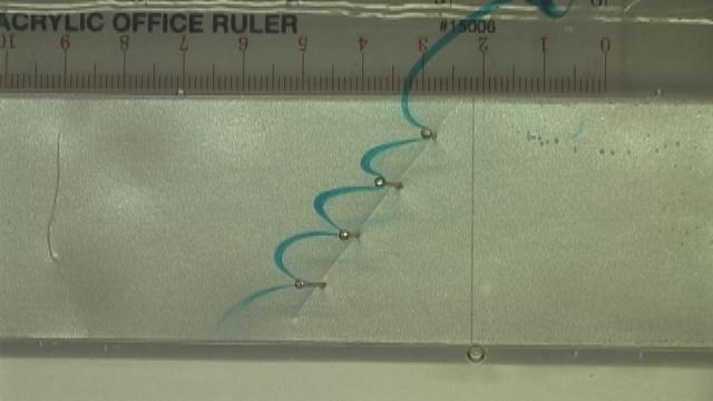
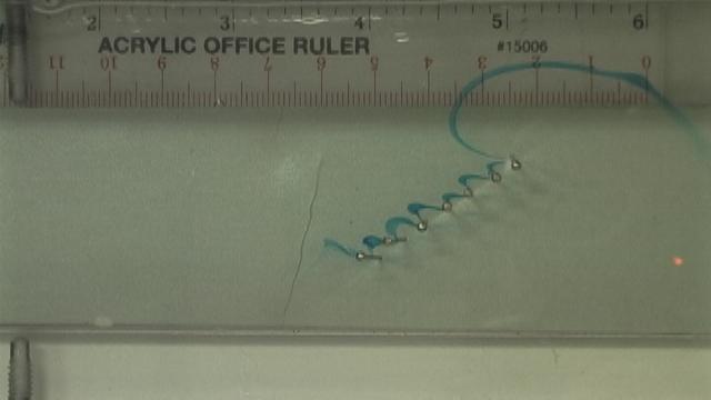
16 A. B. C. D. 16


17 E. Fig. 5. Images captured of fluid flow through the pins at different spacing and angles of attack. Each pair of images shows the initial insertion of die, parallel to the pins, while the second image is a demonstration of how the die was carried with the flow through the pins. The average Re for these images ranges from.023 to.047. The flow in each of the images is moving from right to left. At the top of the image is the free stream velocity which was used to compare to the flow through the pins. For images A) The pins have 1 cm spacing for 0 o, B) The pins have 1 cm spacing for 54 o, C) The pins have ½ cm spacing for 0 o, D) The pins have ½ cm spacing for 36 o, E) The pins have ¼ cm spacing for 27 o. The leakiness as a function of angle in degrees is plotted in Fig. 6 below. Each angle was tested setting the peristaltic pump to two different speeds in order to compare leakiness at 2 Reynolds numbers. The graph in Fig. 6 shows the plots from all three spacing at the faster speed, where the average Reynolds number for all cases was about The results we expected are verified by this graph. The 1 cm spacing allowed more flow through at a faster rate than the ½ cm and the ¼ cm spacing did. In fact, the ¼ cm spacing blocked so much flow that only the 0 o to 45 o increments were tested, because any angle higher than that would have allowed an immeasurable amount of flow. Each line on this graph represents each of the three different spacing of the pins. For all three data sets the leakiness decreases as the angle increases, as we expected to see. There is a fair amount of noise present in these graphs due to experimental error. This error could have been caused by the dye being inserted at different heights for each case. Also, it is likely that some of the pins were not 17
18 evenly spaced or standing perfectly perpendicular. There also could have been a difference with the thickness of the strip of dye inserted or the angle it was inserted at. 1.8 Leakiness Angle (Degrees) 1 cm spacing 1/2 cm spacing 1/4 cm spacing Fig. 6. Leakiness as a function of angle in 9 degree increments from 0 o to 90 o, for Re.047. For the graph in Fig. 7, leakiness is expressed as a function of angle for the ½ cm spacing for Reynolds numbers of.047 and.023. By observing this graph, one can see that a greater flow rate increases the fluid flow through the pins. It can be assumed that this representation would be the same for the bristles on an actual insect wing. These data plots show how even with the different rates of flow the leakiness consistently decreased with increased angle of the pins. The same variables of error are prevalent in this data as in Fig. 6 above, accounting for the noise in the graph. The data for 0 o and 9 o are questionable as to their accuracy. The data do not reflect what is predicted, i.e. the 0 degree plot seems too low while the 9 degree plot is too high. The margin of error in this plot was created by the specific slide chosen to measure the data. The image of 0 degrees had a very distinct pattern where the flow in the middle 18
19 pins was much less than the outer pins as demonstrated in Fig. 5C. Another factor to this error could be the amount of time that was allowed to pass in the video before capturing the image used to measure the results Leakiness /2 cm spacing speed 3 1/2 cm spacing speed Angle (Degrees) Fig. 7. Leakiness as a function of angle in 9 degree increments from 0 o to 90 o for Reynolds numbers of (speed 3) and (speed 2) for the ½ cm spacing. As can be seen in Fig. 8, leakiness varies between pins. The closer to the edge, the more flow goes through the pins. In Fig. 9, leakiness as a function of angle is shown using the measurements taken from the first pin gap rather than the middle one. We found that in many cases there was more fluid allowed through the first pair of bristles than the middle ones. Each individual graph shows a significant decrease in the leakiness as the angle increased, same as our other measurements within the margin of error. 19
 Fig. 9.")
20 Fig o degree angle with ½ cm spacing. Demonstration of the flow through the bristles being greater towards the outside of the bristles than the middle Leakiness cm spacing 1/2 cm spacing 1/4 cm spacing Angle (Degrees) Fig. 9. Leakiness as a function of angle for the angles of 0 degrees, 18 degrees and 45 degrees, for a Reynolds number of about Conclusion As mentioned before, the middle spacing of ½ cm represents the ratio between the diameter of the thrips bristle to the space between each bristle. Accordingly, the 1 cm spacing is twice as large as the spacing of the bristles in an actual thrips wing. All of the angles tested with this wing were always leaky except at really low angles of attack. With this data, having an actual wing with this ratio of spacing wouldn t work well. In the case of the ¼ cm, there 20
21 were twice as many bristles. For an actual wing perhaps this ratio isn t leaky enough at high angles of attack to be effective. The most interesting result of this study is that leakiness changes significantly with the angle of attack. These results might be of some help in the clap and fling motion because the greatest drag forces are generated when the wings are at a 90 degree angle of attack. This is also the place where the wings will leak the most. At 45 degrees, the wings act more like a solid plate. So this effect coupled with changes in leakiness due to the force acting normal to the wing could really make the wings act like leaky rakes during fling and solid plates during the rest of the stroke. Some of the problems that arose from using dye were that the placement of the dye in the stream was not always at the same height and the dye didn t always come out of the syringe in even amounts or perfectly parallel to the bristles. An improvement would be to upgrade to Digital Particle Image Velocimetry (DPIV). DPIV was originally developed to examine flows created for engineering purposes. They have proven useful over the last few years for the study of biological fluid studies as well. To use this technique the flow fluid must be injected with particles that will reflect light created by a laser. One advantage to using DPIV over the system that we used is that DPIV uses a high particle seeding density which produces a velocity vector field. The velocity vector field is so complete that there are no gaps in the field which will lead to a more precise study. 21
22 Of our experiments the models which best represented actual insect flight were the ones with the same Re and spacing. Another improvement would be to measure the forces generated by each model. For further research one idea that should be studied is to use a bigger range of Reynolds numbers. The Re for thrips flight is about 10-2, and a good study would be to see how the results changed with a different Reynolds number. When comparing the lift across Reynolds number, one must remember to compare lift coefficients rather than straight lift. 22
23 List of Symbols and Abbreviations F D F L l LEV Re U M R f R n R R 0 p drag force per unit length lift force per unit length diameter of bristle Leading Edge Vortex Reynolds Number free stream velocity of the fluid first moment of vorticity space occupied by fluid region of negative vorticity region of negligible vorticity region of positive vorticity R infinite space S space occupied by the object u(x,t) fluid velocity x=(x,y) position vector µ dynamic viscosity ρ density of the fluid ω absolute value of vorticity 23
24 References Birch, J. M., Dickson, W. B. and Dickinson, M. H. (2004). Force production and flow structure of the leading edge vortex on flapping wings at high and low Reynolds numbers. J. Exp. Biol. 207, Cheer, A. Y. L. and Koehl, M. A. R. (1987). Paddles and Rakes: fluid flow through bristled appendages of small organisms. J. Theor. Biol. 129, Ellington, C. P. (1999). The novel aerodynamics of insect flight: applications to micro-air vehicles. J. Exp. Biol. 202, Lighthill, M. J. (1973). On the Weis-Fogh mechanism of lift generation. J. Fluid Mech. 60, Miller, L. A. and Peskin, C. S. (2004). When vortices stick: an aerodynamic transition in tiny insect flight. J. Exp. Biol. 207, Miller, L. A. and Peskin, C. S. Flexible clap and fling in tiny insect flight, submitted to J. Exp. Biol. Miller, L. A. and Peskin, C. S. A computational fluid dynamics study of clap and fling in the smallest insects, submitted to J. Exp. Biol. Sun, M. and Tang, J. (2002). Unsteady aerodynamics force generation by a model fruit fly wing in flapping motion. J. Exp. Biol. 205, Sunada, S., Takashima, H., Hattori, T.,Yasuda, K. and Kiwachi, K. (2002). Fluiddynamic characteristics of a bristled wing. J. Exp. Biol. 205, Wang, Z. J. (2000). Shedding and frequency selection in flapping flight. J. Fluid Mech. 410, Weis-Fogh, T. (1973). Quick estimates of flight fitness in hovering animals, including novel mechanisms for lift production. J. Exp. Biol. 59, Weis-Fogh, T. (1975). Unusual mechanisms for the generation of lift in flying animals. Sci. Am. 233, Wu, J. C. (1981). Theory for aerodynamic force and moment in viscous flows. AIAA J. 19,
A computational fluid dynamics of clap and fling in the smallest insects
 The Journal of Experimental Biology 8, 95- Published by The Company of Biologists 5 doi:.4/jeb.376 95 A computational fluid dynamics of clap and fling in the smallest insects Laura A. Miller, * and Charles
A COMPUTATIONAL FLUID DYNAMICS STUDY OF CLAP AND FLING IN THE SMALLEST INSECTS. Laura A. Miller* and Charles S. Peskin**
 A COMPUTATIONAL FLUID DYNAMICS STUDY OF CLAP AND FLING IN THE SMALLEST INSECTS Laura A. Miller* and Charles S. Peskin** *Department of Mathematics, University of Utah, 155 South 1400 East, Salt Lake City,
Many of the smallest flying insects clap their wings together at the end of each upstroke
 DRAFT Miller, L. A. and Peskin, C. S. Title: Flexible clap and fling in tiny insect flight. Abstract Many of the smallest flying insects clap their wings together at the end of each upstroke and fling
When vortices stick: an aerodynamic transition in tiny insect flight
 The Journal of Experimental Biology 7, 7-88 Published by The Company of Biologists 4 doi:.4/jeb.8 7 When vortices stick: an aerodynamic transition in tiny insect flight Laura A. Miller* and Charles S.
Flexible clap and fling in tiny insect flight
 376 The Journal of Experimental Biology, 376-39 Published by The Company of Biologists 9 doi:./jeb.866 Flexible clap and fling in tiny insect flight Laura A. Miller* and Charles S. Peskin Department of
Unsteady aerodynamic forces of a flapping wing
 The Journal of Experimental Biology 7, 37-5 Published by The Company of Biologists 4 doi:.4/jeb.868 37 Unsteady aerodynamic forces of a flapping wing Jiang Hao Wu and Mao Sun* Institute of Fluid Mechanics,
Two-Dimensional Aerodynamic Models of Insect Flight for Robotic Flapping Wing Mechanisms of Maximum Efficiency
 Journal of Bionic Engineering 5 (2008) 1 11 Two-Dimensional Aerodynamic Models of Insect Flight for Robotic Flapping Wing Mechanisms of Maximum Efficiency Thien-Tong Nguyen 1, Doyoung Byun 2 1. Department
Computational Analysis of Hovering Hummingbird Flight
 Computational Analysis of Hovering Hummingbird Flight Zongxian Liang 1 and Haibo Dong 2 Department of Mechanical & Materials Engineering, Wright State University, Dayton, OH 45435 Mingjun Wei 3 Department
A flow control mechanism in wing flapping with stroke asymmetry during insect forward flight
 Acta Mech Sinica (2005) 21, 218 227 DOI 10.1007/s10409-005-0032-z RESEARCH PAPER Yongliang Yu Binggang Tong A flow control mechanism in wing flapping with stroke asymmetry during insect forward flight
Computational Analysis of Hovering Hummingbird Flight
 48th AIAA Aerospace Sciences Meeting Including the New Horizons Forum and Aerospace Exposition 4-7 January 2010, Orlando, Florida AIAA 2010-555 Computational Analysis of Hovering Hummingbird Flight Zongxian
NUMERICAL SIMULATION OF SELF-PROPELLED FLYING OF A THREE-DIMENSIONAL BIRD WITH FLAPPING WINGS
 NUMERICAL SIMULATION OF SELF-PROPELLED FLYING OF A THREE-DIMENSIONAL BIRD WITH FLAPPING WINGS WU Chui-Jie, ZHU Lin-Lin State Key Laboratory of Structural Analysis for Industrial Equipment, School of Aeronautics
Clap and Fling Mechanism with Interacting Porous Wings in Tiny Insect Flight
 First posted online on 4 September 2014 as 10.1242/jeb.084897 J Exp Biol Advance Access Online the most Articles. recent version First at posted http://jeb.biologists.org/lookup/doi/10.1242/jeb.084897
Smart wing rotation and ingenious leading edge vortex control modulate the unconventional forces during insects flights
 Smart wing rotation and ingenious leading edge vortex control modulate the unconventional forces during insects flights Yang Xiang, Haotian Hang, and Hong Liu J.C.Wu Center for Aerodynamics, School of
Lecture-4. Flow Past Immersed Bodies
 Lecture-4 Flow Past Immersed Bodies Learning objectives After completing this lecture, you should be able to: Identify and discuss the features of external flow Explain the fundamental characteristics
Lift Enhancement by Dynamically Changing Wingspan. in Forward Flapping Flight (09/10/2013)
") Lift Enhancement by Dynamically Changing Wingspan in Forward Flapping Flight Shizhao Wang 1, Xing Zhang 1, Guowei He 1a), ianshu Liu 2,1 (09/10/2013) 1 he State Key Laboratory of Nonlinear Mechanics, Institute
Lift Enhancement by Dynamically Changing Wingspan in Forward Flapping Flight Shizhao Wang 1, Xing Zhang 1, Guowei He 1a), ianshu Liu 2,1 (09/10/2013) 1 he State Key Laboratory of Nonlinear Mechanics, Institute
Given the water behaves as shown above, which direction will the cylinder rotate?
 water stream fixed but free to rotate Given the water behaves as shown above, which direction will the cylinder rotate? ) Clockwise 2) Counter-clockwise 3) Not enough information F y U 0 U F x V=0 V=0
Analysis of a Hinge-Connected Flapping Plate with an Implemented Torsional Spring Model
 Analysis of a Hinge-Connected Flapping Plate with an Implemented Torsional Spring Model Zach Gaston 1, Hui Wan 2 and Haibo Dong 3 Department of Mechanical & Materials Engineering, Wright State University,
FUNDAMENTAL ANALYSIS OF THREE-DIMENSIONAL NEAR FLING
 J. exp. Biol. 83, 27 248 (993) Printed in Great Britain The Company of Biologists Limited 993 27 FUNDAMENTAL ANALYSIS OF THREE-DIMENSIONAL NEAR FLING SHIGERU SUNADA Exploratory Research for Advanced Technology,
Dynamic flight stability of a hovering model insect: lateral motion
 Acta Mech Sin (010) 6:175 190 DOI 10.1007/s10409-009-00-1 RESEARCH PAPER Dynamic flight stability of a hovering model insect: lateral motion Yanlai Zhang Mao Sun Received: 18 May 009 / Revised: 5 August
SPC Aerodynamics Course Assignment Due Date Monday 28 May 2018 at 11:30
 SPC 307 - Aerodynamics Course Assignment Due Date Monday 28 May 2018 at 11:30 1. The maximum velocity at which an aircraft can cruise occurs when the thrust available with the engines operating with the
SENSITIVITY ANALYSIS OF THE FACTORS AFFECTING FORCE GENERATION BY WING FLAPPING MOTION
 Proceedings of the ASME 2013 International Mechanical Engineering Congress and Exposition IMECE2013 November 15-21, 2013, San Diego, California, USA IMECE2013-65472 SENSITIVITY ANALYSIS OF THE FACTORS
Fluid Mechanics Prof. T. I. Eldho Department of Civil Engineering Indian Institute of Technology, Bombay
 Fluid Mechanics Prof. T. I. Eldho Department of Civil Engineering Indian Institute of Technology, Bombay Lecture No. # 35 Boundary Layer Theory and Applications Welcome back to the video course on fluid
Applied Fluid Mechanics
 Applied Fluid Mechanics 1. The Nature of Fluid and the Study of Fluid Mechanics 2. Viscosity of Fluid 3. Pressure Measurement 4. Forces Due to Static Fluid 5. Buoyancy and Stability 6. Flow of Fluid and
ν δ - 1 -
 ν δ - 1 - δ ν ν δ ν ν - 2 - ρ δ ρ θ θ θ δ τ ρ θ δ δ θ δ δ δ δ τ μ δ μ δ ν δ δ δ - 3 - τ ρ δ ρ δ ρ δ δ δ δ δ δ δ δ δ δ δ - 4 - ρ μ ρ μ ρ ρ μ μ ρ - 5 - ρ τ μ τ μ ρ δ δ δ - 6 - τ ρ μ τ ρ μ ρ δ θ θ δ θ - 7
Department of Mechanical Engineering
 Department of Mechanical Engineering AMEE401 / AUTO400 Aerodynamics Instructor: Marios M. Fyrillas Email: eng.fm@fit.ac.cy HOMEWORK ASSIGNMENT #2 QUESTION 1 Clearly there are two mechanisms responsible
Visualization of flow pattern over or around immersed objects in open channel flow.
 EXPERIMENT SEVEN: FLOW VISUALIZATION AND ANALYSIS I OBJECTIVE OF THE EXPERIMENT: Visualization of flow pattern over or around immersed objects in open channel flow. II THEORY AND EQUATION: Open channel:
Clap and fling mechanism with interacting porous wings in tiny insect flight
 14. Published by The Company of iologists Ltd (14) 17, 3898-399 doi:1.14/jeb.84897 RESERCH RTICLE Clap and fling mechanism with interacting porous wings in tiny insect flight rvind Santhanakrishnan 1,
Title: Aerodynamics characteristics of butterfly flight through measurement of threedimensional unsteady velocity field using TR-PIV system
 Title: Aerodynamics characteristics of butterfly flight through measurement of threedimensional unsteady velocity field using TR-PIV system REF: AOARD-09-4102 Contract No. FA23860914102 PI: Debopam Das
τ du In his lecture we shall look at how the forces due to momentum changes on the fluid and viscous forces compare and what changes take place.
 4. Real fluids The flow of real fluids exhibits viscous effect, that is they tend to stick to solid surfaces and have stresses within their body. You might remember from earlier in the course Newtons law
CENG 501 Examination Problem: Estimation of Viscosity with a Falling - Cylinder Viscometer
 CENG 501 Examination Problem: Estimation of Viscosity with a Falling - Cylinder Viscometer You are assigned to design a fallingcylinder viscometer to measure the viscosity of Newtonian liquids. A schematic
Numerical Analysis of Unsteady Viscous Flow through a Weis-Fogh-Type Water Turbine
 International Conference on Emerging Trends in Computer and Image Processing (ICETCIP'014) Dec. 15-16, 014 Pattaya (Thailand) Numerical Analysis of Unsteady Viscous Flow through a Weis-Fogh-Type Water
RESEARCH ARTICLE Aerodynamic effects of corrugation in flapping insect wings in hovering flight
 3 The Journal of Experimental iology, 3-. Published by The Company of iologists Ltd doi:./jeb.6375 RESERCH RTIE erodynamic effects of corrugation in flapping insect wings in hovering flight Xue Guang Meng*,
φ(r, θ, t) = a 2 U(t) cos θ. (7.1)
 = a 2 U(t) cos θ. (7.1)") BioFluids Lectures 7-8: Slender Fish Added Mass for Lateral Motion At high Reynolds number, most of the effort required in swimming is pushing water out of the way, that is our energy goes in providing
BioFluids Lectures 7-8: Slender Fish Added Mass for Lateral Motion At high Reynolds number, most of the effort required in swimming is pushing water out of the way, that is our energy goes in providing
Lift and power requirements of hovering flight in Drosophila virilis
 The Journal of Experimental Biology 5, 37 () Printed in Great Britain The ompany of Biologists Limited JEB6 3 Lift and power requirements of hovering flight in Drosophila virilis Mao Sun* and Jian Tang
Figure 3: Problem 7. (a) 0.9 m (b) 1.8 m (c) 2.7 m (d) 3.6 m
 0.9 m (b) 1.8 m (c) 2.7 m (d) 3.6 m") 1. For the manometer shown in figure 1, if the absolute pressure at point A is 1.013 10 5 Pa, the absolute pressure at point B is (ρ water =10 3 kg/m 3, ρ Hg =13.56 10 3 kg/m 3, ρ oil = 800kg/m 3 ): (a)
1. For the manometer shown in figure 1, if the absolute pressure at point A is 1.013 10 5 Pa, the absolute pressure at point B is (ρ water =10 3 kg/m 3, ρ Hg =13.56 10 3 kg/m 3, ρ oil = 800kg/m 3 ): (a)
1. Fluid Dynamics Around Airfoils
 1. Fluid Dynamics Around Airfoils Two-dimensional flow around a streamlined shape Foces on an airfoil Distribution of pressue coefficient over an airfoil The variation of the lift coefficient with the
Wing Kinematics in a Hovering Dronefly Minimize Power Expenditure
 Wing Kinematics in a Hovering Dronefly Minimize Power Expenditure Authors: J. H. Wu, and M. Sun Source: Journal of Insect Science, 14(159) : 1-8 Published By: Entomological Society of America URL: https://doi.org/10.1093/jisesa/ieu021
Mestrado Integrado em Engenharia Mecânica Aerodynamics 1 st Semester 2012/13
 Mestrado Integrado em Engenharia Mecânica Aerodynamics 1 st Semester 212/13 Exam 2ª época, 2 February 213 Name : Time : 8: Number: Duration : 3 hours 1 st Part : No textbooks/notes allowed 2 nd Part :
External Forced Convection. Copyright The McGraw-Hill Companies, Inc. Permission required for reproduction or display.
 External Forced Convection Copyright The McGraw-Hill Companies, Inc. Permission required for reproduction or display. Drag and Heat Transfer in External flow Fluid flow over solid bodies is responsible
Optimization of Flapping Airfoils for Maximum Thrust and Propulsive Efficiency I. H. Tuncer, M. Kay
 Czech Technical University in Prague Acta Polytechnica Vol. 44 No. 1/2004 Optimization of Flapping Airfoils for Maximum Thrust and Propulsive Efficiency I. H. Tuncer, M. Kay A numerical optimization algorithm
A Biologically Inspired Computational Study of Flow Past Tandem Flapping Foils
 A Biologically Inspired Computational Study of Flow Past andem Flapping Foils I. Akhtar * and R. Mittal Department of Mechanical & Aerospace Engineering he George Washington University, Washington DC 20052
PIV and force measurements on the flapping-wing MAV DelFly II
 Master of Science Thesis PIV and force measurements on the flapping-wing MAV DelFly II An aerodynamic and aeroelastic investigation into vortex development M.A. Groen 2 December 21 Ad Faculty of Aerospace
Aerodynamic force analysis in high Reynolds number flows by Lamb vector integration
 Aerodynamic force analysis in high Reynolds number flows by Lamb vector integration Claudio Marongiu, Renato Tognaccini 2 CIRA, Italian Center for Aerospace Research, Capua (CE), Italy E-mail: c.marongiu@cira.it
We are IntechOpen, the world s leading publisher of Open Access books Built by scientists, for scientists. International authors and editors
 We are IntechOpen, the world s leading publisher of Open Access books Built by scientists, for scientists 3,800 116,000 120M Open access books available International authors and editors Downloads Our
Scaling Law I. BioSensing & BioMEMS 530/ Jeff Wang Johns Hopkins University 1
 Scaling Law I Jeff Wang Johns Hopkins University 1 Why scaling is important at the micro and nano scale Micro and nano devices are orders of magnitude smaller than macro counterparts As the sizes shrink,
Introduction to Aerospace Engineering
 4. Basic Fluid (Aero) Dynamics Introduction to Aerospace Engineering Here, we will try and look at a few basic ideas from the complicated field of fluid dynamics. The general area includes studies of incompressible,
Fundamentals of Fluid Dynamics: Ideal Flow Theory & Basic Aerodynamics
 Fundamentals of Fluid Dynamics: Ideal Flow Theory & Basic Aerodynamics Introductory Course on Multiphysics Modelling TOMASZ G. ZIELIŃSKI (after: D.J. ACHESON s Elementary Fluid Dynamics ) bluebox.ippt.pan.pl/
Lecture 7 Boundary Layer
 SPC 307 Introduction to Aerodynamics Lecture 7 Boundary Layer April 9, 2017 Sep. 18, 2016 1 Character of the steady, viscous flow past a flat plate parallel to the upstream velocity Inertia force = ma
The Interaction of Wings in Different Flight Modes of a Dragonfly
 The Interaction of Wings in Different Flight Modes of a Dragonfly Csaba Hefler 1, Huihe Qiu 1,*, Wei Shyy 1 1: Department of Mechanical and Aerospace Engineering, The Hong Kong University of Science and
Active Control of Separated Cascade Flow
 Chapter 5 Active Control of Separated Cascade Flow In this chapter, the possibility of active control using a synthetic jet applied to an unconventional axial stator-rotor arrangement is investigated.
(This is a sample cover image for this issue. The actual cover is not yet available at this time.)
") (This is a sample cover image for this issue. The actual cover is not yet available at this time.) This is an open access article which appeared in a ournal published by Elsevier. This article is free
(This is a sample cover image for this issue. The actual cover is not yet available at this time.) This is an open access article which appeared in a ournal published by Elsevier. This article is free
Detailed Outline, M E 320 Fluid Flow, Spring Semester 2015
 Detailed Outline, M E 320 Fluid Flow, Spring Semester 2015 I. Introduction (Chapters 1 and 2) A. What is Fluid Mechanics? 1. What is a fluid? 2. What is mechanics? B. Classification of Fluid Flows 1. Viscous
AEROSPACE ENGINEERING DEPARTMENT. Second Year - Second Term ( ) Fluid Mechanics & Gas Dynamics
 Fluid Mechanics & Gas Dynamics") AEROSPACE ENGINEERING DEPARTMENT Second Year - Second Term (2008-2009) Fluid Mechanics & Gas Dynamics Similitude,Dimensional Analysis &Modeling (1) [7.2R*] Some common variables in fluid mechanics include:
AEROSPACE ENGINEERING DEPARTMENT Second Year - Second Term (2008-2009) Fluid Mechanics & Gas Dynamics Similitude,Dimensional Analysis &Modeling (1) [7.2R*] Some common variables in fluid mechanics include:
/ m U) β - r dr/dt=(n β / C) β+ (N r /C) r [8+8] (c) Effective angle of attack. [4+6+6]
![/ m U) β - r dr/dt=(n β / C) β+ (N r /C) r [8+8] (c) Effective angle of attack. [4+6+6]](/thumbs/91/105418625.jpg "/ m U) β - r dr/dt=(n β / C) β+ (N r /C) r [8+8] (c) Effective angle of attack. [4+6+6]") Code No: R05322101 Set No. 1 1. (a) Explain the following terms with examples i. Stability ii. Equilibrium. (b) Comment upon the requirements of stability of a i. Military fighter aircraft ii. Commercial
Code No: R05322101 Set No. 1 1. (a) Explain the following terms with examples i. Stability ii. Equilibrium. (b) Comment upon the requirements of stability of a i. Military fighter aircraft ii. Commercial
UNIT II Real fluids. FMM / KRG / MECH / NPRCET Page 78. Laminar and turbulent flow
 UNIT II Real fluids The flow of real fluids exhibits viscous effect that is they tend to "stick" to solid surfaces and have stresses within their body. You might remember from earlier in the course Newtons
Numerical Investigation of Thermal Performance in Cross Flow Around Square Array of Circular Cylinders
 Numerical Investigation of Thermal Performance in Cross Flow Around Square Array of Circular Cylinders A. Jugal M. Panchal, B. A M Lakdawala 2 A. M. Tech student, Mechanical Engineering Department, Institute
Day 24: Flow around objects
 Day 24: Flow around objects case 1) fluid flowing around a fixed object (e.g. bridge pier) case 2) object travelling within a fluid (cars, ships planes) two forces are exerted between the fluid and the
Effects of unsteady deformation of flapping wing on its aerodynamic forces
 Appl. Math. Mech. -Engl. Ed., 2008, 29(6):731 743 DOI 10.1007/s10483-008-0605-9 c Editorial Committee of Appl. Math. Mech. and Springer-Verlag 2008 Applied Mathematics and Mechanics (English Edition) Effects
Experimental characterization of flow field around a square prism with a small triangular prism
 Journal of Mechanical Science and Technology 29 (4) (2015) 1649~1656 www.springerlink.com/content/1738-494x OI 10.1007/s12206-015-0336-2 Experimental characterization of flow field around a square prism
The wings and the body shape of Manduca sexta and Agrius convolvuli are compared in
 1 Wing and body shape of Manduca sexta and Agrius convolvuli The wings and the body shape of Manduca sexta and Agrius convolvuli are compared in terms of the aspect ratio of forewing AR fw (wing length
CLAP AND FLING AERODYNAMICS - AN EXPERIMENTAL EVALUATION
 J. exp. Biol. (i977). 69, 261-273 26l With 8 figures 'tinted in Great Britain CLAP AND FLING AERODYNAMICS - AN EXPERIMENTAL EVALUATION BY LEON BENNETT Department of Applied Science, New York University,
Lifting Airfoils in Incompressible Irrotational Flow. AA210b Lecture 3 January 13, AA210b - Fundamentals of Compressible Flow II 1
 Lifting Airfoils in Incompressible Irrotational Flow AA21b Lecture 3 January 13, 28 AA21b - Fundamentals of Compressible Flow II 1 Governing Equations For an incompressible fluid, the continuity equation
Nicholas J. Giordano. Chapter 10 Fluids
 Nicholas J. Giordano www.cengage.com/physics/giordano Chapter 10 Fluids Fluids A fluid may be either a liquid or a gas Some characteristics of a fluid Flows from one place to another Shape varies according
REE Internal Fluid Flow Sheet 2 - Solution Fundamentals of Fluid Mechanics
 REE 307 - Internal Fluid Flow Sheet 2 - Solution Fundamentals of Fluid Mechanics 1. Is the following flows physically possible, that is, satisfy the continuity equation? Substitute the expressions for
On Calculation of Hydrodynamic Forces for Steady Flows in Unbounded Domains
 On Calculation of Hydrodynamic Forces for Steady Flows in Unbounded Domains B. Protas Department of Mathematics & Statistics, McMaster University, Hamilton, ON, Canada Abstract This note addresses the
Fig. 1. Bending-Torsion Foil Flutter
 27 TH INTERNATIONAL CONGRESS OF THE AERONAUTICAL SCIENCES EXTRACTING POWER IN JET STREAMS: PUSHING THE PERFORMANCE OF FLAPPING WING TECHNOLOGY M.F. Platzer*, M.A. Ashraf**, J. Young**, and J.C.S. Lai**
Fluid Mechanics. du dy
 FLUID MECHANICS Technical English - I 1 th week Fluid Mechanics FLUID STATICS FLUID DYNAMICS Fluid Statics or Hydrostatics is the study of fluids at rest. The main equation required for this is Newton's
Friction Factors and Drag Coefficients
 Levicky 1 Friction Factors and Drag Coefficients Several equations that we have seen have included terms to represent dissipation of energy due to the viscous nature of fluid flow. For example, in the
Department of Energy Sciences, LTH
 Department of Energy Sciences, LTH MMV11 Fluid Mechanics LABORATION 1 Flow Around Bodies OBJECTIVES (1) To understand how body shape and surface finish influence the flow-related forces () To understand
Introduction to Turbulence AEEM Why study turbulent flows?
 Introduction to Turbulence AEEM 7063-003 Dr. Peter J. Disimile UC-FEST Department of Aerospace Engineering Peter.disimile@uc.edu Intro to Turbulence: C1A Why 1 Most flows encountered in engineering and
SIMULATION OF GAS FLOW OVER MICRO-SCALE AIRFOILS USING A HYBRID CONTINUUM-PARTICLE APPROACH
 33rd AIAA Fluid Dynamics Conference and Exhibit 3-6 June 3, Orlando, Florida AIAA 3-44 33 rd AIAA Fluid Dynamics Conference and Exhibit / Orlando, Florida / 3-6 Jun 3 SIMULATION OF GAS FLOW OVER MICRO-SCALE
Vortex Dynamics in Near Wake of a Hovering Hawkmoth
 46th AIAA Aerospace Sciences Meeting and Exhibit 7-1 January 28, Reno, Nevada AIAA 28-583 Vortex Dynamics in Near Wake of a Hovering Hawkmoth Hikaru Aono 1 Graduate School of Science and Technology, Chiba
Numerical study of battle damaged two-dimensional wings
 Advances in Fluid Mechanics IX 141 Numerical study of battle damaged two-dimensional wings S. Djellal, T. Azzam, M. Djellab & K. Lakkaichi Fluid Mechanics Laboratory Polytechnical School Bordj El Bahri,
Side-View Mirror Vibrations Induced Aerodynamically by Separating Vortices
 Open Journal of Fluid Dynamics, 2016, 6, 42-56 Published Online March 2016 in SciRes. http://www.scirp.org/journal/ojfd http://dx.doi.org/10.4236/ojfd.2016.61004 Side-View Mirror Vibrations Induced Aerodynamically
K. M. Isaac, P. Shivaram + University of Missouri-Rolla Rolla, MO T. DalBello NASA Glenn Research Center
 Low Re, High α Aerodynamics with Controlled Wing Kinematics K. M. Isaac, P. Shivaram + University of Missouri-Rolla Rolla, MO 65409 isaac@umr.edu T. DalBello NASA Glenn Research Center ABSTRACT Numerical
The E80 Wind Tunnel Experiment the experience will blow you away. by Professor Duron Spring 2012
 The E80 Wind Tunnel Experiment the experience will blow you away by Professor Duron Spring 2012 Objectives To familiarize the student with the basic operation and instrumentation of the HMC wind tunnel
Chapter 7: External Forced Convection
 Chapter 7: External Forced Convection Yoav Peles Department of Mechanical, Aerospace and Nuclear Engineering Rensselaer Polytechnic Institute Copyright The McGraw-Hill Companies, Inc. Permission required
Force production and flow structure of the leading edge vortex on flapping wings at high and low Reynolds numbers
 The Journal of Experimental iology 27, 163-172 Published by The Company of iologists 24 doi:1.1242/jeb.848 163 Force production and flow structure of the leading edge vortex on flapping wings at high and
ScienceDirect. Experimental Validation on Lift Increment of a Flapping Rotary Wing with Boring-hole Design
 Available online at www.sciencedirect.com ScienceDirect Procedia Engineering 99 (2015 ) 1543 1547 APISAT2014, 2014 Asia-Pacific International Symposium on Aerospace Technology, APISAT2014 Experimental
COMPUTATIONAL SIMULATION OF THE FLOW PAST AN AIRFOIL FOR AN UNMANNED AERIAL VEHICLE
 COMPUTATIONAL SIMULATION OF THE FLOW PAST AN AIRFOIL FOR AN UNMANNED AERIAL VEHICLE L. Velázquez-Araque 1 and J. Nožička 2 1 Division of Thermal fluids, Department of Mechanical Engineering, National University
ABSTRACT PARAMETRIC INVESTIGATIONS INTO FLUID-STRUCTURE INTERACTIONS IN HOVERING FLAPPING FLIGHT. Jesse Maxwell, 2013
 ABSTRACT Title of Thesis: PARAMETRIC INVESTIGATIONS INTO FLUID-STRUCTURE INTERACTIONS IN HOVERING FLAPPING FLIGHT Jesse Maxwell, 2013 Thesis Directed By: Professor Balakumar Balachandran Department of
10.52 Mechanics of Fluids Spring 2006 Problem Set 3
 10.52 Mechanics of Fluids Spring 2006 Problem Set 3 Problem 1 Mass transfer studies involving the transport of a solute from a gas to a liquid often involve the use of a laminar jet of liquid. The situation
Aeroelastic Analysis Of Membrane Wings
 Aeroelastic Analysis Of Membrane Wings Soumitra P. Banerjee and Mayuresh J. Patil Virginia Polytechnic Institute and State University, Blacksburg, Virginia 46-3 The physics of flapping is very important
MATH 566: FINAL PROJECT
 MATH 566: FINAL PROJECT December, 010 JAN E.M. FEYS Complex analysis is a standard part of any math curriculum. Less known is the intense connection between the pure complex analysis and fluid dynamics.
STUDY OF FLOW & HEAT TRANSFER IN PLATE FIN HEAT EXCHANGER AT VARYING REYNOLD S NO
 STUDY OF FLOW & HEAT TRANSFER IN PLATE FIN HEAT EXCHANGER AT VARYING REYNOLD S NO Pardeep Yadav 1, Pawan Kumar 1, Bhupender Singh 2 1 DAV College of Engg.& Technology,Kanina,(M.Garh) HR 2 YMCA University
2 Navier-Stokes Equations
 1 Integral analysis 1. Water enters a pipe bend horizontally with a uniform velocity, u 1 = 5 m/s. The pipe is bended at 90 so that the water leaves it vertically downwards. The input diameter d 1 = 0.1
DISSECTING INSECT FLIGHT
 Annu. Rev. Fluid Mech. 2005. 37:183 210 doi: 10.1146/annurev.fluid.36.050802.121940 Copyright c 2005 by Annual Reviews. All rights reserved DISSECTING INSECT FLIGHT Z. Jane Wang Theoretical and Applied
Applied Thermal and Fluid Engineering. Energy Engineering (Thermal Engineering Laboratory)
") Applied Thermal and Fluid Engineering Energy Engineering (Thermal Engineering Laboratory) Professor Assoc. Professor Hajime Nakamura Shunsuke Yamada Outline of Research In our laboratory, we have been
Applied Thermal and Fluid Engineering Energy Engineering (Thermal Engineering Laboratory) Professor Assoc. Professor Hajime Nakamura Shunsuke Yamada Outline of Research In our laboratory, we have been
Math 575-Lecture Failure of ideal fluid; Vanishing viscosity. 1.1 Drawbacks of ideal fluids. 1.2 vanishing viscosity
 Math 575-Lecture 12 In this lecture, we investigate why the ideal fluid is not suitable sometimes; try to explain why the negative circulation appears in the airfoil and introduce the vortical wake to
Bluff Body, Viscous Flow Characteristics ( Immersed Bodies)
") Bluff Body, Viscous Flow Characteristics ( Immersed Bodies) In general, a body immersed in a flow will experience both externally applied forces and moments as a result of the flow about its external surfaces.
Bluff Body, Viscous Flow Characteristics ( Immersed Bodies) In general, a body immersed in a flow will experience both externally applied forces and moments as a result of the flow about its external surfaces.
THE CONTROL OF FLIGHT FORCE BY A FLAPPING WING: LIFT AND DRAG PRODUCTION
 The Journal of Experimental Biology 24, 2672626 (2) Printed in Great Britain The Company of Biologists Limited 2 JEB34 267 THE CONTROL OF FLIGHT FORCE BY A FLAPPING WING: LIFT AND DRAG PRODUCTION SANJAY
SHAPE, FLAPPING AND FLEXION: WING AND FIN DESIGN FOR FORWARD FLIGHT
 The Journal of Experimental Biology 4, 73 85 () Printed in Great Britain The Company of Biologists Limited JEB37 73 SHAPE, FLAPPING AND FLEXION: WING AND FIN DESIGN FOR FORWARD FLIGHT S. A. COMBES* AND
Relationship between Unsteady Fluid Force and Vortex Behavior around a Discoid Airfoil Simulating a Hand of Swimmer
 45 * Relationship between Unsteady Fluid Force and Vortex Behavior around a Discoid Airfoil Simulating a Hand of Swimmer Hiroaki HASEGAWA, Department of Mechanical Engineering, Akita University Jun WATANABE,
2 D.D. Joseph To make things simple, consider flow in two dimensions over a body obeying the equations ρ ρ v = 0;
 Accepted for publication in J. Fluid Mech. 1 Viscous Potential Flow By D.D. Joseph Department of Aerospace Engineering and Mechanics, University of Minnesota, MN 55455 USA Email: joseph@aem.umn.edu (Received
ME332 FLUID MECHANICS LABORATORY (PART I)
") ME332 FLUID MECHANICS LABORATORY (PART I) Mihir Sen Department of Aerospace and Mechanical Engineering University of Notre Dame Notre Dame, IN 46556 Version: January 14, 2002 Contents Unit 1: Hydrostatics
ME332 FLUID MECHANICS LABORATORY (PART I) Mihir Sen Department of Aerospace and Mechanical Engineering University of Notre Dame Notre Dame, IN 46556 Version: January 14, 2002 Contents Unit 1: Hydrostatics
High Speed Aerodynamics. Copyright 2009 Narayanan Komerath
 Welcome to High Speed Aerodynamics 1 Lift, drag and pitching moment? Linearized Potential Flow Transformations Compressible Boundary Layer WHAT IS HIGH SPEED AERODYNAMICS? Airfoil section? Thin airfoil
Empirical Determination of Aerodynamic Coefficients of. a Micro-robotic Dragonfly s Wings
 Empirical Determination of Aerodynamic Coefficients of a Micro-robotic Dragonfly s Wings Submitted to Undergraduate Awards Engineering and Mechanical Sciences Category June 2014 Abstract The present study
Dynamic flight stability of a hovering bumblebee
 The Journal of Experimental iology 28, 447-459 Published by The Company of iologists 25 doi:1.1242/jeb.147 447 Dynamic flight stability of a hovering bumblebee Mao Sun* and Yan Xiong Institute of Fluid
COURSE ON VEHICLE AERODYNAMICS Prof. Tamás Lajos University of Rome La Sapienza 1999
 COURSE ON VEHICLE AERODYNAMICS Prof. Tamás Lajos University of Rome La Sapienza 1999 1. Introduction Subject of the course: basics of vehicle aerodynamics ground vehicle aerodynamics examples in car, bus,
Analysis of transitions between fluttering, tumbling and steady descent of falling cards
 J. Fluid Mech. (25), vol. 541, pp. 91 14. c 25 Cambridge University Press doi:1.117/s2211255847 Printed in the United Kingdom 91 Analysis of transitions between fluttering, tumbling and steady descent