TurfWeather Weather Station
|
|
|
- Bertram Rose
- 6 years ago
- Views:
Transcription


1 Revision: 5/11 Copyright Campbell Scientific, Inc.
 to be free from defects in materials and workmanship under normal use and service for twelve (12) months from date of shipment unless specified otherwise. ***** Batteries are not warranted.")
2 WARRANTY AND ASSISTANCE This equipment is warranted by CAMPBELL SCIENTIFIC (CANADA) CORP. ( CSC ) to be free from defects in materials and workmanship under normal use and service for twelve (12) months from date of shipment unless specified otherwise. ***** Batteries are not warranted. ***** CSC's obligation under this warranty is limited to repairing or replacing (at CSC's option) defective products. The customer shall assume all costs of removing, reinstalling, and shipping defective products to CSC. CSC will return such products by surface carrier prepaid. This warranty shall not apply to any CSC products which have been subjected to modification, misuse, neglect, accidents of nature, or shipping damage. This warranty is in lieu of all other warranties, expressed or implied, including warranties of merchantability or fitness for a particular purpose. CSC is not liable for special, indirect, incidental, or consequential damages. Products may not be returned without prior authorization. To obtain a Return Merchandise Authorization (RMA), contact CAMPBELL SCIENTIFIC (CANADA) CORP., at (780) An RMA number will be issued in order to facilitate Repair Personnel in identifying an instrument upon arrival. Please write this number clearly on the outside of the shipping container. Include description of symptoms and all pertinent details. CAMPBELL SCIENTIFIC (CANADA) CORP. does not accept collect calls. Non-warranty products returned for repair should be accompanied by a purchase order to cover repair costs.
3 PLEASE READ FIRST About this manual Please note that this manual was originally produced by Campbell Scientific Inc. (CSI) primarily for the US market. Some spellings, weights and measures may reflect this origin. Some useful conversion factors: Area: 1 in 2 (square inch) = 645 mm 2 Length: Mass: Pressure: Volume: 1 in. (inch) = 25.4 mm 1 ft (foot) = mm 1 yard = m 1 mile = km 1 oz. (ounce) = g 1 lb (pound weight) = kg 1 psi (lb/in2) = mb 1 US gallon = litres In addition, part ordering numbers may vary. For example, the CABLE5CBL is a CSI part number and known as a FIN5COND at Campbell Scientific Canada (CSC). CSC Technical Support will be pleased to assist with any questions.
4 TurfWeather Table of Contents PDF viewers note: These page numbers refer to the printed version of this document. Use the Adobe Acrobat bookmarks tab for links to specific sections. 1. Quick Start Guide Computer Requirements TurfWeather Setup Procedure Radio Setup Help and Support Installation Power Sources Site Selection Communications Considerations Direct Communications Cable Lengths Grounding Issues Wireless Communications Transmission Ranges Line-of-Sight Testing Radio Transmissions Installation Procedures Tripod Installation Procedures Procedure 1a: Tripod Preparation for Installation Procedure 1b: Ground Installations Procedure 2: Guy-Wire Kit Installation Procedure 3: Mounting the TurfWeather Station on a Tripod or Pole Procedure 4: SP5 Solar Panel Installation Procedure 5: Ground Kit Installation Procedure 6: Base Radio and standard antenna installation Procedure 7: Short-Haul Modem installation Maintenance Solar Panel P/N SP Battery Pack P/N Temperature/Relative Humidity sensor P/N Solar Radiation sensor P/N Rain Gauge P/N Wind Speed Sensor P/N Wind Direction Sensor P/N Memory Battery P/N Auxiliary Battery Unit Installation Procedure High Gain Base Station Antenna Installation Procedure Battery Pack (P/N 14159) Removal and Replacement Procedure Temperature/Relative Humidity Sensor Assembly (P/N 14144) Removal and Replacement Procedure...46 i
5 TurfWeather Table of Contents Appendix 3.13 Solar Radiation Sensor (P/N 14009) Removal and Replacement Procedure Rain Gauge (P/N 25585) Removal and Replacement Procedure Wind Speed Sensor (Anemometer) (P/N 14010) Removal and Replacement Procedure Wind Direction Sensor (P/N 14011) Removal and Replacement Procedure Memory Battery (P/N 15598) Removal and Replacement Procedure Main Electronics Board (Motherboard) Removal and Replacement Procedure Spread Spectrum Radio (all frequencies) Removal and Replacement Procedure A. TurfWeather Equipment... A-1 A.1 Communications Options... A-1 A Serial-to-USB Adapter... A-1 A.2 Power Supplies... A-1 A W Solar Panel Kit... A-1 A AC Converter... A-2 A.3 Mounting/Installation Kits... A-3 A Tripod/Mast Assembly... A-3 A Tripod Installation Kit... A-3 A Tripod Stake Kit... A-4 A Tripod Mast Extension... A-4 A Tripod Guy-wire Kit... A-5 A Tripod Grounding Kit... A-6 Figures 1-1. Box of standard and wireless equipment. The lift straps allow easy removal of the weather station from the box Serial cable (left) and the weather station serial port in which the serial cable male connector connects. A dust cover must be removed from the weather station RS-232 port before connecting the cable Keyed power switch is located on the bottom of the weather station The radio antenna may be a surface mount antenna (left), a whip antenna(right) that connects directly to the radio, or other optional antennas (not shown) The connector marked Antenna on an RF401-series radio is where the antennas attach Radio connections. The serial cable (left) connects to the port marked RS232 and the AC adapter connects to the port marked DC Pwr input Ten Times the Height Rule. If the height of the tree, T, is 8 feet and the height of the shed, H, is 7 ft then the weather station should be placed at least 80 ft away from the tree (i.e., 10T = 10x8 =80 ft) and 70 ft away from the shed (i.e., 10H = 10x7 = 70 ft) ii
6 TurfWeather Table of Contents 2-2. Line-of-sight examples. As the dotted line indicates, Station 1 has a clear line-of-sight with the Computer Site. The mountain obstructs Station 2 s line-of-sight and would reduce or possibly prevent wireless communications The Tripod Kit includes the nut and bolt (left) used to attach each foot to the tripod Pound the tapered end of the mast extension (left) into the tripod mast. If using two extensions, pound the tapered end of the second extension into the top of the first extension The mast fits in the center of the tripod. The mast height is adjusted by moving the tripod legs or removing the mast cup and sliding the mast up or down in the collars For temporary sites, drive the stakes of the Tripod Stake Kit (left) through the center hole in each tripod foot (right). The stakes should be driven in until they barely contact the foot surface. For permanent sites, install user-supplied bolts through the holes in each tripod foot The TurfWeather weather station assembly properly seated on a mast or pole Two views of the TurfWeather station. The U-bolt and nuts are shown Accurate wind direction measurements require the reference line on the wind direction sensor (right) to be aligned with Magnetic North The bubble level (in red box) confirms the station is level, which is required for accurate rainfall and solar radiation measurements The red or green cap protects the solar radiation sensor while the weather station is being shipped and installed. Accurate measurements require the cap to be removed The ground lug connected to the bottom of the weather station The right close up is the 14 AWG wire and the #4 cable attached to the tripod coupling The #4 cable connected to the ground rod The Base RF401 and RF416 installation The Short Haul Enclosure Mounted The Cables Connected to Enclosure The Cables Connected to Weather Station...33 iii
7 TurfWeather Table of Contents iv
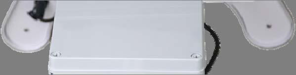
 Lift Straps FIGURE 1-1. Box of standard and wireless equipment.")
8 1. Quick Start Guide 1.1 Computer Requirements Windows 2000, XP, Vista, or Windows 7 Operating System. Available Serial Port or USB Port (Serial-to-USB Converter Cable required) Lift Straps FIGURE 1-1. Box of standard and wireless equipment. The lift straps allow easy removal of the weather station from the box. 1.2 TurfWeather Setup Procedure 1. Remove the top foam packing from the TurfWeather weather station box and verify you have all ordered equipment (see Equipment List). 2. Unpack equipment. CAUTION a. Use the lift straps to remove the weather station, since removing the station by lifting on the sensors may damage the sensors (see Figure 1-1). b. Avoid resting the weather station on the wind speed and wind direction sensors. c. Report missing or damaged equipment to Campbell Scientific Customer Service before installing your system. 1
. FIGURE 1-2.")

9 3. Install the Campbell Scientific PC200W Software on your computer. 4. Connect the serial cable male connector to the weather station RS-232 port and the serial cable female connector to a computer serial port (Figure 1-2). FIGURE 1-2. Serial cable (left) and the weather station serial port in which the serial cable male connector connects. A dust cover must be removed from the weather station RS-232 port before connecting the cable. NOTE a. Ensure the computer serial port is not already assigned to an open program. b. If you re connecting the cable to a USB port, a serial-to-usb converter cable is required and optionally available from Campbell Scientific P/N 16878,USB-AD. NOTE If the TurfWeather station has been configured for use with the optional external battery back, no internal battery is inside of the weather station. The station must be powered from the external battery unit prior to turning on the key in step 5. To do this, the cable (P/N 18971) should be connected to the AUXILIARY connector on the bottom of the TurfWeather station and to the external battery unit. Refer to Section 3.9 of the manual, but note that the internal battery has already been removed. 5. Turn the key to the on position (Figure 1-3). This is the power on/off switch for the weather station. The weather station will be running on battery power only at this point. Remember to turn this switch off whenever possible when the charging cable is not connected to prevent damaging the battery. 2


10 FIGURE 1-3. Keyed power switch is located on the bottom of the weather station. 6. Load and start the Campbell Scientific PC200W software. 7. The first time PC200W opens, it will open with the EZSetup Wizard or it can be accessed by clicking on the add button. It is the green + in the top left area of the main screen. 8. Click on the Next button on the Introduction window. 3

11 9. Select CR200Series from the drop down menu in the Datalogger Type and Name window. Highlight the CR200Series under the Datalogger Name and rename it TurfWeather. Click Next. 4

12 10. Select the COM Port used to connect to the weather station from the COM Port drop down box. Leave the COM Port Communication Delay set to 00 seconds, and click Next. 5

13 11. Select 9600 from the Baud Rate drop down box, the PakBus Address 1, and the Extra Response Time 00 and then click Next. 6

14 12. This will be the Communication Setup Summary, click on Next. If changes need to be made, then click on Previous to go to the Correct window to make changes. Then click on Next to advance back to the Setup Summary. 7

15 13. This will be the Communication Test window. With Yes selected, click on Next. 8

16 14. Communication Test Succeeded window will inform you after table definitions have been updated. This may take several minuets. Click Next. 9

17 15. The Datalogger Clock window will display the PC clock and the Datalogger clock. Click on the Set Datalogger Clock to sync the Datalogger date and time with the PC if needed then click Next. 10

18 16. The Datalogger Program window will display the current program. Verify the correct program for application is shown as Current Program. Click Next. 11

19 17. The Wizard Complete window is now displayed. Click on Finish This will bring you to the main PC200W window 18. From this Main Screen, click on the Monitor Data tab at the top. 12

20 19. This screen will display the measurements from the TurfWeather weather station. The weather station is communicating and making measurements if the screen readings being displayed look accurate and are updating. 20. Click on Disconnect. PC200W can also be used to verify communication with radios after setting them up using the following instructions. 21. Proceed to Radio Setup (Section 1.3) if using radio communication. If the TurfWeather weather station is a direct connect, Turn off key switch on weather station and proceed to the TurfWeather Site Installation Guide. NOTE If the weather station does not function properly, contact your local distributor to solve the problem before continuing to the next steps. 13
.")
, a whip antenna(right) that connects")
21 1.3 Radio Setup 1. Attach the antenna or cable to the radio connector marked Antenna (Figures 1-4 and 1-5). FIGURE 1-4. The radio antenna may be a surface mount antenna (left), a whip antenna(right) that connects directly to the radio, or other optional antennas (not shown). FIGURE 1-5. The connector marked Antenna on an RF401-series radio is where the antennas attach. 14
 connects to the port marked RS232 and the AC adapter connects to the port marked DC Pwr input. 3. Plug the RF401 AC Adapter into a grounded AC wall outlet. 4.")
22 2. Connect the serial cable male connector to the radio connector marked RS232 and the female connector to a computer serial port (Figure 1-6). FIGURE 1-6. Radio connections. The serial cable (left) connects to the port marked RS232 and the AC adapter connects to the port marked DC Pwr input. 3. Plug the RF401 AC Adapter into a grounded AC wall outlet. 4. Connect the other end of the AC adapter to the RF401 connector marked DC Pwr input (Figure 1-6). The red Pwr/Tx status light should illuminate. 5. Start the Campbell Scientific PC200W software. Click on Connect. Click on the Monitor Data tab to confirm communication. 6. Monitor the sensor displays. After a few minutes, numeric values should appear if the weather station and radio are communicating. Also indicator lights on the RF401-series radio will blink. NOTE If the radio is not communicating properly, you may be experiencing interference from nearby equipment such as wireless phones, other spread spectrum radios, or another TurfWeather weather station. Changing some settings on your radio and weather station should rectify this situation. Contact your local distributor for assistance. 7. If your radio is working properly, close the Campbell Scientific PC200W software and turn the key to the off position. You are now ready to install your weather station at the site. Turn off key switch on weather station and Proceed to the TurfWeather Site Installation Guide. 15
23 1.4 Help and Support NOTE The latitude, longitude, and altitude of your site is entered into the location area when setting up the station in Weather Station software. A GPS unit, Google Earth or NOAA web sites can help provide this information. This information is used in the formula by the software to calculate Evapotranspiration. TurfWeather Site Installation Guide Campbell Scientific customer support Installation This guide includes procedures for installing your TurfWeather weather station on a tripod or pole and for installing our associated mounting/installation kits as required. Before installing your weather station at your site, read over the sections on power sources, site selection, and communications considerations. The installation procedures start in Section Power Sources TurfWeather weather stations are provided with an internal sealed rechargeable lead acid battery that must be recharged to assure continued system function. For recharging the battery, Campbell Scientific offers solar panels or an AC/DC converter (see Appendix A: TurfWeather Equipment). If no power supply has been ordered, you must provide an external DC power source that has an output rating of 18 V. CAUTION Connecting an incompatible power source to your weather station voids your Warranty. It is advisable for you to check with your local distributor before connecting a power source not purchased with weather station. 2.2 Site Selection The ideal weather station site is level and well away from obstructions such as buildings, trees, and steep slopes. If obstructions exist, use the Ten Times the Height Rule, which is illustrated in Figure 2-1 below. 16
24 FIGURE 2-1. Ten Times the Height Rule. If the height of the tree, T, is 8 feet and the height of the shed, H, is 7 ft then the weather station should be placed at least 80 ft away from the tree (i.e., 10T = 10x8 =80 ft) and 70 ft away from the shed (i.e., 10H = 10x7 = 70 ft). Another option when obstructions exist is to raise the weather station height above the obstruction by using mast extensions. NOTE a. If your weather station will be inside a fence to discourage vandalism, the fence top must be lower than the wind sensors even if the fence is chain-link. b. Accurate wind measurements require your weather station to be located at the highest point in a particular region. c. The tripod/mast height cannot exceed 10 feet (312 cm). 2.3 Communications Considerations Direct Communications Short-haul modems enable communication between the weather station and computer over two twisted pairs of wires. This communication requires the DCE/DTE switch on the modem to be in the DTE position at the weather station, and in the DCE position at the computer Cable Lengths The maximum distance between modems is determined by baud rate and wire gage. At 9600 baud, the approximate range is 2 miles using 24 AWG wire. 17
25 Grounding Issues Outdoor cables may be subject to induced currents due to lightning or other environmental factors. Therefore proper grounding is imperative to avoid damage to the weather station and/or the Host computer. CAUTION To minimize the possibility of equipment damage or personal hazard, we strongly recommend a qualified electrician design and install the grounding and data isolation components of a directly wired installation Wireless Communications Transmission Ranges Site your TurfWeather weather station within the spread spectrum radio transmission range. Typical transmission ranges are listed below: Up to ½ mile (0.8 km)for the weather station 916MHz and weather station 922MHz Up to ¼ mile (0.4 km)for the weather station 2.40GHz Up to 7 miles if an optional higher gain antenna is installed on both the weather station and the RF401 Base Station NOTE a. The transmission ranges assume standard weather station antennas are used at the computer site. User-supplied, higher gain antennas at the base station or on the weather station can increase the transmission range. b. The ranges assume no obstructions are in the line-of-sight. Line-of-sight is defined and described below Line-of-Sight Line-of-sight is defined as a straight path between a transmitting and receiving antenna that is unobstructed by intermediate topography or obstructions (see Figure 2-2). A clear line-of-sight is required to achieve the optimum transmission range. The affect of obstructions on the transmission range can vary. Therefore if obstructions lie within the line-of-sight, you should test your radio transmissions before permanently installing your weather station (see Testing Radio Transmissions (Section ). 18

26 Station 1 Station 2 Computer Site FIGURE 2-2. Line-of-sight examples. As the dotted line indicates, Station 1 has a clear line-of-sight with the Computer Site. The mountain obstructs Station 2 s line-of-sight and would reduce or possibly prevent wireless communications Testing Radio Transmissions To test the radio transmission of your weather station, carry the weather station to the site attached to the tripod or mounting pole then attempt to communicate with the weather station using the host computer. See the TurfWeather Quick Start Guide section for instructions. Only turn key switch on during testing when charging cable is not connected to avoid battery damage. If obstructions in the line of sight are preventing the weather station from communicating, try the following: Relocate your weather station away from obstructions. Remove the obstructions. Mount the computer base station antenna outside of the building by running the antenna cable through a window or cable run. Use a higher gain antenna (optional) at the computer site. Install a higher gain antenna (optional) on the roof of the computer site s building and align it above the obstructions. NOTE If you are still experiencing problems communicating, you can contact your distributor. To allow us to effectively help you, please be prepared to describe, in detail, your installation and site conditions. 19


27 APPLICATION NOTES Wireless TurfWeather weather station systems utilize industrial grade spread spectrum radios. Update rates for wireless systems should not be set below 10 seconds for extended periods due to power budget limitations. Externally powered systems that do not use solar panels for battery recharge have no update limitations. TurfWeather weather station wireless systems located above 40 degrees North/South Latitude should set the update interval for 60 seconds, or greater, during periods of limited solar incidence. Monitor battery voltage to determine power drain in your application, and do not allow the battery voltage to drop below 12 volts. Adjust the update interval as needed to prevent battery discharge and communication failure. 2.4 Installation Procedures Tripod Installation Procedures Many installation configurations for the weather station are possible. This document describes standard installation configurations. For questions about installation configurations not described in this document, contact your local distributor Procedure 1a: Tripod Preparation for Installation 1. Attach tripod feet to the legs of the tripod using the bolts and self-locking nuts provided (see Figure 2-3 below). FIGURE 2-3. The Tripod Kit includes the nut and bolt (left) used to attach each foot to the tripod. 20
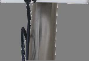
. Mast extension Tripod mast FIGURE 2-4. Pound the tapered end of the mast extension (left) into the tripod mast.")
28 2. If using mast extension(s), pound extension(s) into the mast by inserting the tapered end of the extension into the top of the mast and striking the extension top with a wooden block or hard rubber mallet (Figure 2-4). Mast extension Tripod mast FIGURE 2-4. Pound the tapered end of the mast extension (left) into the tripod mast. If using two extensions, pound the tapered end of the second extension into the top of the first extension. CAUTION Do not use a metal hammer to pound in the mast extension since this will deform the top of the mast extension. 3. If using the guy-wire kit, loosely install the guy-wire kit by following Procedure 2: Guy-wire Kit Installation (Section ). NOTE Do not tighten the turnbuckles yet. The turnbuckles will be tightened in step 5 of Procedure 3: Mounting the weather station on a Tripod or Pole (Section ). 4. Install the mast in the tripod and adjust mast height if necessary (Figure 2-5). Mast Tripod FIGURE 2-5. The mast fits in the center of the tripod. The mast height is adjusted by moving the tripod legs or removing the mast cup and sliding the mast up or down in the collars. 21

29 5. Once the mast height has been set, tighten all six collar bolts. 6. Install the tripod at the site. Refer to Procedure 1b: Ground Installations Procedure 1b: Ground Installations 1. If needed, prepare the site. A temporary site may require brush or tall weeds to be removed and footings dug if the site is not level. A permanent site may require pouring a concrete pad or fabricating some other form of a permanent base. 2. Use a rubber band to attach a level device, such as the one in the Tripod Installation Kit, to the midpoint of the tripod mast. 3. Place the tripod on the site. 4. Adjust tripod footings until the mast is level. Some adjustment is available by loosening/tightening the upper and lower collar bolts. If more adjustment is required, then for temporary sites, remove or replace soil under the feet. For permanent installations, use shims to adjust the foot foundation height. NOTE For temporary sites, ensure the soil under the tripod feet is well compacted. Otherwise the tripod may not remain level after the tripod feet have been secured to the ground. 5. Secure the tripod feet to the ground (Figure 2-6). FIGURE 2-6. For temporary sites, drive the stakes of the Tripod Stake Kit (left) through the center hole in each tripod foot (right). The stakes should be driven in until they barely contact the foot surface. For permanent sites, install user-supplied bolts through the holes in each tripod foot. 6. Follow Procedure 3: Mounting the weather station on a Tripod or Pole (Section ). 22
 from the top of the mast then loosely tighten the bracket bolts that lock it to the mast. 4.")
30 Procedure 2: Guy-Wire Kit Installation Clamps Guy-Wire Turnbuckles Bracket S-Hooks 1. Cut the guy-wire cable into three equal length pieces. 2. Loop one end of each guy-wire through a Bracket eye-bolt and clamp the guy-wire using one of the Clamps provided. 3. Install the Bracket on the tripod mast about six inches (15 cm) from the top of the mast then loosely tighten the bracket bolts that lock it to the mast. 4. Insert the mast into the Tripod and rotate the mast assembly until the bracket eye-bolts all line-up with a tripod leg then loosely tighten the mast collar bolts on the tripod. 5. Tighten the guy-wire Bracket bolts until they deform the mast by dimpling the surface to assure the Bracket does not slide when the turnbuckles are tightened. 6. Unscrew the turnbuckle until approximately 80% of both eye bolt threads extend beyond the turnbuckle body. 7. Hook an S-hook to an eyelet on each of the tripod feet. Alternatively, the S-hooks can be connected to user-supplied eye-bolts set into a concrete pad or another fixed structure. 8. One at a time, grasp a guy-wire and loop it around its corresponding S- hook to roughly determine its correct length then cut the guy-wires to eliminate any excess length. 9. Hook the unattached end of each S-hook to an eyebolt on the end of a turnbuckle. 10. Loop the free end of each guy-wire through its respective turnbuckle eyebolt and pull it tightly then clamp the guy-wire using one of the Clamps provided. 23
31 NOTE a. The guy-wires need to remain loose until after the weather station assembly has been properly oriented. The turn-buckles are tightened in step 5 of Procedure 3: Mounting the weather station on a Tripod or Pole (Section ). b. Guy-wires will stretch for a few weeks after installation. You should periodically check them for tension and re-tighten the turnbuckles as required until they stop stretching Procedure 3: Mounting the TurfWeather Station on a Tripod or Pole NOTE This procedure assumes the weather station has been setup and tested at the computer location (see Quick Start Guide), and that a tripod or pole has been installed at the site. 1. Place your weather station assembly on top of the mast or pole with the base firmly seated on the top edge of the mast or pole (Figure 2-7). TurfWeather Base 1" to 1.9" Mast or Pole FIGURE 2-7. The TurfWeather weather station assembly properly seated on a mast or pole 24

. N N FIGURE 2-9. Accurate wind direction measurements require the reference line on the wind direction sensor (right) to be aligned with Magnetic North. 4.")
32 2. Loosely tighten the U-bolt nuts so that the weather station is stable but can be rotated on the mast or pole (Figure 2-8). U-Bolt FIGURE 2-8. Two views of the TurfWeather station. The U-bolt and nuts are shown. Nuts 3. As a reference, use a magnetic compass (supplied in the optional Tripod Installation Kit) and rotate the weather station assembly until the reference line on the wind direction sensor is aligned with Magnetic North (Figure 2-9). N N FIGURE 2-9. Accurate wind direction measurements require the reference line on the wind direction sensor (right) to be aligned with Magnetic North. 4. Firmly tighten the U-bolt nuts. 5. If the Guy-wire Kit has been installed, assure that its orientation will not interfere with the solar panel (if one is installed) then evenly tighten the turnbuckles to tension the guy-wires. 6. Confirm the weather station is level by viewing the bubble level on top of the weather station (Figure 2-10). Minor adjustments can be made by tightening or loosening the appropriate guy-wire turnbuckle, placing shims between the weather station base and the top of the mast or pole, or loosening the mast bolts at the top and bottom of the tripod and shifting the vertical orientation. 25
.")
33 Bubble level FIGURE The bubble level (in red box) confirms the station is level, which is required for accurate rainfall and solar radiation measurements. 7. Connect the power source that will recharge the internal sealed rechargeable battery. If using a solar panel, follow Procedure 4: Solar Panel Installation (Section ). If using an external power supply, you need to assure it was purchased with the weather station or, if not, that it has an output of 18 VDC and that all connections are weatherproof. CAUTION a. The internal sealed rechargeable battery must be recharged to assure continued system function. b. Connecting an incompatible power source to your weather station negates your Warranty. Therefore it is recommended you check with your local distributor before connecting a power source not purchased with the station. c AC Converter when used must be installed in a non-condensing environment or a weatherproof enclosure. 26


34 8. Remove the red or green cap from the solar radiation sensor (Figure 2-11) FIGURE The red or green cap protects the solar radiation sensor while the weather station is being shipped and installed. Accurate measurements require the cap to be removed 9. Properly ground the weather station. If using the Ground Kit, refer to Procedure 5: Ground Kit Installation (Section ). 10. Turn the weather station key to the on position and return to the computer site to confirm the weather station is working properly. CAUTION a. The Ground Kit is for ground located installations only. b. Because proper grounding of the system is required for both personal safety and reliable system function, we recommend a qualified electrician install the grounding system Procedure 4: SP5 Solar Panel Installation 5 W Solar Panel 1. Place the solar panel on the mast below the station not to exceed the maximum distance allowed by the solar panel cable. 27
 to properly align the solar panel.")
35 2. Loosely tighten the U-bolt so that the solar panel is stable but can be rotated on the mast or pole. 3. Use a compass (supplied in the optional Tripod Installation Kit) to properly align the solar panel. If your installation site is in northern hemisphere locations such as the United States and China, the glass surface of the panel should face south. If your installation site is in southern hemisphere locations such as Brazil and Australia, the glass surface of the panel should face north. 4. Connect the solar panel cable to the connector on the bottom of the weather station marked Solar/DC Charger Procedure 5: Ground Kit Installation CAUTION a. Because proper earth grounding of the system is required for both personal safety and reliable system function, we recommend a qualified electrician install the grounding kit. b. If the station is not properly grounded and isolated from the Host computer, the Host computer can also be damaged by environmentally induced electrical surges. c. This kit is for ground installations only. 14 AWG copper wire Tripod clamp Ground rod clamp #4 stranded copper cable Gro 1. Connect the lug of the 14 AWG copper wire to the connector labeled Ground Lug on the bottom of the weather station (Figure 2-12). Lug FIGURE The ground lug connected to the bottom of the weather station. 28
 above the ground. 4.")
. FIGURE 2-14. The #4 cable connected to the ground rod. 29")
36 1 2 FIGURE The right close up is the 14 AWG wire and the #4 cable attached to the tripod coupling. 2. Mount the tripod coupling on the tripod mast so that it clamps the 14 AWG wire against the tripod (1 of Figure 2-13). 3. Drive the ground rod into the soil using a fence post driver or sledge hammer leaving about 3 inches (7.5 cm) above the ground. 4. Loosen the middle screw in the tripod coupling. 5. Place one end of the #4 cable in the tripod coupling hole then tighten the screw (2 of Figure 2-13). 6. Attach the other end of the #4 cable to the ground rod using the ground rod coupling (Figure 2-14). FIGURE The #4 cable connected to the ground rod. 29

37 Procedure 6: Base Radio and standard antenna installation Picture of ½ whip antenna installed on w/s here 1. Install the ½ whip antenna onto the bottom of the weather station. This will thread onto the connector marked antenna. 2. Attach to RPSMA connector on the window mount antenna to the RF401 or RF416 base radio. Remove the strip covering the adhesive on the antenna and stick it vertically to a window. 3. Attach the serial cable from the calling computer s serial port to the port marked RS232 on the RF401 or RF416 base radio. 4. Plug the wall adapter into a wall outlet and plug the barrel connector into the RF 401 or RF416 base radio connector marked DC Pwr. You should see the lights on the radio come on. FIGURE The Base RF401 and RF416 installation 30


38 Procedure 7: Short-Haul Modem installation 1. Attach the enclosure from kit onto the tripod or mounting pipe under the TurfWeather weather station using the U-Bolts supplied. Mount this underneath or opposite of the solar panel if used to prevent shadowing on the solar panel. See Figure Connect cable to the connector on the bottom of the enclosure marked Weather Station. Connect the other end of this cable to the bottom of the weather station marked RS232 and thread the thumb screws into the connector to secure cable connector to weather station. See Figures 2-17 and Connect the cable to the connector on the bottom of the enclosure marked Computer. The other end of this cable has four wires that are labelled as follows: Red +RCV, Black -RCV, Green +XMT, White -XMT. Connect these wires to the customer supplied cable using the direct burial splice kits. The wire used from the user supplied cable to connect to the Red +RCV wire should be connected to the terminal marked +RCV on the short haul modem used on the computer end of cable run. The remaining wires should follow the same procedure so that each wire is connected to the corresponding terminal on the short haul modem. Black to -RCV, etc. 4. On the computer end of the user supplied cable connect the wires as described above to the SRM-5A short haul modem. The connector marked +RCV should be connected to the wire in the user supplied cable that connects to the Red wire on the cable and so on. 5. Connect the to 25 pin adapter to the SRM-5A short haul modem. 6. Connect the serial cable to the adapter 7. Connect the other end of the serial cable to the computer. 31

.")
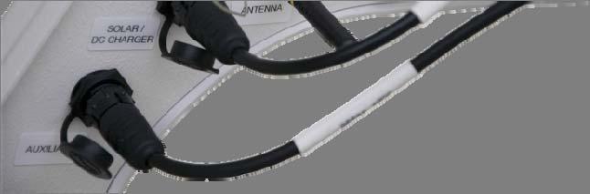
39 CAUTION a. 18 AWG is recommended for the user supplied cable, and must have at least 4 conductors plus shielding with a bare wire. This bare wire and any unused conductors should be connected to an earth ground on one end or the other to help prevent electrical noise from interfering with communication. Cable lengths exceeding ½ mile are not recommended due to additional splices, and increased probability of cable becoming damaged. Maximum of 2 miles. b. The DCE/DTE switches on the SRM-5A short haul modems are set to DCE for the computer, and DTE at the weather station (Inside enclosure) baud rate should be used with weather software and PC200W settings. FIGURE The Short Haul Enclosure Mounted 32


40 FIGURE The Cables Connected to Enclosure FIGURE The Cables Connected to Weather Station 33
41 3. Maintenance Proper maintenance of the TurfWeather weather station is essential to obtain accurate data. Equipment must be in good operating condition, which requires a program of regular inspection and maintenance. Routine and simple maintenance can be accomplished by the person in charge of the weather station. Inspect the weather station weekly when first installed to get an understanding of how often cleaning and inspecting should be performed. Keep the weather station level for accurate solar radiation and rain measurements. Use the level bubble located on top of weather station for reference. More difficult maintenance such as sensor replacement can be accomplished with instructions included in this manual, or weather station can be sent to Campbell Scientific if preferred. 3.1 Solar Panel P/N SP5 3.2 Battery Pack P/N An occasional cleaning of the glass on the solar panel will improve its efficiency. Use warm mildly soapy water and a clean cloth. Rinse with clean water. The Battery pack is a 12 Volt, 0.8 AHr battery with a special connector. It has a life expectancy of 3 to 5 years. It is located inside the weather station. It is a sealed lead acid battery design, and if it is discharged below 11.0 volts it may become damaged and no longer accept a charge regardless of the age of the battery. PC200W and most weather software will display the weather station battery voltage. Typical measurements should be between 12.5 and 13.5 volts. See Section 3.11 Battery Pack Removal and Replacement Procedure for instructions on replacement. 3.3 Temperature/Relative Humidity sensor P/N The Temperature/Relative Humidity sensor has a life expectancy of 18 months. The Relative Humidity measurement will begin to drop off as the sensor ages. It is located on the bottom of the weather station inside the slotted cylinder shaped protector. Take care not to expose this sensor to overspray from pesticides, fertilizers, etc. Use a soft brush to remove dust and cob webs from sensor area. See Section 3.12 Temperature/Relative Humidity Sensor Assembly Removal and Replacement Procedure for instructions on replacement. 3.4 Solar Radiation sensor P/N The Solar Radiation sensor has a life expectancy of approximately 5 years.at an expected 2% per year degradation rate. This sensor is replaced rather than recalibrated. It is the small round sensor located on the opposite end from the wind sensors. Keep this sensor clean using a soft cloth and very mild soapy water, and follow up with a clean damp cloth with water only. See Section 3.13 Solar Radiation Sensor Removal and Replacement Procedure for instructions on replacement. 34
42 3.5 Rain Gauge P/N The Rain Gauge has a life expectancy of 5 years or more. It is the box shaped sensor on top of the weather station. Keep the funnel area clean from leafs, pine needles etc. Keep the tipping mechanism spoon clean by removing accumulated dirt build up. The spoon can be accessed by removing the top funnel from the main body of the Rain Gauge. Hold the body with one hand while removing the funnel. The body, base, and funnel all just press together with no fasteners holding them. 1 tip of the spoon will result in 1 mm being measured. 1 mm is equal to inch. See Section 3.14 Rain Gauge Removal and Replacement Procedure for instructions on replacement. 3.6 Wind Speed Sensor P/N The Wind Speed sensor has a life expectancy of 5 years or more. It is the black sensor with three cups that rotate as the wind blows. To check the wear of this sensor gently rotate the sensor using your thumb and forefinger on the top point of the sensor. The sensor should move freely and feel very smooth. See Section 3.15 Wind Speed Sensor Removal and Replacement Procedure for instructions on replacement. 3.7 Wind Direction Sensor P/N Memory Battery P/N The Wind Direction sensor has a life expectancy of 5 years or more. It is the black sensor with a tail on one end and a stainless steel nose on the other end. To check the sensor for wear gently rotate the sensors top half. The sensor should move freely and feel very smooth. See Section 3.16 Wind Direction Sensor Removal and Replacement Procedure for instructions on replacement. The Memory Battery is a small coin cell type battery that will keep the clock time correct and the stored data when the power supply and battery pack are not supplying power to station. Life expectancy is 5 years or more. This battery voltage should be above 3 volts, and can be displayed using PC200W software. The battery manufacturer's model number is the CR1016. See Section 3.17 Memory Battery Removal and Replacement Procedure for instructions on replacement. 3.9 Auxiliary Battery Unit Installation Procedure The installation of a TurfWeather weather station Auxiliary Battery Unit does not require training, special tools, or test equipment. However, the main body of the weather station does need to be opened, and the person performing this procedure should observe basic electro-static discharge (ESD) precautions (described below) to avoid damage to the weather station electronics inside the main body of the weather station. There is no personal electrical hazard involved, and this procedure can be accomplished by anyone possessing basic mechanical skills. Please read this entire procedure before beginning work. Tools Required: ½ inch wrench 5/16 inch wrench #2 Phillips screwdriver Small wire cutter 35


43 P/N Auxiliary Battery Unit kit components: Enclosure with 7AHr battery Battery Cable U-bolt, washers and brass nuts 1. Preparation: a. Turn the power switch on the weather station to the OFF position. b. Disconnect the power input cable and ground wire connections from the weather station, using the 5/16 inch wrench for the ground wire connection. c. Remove the weather station from its location by using the ½ inch wrench to loosen the two U-bolt nuts securing the weather station to its mast. Make note of the orientation of weather station. NOTE: Do not remove the mast bracket from the weather station. d. Bring the weather station to an enclosed location, preferably near the Host computer, and place it on a flat stable surface with an area of at least three times the size of the weather station base. 2. Battery Pack Removal: a. Invert the weather station main body and rest it on a support that eliminates any stress on the wind speed or wind direction sensors, and/or the rain gauge. A rolled bath towel placed in the center of the main body, next to the rain gauge will generally suit the purpose. 36
44 b. Remove the seven Phillips head screws on the base of the main body that hold the base section to the electronics enclosure section. Do not remove the Phillips head screws that connect the mast bracket to the weather station base. Notice that the three screws along the end with the wind sensors are shorter than the remaining four screws. c. Gently separate the electronics enclosure and base sections of the weather station main body, taking care not to place any stress on the wires that connect the two sections. d. Rest the base section next to the electronics section and locate the battery pack within the electronics section. It is a gray and black rectangular component at the front of the electronics section. It is retained by a white metal bracket that is held in place with two Phillips head screws. There is a cable, consisting of a red and a black wire, or a white and black wire that connects the battery pack to the main electronics board. e. Locate the other end of the battery pack cable on the main electronics board. It terminates in a white connector plugged into the main electronics board marked Battery. The wires are restrained along their length with either plastic cable ties, or with reusable cable restraints. Determine which type your weather station has and then release the wires by either cutting the cable ties with the small wire cutter, or by releasing the cable restraints. NOTE: Do not cut the wires to remove the battery pack. 37

45 f. Disconnect the white battery pack cable connector from the main electronics board. NOTE: Maintain ESD isolation by not touching any electronics boards or components on the boards inside the weather station. g. Use the Phillips screwdriver to remove the two screws holding the battery pack bracket into the electronics section, and remove the bracket. h. Lift the battery pack from the weather station. NOTE: The weather station uses a maintenance free lead-acid battery and must be properly disposed of. Do not dispose of this battery pack in a municipal landfill, or by burning it. If you do not know where to dispose of a battery pack, then contact your local solid waste disposal site for instructions. Reinstall bracket and screws without battery. 3. Wiring modifications: a. Locate the yellow wire marked Batt + and remove protective tape from the end. b. Locate the terminal marked Battery + on the circuit board and open the connector lever. Install the yellow wire marked Batt + into this connector and close the lever. 38

46 c. Use new cable ties to capture the cable as it was before you clipped the original cable tie(s), or reuse the original ties if possible. d. Place the two sections of the weather station main body together, making sure that none of the wiring bundles will be crushed by the edges, or by the seven housing screws when the sections are secured. e. Reinstall and tighten the seven screws that hold the weather station main body sections together. f. Reinstall TurfWeather weather station in original location and orientation. Reconnect Solar/Charger cable as before. 4. Enclosure Installation: a. Locate the enclosure underneath or opposite of the solar panel to prevent shadowing on the solar panel. b. Attach the enclosure to TurfWeather weather station mounting pole using the U-bolt, flat washers, locking washers, and brass nuts supplied. Using the ½ inch wrench tighten the two U-bolt nuts. c. Attach the cable s 2 pin connector end to the bottom of the enclosure. d. Attach the cable s 6 pin connector to the bottom of the TurfWeather weather station s Auxiliary connector. 39


47 40
48 3.10 High Gain Base Station Antenna Installation Procedure The physical installation of a TurfWeather weather station high gain base station antenna system does not require training or special tools. However, assurance that the antenna system is properly grounded should be confirmed by a qualified RF systems technician or engineer. Failure to properly ground the antenna system will invalidate the Warranty of the antenna and any attached equipment, and it will expose equipment attached to the antenna to a high risk of damage from environmental electrostatic discharge, including lightning. WARNING Under no circumstances should installation be accomplished during inclement weather to avoid personal hazard due to lightning. Please read this entire procedure before beginning work. Tools required: ½ inch wrench 3/8 inch wrench #2 Phillips screwdriver Customer supplied materials required: Antenna mounting pole 1 ¼ - 2 inch O.D. metal pipe, or tripod assembly Pole/tripod mounting hardware Spade or ring lug connector (00 gage) Antenna kit components required: High gain Yagi-directional antenna (900MHz, P/N or 2.4GHz, P/N 22072) Antenna mounting bracket NTN-L50 or -L100 low loss antenna cable Polyphaser impulse suppressor module (900MHz, IS-50NX-C2 p/n 14462; or 2.4GHz, LCU2.4 p/n 16982) COAX RPSMA Polyphaser-to-RF401 cable (included with p/n and p/n 16982) Weather station grounding kit P/N Weather station grounding kit components: Copper clad grounding rod Heavy gage (00) ground cable Ground rod-to-cable clamp brass Mast ground clamp (discard - not required for antenna installation) Weather station ground wire green (discard not required for antenna installation) NOTE The P/N Grounding kit contains basic components used for grounding either a tripod, or a buss bar. This kit may need to be supplemented by the user to meet the requirements of any specific site. 41
49 1. Location Preparation: a. Determine the best location for the antenna, assuming that the distance from the antenna to the RF401 base station is equal to, or less than, the length of the NTN-Lxx antenna cable. b. Assure that the ground rod is installed into the soil as close to the location of the Polyphaser as is possible. NOTE: A ground wire (00 gage) is supplied but it may not be long enough for all installations. If a longer ground cable is required, purchase a continuous length to meet the site requirement but always use the minimum length necessary. Do not reduce the gage of this wire if a longer length is required. An alternate method of earth grounding may be employed but should be confirmed by a qualified RF technician before use. c. Mount the Polyphaser within 5 feet of the location of the RF401 base station on a ground plane, or ground buss bar, inside a weatherproof enclosure or building. Mounting recommendations are supplied with the Polyphaser. NOTE: The ground plane or buss bar will also be the connection point for the earth ground cable to the exterior ground rod, or interior earth ground connection. d. Connect the heavy gage (00 gage) ground wire to the ground plane or buss bar using a 00 bolted ring or spade lug connector (not supplied). Connect the other end of the heavy gage ground wire to the ground rod using the brass rod clamp supplied, or connect to the alternate interior earth ground point. e. Verify connection to the earth ground from the case of the Polyphaser. 2. Component Installation: a. Mount the antenna in the proper orientation, with the connector at the bottom. b. Connect one end of the antenna cable to the antenna and install the cable up to the location of the Polyphaser. Assure that a drip loop is maintained in the cable at the base of the antenna, and at the point where the cable will enter a weatherproof enclosure or building. The drip loops will minimize the amount of rainwater that will run down the cable to the enclosure or building. NOTE: The minimum bend radius of the antenna cable is 6 inches. Tight bends in the antenna cable, or clamps that crush the cable, will damage the internal insulation and compromise the cable. Handle the antenna cable with care. c. Connect the antenna cable to the Polyphaser module connector marked ANTENNA. d. Connect one end of the short COAX RPSMA Polyphaser-to-RF401 cable to the EQUIPMENT side of the Polyphaser module, and the other end to the antenna connector on the RF
50 3. Principle of Operation: a. A Yagi high gain antenna is a directional RF device designed to minimize signal attenuation at the base station location, thereby providing the maximum available energy at the antenna for communication with the remotely located equipment (i.e.: the weather station). This antenna does need to be aimed and the best result is obtained with a clear line of sight to the remote transceiver. If you can see the weather station, the system has a clear line of sight. b. The Polyphaser senses the presence of a high voltage electrostatic energy pulse and passes it to earth ground before it can damage the RF System Test: a. Initiate the system software and verify that the RF401 will communicate with the weather station. See TurfWeather Quick Start Guide NOTE IMPROPER GROUNDING OF THE SYSTEM WILL COMPROMISE ALL PROTECTIVE COMPONENTS AND RESULT IN SYSTEM DAMAGE IN THE EVENT OF AN ELECTROSTATIC DISCHARGE EVENT. THE GROUND SYSTEM SHOULD BE REVALIDATED ON AN ANNUAL BASIS TO ASSURE THAT CORROSION AT CONNECTORS HAS NOT COMPROMISED THE GROUND SYSTEM Battery Pack (P/N 14159) Removal and Replacement Procedure The removal and replacement of a TurfWeather weather station battery pack does not require training, special tools, or test equipment. However, the main body of the weather station does need to be opened, and the person replacing this battery should observe basic electro-static discharge (ESD) precautions (described below) to avoid damage to the weather station electronics inside the main body of the weather station. There is no personal electrical hazard involved, and this procedure can be accomplished by anyone possessing basic mechanical skills. Please read this entire procedure before beginning work. Tools Required: ½ inch wrench 5/16 inch wrench #2 Phillips screwdriver Small wire cutter 1. Preparation: a. Turn the power switch on the weather station to the OFF position. b. Disconnect the power input cable and ground wire connections from the weather station, using the 5/16 inch wrench for the ground wire connection. 43
51 c. Remove the weather station from its location by using the ½ inch wrench to loosen the two U-bolt nuts securing the weather station to its mast. Make note of the orientation of weather station. NOTE: Do not remove the mast bracket from the weather station. d. Bring the weather station to an enclosed location, preferably near the Host computer, and place it on a flat stable surface with an area of at least three times the size of the weather station base. 2. Battery Pack Removal: a. Invert the weather station main body and rest it on a support that eliminates any stress on the wind speed or wind direction sensors, and/or the rain gauge. A rolled bath towel placed in the center of the main body, next to the rain gauge will generally suit the purpose. b. Remove the seven Phillips head screws on the base of the main body that hold the base section to the electronics enclosure section. Do not remove the Phillips head screws that connect the mast bracket to the weather station base. Notice that the three screws along the end with the wind sensors are shorter than the remaining four screws. c. Gently separate the electronics enclosure and base sections of the weather station main body, taking care not to place any stress on the wires that connect the two sections. d. Rest the base section next to the electronics section and locate the battery pack within the electronics section. It is a gray and black rectangular component at the front of the electronics section. It is retained by a white metal bracket that is held in place with two Phillips head screws. There is a cable, consisting of a red and a black wire, or a white and black wire that connects the battery pack to the main electronics board. 44
52 e. Locate the other end of the battery pack cable on the main electronics board. It terminates in a white connector plugged into the main electronics board marked Battery. The wires are restrained along their length with either plastic cable ties, or with reusable cable restraints. Determine which type your weather station has and then release the wires by either cutting the cable ties with the small wire cutter, or by releasing the cable restraints. NOTE: Do not cut the wires to remove the battery pack. f. Disconnect the white battery pack cable connector from the main electronics board. NOTE: Maintain ESD isolation by not touching any electronics boards or components on the boards inside the weather station. g. Use the Phillips screwdriver to remove the two screws holding the battery pack bracket into the electronics section, and remove the bracket. h. Lift the battery pack from the weather station. NOTE: The weather station uses a maintenance free lead-acid battery and must be properly disposed of. Do not dispose of this battery pack in a municipal landfill, or by burning it. If you do not know where to dispose of a battery pack, then contact your local solid waste disposal site for instructions. 3. Battery Pack Replacement: a. Insert the new battery pack into the weather station where the previous battery pack was located. b. Replace the battery pack retainer and tighten the Phillips head screws that hold it into the electronics section. Take care not to crimp the cable from the battery pack under the battery pack, or the retainer. 45

53 c. Carefully connect the white cable connector to the main electronics board, taking care not to touch the board or any components on electronics boards inside the weather station. d. Align the battery pack cable in the cable restraints and again clamp them around the entire cable bundle. If your weather station uses cable ties, then use the ties supplied with the new battery pack and capture the cable as it was before you clipped the original cable tie(s). e. Place the two sections of the weather station main body together, making sure that none of the wiring bundles will be crushed by the edges, or by the seven housing screws when the sections are secured. f. Reinstall and tighten the seven screws that hold the weather station main body sections together. 4. System Test: a. Turn on the weather station power switch. b. Look into the small window on the bottom of the weather station marked Scan Receive and confirm that the LED flashes every ten seconds. c. Re-install the weather station on its mast, and reconnect the ground and power wires Temperature/Relative Humidity Sensor Assembly (P/N 14144) Removal and Replacement Procedure Please read this entire procedure before beginning work. The removal and replacement of a TurfWeather weather station temperature/relative humidity (Temp/RH) sensor assembly does not require training, special tools, or test equipment. However, the main body of the weather station does need to be opened, and the person replacing this sensor 46
54 should observe basic electro-static discharge (ESD) precautions (described below) to avoid damage to the weather station electronics inside the main body of the weather station. There is no personal electrical hazard involved, and this procedure can be accomplished by anyone possessing basic mechanical skills. Tools Required: ½ inch wrench 5/16 inch wrench small wire cutter #2 Phillips screwdriver Time Required: minutes 1. Preparation: a. Turn the power switch on the weather station to the OFF position. b. Disconnect your solar panel or your DC power supply input cable from the weather station. c. Disconnect the ground wire connections from the weather station, using the 5/16 inch wrench. d. Remove the weather station from its location by using the ½ inch wrench to loosen the two U-bolt nuts that secure the weather station to its mast. NOTE: Do not remove the mast bracket from the weather station. e. Bring the weather station to an enclosed location, preferably near the Host computer, and place it on a flat stable surface with an area of at least three times the size of the weather station base. 2. Sensor Removal: a. Invert the weather station main body and rest it on a support that eliminates any stress on the wind speed or wind direction sensors, and/or the rain gauge. A rolled bath towel placed in the center of the main body, next to the rain gauge will generally suit the purpose. b. Remove the two Phillips head screws on the base of the main body that hold the mounting cover over the tube that covers the temperature/relative humidity sensor. c. Gently separate these components and pull out the temp/rh sensor until the connector is exposed. 3. Sensor Replacement: a. Do not contaminate either of the sensor elements by exposing them to solvents. b. Unplug the old sensor, and plug in the new sensor. 47
 and turn on the weather station power switch.")
55 4. Reassemble the mounting cover and tube assemble with the new sensor onto the main body. 5. System Test: a. Connect the weather station to the Host computer using the short RS- 232 test cable (if a wired system) and turn on the weather station power switch. Initiate communications with the weather station using PC200W or T.Weather. b. Verify that the temperature and relative humidity sensors are reporting values. Gently blow air into the sensor protective screen on the bottom of the weather station and verify that both the temperature and relative humidity values increase. Stop blowing air on the sensors, and after a brief period the values should slowly decrease until the sensors return to equilibrium with the surrounding environment. c. Re-install the weather station on its mast, and then reconnect power and earth ground cables Solar Radiation Sensor (P/N 14009) Removal and Replacement Procedure The removal and replacement of a TurfWeather weather station solar radiation sensor does not require training, special tools, or test equipment. However, the main body of the weather station does need to be opened, and the person replacing this sensor should observe basic electro-static discharge (ESD) precautions (described below) to avoid damage to the weather station electronics inside the main body of the weather station. There is no personal electrical hazard involved, and this procedure can be accomplished by anyone possessing basic mechanical skills. Please read this entire procedure before beginning work. 48
56 Tools Required: ½ inch wrench 5/16 inch wrench #2 Phillips screwdriver 1. Preparation: a. Turn the power switch on the weather station to the OFF position. b. Disconnect the power input cable and ground wire connections from the weather station, using the 5/16 inch wrench for the ground wire connection. c. Remove the weather station from its location by using the ½ inch wrench to loosen the two U-bolt nuts that secure the weather station to its mast. NOTE: Do not remove the mast bracket from the weather station. d. Bring the weather station to an enclosed location, preferably near the Host computer, and place it on a flat stable surface with an area of at least three times the size of the weather station base. 2. Solar Radiation Sensor Removal: a. Locate the solar radiation sensor on the front of the weather station. It is the gray plastic knob shaped protrusion on the top, front of the weather station. It is stamped on its side with the words CSI APOGEE PYRC(number). b. Locate the Phillips head screw on the side of the sensor. Remove the screw but do not pull on, or attempt to remove the sensor at this time. c. Invert the weather station main body and rest it on a support that eliminates any stress on the wind speed or wind direction sensors, and/or the rain gauge. A rolled bath towel placed in the center of the main body, next to the rain gauge will generally suit the purpose. d. Remove the seven Phillips head screws on the base of the main body that hold the base section to the electronics enclosure section. Do not remove the Phillips head screws that connect the mast bracket to the weather station base. Notice that the three screw along the end with the wind sensors are shorter than the remaining four screws. e. Gently separate the electronics enclosure and base sections of the weather station main body, taking care not to place any stress on the wires that connect the two sections. f. Rest the base section next to the electronics section and locate the battery pack within the electronics section. It is a gray and black rectangular component at the front of the electronics section. It is retained by a white metal bracket that is held in place with two Phillips head screws. 49
57 g. Use the Phillips screwdriver to remove the two screws holding the battery pack bracket into the electronics section, and remove the bracket. h. Lift the battery pack from the electronics section and rest it next to the weather station. i. Locate the two wires that come from solar radiation sensor and follow them to their end connector on the weather station main electronics board. Cut, or disconnect any cable retaining ties along the length of the wires. j. Locate the screws on the corners of the main electronics board (largest green electronics board) and touch one finger to one of the screws on a corner of the board, then carefully disconnect the black solar radiation cable connector. NOTE: Touching a screw will ground any electro-static energy difference between you and the main electronics board. Do not be concerned, as this will not shock you or create a spark. k. Remove the solar radiation sensor by gently pulling it off its mounting post as you feed the wires through the hole in the top of the weather station module. 3. Solar Radiation Sensor Replacement: a. Insert the wire cable from the new solar radiation sensor into the weather station electronics module through the mounting post hole where the previous solar radiation sensor was located. b. Again touch a finger to a screw on a corner of the main electronics board and then carefully reconnect the black solar radiation sensor connector. NOTE: Touching the screw will ground any electro-static energy difference between you and the weather station main electronics board. Do not be concerned, as this will not shock you or create a spark. c. Align the solar radiation sensor cable in the cable restraints and again clamp them around the cable bundle. If your weather station uses cable ties, then use the ties supplied with the new solar radiation sensor and capture the cable as it was before you clipped the original cable tie(s). d. Replace the battery pack in its original location. e. Replace the battery pack retainer and tighten the Phillips head screws that hold it into the electronics section. Take care not to crimp the cable from the battery pack or the solar radiation sensor under the battery pack, or the retainer. f. Place the two sections of the weather station main body together, making sure that none of the wiring bundles will be crushed by the edges or by the seven housing screws when the two sections are secured with screws. 50


58 g. Reinstall and tighten the seven screws that hold the weather station main body sections together. h. Press the solar radiation sensor down onto its mounting post until it is firmly seated, then tighten the Phillips head screw on the side until you cannot pull the sensor off of the post. Take care not to overtighten the screw as over-tightening could crack the sensor post. 4. System Test: a. Connect the weather station to the Host computer using the short RS- 232 test cable (if a wired system) and turn on the weather station power switch. Initiate communications using PC200W or T.Weather. b. Point a strong flashlight directly at the top of the solar radiation sensor and verify that the solar radiation sensor is reporting a value. NOTE: When the weather station is reinstalled at its permanent location the solar radiation sensor should report a value near to 1000 W m -2, on a clear day, with a bright sun directly overhead. c. Re-install the weather station on its mast, and reconnect the ground and power wires Rain Gauge (P/N 25585) Removal and Replacement Procedure Introduction: The removal and replacement of a TurfWeather weather station rain gauge does not require training, special tools, or test equipment. The main body of the weather station does not need to be opened, there is no electrical hazard involved, and this procedure can be accomplished by anyone possessing basic mechanical skills. Please read this entire procedure before beginning work. 51
59 Tools Required: ½ inch wrench 5/16 inch wrench Small needle nosed pliers 1. Preparation: a. Turn the power switch on the weather station to the OFF position. b. Disconnect the power input cable and ground wire connections from the weather station, using the 5/16 inch wrench for the ground wire connection. c. Remove the weather station from its location by using the ½ inch wrench to loosen the two U-bolt nuts that secure the weather station to its mast. NOTE: Do not remove the mast bracket from the weather station. d. Bring the weather station to an enclosed location, preferably near the Host computer, and place it on a flat stable surface. 2. Sensor Removal: a. Identify the rain gauge as the white rectangular box located in the center, on top of the weather station. b. Grasp the main body of the rain gauge and gently pull it off of the weather station. This will expose two wires, leaving the rain gauge base attached to the weather station. c. Remove the wires from their connections inside the rain gauge. The wires are screwed to a terminal strip, then loosen the screws and remove the wires. 3. Sensor Replacement: a. Connect the wires to the replacement rain gauge. Tighten the terminal screws. It does not matter which wire is attached to which pin, this connection is not polarity sensitive. b. You will notice that the rain gauge wires pass through a small indented location on one side of the rain gauge base. When you replace the rain gauge back onto its base you must make sure that the wires are within the indent to assure they will not be crushed or crimped by the rain gauge. c. Locate the rain gauge on its base and gently press it down until it is firmly seated. 52
 and turn on the weather station power switch; or initiate communications if your weather")
60 4. System Test: a. Connect the weather station to the Host computer using the short RS- 232 test cable (if a wired system) and turn on the weather station power switch; or initiate communications if your weather station is wireless. b. Gently remove the top portion (catch basin) of the rain gauge and identify the black spoon shaped tipping bucket inside the rain gauge. c. Using your index finger, gently press the spoon down until you hear a faint click sound. This is the tip counting switch responding to the tiny magnet on the side of the spoon shaped tipping bucket. Repeat this action several times and look for a change in the rain values reported by the PC200W or T.Weather. Each click is equal to 0.04 inches (1 mm) of rain. NOTE: Every rain gauge is factory calibrated before it is shipped. If you want to validate calibration please refer to the calibration instructions for the rain gauge and complete the calibration before you reinstall the weather station on its mast. d. Replace the catch basin on the rain gauge and re-install the weather station on its mast Wind Speed Sensor (Anemometer) (P/N 14010) Removal and Replacement Procedure The removal and replacement of a TurfWeather weather station wind speed sensor does not require training, special tools, or test equipment. The main body of the weather station does not need to be opened, there is no electrical hazard involved, and this procedure can be accomplished by anyone possessing basic mechanical skills. Please read this entire procedure before beginning work. 53
61 Tools Required: ½ inch wrench 5/16 inch wrench ¼ inch wrench #2 Phillips screwdriver. 1. Preparation: a. Turn the power switch on the weather station to the OFF position. b. Disconnect the power input cable and ground wire connections from the weather station, using the 5/16 inch wrench for the ground wire connection. c. Remove the weather station from its location by using the ½ inch wrench to loosen the two U-bolt nuts that secure the weather station to its mast. NOTE: Do not remove the mast bracket from the weather station. d. Bring the weather station to an enclosed location, preferably near the Host computer, and place it on a flat stable surface. 2. Sensor Removal: a. Identify the wind speed sensor as the sensor with three cups that rotate around the main sensor body. It is located on the top, rear of the weather station main body. NOTE: Do not twist or place side pressure on either the wind speed or wind direction sensors at any time during this sensor removal/replacement process as it may cause them to break off of the weather station main body. b. Just below the sensor rotating cups, there is a flexible boot that will peel down from the top. Without using tools, peel the boot down, folding it back upon itself and the sensor mounting post. This will expose two wires connected to two separate threaded terminal studs, retained by ¼ inch nuts. NOTE: Take care not to place side pressure on the sensor itself, and do not place downward pressure on the weather station main body as this may damage the Temp/RH sensor cage on the underside of the weather station. c. Using the ¼ inch wrench, loosen the nuts and remove the wires. d. Locate the single Phillips head screw on the side of the sensor body. NOTE: This is not either of the screws next to the threaded terminal studs. Using the Phillips screwdriver, remove the screw. e. Remove the sensor from its post by gently twisting and pulling it away from the post. 3. Sensor Replacement: a. Press the new wind speed sensor on the post until it is seated on the top of the mounting post. NOTE: Orientation of this sensor is not important but it must be firmly seated on its mounting post. 54


62 b. Install and tighten the Phillips head screw on the side of the sensor body one half turn beyond when it is initially tight in the hole (after it has bottomed against the sensor post). Gently pull on the sensor body to assure it is firmly attached to the sensor post. If not, then tighten the screw until the sensor cannot be removed. c. Re-attach the two wires to the correct threaded terminal studs and tighten the nuts using the ¼ inch wrench. NOTE: It does not matter which wire is connected to which terminal stud. These connections are interchangeable. d. Unroll the rubber protective boot and assure that it completely covers the lower portion of the wind speed sensor, just as it did when you started this process. 4. System Test: a. Connect the weather station to the Host computer using the RS-232 test cable (if a wired system) and turn the weather station power switch to the ON position. Initiate communications with your weather station using PC200W or T.Weather. b. Manually spin the sensor cups for a minute or two to verify that the wind speed sensor is reporting a value. c. Turn the weather station power switch to the OFF position. d. Re-install the weather station on its mast; then reconnect power and ground wires before turning the weather station power switch to the ON position. 55
63 3.16 Wind Direction Sensor (P/N 14011) Removal and Replacement Procedure The removal and replacement of a TurfWeather weather station wind direction sensor does not require training, special tools, or test equipment. The main body of the weather station does not need to be opened, there is no electrical hazard involved, and this procedure can be accomplished by anyone possessing basic mechanical skills. Please read this entire procedure before beginning work. Tools Required: ½ inch wrench 5/16 inch wrench ¼ inch wrench #2 Phillips screwdriver. 1. Preparation: a. Turn the power switch on the weather station to the OFF position. b. Disconnect the power input cable and ground wire connections from the weather station, using the 5/16 inch wrench for the ground wire connection. c. Remove the weather station from its location by using the ½ inch wrench to loosen the two U-bolt nuts that secure the weather station to its mast. NOTE: Do not remove the mast bracket from the weather station. d. Bring the weather station to an enclosed location, preferably near the Host computer, and place it on a flat stable surface. 2. Sensor Removal: a. Identify the wind direction sensor as the black vane (arrow shaped) sensor located on the top, rear of the weather station main body. NOTE: Do not twist or place side pressure on the wind direction or wind speed sensors at any time during this sensor removal/replacement process as it may cause them to break off of the weather station main body. b. Just below the sensor moveable vane, there is a flexible boot that will peel down from the top. Without using tools, peel the boot down, rolling the edge back upon itself and the sensor mounting post. Take care not to place side pressure on the sensor itself. This will expose three wires connected to three separate threaded terminal studs, held tight by ¼ inch nuts. c. Using the ¼ inch wrench, loosen the nuts and remove the wires, taking care to note which wires go on which threaded terminal studs. d. Locate the single Phillips head screw on the side of the sensor body. NOTE: This is NOT either of the screws next to the threaded terminal studs. Using the Phillips screwdriver, remove the screw. 56
64 e. Remove the sensor from its post by gently twisting and pulling it away from the post. 3. Sensor Replacement: a. Press the new wind direction sensor on the post until it is seated firmly on the top of the post. b. Gently twist the sensor body until the raised North reference is properly aligned. NOTE: Refer to the Quick Start Guide delivered with the weather station for a picture of a properly aligned wind direction sensor. c. Install and tighten the Phillips head screw on the side of the sensor one half turn beyond when it is initially tight in the hole (after the screw has bottomed against the sensor post). Gently pull on the sensor body to assure it is firmly attached to the sensor post. If not, then tighten the screw until the sensor cannot be moved. d. Re-attach the three wires to the correct threaded terminal studs and tighten the nuts using the ¼ inch wrench. NOTE: If you did not note the correct threaded terminal studs, look at the base of the sensor and count clockwise from the embossed N reference mark. The first stud will take the black wire, the second the blue wire and the third the red wire. e. Unfold the rubber protective boot and assure that it completely covers the lower portion of the wind direction sensor, just as it did before you started this process. 4. System Test: a. Connect the weather station to the Host computer using the RS-232 test cable (if a wired system) and turn on the weather station power switch. Initiate communications with your weather station using PC200W or T.Weather. b. Verify that the wind direction sensor is reporting a position. The position number should be -0- when the tail of the sensor vane is aligned with the North reference. Confirm that the wind direction number increases when the vane is rotated clockwise. c. Re-install the weather station on its mast. 57

 precautions (described below) to avoid damage to the weather station electronics inside the main body of the weather station.")


65 3.17 Memory Battery (P/N 15598) Removal and Replacement Procedure The removal and replacement of a TurfWeather weather station memory battery does not require training, special tools, or test equipment. However, the main body of the weather station does need to be opened, and the person replacing this electronics board should observe basic electro-static discharge (ESD) precautions (described below) to avoid damage to the weather station electronics inside the main body of the weather station. There is no personal electrical hazard involved, and this procedure can be accomplished by anyone possessing basic mechanical skills. Please read this entire procedure before beginning work. Tools Required: ½ inch wrench 5/16 inch wrench #2 Phillips screwdriver Wooden toothpick or non-metallic tweezers 1. Preparation: a. Turn the power switch on the weather station to the OFF position. b. Disconnect the power input cable and ground wire connections from the weather station, using the 5/16 inch wrench for the ground wire connection. c. Remove the weather station from its location by using the ½ inch wrench to loosen the two U-bolt nuts that secure the weather station to its mast. NOTE: Do not remove the mast bracket from the weather station. 58
66 d. Bring the weather station to an enclosed location, preferably near the Host computer, and place it on a flat stable surface with an area of at least three times the size of the weather station base. 2. Memory Battery Removal: a. Invert the weather station main body and rest it on a support that eliminates any stress on the wind speed or wind direction sensors, and/or the rain gauge. A rolled bath towel placed in the center of the main body, next to the rain gauge will generally suit the purpose. b. Remove the seven Phillips head screws on the base of the main body that hold the base section to the electronics enclosure section. Do not remove the Phillips head screws that connect the mast bracket to the weather station base. Notice that the three screws along the end with the wind sensors are shorter that the remaining four screws. c. Gently separate the electronics enclosure and base sections of the weather station main body, taking care not to place any stress on the wires that connect the two sections. d. Rest the base section next to the electronics section and locate the main electronics board within the electronics section. It is the largest green rectangular electronics board in the weather station electronics section. Locate the screws at the corners of the main electronics board and touch one of them with a finger to discharge any electrostatic difference between you and the electronics. NOTE: Touching the screw(s) will not shock you or create a spark. e. Locate the small disc shaped memory battery in the center of the main electronics board and, using a fingernail, gently lift the battery retaining clip; then use your wooden toothpick or non-metallic tweezers to extract the battery from the battery holder. 3. Memory Battery Replacement: a. Determine which side of the new battery is the positive side. This will have a + stamped into the surface. This is the side that must be up (visible) when the battery is installed in the battery holder. b. Lift the battery retaining clip slightly and slip the battery into the battery holder insuring that it is correctly seated and tightly held in place by the battery retaining clip. c. Place the two sections of the weather station main body together, making sure that none of the wiring bundles will be crushed by the edges or by the seven housing screws when the two sections are secured with screws. d. Reinstall and tighten the seven screws that hold the weather station main body sections together. 59
67 4. System test: a. Turn on the weather station b. Look into the small window on the bottom of the weather station marked Scan Receive and confirm that the LED flashes every ten seconds. c. Re-install the weather station on its mast, and reconnect the ground and power wires Main Electronics Board (Motherboard) Removal and Replacement Procedure The removal and replacement of a TurfWeather weather station main electronics board does not require training, special tools, or test equipment. However, it is not a user repairable item and must be returned to an authorized local Toro distributor for evaluation and repair. Additionally, the main body of the weather station does need to be opened, and the person replacing this electronics board should observe basic electro-static discharge (ESD) precautions (described below) to avoid damage to the weather station electronics inside the main body of the weather station. There is no personal electrical hazard involved, and this procedure can be accomplished by anyone possessing basic mechanical skills. Please read this entire procedure before beginning work. Tools Required: ½ inch wrench 5/16 inch wrench #2 Phillips screwdriver 60
68 1. Preparation: a. Turn the power switch on the weather station to the OFF position. b. Disconnect the power input cable and ground wire connections from the weather station, using the 5/16 inch wrench for the ground wire connection. c. Remove the weather station from its location by using the ½ inch wrench to loosen the two U-bolt nuts that secure the weather station to its mast. NOTE: Do not remove the mast bracket from the weather station. d. Bring the weather station to an enclosed location, preferably near the Host computer, and place it on a flat stable surface with an area of at least three times the size of the weather station base. 2. Main Electronics Board Removal: a. Invert the weather station main body and rest it on a support that eliminates any stress on the wind speed or wind direction sensors, and/or the rain gauge. A rolled bath towel placed in the center of the main body, next to the rain gauge will generally suit the purpose. b. Remove the seven Phillips head screws on the base of the main body that hold the base section to the electronics enclosure section. Do not remove the Phillips head screws that connect the mast bracket to the weather station base. Notice that the three screws along the end with the wind sensors are shorter than the remaining four screws. c. Gently separate the electronics enclosure and base sections of the weather station main body, taking care not to place any stress on the wires that connect the two sections. d. Rest the base section next to the electronics section and locate the main electronics board within the electronics section. It is the largest green rectangular electronics board in the weather station electronics section. e. Locate the screws at the corners of the main electronics board and touch one finger to one of the screws. NOTE: Touching the screw will ground any electro-static energy difference between you and the weather station main electronics board. Do not be concerned, as this will not shock you or create a spark. f. Remove the four Phillips head screws that attach the main electronics board to the weather station electronics section. g. Note the gray plastic connector on one end of the main electronics board. This connects the board to the adjacent sensor connector board. Grasp both the main electronics board and the sensor connector board near the connector and gently pull them apart at the mating connector. You may need to use a slight side-to-side motion to separate the connector. 61
69 h. If you received a replacement main electronics board, it was shipped in a special ESD protective bag. Remove the replacement main electronics board from this bag and put the board you removed from your weather station into the same ESD bag. 3. Main Electronics Board Replacement: a. If your weather station is wireless, the replacement main electronics will have a spread spectrum radio board attached to it. The main carrier frequency for the radio board is printed on the white label with the word MaxStream. It will be either 900 MHz or 2.4 GHz. Verify that the carrier frequency is the same as that indicated on the spread spectrum radio you removed before proceeding further. If it is not, and you are not intentionally changing the radio frequencies in both the weather station and the RF401 base station (they must be the same frequency), then contact your local Toro distributor immediately. b. Orient the main electronics board so that the connector will mate with the connector on the sensor connector board. Press the two connectors together until they are firmly seated. c. If your weather station is wireless, verify that the Velcro board retaining strap is tightly secured around the radio module. d. Replace and tighten the four Phillips head screws that attach the main electronics board to the weather station electronics section. e. Place the two sections of the weather station main body together, making sure that none of the wiring bundles will be crushed by the edges or by the seven housing screws when the two sections are secured with screws. f. Reinstall and tighten the seven screws that hold the weather station main body sections together. 4. System test: a. Connect the weather station to the Host computer using the short RS- 232 test cable (if a wired system) and turn on the weather station power switch; or initiate communications if your weather station is wireless. b. Verify that the sensors are reporting values. c. Re-install the weather station on its mast, and reconnect the ground and power wires. 62
70 3.19 Spread Spectrum Radio (all frequencies) Removal and Replacement Procedure The removal and replacement of a TurfWeather weather station spread spectrum radio does not require training, special tools, or test equipment. However, the main body of the weather station does need to be opened, and the person replacing this radio module should observe basic electro-static discharge (ESD) precautions (described below) to avoid damage to the radio module and/or the weather station electronics inside the main body of the weather station. There is no personal electrical hazard involved, and this procedure can be accomplished by anyone possessing basic mechanical skills. Please read this entire procedure before beginning work. Tools Required: ½ inch wrench 5/16 inch wrench #2 Phillips screwdriver 1. Preparation: a. Turn the power switch on the weather station to the OFF position. b. Disconnect the power input cable and ground wire connections from the weather station, using the 5/16 inch wrench for the ground wire connection. c. Remove the weather station from its location by using the ½ inch wrench to loosen the two U-bolt nuts that secure the weather station to its mast. NOTE: Do not remove the mast bracket from the weather station. d. Bring the weather station to an enclosed location, preferably near the Host computer, and place it on a flat stable surface with an area of at least three times the size of the weather station base. 63
71 2. Spread Spectrum Radio Removal: a. Invert the weather station main body and rest it on a support that eliminates any stress on the wind speed or wind direction sensors, and/or the rain gauge. A rolled bath towel placed in the center of the main body, next to the rain gauge will generally suit the purpose. b. Remove the seven Phillips head screws on the base of the main body that hold the base section to the electronics enclosure section. Do not remove the Phillips head screws that connect the mast bracket to the weather station base. Notice that the three screws along the end with the wind sensors are shorter than the remaining four screws. c. Gently separate the electronics enclosure and base sections of the weather station main body, taking care not to place any stress on the wires that connect the two sections. d. Rest the base section next to the electronics section and locate the spread spectrum radio module within the electronics section. It is a green and white rectangular electronics board positioned on top of the weather station main electronics board. It has the word MaxStream on its top surface. It is retained on the main electronics board by a green Velcro strap. e. Locate the screws on the corners of the main electronics board and touch one finger to one of the screws. NOTE: Touching the screw will ground any electro-static energy difference between you and the weather station main electronics board. Do not be concerned as this will not shock you or create a spark. f. Carefully remove the Velcro strap from the spread spectrum radio board but do not pull it from under the main electronics board. The board is additionally retained by connector tension at two connectors below the board. Grasp the edges of the spread spectrum radio board with your free hand and carefully pull it off of the main electronics board. g. Your replacement spread spectrum radio was shipped in a special ESD protective bag. Remove the replacement radio from this bag and put the radio you removed into the same ESD bag. 3. Spread Spectrum Radio Replacement: a. The replacement radio will have the main carrier frequency printed on the white label with the word MaxStream. It will be either 900 MHz or 2.4 GHz. Verify that the carrier frequency is the same as that indicated on the spread spectrum radio you removed before proceeding further. If it is not, and you are not intentionally changing the radio frequencies in both the weather station and the RF401 base station (they must be the same frequency), then contact your local Toro distributor immediately. 64

72 b. Once the radio frequency has been verified, orient the spread spectrum radio board so that the main electronics board connectors will mate with the proper pins on the bottom of the radio board. Presses the spread spectrum radio board into its mating connectors until it is firmly seated, and then tightly attach the Velcro board retaining strap. c. Place the two sections of the weather station main body together, making sure that none of the wiring bundles will be crushed by the edges or by the seven housing screws when the two sections are secured with screws. d. Reinstall and tighten the seven screws that hold the weather station main body sections together. 4. System Test: a. Turn on the weather station power switch and initiate communications with your weather station. b. Verify that the sensors are reporting values. c. Re-install the weather station on its mast, and reconnect the ground and power wires. 65
73 66

74 Appendix A. TurfWeather Equipment A.1 Communications Options The following equipment is available from Campbell Scientific. Contact Customer Service for questions concerning the use of the following equipment. A Serial-to-USB Adapter The Serial-to-USB Adapter is required if your computer has a USB port to communicate with the TurfWeather weather station. The is a Universal Serial Bus (USB) converter that provides a plug and play RS-232 serial connection to a USB input on a computer. Data rates up to 230 kbps are supported. The includes: Universal Serial Bus (USB) Converter with a 1 meter cable Software (supports Windows 98/98SE/ME/2000/XP & Linux operating systems) NOTE This product is commercially produced and may not always be available in this specific configuration. Campbell Scientific may substitute a part of equal or greater value if this device is discontinued by the manufacturer. A.2 Power Supplies A W Solar Panel Kit This solar panel recharges the weather station internal battery (see Section Procedure 4: Solar Panel Installation ). It has a 72 sq inch surface area and produces 5 watts, at a peak of 17.1 volts. A-1

75 Appendix A. TurfWeather Equipment The includes: 5 W solar panel Mounting hardware NOTE This solar panel is recommended if your site Latitude is greater than 40º, and/or the site experiences extended periods of night, evening, or overcast skies. Contact Customer Service if there are questions regarding the selection of the proper solar panel kit to use with your weather station. A AC Converter The recharges the weather station battery by converting VAC, 50/60 Hz power to 18 VDC. The must be installed in a non-condensing environment or a weatherproof enclosure. The includes UL-approved, AC/DC converter with US Standard plug prongs 20 foot (6.2 meter), UV resistant waterproof cable with an environmental connector for connecting to the weather station. A-2
76 Appendix A. TurfWeather Equipment A.3 Mounting/Installation Kits A Tripod/Mast Assembly The tripod/mast assembly provides a stable support for the weather station and is suitable for ground installations (see Section for installation procedures). The includes: Tripod Mast that places the weather station wind sensors at a height of 38 to 60 (99 to 156 cm) Kit that includes (3) tripod feet with hardware, (6) lag bolts (used for rooftop installations only), and (3) sealing pads (used for rooftop installations only) A Tripod Installation Kit This kit includes equipment that helps you install the weather station to the correct 3-axis vertical orientation and to align the station to the magnetic North (see Section for installation procedures). Using the to properly orient the weather station helps assure accurate measurements. A-3
.")
77 Appendix A. TurfWeather Equipment The includes: Multi-axis bubble level Compass Rubber band for attaching the bubble level to the tripod mast A Tripod Stake Kit The is for anchoring the tripod to the soil. It is intended for temporary installations and sites that experience light to moderate wind speeds (see Section for tripod ground installation procedure). The includes: (3) ½ (1.27 cm) diameter solid steel spikes with a welded hammer cap on one end CAUTION Sites that may experience high wind speeds should not use this kit. For those sites, anchor the tripod with bolts and guy-wires fastened to a concrete pad or other permanent base. A Tripod Mast Extension The extension fits into a ¼ diameter post and is used to increase the height of the weather station wind sensors (see Section for installation procedures). When used with the 16776, one extension provides a wind sensor height of 69 to 89 (179 to 231 cm). A second can be used to provide a wind sensor height of 98 to 120 (255 to 312 cm). A-4
WARRANTY AND ASSISTANCE
 TM WeatherHawk WARRANTY AND ASSISTANCE This equipment is warranted by CAMPBELL SCIENTIFIC (CANADA) CORP. ( CSC ) to be free from defects in materials and workmanship under normal use and service for twelve
INSTRUCTION MANUAL. TurfWeather Weather Station Revision: 11/15. Copyright Campbell Scientific, Inc.
 INSTRUCTION MANUAL TurfWeather Weather Station Revision: 11/15 Copyright 2004-2015 Campbell Scientific, Inc. Limited Warranty Products manufactured by CSI are warranted by CSI to be free from defects
Signature Series User s Manual
 Signature Series User s Manual Table of Contents Overview 1 Sensor Specifications 1 Site Considerations 2 Site Selection 2 Ground Installations 2 Roof Installations 3 Power Considerations 4 Solar Power
MET ONE RAIN GAGE MODELS 380, 385, 380M, 385M
 MODELS 380, 385, 380M, 385M REVISION: 2/96 COPYRIGHT (c) 1993-1996 CAMPBELL SCIENTIFIC, INC. WARRANTY AND ASSISTANCE The MET ONE RAIN GAGE--MODELS 380, 385, 380M, 385M is warranted by CAMPBELL SCIENTIFIC,
Assembly Instructions for the 1-Wire Weather Station V2.0/V3.0
 Assembly Instructions for the 1-Wire Weather Station V2.0/V3.0 Tools and Supplies Required (not included): Phillips screwdriver 3/8" wrench Drill with 5/32" bit "U" type mounting bracket (i.e., part number
Owner's Manual NSL100B BUILDERS LEVEL NSL500B TRANSIT LEVEL
 Owner's Manual NSL100B BUILDERS LEVEL NSL500B TRANSIT LEVEL 1 1. CONTENTS 2. Nomenclature page 3 3. Care and Maintenance page 4 4. Using your Instrument 4.1 Setting up your Instrument page 5 4.2 Stadia
iweathar EDGE V Installation Guide Copyright 2012 iweathar. All rights reserved.
 iweathar EDGE V Installation Guide Copyright 2012 iweathar. All rights reserved. Table of contents: 1 Introduction...3 2 Station Components...4 3 STATION INSTALLATION PROCEDURE...5 4 Specifications...11
Structure Monitoring Technology. Features. Ordering Information. Trigger Tape. A2 Pulse Counter (Optional) Solar Radiation Sensor
 Solar Radiation Sensor") Rain detection sensor General Description Driving rain and its effective management are critical factors in determining the durability of building enclosures. An accurate measurement of driving rain can
Rain detection sensor General Description Driving rain and its effective management are critical factors in determining the durability of building enclosures. An accurate measurement of driving rain can
INSTALLATION INSTRUCTIONS ATV Plow Blade Part Number: (50 ), (54 ), or (60 ) Application: All Terrain Vehicles
, (54 ), or (60 ) Application: All Terrain Vehicles") INSTALLATION INSTRUCTIONS ATV Plow Blade Part Number: 78950 (50 ), 78954 (54 ), or 78960 (60 ) Application: All Terrain Vehicles Your safety, and the safety of others, is very important. To help you make
INSTALLATION INSTRUCTIONS ATV Plow Blade Part Number: 78950 (50 ), 78954 (54 ), or 78960 (60 ) Application: All Terrain Vehicles Your safety, and the safety of others, is very important. To help you make
HEAVY DUTY SWING-OUT VALVE
 ISO 900 REGISTERED COMPANY HEAVY DUTY SWING-OUT VALVE 52 53 23 5 2 2 3 28 39 NOT USED WITH SZ HANDLE 2 NOT USED WITH SZ HANDLE 5 2 3 7 9 9 Premier Farnell Corporation. 20 All rights reserved. No portion
MKIII -MB USER S GUIDE 09/18/18. Rev. 3
 MKIII -MB USER S GUIDE 09/18/18 Rev. 3 Copyright 2018 by RainWise, Inc. All rights reserved. No part of this work may be reproduced in any form except by written permission of the publisher. All rights
HEAVY DUTY SWING-OUT VALVE
 ISO 900 REGISTERED COMPANY Akron Brass Company. 20 All rights reserved. No portion of this can be reproduced without the express written consent of Akron Brass Company. We will not be responsible for:
MODEL 107 TEMPERATURE PROBE INSTRUCTION MANUAL
 MODEL 107 TEMPERATURE PROBE INSTRUCTION MANUAL REVISION: 6/00 COPYRIGHT (c) 1983-2000 CAMPBELL SCIENTIFIC, INC. This is a blank page. Warranty and Assistance The MODEL 107 TEMPERATURE PROBE is warranted
Conversion Kit for: 7620 and 7820 Swing-Out Valves ft-lbs ft-lbs 8835/ ft-lbs
 ISO 900 REGISTERED COMPANY HEAVY DUTY SWING-OUT VALVE 52 53 23 5 2 2 3 28 39 NOT USED WITH SZ HANDLE 2 NOT USED WITH SZ HANDLE 5 2 3 7 9 9 Premier Farnell Corporation. 20 All rights reserved. No portion
IRTS-P PRECISION INFRARED TEMPERATURE SENSOR INSTRUCTION MANUAL
 IRTS-P PRECISION INFRARED TEMPERATURE SENSOR INSTRUCTION MANUAL 4/02 COPYRIGHT (c) 2002 CAMPBELL SCIENTIFIC, INC., APOGEE INSTRUMENTS, INC. This is a blank page. Warranty and Assistance The IRTS-P PRECISION
PTA-427 BAROMETRIC PRESSURE TRANSDUCER OPERATOR S MANUAL
 PTA-427 BAROMETRIC PRESSURE TRANSDUCER OPERATOR S MANUAL REVISION: 4/95 COPYRIGHT 1991, 1995 CAMPBELL SCIENTIFIC, INC. WARRANTY AND ASSISTANCE The PTA-427 Barometric Pressure Transducer is warranted by
OASIS WIRELESS WEATHER STATION
 User Manual 3910-B Royal Avenue, Simi Valley, Ca 93063 805-527-4498 RMIS Part No. 500760 TABLE OF CONTENTS INTRODUCTION General Description 3 General Precautions 3 INSTALLATION Base Preparation 6 Tower
Field Pro Operation and Installation Manual
 Field Pro Operation and Installation Manual Xtreme Research Corporation SkyScan Division P.O. Box 336, Port Richey, FL 34673-0336 1-800-732-0665 Table of Contents 1. Installation 3 2. Operation 5 3. Care
Training Guide. Coastal Environmental Systems, Inc.
 WEATHERPAK TRx2 Coastal Environmental Systems, Inc. 820 First Avenue South Seattle, WA 98134 206.682.6048 800.488.8291 206.682.5658 Fax www.coastalenvironmental.com 11-16-2012 WEATHERPAK is the #1 Choice
Rain Collector (# 7852 & 7852M)
") Rain Collector (# 7852 & 7852M) This rain collector can be used with Vantage Pro2 weather stations, including Vantage Pro2, Vantage Pro2 Plus, and the Anemometer/Sensor Transmitter Kit. Note: Model number
Rain Collector (# 7852 & 7852M) This rain collector can be used with Vantage Pro2 weather stations, including Vantage Pro2, Vantage Pro2 Plus, and the Anemometer/Sensor Transmitter Kit. Note: Model number
A.R.M. 52 PLOW With QUICK ATTACH MOUNTING SYSTEM MODEL NUMBER BLACK MODEL NUMBER GRAY. Owner s Manual
 70 8TH AVE W PO BOX 7 SPENCER, IA 0 PHONE: 7-6-9 FAX: 7-6-08 SERVICE: 800-8- E-MAIL: ccac@cyclecountry.com www.cyclecountry.com A.R.M. PLOW With QUICK ATTACH MOUNTING SYSTEM MODEL NUMBER 0-00 BLACK MODEL
HS515G-M. PARALOW Circle Dot Sight. User's Manual. Holosun Technologies Inc. Phone: (909) Fax: (909)
 Fax: (909)") HS515G-M PARALOW Circle Dot Sight User's Manual Multi Reticle Holosun Technologies Inc. Phone: (909) 594-2888 Fax: (909) 598-4888 E-mail: info@holosun.com COLOR www.holosun.com PARALOW HS515G-M PARALOW
HS515G-M PARALOW Circle Dot Sight User's Manual Multi Reticle Holosun Technologies Inc. Phone: (909) 594-2888 Fax: (909) 598-4888 E-mail: info@holosun.com COLOR www.holosun.com PARALOW HS515G-M PARALOW
/2" Heavy Duty Swing-Out
 Premier Farnell Corporation. 0 All rights reserved. No portion of this can be reproduced without the express written consent of Premier Farnell Corporation. ISO 900 REGISTERED COMPANY We will not be responsible
WS-7047TWC Wireless 433 MHz Weather Station With Rainfall and Temperature. Instruction Manual
 WS-7047TWC Wireless 433 MHz Weather Station With Rainfall and Temperature Instruction Manual TABLE OF CONTENTS Topic Page Inventory of Contents 2 Additional Equipment 2 Quick Setup 3 Detailed Setup Guide
CR10XTCR THERMOCOUPLE REFERENCE
 CR10XTCR THERMOCOUPLE REFERENCE REVISION: 01/01/03 COPYRIGHT (c) 1995-2003 CAMPBELL SCIENTIFIC, INC. This is a blank page. WARRANTY AND ASSISTANCE The CR10XTCR THERMOCOUPLE REFERENCE is warranted by CAMPBELL
CAUTION: BEFORE YOU BEGIN, ALWAYS MAKE SURE THE WEAPON IS UNLOADED AND SAFE TO HANDLE.
 CAUTION: BEFORE YOU BEGIN, ALWAYS MAKE SURE THE WEAPON IS UNLOADED AND SAFE TO HANDLE. ON Press either brightness button ( + or - ) to turn on the sight. The sight is also programmed to turn on when it
INSTALLATION INSTRUCTIONS FRONT PLOW MOUNT KIT Part Number: Application: Polaris Sportsman 400, 500, 800
 WARN INDUSTRIES, INC. 12900 S.E. Capps Road, Clackamas, OR USA 97015-8903, 1-503-722-1200, FAX: 1-503-722-3000 Customer Service: 1-800-543-9276 Dealer Locator Service: 1-800-910-1122 International Sales/Customer
INSTRUCTIONS FOR ATTACHING THE NORDIC PLOW TO THE ACTION TRACKCHAIR
 1 INSTRUCTIONS FOR ATTACHING THE NORDIC PLOW TO THE ACTION TRACKCHAIR Nordic Auto Plow LLC is pleased to provide a plow blade that can be used with your Action Trackchair year round. We are not affiliated
Service Information Letter SIL # 017
 Service Information Letter SIL # 017 Trunnion Adjustment - Double Barrels Only Equipment: Double Barrels With Sloped Trunnions Date Issued: 9-24-03 Additional Reference: SIL # 016 Revised: Revision #:
LEAPERS, INC. RED/GREEN DOTS
 LEAPERS, INC. 1 RED/GREEN DOTS range estimating scopes UTG reticle intensified scopes TOTAL SOLUTION TO YOUR NEEDS -COMMITMENT TO BEST QUALITY, BEST VALUE AND BEST SERVICEwww.LEAPERS.com 32700 Capitol
DRIFTER PLOW-IN-A-BOX
 DRIFTER PLOW-IN-A-BOX ASSEMBLY / OWNER S MANUAL Part No: 10-0550 OPERATING INSTRUCTIONS Congratulations! You ve just purchased one of the industry s top plow systems. The DRIFTER Plow System works great
HT600 Dat e Code: 2 - HT MW Purchase Date: PLEASE RETAIN THIS INSTRUCTION MANUAL FOR FUTURE REFERENCE. All Rights Reserved
 We strive to ensure that our products are of the highest quality and free of manufacturing defects or missing parts. However, if you have any problems with your new product, D O NOT RETURN IT TO THE STORE,
CM3 PYRANOMETER INSTRUCTION MANUAL
 CM3 PYRANOMETER INSTRUCTION MANUAL REVISION: 10/02 COPYRIGHT (c) 1999-2002 CAMPBELL SCIENTIFIC, INC. This is a blank page. WARRANTY AND ASSISTANCE This equipment is warranted by CAMPBELL SCIENTIFIC (CANADA)
INSTRUCTION MANUAL. Laser Diode Sarcomere Length. Aurora Scientific Inc. 360 Industrial Parkway South, Unit 4 Aurora, Ontario, Canada L4G 3V7
 INSTRUCTION MANUAL Model 902A Laser Diode Sarcomere Length May 6, 2013, Revision 3 Copyright 2008-2013 Aurora Scientific Inc. Aurora Scientific Inc. 360 Industrial Parkway South, Unit 4 Aurora, Ontario,
Alter-Type Wind Screen for Tipping Bucket Rain Gages Revision: 1/12
 260-953 Alter-Type Wind Screen for Tipping Bucket Rain Gages Revision: 1/12 Copyright 2010-2012 Campbell Scientific, Inc. PLEASE READ FIRST About this manual Please note that this manual was originally
Must Read Before Installation TadPoleTM Safety and Warnings
 Must Read Before Installation TadPoleTM Safety and Warnings The recommendations, requirements, rules, and instructions of your Vehicle's Roof-Top Rack System should ALWAYS be followed. The TadPole TM,
Owner's Manual. for AUTOMATIC LEVEL. NBL Series. FOR CUSTOMER SERVICE, PARTS & REPAIR, CALL Toll Free:
 Owner's Manual for AUTOMATIC LEVEL NBL Series FOR CUSTOMER SERVICE, PARTS & REPAIR, CALL Toll Free: 1-888-247-1960 1 1. CONTENTS 2. Nomenclature page 3 3. Care and Maintenance page 4 4. Using your Instrument
RECON. How to Setup the Telescope to Observe. This guide will show you how to setup your telescope for observing. Written By: Brittany McCrigler
 RECON How to Setup the Telescope to Observe This guide will show you how to setup your telescope for observing. Written By: Brittany McCrigler 2017 recon.dozuki.com Page 1 of 30 INTRODUCTION This guide
Operating Instructions Validation Tool Kit, KT2 For use with USP Apparatus #1 & #2
 Operating Instructions Validation Tool Kit, KT2 For use with USP Apparatus #1 & #2 P/N VALTOL-KT2 Revision 2.0 October 7, 2014 Prepared by: Quality Lab Accessories, LLC 100 Emlen Way, Suite 108 Telford,
PLOW MOUNT KIT FOR POLARIS RANGER P/N ASSEMBLY / OWNERS MANUAL
 PLOW MOUNT KIT FOR POLARIS RANGER P/N 34-3010 ASSEMBLY / OWNERS MANUAL Application PLOW PUSH FRAME NO. 34-0000 or 34-0070 Before you begin, please read these instructions and check to be sure all parts
Installation guide 862 MIT / MIR
 Installation guide 862 MIT / MIR in combination with: 864 MTT or 863 MRT or (dual) spot element November 2005 Part no. 4416.232_Rev3 Enraf BV PO Box 812 2600 AV Delft Netherlands Tel. : +31 15 2701 100
PUSH TUBE STANDARD DUTY
 PUSH TUBE STANDARD DUTY ASSEMBLY / OWNER S MANUAL Part No: 15-0070 PUR223 Rev. 00 OPERATING INSTRUCTIONS Congratulations! You ve just purchased the most durable plow component in the industry. Cycle Country
22X Builder s Transit Level Model No Instruction Manual
 2595H 7/29/09 10:15 AM Page 1 22X Builder s Transit Level Model No. 40-6910 Instruction Manual Congratulations on your choice of this 22X Builder s Transit Level. We suggest you read this instruction manual
INSTALLATION INSTRUCTIONS ATV SNOW PLOW Mounting Kit: PN Application: HONDA 300
 INSTALLATION INSTRUCTIONS ATV SNOW PLOW Mounting Kit: PN 37850 Application: HONDA 300 Your safety, and the safety of others, is very important. To help you make informed decisions about safety, we have
FOR CAN-AM ATV s P/N ASSEMBLY / OWNERS MANUAL
 MID-MOUNT KIT FOR CAN-AM ATV s P/N 15-7580 ASSEMBLY / OWNERS MANUAL Application PLOW PUSH FRAME NO. 15-0070, 33-0000 or 33-0070 Before you begin, please read these instructions and check to be sure all
SP-LITE SILICON PYRANOMETER INSTRUCTION MANUAL
 SP-LITE SILICON PYRANOMETER INSTRUCTION MANUAL REVISION: 5/02 COPYRIGHT (c) 1998-2002 CAMPBELL SCIENTIFIC, INC. This is a blank page. Warranty and Assistance The SP-LITE SILICON PYRANOMETER is warranted
Flexbar 6.3:1 MANUAL ZOOM STEREO MICROSCOPE. 250 Gibbs Road, Islandia, NY (P) (F)
 (F)") Flexbar 6.3:1 ZOOM STEREO MICROSCOPE MANUAL 250 Gibbs Road, Islandia, NY 11749 631-582-8440 (P) 631-582-8487 (F) www.flexbar.com sales@flexbar.com CONTENTS SAFETY NOTES... 3 CARE AND MAINTENANCE... 3 INTRODUCTION...
Flexbar 6.3:1 ZOOM STEREO MICROSCOPE MANUAL 250 Gibbs Road, Islandia, NY 11749 631-582-8440 (P) 631-582-8487 (F) www.flexbar.com sales@flexbar.com CONTENTS SAFETY NOTES... 3 CARE AND MAINTENANCE... 3 INTRODUCTION...
INSTALLATION INSTRUCTIONS ATV SNOW PLOW Mounting Kit: PN Application: HONDA 400
 INSTALLATION INSTRUCTIONS ATV SNOW PLOW Mounting Kit: PN 37851 Application: HONDA 400 Your safety, and the safety of others, is very important. To help you make informed decisions about safety, we have
INSTALLATION INSTRUCTIONS PLOW MOUNT KIT Part Number: Application: Honda Foreman 500
 WARN INDUSTRIES, INC. 12900 S.E. Capps Road, Clackamas, OR USA 97015-8903, 1-503-722-1200, FAX: 1-503-722-3000 Customer Service: 1-800-543-9276 Dealer Locator Service: 1-800-910-1122 International Sales/Customer
WARNING. INJURY HAZARD Failure to observe these instructions could lead to severe injury or death.
 INSTALLATION INSTRUCTIONS ATV Front Plow Mount Kit Part Number: 80031 Applications: 2007+ Honda Rancher 420 2007+ Honda Rancher ES 420 2009+ Honda Rancher AT 420 *Not compatible with 2.5ci or A2000 winches
SC125MS. Data Sheet and Instruction Manual. ! Warning! Salem Controls Inc. Stepper Motor Driver. Last Updated 12/14/2004
 SC125MS Stepper Motor Driver Salem Controls Inc. Last Updated 12/14/2004! Warning! Stepper motors and drivers use high current and voltages capable of causing severe injury. Do not operate this product
Self-Testing Prevectron 2 Millenium Lightning Conductor Set-up and Installation Manual
 Self testing Prevectron 2 Millenium Lightning Conductor ENGLISH Self-Testing Prevectron 2 Millenium Lightning Conductor Set-up and Installation Manual S6.60T S4.50T S3.40T N.B. : Information and Specifications
WEATHERPAK TRx Training Guide
 WEATHERPAK TRx Coastal Environmental Systems, Inc. 820 First Avenue South Seattle, WA 98134 206.682.6048 800.488.8291 206.682.5658 Fax www.coastalenvironmental.com 11-16-2012 WEATHERPAK is the #1 Choice
STATIC GAS MONITOR Type SGM/DEW Revision A of 20 aprile 2016
 APPLICATIONS Moisture monitoring of air or gas (SF6) Suitable for indoor or outdoor Industrial, medical or aerospace fields HIGHLIGHTS High voltage circuit breakers commonly used for distribution and transmission
TB-2012M BAROMETRIC PRESSURE SENSOR USER S MANUAL
 TB-2012M BAROMETRIC PRESSURE SENSOR USER S MANUAL TEXAS ELECTRONICS, INC. 5529 Redfield St. Dallas, TX 75235 P.O. Box 7225 Dallas, TX 75209 Phone (214) 631-2490 Fax (214) 631-4218 Toll Free (800) 424-5651
INSTRUCTION MANUAL. SP Lite2 Pyranometer. August Copyright 2017 Campbell Scientific (Canada) Corp.
 Corp.") INSTRUCTION MANUAL SP Lite2 Pyranometer August 2017 Copyright 2017 Campbell Scientific (Canada) Corp. WARRANTY AND ASSISTANCE This equipment is warranted by CAMPBELL SCIENTIFIC (CANADA) CORP. ("CSC")
INSTRUCTION MANUAL SP Lite2 Pyranometer August 2017 Copyright 2017 Campbell Scientific (Canada) Corp. WARRANTY AND ASSISTANCE This equipment is warranted by CAMPBELL SCIENTIFIC (CANADA) CORP. ("CSC")
WS-7038U Wireless 433 MHz Miniature Rain Monitor. Instruction Manual
 WS-7038U Wireless 433 MHz Miniature Rain Monitor Instruction Manual TABLE OF CONTENTS Topic Page Inventory of Contents/ Additional Equipment 3 Quick Set-Up Guide 3 Detailed Set-Up Guide Battery Installation
CBRD30CP3 & BOWRD30CP INSTRUCTION MANUAL
 CBRD30CP3 & BOWRD30CP INSTRUCTION MANUAL PROLOGUE Your BSA Illuminated sight is for use on both compound and standard bows. Each version of the BSA illuminated sight has a specific reticle to help maintain
3WHB10K 3-WIRE HALF BRIDGE TERMINAL INPUT MODULE INSTRUCTION MANUAL
 3WB10K 3-WIRE ALF BRIDGE TERMINAL INPUT MODULE INSTRUCTION MANUAL 3/96 COPYRIGT (c) 1996 CAMPBELL SCIENTIFIC, INC. This is a blank page. WARRANTY AND ASSISTANCE The 3WB10K 3-WIRE ALF BRIDGE TERMINAL INPUT
Richter Optica. Instructions for Model: S850 Stereo Zoom Microscope
 Richter Optica info@richter-optica.com Instructions for Model: S850 Stereo Zoom Microscope Microscope Head Focus Knob Stage Clips Zoom Knob C-Mount Adapter Eyepiece Focusing Holder Focusing Holder Set
ATV WP2 FRONT MOUNT PUSH TUBE
 ATV WP2 FRONT MOUNT PUSH TUBE ASSEMBLY / OWNER S MANUAL Part No: 16-0000 MAN0352 Rev. 00 OPERATING INSTRUCTIONS Congratulations! You ve just purchased the most durable plow component in the industry. Cycle
ph electrode Instruction Manual For use with the RAH-210 & RPH-250
 ph electrode Instruction Manual For use with the RAH-210 & RPH-250 The information in this manual was current at the time of printing. The most current versions of all Hydro Instruments manuals can be
INSTALLATION INSTRUCTIONS ProVantage Plow Pulley Part Number: 84526
 ProVantage Plow Pulley Part Number: 84526 GENERAL SAFETY PRECAUTIONS Your safety, and the safety of others, is very important. To help you make informed decisions about safety, we have provided installation
INSTRUCTION MANUAL. CSI Model TB4 Rain Gage. Revision: 8/04. Copyright (c) Campbell Scientific, Inc.
 Campbell Scientific, Inc.") INSTRUCTION MANUAL CSI Model TB4 Rain Gage Revision: 8/04 Copyright (c) 1995-2004 Campbell Scientific, Inc. Warranty and Assistance The CSI MODEL TB4 RAIN GAGE is warranted by CAMPBELL SCIENTIFIC, INC.
INSTRUCTION MANUAL CSI Model TB4 Rain Gage Revision: 8/04 Copyright (c) 1995-2004 Campbell Scientific, Inc. Warranty and Assistance The CSI MODEL TB4 RAIN GAGE is warranted by CAMPBELL SCIENTIFIC, INC.
INSTALLATION INSTRUCTIONS ATV SNOW PLOW Mounting Kit: PN Application: HONDA MODELS: 450S AND 450ES
 INSTALLATION INSTRUCTIONS ATV SNOW PLOW Mounting Kit: PN 37852 Application: HONDA MODELS: 450S AND 450ES Your safety, and the safety of others, is very important. To help you make informed decisions about
Important Instructions
 Important Instructions Subject Use With Cabinet Hardmount Trunnion Replacement Cabinet Hardmount 8-60 Pound Washer-Extractors and Kits F77000, F7700, F7700, F7700, F7700, F7700, F9P and F9P WARNING This
Assembly and Operation Manual. April 2016
 Assembly and Operation Manual April 2016 Table of Contents What is in the OurWeather Box? 3 Step by Step Assembly 13 Building the Weather Sensors 18 Testing the OurWeather Weather Station 28 Power Up OurWeather
FOR POLARIS ATV s P/N ASSEMBLY / OWNERS MANUAL
 MID-MOUNT KIT FOR POLARIS ATV s P/N 15-3591 ASSEMBLY / OWNERS MANUAL Application PLOW PUSH FRAME NO. 15-0070, 33-0000 or 33-0070 Before you begin, please read these instructions and check to be sure all
CR10TCR THERMOCOUPLE REFERENCE
 CR10TCR THERMOCOUPLE REFERENCE REVISION: 12/96 COPYRIGHT (c) 1995-1996 CAMPBELL SCIENTIFIC, INC. This is a blank page. WARRANTY AND ASSISTANCE The CR10TCR THERMOCOUPLE REFERENCE is warranted by CAMPBELL
Z650HR SERIES MANUAL ZOOM STEREO MICROSCOPE. 73 Mall Drive, Commack, NY (P) (F)
 (F)") Z650HR SERIES ZOOM STEREO MICROSCOPE MANUAL 73 Mall Drive, Commack, NY 11725 631-543-2000 (P) 631-589-6975 (F) www.unitronusa.com info@unitronusa.com CONTENTS SAFETY NOTES... 3 CARE AND MAINTENANCE...
Z650HR SERIES ZOOM STEREO MICROSCOPE MANUAL 73 Mall Drive, Commack, NY 11725 631-543-2000 (P) 631-589-6975 (F) www.unitronusa.com info@unitronusa.com CONTENTS SAFETY NOTES... 3 CARE AND MAINTENANCE...
WE RE HERE TO HELP: 1 (844) LIGHTCLOUD
 LIGHTCLOUD") Welcome Controller LCCONTROL20/D10 WE RE HERE TO HELP: 1 (844) LIGHTCLOUD 1 (844) 544-4825 support@lightcloud.com Contents Lightcloud Controller NPT Nut O-ring Instruction Manual Wire Nuts x 4 x 2 Specifications
Welcome Controller LCCONTROL20/D10 WE RE HERE TO HELP: 1 (844) LIGHTCLOUD 1 (844) 544-4825 support@lightcloud.com Contents Lightcloud Controller NPT Nut O-ring Instruction Manual Wire Nuts x 4 x 2 Specifications
Zone Clocks. Installation Manual. Version Number 2.0 Current as of July 20, The Sapling Company, Inc. 670 Louis Drive Warminster, PA USA
 Installation Manual Zone Clocks Version Number 2.0 Current as of July 20, 2018 The Sapling Company, Inc. 670 Louis Drive Warminster, PA 18974 USA (+1) 215.322.6063 P. (+1) 215.322.8498 F. Zone Clocks Table
Kalinka Optics Warehouse User Manual Kobra AK Side Mount Red Dot Sight Manual
 Kalinka Optics Warehouse User Manual www.kalinkaoptics.com Kobra AK Side Mount Red Dot Sight Manual CONTENTS 1. Introduction... 4 2. Purpose... 4 3. Specifications... 4 4. Components and Equipment Provided...
22X Builder s Level Model No Instruction Manual
 2594H 7/29/09 10:12 AM Page 1 22X Builder s Level Model No. 40-6900 Instruction Manual Congratulations on your choice of this 22X Builder s Level. We suggest you read this instruction manual thoroughly
INSTALLATION INSTRUCTIONS ATV PLOW ACCESSORY Plow Mounting Kit:Warn PN Application:2002 and newer+ Suzuki Eiger 400
 INSTALLATION INSTRUCTIONS ATV PLOW ACCESSORY Plow Mounting Kit:Warn PN 63840 Application:2002 and newer+ Suzuki Eiger 400 Your safety, and the safety of others, is very important. To help you make informed
WEATHERPAK MTR Training Guide
 WEATHERPAK MTR Coastal Environmental Systems, Inc. 820 First Avenue South Seattle, WA 98134 206.682.6048 800.488.8291 206.682.5658 Fax www.coastalenvironmental.com 11-15-2012 WEATHERPAK is the #1 Choice
WARRANTY AND ASSISTANCE
 September 2007 WARRANTY AND ASSISTANCE This equipment is warranted by CAMPBELL SCIENTIFIC (CANADA) CORP. ( CSC ) to be free from defects in materials and workmanship under normal use and service for twelve
SK Series BOX PLOW INSTALLATION & OWNER S MANUAL TABLE OF CONTENTS
 SK Series BOX PLOW INSTALLATION & OWNER S MANUAL TABLE OF CONTENTS SAFETY... 2 INTRODUCTIONS... 5 TIPS ON PLOWING SNOW... 6 BOX PLOW ASSEMBLY PROCEDURE... 7 BOX PLOW BLADE ASSEMBLY DRAWING AND PARTS LIST...
FIELD GUIDE FOR HORUS SCOPES
 www.horusvision.com TM FIELD GUIDE FOR HORUS SCOPES Your Horus scope combines fine-quality optics, combat-proven hardware and the patented Horus reticle to deliver speed and accuracy for all shooters.
WeatherHub2 Quick Start Guide
 WeatherHub2 Quick Start Guide Table of Contents 1 Introduction... 1 2 Packing List... 1 3 Connections... 1 4 IP Addressing... 2 5 Browser Access... 3 6 System Info... 3 7 Weather Station Settings... 4
MODEL HMP45C TEMPERATURE AND RELATIVE HUMIDITY PROBE INSTRUCTION MANUAL
 MODEL HMP45C TEMPERATURE AND RELATIVE HUMIDITY PROBE INSTRUCTION MANUAL REVISION: 9/02 COPYRIGHT (c) 1990-2002 CAMPBELL SCIENTIFIC, INC. This is a blank page. Warranty and Assistance The MODEL HMP45C TEMPERATURE
COMMODORE BRASS TELESCOPE ZHUMELL COMMODORE BRASS TELESCOPE
 3 0 15 15 E OWNER S MANUAL COMMODORE BRASS TELESCOPE ZHUMELL COMMODORE BRASS TELESCOPE 5 W 60 W 30 W 45 W Zhumell customers know that there are plenty of ways to experience the world. They also understand
SKELESCOPE REFLECTOR TELESCOPE WITH TABLE TOP TRIPOD SK-100 INSTRUCTION MANUAL
 TM SKELESCOPE REFLECTOR TELESCOPE WITH TABLE TOP TRIPOD SK-100 INSTRUCTION MANUAL TABLE OF CONTENTS Introduction Box Contents / Visual Key Diagram Telescope Assembly Setting up Your Telescope Attaching
QUANTUM CONCEPT. Swimming User s Manual
 QUANTUM CONCEPT Swimming User s Manual 480.508.0 Version.4 Edition July 05 Documentation Updates Swiss Timing Ltd. reserves the right to make improvements in the products described in this documentation
THE LOSMANDY G-11 MOUNT
 Checking the parts THE LOSMANDY G-11 MOUNT Depending on which accessories you ordered, your G-11 mount was shipped in four or more boxes. The contents of each box are as follows: Equatorial Mount Adjustable
WEATHER STATION FIELD GUIDE
 WEATHER STATION FIELD GUIDE 2013 Copyright Brüel & Kjær. All rights reserved OVERVIEW This guide illustrates the setup of Weather Station Kits MM-0316-A and MM-0256-A and general accessories for adding
NOVALYNX CORPORATION MODEL 110-WS-16BP BAROMETRIC PRESSURE SENSOR INSTRUCTION MANUAL
 NOVALYNX CORPORATION MODEL 110-WS-16BP BAROMETRIC PRESSURE SENSOR INSTRUCTION MANUAL REVISION DATE: OCT 2005 Receiving and Unpacking Carefully unpack all components and compare to the packing list. Notify
SkyScan EWS-PRO - Manual -
 INTRODUCTION SkyScan EWS-PRO - Manual - EWS-Pro gives you advance weather warning technology you can use at home, indoors or out, and take wherever you go, for any kind of outdoor activity. Your EWS-Pro
DRIFTER PLOW-IN-A-BOX ASSEMBLY / OWNER S MANUAL
 DRIFTER PLOW-IN-A-BOX ASSEMBLY / OWNER S MANUAL Part No: 10-0550 OPERATING INSTRUCTIONS Congratulations! You ve just purchased one of the industry s top plow systems. The DRIFTER Plow System works great
A.R.M. 52 POLY PLOW BLACK With QUICK ATTACH MOUNTING SYSTEM MODEL NUMBER Owner s Manual
 70 38TH AVE W PO BOX 57 SPENCER, IA 530 PHONE: 7-6-49 FAX: 7-6-048 SERVICE: 800-84- E-MAIL: ccac@cyclecountry.com www.cyclecountry.com A.R.M. 5 POLY PLOW BLACK With QUICK ATTACH MOUNTING SYSTEM MODEL NUMBER
SHARK Snow Plow. 52 (132 cm) / 60 (152 cm) Complete system blade INSTRUCTIONS / ESTABLISHMENT
 / 60 (152 cm) Complete system blade INSTRUCTIONS / ESTABLISHMENT") SHARK Snow Plow 52 (132 cm) / 60 (152 cm) Complete system blade INSTRUCTIONS / ESTABLISHMENT OPERATING INSTRUCTIONS Congratulations! You ve just purchased the most durable plow system in the industry.
SHARK Snow Plow 52 (132 cm) / 60 (152 cm) Complete system blade INSTRUCTIONS / ESTABLISHMENT OPERATING INSTRUCTIONS Congratulations! You ve just purchased the most durable plow system in the industry.
50 Gordon Drive, Rockland, Maine sherplows.com. STORM BOXX Snowplow. 10' and 12' Box Plow for Backhoe Loaders
 Fisher Engineering 50 Gordon Drive, Rockland, Maine 04841-2139 www.fi sherplows.com 83180, 83185 May 15, 2013 Lit. No. 43687, Rev. 00 STORM BOXX Snowplow 10' and 12' Box Plow for Backhoe Loaders Owner's
ZOOM STEREO MICROSCOPE
 MANUAL 3078-HD ZOOM STEREO MICROSCOPE MANUAL 73 Mall Drive, Commack, NY 11725 631-864-1000 (P) 631-543-8900 (F) www.accu-scope.com info@accu-scope.com CONTENTS SAFETY NOTES... 3 CARE AND MAINTENANCE...
POWER PUSHER Snowplow
 May 15, 2013 Lit. No. 43682, Rev. 00 POWER PUSHER Snowplow 8' 72040; 10' 72045; Box Plow for Skid-Steer Loaders Owner's Manual and Installation Instructions Original Instructions CAUTION Read this manual
FIELD SPECTROMETER QUICK-START GUIDE FOR FIELD DATA COLLECTION (LAST UPDATED 23MAR2011)
") FIELD SPECTROMETER QUICK-START GUIDE FOR FIELD DATA COLLECTION (LAST UPDATED 23MAR2011) The ASD Inc FieldSpec Max spectrometer is a precision instrument designed for obtaining high spectral resolution
FIELD SPECTROMETER QUICK-START GUIDE FOR FIELD DATA COLLECTION (LAST UPDATED 23MAR2011) The ASD Inc FieldSpec Max spectrometer is a precision instrument designed for obtaining high spectral resolution
Instruction Manual. Kite-22 Camera Crane Starter Package (KITE-22-STARTER) Exclusive of Weights
 Exclusive of Weights") Instruction Manual Kite-22 Camera Crane Starter Package (KITE-22-STARTER) Exclusive of Weights All rights reserved No part of this document may be reproduced, stored in a retrieval system, or transmitted
Instruction Manual Kite-22 Camera Crane Starter Package (KITE-22-STARTER) Exclusive of Weights All rights reserved No part of this document may be reproduced, stored in a retrieval system, or transmitted
What is the maximum distance I can have the remote sensors from the display?
 What is the maximum distance I can have the remote sensors from the display? The maximum open-air distance is 100 meters in a straight line although you should take into account the environment, distance
PLOW MOUNT KIT FOR YAMAHA VIKING P/N ASSEMBLY / OWNERS MANUAL. Application PLOW PUSH FRAME NO or
 PLOW MOUNT KIT FOR YAMAHA VIKING P/N 34-5020 ASSEMBLY / OWNERS MANUAL Application PLOW PUSH FRAME NO. 34-0000 or 34-0070 Before you begin, please read these instructions and check to be sure all parts
WS-9018U Wireless Weather Station. Instruction Manual
 WS-9018U Wireless Weather Station Instruction Manual Contents Page 1. Functions of the Weather Station....3 2. Safety notes...3 3. Product features....4 4. Getting started....4 5. Quick Set Up...5 6. Setting
CR10XTCR THERMOCOUPLE REFERENCE
 CR10XTCR THERMOCOUPLE REFERENCE REVISION: 1/03 COPYRIGHT (c) 1995-2003 CAMPBELL SCIENTIFIC, INC. This is a blank page. Warranty and Assistance The CR10XTCR THERMOCOUPLE REFERENCE is warranted by CAMPBELL