CfAO Summer School 2007: Astronomical Instrumentation for Adaptive Optics
|
|
|
- Alexandrina Cook
- 5 years ago
- Views:
Transcription
1 CfAO Summer School 2007: Astronomical Instrumentation for Adaptive Optics James R. Graham University of California, Berkeley
2 Outline What s special about AO instruments? Spatial information in AO corrected data Aliasing & the Sampling Theorem AO cameras Focal reducers: coupling instruments to telescopes Spectrographs, coronagraphs & polarimeters 3
3 Background & Bibliography Elementary Astrophysical Techniques, C.R. Kitchin, 3 rd Ed., IoP Intermediate Handbook of CCD Astronomy, S. B. Howell, Cambridge, 2 nd Ed. Electronic Imaging in Astronomy: Detectors & Instrumentation, I. S. McLean, Wiley Advanced Astronomical Optics, D. J. Schroeder, 2 nd Ed. Academic Press The Fourier Transform and Its Application, R. Bracewell, McGraw-Hill Detection of Light, G. Rieke, 2 nd Ed., Cambridge 4
4 Cameras, Spectrographs & Polarimeters Astronomical instruments quantify the intensity of light from distant sources: i = i(!, ", E, t) Where did the photon come from (direction)? Spatial information, i(!, ") is recorded by a camera What is the photon energy (wavelength)? Energy information, i(e), E = h#, is recorded by spectroscopy When did the photon arrive, i(t) What is the orientation of E (polarization)? The wave equation is a vector wave equation! 5
5 What s Special About AO Instruments? AO-equipped telescopes deliver increased spatial information content AO instruments must capture this Spectroscopic, polarization and time-domain information of AO corrected data is not unique AO instruments record this conventionally AO spectrographs are distinct from seeing limited instruments because they can be diffraction limited AO enables new modalities High contrast 6
6 SPATIAL INFORMATION in AO IMAGES
7 Imaging as Filtering An astronomical image i(x) is the convolution of the scene s(x) with the PSF p(x) i(x) = s(x)! p(x) + n(x) or in the Fourier domain as I (! ) = S(!) "T(!) + N The recorded image is the original image multiplied by the Fourier transform of the PSF the optical transfer function T(#) The image is corrupted by noise, n 8
8 Typically The Optical Transfer Function T(#)$1 as # $0; T(#)$0 as # $ # c Low spatial frequencies are preserved High spatial T 1 frequencies are suppressed # c 9
9 The Optical Transfer Function The sharper the PSF the broader frequency range T(#) extends over The optical transfer function T(#) in I (! ) = S(!) "T(!) + N tells us how much information at each spatial frequency reaches the image plane The functional form of T(#) tells us how hard our astronomical camera has to work 10
10 Telescope OTF A basic result of Fourier optics that the OTF(#) is the autocorrelation function of the pupil at r = %f# = D tel # n OTF for a circular pupil can be computed from simple geometry ( ) = 2! cos"1 r D T tel r /D # $ % ( ) " ( r D) 1" ( r D) 2 & '( Circular Pupil OTF # c = D/%f =1/%F T(# c ) = 0 r 11
11 System OTF Convolution is associative f * (g * h) = (f * g) * h The convolution theorem lets us write T sys = T atm T tel T AO T pix Instead of performing multiple convolutions we can just multiply OTFs Limitations Applies to linear systems PSF must be spatially invariant 12
12 Atmospheric OTF Fried showed how to calculate the OTF from the structure function, D &, for a random phase errors, &(r) where r = r 1 - r 2 D! T atm ( r) =! r 1 ( ) "! ( r 2 ) 2 [ ( ) ] ( r) = exp! 1 D r 2 " Multiply out D & into the covariance function '& & *(, which forms a Fourier pair with the phase error power spectrum '))*( = ) 2 so that D! ( r) = 4" # $ ' & 0 ( ) 2 1% J 0 ( 2"$r) [ ] $r dr 13
13 Simplified AO OTF An AO system filters the power spectrum of atmospheric phase errors within its spatial frequency bandwidth AO boosts the OTF at high frequencies The WFS measures the atmospheric wavefront &(r) with error *&(r) and based on this the DM presents & DM (r) The corrected wavefront is & AO (r) The phase presented by the DM is & DM (r) is found by convolving the measured wavefront with the influence function, h(r)! DM r! AO ( r) =!( r ) "! DM ( r) ( ) =!( r ") + #!( r ") $ [ ] h( r % r ")d r " 14
14 Simplified AO OTF The power spectrum of the residual phase errors is found from by substituting for & DM (r) and taking the FT to find '))*(! AO "! AO ( r) =!( r ) "! DM ( r) ( ) 2 = 1# H (" ) [ ] 2! " ( ) 2 + H 2 " ( )$ % 2 H is the transfer function for the DM and + 2 & is the variance of the wavefront measurement error The atmospheric power spectrum is filtered by (1-H) 2 If we know ) AO 2 we can find D AO and hence T AO 15
15 Camera OTF The OTF for a perfect camera the is the pixel OTF The effect of a perfect single pixel, width *x, is to convolve the image with a top hat function,(x/*x) The pixel OTF is a sinc function T pix (#) = sinc (! # *x) 16
16 The System OTF for Keck AO!(" ) 2 D #" $11 3! ( r) = e "3.44 ( r r 0 ) 5 3 D! ' & ( r) = 4" # $ 0 [ ] ( ) 2 1% J 0 ( 2"$r) $r dr 17
17 Good News/Bad News AO delivers sharper images Images must be sampled more finely than non- AO images AO instruments call for more samples per object to record the spatial information Sampling is done with pixels (picture elements) Pixels are expensive If we want fine sampling then we have to trade sampling for field of view 18
18 ALIASING & THE SAMPLING THEOREM
 appears at the wrong wavelength of % a = (% -1 % s -1 ) -1 = 11 20")
19 Aliasing: 1-d A signal with a spatial wavelength of % = 1 (solid) is sampled (dots) at an interval % s = 1.1 The reconstructed signal (dashed) appears at the wrong wavelength of % a = (% -1 % s -1 ) -1 = 11 20

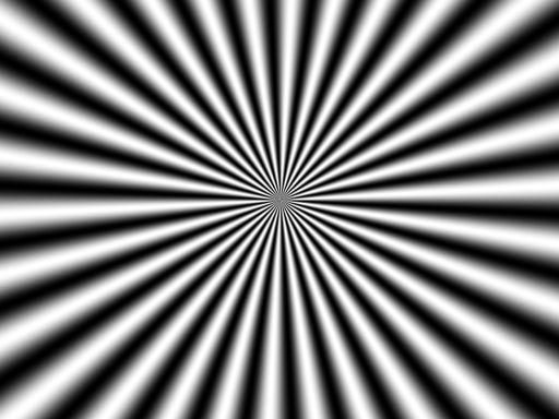
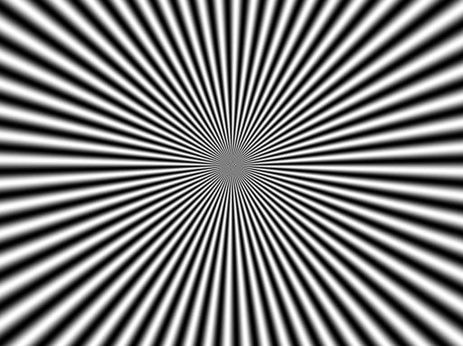
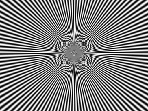
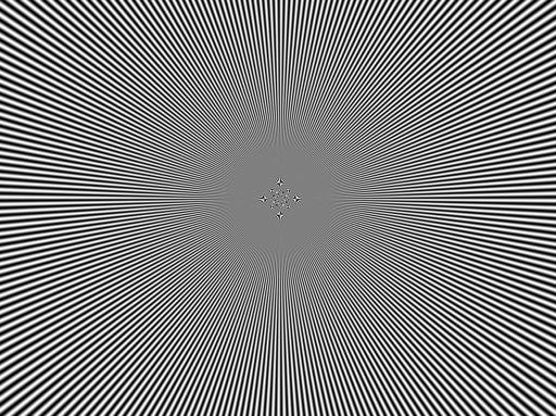
20 Target consisting of radial spokes Spatial frequency decreases outward Low spatial frequencies are faithfully recorded High spatial frequencies near the origin are corrupted Aliasing 2-d 21
21 22
22 23
23 24
24 25
25 26


26 Astronomical Detectors for Visible Light Most astronomical instruments use arrays of pixels to sample images Detectors based on the photoelectric effect Si is used for optical; band gap at 1.1 µm Si CCD (refers to how the photodiodes are read) 27
, In x Ga 1-x As (1.68 2.6 µm), Hg 1-x Cd x Te: (2.5 10 µm), InSb: 4.")
27 Astronomical Detectors for Infrared Semiconductors materials with smaller bandgaps are used for longer wavelengths Ge (1.6 µm), In x Ga 1-x As ( µm), Hg 1-x Cd x Te: ( µm), InSb: 4.6 µm Rockwell HgCdTe Arrays 2048 x x x x
28 The Good News:The Sampling Theorem So far only we only described the action of one pixel To construct an image we need to sample an array of points The Sampling Theorem tells us how close together those points have to be to record the signal with no loss of information 29
29 Sampling in Fourier Space Sampling in image space is described by multiplication with the bed-of-nails or Shah function III x j =# $ j ="# ( ) ( ) =! x " j 30
 The sampled function is III(x/*x)")
30 Sampling of a Continuous Function f(x) *x A continuous function f(x) is sampled by multiplication with III(x/*x) The sampled function is III(x/*x) f(x) 31
31 Sampling in Fourier Space In Fourier space the effect of sampling is to convolve the Fourier spectrum with the FT of III but FT{ f(x) III(x/*x) } = F(k) * FT{ III(x/*x) } Thus FT{ III(x) } = III (#) FT{ f(x) III(x/*x) } = *x F(k) * III(# *x) Sampling replicates the Fourier spectrum at a spatial frequency intervals equal to the sampling frequency 32
32 Sampling in Fourier Space Continuous function f(x) F(#) Band-limited Fourier spectrum Sampling function III(x/*x) # c *x III(# *x) 1/*x Over sampled III(x/*x) f(x) *x III(# *x)*f(#) Replicated spectrum Critically sampled # c 1/*x = 2# c # c Under sampled Aliased spectrum 33
33 The Sampling Theorem To record a band-limited signal with spectrum F(k) " 0; # # # c F(k) = 0; # > # c The sampling frequency must be 1/*x $ 2# c A sampled, band-limited signal can be reconstructed perfectly at any intermediate point by interpolation 34
34 The Sampling Theorem for AO Images For a diffraction-limited system the telescope pupil defines the bandlimit (slide 11) In spatial units (m -1 ) # c = D tel /%f = 1/%F In angular units (radian -1 ) # c = D tel /% 35
")
35 Keck AO Observations with NIRC2 NIRC2/LGS AO image of IC 10 Narrow camera (10 mas pixels) I/H/K 36
36 Observed Power Spectra for Keck AO Observed power spectrum - OTF 2 Diffraction limited information is evident Correction is better at the longer wavelength Only detector & sky noise at # > 0.8 # n 25 mas pixels would have been fine at K and 19 mas pixels H Could have greater FOV & if the noise is detector noise better SNR with coarser pixels 37

37 IC 10 color magnitude diagram from AO 38
38 AO CAMERAS
39 AO Cameras An AO camera images the focal plane at a spatial frequency that satisfies the sampling theorem Insures that all light collected by the telescope is relayed to the detector Provides a collimated beam for filters or other optical elements Conventional cameras, may correct residual telescope aberrations & thereby increase the field of view, e.g., prime focus corrector Controls background & stray light 40
40 Design Problems Physical pixel size may not be ideal Optical CCD's and infrared detector arrays have 10-40%µm pixels Detector noise depends on pixel size Small pixels have smaller dark current & read noise Arrays have limited size Typically for IR & for CCDs Over-sampling is expensive Trade spatial sampling & field of view 41
41 Diffraction Limited Sampling Cut off frequency of a diffraction limited system is 1/%F Nyquist sampling frequency is twice this: 2/%F Spatial sampling is *x = %F/2 For typical optical systems F & 15 Require *x = 15 µm wide pixels at % = 2 µm A camera that is well sampled at 2 µm will be severely under-sampled at 1 µm Need variable magnification with wavelength 42
42 Plate Scale Diffraction limit of a 10-m telescope at 1 µm %/D tel = 20 mas Nyquist sampling interval %/2D tel = 10 mas The plate scale is the angular scale at the focal plane S = 206,265/f [arc sec m -1 ] f = FD tel is the system focal length [m], D tel is the telescope diameter [m] and F is the system focal ratio 43
43 Plate Scale For example F/15 focus of Keck S = (F/15)(D tel /10 m) arc sec mm -1 or for *x wide pixels s = (F/15)(D tel /10 m)(*x/10 µm) mas pixel -1 The NIRC2 camera has three plate scales 10 mas 20 mas 40 mas Which one would you use at K band (2.2 µm)? 44
44 TELESOPES & FOCAL REDUCERS: Coupling Instruments To Telescopes
45 Two-Mirror Telescope! = m 2 k ( m + k "1) m = " s # s, magnification k, ratio mirror diameters s Secondary Primary Cassegrain two-mirror telescope with primary mirror focal length f 1 has an effective focal length of mf 1 46
46 Equivalent 1-Lens Telescope Two-Mirror Telescope = Equivalent 1- Lens Telescope with effective focal length f 47
47 Focal Reducers A focal reducer is an optical system that changes the final F-ratio From telescope 48
48 Focal Reducers A field lens at the telescope focus images the exit pupil of the telescope onto the aperture stop of the focal reducer Ensures that no light is lost at the collimator A collimator renders light parallel A camera images the light onto a focal plane detector Gratings or filters can be put in the space between the collimator and the camera 49
49 Geometry of Focal Reducers Telescope with primary mirror focal length f 1 Image is formed a distance f 1 * from the exit pupil Angle on the sky is!;%the angle at the exit pupil is / Diameter of the focal reducer elements depend on the FOV The diameter of the field lens is %2f!%, where f% is the effective telescope focal length and! is the angular radius of the FOV Equivalent 1- Lens Telescope f! = /f 1 * 50
50 Geometry of Focal Reducers If the aperture stop of the focal reducer is at the collimator lens and 0 is the angle at which the chief ray from the edge of the field enters the collimator then!f = /f 1 * = 0f col! angle on the sky f telescope focal length f col collimator focal length f 1 primary mirror focal length 51
51 Geometry of Focal Reducers The diameter of the collimator lens is found from the Lagrange invariant!d tel = 0D col 0 /! = f / f col = D tel / D col 52
52 Magnification The focal length of the telescope/focal reducer combination is the effective telescope focal length%f times the magnification of the focal reducer The magnification of the focal reducer is the ratio of the camera to collimator focal lengths The system focal length is the diameter of the telescope times the F-ratio of the camera 53
53 Focal Reducers: Example Keck/NIRC2, narrow camera has a magnification m = 3.66 D tel = 10 m, F narrow = = 55, *x = 27 µm pixels s = 206,265/(FD tel ) = 375 mas/mm *! = s *x = 0.01 arc sec/pixel The Nyquist frequency at 1 µm for 10-m telescope 2D tel /% = 100 arc sec -1 54
54 Focal Reducers: Example NIRC2 has three different magnifications to for: 10, 20, & 40 mas pixels Achieved by substituting the camera with one of different focal length 55
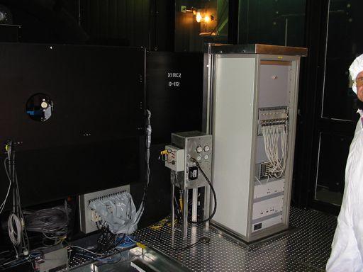
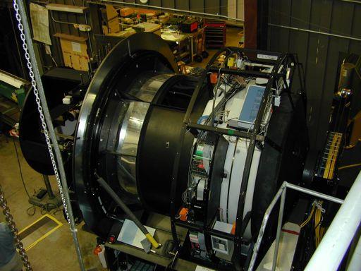
55 NIRC2 56

56 NIRC2: Inside the Black Box Camera module 57
57 Focal Reducer for the Infrared Collimator doubles as a field lens Forms an image of the telescope exit pupil at the aperture stop An aperture stop is placed between the collimator and camera lenses Distance between the collimator and camera equals f col +f cam 58
58 Focal Reducer for the Infrared A system with entrance & exit pupils at infinity is telecentric All the chief rays those that go through the center of the aperture stop emerge parallel to the optical axis Since a real image of the telescope exit pupil is found at the focal plane of the collimator, an aperture stop at this location precisely defines the acceptance angle of the focal reducer This stop is vital to rejecting unwanted thermal radiation from the telescope and sky 59
59 SPECTROGRAPHS
60 More Good News The majority of astronomical instruments are focal reducers Cameras Spectrographs Even AO systems! Focal reducers often host useful optical components Filters, polarizers, prisms, diffraction gratings, &c. 61
61 Spectrographs DEIMOS 62

62 DEIMOS Why are astronomical spectrographs so big? 63
63 Size Matters Astronomical spectrographs are huge because most are not diffraction limited, but seeinglimited Most astronomical spectrographs are dispersive dispersive spectrographs encode wavelength as position Image size determines spectral resolution To prevent light loss at the slit spectrograph size scales linearly with primary mirror diameter at constant spectral resolution Not true for interferometric spectrometers, e.g., Fourier transform spectrometers AO spectrographs can work at the diffraction limit and consequently are more compact 64
 Grating Gratings are favored Flexible Transmission or reflection Groove spacing Plane or powered surface Efficient Grating can be blazed")
64 Dispersive Spectrometers Dispersive spectrometers are a class of instruments that encode wavelength as position on a focal plane detector Dispersion can be caused by refraction or diffraction Key element is Prism (dn/d% " 0) Grating Gratings are favored Flexible Transmission or reflection Groove spacing Plane or powered surface Efficient Grating can be blazed Lightweight 65
65 Spectrometers as Imagers A dispersive spectrometer is fundamentally a device which makes an image of a source The position of the image encodes wavelength Typically the spectrometer makes an image of an aperture or slit In fiber fed spectrometers, the spectrometer makes an image of the light exiting an optical fiber The location and size of the image is determined jointly by the laws of geometric optics and the grating equation 66

66 Toy Spectrometer CCD 13 µm pixels Fiber source d = 100 µm Camera f = 200 mm 2! = 10 o Collimator f = 179 mm Filter wheel Grating! B = 64.5 o 1 = 12.5 µm 67
67 Schematic Spectrometer Collimator Camera p Fiber source f col 0 Grating 2 f cam CCD m! = " sin# $ sin% ( ) 68
68 Condition for Constructive Interference! m! = " sin# ± sin$ ( )!! Sign Convention Reflection grating: 0 & 2 have the same sign of they are on the same side of the grating normal. Transmission grating: 0 & 2 have the same sign if the diffracted ray crosses the normal.! sin"! sin" - for transmission + for reflection 69

69 Orders & Grating Blaze m = -2 m = -1 m = o m = 1 m = 2 27 o % = 633nm; 1/1 = 600 mm -1 70
70 Positional Encoding The angle 2 is given by the grating equation Image position set by the camera focal length Grating Camera p m! = " ( sin# + sin$ ) $ = arcsin(m! /" % sin#) 2 CCD p = f cam tan($) f cam 71
71 Mapping Wavelength to Angle Holding 0 and m constant, 2 varies with %! = arcsin( m" /# $ sin% ) 72
72 Mapping Wavelength to Position Holding 0 and m constant, p varies with % p = f CAM tan(! "! 0 ) /#p f CAM = 200 mm #p =13!m 73
73 Dispersion Dispersion gives the angular spread of diffraction, *2, for a source with wavelength spread, *% Using the grating equation, hold the angle of incidence, 0, and the order, m, constant m! = " sin# + sin$ ( ) m%! = " cos$%$ '&$ * ), (&! + #,m = m " 1 cos$ 74
74 Dispersion Over a limited range of wavelength dispersion is & constant Roughly linear relation between wavelength & position $!" ' & ) %!# ( *,m = m 1 + cos" 75
75 Dispersion With higher dispersion it is possible to distinguish closely spaced wavelengths High dispersion corresponds to High order (large m) Narrow grooves/high groove density Large 1/cos(2), i.e., oblique 2 close to!/2 $!" ' & ) %!# ( *,m = m + 1 cos" 76
76 Spectral Resolution 's Collimator Grating Camera CCD 'p Fiber source % 0 2 f col f cam %!" =!s/ f col,!# = $# ( ' * & $" ) +!",!p = f cam!# 77
77 Spectral Resolution: Diffraction Limit Even if the input is a point source, the image has a finite size on the CCD array, +p, due to diffraction The angular size of camera images, *2=%/D cam, limits the spectral resolution!" = #" #$!$ = % cos$ m!$!$ = " D cam R = " (sin& + sin$) =!" cos$ D cam " ' 2 D cam " tan( B 78
78 Spectral Resolution: the Diffraction Limit Telescope diameter does not enter into the formula! For our toy spectrograph D cam = 75 mm tan! B = 2 % = µm R DL! 470,000 79
79 Slit-Limited Spectral Resolution 's Collimator Grating Camera CCD Fiber source 'p 0 2 f col f cam %!" =!s/ f col,!# = $# ( ' * & $" ) +!",!p = f cam!# 80
80 Slit-Limited Spectral Resolution Generally, the source, is not a point If the extent is greater than the diffraction blur then the spectrometer resolution slit limited!" =!s f col %!# = $# ( ' * & $" ) %!# = $# ( ' * & $+ ) +,m ",m!" = cos" cos"!" = cos# cos#!+ = m, cos#!+ m cos"!s!+ = Hence, R SL = + sin" + sin# f = col, cos# cos# f col!+ cos"!s!s f col Which is bigger R DL or R SL? 81
81 Slit-Limited Spectral Resolution For the toy spectrograph the image size is set by the diameter of the fiber feed (100 µm) The resultant resolution is R SL & 11,500 or 1/40 of the diffraction limit For a spectrograph with slit width *& >> %/D tel and collimated beam diameter d col R SL = 2 d col tan! b D tel "# $ 83,000( d col 1m) ( D tel 10m) %1 ("# 1arc sec) %1 ( tan! b 2) The grating is d col tan(! b ) = 2 m long! 82
 = 2.")
82 HIRES on Keck The optics in high resolution, slitlimited spectrographs are huge For HIRES R*& = 39,000 tan(! b ) = inch collimated beam and 36-inch long grating mosaic 83
83 POLARIMETRY
84 Polarimetry Science Characterize the scattering properties of circumstellar material Polarization-based speckle suppression 85
85 Polarimetry & Scattering Consider a plane wave propagating in the z- direction, incident on a particle located at the origin The direction of the incident and scattered light defines the scattering plane The amplitude of the incident electric field, E i, can be written as a sum of E i// & E i3, parallel and perpendicular to the scattering plane The scattered field, E s, is decomposed into E s// & E s3 86
86 E i3 Scattering plane E i//! E s3 E s// 87
87 Polarimetry & Scattering The complex amplitude scattering matrix describes the relationship between E i and E s " $ # E s// E s! % & ' = eik r(z (ikr ( ) " S 2 S 3 %" $ ' $ # S 4 S 1 &# E i // E i! % ' & e.g., for Rayleigh scattering! S 2 S 3 $! # & = 'ik 3 r cos( 0 $ # & " S 4 S 1 % " 0 1% 88
88 Polarimetry: The Observables If we can measure S we can establish the nature of the scattering particle The phase function measures the angular variation of total intensity with scattering angle 2 I (! ) = E s// 2 + E s" # 1 ( 2 S S ) 1 Stokes I measures total intensity 89
89 Polarization If we measure the difference E s// 2 2! E s" # 1 ( 2 S 2 2 2! S ) 1 This is Stokes Q For isotropic particles S is diagonal If we have single scattering I & Q are all we need More generally we want U and possibly V U is needed to measure arbitrary linear polarization PA V measures circular polarization 90
90 Phase Function & Polarization by Spheres m = i; x = 2! a/% x = 0.1 x = 1 x = 4 x = 4 x = 1 x =

91 Polarization is a Key Diagnostic AU Mic Graham, Kalas & Matthews 2006 For edge-on disks polarimetry is essential Information about the phase function is lost because of averaging along the line of sight This information is recovered if Q and U are available because of the different angular dependence of the matrix elements of the complex amplitude scattering function 92
92 Measuring <cos!> and p max Simultaneous fit of surface brightness and polarization measures <cos!> and p max For AU Mic the data are consistent only with very porous grains, which means that they trace the primordial aggregation mechanism AU Mic Graham Kalas & Matthews
93 Polarimetry & Speckles Dual channel polarimetry suppresses common & noncommon path wavefront errors PSF+ PSF- PSF+ PSF- Stellar halo Q -Q Common WFE Non-common WFE 2Q Polarized astrophysical signal 94
94 Implementing a Polarimeter A polarimeter consists of a modulator and an analyzer The modulator changes some polarization property of the incident radiation The analyzer sorts the light according to its polarization state 95
95 Measuring Polarized Light The simplest polarimeter is a rotating linear polarizer: I (! ) = 1 2 ( I + Qcos2! + U sin2! ) Choose three angles and solve the resulting simultaneous equations, e.g., 0, 60, & 120 I = 2 ( 3 I + I + I ), Q = 2 ( 3 2I! I! I ), U = 2 ( 3 I! I ) 96
96 Polarimetry Components Retarder Introduces a phase delay between two perpendicular polarization states (e- and o-rays) Birefringent crystals e.g., rotating 1/4- and 1/2-wave quartz plates A rotating 1/2-wave plate rotates the plane of a linear polarized wave by 2& when the fast axis is rotated by & 97

97 1/2-wave plate 98

98 Polarimetry Components Analyzer HR polaroid Wire grids Polarizing beam splitters Wollaston Focal plane mask Needed for dual channel operation Half-plane mask/venetian blind Calibration system Calcite 99
99 Calibration Polarization calibration is tricky because Polarizing elements are not perfect, e.g., The waveplate retardance is not exactly half a wave The extinction of the analyzer is not 100% Orientations may not be at their nominal values Instrumental (de)polarization Diffraction (spiders) Non-normal reflections Telescope, relay optics, detector & dichroic beams splitters Birefringent optics (refractive elements) Polarization dependent wavefront errors! 100
100 Mueller Matrix Both calibrations are accomplished by measuring the 4. 4 elements of the system Mueller matrix! # # # # " I s Q s U s V s $! M 11 M 12 M 13 M 14 $! & # &# & M = # 21 M 22 M 23 M 24 &# & # M 31 M 32 M 33 M 34 &# & # &# % " M 41 M 42 M 43 M 44 %" Only seven of the 16 elements are independent, because the four complex matrix elements, S j, have four absolute values and three phase differences Spatial variation angles change with field angle Time dependent new configuration (%), image rotators, flexure I i Q i U i V i $ & & & & % 101
101 Data Reduction The system Mueller matrix for our simple polarizer consisting of a rotating wave plate and an ideal polarizer is M SYS (!," ) = M LP M ROT (#! )M WP (" )M ROT (! ) Using the top row of the system Mueller matrix the observed intensity is ( ) = I i + cos 2 2! j + sin 2 2! j cos" 2I O! j," ( )Q i + [ cos2! j sin2! ( 1# cos" )]U i + sin2! j sin"v i where the output intensity, I o (! j,&), is measured at angles j = 1, 2, 3, N 102
102 Data Reduction The column vector of measurements are related by a measurement matrix, M, to the input Stokes vector o! I 1 $! 1 cos 2 2' 1 + sin 2 2' 1 cos( cos2' 1 sin 2' 1 1 ) cos( # o I & # # 2 & o # I 3 & = 1 1 cos 2 2' 2 + sin 2 2' 2 cos( cos2' 2 sin 2' 2 1 ) cos( # # 1 cos 2 2' # & sin 2 2' 3 cos( cos2' 3 sin 2' 3 1 ) cos( # # & # o " I N % " 1 cos 2 2' N + sin 2 2' N cos( cos2' N sin 2' N 1 ) cos( Restating the last equation as ( ) sin 2' 1 sin( ( ) sin 2' 2 sin( ( ) sin 2' 3 sin( ( ) sin 2' N sin( the least squares estimate of S i corresponds to minimizing the norm e 2 2 = I o = M'S i I o i! M'S est which is found by using the pseudo-inverse of the measurement matrix $ &! & # & # & # & # " % I i Q i U i V i $ & & & & % i S est = ( M' T M' )!1 M' T I o 103
103 Acronyms & Glossary Aperture stop: an opening that determines the amount of light which passes through an optical system to the image, usually the boundary of the primary mirror. Cassegrain telescope: a two mirror telescope with a convex secondary Chief ray: any ray from an off-axis object point which passes through the center of the aperture stop of an optical system. The chief ray enters the optical system along a line directed toward the midpoint of the entrance pupil, and leaves the system along a line passing through the center of the exit pupil Entrance pupil: the image of the aperture stop. If there is no physical aperture stop, the entrance pupil is an image of the lens or mirror itself. Exit pupil: is a virtual aperture in an optical system. Only rays that pass through the exit pupil can exit the system. The exit pupil is the image of the aperture stop in the optics that follow it. Fourier transform: F(#)=( f(x) exp(-2!i # x) dx FOV: field of view Gregorian telescope: a two mirror telescope with a concave secondary Influence function: shape adopted by the surface of a deformable mirror when a single actuator is exercised. OTF: the optical transfer function. The spatial frequency response of a system to a single harmonic stimulus. Fourier transform of the PSF. Mueller Matrix: a 4.4 real matrix describes how optical elements modify the Stokes vector. PSF: the spatial response of a system to a point source. Shah function: The sampling function or bed of nails III(x) = )*(x-j) sinc(x) = sin(x)/x Bracewell s definition includes!, i,e., sin(!x)/!x Stokes Vector: (I, Q, U, V) a basis set for describing partially polarized incoherent light. Q & U describe linear polarization, and V describes circular polarization. Structure function: D " (r) =< "(x) - " (x+r) 2 > Top hat function:,(x) = 1, x <1/2, otherwise 0 Telecentric: a system with entrance & exit pupils at infinity 104
CfAO Summer School 2009: Astronomical Instrumentation for Adaptive Optics
 CfAO Summer School 2009: Astronomical Instrumentation for Adaptive Optics James R. Graham University of California, Berkeley Outline What s special about AO instruments? Spatial information in AO corrected
High-Resolution Imagers
 40 Telescopes and Imagers High-Resolution Imagers High-resolution imagers look at very small fields of view with diffraction-limited angular resolution. As the field is small, intrinsic aberrations are
Real Telescopes & Cameras. Stephen Eikenberry 05 October 2017
 Lecture 7: Real Telescopes & Cameras Stephen Eikenberry 05 October 2017 Real Telescopes Research observatories no longer build Newtonian or Parabolic telescopes for optical/ir astronomy Aberrations from
Astronomy 203 practice final examination
 Astronomy 203 practice final examination Fall 1999 If this were a real, in-class examination, you would be reminded here of the exam rules, which are as follows: You may consult only one page of formulas
Astr 2310 Thurs. March 3, 2016 Today s Topics
 Astr 2310 Thurs. March 3, 2016 Today s Topics Chapter 6: Telescopes and Detectors Optical Telescopes Simple Optics and Image Formation Resolution and Magnification Invisible Astronomy Ground-based Radio
Astronomical Optics. Second Edition DANIEL J. SCHROEDER ACADEMIC PRESS
 Astronomical Optics Second Edition DANIEL J. SCHROEDER Professor of Physics and Astronomy, Emeritus Department of Physics and Astronomy Beloit College, Beloit, Wisconsin ACADEMIC PRESS A Harcourt Science
Optical/IR Observational Astronomy Telescopes I: Telescope Basics. David Buckley, SAAO
 David Buckley, SAAO 27 Feb 2012 1 Some other Telescope Parameters 1. Plate Scale This defines the scale of an image at the telescopes focal surface For a focal plane, with no distortion, this is just related
Spectroscopy. Stephen Eikenberry (U. Florida) Dunlap Institute Summer School 25 July 2018
 Dunlap Institute Summer School 25 July 2018") Spectroscopy Stephen Eikenberry (U. Florida) Dunlap Institute Summer School 25 July 2018 Observational Astronomy What? Astronomy gathers the vast majority of its information from the LIGHT emitted by astrophysical
Spectroscopy Stephen Eikenberry (U. Florida) Dunlap Institute Summer School 25 July 2018 Observational Astronomy What? Astronomy gathers the vast majority of its information from the LIGHT emitted by astrophysical
Overview: Astronomical Spectroscopy
 Overview: Astronomical Spectroscopy or How to Start Thinking Creatively about Measuring the Universe Basic Spectrograph Optics Objective Prism Spectrometers - AESoP Slit Spectrometers Spectrometers for
Problem Solving. radians. 180 radians Stars & Elementary Astrophysics: Introduction Press F1 for Help 41. f s. picture. equation.
 Problem Solving picture θ f = 10 m s =1 cm equation rearrange numbers with units θ factors to change units s θ = = f sinθ fθ = s / cm 10 m f 1 m 100 cm check dimensions 1 3 π 180 radians = 10 60 arcmin
These notes may contain copyrighted material! They are for your own use only during this course.
 Licensed for Personal Use Only DO NOT DISTRIBUTE These notes may contain copyrighted material! They are for your own use only during this course. Distributing them in anyway will be considered a breach
September 14, Monday 4. Tools for Solar Observations-II
 September 14, Monday 4. Tools for Solar Observations-II Spectrographs. Measurements of the line shift. Spectrograph Most solar spectrographs use reflection gratings. a(sinα+sinβ) grating constant Blazed
Optical/NIR Spectroscopy A3130. John Wilson Univ of Virginia
 Optical/NIR Spectroscopy A3130 John Wilson Univ of Virginia Topics: Photometry is low resolution spectroscopy Uses of spectroscopy in astronomy Data cubes and dimensionality challenge Spectrograph design
Introduction to Interferometer and Coronagraph Imaging
 Introduction to Interferometer and Coronagraph Imaging Wesley A. Traub NASA Jet Propulsion Laboratory and Harvard-Smithsonian Center for Astrophysics Michelson Summer School on Astrometry Caltech, Pasadena
2001 Spectrometers. Instrument Machinery. Movies from this presentation can be access at
 2001 Spectrometers Instrument Machinery Movies from this presentation can be access at http://www.shsu.edu/~chm_tgc/sounds/sound.html Chp20: 1 Optical Instruments Instrument Components Components of various
First observations of the second solar spectrum with spatial resolution at the Lunette Jean Rösch
 First observations of the second solar spectrum with spatial resolution at the Lunette Jean Rösch Malherbe, J.-M., Moity, J., Arnaud, J., Roudier, Th., July 2006 The experiment setup in spectroscopic mode
Lecture 8: Polarimetry 2. Polarizers and Retarders. Polarimeters. Scattering Polarization. Zeeman Effect. Outline
 Lecture 8: Polarimetry 2 Outline 1 Polarizers and Retarders 2 Polarimeters 3 Scattering Polarization 4 Zeeman Effect Christoph U. Keller, Utrecht University, C.U.Keller@uu.nl Observational Astrophysics
Astronomy. Optics and Telescopes
 Astronomy A. Dayle Hancock adhancock@wm.edu Small 239 Office hours: MTWR 10-11am Optics and Telescopes - Refraction, lenses and refracting telescopes - Mirrors and reflecting telescopes - Diffraction limit,
1. Give short answers to the following questions. a. What limits the size of a corrected field of view in AO?
 Astronomy 418/518 final practice exam 1. Give short answers to the following questions. a. What limits the size of a corrected field of view in AO? b. Describe the visibility vs. baseline for a two element,
Chapter 6 Telescopes: Portals of Discovery
 Chapter 6 Telescopes: Portals of Discovery 6.1 Eyes and Cameras: Everyday Light Sensors Our goals for learning: How does your eye form an image? How do we record images? How does your eye form an image?
Astronomical Techniques
 Astronomical Techniques Spectrographs & Spectroscopy Spectroscopy What is spectroscopy? A little history. What can we learn from spectroscopy? Play with simple spectrographs. Basic optics of a spectrograph.
Optical/IR Observational Astronomy Telescopes I: Telescope Basics. David Buckley, SAAO
 David Buckley, SAAO 17 Feb 2010 1 Some other Telescope Parameters 1. Plate Scale This defines the scale of an image at the telescopes focal surface For a focal plane, with no distortion, this is just related
solar telescopes Solar Physics course lecture 5 Feb Frans Snik BBL 707
 Solar Physics course lecture 5 Feb 19 2008 Frans Snik BBL 707 f.snik@astro.uu.nl www.astro.uu.nl/~snik solar vs. nighttime telescopes solar constant: 1.37 kw/m 2 destroys optics creates seeing solar vs.
2.71. Final examination. 3 hours (9am 12 noon) Total pages: 7 (seven) PLEASE DO NOT TURN OVER UNTIL EXAM STARTS PLEASE RETURN THIS BOOKLET
 Total pages: 7 (seven) PLEASE DO NOT TURN OVER UNTIL EXAM STARTS PLEASE RETURN THIS BOOKLET") 2.71 Final examination 3 hours (9am 12 noon) Total pages: 7 (seven) PLEASE DO NOT TURN OVER UNTIL EXAM STARTS Name: PLEASE RETURN THIS BOOKLET WITH YOUR SOLUTION SHEET(S) MASSACHUSETTS INSTITUTE OF TECHNOLOGY
2.71 Final examination 3 hours (9am 12 noon) Total pages: 7 (seven) PLEASE DO NOT TURN OVER UNTIL EXAM STARTS Name: PLEASE RETURN THIS BOOKLET WITH YOUR SOLUTION SHEET(S) MASSACHUSETTS INSTITUTE OF TECHNOLOGY
Optics and Telescopes
 Optics and Telescopes Guiding Questions 1. Why is it important that telescopes be large? 2. Why do most modern telescopes use a large mirror rather than a large lens? 3. Why are observatories in such remote
Error Budgets, and Introduction to Class Projects. Lecture 6, ASTR 289
 Error Budgets, and Introduction to Class Projects Lecture 6, ASTR 89 Claire Max UC Santa Cruz January 8, 016 Page 1 What is residual wavefront error? Telescope AO System Science Instrument Very distorted
Telescopes: Portals of Discovery
 Telescopes: Portals of Discovery How do light and matter interact? Emission Absorption Transmission Transparent objects transmit light Opaque objects block (absorb) light Reflection or Scattering Reflection
Chapter 6 Telescopes: Portals of Discovery. Agenda. How does your eye form an image? Refraction. Example: Refraction at Sunset
 Chapter 6 Telescopes: Portals of Discovery Agenda Announce: Read S2 for Thursday Ch. 6 Telescopes 6.1 Eyes and Cameras: Everyday Light Sensors How does your eye form an image? Our goals for learning How
Observational methods for astrophysics. Pierre Hily-Blant
 Observational methods for astrophysics Pierre Hily-Blant IPAG pierre.hily-blant@univ-grenoble-alpes.fr, OSUG-D/306 2016-17 P. Hily-Blant (Master2 APP) Observational methods 2016-17 1 / 323 VI Spectroscopy
Lecture 7: Optical Spectroscopy. Astrophysical Spectroscopy. Broadband Filters. Fabry-Perot Filters. Interference Filters. Prism Spectrograph
 Lecture 7: Optical Spectroscopy Outline 1 Astrophysical Spectroscopy 2 Broadband Filters 3 Fabry-Perot Filters 4 Interference Filters 5 Prism Spectrograph 6 Grating Spectrograph 7 Fourier Transform Spectrometer
CanariCam-Polarimetry: A Dual-Beam 10 µm Polarimeter for the GTC
 Astronomical Polarimetry: Current Status and Future Directions ASP Conference Series, Vol. 343, 2005 Adamson, Aspin, Davis, and Fujiyoshi CanariCam-Polarimetry: A Dual-Beam 10 µm Polarimeter for the GTC
Final examination. 3 hours (9am 12 noon) Total pages: 7 (seven) PLEASE DO NOT TURN OVER UNTIL EXAM STARTS PLEASE RETURN THIS BOOKLET
 Total pages: 7 (seven) PLEASE DO NOT TURN OVER UNTIL EXAM STARTS PLEASE RETURN THIS BOOKLET") 2.710 Final examination 3 hours (9am 12 noon) Total pages: 7 (seven) PLEASE DO NOT TURN OVER UNTIL EXAM STARTS Name: PLEASE RETURN THIS BOOKLET WITH YOUR SOLUTION SHEET(S) MASSACHUSETTS INSTITUTE OF TECHNOLOGY
2.710 Final examination 3 hours (9am 12 noon) Total pages: 7 (seven) PLEASE DO NOT TURN OVER UNTIL EXAM STARTS Name: PLEASE RETURN THIS BOOKLET WITH YOUR SOLUTION SHEET(S) MASSACHUSETTS INSTITUTE OF TECHNOLOGY
Exoplanets Direct imaging. Direct method of exoplanet detection. Direct imaging: observational challenges
 Black body flux (in units 10-26 W m -2 Hz -1 ) of some Solar System bodies as seen from 10 pc. A putative hot Jupiter is also shown. The planets have two peaks in their spectra. The short-wavelength peak
7. Telescopes: Portals of Discovery Pearson Education Inc., publishing as Addison Wesley
 7. Telescopes: Portals of Discovery Parts of the Human Eye pupil allows light to enter the eye lens focuses light to create an image retina detects the light and generates signals which are sent to the
PRINCIPLES OF PHYSICAL OPTICS
 PRINCIPLES OF PHYSICAL OPTICS C. A. Bennett University of North Carolina At Asheville WILEY- INTERSCIENCE A JOHN WILEY & SONS, INC., PUBLICATION CONTENTS Preface 1 The Physics of Waves 1 1.1 Introduction
Speckles and adaptive optics
 Chapter 9 Speckles and adaptive optics A better understanding of the atmospheric seeing and the properties of speckles is important for finding techniques to reduce the disturbing effects or to correct
Diffraction gratings. B.Tech-I
 Diffraction gratings B.Tech-I Introduction Diffraction grating can be understood as an optical unit that separates polychromatic light into constant monochromatic composition. Uses are tabulated below
NEON Archive School 2006
 NEON Archive School 2006 Introduction to Spectroscopic Techniques (low dispersion) M. Dennefeld (IAP-Paris) Outline Basic optics of gratings and spectrographs (with emphasis on long-slit spectroscopy)
Astro 500 A500/L-15 1
 Astro 500 A500/L-15 1 Lecture Outline Spectroscopy from a 3D Perspective ü Basics of spectroscopy and spectrographs ü Fundamental challenges of sampling the data cube Approaches and example of available
Why Use a Telescope?
 1 Why Use a Telescope? All astronomical objects are distant so a telescope is needed to Gather light -- telescopes sometimes referred to as light buckets Resolve detail Magnify an image (least important
How Light Beams Behave. Light and Telescopes Guiding Questions. Telescopes A refracting telescope uses a lens to concentrate incoming light at a focus
 Light and Telescopes Guiding Questions 1. Why is it important that telescopes be large? 2. Why do most modern telescopes use a large mirror rather than a large lens? 3. Why are observatories in such remote
Sky Projected Shack-Hartmann Laser Guide Star
 Sky Projected Shack-Hartmann Laser Guide Star T. Butterley a, D.F. Buscher b, G. D. Love a, T.J. Morris a, R. M. Myers a and R. W. Wilson a a University of Durham, Dept. of Physics, Rochester Building,
An Introduction to. Adaptive Optics. Presented by. Julian C. Christou Gemini Observatory
 An Introduction to Adaptive Optics Presented by Julian C. Christou Gemini Observatory Gemini North in action Turbulence An AO Outline Atmospheric turbulence distorts plane wave from distant object. How
PAPER 338 OPTICAL AND INFRARED ASTRONOMICAL TELESCOPES AND INSTRUMENTS
 MATHEMATICAL TRIPOS Part III Monday, 12 June, 2017 1:30 pm to 3:30 pm PAPER 338 OPTICAL AND INFRARED ASTRONOMICAL TELESCOPES AND INSTRUMENTS Attempt no more than TWO questions. There are THREE questions
September 9, Wednesday 3. Tools for Solar Observations-I
 September 9, Wednesday 3. Tools for Solar Observations-I Solar telescopes. Resolution, MTF, seeing. High resolution telescopes. Spectrographs. Types of Solar Observations Electro-magnetic observations
Phys102 Lecture Diffraction of Light
 Phys102 Lecture 31-33 Diffraction of Light Key Points Diffraction by a Single Slit Diffraction in the Double-Slit Experiment Limits of Resolution Diffraction Grating and Spectroscopy Polarization References
AS 101: Day Lab #2 Summer Spectroscopy
 Spectroscopy Goals To see light dispersed into its constituent colors To study how temperature, light intensity, and light color are related To see spectral lines from different elements in emission and
Talk about. Optical Telescopes and Instrumentation. by Christian Clemens
 Talk about Optical Telescopes and Instrumentation by Christian Clemens Overview powers of telescopes lens refractors, mirror reflectors interferometry, spectroscopy, optical systems modern observatories
Telescopes. Lecture 7 2/7/2018
 Telescopes Lecture 7 2/7/2018 Tools to measure electromagnetic radiation Three essentials for making a measurement: A device to collect the radiation A method of sorting the radiation A device to detect
Solar Magnetic Fields Jun 07 UA/NSO Summer School 1
 Solar Magnetic Fields 2 12 Jun 07 UA/NSO Summer School 1 Solar Magnetic Fields 2 (12 June) An introduction to the instruments and techniques used to remotely measure the solar magnetic field Stokes Vectors
Universe. Chapter 6. Optics and Telescopes 11/16/2014. By reading this chapter, you will learn. Tenth Edition
 Roger Freedman Robert Geller William Kaufmann III Universe Tenth Edition Chapter 6 Optics and Telescopes By reading this chapter, you will learn 6 1 How a refracting telescope uses a lens to form an image
Spectroscopy. Stephen Eikenberry (U. Florida) Dunlap Institute Summer School 26 July 2017
 Dunlap Institute Summer School 26 July 2017") Spectroscopy Stephen Eikenberry (U. Florida) Dunlap Institute Summer School 26 July 2017 Spectroscopy: What is it? How Bright? (our favorite question): Versus position on the sky Versus wavelength/energy
Spectroscopy Stephen Eikenberry (U. Florida) Dunlap Institute Summer School 26 July 2017 Spectroscopy: What is it? How Bright? (our favorite question): Versus position on the sky Versus wavelength/energy
Lecture 9: Speckle Interferometry. Full-Aperture Interferometry. Labeyrie Technique. Knox-Thompson Technique. Bispectrum Technique
 Lecture 9: Speckle Interferometry Outline 1 Full-Aperture Interferometry 2 Labeyrie Technique 3 Knox-Thompson Technique 4 Bispectrum Technique 5 Differential Speckle Imaging 6 Phase-Diverse Speckle Imaging
Telescopes (Chapter 6)
") Telescopes (Chapter 6) Based on Chapter 6 This material will be useful for understanding Chapters 7 and 10 on Our planetary system and Jovian planet systems Chapter 5 on Light will be useful for understanding
Telescopes (Chapter 6) Based on Chapter 6 This material will be useful for understanding Chapters 7 and 10 on Our planetary system and Jovian planet systems Chapter 5 on Light will be useful for understanding
The science of light. P. Ewart
 The science of light P. Ewart Oxford Physics: Second Year, Optics Parallel reflecting surfaces t images source Extended source path difference xcos 2t=x Fringes localized at infinity Circular fringe constant
Telescopes. Astronomy 320 Wednesday, February 14, 2018
 Telescopes Astronomy 320 Wednesday, February 14, 2018 Telescopes gather light and resolve detail A telescope is sometimes called a light bucket. Number of photons collected per second is proportional to
On the FPA infrared camera transfer function calculation
 On the FPA infrared camera transfer function calculation (1) CERTES, Université Paris XII Val de Marne, Créteil, France (2) LTM, Université de Bourgogne, Le Creusot, France by S. Datcu 1, L. Ibos 1,Y.
Lecture 6: Polarimetry 2. Polarizers and Retarders. Polarimeters. Scattering Polarization. Zeeman Effect. Hanle Effect. Outline
 Lecture 6: Polarimetry 2 Outline 1 Polarizers and Retarders 2 Polarimeters 3 Scattering Polarization 4 Zeeman Effect 5 Hanle Effect Christoph U. Keller, Utrecht University, C.U.Keller@uu.nl Solar Physics,
POSITION SENSITIVE DETECTORS - 8. Dept. Physics & Astronomy
 POSITION SENSITIVE DETECTORS - 8 Optical and IR Applications in Astronomy and Astrophysics Ian S. McLean Dept. Physics & Astronomy University it of California, i Los Angeles INTRODUCTION 400 th anniversary
Engineering Physics 1 Prof. G.D. Vermaa Department of Physics Indian Institute of Technology-Roorkee
 Engineering Physics 1 Prof. G.D. Vermaa Department of Physics Indian Institute of Technology-Roorkee Module-04 Lecture-02 Diffraction Part - 02 In the previous lecture I discussed single slit and double
3/7/2018. Light and Telescope. PHYS 1411 Introduction to Astronomy. Topics for Today s class. What is a Telescopes?
 PHYS 1411 Introduction to Astronomy Light and Telescope Chapter 6 Topics for Today s class Optical Telescopes Big Telescopes Advances in Telescope Designs Telescopes Mountings Problems with Mirrors and
Fully achromatic nulling interferometer (FANI) for high SNR exoplanet characterization
 for high SNR exoplanet characterization") Fully achromatic nulling interferometer (FANI) for high SNR exoplanet characterization François Hénault Institut de Planétologie et d Astrophysique de Grenoble Université Joseph Fourier Centre National
Fully achromatic nulling interferometer (FANI) for high SNR exoplanet characterization François Hénault Institut de Planétologie et d Astrophysique de Grenoble Université Joseph Fourier Centre National
Exoplanets Direct imaging. Direct method of exoplanet detection. Direct imaging: observational challenges
 Black body flux (in units 10-26 W m -2 Hz -1 ) of some Solar System bodies as seen from 10 pc. A putative hot Jupiter is also shown. The planets have two peaks in their spectra. The short-wavelength peak
EXPOSURE TIME ESTIMATION
 ASTR 511/O Connell Lec 12 1 EXPOSURE TIME ESTIMATION An essential part of planning any observation is to estimate the total exposure time needed to satisfy your scientific goal. General considerations
Final Announcements. Lecture25 Telescopes. The Bending of Light. Parts of the Human Eye. Reading: Chapter 7. Turn in the homework#6 NOW.
 Final Announcements Turn in the homework#6 NOW. Homework#5 and Quiz#6 will be returned today. Today is the last lecture. Lecture25 Telescopes Reading: Chapter 7 Final exam on Thursday Be sure to clear
Light and Telescope 3/4/2018. PHYS 1403 Introduction to Astronomy. Guideposts (cont d.) Guidepost. Outline (continued) Outline.
 Guidepost. Outline (continued) Outline.") PHYS 1403 Introduction to Astronomy Light and Telescope Chapter 6 Guidepost In this chapter, you will consider the techniques astronomers use to study the Universe What is light? How do telescopes work?
PHYS 1403 Introduction to Astronomy Light and Telescope Chapter 6 Guidepost In this chapter, you will consider the techniques astronomers use to study the Universe What is light? How do telescopes work?
The GMT Consortium Large Earth Finder. Sagi Ben-Ami Smithsonian Astrophysical Observatory
 The GMT Consortium Large Earth Finder Sagi Ben-Ami Smithsonian Astrophysical Observatory The Giant Magellan Telescope The GMT is one of the three next generation optical telescope. Segmented Gregorian
Wavefront errors due to atmospheric turbulence Claire Max
 Wavefront errors due to atmospheric turbulence Claire Max Page 1 Kolmogorov turbulence, cartoon solar Outer scale L 0 Inner scale l 0 h Wind shear convection h ground Page Atmospheric Turbulence generally
Optical/IR Observational Astronomy Telescopes I: Optical Principles. David Buckley, SAAO. 24 Feb 2012 NASSP OT1: Telescopes I-1
 David Buckley, SAAO 24 Feb 2012 NASSP OT1: Telescopes I-1 1 What Do Telescopes Do? They collect light They form images of distant objects The images are analyzed by instruments The human eye Photographic
Chapter 5 Telescopes
 Chapter 5 Telescopes Units of Chapter 5 Telescope Design Images and Detectors The Hubble Space Telescope Telescope Size High-Resolution Astronomy Radio Astronomy Interferometry Space-Based Astronomy Full-Spectrum
Name Final Exam May 1, 2017
 Name Final Exam May 1, 217 This test consists of five parts. Please note that in parts II through V, you can skip one question of those offered. Some possibly useful formulas appear below. Constants, etc.
Electronic Imaging in Astronomy
 Ian S, McLean Electronic Imaging in Astronomy Detectors and Instrumentation (Second Edition) j""v Published f udiisnea in association with witn fyj Springer Praxis PubUshing Publisl PR Chichester, UK Contents
CHAPTER IV INSTRUMENTATION: OPTICAL TELESCOPE
 CHAPTER IV INSTRUMENTATION: OPTICAL TELESCOPE Outline: Main Function of Telescope Types of Telescope and Optical Design Optical Parameters of Telescope Light gathering power Magnification Resolving power
1 Lecture, 2 September 1999
 1 Lecture, 2 September 1999 1.1 Observational astronomy Virtually all of our knowledge of astronomical objects was gained by observation of their light. We know how to make many kinds of detailed measurements
Refraction is the bending of light when it passes from one substance into another. Your eye uses refraction to focus light.
 Telescopes Portals of Discovery Chapter 6 Lecture The Cosmic Perspective 6.1 Eyes and Cameras: Everyday Light Sensors How do eyes and cameras work? Seventh Edition Telescopes Portals of Discovery The Eye
Optics and Telescope. Chapter Six
 Optics and Telescope Chapter Six ASTR 111 003 Fall 2007 Lecture 06 Oct. 09, 2007 Introduction To Modern Astronomy I: Solar System Introducing Astronomy (chap. 1-6) Planets and Moons (chap. 7-15) Chap.
CHIRON efficiency. A. Tokovinin. Version 2. March 28, 2011 file: prj/bme/chiron/commissioning/efficiency.tex
 CHIRON efficiency A. Tokovinin Version 2. March 28, 2011 file: prj/bme/chiron/commissioning/efficiency.tex 1 Estimated CHIRON efficiency In this Section, the estimate of the total efficiency of CHIRON
Polarimetry Techniques. K. Sankarasubramanian ISRO Satellite Centre Bangalore India
 Polarimetry Techniques K. Sankarasubramanian ISRO Satellite Centre Bangalore sankark@isac.gov.in Outline Introduction Why Polarimetry? Requirements Polarization Basics Stokes Parameters & Mueller Matrices
Light and Telescope 10/20/2017. PHYS 1411 Introduction to Astronomy. Guideposts (cont d.) Guidepost. Outline (continued) Outline.
 Guidepost. Outline (continued) Outline.") PHYS 1411 Introduction to Astronomy Light and Telescope Chapter 6 Guidepost In this chapter, you will consider the techniques astronomers use to study the Universe What is light? How do telescopes work?
PHYS 1411 Introduction to Astronomy Light and Telescope Chapter 6 Guidepost In this chapter, you will consider the techniques astronomers use to study the Universe What is light? How do telescopes work?
DAY LABORATORY EXERCISE: SPECTROSCOPY
 AS101 - Day Laboratory: Spectroscopy Page 1 DAY LABORATORY EXERCISE: SPECTROSCOPY Goals: To see light dispersed into its constituent colors To study how temperature, light intensity, and light color are
Lecture 4: Polarimetry 2. Polarizers and Retarders. Polarimeters. Scattering Polarization. Zeeman Effect. Outline
 Lecture 4: Polarimetry 2 Outline 1 Polarizers and Retarders 2 Polarimeters 3 Scattering Polarization 4 Zeeman Effect Christoph U. Keller, Utrecht University, C.U.Keller@uu.nl Observational Astrophysics
Universe. Chapter 6. Optics and Telescopes 8/12/2015. By reading this chapter, you will learn. Tenth Edition
 Roger Freedman Robert Geller William Kaufmann III Universe Tenth Edition Chapter 6 Optics and Telescopes By reading this chapter, you will learn 6 1 How a refracting telescope uses a lens to form an image
Chapter 5. Telescopes. Copyright (c) The McGraw-Hill Companies, Inc. Permission required for reproduction or display.
 The McGraw-Hill Companies, Inc. Permission required for reproduction or display.") Chapter 5 Telescopes Copyright (c) The McGraw-Hill Companies, Inc. Permission required for reproduction or display. Tools of the Trade: Telescopes The Powers of a Telescope Collecting Power Bigger telescope,
Chapter 5 Telescopes Copyright (c) The McGraw-Hill Companies, Inc. Permission required for reproduction or display. Tools of the Trade: Telescopes The Powers of a Telescope Collecting Power Bigger telescope,
Application of Precision Deformable Mirrors to Space Astronomy
 Application of Precision Deformable Mirrors to Space Astronomy John Trauger, Dwight Moody Brian Gordon, Yekta Gursel (JPL) Mark Ealey, Roger Bagwell (Xinetics) Workshop on Innovative Designs for the Next
Report to the GSMT Committee
 Report to the GSMT Committee P. McCarthy GMT Science Working Group and GMT Board GMT Consortium Status Conceptual Design Review AO Systems GMT Instrument Candidates Instrument properties Potential scientific
PHY410 Optics Exam #3
 PHY410 Optics Exam #3 NAME: 1 2 Multiple Choice Section - 5 pts each 1. A continuous He-Ne laser beam (632.8 nm) is chopped, using a spinning aperture, into 500 nanosecond pulses. Compute the resultant
Nature of Light Part 2
 Nature of Light Part 2 Fresnel Coefficients From Helmholts equation see imaging conditions for Single lens 4F system Diffraction ranges Rayleigh Range Diffraction limited resolution Interference Newton
Assignment 3 Due September 27, 2010
 Assignment 3 Due September 27, 2010 Text readings Stops section 5.3 Dispersing and Reflecting Prisms [sections 5.5.1 and 5.5.2] Optical systems section 5.7 Lens Aberrations [section 6.3] Be careful about
Modern Observational/Instrumentation Techniques Astronomy 500
 Modern Observational/Instrumentation Techniques Astronomy 500 Andy Sheinis, Sterling 5520,2-0492 sheinis@astro.wisc.edu MW 2:30, 6515 Sterling Office Hours: Tu 11-12 Hardware 1 Telescopes What parameters
The science of light. P. Ewart
 The science of light P. Ewart Lecture notes: On web site NB outline notes! Textbooks: Hecht, Klein and Furtak, Lipson, Lipson and Lipson, Optical Physics Brooker, Modern Classical Problems: Material for
Adaptive Optics for the Giant Magellan Telescope. Marcos van Dam Flat Wavefronts, Christchurch, New Zealand
 Adaptive Optics for the Giant Magellan Telescope Marcos van Dam Flat Wavefronts, Christchurch, New Zealand How big is your telescope? 15-cm refractor at Townsend Observatory. Talk outline Introduction
What are the most important properties of a telescope? Chapter 6 Telescopes: Portals of Discovery. What are the two basic designs of telescopes?
 Chapter 6 Telescopes: Portals of Discovery What are the most important properties of a telescope? 1. Light-collecting area: Telescopes with a larger collecting area can gather a greater amount of light
Chapter 6 Lecture. The Cosmic Perspective. Telescopes Portals of Discovery Pearson Education, Inc.
 Chapter 6 Lecture The Cosmic Perspective Telescopes Portals of Discovery 2014 Pearson Education, Inc. Telescopes Portals of Discovery CofC Observatory 6.1 Eyes and Cameras: Everyday Light Sensors Our goals
Chapter 6 Lecture. The Cosmic Perspective Seventh Edition. Telescopes Portals of Discovery Pearson Education, Inc.
 Chapter 6 Lecture The Cosmic Perspective Seventh Edition Telescopes Portals of Discovery Telescopes Portals of Discovery 6.1 Eyes and Cameras: Everyday Light Sensors Our goals for learning: How do eyes
Ground- and Space-Based Telescopes. Dr. Vithal Tilvi
 Ground- and Space-Based Telescopes Dr. Vithal Tilvi Telescopes and Instruments Astronomers use telescopes to gather light from distant objects and instruments to record the data Telescopes gather light
Light and Telescope 10/22/2018. PHYS 1403 Introduction to Astronomy. Reminder/Announcement. Chapter Outline. Chapter Outline (continued)
") PHYS 1403 Introduction to Astronomy Light and Telescope Chapter 6 Reminder/Announcement 1. Extension for Term Project 1: Now Due on Monday November 12 th 2. You will be required to bring your cross staff
PHYS 1403 Introduction to Astronomy Light and Telescope Chapter 6 Reminder/Announcement 1. Extension for Term Project 1: Now Due on Monday November 12 th 2. You will be required to bring your cross staff
Optics.
 Optics www.optics.rochester.edu/classes/opt100/opt100page.html Course outline Light is a Ray (Geometrical Optics) 1. Nature of light 2. Production and measurement of light 3. Geometrical optics 4. Matrix
Lecture 5: Polarization. Polarized Light in the Universe. Descriptions of Polarized Light. Polarizers. Retarders. Outline
 Lecture 5: Polarization Outline 1 Polarized Light in the Universe 2 Descriptions of Polarized Light 3 Polarizers 4 Retarders Christoph U. Keller, Leiden University, keller@strw.leidenuniv.nl ATI 2016,
How do they work? Chapter 5
 Telescopes How do they work? Chapter 5 1. History 2. Lenses & Hardware 3. Reflecting Telescopes 4. Refracting Telescopes History Hans Lippershey Middleburg, Holland invented the refractor telescope in
Lecture 2: Basic Astronomical Optics. Prisms, Lenses, and Mirrors
 Lecture 2: Basic Astronomical Optics Prisms, Lenses, and Mirrors Basic Optical Elements Refraction (Lenses) No longer used for large telescopes Widely used for instrument optics Reflection (mirrors) Widely