STONEX ELECTRONIC THEODOLITE STT SERIES. Instruction Manual
|
|
|
- Duane Wheeler
- 6 years ago
- Views:
Transcription

1 STONEX ELECTRONIC THEODOLITE STT SERIES Instruction Manual
2 PREFACE Dear users: Welcome to purchase and use our products and thank you for your confidence in our company s products! It has been our target to make the international-level advanced surveying instrument since our company was established. All our surveying products are good-looking, reliable and multifunctional. Please read this operational manual carefully before usage of the instrument. If you have any questions or suggestions, please do not hesitate to contact with the nearest STONEX sales point. We will do our best to serve you. (In order to keep the instrument in good condition, we suggest that you should maintain it once annually at the sales point.) The rights for revising technology and product specification are reserved by manufacturer and do not inform in advance.
3 CONTENTS 1. FEATURES PREPARATIONS Precautions Parts Unpacking and Storage Battery and Charger Assemble and Disassemble the Basal Stump KEYBOARD AND PANEL Keyboard Panel Display Information INITIAL SETTING Setting Items Setting Method PREPARATION FOR SURVEY Centering and Leveling Eyepiece Adjustment and Object Sighting Power On or Off Vertical Index Zero Setting (V 0SET) BASIC SURVEY Observation from Normal/Reversed Position Horizontal Angle 0 Setting (0 SET) Horizontal and Vertical Angle Measurement Lock and Unlock Horizontal Angle (HOLD) Quadrant Sound of Horizontal Angle Setting Vertical Angle 0 Setting Measure Zenith Distance and Vertical Angle Slope Percentage Repeat Angle Measure Export Angle Save Angle Measure Distance with Stadia MEMORY Examine Instrument s Serial Number Examine Angle Data in Memory Clear Angle Data in Memory Transmit Data in Memory to Serial-port CONNECTION WITH CONTROLLER INSPECTION AND ADJUSTMENT...24
4 9.1 Plate Vial Circular Vial Inclination of Reticle Perpendicularity of Aiming Axis and Horizontal Axis (2C) Automatic Compensation for Vertical Index Difference Vertical Index Difference (I Angle) and Set Vertical Index Zero Optical Plummet Other Adjustment SPECIFICATIONS COMMON MISTAKE ACCESSORIES... 30
5 1. FEATURES Electronic theodolite of STT SERIES is designed by our company according to the concept of reasonable structure, smart appearance, reliable performance, various functions and easy operation. Not only easy to realize all functions, but also it has the features below: Able to Connect with Electronic Controller Able to connect with most of the electronic controllers on the market to complete field data collection automatically. Easy to Operate Key-press It only has 6 keys which can realize all measure functions and can show distance data from range finder on monitor. Can operate in dark place Telescope s crosshairs and screen are equipped with illumination resource so that you can operate it in dark place. 1
6 2. PREPARATIONS 2.1 Precautions (1) Avoid aiming the objective lens directly at the sun. When performing a measurement under sunshine, attach the filter to the objective lens. (2) Avoid storage or usage at extremely high or low temperature. Avoid subjecting it to rapid changes of temperature (refer to working temperature range). (3) Put into the carrying case for storage and place in a dry area when it isn t used, do not subject to vibrating, dust or high humidity. (4) When the storage temperature and usage temperature is widely different, left the instrument in the case until it adapt to the surrounding temperature. (5) When not in use for long period, disassemble battery from STT SERIES and recharge the battery once per month. (6) Put the instrument into its case when transport. Make sure to keep it from squeeze, clash and shake. Had better put soft pad around the case during line-haul. (7) Be sure to secure the instrument with one hand when mounting or removing from the tripod. (8) When the exposed optical parts need to be cleaned, clean them with degreased cotton or lens-head paper, not with other things. (9) Be sure to clean the plastic parts and organic glass with water-soaked cloth, rather than chemical reagent. (10) When the measure is finished, clean the surface of your instrument with woolen cloth or fur brush. If it is wetted, never turn it on. Put it in the ventilation place for a period of time and rub it dry with clean cloth. (11) Before operation, carefully inspect the power, functions and indexes of the instrument, initial setting and correction parameters. (12) Do not disassemble the instrument by yourself, even if a malfunction is found, unless you are a professional. 2


7 2.2 Parts Eyepiece of Telescope Telescope Focusing Knob Objective Lens Focusing Knob for Centering Vertical Clamp Screw Vertical Tangent Screw Eyepiece for Optical Plummet Port for Controller Power Switch Circular Vial Leveling Screw Base Top Handle Handle Fixing Screw Coarse Collimator Center Mark Plate Vial Horizontal Tangent Screw Horizontal Clamp Screw LCD Keyboard Tribrach 3
8 2.3 Unpacking and Storage Unpacking Gently lay down the carrying case and set its cover upward, unlatch and open the case. Then, take the instrument out of the case. Storage Set the telescope close to horizontal or vertical, and lightly tighten the telescope clamp screw. Align the white dot; place the instrument into the case with the white dot towards you. close the case lid and lock the latch. 2.4 Battery and Charger Assemble and Unassemble Battery (1)Press the top button of the battery box to take off the battery box. (2)Insert the bottom edge of the battery into the slot on the standard cover, and put the top button of the battery into the cover until it clicks. Battery Information Full battery can last for 8 to 10 hours continuously. The symbol in the lower right corner of the screen displays power consumption message. Power consumption is as follows: and indicate that energy is abundant. indicates there is a little energy left, and ready to replace or recharge it. twinkling indicates it will turn off in few minutes due to lack of energy, so stop operating and change battery ASAP. Charging Battery Please use special charger (10A) to recharge battery in instrument which is 10A, NiMH rechargeable one. Insert the battery charger into the power source with 220V, then red light lights. Take off the on-board battery from the main body and connect the plug of the charger to charge jack on the battery. The indicating lamp is red indicates the battery is recharging and it turns green in 6 hours means charge completes. Then remove the plug from the charge jack. Warning: if the battery is placed improperly, it may cause explosion. Please deal with used battery in the light of manual. Note on taking off the battery box! Before you take off the battery box, make sure that the power of the instrument is turned off. Otherwise, the instrument can be damaged. Notes on recharging! The charger has a built-in circuit for protection from overcharge. However, do not leave the charger plugged into the power after recharge is completed, because it will shorten life-span of battery. Be sure to recharge the battery at a temperature of 0 ~+45 Charge may be abnormal beyond the specified temperature range. Forbid using any already broken charger and battery. Notes on storage! 4
9 Rechargeable battery can be repeatedly recharged times. Complete discharge of the battery may shorten its service life. In order to get the maximum service life, be sure to recharge it once per month. Do not place the battery in the hot and wet place and never make it short-circuit, or it will mangle battery. Dispose and recycle battery properly according to local rules. Do not flip it into fire. 2.5 Assemble and Disassemble the Basal Stump Disassembly If necessary, the instrument can be removed from the triangle basal stump. First, loosen the triangle basal stump locking screw with a screw-driver. Then, turn the locking button about 180 in counter clockwise and take off the instrument from the triangle basal stump. Installation Fit directing convex mark to the directing concave on the tribrach. Put the three fixing feet into the holes respectively. Turn the locking button clockwise about 180º to fix the instrument to tribrach, then tighten the fixing screw of the locking button with a screw driver. Instrument fixing feet Directing convex mark Directing concave Tribrach Basal stump Basal stump locking button Lock button s fixing screw 5
10 3. KEYBOARD AND PANEL 3.1 Keyboard Display Information Window REC L/R OUT 0SET MEAS V/% RPT HOLD FUNC POWER First Function Symbol(upper) Operation Key Second Function Symbol (lower) Each key on the keyboard has double functions. Generally, instrument performs the first basic function of press-key. It will carry out the second extended function marked above key after pressingfunc. REC L/F RPT HOLD OUT 0 SET MEAS V/% FUNC POWER Save key. Press it under shift mode, current angle twinkles twice, and then it is saved in memory. Press it to move cursor to left under special functional mode. Selection key for right or left horizontal angle. Press the key alternately to display two angles accordingly Repeated measure key. Press to enter repeated state under shift mode. Press it to move cursor to right under special functional mode. The horizontal angle locking key. Press the key twice to lock the horizontal angle. Press the key again to return to unlock. Export key. Press it under shift mode to export current angle to serial-port and to record with electronic controller. Decreasing key. Press it under special functional mode to move cursor down or decrease number. Horizontal angle 0 setting key. Press it twice to set horizontal angle 0. Distance measure key. Press it under shift mode to make tracking measure once per second and precision is 0.01m (valid to connect with range finder). Press it continuously to display slope distance, horizontal distance, vertical distance and angle alternately. Increasing key. Press it in special functional mode to move cursor moves up or increase number. The shift key between vertical angle and slope percentage. Crosshairs and LCD illuminating key. Press it for 3 seconds to turn on light, and than press it for 3 seconds to turn off. Mode shift key. Press it continuously to enter different mode alternatively performing functions marked on the key or panel respectively. Press it under special functional mode to quit or confirm. Power switch. Press the key to turn on; Press the key for over two seconds to turn off. 6
11 3.2 Panel REC L/R OUT 0SET MEAS V/% RPT HOLD FUNC POWER Press-key Function 1 Function 2 REC L/F RPT HOLD OUT 0SET FUNC MEAS V/% POWER Increment of right and left horizontal angle. Save measured data Hold horizontal angle measure angle repeatedly Reset horizontal angle Export measured data through serial-port Select the second function Illumination for LCD and graduation board Vertical angle/slope angle Measure slope /horizontal/vertical percentage distance Power switch 3.3 Display Information Liquid Crystal Display is lined and normal symbols will be displayed in the following figure: Angle or distance or tip is displayed in the two middle lines with 8 digits. Symbol or character in both right side and left side represents the content or unit of data. Symbol Content Symbol Content VA Vertical angle % Slope percentage HA Horizontal angle Angle unit: division (Gon)(no Level dextrorotation G L(d) symbol if unit is degree and mill) increment(clockwise) L(l) Level laevorotatory increment(clockwise) m Distance unit: meter SD Slope distance ft Distance unit: foot HD Horizontal distance Batter capacity VD Vertical distance L Lock mode C Tilt Compensator Automatic close mark R Repeat mode S Shift to the second function 7
12 4. INITIAL SETTING The instrument has many functions for selection in order to fit needs of result that different jobs require. Therefore, before using the instrument, we have to do initial setting according to different jobs need. 4.1 Setting Items (1) Unit of angle measurement: 360,400gon, 6400mil (factory setting:360 ). (2) Vertical angle zero direction setting: horizontal zero or zenith zero (factory setting: zenith zero) (3) Automatic power off function: 30 minutes or 10 minutes (factory setting: 10 minutes). (4) Minimum unit of angle displayed: 1 or 5 (factory setting: 1 ). (5)Vertical zero compensation choosing: Auto compensation or uncompensated (factory setting: auto compensation. This item is not available for those instruments that have no compensation with them.) (6) Horizontal angle reading passes through the quadrants of 0,90,180,270 with the beeps or no beeps ( factory setting: beep). (7) Current time setting ( factory setting: YYYY MM-DD HH:MM). 4.2 Setting Method (1)PressL/R to power on and loosen it until hearing three beeps. It enters initial setting mode state, monitor displays: 90 BEEP Glitter 8
13 Seven digits in the next line of monitor respectively represent the content of initial setting as follows: TO (6) (5) (4) (3) (2) (1) 1 90 BEEP quadrant beep 0 DIS.BEEP no quadrant beep 1 TIT.ON auto compendation 0 TIT.OFF uncompensated 1 STEP 1 Minimum displayed angle 1 0 STEP 5 Minimum displayed angle OFF auto off time 30min 0 10OFF auto off time 10min 1 HO T horizontal zero 0 HO T zenith zero ANG.Unit:360 Deg ANG.Unit:400 G ANG.Unit:6400 Mil ANG.Unit:360 Deg digitally code content code content (2) Press or key to move cursor to the figure digit needed to be modified. (3) Press ( ) or ( ) key to alter figure which represents content prompting in the form of character and code and displaying in the upper line of the monitor. (4) Repeat step (2) and (3) to set other items until all complete. (5) Press FUNC to confirm after setting, and then it enters the interface of time setting. (6) Time format: Y-M-D H:M, for example, :00, then press or key to move cursor to the figure digit needed to be modified. (7) Press ( ) or ( ) key to alter figure which represents content prompting in the form of character and code and displaying in the upper line of the monitor. (8) For example, set time as :00. Set year as 2007 firstly through ( ) or ( ), the same goes with month, day, hour and minute (note: unnecessary to set second). (9) Press FUNC to confirm after setting, and save the new time to the instrument. After initial settings are finished, the key FUNC must be pressed to confirm and save the setting, or the instrument will keep the original setting. During long-term usage, it is possible that the battery of real-time clock breaks off or lacks power, which causes a great difference between displayed time and current actual time, moreover, it is inconvenient to set time by the previous method (6) (7)and(8). (For example, the displayed time is 1234 caused by an unexpected reason and the real time is 2007, it is obvious that setting using former methods will be in trouble.) Here press L/R key for over 5s in the time setting interface, then the instrument will automatically initialize time as :00. Reuse the previous approaches to set time on the basis of it. 9
14 5. PREPARATION FOR SURVEY 5.1 Centering and Leveling Setting up the instrument and the tripod (1) Adjust the tripod legs to obtain a height suitable for observation when the instrument is set on the tripod. (2) Hang a plumb bob on the hook of the tripod, and center over the station on the ground coarsely. At this time, set the tripod and fix the tripod legs firmly into the ground and the plumb bob coincides with the station on the ground. (3) Adjust the length of each leg to make the tripod head as level as possible. Fix the lock screws of the tripod legs, then put the instrument on the tripod head and lock with the screws. Centering and leveling with the optical plummet (1) Adjust the three leveling screws to the position where the bubble is in the center of the vial. Look through the optical plummet eyepiece and rotate the eyepiece knob until the reticle can be seen clearly. (2) Rotate the focusing knob of the optical plummet until the measurement land mark can be seen clearly and is in the same plane together with the mid-split graduation mark. (3) Loosen the center screw of the tripod. Look through the optical plummet, and shift the instrument base on the tripod, taking care to avoid rotating the instrument until the center mark coincides with the station. (4) By adjusting any two leveling screws, the bubble is in the center of the vial. (5) Observe through the optical plummet whether the land mark coincides with the center of the reticle. If not, repeat the above (3) and (4) steps until they are coincided. (6) Make sure that the land mark coincides with the center of the reticle, then lock the instrument. Caution: do not touch the tripod legs lest altering the position of the instrument. Leveling precisely with plate vial (1) Let the plate vial be in parallel with a line jointing of any two of leveling screws. Adjust these two leveling screws in opposite directions at the same time to the position where the bubble is in the center of the vial. (2) Rotate the plate vial 90 around the vertical axis, make sure that the bubble is in the center by adjusting the third screw. (3) Rotate the plate vial 90, repeat( 1) and (2), make sure that the bubble is in the center when plate vial is moved to any directions. (4) Rotate the instrument 180 from position(1). If the bubble is in the center and always in the center while the plate vial is moved to any directions, the plate vial is set correctly and the instrument is leveled. 10
15 Notice the relation between the directions of leveling screws rotation and the bubble shifting direction. If the bubble does not remain in center in (4), Adjustment of plate vial is necessary. Refer to chapter (8.1) adjustment method. 5.2 Eyepiece Adjustment and Object Sighting Eyepiece adjustment (1) Remove the telescope lens cover. (2) Sight the telescope at the sky and rotate the eyepiece ring until the reticle appears at its clearest state. When looking into the eyepiece, avoid an intense look to prevent parallax and eye fatigue. If it is hard to see the reticle due to poor brightness, press ( ) key to illuminate it. Object Sighting (1) Sight the telescope at the object using the collimator. (2) Look through the telescope eyepiece and finely adjust the focusing knob until the object is perfectly focused. (3) Use the clamp screw, then the tangent screws to sight at the object exactly. If focusing is correct, the reticle will not move, in relation to the object, even when you move your eye slightly left and right. Turn the focusing knob clockwise to focus a near object. Turn the knob counterclockwise to focus a far object. If do not adjust(3)well, parallax may distort the relation between the object and reticle, resulting in the observation error. When aligning to an object using the tangent screw, always align by rotating the screw clockwise. If the screw is overturned, turn it back to the original position and sight the object by rotating the screw clockwise again. Even when vertical angle measurement is not required, it is recommended that the object be placed to the center of the reticle as exact as possible. 11
16 5.3 Power On or Off Key style power switch operation display Press POWER key and hold it until all the symbols are displayed. The power is on. Horizontal angle will be displayed in 2 seconds and then the measurement can be started. Press and hold POWER key over 2 seconds to turn power off. When the power is turned on, the displayed angle value is the value saved in memory last time. If the displayed angle is no use anymore, do the horizontal zero setting. If no operation is performed in 10 or 30 minutes. The power will be turned off automatically due to power auto off function and the horizontal angle will be stored in memory automatically. 5.4 Vertical Index Zero Setting (V 0SET) operation Turn on the instrument. Displaying b means that the vertical axis is not vertical. If the instrument is leveled exactly, b will disappear. After the instrument is leveled exactly, turn on the instrument and it displays V 0SET which means that the vertical index has been set to zero. Turn the telescope up and down in normal position in horizontal direction. Vertical index zero is set when the telescope passes level and the vertical angle is displayed. The instrument is now ready for angle measurement. display 12
17 If vertical index automatic compensation set is used, the vertical index can be compensated. When the vertical index is beyond the designed criterion, b will be displayed. Level the instrument precisely until b disappears. Then the instrument gets its breath again. If no operation is performed in 10 or 30 minutes. The power will be turned off automatically due to power auto off function and the horizontal angle will be stored in memory automatically. 13
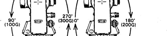
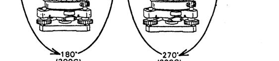
18 6. ANGLE MEASUREMENT 6.1 Observation from Normal/Reversed Position Normal position telescope means that the shaft disc is on the left side of the telescope when observers face eyepiece lens (see figure). Reversed position telescope means that the shaft disc is on the right side of the telescope when observers face eyepiece lens. In angle measuring, we should get the measuring result through averaging the two values got from both observations above. And only in this way can the influence caused by the instrument s systematic errors be eliminated effectively. Therefore, when doing horizontal and vertical observation, rotate telescope 180 to do normal position observation after finishing reversed position observation Reversed Position Observation Normal Position Observation 6.2 Horizontal Angle 0 Setting (0 SET) Sight reticle of the telescope at object A, press 0 SET twice to set the horizontal angle as For instance, sight at object A displaying HR press 0 SET twice displaying HR [OSET] key is valid only for horizontal angle. Horizontal angle can be set to 0 any time except when HOLD key is set. If 0 SET is pressed by mistake during operation, there is no effect unless the key is pressed again. When the beep stops, the instrument is ready for next operation. 6.3 Horizontal and Vertical Angle Measurement (1) Set horizontal angle dextrorotation and vertical angle as zero Turn the instrument clockwise to sight at the object A exactly, press 0 SET twice to set horizontal angle to as the initial zero direction. The steps and displaying contents are as follows: V HR 右 Press twice 0 SET V Vertical angle (zenith distance) in A direction HR Horizontal angle is set to zero in A direction Turn the instrument clockwise and sight at object B, Suppose that: 14
19 V HR 右 Vertical angle (zenith distance) in A direction Dextrotation horizontal angle in AB direction (2) Press R/L to change horizontal angle from right to left mode. Turn the instrument counterclockwise (HL), sight at the object A exactly, press 0 SET twice to set horizontal angle to as the initial zero direction. The steps san displayed results are the same as (1). Turn the instrument counterclockwise and sight at objects B. The displayed contents are the followings: V R Vertical.angle (zenith dis.) in B direction HR 右 Horizontal.angle left in AB direction. 6.4 Lock and Unlock Horizontal Angle (HOLD) During horizontal angle observation, if you want to retain the measured value, press [HOLD] twice. Once horizontal angle is locked, HRL is displayed and the horizontal angle value will not change even if you rotate the instrument. When you sight at the needed direction, press [HOLD] again to release lock function. Then the horizontal angle value is the original locked value. HOLD is invalid for vertical angle or distance. If HOLD key is pressed by mistake during operation, it does not matter unless the key is pressed again. When the beep stops, next operation can be continued. 6.5 Quadrant Sound of Horizontal Angle Setting (1) Sight at the first objective and then press 0 SET twice to set the horizontal angle to zero. (2) Turn the instrument around the vertical axis about 90º until the beep starts,displaying HR (3) Lock the instrument by the clamp screw and set the horizontal angle to by the tangent screw. Then, fix the quadrant target direction by the telescope reticle. (4) determine the quadrant target direction of 180 and 270 using the same method. The beep beeps when the reading passes any of 0,90,180,270. It beeps in the range of ±1 -- ±20. The beep can be canceled in the initial setting. 6.6 Vertical Angle 0 Setting Before starting operation, initial setting in vertical angle is doing according to operation s requirement selecting zenith 0/horizontal 0(Refer to 4.2 initial setting.).vertical disk structures of two settings: 15
20 16
 Zenith distance =(L+360 -R)/2 Index difference =(L+R-360 )/2 (2)Vertical angle: If vertical angle is 0 in horizontal direction, then the vertical angle measured in this way is")
21 6.7 Measure Zenith Distance and Vertical Angle (1)Zenith distance: If vertical angle is 0 in zenith direction, then the vertical angle measured in this way is the zenith distance. (shown as the figure) Zenith distance =(L+360 -R)/2 Index difference =(L+R-360 )/2 (2)Vertical angle: If vertical angle is 0 in horizontal direction, then the vertical angle measured in this way is the perpendicular angle.(see the figure). Vertical angle =(L±180 -R)/2 Index difference=(l+r-180/360)/ If the absolute value of index difference is larger than 10 ( i.e. I 10 ), adjustment should be made as introduced in chapter 8.5 and 8.6 in this manual. 6.8 Slope Percentage The vertical angle can be converted into slope percentage in angle measurement mode. Press V/% and the display shows vertical angle or grade percentage alternately. Slope %=H/Dx100% The range of slope percentage should be between the horizon direction and ±45 (±50G). Otherwise the instrument will display over EEE.EEE% 17
22 6.9 Repeat Angle Measure Turn on the instrument in angle measure mode Operation 错误! 未找到引用源 PressFUNCkey. Display 错误! 未找到引用源 PressRPTkey to enter repeat measure mode. 错误! 未找到引用源 Sight at the first target A. 错误! 未找到引用源 PressL/Rkey to set the reading of the first target as 错误! 未找到引用源 Sight at the second target B with horizontal tangent screw and clamp screw. 错误! 未找到引用源 PressHOLDkey to hold and save it into the instrument. 错误! 未找到引用源 Sight at the target A again with horizontal tangent screw and clamp screw. 错误! 未找到引用源 PressL/Rkey to set the 18
23 first target as 错误! 未找到引用源 Sight at the second target B again with horizontal tangent screw and clamp screw. 错误! 未找到引用源 PressHOLDkey to hold and save it into the instrument. Average angle appears. Repeat steps 错误! 未找到引用源 to 错误! 未找到引用源 to do measure with the number you want to. Press FUNC to exit after completion. The number of repeat measure in repeat measure mode is limited to 8. If exceeds 8 times, it will quit automatically. Sight at the target and begin with step 错误! 未找到引用源 when doing repeat measure again. Press FUNC key to quit repeat measure mode and return to angle measure mode Export Angle Turn on and enter angle measure mode, and press FUNC key to enter the second function selection mode. Press OUT key to export the current angle to serial-port or electronic controller (baud rate is 1200), will be displayed on the screen for one second after successful export Save Angle Turn on and enter angle measure mode, press FUNC key to enter the second function selection mode, and than press REC to save angle. At that time, the current angle is glittering twice, which represents it has been saved to the memory. If you want to save angle again, press REC key after regulating an angle. If you want to look over saved angle data, please refer to Chapter 7 about memory. Notice: the instrument only supplies 256 groups of angle data (each group of angle data includes one vertical angle and one horizontal angle). If angle data saved exceeds256 groups, FULL will be 19
24 displayed on the interface which prompts users that memory is full. Users then need to clear manually to resave angle, please refer to the chapter about memory for more details Measure Distance with Stadia The distance from the measuring object to the instrument can be obtained by using the stadia hair of the telescope with the accuracy 0.4%D. (1) Set up the instrument at point A and put the surveying rod on target point B. (2) Read the intercept d of apparent lines from up and down from the reticle on the survey rod. (3) The horizontal distance(d) between A and B can be attained with the formula below: D= 100 d Left and Right Stadia hair Up and down Stadia hair The precision of this kind of distance measurement is not very high. This method is not used when high precision is required. 20
25 7. MEMORY 7.1 Examine Instrument s Serial Number Operation 错误! 未找到引用源 Press FUNC key and POWER key to turn on. After beeping three times, it enters memory examining interface. What displayed on the main interface is instrument s serial number that is the same as the number printed on the instrument s body, for instance, T53056, shown as the right picture. Hope users check it carefully to protect their own interests. 错误! 未找到引用源 Press FUNC to quit. Display 7.2 Examine Angle Data in Memory Operation Display 错误! 未找到引用源 Press FUNC key and POWER key to turn on. After beeping three times, it enters memory examining interface. 错误! 未找到引用源 PressV/% key to display angle data in memory mode. N. 000 means there is no angle data in memory. 错误! 未找到引用源 N. 001means there are angle data in memory, so we can use and to select angle in memory to look over. Use or to select vertical angle and horizontal angle displayed in the second line. What shown in the right picture is the 4 th group of vertical angle data in memory. 错误! 未找到引用源 press FUNC to quit and return to examining instrument s serial number. PressFUNC again to quit memory mode and return to angle measure mode. 21
26 7.3 Clear Angle Data in Memory In the light of steps of examining angle data in memory, press in examining angle interface for over 5 seconds, it beeps three times, and CLEAR appears on the interface, which represents all angle data in memory are cleared. (Note: memory can save at most 256 groups of data and system will prompt you when storage is full. Then users should transmit useful angle through serial-port and clear data in memory by hand. 7.4 Transmit Data in Memory to Serial-port In the light of steps of examining angle data in memory, press or each time to examine angle data in memory which is transmitted through serial-port at the same time. ( suddenly appears in the second line denotes the current angle has been transmitted through serial-port, which can be examined by serial-port facility such as Serial-port Genius. Baud rate is 9600.) In addition, the function to transmit all angle data to serial-port at a time is furnished. In the light of steps of examining angle data in memory, press in examining angle interface for over 5 seconds, it beeps three times which means it starts to send all angle data to serial-port. Baud rate is 9600 and sending time depends on the number of angle in memory. Note: The format of single angle in memory sent to serial-port is current angle +0x0D+0x0A. The format of all angles in memory sent to serial-port is vertical angle+0x0d+0x0a+ horizontal angle +0x0D+0x0A. Angle is sent to serial-port according to chronological sequence, that is, first in first out. 22
27 8. CONNECTION WITH CONTROLLER Connection electronic theodolite with electronic controller There is a data export and import port that locates at the lower side of optical plummet of STT SERIES electronic theodolite. Transmit measured data to electronic controller for record through connection to electronic controller with cable. 23
28 9. INSPECTION AND ADJUSTMENT 9.1 Plate Vial Inspection See Chapter 5.1 about Leveling with Plate Vial. Adjustment (1) If the bubble of the plate vial drifts away from the center, bring it half excursion back to the center by adjusting the two leveling hand wheels which are parallel to the plate vial. (2) Correcting the remaining half by turning the bubble adjusting screw with the adjusting pin. (3) Confirm that the bubble does not move away from the center when the instrument is rotated to 180 If not, repeat the steps above. (4) Turn the instrument by around 90 and adjust the third screw to center the bubble in the vial. Repeat inspection and adjustment steps until the bubble remains in center in any directions. 9.2 Circular Vial Inspection It is not necessary to adjust if the bubble of the circular vial is in the center after inspecting and adjusting of the plate vial. Adjustment If the bubble of the circular vial is not in the center, bring the bubble to the center by turning adjusting screw with correction pin or adjustable wrench. When adjusting, first loosen the screw on the opposite of the offset direction (1 or 2), then, tighten the adjusting screw in the offset direction to bring the bubble to the center. When the bubble stays in the center, keep the fastening strength of the three screws in uniformity. 9.3 Inclination of Reticle Inspection (1) Level the instrument and select a target A in the line of sight of telescope, sight at A through the center of reticle of graduation board and lock the horizontal and vertical clamp screws. (2) Move point A to the edge (point A ) of the field of view by rotating the vertical tangent screw. (3) No adjustment is necessary if point A moves along the vertical line of the reticle. If point A deviates the vertical line of the reticle, that is reticle is tilted, so we need to do correction on graduation board. Adjustment 24
29 (1) Firstly, remove the eyepiece cover between eyepiece and focusing screw and you can see four screws. (2) Loosen the four reticle adjusting screws equably with a screwdriver. Rotate the reticle around the aiming axis, and align the vertical line of the reticle with point A. (3) Rotate the fastened screw equably. Repeat the inspection and adjustment to see to it that the adjustment is correct. (4) Remount the eyepiece cover. 9.4 Perpendicularity of Aiming Axis and Horizontal Axis (2C) Inspection (1) Set an object A at a far distance, the same height as the instrument, level and center the instrument and turn on the power. (2) Sight at the object A in normal position and read the horizontal angle value. (Suppose that: L= ). (3) Loosen vertical and horizontal clamp screws, and reverse the telescope. Sight at the object A in reversed position and read the horizontal angle value. (Suppose that : R= ) (4) 2C= L-(R±180 ) = 10º13'10''-(190º13'40"-180º) =30 30" 20. That means adjustment is needed. Adjustment (1) To eliminate the big error, use the horizontal tangent screw to adjust the horizontal reading to the correct one: R+C= = (2) Take off the cover of the reticle between eyepiece and focusing screw. Adjust the two adjusting screws by loosening one and tightening the other. Move the reticle to sight at the object A exactly. (3) Repeat inspection and adjustment until 2C <20. (4) Remount the cover of reticle back. Reticle adjustment screws(four) Reticle fixing screws(four) 9.5 Automatic Compensation for Vertical Index Difference Inspection Liquid condenser automatic compensation set is used for vertical index zeroing compensation. We can check if the function works well by the following method. (1) Mount and level the instrument and make the telescope parallel with the line connecting the center of the instrument to any one of the screws. Then, lock the horizontal clamp screw. (2) Zero the vertical index after turning on the power. Lock the vertical clamp screw and the instrument displays the vertical angle value. (3) Rotate the above screw in a direction slowly to about 10mm circumference. The displayed value will change correspondingly and then disappear and display the message b. The vertical axis inclines more than 3 at this time and exceeds the designed compensation range. When you rotate the above screw reversely to the original position, the instrument displays the vertical angle again which means that the vertical index difference compensation function works well. (Experiment repeatedly and observe its change at critical position.) 25
30 Adjustment If the compensation does not work well, send the instrument back to factory for repairment. 05B model instrument does not have vertical zero automatic compensation set. 9.6 Vertical Index Difference (I Angle) and Set Vertical Index Zero After making adjustments as described in 8-3 and 8-5, make the inspection as follows: Inspection (1) Set up the instrument and turn on. Sight at a reference A and obtain the vertical angle (Left). (2) Reverse the telescope and sight at the object A again and obtain the vertical angle (Right). (3) If vertical angle is zero at zenith, then, I=(L+R-360 )/2; If vertical angle is zero at horizon, then, I=(L+R-180 )/2 or (L+R-540 )/2. (4) If i 10, vertical index zeroing should be set again. Adjustment (Setting up vertical index zeroing) (1) After leveling the instrument, press0 SET to turn on and hold it until three beeps. The instrument displays that: V C SET -- 1 (2) In normal position, turn the telescope around near the horizontal direction until vertical angle appears. Sight at a clear and stable objective A, which is nearly the same height as the instrument. PressO SET key, displaying: V C SET -- 2 (3) Reverse the telescope and sight at the object A again. Press0 SET key to finish vertical index zeroing setting. The instrument returns to angle measurement mode. (4) Repeat the inspection procedures. If I 10, check if anything is wrong in operation and repeat the adjustment again. (5) If the vertical index difference does not meet the standard yet after being adjusted repeatedly, the instrument should be sent to factory to be repaired. The vertical angle displayed in the process of zeroing setting is not compensated and corrected, so it can not be used formally but as a reference value. 9.7 Optical Plummet Inspection (1) Set the instrument on the tripod, and place a piece of white paper with a cross on the ground right under the instrument. (2) Adjust the optical plummet focus, and move the center of the crosshairs drawn on the paper to the center of the field of view. (3) Adjust the leveling screws to make the center mark of the optical plummet coincide with the intersecting point of the reticle. (4) Rotate the instrument around the vertical axis at every 90 and observe that whether the center mark position coincides with the intersecting point of the reticle. 26
31 (5) If the center mark always coincides with intersecting point when rotating the instrument, no adjustment is necessary. Otherwise, the following adjustment is needed. Adjustment (1) Take off the protecting cover between the optical plummet eyepiece and focusing knob. (2) On the white paper with a crosshairs, mark the place of the center mark when the instrument moves at every 90, and mark them A,B,C,D respectively. (3) Join the diagonals with lines (A, C and B, D).The intersecting point of the two lines is called 0. (4) Adjust the four correction screws of the optical plummet by an adjusting pin until the center mark coincides with the smaller circle o. (5) Repeat the above inspecting and adjusting steps until it is up to the requirement. (6) Remount the protecting cover. 9.8 Other Adjustment If the leveling screw looses, adjust it with two correction screws on the basal plate. Tighten the screws till they are fit. 27
32 10. SPECIFICATIONS Telescope Image Erect Magnification 30X Effective aperture 45mm Resolution 3 Field of view 1 30 Shortest stadia 1.4m Stadia multiplication constant 100 Stadia additive constant 0 Stadia precision 0.40%L Tube length 157mm Angle measurement Angle measurement mode Absolute encoding mode Diameter of raster disks (vertical and horizontal) 79mm Minimum display reading 1 or 5,optional Detection mode Horizontal angle: dual Vertical angle : dual Angle measurement Unit 360 / 400gon/6400mil,optional Precision STT SERIES 2 : 2, STT SERIES 5: 5 Leveling vials Plate vial 30 /2mm Circular vial 8 /2mm Vertical compensator(05b mode without this item) System liquid condenser mode, optional Working range ±3 Precision ±3 Optical plummet Image Erect image Magnification 3X Focusing range 0.5~ Field of view 5 Display Type LCD, double lines, line segment Data input/output Interface RS --232C On-board battery Power source Rechargeable NI-H Battery Voltage DC 4.8V Continuous working hours 8h Working environment Working Temperature Dimensions and weight Overall dimensions Instrument weight -20 ~ X150X330mm 5.2kg 28
33 11. COMMON MISTAKE When operating the instrument improperly or circuit within the equipment has problems, error codes will be displayed on the screen, whose contents and solving methods are listed as follows: Error Code Err 01 Err 02 Err 03 Err 04 Err 05 Err 06 Err 07 Err 08 Err 20 Err 21 Meaning and Solution Something wrong with horizontal disk measurement Turn off the instrument,then power on,if Err01still appears, send it to be repaired. Telescope is rotated too fast.pressv/%,after displaying V 0SET,show vertical disk index Retune to 0 (namely rotate telescope up and down near the horizontal position when left disk). Collimator is rotated too fasr.press0 SET to reset. Something wrong with vertical photo-electric convertor (Ⅰ). Send it to be repaired. Something wrong with horizontal photo-electric convertor (Ⅰ). Send it to be repaired. Something wrong with horizontal photo-electric convertor (Ⅱ). Send it to be repaired. Something wrong with vertical photo-electric convertor (Ⅱ). Send it to be repaired. Something wrong with vertical disk. Turn off and level the instrument. If Err 08 still appears after power on, send it to be repaired. Something wrong with 0set of vertical disk index. Operate again according to chapter 8.6. If Err 20 still appears, press HOLD O SET HOLD to force setting. Exceeded zero-point of electronic compensator of vertical angle. Turn off and level the instrument. If Err 21 still appears after power on, send it to be repaired. When errors appear, check the instrument and your operation steps. If you confirm that something is wrong with the instrument, send it to factory to be repaired. 29
34 12. ACCESSORIES Standard Configuration Packing Case 1 Mainframe(including a battery) 1 Charger 1 AA Battery Box 1 Plumb 1 Correction Pin 2 Soft Brush 1 Screwdriver 1 Inner Hexad Wrench 2 Floss Cloth 1 Dryer 1 Certificate of approval 1 Operation Manual 1 Optional Configuration Boluo Board 1 Syphon Eyepiece 1 Sunglass 1 STONEX LIMITED Corporate office 5th floor,86 Jermyn Street London SW1Y 6AW United Kingdom Ph Fax Registered in England under no Website info@stonexsurveying.com 30
Welcome to purchase and use our products and thank you for your confidence in our company s products!
 PREFACE Dear users: Welcome to purchase and use our products and thank you for your confidence in our company s products! It has been our target to innovate the international-level advanced surveying instrument
GT-510/510L series Instruction Manual
 GT-510/510L series Instruction Manual NO.3.20110322 Contents 1 INSTRUMENT FEATURES... - 1 2 QUICK GUIDE... - 2 2.1 INSTRUMENT PACKING...- 2 2.2 NAME OF INSTRUMENT PARTS...- 3 2.3 UNPACK AND STORAGE...-
Fig. 1. instrument is in the case
 1. Applications The NETH503 series Electronic Theodolite has an optical incremental grading system which features digital angle measurements. It can achieve measurement, calculating, display and memory
DWT-10 Instruction Manual
 DWT-10 Instruction Manual For Customer Service Call (781) 848-7702 or Fax (781) 848-8022 Congratulations on your choice of this David White Electronic Digital Transit. We suggest that you read this instruction
INTRODUCTION TO ENGINEERING SURVEYING (CE 1305)
") INTRODUCTION TO ENGINEERING SURVEYING (CE 1305) Linear Measurements Sr Dr. Tan Liat Choon Email: tanliatchoon@gmail.com Mobile: 016-4975551 1 EDM, TOTAL STATION, PRISM AND POLE 2 ELECTROMAGNETIC DISTANCE
INTRODUCTION TO ENGINEERING SURVEYING (CE 1305) Linear Measurements Sr Dr. Tan Liat Choon Email: tanliatchoon@gmail.com Mobile: 016-4975551 1 EDM, TOTAL STATION, PRISM AND POLE 2 ELECTROMAGNETIC DISTANCE
22X Builder s Level Model No Instruction Manual
 2594H 7/29/09 10:12 AM Page 1 22X Builder s Level Model No. 40-6900 Instruction Manual Congratulations on your choice of this 22X Builder s Level. We suggest you read this instruction manual thoroughly
22X Builder s Transit Level Model No Instruction Manual
 2595H 7/29/09 10:15 AM Page 1 22X Builder s Transit Level Model No. 40-6910 Instruction Manual Congratulations on your choice of this 22X Builder s Transit Level. We suggest you read this instruction manual
Owner's Manual NSL100B BUILDERS LEVEL NSL500B TRANSIT LEVEL
 Owner's Manual NSL100B BUILDERS LEVEL NSL500B TRANSIT LEVEL 1 1. CONTENTS 2. Nomenclature page 3 3. Care and Maintenance page 4 4. Using your Instrument 4.1 Setting up your Instrument page 5 4.2 Stadia
Automatic Level NP-732
 INSTRUCTIONS FOR USE Automatic Level NP-732 Contents Before use 2 1.Nomenclature. 3 2.Operation....4 2-1 Preparing before surveying...4 2-2 Surveying method..........5 2-2-1 Measuring altitude difference...5
Owner's Manual. for AUTOMATIC LEVEL. NBL Series. FOR CUSTOMER SERVICE, PARTS & REPAIR, CALL Toll Free:
 Owner's Manual for AUTOMATIC LEVEL NBL Series FOR CUSTOMER SERVICE, PARTS & REPAIR, CALL Toll Free: 1-888-247-1960 1 1. CONTENTS 2. Nomenclature page 3 3. Care and Maintenance page 4 4. Using your Instrument
model SKT05 SKT05L Toll Free: (855) IMPORTANT: Read Before Using IMPORTANT Lire avant usage IMPORTANTE: Leer antes de usar
 IMPORTANT: Read Before Using IMPORTANT Lire avant usage IMPORTANTE: Leer antes de usar") Operating / Safety Instructions Consignes de fonctionnement / sécurité Instrucciones de funcionamiento y seguridad IMPORTANT: Read Before Using IMPORTANT Lire avant usage IMPORTANTE: Leer antes de usar
Operating / Safety Instructions Consignes de fonctionnement / sécurité Instrucciones de funcionamiento y seguridad IMPORTANT: Read Before Using IMPORTANT Lire avant usage IMPORTANTE: Leer antes de usar
取扱説明書 /INSTRUCTION MANUAL 自動レベル /AUTOMATIC LEVEL AT-B2/B3/B4 FC10386-A012-02
 取扱説明書 /INSTRUCTION MANUAL 自動レベル /AUTOMATIC LEVEL AT-B2/B3/B4 FC10386-A012-02 SURVEYING INSTRUMENTS INSTRUCTION MANUAL AUTOMATIC LEVEL AT-B2/B3/B4 Thank you for selecting the AT-B2/B3/B4. Please read this
EE 1/3.5х14 U EE 1/3.5х14 U
 EE 1/3.5х14 U EE 1/3.5х14 U EE 1/3.5х14 U Table of contents 14 Item No. 1. 2. 3. 4. 5. 6. 7. 8. 9. Section Description of sight Purpose Specification Complete set Design and Principle of Operation Rules
Automatic Level Maintenance Manual SAL-XX W/ AIR DAMPENED COMPENSATOR
 Automatic Level Maintenance Manual SAL-XX W/ AIR DAMPENED COMPENSATOR CST/Berger 2001 SAL 20/24/28/32 PAGE 1 REV. C 071803 Automatic Level Maintenance Manual User Calibration and Testing... 3 Circular
FOCUS 30/FOCUS 35 Field Calibration with Survey Pro Field Software
 GeoInstruments Application Note June 25th, 2015 FOCUS 30/FOCUS 35 Field Calibration with Survey Pro Field Software Summary: This support note outlines the procedure which should be followed to calibrate
x Builders Level Service Manual
 40-690 22x Builders Level Service Manual Item Description Pages.0 Overall Instrument Assembly 2. Main Assembly 2.2 Telescope Assembly 3.3 Base Assembly 4.4 Frame Assembly 5 2.0 Calibration 6-8 2. Vial
WATTS MICROPTIC ALIDADE OPERATING INSTRUCTIONS 20-7
 WATTS MICROPTIC ALIDADE 20-7 OPERATING INSTRUCTIONS WATTS Operating Instructions for the WATTS MICROPTIC ALIDADE SA100 SA101 RANK PRECISION INDUSTRIES METROLOGY DIVISION Survey Equipment Sales Langston
National Optical & Scientific Instrument Inc Tri-County Parkway Schertz, Texas Phone (210) Fax (210)
 Fax (210)") National Optical & Scientific Instrument Inc. 6508 Tri-County Parkway Schertz, Texas 78154 Phone (210) 590-9010 Fax (210) 590-1104 INSTRUCTIONS FOR SHOP MICROSCOPES MODEL NUMBERS 186 187 188 189 National
National Optical & Scientific Instrument Inc. 6508 Tri-County Parkway Schertz, Texas 78154 Phone (210) 590-9010 Fax (210) 590-1104 INSTRUCTIONS FOR SHOP MICROSCOPES MODEL NUMBERS 186 187 188 189 National
LEAPERS, INC. RED/GREEN DOTS
 LEAPERS, INC. 1 RED/GREEN DOTS range estimating scopes UTG reticle intensified scopes TOTAL SOLUTION TO YOUR NEEDS -COMMITMENT TO BEST QUALITY, BEST VALUE AND BEST SERVICEwww.LEAPERS.com 32700 Capitol
SURVEYING INSTRUMENTS DT7C DT20C. Electronic Digital Theodolite OPERATOR'S MANUAL
 SURVEYING INSTRUMENTS DT7C DT20C Electronic Digital Theodolite OPERATOR'S MANUAL This is the mark of the Japan Surveying Instruments Manufacturers Association. SURVEYING INSTRUMENTS DT7C DT20C Electronic
Digital Land Surveying And Mapping(DLS&M) Dr. Jayanta Kumar Ghosh Department of Civil Engineering Indian Institute of Technology, Roorkee
 Dr. Jayanta Kumar Ghosh Department of Civil Engineering Indian Institute of Technology, Roorkee") Digital Land Surveying And Mapping(DLS&M) Dr. Jayanta Kumar Ghosh Department of Civil Engineering Indian Institute of Technology, Roorkee Lecture - 17 Total Station Introduction Welcome students, this
Digital Land Surveying And Mapping(DLS&M) Dr. Jayanta Kumar Ghosh Department of Civil Engineering Indian Institute of Technology, Roorkee Lecture - 17 Total Station Introduction Welcome students, this
CIV : THEODOLITE ADJUSTMENT
 Unit CIV2202: Surveying 10.1 CIV2202.10: THEODOLITE ADJUSTMENT Table of Contents PREVIEW...2 Introduction...2 Objectives...2 Readings...2 REGULAR CHECKS...2 Tripod...2 Footscrews...2 Tribrach head...3
~.LIETZ ~. LI ETZ INSTRUCTION MANUAL DOUBLE CENTER THEODOLITE TM-20C THE LIETZ COMPANY E. Del Arno Blvd. Carson, Ca (213)
") ~.LIETZ DOUBLE CENTER THEODOLITE TM-20C INSTRUCTION MANUAL f~, ~. LI ETZ THE LIETZ COMPANY 1645 E. Del Arno Blvd. Carson, Ca. 90746. (213)537-0410 n INSTRUMENT NOMENCLATURE cr, il (~ iíl i) Ii: in CD CD
~.LIETZ DOUBLE CENTER THEODOLITE TM-20C INSTRUCTION MANUAL f~, ~. LI ETZ THE LIETZ COMPANY 1645 E. Del Arno Blvd. Carson, Ca. 90746. (213)537-0410 n INSTRUMENT NOMENCLATURE cr, il (~ iíl i) Ii: in CD CD
Assembly Manual for the Brevard Astronomical Society 16 inch F4.5 Dobsonian Telescope Brevard Astronomical Society P.O. Box 1084 Cocoa, FL 32922
 BAS 16 Telescope Manual Rev 1 Assembly Manual for the Brevard Astronomical Society 16 inch F4.5 Dobsonian Telescope Brevard Astronomical Society P.O. Box 1084 Cocoa, FL 32922 TABLE OF CONTENTS SECTION
DIGITAL ABBE REFRACTOMETER INE-WYA-2S OPERATING INSTRUCTION PLEASE READ THIS MANUAL CAREFULLY BEFORE OPERATION
 DIGITAL ABBE REFRACTOMETER INE-WYA-2S OPERATING INSTRUCTION PLEASE READ THIS MANUAL CAREFULLY BEFORE OPERATION 3, Hagavish st. Israel 58817 Tel: 972 3 5595252, Fax: 972 3 5594529 mrc@mrclab.com MRC.11.16
NcSTAR SHOOTER II SERIES SCOPE
 NcSTAR SHOOTER II SERIES SCOPE Congratulations on the purchase of your New NcSTAR Shooter II Series Scope! The Shooter II Series of scopes gives you many great options, so you can choose the scope that
Richter Optica. Instructions for Model: S850 Stereo Zoom Microscope
 Richter Optica info@richter-optica.com Instructions for Model: S850 Stereo Zoom Microscope Microscope Head Focus Knob Stage Clips Zoom Knob C-Mount Adapter Eyepiece Focusing Holder Focusing Holder Set
H050 E 97.1.DF.2. Automatic Levels AS-2 / AS-2C
 H050 E 97.1.DF.2 Automatic Levels AS-2 / AS-2C ikoninstruction Manual Thank you for purchasing the Nikon automatic levels AS-2/AS-2C. The AS-2/AS-2C is designed for high precision surveys in civil engineering
Quick Start Guide. The ieq45 GoTo German Equatorial Mount # 8000C
 Quick Start Guide The ieq45 GoTo German Equatorial Mount # 8000C PACKAGE CONTENTS Telescope Mount (with built-in GPS) 3.5 Vixen type dovetail saddle (installed on the mount) 8 Losmandy-D type dovetail
R-300 SERIES R-315(N)/R-325(N)/R-335(N) R-322(N)/R-323(N)/R-326. Electronic Total Station. Instruction Manual
/R-325(N)/R-335(N) R-322(N)/R-323(N)/R-326. Electronic Total Station. Instruction Manual") PENTAX R-300 (p01-19) 10/30/02 11:20 AM Page c R Instruction Manual Electronic Total Station R-300 SERIES R-315(N)/R-325(N)/R-335(N) R-322(N)/R-323(N)/R-326 PENTAX R-300 (p01-19) 10/30/02 11:20 AM Page
PENTAX R-300 (p01-19) 10/30/02 11:20 AM Page c R Instruction Manual Electronic Total Station R-300 SERIES R-315(N)/R-325(N)/R-335(N) R-322(N)/R-323(N)/R-326 PENTAX R-300 (p01-19) 10/30/02 11:20 AM Page
Cleveland State University
 CVE 212 - Surveying Lab #1 MEASURING ANGLES & DISTANCES WITH A TOTAL STATION EQUIPMENT EDMI and Tripod Single prism mounted on a prism pole Field book Pencil 2 Walkie Talkies INTRODUCTION Recent developments
Directions for use
 Directions for use 40070 40080 60050 70060 70076 80060 90060 900114 Fig. 1 Fig. 1A Fig. 2 Fig. 3 Fig. 4 Fig. 5 Fig. 6 Fig. 7 english ENGLISH DIRECTIONS FOR USE 1 Tripod Leg 2 Tripod Leg Adjusting Screw
Carlson CR Robotic/Reflectorless Total Station
 0 West Second Street Suite 00 Maysville, KY 4056 www.carlsonsw.com Phone: 606-564-508 Fax: 606-564-64 Type starts around here Carlson CR Robotic/Reflectorless Total Station Calibration Overview Congratulations
Instruction Manual. Model #: (Reflector) Lit #: / 06-07
 Lit #: / 06-07") Instruction Manual Model #: 49114500 (Reflector) Model #: 49060700 () Model #: 49070800 () Lit #: 93-0468 / 06-07 PARTS DIAGRAM C E D B A F G H I J NOTE: Actual product may have improvements that are not
Instruction Manual Model #: 49114500 (Reflector) Model #: 49060700 () Model #: 49070800 () Lit #: 93-0468 / 06-07 PARTS DIAGRAM C E D B A F G H I J NOTE: Actual product may have improvements that are not
HS515G-M. PARALOW Circle Dot Sight. User's Manual. Holosun Technologies Inc. Phone: (909) Fax: (909)
 Fax: (909)") HS515G-M PARALOW Circle Dot Sight User's Manual Multi Reticle Holosun Technologies Inc. Phone: (909) 594-2888 Fax: (909) 598-4888 E-mail: info@holosun.com COLOR www.holosun.com PARALOW HS515G-M PARALOW
HS515G-M PARALOW Circle Dot Sight User's Manual Multi Reticle Holosun Technologies Inc. Phone: (909) 594-2888 Fax: (909) 598-4888 E-mail: info@holosun.com COLOR www.holosun.com PARALOW HS515G-M PARALOW
C A S S I N I TRACKER
 C A S S I N I TRACKER ASTRONOMICAL REFLECTOR T ELESCOPE SERIES #C-80080TR #C-1100102TR #C-1000120TR #C-1000120TREF #C-900135TR COSMO BRANDS INC. WWW.COSMOSOPTICS.COM 2 CASSINI REFLECTING TELESCOPE OPERATING
saxon Instruction Manual saxon Grandeur Brass Telescope High quality optics
 saxon High quality optics Instruction Manual saxon Grandeur Brass Telescope WARNING! Do not use the telescope to look at the sun without an appropriate solar filter. Looking at or near the sun can result
AccuAligning TM Polar Scope for SmartEQ TM Portable German Equatorial GOTO Mount. Installation and User Manual. Product #3130
 AccuAligning TM Polar Scope for SmartEQ TM Portable German Equatorial GOTO Mount Installation and User Manual Product #3130 ioptron Corporation, 6E Gill Street, Woburn, MA 01801 www.ioptron.com ioptron
DHS1900 DHS3000 High Temperature Hand Held Infrareds User Manual
 DHS1900 DHS3000 High Temperature Hand Held Infrareds User Manual WD1063 Rev B Revised 02/23/15 Wahl Instruments Inc. 234 Old Weaverville Road Asheville, NC 28804 Toll Free: 800-421-2853 Phone: 828-658-3131
5-25x56 PMII PSR With Double Turn
 Page 1 of 20 5-25x56 PMII PSR 5-25x56 PMII PSR With Double Turn Page 3 of 20 1. Scope description... 5 1.1 Introduction... 5 1.2 Safety instructions... 5 2. Technical data... 6 2.1 General data... 6 2.2
LT8-300LTU Owner s Guide
 LT8-300LTU Owner s Guide LT8-300LTU LT8-300LTULP FOR CUSTOMER SERVICE, PARTS AND REPAIR CALL (765) 581-4097 www.davidwhite.us.com IMPORTANT: IMPORTANT : IMPORTANTE: Read Before Using Lire avant usage Leer
Dual Red or Green Electronic Dot Sight Instruction Manual
 Dual Red or Green Electronic Dot Sight Instruction Manual 2007 VisionPlus INTRODUCTION: Congratulations on your purchase of a VisionPlus Dual Red/Green Electronic Dot Sight. This is a quality product engineered
Operating Manual 1.1-4x24 Zenith x24 Zenith
 Page 1 of 16 Page 3 of 16 1. Scope description... 4 1.1 Introduction... 4 1.2 Safety instructions... 4 2. Technical data... 5 2.1 General data... 5 2.2 Dimensions... 5 3. Accessories / Scope of supply...
5-25x56 PMII PSR Illuminated with Double Turn
 Page 1 of 20 5-25x56 PMII PSR Illuminated with Double Turn Page 3 of 20 1. Scope description... 5 1.1 Introduction... 5 1.2 Safety instructions... 5 2. Technical data... 6 2.1 General data... 6 2.2 Dimensions...
CASSINI CQR-800 OPERATING INSTRUCTIONS INTRODUCTION
 HQR-800 CASSINI CQR-800 OPERATING INSTRUCTIONS INTRODUCTION CONGRATULATIONS ON YOUR PURCHASE OF THE CASSINI CQR-800 TELESCOPE. THIS TELESCOPE HAS BEEN PRODUCED TO PRECISE SPECIFICATIONS. PRIOR TO USING
Kalinka Optics Warehouse User Manual Kobra AK Side Mount Red Dot Sight Manual
 Kalinka Optics Warehouse User Manual www.kalinkaoptics.com Kobra AK Side Mount Red Dot Sight Manual CONTENTS 1. Introduction... 4 2. Purpose... 4 3. Specifications... 4 4. Components and Equipment Provided...
SCHIEBER TELESCOPES. Unique, High-Quality Telescopes
 SCHIEBER TELESCOPES Unique, High-Quality Telescopes 3.5 Refractor Astrophotography Bundle - Strike 90 PLUS Telescope Assembly Instructions and Digital Eyepiece Camera Instructions. (1) telescope assembly
CBRD30CP3 & BOWRD30CP INSTRUCTION MANUAL
 CBRD30CP3 & BOWRD30CP INSTRUCTION MANUAL PROLOGUE Your BSA Illuminated sight is for use on both compound and standard bows. Each version of the BSA illuminated sight has a specific reticle to help maintain
Telescope. 1. Read these instructions carefully and familiarise yourself with the procedure before assembling the unit.
 Telescope a Simple assembly instructions- Please keep for future reference IMPORTANT 1. Read these instructions carefully and familiarise yourself with the procedure before assembling the unit. 2. Check
COMMODORE BRASS TELESCOPE ZHUMELL COMMODORE BRASS TELESCOPE
 3 0 15 15 E OWNER S MANUAL COMMODORE BRASS TELESCOPE ZHUMELL COMMODORE BRASS TELESCOPE 5 W 60 W 30 W 45 W Zhumell customers know that there are plenty of ways to experience the world. They also understand
product manual H-3220A Benkelman Beam
 05.12 product manual H-3220A Benkelman Beam General The H-3220A Benkelman Beam Apparatus is a convenient and accurate device used for measuring the deflection of flexible pavements under moving wheel
Platinum Series. 6-30x56 Front Focal Plane Scope. with Patent Pending DEKA MIL Reticle. DEKA MIL reticle for unsurpassed accuracy at long range
 6-30x56 Front Focal Plane Scope with Patent Pending DEKA MIL Reticle DEKA MIL reticle for unsurpassed accuracy at long range PA6-30X56FFP-DEKA-AMS Platinum Series 1. Turn the Power Ring to a high setting,
Observing Procedure for C11 GPS
 Observing Procedure for C11 GPS By T. W. Fuller Preparation Customize observing list You can install a list of up to 25 custom objects in the telescope database ahead of time, so that you will have them
S5 SERIES Rifl escope Rifl
 S5SERIES Rifl escope Warranty It s all about the experience! At STYRKA, we strive to make sure your experience in the fi eld is a great one. And we stand behind our products to do just that. That s why
Observatory 8 inch Telescopes: Tips, Tools & Quick Fixes
 Observatory 8 inch Telescopes: Tips, Tools & Quick Fixes Rhiannon Griffin August 7, 2014 1 Tools Needed Allen wrenches for set screws, 2 sizes For collimating: Phillips head screwdriver & slotted screwdriver
RT-6 Riflescopes. User Guide
 RT-6 Riflescopes User Guide This user guide includes information for low-magnification RT-6 riflescopes. Please review thoroughly, and pay close attention to the details pertaining to your specific riflescope
Bright Advance Corporation
 USER INSTRUCTIONS TABLE OF CONTENTS INSTRUCTIONS FOR USE2 PREPARING TO USE THE SCALE2 DISPLAYS3 KEYBOARD FUNCTION4 OPERATION7 COUNTING14 DIFFERENT KEYBOARD TYPES21 INTERFACE31 POWER SOURCES40 1 INSTRUCTIONS
2-7x32. Instruction manual
 In the event that you should require service for your Nikon RIFLESCOPE, please send it directly to: Nikon Scope Service 841 Apollo Street, Suite 100 El Segundo, CA. 90245-4721 1-800-Nikon SV. 2-7x32 Manufacturer:
DT220 DT520 DT520S DT520A DT520AS DT620 DT620S
 SURVEYING INSTRUMENTS DT220 DT520 DT520S DT520A DT520AS DT620 DT620S Electronic Digital Theodolite OPERATOR'S MANUAL This is the mark of the Japan Surveying Instruments Manufacturers Association. SURVEYING
RP-200 TELESCOPE Instruction Manual
 2070 5th Avenue Ronkonkoma, NY 11779 Phone: 631-963-5000 Fax: 631-427-6749 For information, call toll-free: 1-800-967-8427 info@carson.com / sales@carson.com / www.carson.com RP-200 TELESCOPE Instruction
THE HAVERFORD UNIVERSITY S STRAWBRIDGE OBSERVATORY S OF THE 16 MEADE. A quick guide to using the 16 Meade Schmidt-Cassegrain Telescope
 THE S OF THE 16 MEADE HAVERFORD UNIVERSITY S STRAWBRIDGE OBSERVATORY A quick guide to using the 16 Meade Schmidt-Cassegrain Telescope First draft: Scott Engle, Fall 2010; Update: Steve Boughn, Fall 2012
ASTRO-PHYSICS, INC. POLAR ALIGNMENT TELESCOPE
 Polar Alignment Telescope ASTRO-PHYSICS, INC. POLAR ALIGNMENT TELESCOPE This polar axis telescope will help you align your mount with the Celestial Poles. When your mount is properly aligned, your telescope's
GY 301: Geomorphology Lab 5: Total Station Mapping Project
 Introduction This is the capstone lab project for GY 301. With the assistance of your team member (4 people per team), you will use the Total Station to survey a topographic map of the campus area (see
RP-100 TELESCOPE Instruction Manual
 2070 5th Avenue Ronkonkoma, NY 11779 Phone: 631-963-5000 Fax: 631-427-6749 For information, call toll-free: 1-800-967-8427 info@carson.com / sales@carson.com / www.carson.com RP-100 TELESCOPE Instruction
C4 PLUS RIFLESCOPES User Guide
 C4 Plus USER GUIDE_Layout 1 7/24/15 2:40 PM Page 1 C4 PLUS RIFLESCOPES User Guide This user guide includes information for the entire C4 Plus riflescope line. Please review thoroughly and pay close attention
ASTRO-PHYSICS, INC. POLAR ALIGNMENT TELESCOPE (PASILL2)
") OBJECTIVE LENS ASTRO-PHYSICS, INC. POLAR ALIGNMENT TELESCOPE (PASILL2) This model shipped from January 2001 through July 2002. It fits all 400, 600, 600E, 800, 900 and 1200 models (except the original
OBJECTIVE LENS ASTRO-PHYSICS, INC. POLAR ALIGNMENT TELESCOPE (PASILL2) This model shipped from January 2001 through July 2002. It fits all 400, 600, 600E, 800, 900 and 1200 models (except the original
total station Instruction manual Basic Procedures
 total station R-200series Instruction manual Basic Procedures for R-200 Series R-202NE R-205NE (Power) TI Asahi Co., Ltd. International Sales Department 4-3-4 Ueno Iwatsuki-Ku, Saitama-Shi Saitama, 339-0073
CASSINI CQR-120 OPERATING INSTRUCTIONS
 CASSINI CQR-120 OPERATING INSTRUCTIONS INTRODUCTION CONGRATULATIONS ON YOUR PURCHASE OF THE CASSINI CQR-120 TELESCOPE. THIS TELESCOPE HAS BEEN PRODUCED TO PRECISE SPECIFICATIONS. PRIOR TO USING YOUR NEW
CONTENT FORWORDS... 1 FEATURES... 5 PRECAUTIONS BRIEF INTRODUCTION... 7
 FORWORDS Congratulations on purchasing Total Station CTS-662 series. This manual will give a detailed and complete instruction about this total station. Please read it carefully before use. 1 CONTENT FORWORDS...
C A S S I N I. MODEL : C EQ3 900mm X 135mm COSMO BRANDS INC.
 C A S S I N I MODEL : C-900135EQ3 900mm X 135mm COSMO BRANDS INC. WWW.COSMOSOPTICS.COM 2 C A S S I N I C-900135EQ3 TELESCOPE OPERATING INSTRUCTIONS INTRODUCTION CONGRATULATIONS ON YOUR PURCHASE OF THE
PLI Support Guide: Robotic Total Station Field Calibration
 PLI Support Guide: Robotic Total Station Field Calibration Summary: This manual will instruct you on how to properly calibrate your Trimble Robotic Total Station using Trimble Access. Your instrument must
Surveying Prof. Bharat Lohani Indian Institute of Technology, Kanpur. Module 5 Lecture 1
 Surveying Prof. Bharat Lohani Indian Institute of Technology, Kanpur (Refer Slide Time: 00:20) Module 5 Lecture 1 Welcome to this another lecture on basic surveying. Today we are going to start a new module.
Instruction Manual. Kite-22 Camera Crane Starter Package (KITE-22-STARTER) Exclusive of Weights
 Exclusive of Weights") Instruction Manual Kite-22 Camera Crane Starter Package (KITE-22-STARTER) Exclusive of Weights All rights reserved No part of this document may be reproduced, stored in a retrieval system, or transmitted
Instruction Manual Kite-22 Camera Crane Starter Package (KITE-22-STARTER) Exclusive of Weights All rights reserved No part of this document may be reproduced, stored in a retrieval system, or transmitted
ZFK 4 X 25. Description and Utilization Instructions
 1. Clarification of Concept The ZFK 4 x 5 is a telescopic sight with fixed magnification with dual cross hair adjustments, central viewing, and attached mount. ZFK 4 X 5 Description and Utilization Instructions.
RECON. How to Setup the Telescope to Observe. This guide will show you how to setup your telescope for observing. Written By: Brittany McCrigler
 RECON How to Setup the Telescope to Observe This guide will show you how to setup your telescope for observing. Written By: Brittany McCrigler 2017 recon.dozuki.com Page 1 of 30 INTRODUCTION This guide
SKELESCOPE REFLECTOR TELESCOPE WITH TABLE TOP TRIPOD SK-100 INSTRUCTION MANUAL
 TM SKELESCOPE REFLECTOR TELESCOPE WITH TABLE TOP TRIPOD SK-100 INSTRUCTION MANUAL TABLE OF CONTENTS Introduction Box Contents / Visual Key Diagram Telescope Assembly Setting up Your Telescope Attaching
10 - Celestron Telescope II: Operation
 10 - Celestron Telescope II: Operation Purpose: Gain more experience setting up a 6 Celestron telescope, familiarize yourself with the software interface, and acquire an image with the CCD camera. Due:
2. OPERATIONAL CONDITIONS
 1. INTRODUCTION This device was designed for modern physics labs of colleges and graduate schools. It demonstrates the influence of a magnetic field on light, known as Zeeman Effect, and reveals the behavior
1 YEAR LIMITED WARRANTY TELESCOPES
 1 YEAR LIMITED WARRANTY TELESCOPES BARSKA Optics, as manufacturer, warrants this new precision optical product to be free of original defects in materials and/or workmanship for the length of time specified
30 mm Diameter Main Tube 1-4x24 Models
 CrossFire MANUAL 30 mm Diameter Main Tube 1-4x24 Models The Crossfire Riflescopes Specifically designed for discriminating hunters and shooters, the Crossfire series of riflescopes offer the highest levels
Altazimuth Mount. Altazimuth Mount
 instruction Manual Orion VersaGo II HD Altazimuth Mount #10104 Orion VersaGo II Altazimuth Mount #10105 #10104 #10105 Providing Exceptional Consumer Optical Products Since 1975 OrionTelescopes.com Customer
R-1502N R-1503N R-1505N INSTRUCTION MANUAL
 TOTAL STATION R-1500SERIES R-1502N R-1503N R-1505N INSTRUCTION MANUAL Basic Procedures Content Exemption clause... 3 PRECAUTIONS REGARDING SAFETY... 4 Usage precautions... 7 1. BASIC OPERATION... 10
Surveying Instruments. B Series B20 B30 B40. Automatic Levels
 Surveying Instruments B Series B20 B30 B40 Automatic Levels World-Proven Precision and Durability B20 Automatic Level B30 Automatic Level B40 Automatic Level 28x 1.5mm Accuracy 32x 0.7mm Accuracy 24x 2.0mm
EPOCSELFIR LACITCATiX5T TECHNICAL MANUAL
 T5Xi TACTICAL RIFLESCOPE TECHNICAL MANUAL TABLE OF CONTENTS Page Mounting The Scope...2 Eyepiece Focusing...2 Windge / Elevation Adjustment...3 Setting The Zero Stop...4 Turret Cap Replacement...4 Parallax
DETERMINATION OF AREA OF POLYGON BY CHAIN AND CROSS STAFF SURVEY 1. AIM:
 Expt. No: 2 Date: DETERMINATION OF AREA OF POLYGON BY CHAIN AND CROSS STAFF SURVEY 1. AIM: To determine the area of a given field with define boundary by conducting cross staff survey. 2. INSTRUMENTS REQUIRED:
W-800 TOTAL STATION BASIC INSTRUCTION SERIES MANUAL W-821NX W-822NX W-823NX W-825NX W-835NX
 TOTAL STATION W-800 SERIES BASIC INSTRUCTION MANUAL W-821NX W-822NX W-823NX W-825NX W-835NX TI Asahi Co., Ltd. International Sales Department 4-3-4 Ueno Iwatsuki-Ku, Saitama-Shi Saitama, 339-0073 Japan
Total station LEICA TPS
 Total station LEICA TPS405 200 The perfect solution for all sites Rugged, adaptable total station with accurate angle measurements, dual-axis compensator, powerful EDM, data output in any format, and application
Circular Motion and Centripetal Force
 [For International Campus Lab ONLY] Objective Measure the centripetal force with the radius, mass, and speed of a particle in uniform circular motion. Theory ----------------------------- Reference --------------------------
Appendix 2: Disassembling and Assembling the Telescopes and the Celestron Equatorial Mounts
 Appendix 2: Disassembling and Assembling the Telescopes and the Celestron Equatorial Mounts Disassembling (classroom) 1. The mount must be locked with the telescope situated horizontally. Note the telescope
SUNLIKE DISPLAY. Model No: SC2004C GENERAL SPECIFICATION
 GENERAL SPECIFICATION ITEM Product No SC2004CSLB-XA-LB-G DESCRIPTION STN Gray Positive STN Yellow Green Positive STN Blue Negative LCD Type TN Negative TN Positive FSTN Negative White & Black FSTN Positive
State Unitary Enterprise Production Amalgamation Novosibirsk Instrument-Making Plant PN-6K. Servise Manual
 State Unitary Enterprise Production Amalgamation Novosibirsk Instrument-Making Plant Night Sight PN-6K Servise Manual Contents 1. General directions 4 2. Specifications 5 3. Delivery set 6 4. Safety regulations
Instruction Manual. Made in Japan
 Instruction Manual www.ultimax6.eu Made in Japan Congratulation on the purchase of your new UltimaX scope! Introduction These instructions are provided to guide you in the correct use of the riflescope.
Experiment #5: Cauchy s Formula
 Experiment #5: Cauchy s Formula Carl Adams October 14, 2011 1 Purpose This experiment is a continuation of Experiment #4. It is assumed you have an aligned spectrometer. 2 Safety/Protocol 1. The gas discharge
Platinum Series. 6-30x56 Front Focal Plane Scope. with Patented ACSS.308/.223 HUD DMR Reticle. Advanced Combined Sighting System
 6-30x56 Front Focal Plane Scope with Patented ACSS.308/.223 HUD DMR Reticle Advanced Combined Sighting System combining Bullet Drop Compensation, Range Estimation, Wind and Leads in one easy-to-use system
FIELD GUIDE FOR HORUS SCOPES
 www.horusvision.com TM FIELD GUIDE FOR HORUS SCOPES Your Horus scope combines fine-quality optics, combat-proven hardware and the patented Horus reticle to deliver speed and accuracy for all shooters.
4-14X44 FRONT FOCAL PLANE SCOPE WITH ARC-2 MOA RETICLE
 4-14X44 FRONT FOCAL PLANE SCOPE WITH ARC-2 MOA RETICLE MPN: PA4-14XFFP-ARC2-MOA UPC: 8 18500 01279 5 INTRODUCING THE 4-14X44 FFP ARC-2 MOA The 4-14x44 Front Focal Plane scope is a proven tough rifle optic
Red and Green Dot Sight FF26002 USER MANUAL
 Red and Green Dot Sight FF26002 USER MANUAL The Firefield brand has recently launched with products designed to maximize every intense moment. Originally designed for consumers who need products to hold
AlphaLab Gaussmeter Model VGM -- Instructions
 AlphaLab Gaussmeter Model VGM -- Instructions Power: As shipped, a standard 9 volt battery is installed. Battery life is about 10 hours (25 ma drain; 6.5 volt dropout). Low battery appears when about one
Today s Weather 24 Hour Forecaster
 1380 Today s Weather 24 Hour Forecaster Instruction Manual The Taylor 24 Hour Forecaster will provide you with actual current temperatures. Predict the weather conditions for the next 24 hours as well
Cleveland State University
 CVE 212 - Surveying Lab #6 MEASURING ISTANCES USING STAIA METHOS EQUIPMENT Transit or theodolite with stadia hairs and tripod Philadelphia leveling rod Field book No. 3 drafting pencil INTROUCTION When