Analysis of a Lap Joint Including Fastener Hole Residual Stress Effects
|
|
|
- Holly Henderson
- 5 years ago
- Views:
Transcription

1 Analysis of a Lap Joint Including Fastener Hole Residual Stress Effects Guillaume Renaud, Gang Li, Guoqin Shi, Yan Bombardier, Min Liao Aerospace Portfolio AFGROW User Workshop 214, Layton, UT, September
2 Outline Introduction Fastener Hole Residual Stress Analysis Hole Cold Expansion Simulation Interference Fit Fastener Installation Simulation Riveting Simulation Example: Crack Growth in Riveted Lap Joint Finite Element Analysis (MSC Marc) Crack Growth Analysis (AFGROW) Probabilistic Analysis (CanGROW) Conclusion and Future Work 2


 Multiple Cx hole interaction")
3 Hole Cold Expansion (Cx) Simulation 3D Simulations Using MSC Marc PCL: Parameterization, Automation Contact assumed between nosecap and sleeve, and between sleeve and hole bore Boundary conditions representative of FTI process Mandrel entrance side (FTI process) Multiple Cx hole interaction Mandrel Sleeve 3
4 Model Parameters 1. Plate geometry: Length: L Width: W Plate thickness, Tp Starting hole diameter: D Edge margins: e/d 2. Applied expansion: Cx range from 3 to 6% for aluminum and mild steels (8 ksi Fty max) Cx range from 4.5 to 6.7 % for titanium and high strength steels (24 ksi Fty max) 3. Mandrel shape: Length Slope Cross section shape 4. Sleeve configuration: Split orientation: 36 Gap size Sleeve thickness 5. Lubrication conditions (Friction) Friction model type Friction coefficient 6. Mesh density : Mesh density on plate Mesh density on sleeve 7. Process control Cold expansion process Mandrel contact release Sleeve contact release Sleeve removal Tension load 8. Result data implementation : Residual tangential stress curve on Entrance surface Residual tangential stress curve on middle line Residual tangential stress curve on Exit surface Residual tangential stress curve along plate thickness 4
5 Baseline Configuration Tool selected: 8--N from Table in FTI process specification 811D, 22 Original hole dia.:.235 (5.969 mm) min,.238 (6.45 mm) max Mandrel diameter: Major: nom..23 (5.842 mm) Sleeve thickness:.8 (.232 mm) Plate geometry: Dimensions: Thickness:.25 (6.35 mm); Length: 5.51 (14 mm); Width: 2.56 (65 mm) Plate material: 224-T3 extrusion (MIL-HDBK-5H) E = 1.8x1 3 ksi (74.4 GPa); =.33 Fty = 4 ksi (275 MPa) Futs = 68 ksi (47MPa) Sleeve material: elastic steel E = 3.5x1 3 ksi (21 GPa); =.3 stress (Mpa) AL 224-T3 extrusion Mandrel: rigid body strain 5
6 Parametric Study Matrix 3D FE Models Sleeve split orientation, 45, 9, 135, 18 Sleeve thickness.6,.8,.12,.18 Plate thickness.63,.125,.25 Friction coefficient.1,.3,.5,.8 Baseline: Cx = 4.%, e/d = 2. Cx % = 1% x (Dm+ 2ts D hole) D hole e/d x x x x 3. x 2. x x x x 1.75 x 1.5 x 1.2 x x x x.8 x x x x 6


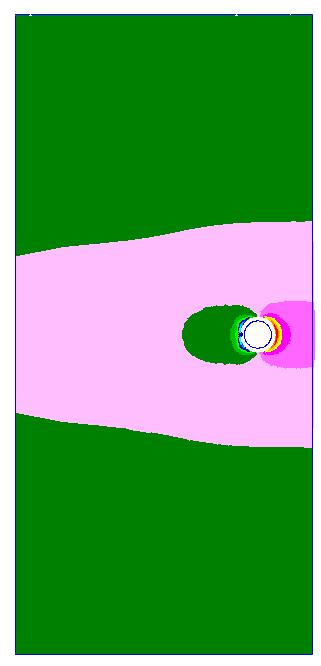
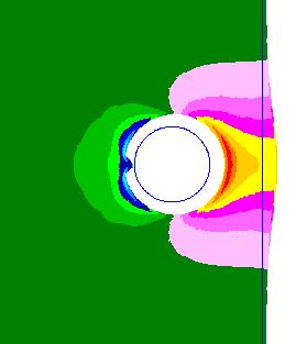
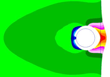
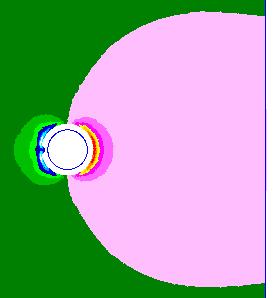
7 Example of Hole Cx Residual Stress Results Entrance Middle Exit Wide edge Narrow edge 7 DIC FE Comparison


8 Edge Margin Study: Deformations bulging Cx =4.68%, e/d=.8 Cx =4.68%, e/d=1.2 Cx =4.68%, e/d=2. Cx =4.68%, e/d=5. 8
9 Edge Margin 3 Cx=4., Narrow edge Effects on hoop (tangential) stress after cold expansion (narrow edge) Compression at hole edge e/d compression at Entrance e/d tensile Tangential stress (MPa) yield Cx=4., Narrow edge Cx=4.%, e/d=5., Middle Cx=4.%, e/d=2., Middle Cx=4.%, e/d=1.2, Middle Cx=4.%, e/d=.8, Middle Distance from hole edge (mm) Tangential stress (MPa) Tangential stress (MPa) Cx=4.%, e/d=5., Entrance Cx=4.%, e/d=2., Entrance Cx=4.%, e/d=1.2, Entrance Cx=4.%, e/d=.8, Entrance yield Distance from hole edge (mm) Cx=4., Narrow edge Cx=4.%, e/d=5., Exit Cx=4.%, e/d=2., Exit Cx=4.%, e/d=1.2, Exit Cx=4.%, e/d=.8, Exit Distance from hole edge (mm) 9
10 Tangential stress (MPa) Tangential stress (MPa) Edge Margin Effects on hoop (tangential) stress under 1 MPa tension (narrow edge) Low stress at hole edge e/d tensile e/d compression at Entrance Without Cx Tangential stress (MPa) With & without Cx, tension, narrow edge yield Cx=4.%, e/d=5., tension, Middle Cx=4.%, e/d=2., tension, Middle Cx=4.%, e/d=1.2, tension, Middle Cx=4.%, e/d=.8, tension, Middle e/d=5., tension, Middle e/d=2., tension, Middle e/d=1.2, tension, Middle e/d=.8, tension, Middle Distance from hole edge (mm) 4 3 With & without Cx, tension, narrow edge yield 4 3 With & without Cx, tension, narrow edge Cx=4.%, e/d=5., tension, Entrance Cx=4.%, e/d=2., tension, Entrance Cx=4.%, e/d=1.2, tension, Entrance Cx=4.%, e/d=.8, tension, Entrance e/d=5., tension, Entrance e/d=2., tension, Entrance e/d=1.2, tension, Entrance Distance from hole edge (mm) Cx=4.%, e/d=5., tension, Exit Cx=4.%, e/d=2., tension, Exit Cx=4.%, e/d=1.2, tension, Exit Cx=4.%, e/d=.8, tension, Exit e/d=5., tension, Exit e/d=2., tension, Exit e/d=1.2, tension, Exit e/d=.8, tension, Exit Distance from hole edge (mm) 1
11 Cx Level Effects on hoop (tangential) stress after cold expansion (narrow edge) Tangential stress (MPa) Compression at hole edge Cx tension Cx compression e/d=2., narrow edge Cx=4.68%, e/d=2., Middle Cx=4.%, e/d=2. Middle Cx=3.5%, e/d=2. Middle Cx=3.%, e/d=2. Middle Distance from hole edge (mm) Tangential stress (MPa) Tangential stress (MPa) e/d=2., narrowedge Cx=4.68%, e/d=2., Entrance Cx=4.%, e/d=2., Entrance Cx=3.5%, e/d=2., Entrance Cx=3.%, e/d=2., Entrance Distance from hole edge (mm) e/d=2., narrow edge Cx=4.68%, e/d=2., Exit Cx=4.%, e/d=2. Exit Cx=3.5%, e/d=2. Exit Cx=3.%, e/d=2. Exit Distance from hole edge (mm) 11
12 Sleeve Split Orientation Effects on hoop (tangential) stress after cold expansion (narrow edge) Effect on Entrance side Tangential stress (MPa) Cx=4., e/d=2., edge Cx=4.%, e/d=2., gap=, Entrance Cx=4.%, e/d=2., gap=45, Entrance Cx=4.%, e/d=2., gap=9, Entrance Cx=4.%, e/d=2., gap=135, Entrance Cx=4.%, e/d=2., gap=18, Entrance Distance from hole edge (mm) Tangential stress (MPa) Cx=4., e/d=2., edge Cx=4.%, e/d=2., gap=, Middle -2 Cx=4.%, e/d=2., gap=45, Middle -3 Cx=4.%, e/d=2., gap=9, Middle -4 Cx=4.%, e/d=2., gap=135, Middle -5 Cx=4.%, e/d=2., gap=18, Middle Distance from hole edge (mm) Tangential stress (MPa) Cx=4., e/d=2., edge Cx=4.%, e/d=2., gap=, Exit Cx=4.%, e/d=2., gap=45, Exit Cx=4.%, e/d=2., gap=9, Exit Cx=4.%, e/d=2., gap=135, Exit Cx=4.%, e/d=2., gap=18, Exit Distance from hole edge (mm) 12
 2 15 1 5-5 -1-15 -2-25 Cx=4., e/d=2., edge Cx=4.%, e/d=2.")
 o 45 o 9 o 135 o 18 o 13")
13 Sleeve Split Orientation Effects on hoop (tangential) stress after cold expansion (narrow edge) Effect on Entrance side Tangential stress (MPa) Cx=4., e/d=2., edge Cx=4.%, e/d=2., gap=, Entrance Cx=4.%, e/d=2., gap=45, Entrance Cx=4.%, e/d=2., gap=9, Entrance Cx=4.%, e/d=2., gap=135, Entrance Cx=4.%, e/d=2., gap=18, Entrance Distance from hole edge (mm) o 45 o 9 o 135 o 18 o 13
14 Friction (Lubrication) 2 Cx=4., e/d=2., edge Effects on hoop (tangential) stress after cold expansion (between sleeve and mandrel / sleeve and hole bore) (narrow edge) No significant effect Tangential stress (MPa) Cx=4.%, e/d=2., frc=.1, Entrance Cx=4.%, e/d=2., frc=.3, Entrance Cx=4.%, e/d=2., frc=.5, Entrance Cx=4.%, e/d=2., frc=.8, Entrance Distance from hole edge (mm) Tangential stress (MPa) Cx=4., e/d=2.,, edge Cx=4.%, e/d=2., frc=.1, Middle Cx=4.%, e/d=2., frc=.3, Middle -4 Cx=4.%, e/d=2., frc=.5, Middle -5 Cx=4.%, e/d=2., frc=.8, Middle Distance from hole edge (mm) Tangential stress (MPa) Cx=4., e/d=2., edge Cx=4.%, e/d=2., frc=.1, Exit Cx=4.%, e/d=2., frc=.3, Exit Cx=4.%, e/d=2., frc=.5, Exit -4 Cx=4.%, e/d=2., frc=.8,, Exit Distance from hole edge (mm) 14
15 Sleeve Thickness Effects on hoop (tangential) stress after cold expansion (narrow edge) t compression at Entrance Tangential stress (MPa) Cx=4., e/d=2., edge -5 Cx=4.%, e/d=2., ts=.6, Entrance -1 Cx=4.%, e/d=2., ts=.8, Entrance Cx=4.%, e/d=2., ts=.12, Entrance -15 Cx=4.%, e/d=2., ts=.18, Entrance Distance from hole edge (mm) Cx=4., e/d=2.,, edge Cx=4., e/d=2., edge Tangential stress (MPa) Cx=4.%, e/d=2., ts=.6, Middle -3 Cx=4.%, e/d=2., ts=.8, Middle -4 Cx=4.%, e/d=2., ts=.12, Middle -5 Cx=4.%, e/d=2., ts=.18, Middle Distance from hole edge (mm) Tangential stress (MPa) Cx=4.%, e/d=2., ts=.6, Exit Cx=4.%, e/d=2., ts=.8, Exit -3 Cx=4.%, e/d=2., ts=.12, Exit -4 Cx=4.%, e/d=2., ts=.18, Exit Distance from hole edge (mm) 15
16 Strain (mm/mm) Comparison with Analytical Solutions and Digital Image Correlation (DIC) Test Strain Measurements.6 4--N, No ream N, No ream Strain (mm/mm) ε_r_ana ε_θ_ana -.8 ε_r_exp ε_θ_exp ε_r_entry_fea ε_θ_entry_fea ε_r_ana ε_θ_ana -.8 ε_r_(exp) ε_θ_(exp) -.1 ε_r_entry_fea ε_θ_entry_fea -.12 r/a (mm/mm) -.12 r/a (mm/mm) 16
17 Strain (mm/mm) Comparison with Analytical Solutions and Digital Image Correlation (DIC) Test Strain Measurements N, No ream.4 1--N, No ream ε_r_ana ε_θ_ana ε_r_(exp) ε_θ_(exp) -.8 ε_r_entry_fea ε_θ_entry_fea Strain (mm/mm) ε_r_ana ε_θ_ana ε_r_(exp) ε_θ_(exp) -.8 ε_r_entry_fea ε_θ_entry_fea -.1 r/a (mm/mm) -.1 r/a (mm/mm) 17
18 Brief Summary from parametric Study Low edge margins can lead to high deformation and high edge tension Entrance side displayed the most variability and least amount of Cx benefit Middle displayed most consistency and greatest amount of Cx benefit Cx technology shows clear benefits; however, there are obvious limitations for low edge margins 18
19 Residual Stresses Induced by Hole Cx Process Observations from FE Simulations: Uniform radial expansion resulted in higher compressive radial and hoop stresses A considerable through-the-thickness radial and hoop stress variation was observed Compressive hoop residual stresses are larger at the exit face than at the entrance face, which contains the smallest compressive (or even tensile ) hoop residual stresses Fatigue tests show that early crack nucleation and growth tend to occur primarily and more extensively at the mendrel entrance face 19


20 Interference Fit Fastener Modeling Hi-Lok fastener HL5-8-6 with HL9-8A collar 1- Insert fastener / hold disk 2- Release pusher 2- Apply pre-tension (torque) to fastener / collar Parametric study: Hole diameters (interference fits) 775-T651 plate No load transfer Edge margins Fastener Disk Collar 2


21 Interference Fit Fastener Modeling e/d = 2. e/d = 1.5 e/d = 1.2 e/d = 1. e/d =.8 21
22 Summary of Interference Fit Fastener Modeling Properly installed Hi-Lok fasteners will reduce the stress concentration effect at the hole edge by their clamping force and move the largest stressed areas from the surfaces to the mid-plane. A.35 induced interference fit was the best of the four values investigated (,.1,.35,.5 ) Effect of the low edge margin e/d was significant. At a e/d value less than 1.2, a highly localized tensile stress occurred in the remaining ligament, independent of the degree of interference fit 22

 Squeeze")

23 Riveting Simulation Countersunk fastener 1- Squeeze fastener 2- Release pusher Parametric study: Hole diameters (clearance) Squeeze displacement (head deformation) Def 1 Def 2 Size 1 Size 2 Size 3 (largest clearance) 23
24 Hoop stress (MPa) Riveting Simulation General Observations on Residual Stress Smaller diameters / Larger deformation resulted in compression at hole edge Larger compression is balanced by larger tension, at a larger distance from the hole Results agreed well with Neutron Diffraction measurements Transverse path position (mm) h Size1 Def1 Size 2 Def 1 Size 3 Def 1 Size1 Def2 Size 2 Def 2 Size 3 Def 2 Post-Riveting Residual Stress 24
25 Example: Crack Growth in Riveted Lap Joint Typical Lap Joint Geometry representative of a fuselage panel Three rows of countersunk rivets Analysis Objective Calculate life to first link-up distribution 25
26 Analysis Strategy Stress and Residual Stress Profiles Riveting simulation (MSC Marc) Crack Growth Analysis Countersunk geometry correction factor Riveting residual stress correction factor Spectrum modification based on tip position Residual stress correction factor AFGROW AFGROW AFGROW Monte Carlo Simulations (CanGROW) EIFS distribution calculation Life distribution calculation (to first link-up) 26


27 Riveting Simulation Global Model Shell model Displacements from applied loads Local Model Central region / Nine rivets 3D model / Multi-Step Analysis Riveting simulation Squeeze, release Cyclic loading 1 or 3 rivets 27

28 Finite Element Analysis Input Parameters Several hole diameters from specifications Squeeze displacement derived from test measurements Material properties from published data Model validated with strain survey 28
29 Hoop stress (MPa) Finite Element Analysis Local Model Analysis Results Post-riveting stress No load Stress under applied loads Max, min Open hole stress Max, min Include nonlinear effects: Material Geometry Contact Hole Transverse path position (mm) Residual Max Min Open hole Max Size 3 Def 2 (low compression at hole edge) Open hole Min 29
30 Beta Solution Riveting Residual Stress CanGROW: Does not have CSK model or residual stress capabilities yet Approach: Convert AFGROW s results to a Beta correction for constant amplitude loading (compounded with MSD factors) AFGROW: Approach 1: AFGROW CSK model Residual Stress option not available for CSK model Modify spectrum based on tip position (FE min and max stress) Approach 2: AFGROW Straight Hole Model Convert CSK Model to a Beta table Add post-riveting residual stress from FE 3
 Correction Factor 2.")
31 c (m) Beta Correction for CSK Geometry Countersunk Hole Solution Uses AFGROW s solution in CanGROW (through crack) Correction Factor (CF) = c_afgrow / c_cangrow E-2 2 Correction Factor CSK 8.E-3 CSK AFGROW CanGROW Through E-3 Mod CanGROW c 1 4.E-3.5 Thickness Initiation 1% Thickness.E c (m) Correction Factor 2.E Cycles Crack Growth 31
32 SMF (MPa) Stress Ratio Approach 1: AFGROW CSK Model Calculate SMF and R based on tip position Use FE min and max stress in AFGROW Calculated using FE open CSK hole model Incremental growth (VBA Program / COM interface) Original SMF Modified SMF.3.2 Original R Modified R c (m) -.2 Size 3 Def 2 (low compression at hole edge) c (m) 32
33 Approach 2: AFGROW Straight Hole Model Manual CSK Beta correction Residual stresses curve from FE Constant D is assumed AFGROW Straight Hole - Through Crack AFGROW CSK Extracted points AFGROW output (verification) 2 c direction a direction c (m) Size 3 Def 2 (low compression at hole edge) a, c (m) 33
34 Beta Solutions CSK Hole - AFGROW Auto CSK Hole - AFGROW Step-By-Step + Through CSK Hole + Res Stress - Approach 1 CSK Hole + Res Stress - Approach Correction Factor CSK CSK + Res. Stress - Approach CSK + Res. Stress - Approach 2 c c Thickness "Initiation" (.5 mm) 1% Thickness c (m).5 Thickness "Initiation" (.5 mm) 1% Thickness c (m) Beta curve (AFGROW) CanGROW Correction Factor Size 3 Def 2 (low compression at hole edge) 34
35 Crack Growth Approach 2 more severe than Approach 1 D assumed constant in Approach 2 Nonlinearities in FE results 35 Size 3 Def 2 (low compression at hole edge)

")
 Monte Carlo simulation life distribution")
36 Probabilistic Analysis Life to first link-up Option 1: Probabilistic initiation life (strain life using FE results) + Crack Growth Option 2: EIFS distribution based on in-service findings (including censored data) Crack Growth only CanGROW MSD analysis (crack interaction) Monte Carlo simulation life distribution (POF) CanGROW 36
37 Conclusion An overview of NRC s work on the calculation of residual stresses using 3D finite element modeling was presented These simulations replicate as closely as possible the actual processes by using 3D multi-step nonlinear analysis Hole cold expansion; Interference fit fastener installation; Riveting 3D and through-the-thickness effects were shown to be significant An example was presented, where life to first-linkup is to be calculated for a lap joint, using a series of three software tools: MSC Marc to calculate post-riveting residual stresses AFGROW to build a Beta factor for CSK geometry and FE stresses CanGROW to perform MSD Monte Carlo simulations 37
38 Possible Future Work Possible verification and improvement steps: Use StressCheck to develop Beta factors that includes the hole geometry and service and/or residual stresses determined by Cx or riveting simulation Additional test validation using digital image correlation, X-ray diffraction, contour method, etc. 38
39 Thank you Guillaume Renaud Research Officer Tel:
Residual Stresses in GLARE Laminates due to the Cold Expansion Process
 Residual Stresses in GLARE Laminates due to the Cold Expansion Process C.D. Rans a, R.C. Alderliesten b, P.V. Straznicky a a Department of Mechanical and Aerospace Engineering, Carleton University, 1125
MODELLING OF THE RIVET FORMING PROCESS IN ALUMINUM AND GLARE FOR DESIGN AGAINST FATIGUE
 MODELLING OF THE RIVET FORMING PROCESS IN ALUMINUM AND GLARE FOR DESIGN AGAINST FATIGUE Calvin D. Rans 1, René C. Alderliesten 2, Paul V. Straznicky 1 1 Department of Mechanical and Aerospace Engineering,
The University of Melbourne Engineering Mechanics
 The University of Melbourne 436-291 Engineering Mechanics Tutorial Four Poisson s Ratio and Axial Loading Part A (Introductory) 1. (Problem 9-22 from Hibbeler - Statics and Mechanics of Materials) A short
Transactions on Engineering Sciences vol 2, 1993 WIT Press, ISSN
 3-d axisymmetric numerical analysis and experimental study of the fastener hole coldworking process S.A. Forgues, M. Bernard, T. Bui-Quoc Applied Mechanics Section, Department of Mechanical Engineering,
THREE DIMENSIONAL STRESS ANALYSIS OF THE T BOLT JOINT
 THREE DIMENSIONAL STRESS ANALYSIS OF THE T BOLT JOINT Víctor Martínez 1, Alfredo Güemes 2, Norbert Blanco 1, Josep Costa 1 1 Escola Politècnica Superior. Universitat de Girona. Girona, Spain (17071) 2
[5] Stress and Strain
![[5] Stress and Strain](/thumbs/95/123344550.jpg "[5] Stress and Strain") [5] Stress and Strain Page 1 of 34 [5] Stress and Strain [5.1] Internal Stress of Solids [5.2] Design of Simple Connections (will not be covered in class) [5.3] Deformation and Strain [5.4] Hooke s Law
[5] Stress and Strain Page 1 of 34 [5] Stress and Strain [5.1] Internal Stress of Solids [5.2] Design of Simple Connections (will not be covered in class) [5.3] Deformation and Strain [5.4] Hooke s Law
Elasto Plastic 3D Finite Element Contact Analysis of a Hole Containing a Circular Insert in a Fatigue Test Coupon
 Elasto Plastic 3D Finite Element Contact Analysis of a Hole Containing a Circular Insert in a Fatigue Test Coupon Witold Waldman Aerospace Division Defence Science and Technology Group DST-Group-TR-3140
Solid Mechanics Homework Answers
 Name: Date: Solid Mechanics Homework nswers Please show all of your work, including which equations you are using, and circle your final answer. Be sure to include the units in your answers. 1. The yield
A Model for Local Plasticity Effects on Fatigue Crack Growth
 A Model for Local Plasticity Effects on Fatigue Crack Growth USAF Aircraft Structural Integrity Program Conference San Antonio, Texas November 28-30, 2006 R. Craig McClung Brian M. Gardner Yi-Der Lee Fraser
Stress Concentration. Professor Darrell F. Socie Darrell Socie, All Rights Reserved
 Stress Concentration Professor Darrell F. Socie 004-014 Darrell Socie, All Rights Reserved Outline 1. Stress Concentration. Notch Rules 3. Fatigue Notch Factor 4. Stress Intensity Factors for Notches 5.
Investigation of Aircraft Panel Deformations during Riveting Process
 Investigation of Aircraft Panel Deformations during Riveting Process Abdelal, G. F., Georgiou, G., Cooper, J., Murphy, A., Robotham, A., & Lunt, P. (2014). Investigation of Aircraft Panel Deformations
Stress Intensity Factor Determination of Multiple Straight and Oblique Cracks in Double Cover Butt Riveted Joint
 ISSN (Online) : 2319-8753 ISSN (Print) : 2347-671 International Journal of Innovative Research in Science, Engineering and Technology Volume 3, Special Issue 3, March 214 214 International Conference on
Tolerance Ring Improvement for Reducing Metal Scratch
 International Journal of Scientific and Research Publications, Volume 2, Issue 11, November 2012 1 Tolerance Ring Improvement for Reducing Metal Scratch Pattaraweerin Woraratsoontorn*, Pitikhate Sooraksa**
Stresses Analysis of Petroleum Pipe Finite Element under Internal Pressure
 ISSN : 48-96, Vol. 6, Issue 8, ( Part -4 August 06, pp.3-38 RESEARCH ARTICLE Stresses Analysis of Petroleum Pipe Finite Element under Internal Pressure Dr.Ragbe.M.Abdusslam Eng. Khaled.S.Bagar ABSTRACT
PES Institute of Technology
 PES Institute of Technology Bangalore south campus, Bangalore-5460100 Department of Mechanical Engineering Faculty name : Madhu M Date: 29/06/2012 SEM : 3 rd A SEC Subject : MECHANICS OF MATERIALS Subject
N = Shear stress / Shear strain
 UNIT - I 1. What is meant by factor of safety? [A/M-15] It is the ratio between ultimate stress to the working stress. Factor of safety = Ultimate stress Permissible stress 2. Define Resilience. [A/M-15]
Transactions on Modelling and Simulation vol 9, 1995 WIT Press, ISSN X
 Elastic-plastic model of crack growth under fatigue using the boundary element method M. Scibetta, O. Pensis LTAS Fracture Mechanics, University ofliege, B-4000 Liege, Belgium Abstract Life of mechanic
NUMERICAL SIMULATION OF TENSILE LOADED LAP RIVETED JOINT
 Journal of KONES Powertrain and Transport, Vol. 13, No. 3 NUMERICAL SIMULATION OF TENSILE LOADED LAP RIVETED JOINT Elżbieta Szymczyk, Agnieszka Derewońko, Andrzej Kiczko Military University of Technology
Random Variables. Gust and Maneuver Loads
 Random Variables An overview of the random variables was presented in Table 1 from Load and Stress Spectrum Generation document. Further details for each random variable are given below. Gust and Maneuver
Mechanics of Materials Primer
 Mechanics of Materials rimer Notation: A = area (net = with holes, bearing = in contact, etc...) b = total width of material at a horizontal section d = diameter of a hole D = symbol for diameter E = modulus
Special edition paper
 Development of New Aseismatic Structure Using Escalators Kazunori Sasaki* Atsushi Hayashi* Hajime Yoshida** Toru Masuda* Aseismatic reinforcement work is often carried out in parallel with improvement
Finite element simulations of fretting contact systems
 Computer Methods and Experimental Measurements for Surface Effects and Contact Mechanics VII 45 Finite element simulations of fretting contact systems G. Shi, D. Backman & N. Bellinger Structures and Materials
Ultimate shear strength of FPSO stiffened panels after supply vessel collision
 Ultimate shear strength of FPSO stiffened panels after supply vessel collision Nicolau Antonio dos Santos Rizzo PETROBRAS Rio de Janeiro Brazil Marcelo Caire SINTEF do Brasil Rio de Janeiro Brazil Carlos
Strength of Material. Shear Strain. Dr. Attaullah Shah
 Strength of Material Shear Strain Dr. Attaullah Shah Shear Strain TRIAXIAL DEFORMATION Poisson's Ratio Relationship Between E, G, and ν BIAXIAL DEFORMATION Bulk Modulus of Elasticity or Modulus of Volume
MECE 3321 MECHANICS OF SOLIDS CHAPTER 3
 MECE 3321 MECHANICS OF SOLIDS CHAPTER 3 Samantha Ramirez TENSION AND COMPRESSION TESTS Tension and compression tests are used primarily to determine the relationship between σ avg and ε avg in any material.
COURSE TITLE : APPLIED MECHANICS & STRENGTH OF MATERIALS COURSE CODE : 4017 COURSE CATEGORY : A PERIODS/WEEK : 6 PERIODS/ SEMESTER : 108 CREDITS : 5
 COURSE TITLE : APPLIED MECHANICS & STRENGTH OF MATERIALS COURSE CODE : 4017 COURSE CATEGORY : A PERIODS/WEEK : 6 PERIODS/ SEMESTER : 108 CREDITS : 5 TIME SCHEDULE MODULE TOPICS PERIODS 1 Simple stresses
FE-Analysis of Stringer-to-floor-beam Connections in Riveted Railway Bridges
 FE-Analysis of Stringer-to-floor-beam Connections in Riveted Railway Bridges By Mohammad Al-Emrani 1 and Robert Kliger 2 Department of Structural Engineering Chalmers University of Technology, SE-412 96
Advanced Software for Integrated Probabilistic Damage Tolerance Analysis Including Residual Stress Effects
 Advanced Software for Integrated Probabilistic Damage Tolerance Analysis Including Residual Stress Effects Residual Stress Summit 2010 Tahoe City, California September 26-29, 2010 Michael P. Enright R.
Chapter Two: Mechanical Properties of materials
 Chapter Two: Mechanical Properties of materials Time : 16 Hours An important consideration in the choice of a material is the way it behave when subjected to force. The mechanical properties of a material
D e s i g n o f R i v e t e d J o i n t s, C o t t e r & K n u c k l e J o i n t s
 D e s i g n o f R i v e t e d J o i n t s, C o t t e r & K n u c k l e J o i n t s 1. Design of various types of riveted joints under different static loading conditions, eccentrically loaded riveted joints.
EDEM DISCRETIZATION (Phase II) Normal Direction Structure Idealization Tangential Direction Pore spring Contact spring SPRING TYPES Inner edge Inner d
 Normal Direction Structure Idealization Tangential Direction Pore spring Contact spring SPRING TYPES Inner edge Inner d") Institute of Industrial Science, University of Tokyo Bulletin of ERS, No. 48 (5) A TWO-PHASE SIMPLIFIED COLLAPSE ANALYSIS OF RC BUILDINGS PHASE : SPRING NETWORK PHASE Shanthanu RAJASEKHARAN, Muneyoshi
Institute of Industrial Science, University of Tokyo Bulletin of ERS, No. 48 (5) A TWO-PHASE SIMPLIFIED COLLAPSE ANALYSIS OF RC BUILDINGS PHASE : SPRING NETWORK PHASE Shanthanu RAJASEKHARAN, Muneyoshi
PROBLEM #1.1 (4 + 4 points, no partial credit)
") PROBLEM #1.1 ( + points, no partial credit A thermal switch consists of a copper bar which under elevation of temperature closes a gap and closes an electrical circuit. The copper bar possesses a length
PROBLEM #1.1 ( + points, no partial credit A thermal switch consists of a copper bar which under elevation of temperature closes a gap and closes an electrical circuit. The copper bar possesses a length
Aim of the study Experimental determination of mechanical parameters Local buckling (wrinkling) Failure maps Optimization of sandwich panels
 Failure maps Optimization of sandwich panels") METNET Workshop October 11-12, 2009, Poznań, Poland Experimental and numerical analysis of sandwich metal panels Zbigniew Pozorski, Monika Chuda-Kowalska, Robert Studziński, Andrzej Garstecki Poznan University
METNET Workshop October 11-12, 2009, Poznań, Poland Experimental and numerical analysis of sandwich metal panels Zbigniew Pozorski, Monika Chuda-Kowalska, Robert Studziński, Andrzej Garstecki Poznan University
ME 243. Mechanics of Solids
 ME 243 Mechanics of Solids Lecture 2: Stress and Strain Ahmad Shahedi Shakil Lecturer, Dept. of Mechanical Engg, BUET E-mail: sshakil@me.buet.ac.bd, shakil6791@gmail.com Website: teacher.buet.ac.bd/sshakil
NONLINEAR LOCAL BENDING RESPONSE AND BULGING FACTORS FOR LONGITUDINAL AND CIRCUMFERENTIAL CRACKS IN PRESSURIZED CYLINDRICAL SHELLS
 NONINEAR OA BENDING RESPONSE AND BUGING FATORS FOR ONGITUDINA AND IRUMFERENTIA RAKS IN PRESSURIZED YINDRIA SHES Richard D. Young, * heryl A. Rose, * and James H. Starnes, Jr. NASA angley Research enter
Design of a fastener based on negative Poisson's ratio foam adapted from
 1 Design of a fastener based on negative Poisson's ratio foam adapted from Choi, J. B. and Lakes, R. S., "Design of a fastener based on negative Poisson's ratio foam", Cellular Polymers, 10, 205-212 (1991).
High Tech High Top Hat Technicians. An Introduction to Solid Mechanics. Is that supposed to bend there?
 High Tech High Top Hat Technicians An Introduction to Solid Mechanics Or Is that supposed to bend there? Why don't we fall through the floor? The power of any Spring is in the same proportion with the
EMA 3702 Mechanics & Materials Science (Mechanics of Materials) Chapter 2 Stress & Strain - Axial Loading
 Chapter 2 Stress & Strain - Axial Loading") MA 3702 Mechanics & Materials Science (Mechanics of Materials) Chapter 2 Stress & Strain - Axial Loading MA 3702 Mechanics & Materials Science Zhe Cheng (2018) 2 Stress & Strain - Axial Loading Statics
MA 3702 Mechanics & Materials Science (Mechanics of Materials) Chapter 2 Stress & Strain - Axial Loading MA 3702 Mechanics & Materials Science Zhe Cheng (2018) 2 Stress & Strain - Axial Loading Statics
CHAPTER 7 FINITE ELEMENT ANALYSIS OF DEEP GROOVE BALL BEARING
 113 CHAPTER 7 FINITE ELEMENT ANALYSIS OF DEEP GROOVE BALL BEARING 7. 1 INTRODUCTION Finite element computational methodology for rolling contact analysis of the bearing was proposed and it has several
FATIGUE DESIGN PROCEDURE OF LONGITUDINAL AND TRANSVERSE FUSELAGE JOINTS
 28 TH INTERNATIONAL CONGRESS OF THE AERONAUTICAL SCIENCES FATIGUE DESIGN PROCEDURE OF LONGITUDINAL AND TRANSVERSE FUSELAGE JOINTS Basov V.N. and Dr Pankov A.V TsAGI andrey.pankov@tsagi.ru eywords: fatigue,
Determination of Stress Intensity Factor for a Crack Emanating From a Rivet Hole and Approaching Another in Curved Sheet
 International OPEN ACCESS Journal Of Modern Engineering Research (IJMER) Determination of Stress Intensity Factor for a Crack Emanating From a Rivet Hole and Approaching Another in Curved Sheet Raghavendra.
: APPLIED MECHANICS & STRENGTH OF MATERIALS COURSE CODE : 4021 COURSE CATEGORY : A PERIODS/ WEEK : 5 PERIODS/ SEMESTER : 75 CREDIT : 5 TIME SCHEDULE
 COURSE TITLE : APPLIED MECHANICS & STRENGTH OF MATERIALS COURSE CODE : 4021 COURSE CATEGORY : A PERIODS/ WEEK : 5 PERIODS/ SEMESTER : 75 CREDIT : 5 TIME SCHEDULE MODULE TOPIC PERIODS 1 Simple stresses
Chapter 5. Vibration Analysis. Workbench - Mechanical Introduction ANSYS, Inc. Proprietary 2009 ANSYS, Inc. All rights reserved.
 Workbench - Mechanical Introduction 12.0 Chapter 5 Vibration Analysis 5-1 Chapter Overview In this chapter, performing free vibration analyses in Simulation will be covered. In Simulation, performing a
Name :. Roll No. :... Invigilator s Signature :.. CS/B.TECH (CE-NEW)/SEM-3/CE-301/ SOLID MECHANICS
/SEM-3/CE-301/ SOLID MECHANICS") Name :. Roll No. :..... Invigilator s Signature :.. 2011 SOLID MECHANICS Time Allotted : 3 Hours Full Marks : 70 The figures in the margin indicate full marks. Candidates are required to give their answers
Name :. Roll No. :..... Invigilator s Signature :.. 2011 SOLID MECHANICS Time Allotted : 3 Hours Full Marks : 70 The figures in the margin indicate full marks. Candidates are required to give their answers
Samantha Ramirez, MSE
 Samantha Ramirez, MSE Centroids The centroid of an area refers to the point that defines the geometric center for the area. In cases where the area has an axis of symmetry, the centroid will lie along
Optimum Height of Plate Stiffener under Pressure Effect
 The st Regional Conference of Eng. Sci. NUCEJ Spatial ISSUE vol., No.3, 8 pp 459-468 Optimum Height of Plate Stiffener under Pressure Effect Mazin Victor Yousif M.Sc Production Engineering University of
Example-3. Title. Description. Cylindrical Hole in an Infinite Mohr-Coulomb Medium
 Example-3 Title Cylindrical Hole in an Infinite Mohr-Coulomb Medium Description The problem concerns the determination of stresses and displacements for the case of a cylindrical hole in an infinite elasto-plastic
Direct and Shear Stress
 Direct and Shear Stress 1 Direct & Shear Stress When a body is pulled by a tensile force or crushed by a compressive force, the loading is said to be direct. Direct stresses are also found to arise when
Stress Analysis Of Riveted Butt Joint
 International Journal of Engineering Research & Technology (IJERT) ISSN: 22711 Vol. 2 Issue, August 213 Analysis Of Riveted Butt Joint K. S. Bodadkar *1 * Pg. student of Department of Mechanical Engineering
Stress-Strain Behavior
 Stress-Strain Behavior 6.3 A specimen of aluminum having a rectangular cross section 10 mm 1.7 mm (0.4 in. 0.5 in.) is pulled in tension with 35,500 N (8000 lb f ) force, producing only elastic deformation.
1 Input data. Profis Anchor Company: Specifier: Address: Phone I Fax: Page: Project: Sub-Project I Pos. No.
 1 Specifier's comments: Check of Existing Base plate (B6)- According to max. forces on Node No. 11979, LC 1.4(D.L.+WX) 1 Input data Anchor type and diameter: HIT-HY 200 + HIT-V-F (8.8) M27 Seismic/Filling
Mechanics of Solids. Mechanics Of Solids. Suraj kr. Ray Department of Civil Engineering
 Mechanics Of Solids Suraj kr. Ray (surajjj2445@gmail.com) Department of Civil Engineering 1 Mechanics of Solids is a branch of applied mechanics that deals with the behaviour of solid bodies subjected
Practice Final Examination. Please initial the statement below to show that you have read it
 EN175: Advanced Mechanics of Solids Practice Final Examination School of Engineering Brown University NAME: General Instructions No collaboration of any kind is permitted on this examination. You may use
1 Input data. Profis Anchor Company: Specifier: Address: Phone I Fax: Page: Project: Sub-Project I Pos. No.
 1 Specifier's comments: Design of Typical Baseplate B1 according to Max. forces in Node No. (5984), LC19 (1.2D+1.6S+0.8WY CASE B) 1 Input data Anchor type and diameter: HIT-HY 200 + HIT-V (8.8) M24 Seismic/Filling
FCP Short Course. Ductile and Brittle Fracture. Stephen D. Downing. Mechanical Science and Engineering
 FCP Short Course Ductile and Brittle Fracture Stephen D. Downing Mechanical Science and Engineering 001-015 University of Illinois Board of Trustees, All Rights Reserved Agenda Limit theorems Plane Stress
Table of Contents. Preface...xvii. Part 1. Level
 Preface...xvii Part 1. Level 1... 1 Chapter 1. The Basics of Linear Elastic Behavior... 3 1.1. Cohesion forces... 4 1.2. The notion of stress... 6 1.2.1. Definition... 6 1.2.2. Graphical representation...
Testing and Analysis
 Testing and Analysis Testing Elastomers for Hyperelastic Material Models in Finite Element Analysis 2.6 2.4 2.2 2.0 1.8 1.6 1.4 Biaxial Extension Simple Tension Figure 1, A Typical Final Data Set for Input
Multiaxial Fatigue. Professor Darrell F. Socie. Department of Mechanical Science and Engineering University of Illinois at Urbana-Champaign
 Multiaxial Fatigue Professor Darrell F. Socie Department of Mechanical Science and Engineering University of Illinois at Urbana-Champaign 2001-2011 Darrell Socie, All Rights Reserved Contact Information
Tuesday, February 11, Chapter 3. Load and Stress Analysis. Dr. Mohammad Suliman Abuhaiba, PE
 1 Chapter 3 Load and Stress Analysis 2 Chapter Outline Equilibrium & Free-Body Diagrams Shear Force and Bending Moments in Beams Singularity Functions Stress Cartesian Stress Components Mohr s Circle for
6.4 A cylindrical specimen of a titanium alloy having an elastic modulus of 107 GPa ( psi) and
 and") 6.4 A cylindrical specimen of a titanium alloy having an elastic modulus of 107 GPa (15.5 10 6 psi) and an original diameter of 3.8 mm (0.15 in.) will experience only elastic deformation when a tensile
6.4 A cylindrical specimen of a titanium alloy having an elastic modulus of 107 GPa (15.5 10 6 psi) and an original diameter of 3.8 mm (0.15 in.) will experience only elastic deformation when a tensile
University of Sheffield The development of finite elements for 3D structural analysis in fire
 The development of finite elements for 3D structural analysis in fire Chaoming Yu, I. W. Burgess, Z. Huang, R. J. Plank Department of Civil and Structural Engineering StiFF 05/09/2006 3D composite structures
Nonlinear Modeling for Health Care Applications Ashutosh Srivastava Marc Horner, Ph.D. ANSYS, Inc.
 Nonlinear Modeling for Health Care Applications Ashutosh Srivastava Marc Horner, Ph.D. ANSYS, Inc. 2 Motivation 12 Motivation Linear analysis works well for only small number of applications. The majority
Study of Contact Behavior in the Pre-squeeze Stage of
 Study of Contact Behavior in the Pre-squeeze Stage of Aluminum Alloy Resistance Spot Welding Li. Baoqing, Shan Ping Lian Jinrui, Hu Shengsun Tianjin University, Tianjin, P.R.C Abstract In this paper, an
Investigation of basic elements loading and tension of heavy hydraulic presses for metallurgical production
 Investigation of basic elements loading and tension of heavy hydraulic presses for metallurgical production Ganush V. I. National metallurgical academe of Ukraine Ostroverhov N. P., Sultan A. V., Dzichkovky
FINITE ELEMENT ANALYSIS OF TAPERED COMPOSITE PLATE GIRDER WITH A NON-LINEAR VARYING WEB DEPTH
 Journal of Engineering Science and Technology Vol. 12, No. 11 (2017) 2839-2854 School of Engineering, Taylor s University FINITE ELEMENT ANALYSIS OF TAPERED COMPOSITE PLATE GIRDER WITH A NON-LINEAR VARYING
MECE 3321: Mechanics of Solids Chapter 6
 MECE 3321: Mechanics of Solids Chapter 6 Samantha Ramirez Beams Beams are long straight members that carry loads perpendicular to their longitudinal axis Beams are classified by the way they are supported
Theory at a Glance (for IES, GATE, PSU)
") 1. Stress and Strain Theory at a Glance (for IES, GATE, PSU) 1.1 Stress () When a material is subjected to an external force, a resisting force is set up within the component. The internal resistance force
1. Stress and Strain Theory at a Glance (for IES, GATE, PSU) 1.1 Stress () When a material is subjected to an external force, a resisting force is set up within the component. The internal resistance force
Structural behaviour of traditional mortise-and-tenon timber joints
 Structural behaviour of traditional mortise-and-tenon timber joints Artur O. Feio 1, Paulo B. Lourenço 2 and José S. Machado 3 1 CCR Construtora S.A., Portugal University Lusíada, Portugal 2 University
PREDICTION OF OUT-OF-PLANE FAILURE MODES IN CFRP
 PREDICTION OF OUT-OF-PLANE FAILURE MODES IN CFRP R. R. Pinto 1, P. P. Camanho 2 1 INEGI - Instituto de Engenharia Mecanica e Gestao Industrial, Rua Dr. Roberto Frias, 4200-465, Porto, Portugal 2 DEMec,
NUMERICAL MODELLING OF COMPOSITE PIN- JOINTS AND EXPERIMENTAL VALIDATION
 NUMERICAL MODELLING OF COMPOSITE PIN- JOINTS AND EXPERIMENTAL VALIDATION Fabrice PIERRON*, François CERISIER*, and Michel GRÉDIAC** * SMS/ Département Mécanique et Matériaux, École Nationale Supérieure
Prediction of the bilinear stress-strain curve of engineering material by nanoindentation test
 Prediction of the bilinear stress-strain curve of engineering material by nanoindentation test T.S. Yang, T.H. Fang, C.T. Kawn, G.L. Ke, S.Y. Chang Institute of Mechanical & Electro-Mechanical Engineering,
Shape Optimization of Oldham Coupling in Scroll Compressor
 Purdue University Purdue e-pubs International Compressor Engineering Conference School of Mechanical Engineering 24 Shape Optimization of Oldham Coupling in Scroll Compressor In Hwe Koo LG Electronics
For ASME Committee use only.
 ð15þ KD-232 PROTECTION AGAINST LOCAL FAILURE In addition to demonstrating protection against plastic collapse as defined in KD-231, the local failure criteria below shall be satisfied. KD-232.1 Elastic
Mookambigai College of Engineering, Pudukkottai, Tamil Nadu, India
 ISSN XXXX XXXX 2017 IJESC Research Article Volume 7 Issue No.6 Structural Optimization of ER Spring Collet for Maximized Gripping Action Ram Prasad. S 1, Pravin Kumar. N 2, Jerry Andrew Fabian. S 3 M.E
Parameter study and a numerical model of mechanical roller expansion of tube-tubesheet joint
 THE 5 th STUDENT SYMPOSIUM ON MECHANICAL AND MANUFACTURING ENGINEERING Parameter study and a numerical model of mechanical roller expansion of tube-tubesheet joint D. Alexouli, D. Bøjesen, L. R. Bøystrup,
QUESTION BANK SEMESTER: III SUBJECT NAME: MECHANICS OF SOLIDS
 QUESTION BANK SEMESTER: III SUBJECT NAME: MECHANICS OF SOLIDS UNIT 1- STRESS AND STRAIN PART A (2 Marks) 1. Define longitudinal strain and lateral strain. 2. State Hooke s law. 3. Define modular ratio,
Numerical and Experimental Investigation of Aircraft Panel Deformations During Riveting Process
 Numerical and Experimental Investigation of Aircraft Panel Deformations During Riveting Process Abdelal, G. F., Georgiou, G., Cooper, J., Robotham, A., Levers, A., & Lunt, P. (2015). Numerical and Experimental
Effect of Deformation Mode of Cylindrical Tubes with Corrugated Surface Dimensional Errors
 Proceedings of the 8th International Conference on Innovation & Management 5 Effect of Deformation Mode of Cylindrical Tubes with Corrugated Surface Dimensional Errors Shigeyuki Haruyama, Daiheng Chen,
STRUCTURAL ANALYSIS OF THE LIFTING DEVICE DETECTOR SUPPORTS FOR THE LHCb VERTEX LOCATOR (VELO)
") National Institute for Nuclear Physics and High Energy Physics Kruislaan 409 1098 SJ Amsterdam The Netherlands NIKHEF Reference no.: MT-VELO 04-2 EDMS no: 466608 OF THE LIFTING DEVICE DETECTOR SUPPORTS
National Institute for Nuclear Physics and High Energy Physics Kruislaan 409 1098 SJ Amsterdam The Netherlands NIKHEF Reference no.: MT-VELO 04-2 EDMS no: 466608 OF THE LIFTING DEVICE DETECTOR SUPPORTS
Edward C. Robison, PE, SE. 02 January Architectural Metal Works ATTN: Sean Wentworth th ST Emeryville, CA 94608
 Edward C. Robison, PE, SE ks ATTN: Sean Wentworth 1483 67 th ST Emeryville, CA 94608 02 January 2013 SUBJ: 501 CORTE MADERA AVE, CORTE MADERA, CA 94925 BALCONY GUARD BASE PLATE MOUNTS The guards for the
PDDC 1 st Semester Civil Engineering Department Assignments of Mechanics of Solids [ ] Introduction, Fundamentals of Statics
![PDDC 1 st Semester Civil Engineering Department Assignments of Mechanics of Solids [ ] Introduction, Fundamentals of Statics](/thumbs/92/109382806.jpg "PDDC 1 st Semester Civil Engineering Department Assignments of Mechanics of Solids [ ] Introduction, Fundamentals of Statics") Page1 PDDC 1 st Semester Civil Engineering Department Assignments of Mechanics of Solids [2910601] Introduction, Fundamentals of Statics 1. Differentiate between Scalar and Vector quantity. Write S.I.
Page1 PDDC 1 st Semester Civil Engineering Department Assignments of Mechanics of Solids [2910601] Introduction, Fundamentals of Statics 1. Differentiate between Scalar and Vector quantity. Write S.I.
Design against fluctuating load
 Design against fluctuating load In many applications, the force acting on the spring is not constants but varies in magnitude with time. The valve springs of automotive engine subjected to millions of
MODELLING NON-LINEAR BEHAVIOUR OF STEEL FIBRE REINFORCED CONCRETE
 6th RILEM Symposium on Fibre-Reinforced Concretes (FRC) - BEFIB - September, Varenna, Italy MODELLING NON-LINEAR BEHAVIOUR OF STEEL FIBRE REINFORCED CONCRETE W. A. Elsaigh, J. M. Robberts and E.P. Kearsley
THE INFLUENCE OF RESIDUAL STRESS ON FATIGUE CRACK GROWTH. James E. LaRue
 THE INFLUENCE OF RESIDUAL STRESS ON FATIGUE CRACK GROWTH By James E. LaRue A Thesis Submitted to the Faculty of Mississippi State University in Partial Fulfillment of the Requirements for the Degree of
Fracture Analysis of Three Dimensional Elliptical Crack for Al7075-T651 Plate with Holes
 Indian Journal of Science and Technology, Vol 9(34), DOI: 10.17485/ijst/2016/v9i34/100846, September 2016 ISSN (Print) : 0974-6846 ISSN (Online) : 0974-5645 Fracture Analysis of Three Dimensional Elliptical
Sensitivity and Reliability Analysis of Nonlinear Frame Structures
 Sensitivity and Reliability Analysis of Nonlinear Frame Structures Michael H. Scott Associate Professor School of Civil and Construction Engineering Applied Mathematics and Computation Seminar April 8,
ARTICLE A-8000 STRESSES IN PERFORATED FLAT PLATES
 ARTICLE A-8000 STRESSES IN PERFORATED FLAT PLATES Delete endnote 18, which says "Express metric values in exponential form" A-8100 INTRODUCTION A-8110 SCOPE (a) This Article contains a method of analysis
NAME: Given Formulae: Law of Cosines: Law of Sines:
 NME: Given Formulae: Law of Cosines: EXM 3 PST PROBLEMS (LESSONS 21 TO 28) 100 points Thursday, November 16, 2017, 7pm to 9:30, Room 200 You are allowed to use a calculator and drawing equipment, only.
STANDARD SAMPLE. Reduced section " Diameter. Diameter. 2" Gauge length. Radius
 MATERIAL PROPERTIES TENSILE MEASUREMENT F l l 0 A 0 F STANDARD SAMPLE Reduced section 2 " 1 4 0.505" Diameter 3 4 " Diameter 2" Gauge length 3 8 " Radius TYPICAL APPARATUS Load cell Extensometer Specimen
Massachusetts Institute of Technology Department of Mechanical Engineering Cambridge, MA 02139
 Massachusetts Institute of Technology Department of Mechanical Engineering Cambridge, MA 02139 2.002 Mechanics and Materials II Spring 2004 Laboratory Module No. 6 Fracture Toughness Testing and Residual
Advanced Structural Analysis EGF Cylinders Under Pressure
 Advanced Structural Analysis EGF316 4. Cylinders Under Pressure 4.1 Introduction When a cylinder is subjected to pressure, three mutually perpendicular principal stresses will be set up within the walls
Using Thermal Boundary Conditions in SOLIDWORKS Simulation to Simulate a Press Fit Connection
 Using Thermal Boundary Conditions in SOLIDWORKS Simulation to Simulate a Press Fit Connection Simulating a press fit condition in SOLIDWORKS Simulation can be very challenging when there is a large amount
TECHNICAL REPORT BALLTEC LTD. FINITE ELEMENT ANAYLSIS AND FATIGUE ASSESSMENT OF KN ANCHOR CONNECTOR REPORT NO REVISION NO.
 BALLTEC LTD. FINITE ELEMENT ANAYLSIS AND FATIGUE ASSESSMENT OF 11300 KN ANCHOR CONNECTOR REPORT NO. 2004-3463 REVISION NO. 01 DET NORSKE VERITAS Date of first issue: Project No.: 2004-10-19 71524015 Approved
Multi Disciplinary Delamination Studies In Frp Composites Using 3d Finite Element Analysis Mohan Rentala
 Multi Disciplinary Delamination Studies In Frp Composites Using 3d Finite Element Analysis Mohan Rentala Abstract: FRP laminated composites have been extensively used in Aerospace and allied industries
σ = Eα(T T C PROBLEM #1.1 (4 + 4 points, no partial credit)
") PROBLEM #1.1 (4 + 4 points, no partial credit A thermal switch consists of a copper bar which under elevation of temperature closes a gap and closes an electrical circuit. The copper bar possesses a length
PROBLEM #1.1 (4 + 4 points, no partial credit A thermal switch consists of a copper bar which under elevation of temperature closes a gap and closes an electrical circuit. The copper bar possesses a length
Mechanical analysis of timber connection using 3D finite element model
 Mechanical analysis of timber connection using 3D finite element model Bohan XU Ph.D Student Civil Engineering Laboratory (CUST) Clermont-Ferrand, France Mustapha TAAZOUNT Dr-Ing Civil Engineering Laboratory
Failure Analysis of Unidirectional Composite Pinned- Joints
 217 IJEDR Volume, Issue 4 ISSN: 2321-9939 Failure Analysis of Unidirectional Composite Pinned- Joints 1 Sai Ashok.M, 2 Mr. U. Koteswara Rao 1 M-tech Machine Design, 2 Associate Professor & Asst. COE 1
MIL-HDBK-5H 1 December 1998
 components are calculated. In some cases, the methods presented are empirical and subject to further refinements. Any further expansion of information on element behavior in MIL-HDBK-5 will emphasize those
Samantha Ramirez, MSE. Stress. The intensity of the internal force acting on a specific plane (area) passing through a point. F 2
 passing through a point. F 2") Samantha Ramirez, MSE Stress The intensity of the internal force acting on a specific plane (area) passing through a point. Δ ΔA Δ z Δ 1 2 ΔA Δ x Δ y ΔA is an infinitesimal size area with a uniform force
Samantha Ramirez, MSE Stress The intensity of the internal force acting on a specific plane (area) passing through a point. Δ ΔA Δ z Δ 1 2 ΔA Δ x Δ y ΔA is an infinitesimal size area with a uniform force
Investigation into the Self-loosening Trend of Bolt Joints on the Tower Crane ShengChun Wang1,a, PeiWei Ni1,b, Ye Zhang1,c and MingXiao Dong1,2,d
 2nd International Conference on Advances in Mechanical Engineering and Industrial Informatics (AMEII 2016) Investigation into the Self-loosening Trend of Bolt Joints on the Tower Crane ShengChun Wang1,a,