DEPARTMENT OF NUCLEAR ENGINEERING GRADUATE SCHOOL OF NUCLEAR AND ALLIED SCIENCES UNIVERSITY OF GHANA, LEGON. B.Sc. (KNUST), 2001
|
|
|
- Griffin Bruce
- 5 years ago
- Views:
Transcription

, 2001 In partial fulfillment of the requirements for the award of M A STER OF PH ILOSO PH Y")
1 TH ER M A L ANALYSIS OF A PEBBLE BED H IG H TEM PER A TU R E GAS COOLED R EA C TO R A Thesis submitted to the: DEPARTMENT OF NUCLEAR ENGINEERING GRADUATE SCHOOL OF NUCLEAR AND ALLIED SCIENCES UNIVERSITY OF GHANA, LEGON BY STEPHEN YAM O AH ( ) B.Sc. (KNUST), 2001 In partial fulfillment of the requirements for the award of M A STER OF PH ILOSO PH Y in NUCLEAR ENGINEERING D EG REE June, 2009

2 W l - t c -


3 D E C L A R A T IO N I hereby declare that with the exception of references to other people s work which have duly been acknowledged, the compilation o f the Thesis submitted to the University o f Ghana, Legon for the degree leading to an award of Master of Philosophy (M.Phil) in Nuclear Engineering is the result of my own research work under the supervision of Prof. E. H. K. Akaho and Nana Prof. Akwasi G. Ayensu and that no part of this work has been presented for another degree in this University or elsewhere Stephen Yamoah

4 DEDICATION This work is dedicated to my wife Mrs. Cecilia Frimpong-Yamoah and mother Ms. Elizabeth D. Asare.


5 ACKNOWLEDGEMENT My greatest gratitude to God Almighty for his grace and blessing that has sustained me through out this work. I wish to express my sincerest gratitude to my respected supervisors Professor E. H. K. Akaho and Nana Professor Akwasi G. Ayensu all of the Graduate School o f Nuclear and Allied Sciences, University of Ghana, Legon for accepting to supervise my work and providing the necessary guidance and motivation. My gratitude also goes to my wife, my mother, brothers and sisters and all my friends who in diverse ways contributed to the successful completion o f this work. Finally 1 would like to acknowledge my colleague students of the Graduate School of Nuclear and Allied Sciences, University of Ghana, Legon for their contributions towards this work.


6 TABLE OF CONTENT PAGE DECLARATION i DEDICATION ii ACKNOWLEDGEMENT iii LIST OF TABLES ix LIST OF FIGURES x LIST OF SYMBOLS xii LIST OF ABBREVIATIONS ABSTRACT xvii xix CHAPTER ONE: INTRODUCTION High temperature gas cooled nuclear reactor Research problem statement Relevance o f the research work Objectives o f the research Outline o f the Thesis 8


7 CHAPTER TW O: LITERATURE REVIEW Pebble bed reactor (PBR) Configuration description Reactor unit and components Reactor control systems Reactor fuel Fuel management The helium coolant Safety considerations Safety systems Core conditioning system Reactor cavity cooling system Active cooling system Development challenges Heat transfer mechanisms in the pebble bed reactor Heat removal during normal operation Decay heat removal 39 v


8 2.8 Effects of porosity on heat and mass transfer o f the PBR Summary 43 CHAPTER THREE: METHODOLOGY Introduction Mathematical model o f the pebble bed reactor heat transfer and pressure drop Pressure drop Convective heat transfer Temperature profile in the fuel pebble Heat conductivity in packed beds Material properties of helium Mass density of helium Dynamic viscosity Thermal conductivity Development of the code for thermal analysis Input data Program solution and implementation algorithm 82 vi


9 Simulation o f pressure drop across the pebble bed Simulation of convective heat transfer Simulation o f temperature profile in the fuel pebble Simulation o f effective thermal conductivity across the pebble bed core Summary 85 CHAPTER FOUR: RESULTS AND DISCUSSION Pressure drop Convective heat transfer Temperature profile in the fuel pebble Effective radial thermal conductivity Effects o f porosity on heat transfer and pressure drop 94 CHAPTER FIVE: CONCLUSIONS AND RECOMMENDATION S Conclusions Recommendations 99
10 REFERENCES APPENDIX A


11 LIST OF TABLES TA BLE PAGE 3.1 Parameters used in the analysis 82


12 LIST OF FIGURES FIGURE PAGE 2.1 Schematic horizontal section through the reactor unit Schematic vertical section through the reactor unit Layers of the pebble bed reactor fuel Spherical fuel element (diameter 6 cm) Schematic diagram o f the three-shaft recuperated Brayton cycle Heat transfer model of pebble cooling Main Computational Flow Chart Computational Flow Chart for CONVECTION_SUB Computational Flow Chart for FUELTEMPT_SUB Computational Flow Chart for CONRAD_SUB Computational Flow Chart for COMBINEDEFFECTS_SUB Computational flow chart for COREFUELRATIO SUB Computational Flow Chart for PRESSUREDROP_SUB Plot of Pressure drop coefficient against modified Reynolds number 86 x


13 Plot of Pressure drop profile for different core height 87 Limiting curve of the diameter ratio as a function of modified Reynolds number 88 Convective heat transfer for pebble bed 89 Mass flow rate dependence of heat transfer coefficient 90 Temperature dependence of heat transfer coefficient 91 Temperature profile in a fuel pebble 92 Effective radial conductivity distribution across the pebble bed 93 Effective thermal conductivity o f the pebble bed in helium 93 Effect of porosity on heat transfer 95 Effect of porosity on pressure drop 95 xi


 As Sphere surface area (m2) Ax Heat exchange surface area")
14 LIST OF SYMBOLS P Pressure (Pa) AP Pressure drop (Pa) H Height (m) y/ Pressure drop coefficient Re Reynolds number dh The length scale (the hydraulic diameter o f the pebble forming the bed)(m ) p Density of the fluid (kg/mj) 77 Dynamic viscosity o f the fluid (kg/s.m) Up Mean velocity o f the gas between the particles (m/s) A Vessel cross sectional area (m2) As Sphere surface area (m2) Ax Heat exchange surface area (m2) d Sphere/Pebble diameter (m) s Porosity of the bed xii
 Mean velocity of")
 Surface area for heat transfer (m2) Gas temperature (K) Surface temperature")
 Nusselt number Nusselt number of the single")
15 Volume o f all spheres (m3) Total volume of the packed bed (m3) Reynolds number corresponding to the hydraulic diameter Mass flow rate (kg/s) Mean velocity of flow (m/s) Core diameter (m) Core radius (m) Average porosity Heat transferred (W) Surface area for heat transfer (m2) Gas temperature (K) Surface temperature o f pebble (K) Heat flux (W/m2) Average temperature difference between the surface and bulk of the gas (K) Nusselt number Nusselt number of the single sphere

 Rfz Radius o f pebble fuel region (m) Rpeb Radius o f pebble graphite region (m) r Radius of fuel")
 Xu Thermal conductivity of the material in the graphite region (W/m.")
16 Nul Nusselt number o f the single sphere for laminar flow Nut Nusselt number o f the single sphere for turbulent flow Nuh Nusselt number corresponding to the hydraulic diameter X Thermal conductivity o f the coolant (W/m.K) Pr Prandtl number Pe Peclet number f e Arrangement factor S Circumference of aspect contour (m) L Characteristics streaming length (m) Rfz Radius o f pebble fuel region (m) Rpeb Radius o f pebble graphite region (m) r Radius of fuel pebble (m) X, Thermal conductivity o f the material in the fuel region (W/m.K) Xu Thermal conductivity of the material in the graphite region (W/m.K) Ti Temperature in the fuel region (K) Tu Temperature in the graphite region (K) qv Volumetric power density in the fuel region (W/mJ) xiv
 Radial heat flux (W/m2) Axial heat flux (W/m2) Radial conductive")
 Effective thermal conductivity in the radial and axial directions respectively (W/m.")
 Effective thermal conductivity across the gap (W/m.")
17 Power produced in the pebble (W) Volumetric core power density (W/m3) Reactor power (W) Pebble centre point temperature/maximum pebble temperature (K) Radial heat flux (W/m2) Axial heat flux (W/m2) Radial conductive heat transfer coefficient (W/m.K) Axial conductive heat transfer coefficient (W/m.K) Effective thermal conductivity in the radial and axial directions respectively (W/m.K) Thermal conductivity o f the gas (W/m.K) Overall thermal conductivity (W/m.K) Effective thermal conductivity across the gap (W/m.K) Effective thermal conductivity through the fluid and solid phase (W/m.K) Thermal conductivity of the solid particles (W/m.K)
 Temperature difference in the axial direction")


18 Temperature difference in the radial direction (K/m) Temperature difference in the axial direction (K/m) Absolute temperature (K) Stefan - Boltzmann constant (W/m2.T4) Emissivity Form factor Heat transfer coefficient (W/m2.K) Conductivity ratio in the radial direction Conductivity ratio in the axial direction


19 LIST OF ABBREVIATIONS PEBTAN Pebble Bed Thermal Analysis HTGR High Temperature Gas-cooled Reactor HTR High Temperature Reactor LWR Light Water Reactor PBR Pebble Bed Reactor RCS Reactivity Control System RSS Reserved Shutdown System RPV Reactor Pressure Vessel LEU Low Enriched Uranium TRISO Triple-coated Isotopic OTTO Once-Through-Then-Out PBMR Pebble Bed Modular Reactor D-LOFC Depressurised Loss of Forced Cooling CCS Core Conditioning System PCU Power Conversion Unit


20 RCCS Reactor Cavity Cooling System ACS Active Cooling System DCC Depressurised Conduction Cooldown PCC Pressurised Conduction Cooldown PWR Pressurised Water Reactor LPC Low Pressure Compressor HPC High Pressure Compressor HPT High Pressure Turbine LPT Low Pressure Turbine PT Power Turbine ICS Inventory Control System CFD Computational Fluid Dynamics VSOP Very Superior Old Program TINTE Time-dependent Neutronics and Temperature MCNP Monte Carlo N-Particle


21 ABSTRACT The pebble bed type of high temperature gas cooled nuclear reactor is a promising option for next generation reactor technology and has the potential to provide high efficiency and cost effective electricity generation. The reactor unit heat transfer poses a challenge due to the complexity associated with it. In the pebble bed, heat is generated in kernels inside the fuel sphere. The generated heat is conducted to the sphere surface where it is transferred to the coolant (helium gas) by means of convection. In the bed itself when a temperature gradient exists across the bed, heat is transferred between pebbles by means of conduction and interstitial radiation in the radial and axial directions. This necessitates a heat transfer model that deals with radiation as well as thermal convection and conduction. Modeling such a complex thermal hydraulic system requires the use o f variety of techniques and simulation tools ranging from a one-dimensional model to large scale threedimensional model using computer codes based on analytical or computational fluid dynamics. In this research, a simplified analytical model of the pebble bed type high temperature nuclear reactor heat transfer was developed to analyze the convection, conduction and radiation heat transfer phenomena, as well as the loss of pressure through friction in the pebble bed. Correlations derived from experimental data or directly from experimental testing were used to approximate the thermo-physical properties of the pebble bed. The developed model was implemented on a personal computer using a simulation code PEBTAN (PEbble Bed Thermal ANalysis code) which was written in FORTRAN 95 programming xix
22 language. Simulation and numerical experiments were conducted, and the results showed very good agreement with published data. The model can adequately account for the heat transfer phenomenon, and the loss o f pressure through friction in the pebble bed type high temperature nuclear reactor. The model can serve as the bases for a more detailed three dimensional computational fluid dynamic analysis. xx

![considered as a promising option for next generation reactor technology for energy production [1, 2].](/docs-images/86/94431091/images/23-1.jpg "The interest in the high temperature nuclear reactor concept was given a substantial boost due to the growing demand for an enhancement o f the safety standards of nuclear power plants.")
![The advancement and basic concept of the high temperature gas cooled reactor (HTGR) were proposed for the first time in 1940 by Keller [3].](/docs-images/86/94431091/images/23-2.jpg "For the HTGR, Keller stated that the closed cycle gas turbine power plant using helium or helium mixtures appears to be one of the best systems for generating power by the use of uranium pile The")
23 CHAPTER ONE INTR O D U C TIO N 1.1 HIG H TEM PER A TU R E GAS COOLED N U C L E A R REA C TO R High temperature gas cooled nuclear reactor is one o f the renewed reactor designs to play a role in the nuclear power industry and is considered as a promising option for next generation reactor technology for energy production [1, 2]. The interest in the high temperature nuclear reactor concept was given a substantial boost due to the growing demand for an enhancement o f the safety standards of nuclear power plants. The advancement and basic concept of the high temperature gas cooled reactor (HTGR) were proposed for the first time in 1940 by Keller [3]. For the HTGR, Keller stated that the closed cycle gas turbine power plant using helium or helium mixtures appears to be one of the best systems for generating power by the use of uranium pile The HTGRs have been built and operated in the USA and Great Britain (with prismatic fuel elements) and Germany (pebble bed reactors) since the late fifties. The high temperature nuclear reactor (HTR) is a helium gas cooled, graphite moderated nuclear reactor and the fuels are in small particles as fuel geometry. The fuel particles are coated with graphite and loaded into graphite fuel elements. 1
![The high temperature properties of helium permit the reactor to achieve high thermal efficiency of 50% upwards [4], The reactor is considered as inherently safe because of the choices of materials](/docs-images/86/94431091/images/24-1.jpg "used, the confinement of fuel in multiple layers, the thermal inertial of the graphite moderator, the high thermal efficiency features as well as flexible fuel cycle with capability to achieve high")
![burn up levels [5], The inherently safe features of the high temperature gas cooled nuclear reactor include; 1.](/docs-images/86/94431091/images/24-2.jpg "Negative temperature coefficient which result in natural shutdown of the reactor during power excursion 2. Graphite moderated, thus providing longer neutronic transient time scale 3.")
24 The high temperature properties of helium permit the reactor to achieve high thermal efficiency of 50% upwards [4], The reactor is considered as inherently safe because of the choices of materials used, the confinement of fuel in multiple layers, the thermal inertial of the graphite moderator, the high thermal efficiency features as well as flexible fuel cycle with capability to achieve high burn up levels [5], The inherently safe features of the high temperature gas cooled nuclear reactor include; 1. Negative temperature coefficient which result in natural shutdown of the reactor during power excursion 2. Graphite moderated, thus providing longer neutronic transient time scale 3. Large thermal inertia of the graphite moderator resulting in slow core temperature rise 4. Helium coolant which is chemically and neutronically inert as well as being single phase 5. The ability o f the fuel particles to retain fission products to higher temperatures o f approximately 1600 C 6. Passive removal of decay heat through natural processes o f convection, conduction and radiation during depressurised loss o f forced cooling. This is effective due to low power density. 7. Simplicity in design compared to current light water reactors (LWRs) 2


25 The inherently safe concept of the reactor requires that decay heat must be removed passively from the core under any designed accident conditions and keep the maximum fuel temperature below 1600 C so as to contain the fission products inside the fuel. This eliminates the possibility of core melt down and large release of radioactive fission products into the environment. Passive removal o f decay heat requires passive safety measures, that is, measures that rely on natural processes to limit the core temperature in situations where all other active control fails and that do not require human action [3, 6]. Other desired features of the high temperature gas cooled nuclear reactor are the modularity concept, relatively low cost and short construction period. The modularity concept allows for a 2 to 3 year construction period with expansion capabilities to meet large utility demand projections [4]. The reactor design is such that it is power-limited or inherently self controlling due to Doppler broadening. This effect reduces the reactivity o f the reactor as the reactor temperature rises. The potential of the high temperature nuclear reactor to fulfill the inherent safety requirements lies primarily in the combination of low power density and a very high temperature up to which the coated particles can retain the fission products. The lower power density of the reactor means that the fuel is less likely to attain 3
 compared to that of pure water (3 W/mk) ensures that heat is transferred quickly away from the fuel and out of the core even in the")
![event o f a loss of forced cooling or depressurisation [7].](/docs-images/86/94431091/images/26-2.jpg "The development o f the high temperature nuclear reactor from the beginning has evolved along two main tracks, differing in the manner in which the reactor is fuelled, namely; 1.")
26 high enough temperature to induce failure. The relatively high thermal conductivity of graphite (30-50 W/mk) compared to that of pure water (3 W/mk) ensures that heat is transferred quickly away from the fuel and out of the core even in the event o f a loss of forced cooling or depressurisation [7]. The development o f the high temperature nuclear reactor from the beginning has evolved along two main tracks, differing in the manner in which the reactor is fuelled, namely; 1. The prismatic or block type design o f high temperature reactor. In this type o f HTR, the coated particles are loaded in cylindrical fuel compacts that are inserted in prismatic graphite fuel elements. The elements contain other holes for control rods, flow of coolant gas, and rods with burnable poison. 2. The pebble bed type design of high temperature reactor. In this type of HTR, the coated particles are loaded in spherical graphite elements, the size of a tennis ball. Such a pebble typically contain thousand coated particles bedded in a graphite matrix o f 5 cm diameter protected by a layer of graphite giving the pebble a total diameter o f 6 cm [6], A randomly packed bed of these spheres in the core cavity of the reactor forms the core. The coolant flow through the bed from top to bottom. Depending on the size of the core, control rods are inserted directly into the bed, or into the reflector encircling the bed. 4


27 1.2 R ESEA R CH PROBLEM STATEM ENT The pebble bed type high temperature nuclear reactor is considered to be inherently safe, because of the negative temperature reactivity feedback, low power density and large thermal inertia o f the core. The reactor unit heat transfer posses a challenge in that it includes a complex three dimensional geometry and various materials and fluid types. In the pebble bed, heat is generated in kernels inside the fuel sphere. The generated heat is conducted to the sphere surface where the heat is transferred to the coolant which is helium gas, by means of forced convection. In the bed itself when a temperature gradient exists across it, heat is transferred between pebbles by means o f conduction and interstitial radiation in the radial and axial directions. In addition, the nuclear reaction that produces the heat is temperature dependent thus making the mechanisms above very interrelated. Modeling such a complex thermal hydraulics system requires the use of variety o f techniques and simulation tools ranging from the one-dimensional model to large scale three-dimensional model using computer codes based on analytical or computational fluid dynamics. In this research, analysis of the fluid flow and heat transfer phenomena in the reactor core as well as the pressure drop through friction in the pebble bed was carried out using a computer code based on an analytical model. The code was used to solve the combined convective, conductive and radiative heat transfer 5


28 equations and to predict the pressure drop in the pebble bed core. By so doing, it was possible to predict the thermal response of the high temperature nuclear reactor of the pebble bed type. The model was implemented on a personal computer using FORTRAN 95 to simulate various conditions and scenarios to predict the thermal response of the high temperature nuclear reactor of the pebble bed type. 1.3 R ELEV ANCE OF THE RESEARCH W O R K Thermal analysis of the pebble bed type high temperature nuclear reactor is important for safe operation and utilisation of the reactor for electricity generation. The complexity associated with the pebble bed reactor unit heat transfer requires models that can correctly evaluate and simulate the thermal response o f the reactor. Again the reliable simulation of the fluid flow and heat transfer phenomena in the reactor core as well as the pressure drop in the pebble bed is very essential for the safety analysis of the reactor. The present research work is based on the use of analytical expressions describing the convective, conductive and radiative heat transfer processes as well as the pressure drop through friction in the pebble bed core. The model provides knowledge and understanding of the heat transfer and fluid flow mechanisms associated with the pebble bed type high temperature nuclear reactor.


29 1.4 O BJEC TIV ES OF TH E R ESEA R C H The main objectives of the research were; 1. To develop analytical model o f the pebble bed type high temperature nuclear reactor which can reliably predict the thermal response o f the reactor. 2. To develop a computer simulation code in FORTRAN 95 which can be used for the thermal analysis of the pebble bed type high temperature nuclear reactor during normal operation. The specific obj ectives involved the analysis o f the; 1. influence of porosity o f the bed on convective heat transfer, 2. temperature dependence on the convective heat transfer coefficient, 3. temperature distribution in the fuel pebble, 4. heat flux in the pebble bed in order to account for hot spots in the reactor core taking into consideration: (a) The heat flux through the gap between neighbouring spheres due to heat conduction and radiation and (b) Heat conducted and radiated through the fluid and solid phase from layer to layer. 5. dependence of pressure drop coefficient and the effects of pressure drop on Reynolds number, 6. effects of porosity o f the bed on pressure drop, 7. effects o f core to fuel element diameter ratio on pressure drop. 7


30 1.5 O UTLINE OF THE THESIS The thermal analysis of a pebble bed high temperature gas cooled reactor involves developing an analytical model to analyse the fluid flow and heat transfer mechanisms within the reactor core as well as predicting the pressure drop due to friction in the pebble bed. As stated earlier, heat transfer equations for convection, conduction and radiation processes as well as loss o f pressure in a heaped bed of identical diameter were solved for the pebble bed type high temperature nuclear reactor. A computer code called PEBTAN written in FORTRAN 95 was developed to simulate the heat transfer and fluid flow phenomena. The Thesis contains the following chapters: Chapter one (1) presents the introduction and the objectives of the research. Chapter Two (2) presents the literature review of the research, covering detailed studies on pebble bed reactor (PBR) and including safety, the reactor fuel, the helium coolant and development challenges. The thermal characteristic of the pebble bed reactor with respect to the heat transfer mechanism was also reviewed. Chapter Three (3) presents the methodology used in the research. The research methodologies involved the use of correlations derived from experimental data or directly from experimental testing to approximate the thermo-physical properties


31 of the pebble bed reactor in order to model the heat transfer phenomena of the reactor. This included; 1. Formulation of mathematical equations to establish relationships for convection, conduction and radiation heat transfer of the pebble bed type high temperature nuclear reactor as well as the pressure drop through friction in the bed, 2. Develop algorithms/flow charts using FORTRAN 95, 3. Run and debug FORTRAN 95 programme for solving the heat transfer equations and the pressure drop in the bed of the pebble bed type high temperature nuclear reactor, 4. Simulation and validation of the code Chapter Four (4) presents analysis and discussion o f the simulation results. Chapter Five (5) presents conclusions and recommendations o f the Thesis.

 2.1.")
32 CHAPTER TW O LITERATURE R EV IEW In this chapter, detailed literature review o f the pebble bed reactor, including safety, coolant properties, fuel type and the development challenges of the pebble bed reactor are presented. The heat transfer processes during normal operation and decay heat removal of the pebble bed reactor are also reviewed. The chapter ends with a discussion of the effects of porosity on heat transfer of the pebble bed reactor. 2.1 PEBBLE BED R EACTO R (PBR) CONFIGURATION DESCRIPTION The design o f the pebble bed reactor is based on the high temperature gas cooled nuclear reactor technology which was originally developed in Germany [8]. The pebble bed reactor has been receiving significant attention due to many desired characteristics such as its inherent safety, simplicity in operation, modularity concept, relatively low cost and short construction period. The German AVR pebble bed research reactor (40 MW* and 15 MWe) operated for 22 years demonstrating the effectiveness of the technology. The 300 MWe version of the pebble bed reactor also built in Germany was shut down due to both mechanical and political problems [4], The use of spherical fuel elements, referred to as fuel pebbles is a characteristic of the reactor. 10

![cycles [4].](/docs-images/86/94431091/images/33-2.jpg "To allow for rapid and modular construction, as well as maintaining the inherent safety features, the optimum size for a pebble bed reactor was concluded to be about 250 MWth (120 MWe) [4], Should")
33 As a result of advances made in nuclear reactor and helium gas turbine technologies, new version of the pebble bed reactor has been produced. The new designs now use direct or indirect cycle helium gas turbines to produce electricity instead of steam cycles with a target thermal efficiency in the range of 45% compared to 32% for steam cycles [4]. To allow for rapid and modular construction, as well as maintaining the inherent safety features, the optimum size for a pebble bed reactor was concluded to be about 250 MWth (120 MWe) [4], Should the need arise for a 1,100 MWe plant, 10 modules o f the 250 MWth plant could be built at the same site and a single control room could operate all the 10 units using advanced control system employing many of the multi-plant features o f modern gas fired power plants in terms of modularity and automatic operation. The pebble bed reactor core contains approximately 360,000 uranium fuel pebbles, each about the size of a tennis ball. Each pebble contains about 7 to 9 g of low enriched uranium in 10,000 to 20,000 (depending on the design) tiny grains of sand-like microsphere coated particles each with its own hard silicon carbide shell embedded in a graphite matrix material [7, 9], On-line refueling is possible with pebble bed reactors which allow new fuels to be inserted during operation and used fuels to be discharged and stored on site for the life o f the plant. The pebbles are located in the reactor core structure whose cross section is shown in Figs. 2.1 and


34 The working cooling fluid is helium. The helium enters the reactor vessel through a pipe o f circular cross section near the bottom o f the vessel. The helium is then passed through an inlet plenum which then feeds the helium to the risers. The helium flows upwards through the risers and is distributed to the riser channels that lead upward to an upper plenum above the core. At this point the helium coolant is directed downward from the upper plenum into the core and moves downward through the paths defined by the voids between the pebbles, which vary in size with radial poisoning. The helium at this point moves from the core into a lower plenum having being heated to a higher temperature of approximately 400 C to 500 C [10]. The hot helium is directed to a pipe o f circular cross section (the hot duct) before it enters the power conversion unit REACTOR UNIT AND COMPONENTS The reactor unit consists of the fuel, the metallic core barrel, the reactivity control system (RCS) and the reserve shutdown system (RSS) all contained inside the reactor pressure vessel. Figures 2.1 and 2.2 show the horizontal and vertical sections through the reactor unit respectively. The core o f the reactor unit consists of an annulus filled with 60 mm fuel spheres. The annular fuel section surrounds the fixed central reflector. The reactivity control system and shut down system are placed in both the central and side reflectors. 12


35 The main function of the reactor unit is to generate heat. The coolant which flows from top to the bottom of the core transfers the heat to the Brayton cycle (a thermodynamic cycle using gas as the working fluid) for electricity generation. The central safety function of the reactor is to keep the release o f fission products from the fuel as low as possible during normal and accident operating conditions. To achieve this safety function, the fuel is protected by ensuring safe shutdown of the reactor and the ability to remove decay heat during normal operating and accident conditions. Baas: Pressure Vasa CsiW Refieaer Contra Rod CnamelB SA5 Cfcwnlt cadkton Figure 2.1: Schematic horizontal section through the reactor unit [8] 13


36 Figure 2.2: Schematic vertical section through the reactor unit [8] 14
 design [11] and subsequently extended to other modular HTR designs in recent years.")

37 The design of the PBR is characterized by the inherent safety features with respect to passive decay heat removal through conduction, radiation and natural convection. The passive safety concept was first introduced in the German HTRmodule (pebble fuel) design [11] and subsequently extended to other modular HTR designs in recent years. The passive heat transfer path ensures that heat is transferred from the fuel to the environment beyond the reactor pressure vessel (RPV). The effectiveness of the heat transfer path ensures that the reactor unit survives a depressurised loss of forced cooling without exceeding any o f the component temperature limits, and the PBR does not require coolant to remove decay heat from the fuel [8]. The fuel spheres contained in the annular core of the reactor unit are recycled continuously through the core and are discharged when they have reached their burnup grade after five (5) to ten (10) years depending on the design [6], The recycling o f the fuel is carried out while the reactor is at full power. This results in constant power and temperature profile in the core once an equilibrium core has been established. Due to the initial lack of poisonous products in the initial core, graphite balls and fuel balls are uniformly mixed together in order to reduce the reactivity. In response to fission products buildup during the fuel cycle, the graphite balls are gradually discharged out. The reactor is then transferred gradually from the initial 15
![core to the equilibrium core when there are no any graphite balls in the core [12].](/docs-images/86/94431091/images/38-1.jpg "The equilibrium core represents the conditions that the reactor will experience for the majority o f the design life.")

38 core to the equilibrium core when there are no any graphite balls in the core [12]. The equilibrium core represents the conditions that the reactor will experience for the majority o f the design life. The metallic core barrel supports the annular pebble fuel core and the graphite neutron reflector in the centre and on the outside o f the fuel annulus. Vertical channels in the centre and outer reflectors are provided for the reactivity control elements REACTOR CONTROL SYSTEMS Two diverse systems, the reactivity control system (RCS) and the reserve shutdown system (RSS) are provided for shutting the reactor down, one being control rods inserted into the channels in the side reflector and the other being small neutron absorbing spheres which are dropped into channels in the central reflector. The reactivity control systems (RCS) consist of control rod containing B4C as neutron absorber that can be raised or lowered in channels in the side reflector. The RCS controls the reactivity and shutdown o f the reactor whilst the reserve shutdown system (RSS) provides a backup system for long term shutdown of the core. 16


39 The RSS can insert small graphite spheres containing B4C into channels in the centre reflector to add enough neutron absorption to keep the reactor subcritical at long term shutdown conditions. Both the RCS and RSS can insert their respective neutron absorbers into the core under gravity alone, even if all the power fails. Shutdown o f the reactor is done by inserting the control rods. Start-up is effected by making the reactor critical, and by using nuclear heat up of the core and removing this heat in the power conversion unit by motoring the turbo-generator. At a specified temperature, the Brayton cycle is initiated and the system becomes self sustaining R EA C TO R FUEL The pebble bed reactor fuel is based on a proven, high-quality German fuel design consisting o f low enriched uranium triple-coated isotropic (LEU-TRISO) particles contained in a molded graphite sphere. The coated particles comprise a kernel of uranium dioxide surrounded by four coating layers as shown in Fig. 2.3 to form the fuel sphere or pebbles with a total diameter of 6 cm. It can be seen from Fig. 2.4 that the outer of the fuel pebble is made of graphite shells of 1 cm thickness surrounding an inner fuel zone of 5 cm thickness to give the fuel the total thickness of 6 cm. The fuel zone has a graphite matrix containing approximately 10,000 to 20,000 TRISO fuel micro spheres. In the centre of the pellet, the U 0 2 fuel is surrounded 17


![containment for the fission products within the fuel kernel itself [6 ], A fourth layer o f pyrolitic carbon forms the last barrier o f the fuel particle.](/docs-images/86/94431091/images/40-2.jpg "OPvC SiC IPyC Buffer PyC Fuel Kernel Fig. 2.")
40 by a porous carbon layer which allows fission products to collect without overpressurising the coated fuel particles. The porous carbon layer acts as a pressure vessel. Following this layer, is a thin coating o f pyrolitic carbon made o f a very dense form o f heat-treated carbon. A third layer o f silicon carbide (SiC) which is a strong refractory material follow s the pyrolitic carbon layer. This layer assures that no fission products are released even at temperatures reaching 1600 C that may be associated with any anticipated accident and provides the first level o f containment for the fission products within the fuel kernel itself [6 ], A fourth layer o f pyrolitic carbon forms the last barrier o f the fuel particle. OPvC SiC IPyC Buffer PyC Fuel Kernel Fig. 2.3: Layers o f the pebble bed reactor fuel The porous carbon forming the first layer surrounding the U 0 2 kernel accommodates any mechanical deformation that the U 0 2 kernel may undergo during the lifetime o f the fuel as well as gaseous fission products diffusing out o f the kernel. The pyrolitic carbon and silicon carbide layers on the other hand 18


41 provide an impenetrable barrier designed to contain the fuel and radioactive fission products resulting from nuclear reactions in the kernel. The TRISO particle in which the fuel is dispersed forms containment for the fuel inside and this may be considered as a miniature pressure vessel. Approximately, about 10,000 to 20,000 o f the coated particles about a millimeter in diameter are mixed with graphite powder and a phenolic resin which is then pressed into shapes o f about 50 mm diameter balls. FWytc C f * m M w m ^Silkxri Ca'tefeBaid Coairts ssjiwomrr - ^ c b u j C a ta ib u ffe fw io o o n in p Dia. 0,92mm TRISO Coated Particle Uraniu'n Dioxide Fuel Kernel Figure 2.4: spherical fuel element (diameter 6 cm) [5, 13] 19

![2.2.1. FUEL MANAGEMENT The fuel management of the pebble bed type high temperature nuclear reactor involves three different strategies listed in order o f decreasing complexity and power density [6].](/docs-images/86/94431091/images/42-1.jpg "These are the multipass scheme, the once-through-then-out (OTTO) scheme and the peu-a-peu scheme. The strategies are presented as follows; 1.")

42 A non-fuel zone is formed by adding a 5 mm thick layer o f pure carbon, and the resulting sphere sintered and annealed to make them hard and durable. Finally the spherical fuel pebbles are machined to a uniform diameter of 60 mm, about the size o f a tennis ball with each fuel pebble containing about 7 to 9 g o f uranium enriched to about 8% [7], FUEL MANAGEMENT The fuel management of the pebble bed type high temperature nuclear reactor involves three different strategies listed in order o f decreasing complexity and power density [6]. These are the multipass scheme, the once-through-then-out (OTTO) scheme and the peu-a-peu scheme. The strategies are presented as follows; 1. The multipass scheme: Under this scheme, pebbles are added to the top of the bed and extracted at the bottom. The burnup grade o f the extracted pebble is then measured and if found to be below a certain value, it is added back to the top of the bed. The pebble bed height under this scheme is more or less constant and presents a flat power profile. This scheme provides an efficient method o f using fuel, however, refueling and measuring equipment is required and this increases the complexity o f the reactor. Again the extraction of pebbles can present problems, as has been experienced in the past [6], 2. The once-through-then-out (OTTO) scheme: Under this scheme, pebbles are added to the top of the bed and extracted at the bottom. The pebbles 20


43 are discarded without measuring the burnup grade, and new pebbles are added to the top of the bed. Recycling and measuring equipment is not required in this scheme making the reactor simpler than in the multipass scheme. The pebble bed height remains more or less constant. 3. The peu-a-peu scheme: Under this scheme, the pebble bed starts with a large cavity above it. Pebbles are then added to the top but are not extracted. This results in a steadily increase in the pebble bed height in the core. The core after a certain period o f time becomes full and all the pebbles are discharged requiring a complete shutdown o f the reactor once every five to ten years depending on the design. This scheme avoids possible problems associated with extraction o f pebbles during operation TH E H E LIU M COOLANT Helium gas is used as the coolant and energy transfer medium in a closed thermodynamic cycle gas turbine. The helium coolant used to transfer heat from the core to the power generating systems is chemically inert due to the fact that air with oxygen cannot ingress into the primary circuit, and get into the high temperature core to oxidize the graphite used in the reactor. Thus, chemical reactions and oxidation are sidelined in the construction of the pebble bed type high temperature reactor which means that the helium does not react with the graphite. The coolant is also nuclear inert because helium does not easily absorb neutrons or impurities. Also the helium coolant does not interfere in the neutron moderation process and does not experience phase change. It has a fairly high 21
 is considered as inherently safe.")
![It is impossible for the reactor to reach a state where radioactive fission products are released above pre-defined levels [6], The basis of the safety o f the pebble bed reactor is founded on two](/docs-images/86/94431091/images/44-2.jpg "principles [4].")
44 heat capacity and thermal conductivity. Therefore, compared to water, it is both efficient and less likely to become radioactive SAFETY CONSIDERATIO NS The pebble bed modular reactor (PBMR) is considered as inherently safe. It is impossible for the reactor to reach a state where radioactive fission products are released above pre-defined levels [6], The basis of the safety o f the pebble bed reactor is founded on two principles [4]. The first is the very low power density of the reactor, some 10 to 20 times lower than in a light water reactor (LWR) [6] and the high heat capacity o f graphite or high thermal conductivity as a result of large mass o f graphite in the core. This means that the amount of energy generated and heat produced is volumetrically low and that there are natural mechanisms such as conductive and radiative heat transfer that will remove the heat even if no convection core cooling is provided. In the situation where the chain reaction has stopped and all heat is produced by radioactive decay of fission products, the low power density and high heat capacity (high thermal conductivity) become very important. Should a loss of power occur or a loss of active cooling is supposed, the decay heat has to be transported by passive means (free convection, conduction and radiation) out of the core zone towards the reactor vessel wall where it can be dissipated. 22
 as compared to pure UO2 (3 W/mk) ensures that heat is transferred quickly away from the fuel and out of the core")

45 A low power density means that the fuel is less likely to attain a higher enough temperature to induce failure and this helps to limit the amount o f heat to be transported to the reactor vessel wall. The high heat capacity due to the high thermal conductivity o f graphite (30-50 W/mk) as compared to pure UO2 (3 W/mk) ensures that heat is transferred quickly away from the fuel and out of the core and thereby limit the value of the temperature during the transfer process. Based on the above, it can be deduced that in the event of a total loss of primary coolant without operator intervention, the reactor core heatup rate would be so slow and the maximum fuel temperature would not exceed 1600 C. The pebble bed modular reactor core has a high surface area-to-volume ratio which means that the amount o f heat that it losses through its surface is greater that the amount of heat generated by the decay of fission products in the core. Therefore, the reactor is not expected to reach a temperature at which significant fuel damage can occur. The conclusion is that fuel damage due to core melt-down is not expected. This is supported by tests and analysis performed in Germany, Japan, China, South Africa and the USA [4]. The second reason is that the high temperature resistance of the fuel due to the high quality of the silicon carbide used forms the tiny containment for each of the 10,000 to 20,000 coated fuel particles in a pebble. 23


46 The design o f the fuel particle ensures that no radiologically significant quantities o f gaseous or metallic fission products are released from the fuel element at temperatures o f up to 1600 C. Tests performed to date on fuel reliability shows that microspheres can be routinely manufactured with initial defects o f less than 1 in 10,000 [4]. This is corroborated by extensive studies conducted on the behavior o f coated particles under various temperature conditions. The results from the studies show that on the average less than one particle per pebble will fail as long as the temperature remain belowl600 C [7,14,15], In terms of safety analysis, this means that 1 in 10,000 of these microspheres has a defect that would release the fission products into the coolant. However, since the amount o f fuel in each particle is very small that, even with this assumption and under accident conditions, the release from the core would be so low that no offsite emergency measures would be required. Though it is recognised that the fuel cannot be made perfectly, the reactor is still safe because o f the natural safety features (i.e. passive heat removal) that prevent fuel damage. One can therefore say that the quality of the fuel is a key factor in the safety o f the pebble bed modular reactor. Another safety issue that needs to be addressed with all graphite reactors is the ingress of air and water. The large mass of graphite in the pebble bed reactor core must be kept isolated from ingress of air or water to avert the potential for and the consequences of a graphite fire. In the event o f ingress o f air and water, the hot 24


47 graphite in the core would react with air and water in exothermic reactions. These reactions could lead to generation of carbon monoxide and hydrogen, both highly combustible gases which could result in core damage. Again, the ingress may inject positive reactivity at a rate that could result in fuel failure, before the said failure could be pre-empted by the negative reactivity feedback from the subsequent temperature increase. Fortunately, the pebble bed reactor core does not contain water, nor zirconium that burn in air at high temperatures that could make the reactor reach the temperatures for melting the fuel. During a depressurised loss o f forced cooling (D-LOFC), the negative temperature reactivity shuts down the chain reaction thus cutting off heat buildup in the core. Passive safety requires that the decay heat be removed from the core by conduction and radiation before the fuel reaches its failure temperatures [3, 5]. The key issues for the pebble bed reactor are the amount o f air available to the core from the reactor cavity, the resistance of the pebble bed to natural circulation flow, and whether a chimney can form to allow a flow of air into the core. Tests and analysis shows that though at high temperatures, graphite is oxidised and consumed, the conditions that will require burning are not obtainable in pebble bed reactors, for example temperatures of the orders of 3,000 C [4]. 25

 The core conditioning system (CCS) removes core heat when the Brayton cycle is not operational, in order to facilitate start-up or cool-down operations.")
![The CCS consists o f two separate but identical systems each with 50% capability and is connected to the RPV and the power conversion unit (PCU) by feed and return pipes [16].](/docs-images/86/94431091/images/48-2.jpg "The CCS is manually activated and is designed to perform the following functions: 1. Cool the reactor down to a temperature that will allow a restart in the event of plant trip 2.")
48 Another safety issue is that the pebble bed reactor use a solid moderator (graphite) in the core which can at the same time be utilised as a structural material. The advantage of solid moderator is that the moderating behaviour is fairly constant, unlike water moderator in water cooled reactors that can change phase SAFETY SYSTEM S This section summarises only the designed safety features that are most important for the purpose of this study CORE CONDITIONING SYSTEM (CCS) The core conditioning system (CCS) removes core heat when the Brayton cycle is not operational, in order to facilitate start-up or cool-down operations. The CCS consists o f two separate but identical systems each with 50% capability and is connected to the RPV and the power conversion unit (PCU) by feed and return pipes [16]. The CCS is manually activated and is designed to perform the following functions: 1. Cool the reactor down to a temperature that will allow a restart in the event of plant trip 2. Remove decay heat when the reactor is shut down and the Brayton cycle is not operational. 3. Before the Brayton cycle is initiated, the reactor is made critical with only the CCS in operation during start-up. Under this condition the CCS provides the required core mass flow and to remove core fission heat. 26
.")
 or by the core conditioning system (CCS).")
49 REACTOR CAVITY COOLING SYSTEM (RCCS) The reactor cavity cooling system (RCCS) has the primary function of removing and dissipating to the sea or the environment the waste heat from the reactor cavity during all design base events ( i.e. all normal and upset events such as pressurised or depressurised loss of forced cooling). This is achieved through the circulation o f water through the RCCS. During normal operating modes, heat is removed from the core by the helium forced through the core by the power conversion unit (PCU) or by the core conditioning system (CCS). In the event that none o f the above systems are available the negative temperature reactivity o f the core would shut down the reactor and heat is removed from the fuel to the core structures and then to the reactor pressure vessel (RPV) through conduction and thermal radiation. The heat from the RPV is then transported to the cooling chambers o f the cavity cooling system by convection and thermal radiation. This ensures that the maximum allowable RPV and fuel temperatures are not exceeded. The RCCS consists o f three identical cooling trains, where each train is an independent, low-pressure, closed-loop, pump-driven, water-based cooling system sized to dissipate 50% of the maximum heat rejected by the reactor under a depressurised loss o f forced cooling event [16]. The system is made up of a series of low carbon steel water chambers that are arranged vertically around and concentric to the RPV with three inlet and outlet headers arranged around the top 27


50 of the chambers. To allow for free expansion and contraction, the structure is suspended from a support ring that rests on the concrete wall of the reactor cavity. Anti-siphoning device fitted to the system prevents the chambers from being emptied in the event o f a low-level break in the pipe work outside of the reactor cavity. The three cavity cooling systems are connected to a back-up cooling tower which comes on line automatically if a fault is detected in any o f the cavity cooling system pumps. In the event of failure of the pumps and/or heat exchangers and the loss o f the cooling towers, the water contained in the chambers heats up to the boiling point over a period of about twenty four (24) hours. Should the failure continue the hot water in the chambers is converted, over a period of about seven to nine days [16], to a low pressure steam which is released into the atmosphere. The ability o f the RCCS to remove heat from the reactor cavity without external power source is one of the features that make the PBR an inherently safe nuclear reactor ACTIVE COOLING SYSTEM (ACS) The active cooling system (ACS) is a water-based system with specific design and control components to cool the required high level systems and components. The ACS removes heat from the power conversion unit (PCU) (the pre-cooler, intercooler and generator) and from other auxiliary systems such as the RCCS and CCS and transfer the heat to the heat sink. The ACS is made up of four 28

 has been uprated to 400 MW* (165 MWe) [4], China has")
51 subsections namely; the open circuit, the main closed circuit, the auxiliary closed circuit and the back-up cooling towers D EV ELOPM E NT CHALLENGES The development of the pebble bed reactor started in the late 1950 s by the late Prof. Robert Schulten who is recognized as the father ' o f the pebble bed technology. Critical pebble bed reactors have been built in Germany, Switzerland, Russia, Japan, The Netherlands, USA and China. The construction of 110 MWth pebble bed modular reactor in South Africa (started after receiving a favourable record of decision in August 2003) has been uprated to 400 MW* (165 MWe) [4], China has also developed a 10 MW* (4 MWe) prototype pebble bed reactor called HTR-10 after licensing the technology from Germany [17]. The reactor which is currently in operation is being used as a research demonstration plant facility to lay the grounds for full scale demonstration plant. The HTR-10 nuclear reactor in China achieved criticality in December In the Netherlands, Petten Research Institute is developing pebble bed reactors for industrial applications in the range of 15 MW* [4], The inherently safe nature o f the reactor and the on-line refueling are among the key considerations for the conceptual design of the modular pebble bed reactor being developed by the Massachusetts Institute o f Technology (MIT) [18]. 29


52 The development challenge of the pebble bed type high temperature nuclear reactor is that currently there is no operating reactor that can supply measurements on which the loads can be based or data for operational control. Thus, the reactor design currently rely on analysis and simulations to guide the development effort of new reactor concept, giving the designers experience of the behavior o f this virtual reactor. Another challenge is the coupling o f the neutronic and thermo-hydraulic behavior of the reactor in a closed loop direct thermodynamic cycle. The result of this is that any change to a component in the cycle causes a change to the flow conditions, which affects all the components in the cycle. The complex thermal flow design of the cycle requires the use o f variety of analysis techniques and simulation tools ranging from the one-dimensional model that do not capture all the significant physical phenomena to large scale threedimensional computational fluid dynamics codes that, for practical reasons cannot simulate the entire plant as a single integrated unit [19]. Using thermal-fluid network approach, reactor models for systems simulation have previously been developed in which a network o f elements was assembled. Here, elements are one dimensional entities that represent either flow or heat transfer paths for convection, conduction and radiation. Du. Toit et al [20] used such approach, the element based approach in FLOWNEX, the code used for the 30
 heat transfer and fluid flow o f the gas within the core, (b) heat conduction")

53 pebble bed modular reactor plant simulation. FLOWNEX allows detailed steady state and transient thermal-flow simulations o f the complete power plant. A simplified model for the pebble bed nuclear reactor contained in FLOWNEX consists o f three main parts namely: (a) heat transfer and fluid flow o f the gas within the core, (b) heat conduction within pebbles, and (c) nuclear power and decay heat model. The design and layout of the pebble bed modular reactor requires the need for the simulation o f a wider range of reactor phenomena. Thus a theoretical basis and formulation of the thermal hydraulics o f a more comprehensive reactor model capable of capturing the significant physical phenomena has been developed [19]. The pressure drop through the reactor core; the convective heat transport by the gas; the convective heat transfer between the gas and the solids; the radiative, contact and convective heat transfer between the pebbles and the heat conduction in the pebbles were accounted for in the model. Good comparison was obtained between the simulated and measured results from the SANA test rig (SANA was designed to provide a data basis for automatic heat removal from a pebble bed) indicating that the model sufficiently accounts for all the phenomena [19]. G. P. Greyvenstein and H.J Van Antwerpen [20] used a finite volume-based network method to predict heat, mass and momentum transfer in a pebble bed reactor. The model was much in greater detail that it can be used to validate other models and agreed excellently with the element-based reactor model. 31

 conditions between the three dimensional reactor core thermal-hydraulic model and FLOWNEX and T1NTE")
, University of Stuttgart with the objective o f providing a")
54 Dudley T. et al [21] as a first step, developed a two dimensional thermalhydraulic model configuration in the radial and axial directions which was subsequently extended to a three dimensional configuration. The developed three dimensional configuration represents the most comprehensive model to simulate the PBMR core thermal-hydraulics. Verification of thermo-dynamic and heat transfer properties o f two steady state (100% and 40%) conditions between the three dimensional reactor core thermal-hydraulic model and FLOWNEX and T1NTE design codes shows that the 100% steady state were accurate compared with the TINTE model while the 40% were reasonable but less accurate. A three dimensional thermal-hydraulic code called TH3D is being developed at the Institute of Nuclear Technology and Energy Systems (IKE), University of Stuttgart with the objective o f providing a tool which can be used to analyse, design, and safety related issues in high temperature reactors and modular HTR s [22]. The code covers operational conditions with forced cooling as well as accident situations with heat removal by conduction and natural circulation. The results of the new code TH3D compared to those of well known well established thermal-hydraulic code (such as THERMIX/KONVEK) generally show a good agreement. Due to the complex geometry as well as the complex feeding and shutdown mechanisms of the pebble bed nuclear reactor, three dimensional nuclear heat production, gas flow and heat transport mechanisms was investigated by 32
![employing the existing computational fluid dynamics code CFX-4 for the three dimensional analysis [23], The results for both steady state and transient was validated by comparison with several steady](/docs-images/86/94431091/images/55-0.jpg "state and transient experiments conducted at the SANA test rig and show good agreement with the experimental measurement o f pebble temperature.")
![Simoneau et al [24] used the STAR-CD general computational fluid dynamics code to develop a three dimensional model that simulates the passive heat removal in a modular prismatic block high](/docs-images/86/94431091/images/55-1.jpg "temperature reactor during a loss of active cooling accident. The model solves the combined convective, conductive and radiative heat transfer within a 30 section of the core and reactor vessel.")

55 employing the existing computational fluid dynamics code CFX-4 for the three dimensional analysis [23], The results for both steady state and transient was validated by comparison with several steady state and transient experiments conducted at the SANA test rig and show good agreement with the experimental measurement o f pebble temperature. Simoneau et al [24] used the STAR-CD general computational fluid dynamics code to develop a three dimensional model that simulates the passive heat removal in a modular prismatic block high temperature reactor during a loss of active cooling accident. The model solves the combined convective, conductive and radiative heat transfer within a 30 section of the core and reactor vessel. Two commonly loss o f active cooling scenarios was considered in the steady; depressurised conduction cooldown (DCC) and pressurised conduction cooldown (PCC). The results show that the effects of heat transfer through internal natural circulation is negligible during the depressurised event on the thermal behavior of the system. Comparison o f the PCC and DCC events shows that during PCC, extra convective heat transfer reduces the peak temperature of both the fuel and the pressure vessel. However, PCC events lead to thermal stratification and hence much higher temperatures in the upper reactor structures. 33

![Van der Merwe et al [25] performed a numerical evaluation of the heat transfer correlation at the pebble bed-reflector interface for the South African pebble bed modular reactor and the results of](/docs-images/86/94431091/images/56-2.jpg "two numerical codes, FLOWNEX and other codes (THERMIX, TINTE) were compared to experimental results from the SANA experimental test facility and the HTR-10 pebble bed reactor in China.")
56 In the German AVR reactor, the inherently safe concept o f the reactor was even tested by simply switching off the blower so that the cooling flow was completely stagnated. It was observed that the pebble temperature stayed well below those at which the particles release radioactive elements [4]. Van der Merwe et al [25] performed a numerical evaluation of the heat transfer correlation at the pebble bed-reflector interface for the South African pebble bed modular reactor and the results of two numerical codes, FLOWNEX and other codes (THERMIX, TINTE) were compared to experimental results from the SANA experimental test facility and the HTR-10 pebble bed reactor in China. The comparison with the SANA experimental facility confirmed the findings by other researchers that another correlation should be obtained for the effective conductivity at the interface boundary to remove any uncertainty by using a correction factor at the interface boundary. Comparison with the HTR-10 experimental results also indicated that the convection correlation displayed similar uncertainties under forced flow conditions. The study also revealed that the porosity at the pebble bed reflector interface was outside the applicable range o f the general heat transfer correlations and the smaller ratio o f the core diameter to fuel element diameter (D/d) has a more pronounced influence on heat transfer in the region. These uncertainties and limitations need to be investigated through derivation of new localized correction or modifications to existing correlations from experiments. 34


57 2.7. H EAT TR A N SFER M ECHANISM IN TH E PEBBLE BED R EA C TO R The pebble bed type high temperature nuclear reactor unit heat transfer poses a challenge in that it includes a complex three dimensional geometry and various materials and fluid types. In the pebble bed zone, heat is generated inside spheres by nuclear reaction, conducted to the sphere surface and transferred to the fluid by convection. When a temperature gradient exists across the bed, heat is transferred between pebbles by means of conduction through contact resistances as well as surface radiation [20, 26]. The challenge is to balance the thermal heat flux by minimising the heat loss from the reactor during normal operation and allowing sufficient heat to be removed from the core during a loss of forced cooling event [27]. In the pebble bed type high temperature nuclear reactor, heat transfer occurs among fuel pebbles, graphite blocks (moderator) or the reactor vessel (wall) and the coolant. These include convection heat transfer between the fluid and the fuel particles and between the fluid and the walls, conduction heat transfer between adjacent fuel particles and between fuel particles and the wall as well as radiation heat transfer between surfaces of particles and the walls. The complexity of the heat transfer mechanism necessitates a heat transfer model that deals with radiation as well as thermal conduction and convection. In 35
![pressurised water reactors (PWR), hundred percent (100%) of heat generated from the fuel rods is transferred to the coolant by convection [1], However, in the case o f gas cooled nuclear reactors,](/docs-images/86/94431091/images/58-1.jpg "only part of the heat from the fuel pebbles is transferred to the coolant by convection. The remaining part is then transferred through conduction and surface radiation. 2.7.1.")
 enters the reactor pressure vessel at a specified inlet low temperature and pressure at the top.")
58 pressurised water reactors (PWR), hundred percent (100%) of heat generated from the fuel rods is transferred to the coolant by convection [1], However, in the case o f gas cooled nuclear reactors, only part of the heat from the fuel pebbles is transferred to the coolant by convection. The remaining part is then transferred through conduction and surface radiation HEAT REMOVAL DURING NORMAL OPERATION In the pebble bed, heat is generated by nuclear fission reaction in the fuel spheres. To remove the heat generated, the coolant (helium gas) enters the reactor pressure vessel at a specified inlet low temperature and pressure at the top. The coolant then flows down the core between the voids in the hot fuel spheres, extract the heat from the fuel spheres and exit the vessel at the bottom having being heated to a higher temperature. The hot helium is carried to a direct cycle helium gas turbine system or to an indirect helium to helium intermediate heat exchanger gas turbine system [8]. In most pebble bed modular reactors, the direct Brayton cycle as shown in Fig. 2.5 is chosen as the thermodynamic cycle for the high cycle efficiency that can be achieved [28], 36
![Figure 2.5: Schematic diagram o f the three-shaft recuperated Brayton cycle[28].](/docs-images/86/94431091/images/59-0.jpg "Starting at point 1, helium at a low pressure and temperature, state 1, is compressed by a low pressure compressor (LPC) to an intermediate pressure, state 2.")
 and temperature (T) o f the helium coolant before it enters the reactor core.")
59 Figure 2.5: Schematic diagram o f the three-shaft recuperated Brayton cycle[28]. Starting at point 1, helium at a low pressure and temperature, state 1, is compressed by a low pressure compressor (LPC) to an intermediate pressure, state 2. The helium then passes through inter-cooler which cools it to state 3. The helium at this point passes through a high pressure compressor (HPC) compressing it to state 4. Between states 4 and 5, the helium is preheated in a recuperator to give the initial pressure (P) and temperature (T) o f the helium coolant before it enters the reactor core. After flowing downward through the paths defined by the voids between pebbles in the reactor core, the helium extracts the heat from the fuel pebbles in the core to state 6 after which the hot high pressure helium is expanded in a high pressure 37


60 turbine (HPT) to state 7 and a further expansion takes place in a low pressure turbine (LPT) to state 8. The high pressure turbine drives the high pressure compressor while the low pressure turbine drives the low pressure compressor. The heated helium at state 8 is further expanded in the power turbine (PT) which converts the energy in the gas to shaft power that is split between the work required to drive the compressor and the work required to drive the generator to state 9 which is approximately the same pressure at 10 and 1. From state 9 to 10, the still hot helium is cooled in the recuperator and further cooled in the precooler to state 1 to complete the cycle. The heat rejected from state 9 to 10 is equal to the heat transferred to the helium from state 4 to 5. Various valves are used for control of the cycle and the pressure in the circuit can be adjusted by the inventory control system (ICS) through injecting or extracting gas in the circuit. This is used to control the mass flow rate o f the helium in the circuit. At normal operation, the design options which allow an increase in the average coolant outlet temperature while maintaining fuel temperature at acceptable levels, include reducing bypass flows and controlling flow distribution. The bypass helium flows through the gaps between the blocks. The bypass flow cools the reflector but does not contribute to the nuclear heat removal. 38


61 The most limiting core design requirement which controls the core outlet temperature is the maximum acceptable fuel compact temperature. Two factors determine the ultimate fuel temperature during normal operation and following an event. These are; 1. Production o f heat in the core which is dependent on the surface temperature o f the pebble and the power generated by a pebble; 2. Removal o f heat from the core; DECAY HEAT REMOVAL In the pebble bed type high temperature nuclear reactor, decay heat for example can be removed through conduction and radiation from the fuel to the reactor vessel and by radiation and natural convection from the reactor vessel to a water circuit which is located on the vault walls. Natural convection can also occur within the core during passive cooling in addition to conduction and thermal radiation. However, if the circuit is depressurised, the convective heat transfer remains negligible [24], This is known as depressurised conduction cooldown (DCC) or depressurised loss o f coolant event which is the worst case accident event for modular pebble bed reactor when the forced cooling of the pebbles ceases and the vessel depressurises. The pebble bed modular reactor (PBMR) is able to withstand such events without significant core damage for two reasons [14, 29, 30]: 39

, that is when the circuit remains pressurised, the convective heat transfer becomes effective and as a result a different thermal response")
62 1. The PBMR has a strong negative fuel temperature feedback which inhibits the fission chain reaction with a modest increase in temperature; 2. Decay heat is transferred from the core to the surrounding reflector and containment through conduction and radiation at a sufficiently high rate to prevent the fuel for ever reaching failure temperature. On the other hand, for pressurised conduction cooldown (PCC), that is when the circuit remains pressurised, the convective heat transfer becomes effective and as a result a different thermal response is observed in the core structures. Thus, PCC implies combined convective, conductive and radiative heat transfer and a combination of these heat transfer modes each with very dynamical characteristics pose a computational challenge. An important phenomenon of the decay heat removal is that the heat transfer mechanism of the pebble bed modular reactor is passive and does not require helium coolant pressure. The annular core geometry also provides for short heat transfer path to the outside of the RPV resulting in acceptable fuel temperatures. In a packed bed, the overall heat transfer is considered to consist of [31]; 1. The conduction heat transfer in both the radial and axial directions between the particles in the bed 2. The convective heat transfer between the bed particles and the flowing gas 40
 the bed particles (b) the flowing gas and the wall and (c) the bed particles and the flowing gas 5.")


63 3. The heat transfer due to the effect of the convective mode on the conduction 4. The heat transfer due to radiation. This can take place between (a) the bed particles (b) the flowing gas and the wall and (c) the bed particles and the flowing gas 5. The wall to bed heat transfer consisting of the heat transfer between (a) the bed wall and the bed particles and (b) the bed wall and the flowing medium. The most obvious heat transfer mode from the fuel is the convective heat transfer to the interstitial fluid, as this has the largest contact surface with the fuel. Heat conduction in the radial and axial direction is also important due to temperature gradient in the radial and axial directions EFFEC TS OF PO ROSITY ON H EAT AND M A SS TR A N SFER OF TH E PBR The pebble bed reactor can be considered as a fixed or a packed bed reactor [32]. Packed bed reactor design is based upon the mechanisms o f heat and mass transfer, and the flow and pressure drop of the fluid through the bed o f solids [32-35], These mechanisms are all influenced by the porosity of the packed bed. The porosity o f a packed bed reactor vary sharply near the wall resulting in a severely distorted velocity profile near the wall which reaches a maximum in the near-wall region. This phenomenon is known as flow or wall channeling. 41


64 For the pebble bed reactor, wall channeling may lead to a reduction in the wall temperature and an increase in the graphite reflector life-time. Wall channeling may also lead to a non-uniform temperature distribution at the outlet of the bed. Therefore, knowledge of the porosity distribution within a packed bed is important to any rigorous analysis of the transport phenomena of the pebble bed reactor. Vortmeyer and Shuster [36] confirmed the wall channeling phenomena when they evaluated the steady state flow profiles in rectangular and circular packed beds. Bedenig [32] determined the variation of the porosity of the bed as a function of the height from the bottom of the reactor. The results show that the porosity near the bottom is large and diminishes rapidly away from the bottom. The experimental study of Goodling et al [37] demonstrated the periodic variation in the porosity away from a containing wall. Furthermore it was observed from the study that the radial porosity distribution exhibited an exponential variation combined with a damped oscillation. The periodic variation in the porosity away from a containing wall was also confirmed by the investigation o f Sederman et al [38] using magnetic resonance imaging technique to study the radial porosity distribution in cylindrical packed beds filled with water. 42

![Du Toit [32] analysed the variation of the porosity in the axial and radial directions numerically.](/docs-images/86/94431091/images/65-2.jpg "The typical damped oscillatory variation in the porosity near the wall and bottom was observed and was found to be in good agreement with what had been found by Goodling et al [37] and Sederman et al")
65 Therefore in the design and analysis of pebble bed reactor, it is important that the occurrence o f flow distortions should be investigated to determine the effect it has on all the associated phenomena in the reactor. This requires knowledge of the variation o f the porosity in packed beds. C. G. Du Toit [32] analysed the variation of the porosity in the axial and radial directions numerically. The typical damped oscillatory variation in the porosity near the wall and bottom was observed and was found to be in good agreement with what had been found by Goodling et al [37] and Sederman et al [38], The results also show that the oscillations are damped out after which the porosity hovers around 0.39, which was specified as the bulk porosity. 2.9 SUM M ARY In conclusion, a major safety basis of the pebble bed type high temperature nuclear reactor is the low power density and large thermal capacity, together with the high temperature resistance of the fuel. The provision o f safety systems such as the reactor cavity cooling system, the core conditioning system and the active cooling system are among the design characteristics that makes the pebble bed modular reactor inherently safe. The passive removal of decay heat through natural processes of convection, conduction and radiation during depressurised loss of forced cooling and the ability of the fuel particle to retain fission products to high temperatures up to 1600 C are all features that make the pebble bed modular reactor inherently safe. 43


 written in FORTRAN 95 was also developed to enable the simulation of various scenarios and conditions.")
66 In order to maintain the safety features which the pebble bed modular reactor is known for, more and more interest have to be focused on the thermal response of the reactor with respect to heat removal during normal operation and decay heat following a depressurised loss o f forced cooling. Computerised simulations have been developed to analyse various aspects o f the thermal characteristics of the pebble bed type high temperature nuclear reactor. In this research, an analytical model o f the fluid flow and heat transfer phenomena in the reactor core as well as the pressure drop in the pebble bed was developed to solve the heat transfer and fluid flow equations in the pebble bed core. A simulation code (PEBTAN) written in FORTRAN 95 was also developed to enable the simulation of various scenarios and conditions. By so doing, it was possible to predict the thermal response of the pebble bed type high temperature nuclear reactor. In the next chapter, the mathematical model of the pebble bed reactor heat transfer and pressure drop and the PEBTAN code for thermal analysis are presented. 44

, as the fluid has the largest contact surface")

67 CHAPTER TH REE M E TH O DO LO G Y 3.1. IN TRODUCTIO N The chapter discusses the mathematical model of the pebble bed reactor heat transfer and the loss o f pressure through friction in the pebble bed. A simulation code called PEBTAN developed to solve the model is also presented. The most obvious heat transfer mode from the fuel pebble during normal operation is the convection heat transfer to the interstitial fluid (helium gas), as the fluid has the largest contact surface with the fuel. Heat conduction in the radial and axial direction is also important due to temperature gradient in the radial and axial directions. During extreme loss o f pressurised flow, heat is transfered from the core by conduction and radiation. The following are accounted for in the analysis; 1. The pressure drop through friction over the core 2. The heat transfer coefficient between the pebbles and the gas 3. The effective thermal conductivity o f the packed bed. The pressure drop across the bed was calculated using the Ergun equation. The correlation by Kugeler and Schulten was used to tabulate the convective heat transfer to the interstitial fluid. The Zehner Schluender correlation was used to 45


68 tabulate a complex relation that combines the conduction through the pebbles, the conduction through the gas between the pebbles and the conductance by radiation in both the radial and axial directions. In all these, the pebble bed was considered as having a uniform porosity or void fraction. The large scatter in the results of pressure drop through packed beds was mostly due to the essential effects the porosity has on the pressure drop. The strong influence the porosity has on pressure drop causes a non-uniform velocity distribution across the pebble bed. Again the radial variation of porosity generates a near-wall bypass flow resulting in higher velocity near the wall which is not only important for the local flow and heat transfer in the region, but also influences the total pressure drop. Therefore a model o f the influence o f porosity on heat transfer and pressure drop has been developed to analyse the sensitivity of heat transfer and pressure drop to changes in the porosity. In the following subsection, the mathematical formulation of the model comprising the pressure drop, the convection heat transfer, the temperature profile in the fuel pebble and heat conductivity in packed beds have been discussed in more detail. The last section explains how the code solved the heat transfer equations and the pressure drop in the bed. 46


69 3.2. M A T H EM ATIC A L M O DEL OF TH E PEBBLE BED R EACTO R H EAT TR A N SFER AND PRESSURE DROP PRESSURE DROP The pressure drop through friction across the pebble bed is an important phenomenon that ultimately affects the heat transfer effectiveness. The importance of the pressure drop is such that it enables proper sizing of the turbomachines and also determine the flow distribution through the core structures consisting mainly o f graphite blocks. Although the leakage or bypass flow through the core structures is minimised by design, large pressure drop over the pebble bed will cause leakage or bypass flow to occur. The leakage or bypass flow cools the reflector encircling the core and does not contribute to the core heat transfer process. The leakage (bypass flow) should therefore be minimised to ensure that the helium coolant passes through the pebble bed and therefore minimsed the temperature o f the pebbles during normal operation. This is necessary since lower temperatures during normal operation will lead to lower temperatures during loss o f forced cooling events. The pressure drop ( A P ) of the flow through a pebble bed of height H can be expressed as [39]
, p is density o f the fluid (helium gas), 77 is dynamic viscosity of the")

![The pebble bed reactor can be considered as a fixed or packed bed reactor [32], The design o f packed bed reactor is based upon the mechanisms of heat and mass transfer and the flow and](/docs-images/86/94431091/images/70-2.jpg "pressure drop of the fluid through the bed of solids.")
70 where y/ is the pressure drop coefficient, which is dependent on Reynolds number (Re) defined as dh»pp n V / (3.2) dh is hydraulic diameter of pebbles forming the bed (i.e. the equivalent diameter of a circular cross section which yields the same force balance as that for a noncircular cross section), p is density o f the fluid (helium gas), 77 is dynamic viscosity of the fluid (helium gas), Up is mean velocity o f the gas between the particles, A is vessel cross sectional area, m is mass flow rate of gas in the bed Reh is Reynolds number corresponding to the hydraulic diameter. The pebble bed reactor can be considered as a fixed or packed bed reactor [32], The design o f packed bed reactor is based upon the mechanisms of heat and mass transfer and the flow and pressure drop of the fluid through the bed of solids. Therefore knowledge of the porosity d istribution within a packed bed is important to any rigorous analysis of the transport phenomena in the bed since the mechanisms such as heat and mass transfer and the flow and pressure drop of the fluid through the bed of solids are all sensitive to the porosity o f the packed bed. 48

 V where Vs is the volume of all spheres and V is the total volume o f the packed bed. 4 ( V - V ) and d = \ '> (3.")
 Expressing As in terms o f Vs, gives, 4 3 3 3 V s As = - x r (3.6) 3 r r But r. Substituting this into equation (3.6) simplifies to (3.")
71 Consider the packed bed to consist of spheres o f equal diameter (uniform spheres), dh and up can be expressed in terms o f quantities that can directly be measured. By taking d as the sphere diameter, (diameter of pebbles forming the bed), and s as the porosity, the porosity can be expressed as, V s = l i (3.3) V where Vs is the volume of all spheres and V is the total volume o f the packed bed. 4 ( V - V ) and d = \ '> (3.4) - A 3 For a sphere, the area (As) and volume (Vs) can respectively be expressed as As = 4 to-1 and Vs = (3.5) Expressing As in terms o f Vs, gives, V s As = - x r (3.6) 3 r r But r. Substituting this into equation (3.6) simplifies to (3.7) Substituting equation (3.7) into equation (3.4), and after simplification, equation (3.8) is obtained. 4 ( y - y j d ( V - V j h 2 6 ^ Vt 3 d (3.8) V 1 But from equation (3.3), = (3.9) V, 1- s 49
 The mean velocity up of the gas between the particles relate to the mean velocity of flow as u = m.")
 gives, H p u 2 H \ - s p 2 H l - e 1 A P = y / 7 -r- T = W -------------T- U - W r-------- s \ 2 s")
 77(1-^) (3.13) f \ m But Re: pud v ~A \ y n (3.14) Hence Re,, = Re 1 (3.")
72 Substituting equation (3.9) into (3.8), gives (3.10) The mean velocity up of the gas between the particles relate to the mean velocity of flow as u = m. Thus, (3.11) Substituting equations (3.10) and (3.11) into equations (3.1) and (3.2) gives, H p u 2 H \ - s p 2 H l - e 1 A P = y / 7 -r- T = W T- U - W r s \ 2 s d 2 d s 2p 1 - e r \ 2 m ~A \ t (3.12) 171 where pu = A And ReA= - / \ u pud (. \ m A K y 77? 7(l-s') 77(1-^) (3.13) f \ m But Re: pud v ~A \ y n (3.14) Hence Re,, = Re 1 (3.15) Re-arranging equation (3.12) and making y/ the subject of the equation, equation (3.16) is obtained 50
 H l - s P 2 H l - e r \ 2 u 1 2 2 p m ~A v / The dependence o f the pressure drop coefficient on Reynolds number has been investigated by numerous experimenters for")
![unique size spherical packing, multisize spherical packing and multi-shape packing [39].](/docs-images/86/94431091/images/73-1.jpg "For application to the pebble bed type high temperature nuclear reactor o f fixed randomly packed bed with spherical particles, the dependence of if/ on Re is given by")
![the correlation [39, 40, 41]; 320 6 v/ = - ^ r + ~------ (J -17) Re 1-8 1-8 Re with 10 < ------- < 10s and 0.36 < s < 0.42 1 - s The first term o f equation (3.](/docs-images/86/94431091/images/73-2.jpg "17) represents the asymptotic solution for laminar flow while the second term represents the turbulent flow. That is, ^ = 3 2 0 ^ j a n d ^, = 6^ j (3.")
73 d e 3 AP d s 3 AP u/ = = (3.16) H l - s P 2 H l - e r \ 2 u p m ~A v / The dependence o f the pressure drop coefficient on Reynolds number has been investigated by numerous experimenters for unique size spherical packing, multisize spherical packing and multi-shape packing [39]. For application to the pebble bed type high temperature nuclear reactor o f fixed randomly packed bed with spherical particles, the dependence of if/ on Re is given by the correlation [39, 40, 41]; v/ = - ^ r + ~ (J -17) Re Re with 10 < < 10s and 0.36 < s < s The first term o f equation (3.17) represents the asymptotic solution for laminar flow while the second term represents the turbulent flow. That is, ^ = ^ j a n d ^, = 6^ j (3.18) where ;//, and (//, represents the pressure drop coefficient for laminar and turbulent flow respectively. The effect of porosity on pressure drop was investigated from equation (3.17) by assuming that 51
, equation (3.12) can be written as V H P_u 2 1 AP = A ([-s)n Re d 2 (3.")
 with respect to s gives dap = ARe~\" w d 2 - «(l - )\"-' + 0 -g )3 -.2 \ (if (3.")
\"\"' + ~ ( 2 f - 3 ) ds (3.23) Dividing equation (3.23) by equation (3.")
74 V = a\ I = A (\-s)" Re-" (3.19) where n = 1.0 for laminar flow and n = 0,1 for turbulent flow. From equation (3.19), equation (3.12) can be written as V H P_u 2 1 AP = A ([-s)n Re d 2 (3.20) From the relation dap _ 3(AP) ds AP ds AP (3.21) Differentiating equation (3.20) with respect to s gives dap = ARe~" w d 2 - «(l - )"-' + 0 -g )3 -.2 \ (if (3.22) dap = /IR e -" w2 d 2 ^ 3 f 3-3 ff2 -«(l - e )"-1 + dap = ARe~n- - u 2 d 2 - «(l - )"-' + 2e 3-3 s 2 ds JAP =,4 Re " ^ m 2 J 2 - n{[ - )""' + ~ ( 2 f - 3 ) ds (3.23) Dividing equation (3.23) by equation (3.20) gives dap AP ARe~" ~ u d 2 " ( l ~ 3) ds A( i - s y Re-> K P u* i z d 2 (3.24) Equation (3.24) is simplified to get 52
 1 s~3 l 2s - 3 ds AJ ~ (l - s ) \" S + ( \- s ) \" ( l- s ) ~ 7 dap _ - «(l - s) 1 sds ^ 2s - 3 ds AP ( l - s )s x e ~3 (")
 reduces to dap - n s ds ^ 2 s - 3 ds _ 3 - s(2 - n) ds AP 1- s s 1 s s 1 s s dap, AP _ j - g(2 - n) ds, / l - s (3.")

75 dap AP -n (\-s)"~ l + ^ j( 2 e - 3 ) d sx b - * r K\ - S j dap AP = - n (1 - )" 1 (l - s)" - ds + (2s - 3Xl - ) V1 - e j s ' V1 - S j ds dap _ - «(l - s) 1 s~3 l 2s - 3 ds AJ ~ (l - s ) " S + ( \- s ) " ( l- s ) ~ 7 dap _ - «(l - s) 1 sds ^ 2s - 3 ds AP ( l - s )s x e ~3 ( l- f ) " ( l- - ) s (3.25) Further simplification o f equation (3.25) reduces to dap - n s ds ^ 2 s - 3 ds _ 3 - s(2 - n) ds AP 1- s s 1 s s 1 s s dap, AP _ j - g(2 - n) ds, / l - s (3.26) In the pebble bed type high temperature nuclear reactor, the core diameter to fuel element diameter ratio is very large and that the wall effects on the overall d flow through the pebble bed is negligibly small. Thus, to investigate the effects of the ratio on pressure drop, the average porosity s, which is dependent on d d should be taken into account. 53
![From the experimental results of Carman and Barthels [39], the average porosity was estimated to be e, = i ^ + 0.375 (3.27) Substituting equation (3.27) into equations (3.](/docs-images/86/94431091/images/76-0.jpg "12) and (3.16) gives r ^2 AP = y/, H l-s, 1 m d s,3 2p ~A \ / (3.28) And V, 320 Re 1 - s, ' f Re \ l ~ u (3.29) where f, is defined by equation (3.27) 3.2.2. CONVECTIVE")


76 From the experimental results of Carman and Barthels [39], the average porosity was estimated to be e, = i ^ (3.27) Substituting equation (3.27) into equations (3.12) and (3.16) gives r ^2 AP = y/, H l-s, 1 m d s,3 2p ~A \ / (3.28) And V, 320 Re 1 - s, ' f Re \ l ~ u (3.29) where f, is defined by equation (3.27) CONVECTIVE HEAT TRANSFER Convective heat transfer from the fuel to the interstitial fluid is the most obvious heat transfer mode as the fluid has the largest contact surface with the fuel. Properties such as Reynolds number, Schmidt number, Prandtl number and porosity all have effect on the effectiveness of heat transfer from spheres of fixed packed bed to the coolant. Figure 3.1 shows a model of three heat transfer regions when computing pebble temperature. The coolant temperature surrounding the pebble is assumed to be constant and all the thermal power is assumed to be generated within the fuelled region of the pebble, conducted through the graphite shell and deposited into the coolant by 54

![introduced by this assumption is well within the accuracy limits o f this analysis [7]. Cool Shell Fig. 3.](/docs-images/86/94431091/images/77-1.jpg "1: Heat transfer model o f pebble cooling From Newton s law o f cooling, the heat flow (Q) from the pebble surface to")
 (3.")
77 convection. Though neutron thermalisation and gamma heating result in heat been generated in the graphite shell region, the error introduced by this assumption is well within the accuracy limits o f this analysis [7]. Cool Shell Fig. 3.1: Heat transfer model o f pebble cooling From Newton s law o f cooling, the heat flow (Q) from the pebble surface to the fluid is proportional to the surface area Ap for heat transfer and the difference between the gas temperature Tg and the surface temperature TSUIf o f the solid structure. Mathematically Q = aap{tsurf-t g) (3.30) where Ap is the pebble surface area and a is the convective heat transfer coefficient. From equation (3.30), the heat flux q is expressed as 55

 In order to describe the heat transfer in the pebble bed reactor correctly, relations must be defined for the heat")
 where X is the thermal conductivity of the coolant (helium gas), Pr is the Prandtl number and Nuh is the Nusselt number")
78 q = aat (3.31) where AT is the average temperature difference between the surface and the bulk of the gas. The heat transfer coefficient a expresses the proportion and contains everything that is not known of the heat transfer process. From equation (3.31) In order to describe the heat transfer in the pebble bed reactor correctly, relations must be defined for the heat transfer by forced convection in a dimensionless form as, Nuh ^ = /( R e A;Pr) (3.33) where X is the thermal conductivity of the coolant (helium gas), Pr is the Prandtl number and Nuh is the Nusselt number corresponding to the hydraulic diameter. From equation (3.10) and (3.14) dh = d\ l - e ) and Re h respectively. 1 - s Substituting into equation (3.33) gives (3.34) 56
 The Nusselt number (Nu) gives the ratio of convective heat transfer to conductive heat transfer using the fluid thermal conductivity, the heated")


79 Rearranging equation (3.34), (3.35a) and ANu a = d (3.35b) The Nusselt number (Nu) gives the ratio of convective heat transfer to conductive heat transfer using the fluid thermal conductivity, the heated equivalent diameter and the heat transfer coefficient. It measures the enhancement of heat transfer from a surface that occurs in a real situation, compared to the heat transfer if just conduction occurred. The Reynolds number gives the ratio of the inertia forces to viscous forces, using the mass flow rate, the flow area, the dynamic viscosity and the equivalent diameter. The Prandtl number gives the ratio between the hydrodynamic and thermal boundary layer thickness, using the specific heat capacity of the fluid, the dynamic viscosity and the thermal conductivity o f the fluid. Equation (3.35a) is generally written in the form [39] (3.36) where a is a constant and «/= 0.6 for Reynolds number range 5 x 10² < Re <104 and m = 1/3. 57
 By differentiating equation (3.")
 d(nu) = a?v\" Re ~S I \~ ds (3.38b) Equation (3.38b) is divided by equation (3.36) to obtain equation (3.")
![39) d{nu) Nu a Pr" a P r ^ l + n f Re ]n' ( 1 l l ds [ l - s j [ l - s j 1 - f Y Re s (3.](/docs-images/86/94431091/images/80-2.jpg "39) After rearrangement, equation (3.39) becomes d(nu) _ Nu n s _ I _ M p _ Y 2. y 1 - e A l - s ) (l-e-x 1- ^ ) ds (3.")
80 To investigate the influence of porosity on convective heat transfer, we can write the expression d{nu) _ d(nu) ds Nu ds Nu (3.37) By differentiating equation (3.36), the following expression is obtained d(nu) = a Pr" - g g ) < ( Re 1 - s n ' - \ f D Re v O - 4 J ds (3.38a) d(nu) = a?v" Re ~S I \~ ds (3.38b) Equation (3.38b) is divided by equation (3.36) to obtain equation (3.39) d{nu) Nu a Pr" a P r ^ l + n f Re ]n' ( 1 l l ds [ l - s j [ l - s j 1 - f Y Re s (3.39) After rearrangement, equation (3.39) becomes d(nu) _ Nu n s _ I _ M p _ Y 2. y 1 - e A l - s ) (l-e-x 1- ^ ) ds (3.40) As n' «0, Re l - 1. Equation (3.40) is simplified to the form d(nu) Nu s n l s l - s (l - s ) s (l - s )2 ds d{nu) _ Nu ds 1- s 1 - n s 58
 To adequately account for convective heat and mass transfer, a relationship among Nussselt number, Reynolds number, Prandtl number and porosity needs to be")
![established. In a paper published by Gnielinski [39, 42]., experimental results of about 20 authors were evaluated to establish this relationship.](/docs-images/86/94431091/images/81-1.jpg "In establishing the relationship, it was assumed that the heat transfer of spheres in a pebble bed can be related to the heat transfer from a single sphere by")
![introducing an arrangement factor f s, which depends on the porosity. From the evaluation study and assumption, the following relationship was established [39, 42]. i.e. Nu = fs x N u s (3-42) where f s = 1 + 1.](/docs-images/86/94431091/images/81-2.jpg "5(l - s ) (3.43) and Nus is the Nusselt number o f a single sphere expressed as [39] (3.")
81 d(nu) _ l - n 'e ds Nu \ - e e d(n u)/ /N u / 1 - n 's l - s (3.41) To adequately account for convective heat and mass transfer, a relationship among Nussselt number, Reynolds number, Prandtl number and porosity needs to be established. In a paper published by Gnielinski [39, 42]., experimental results of about 20 authors were evaluated to establish this relationship. In establishing the relationship, it was assumed that the heat transfer of spheres in a pebble bed can be related to the heat transfer from a single sphere by introducing an arrangement factor f s, which depends on the porosity. From the evaluation study and assumption, the following relationship was established [39, 42]. i.e. Nu = fs x N u s (3-42) where f s = (l - s ) (3.43) and Nus is the Nusselt number o f a single sphere expressed as [39] (3.44) with Nui and Nut being Nusselt number of the single sphere for laminar and turbulent flow respectively. Putting equations (3.42), (3.43) and (3.44) together leads to the expression 59
 In the evaluation o f Nui and Nut, Gnielinski [39, 42] used the idea that the heat transfer from arbitrary particles can be predicted by applying")

.")
82 Nu = [l + 1.5(l ^N u,2 + Nu,2 which is further simplified to the form Nu = (2.5-1,5s)x ^2 + 1j N u 2 +7Vu2 ^ (3.45) In the evaluation o f Nui and Nut, Gnielinski [39, 42] used the idea that the heat transfer from arbitrary particles can be predicted by applying the equations for a flat plate if a suitable length scale and velocity are introduced. The length scale is the distance travelled by a fluid particle on its way along the body expressed as A L = where Ax is the heat exchanging surface area and S is the circumference S o f the aspect contour. Relating the flat plate to the sphere, (3.46) i.e. for spherical particles the length scale is equal to the sphere diameter. The characteristics velocity is the mean velocity o f the pores as defined by equation (3.11). Thus, according to Gnielinski [39, 42] the Nusselt number for laminar and turbulent flows are respectively expressed as (3.47) 60

.")

83 The heat transfer coefficient can therefore be evaluated from the definition of Re andn u for 5x 10² < Re < 104 and Re up to 5 x l0 5 w ith0.36 < s < TEMPERATURE PROFILE IN THE FUEL PEBBLE The distribution o f temperature in the fuel pebble is computed using a one dimensional model o f heat generation and conduction through a uniform sphere. For both normal and severe accident conditions, the fuel temperature must be kept below specified limits (1600 C). Heat is removed from the fuel pebble by the primary coolant during normal operation and by conduction and radiation during extreme loss o f pressurised flow events. There are three heat transfer regions as shown in fig 3.1 which must be determined for the pebble. The modular pebble bed reactor fuel consists of a central fuel zone (with radius RfZ), surrounded by a layer of pure graphite (with radius Rpeb)- The coolant surrounds the fuel pebble. The temperature profile within the pebble is a function of the power produced within the pebble, and the material properties of the fuel zone, outer graphite layer and the coolant. The coolant temperature surrounding the pebble is assumed to be uniform. The temperature profile inside a fuel pebble is determined by assuming


![Thus for the temperature in the three zones o f the fuel pebble (fuel zone, graphite shell and the coolant) the following equations apply [43]: 1. Fuel region (zone I) (3.](/docs-images/86/94431091/images/84-2.jpg "49) where r is radius of the fuel, Xj is thermal conductivity of the materia!")
84 that the TRISO particles are evenly dispersed, so that the inner fuel zone of the pebble has a uniform volumetric power density. Consequently all the thermal power is assumed to be generated within the fuelled region of the pebble, conducted through the graphite shell, and deposited into the coolant by convection. Neutron thermalization and gamma heating in the graphite shell region also generate heat in the fuel pebble. However, the error introduced as a result of this assumption is considered to be within the accuracy limits [7, 43]. Thus for the temperature in the three zones o f the fuel pebble (fuel zone, graphite shell and the coolant) the following equations apply [43]: 1. Fuel region (zone I) (3.49) where r is radius of the fuel, Xj is thermal conductivity of the materia! in the fuel region, Ti is temperature in the fuel region qv is volumetric power density in the fuel zone, assumed to be uniform. 2. Graphite shell (zone II) (3.50) where X is thermal conductivity of the material in the graphite zone. 62
 where Tsurf - Tg is temperature difference between the pebble surface and the bulk coolant.")
![The volumetric power density is related to the volumetric core power density (Qc) by [43] / \ 3 = 1](/docs-images/86/94431091/images/85-1.jpg "- S R peb k r * j (3.52) And (3.")
, assuming X, is constant with temperature and multiplying v'1 through by, leads to the")
85 Tn are temperature in the graphite zone. 3. Coolant region 4nRld,a{rsurf -T g) ~ q vnr3fi = 0 (3.51) where Tsurf - Tg is temperature difference between the pebble surface and the bulk coolant. The volumetric power density is related to the volumetric core power density (Qc) by [43] / \ 3 = 1 - S R peb k r * j (3.52) And (3.53) Pw is core power, Rc is core radius and H is core height From equation (3.49), assuming X, is constant with temperature and multiplying v'1 through by, leads to the expression X, d r \ dr ) X, (3.54) Integrating equation (3.54) gives 2 dt, _ q j 7. * 3A, + C > <3 53) 63
 gives TI(r)=~ ---- + C2 /(r) 6X, r 2 (3.57) where Ci and C2 are constants.")
, gives dr C, = 0 Thus, equation (3.57) reduces to TI( r ) = - ~ +C 2,{r) 6 A, 2 (3.")
 reduces to Hr) q r2 = ~ 6X + Tm (3.59) From equation (3.")
86 Dividing equation (3.55) by r2, leads to dr 3X, (3.56) Integrating equation (3.56) gives TI(r)=~ C2 /(r) 6X, r 2 (3.57) where Ci and C2 are constants. Boundary conditions (BC): dt Applying BC 1; - = 0, for; r = 0 to equation (3.56), gives dr C, = 0 Thus, equation (3.57) reduces to TI( r ) = - ~ +C 2,{r) 6 A, 2 (3.58) and BC2; Tj = Tm, for; r = 0 to equation (3.58), gives Tm = C2 Hence equation (3.58) reduces to Hr) q r2 = ~ 6X + Tm (3.59) From equation (3.59) q r 1 r - T = AT = /<r) 1 6 X, (3.60) For r = RfZ, 64
 6/1, 8/ 1, HR,, where qp is the power produced in the pebble and is expressed as qp =% qvxr)z (3.")
 dr ^ dr By integrating equation (3.63), equation (3.64) is obtained r 2^ L = K { (3.")
 leads to where Ki and K2 are constants T = - ^ + K 2 (3.")
87 AT ^ l = % _ (3.61) 6/1, 8/ 1, HR,, where qp is the power produced in the pebble and is expressed as qp =% qvxr)z (3.62) From equation (3.50) and assuming Xn is constant with temperature simplifies to d_ r 2^ M = 0 (3.63) dr ^ dr By integrating equation (3.63), equation (3.64) is obtained r 2^ L = K { (3.64) dr Dividing equation (3.64) by r2 gives dr = K,r'2 (3.65) Integration o f equation (3.65) leads to where Ki and K2 are constants T = - ^ + K 2 (3.66) ' ; r Boundary conditions (BC): Applying BC3; dr dr, for; r = Rfzto equations (3.56) and (3.65) gives dt, t C, dt _ /v, + ^ f a n d ^ = ^ - (3.67) dr 2>X, A, R1^ 4 dr R \ Rearranging equation (3.67) leads to 65
 Substituting Ki into equation (3.66) simplifies to TlJ(r) = ^ JL + K 2,1{r) 3 X,r 2 (3.")
 which simplifies to K _T 2 It! 6X, 3X, (3.72) Further simplification of equation (3.")
 gives T _ QyRfz Q yr ji T \" w 3 X,r 2 A, (3.")
88 gvrfz C, = Ki 3X, + R}: R% (3.68) But Ci = 0. Hence equation (3.68) reduces to q v4 K, = 3X, (3.69) Substituting Ki into equation (3.66) simplifies to TlJ(r) = ^ JL + K 2,1{r) 3 X,r 2 (3.70) Applying BC4; Ti = Tn, for; r = Rfz to (3.70), equation (3.71) is obtained 6X, U, 2 (3.71) which simplifies to K _T 2 It! 6X, 3X, (3.72) Further simplification of equation (3.72) gives k 2 =Tm qvrj. fz 21, (3.73) Substituting equation (3.73) into equation (3.70) gives T _ QyRfz Q yr ji T " w 3 X,r 2 A, (3.74) Applying BC5; Tn = Tso, for; r = Rpeb to equation (3.74) leads to T _ <lvrjz lvrjz rp " 3 2k, (3.75) 66
 gives AT T T _ LA1II ~~ 1 si 1 so ~ d jr> fz 3A, \ R P b J 4^/1, v R f i 1 1 R p eb J (3.")
, A Tc =Tsurf- T g = 4 n R ^ a 4 nar]eb (3.")
 T> = - +, Ts T1 +, ^v-^2 = <?v (R2 - R 2f:)+Ts (3.")
89 w hich is fu rth er reduced to T -T,=- 3/ly Rpeh (3.76) Further simplification o f equation (3.76) gives AT T T _ LA1II ~~ 1 si 1 so ~ d jr> fz 3A, \ R P b J 4^/1, v R f i 1 1 R p eb J (3.77) where TSj and Tso are the inner and outer surface temperatures of the fuel pebble. From eqn. (3.51), A Tc =Tsurf- T g = 4 n R ^ a 4 nar]eb (3.78) Applying boundary condition T(R) = T(S) (known temperature at sphere surface, Q R^ R), From (3.58), C2 =Tt H H 6A,. Therefore the temperature distribution in the sphere U is given U by T[r) T> = - +, Ts T1 +, ^v-^2 = <?v (R2 - R 2f:)+Ts (3.79) O A j OAj OA{ The pebble centre point temperature (Tpc) which gives the maximum temperature is obtained by putting Rfz = 0 in equation (3.79). This leads to a R T pc =T m = ^ r <\ + Tft 6JL, (3.80) 67


90 HEAT CONDUCTIVITY IN PACKED BEDS Heat fluxes occur in the pebble bed type high temperature nuclear reactor parallel and normal to the main flow direction due to temperature gradients in the radial and axial directions. It is therefore important to know the magnitude of the flux in order to calculate the dispersion of hot spots in the reactor core. Due to the highly complex nature of the formulations to calculate the heat transfer between the pebbles, an approximation is introduced to deal with the contact and radiation heat transfer between the surfaces of the pebbles. If it is assumed that the pebble bed is a one-phase continuum, fluxes in the radial and axial directions can be calculated as, (3.81) and (3.82) where %,(ra) and hcd^ are the conduction heat transfer coefficient in the radial and axial directions, Xra and Xax are the effective conductivity in the radial and axial directions respectively. The subscripts Y and z indicates the radial and axial coordinates. The radial effective conductivity as expressed by Yagi and Kunii is given by [39] (3.83) 68
![The axial effective conductivity as expressed by Yagi, Kunii and Wakao is given by [39] = a = + (3.](/docs-images/86/94431091/images/91-0.jpg "84) Ag ax Kz Ag where is conductivity o f the gas, Pe is Peclet number, Xa is stagnant gas conductivity, Kr and Kz are constants as expressed in")
 given by [39] Kr = & (3.")
![85) The constant Kz was determined by Yagi et al to be equal to 1.3 for Peclet number (Pe) equal to 30 [39], i.e. Kz = 1.3 fo rp e= 30. (3.](/docs-images/86/94431091/images/91-2.jpg "86) Considering equations (3.83) and (3.")
91 The axial effective conductivity as expressed by Yagi, Kunii and Wakao is given by [39] = a = + (3.84) Ag ax Kz Ag where is conductivity o f the gas, Pe is Peclet number, Xa is stagnant gas conductivity, Kr and Kz are constants as expressed in equation (3.85) and (3.86) respectively. Kr was described by Schluender as a constant depending on the ratio of sphere diameter to core diameter (d/d) given by [39] Kr = & (3.85) The constant Kz was determined by Yagi et al to be equal to 1.3 for Peclet number (Pe) equal to 30 [39], i.e. Kz = 1.3 fo rp e= 30. (3.86) Considering equations (3.83) and (3.84), the first terms describe the contribution of convection on conduction mode, which is different for the radial and axial coordinates. The second terms of the same equations account for heat conduction through the solid and fluid phase and additionally for temperature radiation. 69
 can be expressed as A. 30 2-1-2 + -A a. (3.87) and : A. = - (3.")


92 Using the relationship established by Schluender, equation (3,85) and Yagi et al, equation (3.86), equations (3.83) and (3.84) can be expressed as A A a. (3.87) and : A. = - (3.88) Several heat transfer mechanisms influences the stagnant gas conductivity,/^. These include: 1. conduction through the gaseous phase, 2. conduction through the solid phase, 3. heat radiation solid-solid and through the void pore area to the next layer, 4. conduction through the contact area, and 5. pressure dependent conductivity. A comprehensive review has been carried out on numerous models for the determination o f the effective thermal conductivity [42], and the Zehner- Schluender model is able to account for all the effects mentioned above. Zehner and Schluender, determined the quantity and came out with the expression [39,42] 70

 being the area contribution o f the gap to the total area normal to the flux. The second term of equation (3.")
, equations (3.87) and (3.")
93 where Xgap is the effective thermal conductivity across the gap between pebbles and Xp is the effective thermal conductivity through the fluid and solid phase. From equation (3.89), the first term describes the heat flux through the gap between neighbouring spheres due to heat conduction and radiation, with (l - Vl - s ) being the area contribution o f the gap to the total area normal to the flux. The second term of equation (3.89) on the other hand describes the heat conducted and radiated through the fluid and solid phases from layer to layer. Using Zehner-Schluender expression, i.e. equation (3.89), equations (3.87) and (3.88) are respectively further expressed as = A = - 30 r \ 2 Xn X, x (3.90) D and A. = A = + ( i - V T ^ ) ^ L+VTr 1.3 V ' X b X (3.91) where X, 'ZL = 1 + snur Xn (3.92) The parameter Nur is expressed as [39];
 where; u is Stefan - Boltzmann constant [cr = 5.")
![775 x l0 8W /m 2T A\ T is absolute temperature [K] sr is emissivity of the solid particles The](/docs-images/86/94431091/images/94-1.jpg "expression for the quantity is given by [39]; Ag N - M BN-M N B - 1 B +1, v")
 and L (jb - \) m 2 B - - (j? + l)(l - TVwr) for M = N, 3M B - 1 (3.")
94 Nur = 4cTl d l - r *. (3.93) Substituting equation (3.93) into equation (3.92) gives (3.94) where; u is Stefan - Boltzmann constant [cr = x l0 8W /m 2T A\ T is absolute temperature [K] sr is emissivity of the solid particles The expression for the quantity is given by [39]; Ag N - M BN-M N B - 1 B +1, v In [ N - M - 1) (jn -M f M N -M 2 M for M ^ N (3.95) and L (jb - \) m 2 B - - (j? + l)(l - TVwr) for M = N, 3M B - 1 (3.96) where yl /I M = B and TV = 1 + Nwr A.. (3.97) Aa is conductivity o f the solid particles. Also 5 = 1.25 (3.98) 72
 was calculated using the equation [40] (3.99) 3.3.2. DYNAMIC VISCOSITY The dynamic viscosity (Pa.")
![s) was calculated using the equation [40] r] = 3.674x 10 77 '7 (3.100) 3.3.3. THERMAL CONDUCTIVITY The thermal conductivity (W/m.](/docs-images/86/94431091/images/95-1.jpg "K) was calculated using the equation [40] X = 2.682x 10_3(l + 1.123x10⁻³ x p ) x 7 '71(l - 2 x 1 0 ^ x j5) (3.")
![101) where P is the pressure (bar) and T is the gas temperature (K) 1.2 < D/ d < 58 and H > 4d [3, 25, 40, 44] 3.](/docs-images/86/94431091/images/95-2.jpg "4 D EVELO PM E NT OF THE CODE FO R TH ER M A L ANALYSIS For the thermal analyses, the thermal-hydraulic code PEBTAN was applied.")
95 3.3. M A T ER IA L PROPERTIES OF H ELIU M The fluid material properties were all expressed in terms the the fluid temperature and pressure MASS DENSITY OF HELIUM The mass density o f helium (kg/m3) was calculated using the equation [40] (3.99) DYNAMIC VISCOSITY The dynamic viscosity (Pa.s) was calculated using the equation [40] r] = 3.674x '7 (3.100) THERMAL CONDUCTIVITY The thermal conductivity (W/m.K) was calculated using the equation [40] X = 2.682x 10_3(l x10-3 x p ) x 7 '71(l - 2 x 1 0 ^ x j5) (3.101) where P is the pressure (bar) and T is the gas temperature (K) 1.2 < D/ d < 58 and H > 4d [3, 25, 40, 44] 3.4 D EVELO PM E NT OF THE CODE FO R TH ER M A L ANALYSIS For the thermal analyses, the thermal-hydraulic code PEBTAN was applied. The code was developed to solve for the heat transfer and fluid flow, as well as the pressure drop over the core of the pebble bed high temperature reactor. 73


96 The code was written in FORTRAN 95 and enabled the simulation of various conditions and scenarios. The mass density, the dynamic viscosity and thermal conductivity of the gas and the fuel were calculated at the gas temperature and pressure. The code correctly calculated the convective heat transfer coefficient, the convective heat transfer, the temperature distribution in the fuel pebble, the effective radial heat conductivity, the pressure drop, the pressure drop coefficient and the effects o f porosity on heat transfer and pressure drop using the reactor thermal power, the system pressure, inlet and outlet temperatures, core height, core diameter, coolant mass flow rate and the fuel size as the input data. With the input parameters specified, the code simulate either by varying the mass flow rate or the gas temperature or by varying the porosity of the bed depending on the particular analysis. The code structure consisted of six (6) subroutines comprising; (a) convection heat transfer, (b) conduction/radiation heat transfer, (c) temperature profile in the fuel pebble, (d) effects o f porosity on heat transfer and pressure drop, (e) effects of core to fuel element diameter ratio on pressure drop, (f) pressure drop through friction across the pebble bed. The PEBTAN code is shown in appendix A The code could perform the analyses of each of the six subroutines separately by selecting the subroutine of interest. The code could also perform the analyses of the six subroutines as a single integrated unit. 74
 subroutines (i.e. the six modules) to calculate different sets o f data.")


97 Figure 3.2 shows the main computational flow chart with subroutines o f the single integrated unit. The code calls in six (6) subroutines (i.e. the six modules) to calculate different sets o f data. Figure shows the flow chart for each o f the separate modules as contained in the single integrated unit. The execution o f the code could be terminated by the user after performing analyses o f any o f the subroutines of interest or a combination o f subroutines. Output files were created to record different sets o f tabulated data each containing completely explicit headings. Fig. 3.2: Main Computational Flow Chart 75


98 76


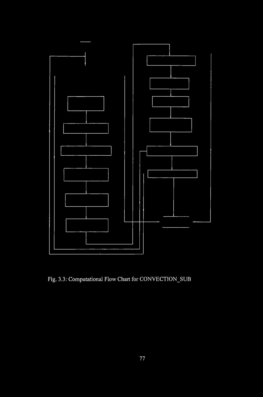
99 Fig. 3.3: Computational Flow Chart for CONVECTION_SUB 77


100 Fig. 3.4: Computational Flow Chart for FUELTEMPT_SUB 78


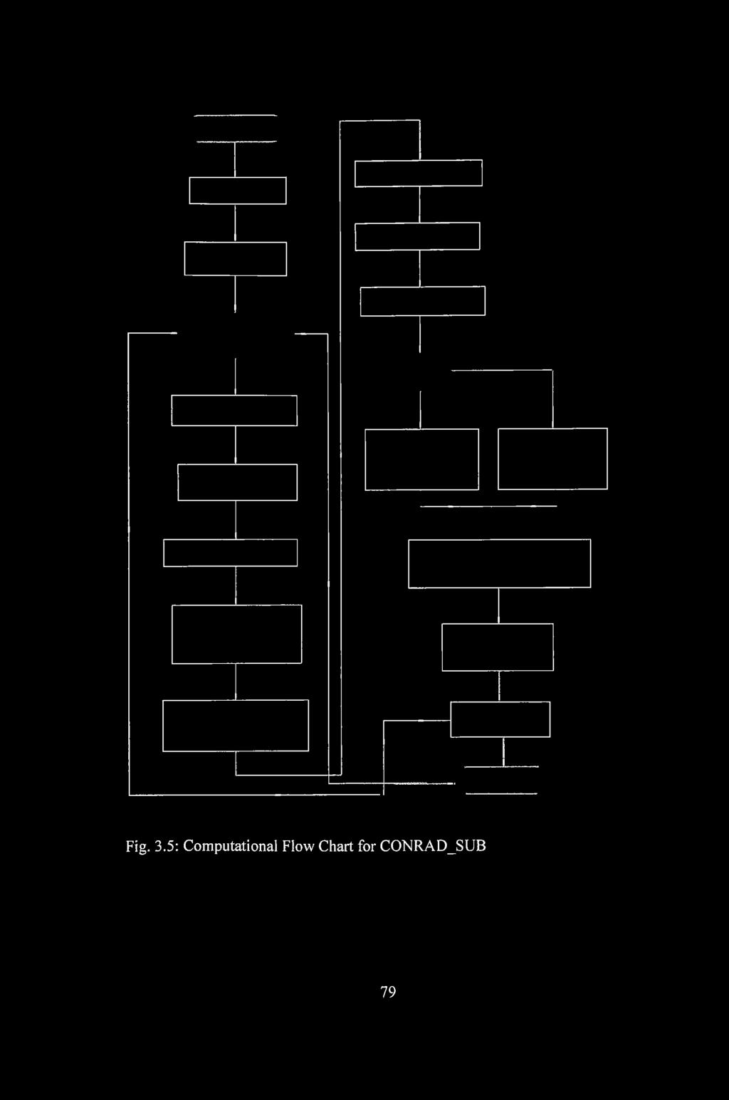
101 Fig. 3.5: Computational Flow Chart for CONRAD_SUB 79


102 Fig- 3.6: Computational Flow Chart for COMBINEDEFFECTS_SUB Fig. 3.7: Computational Flow Chart for COR FUELRATIO_SUB 80


103 Fig. 3.8: Computational Flow Chart for PRESSUREDROP_SUB 81
![3.4.1. INPUT DATA The input data to the code is given in the Table 3.1 [4] Table 3.1: Parameters used in the analyses.](/docs-images/86/94431091/images/104-0.jpg "PARAMETER VALUE Thermal Power (MWth /M W e) 250/120 Coolant Helium Helium inlet/outlet temperature 793/1173 (K) Helium pressure (MPa) 8.")


104 INPUT DATA The input data to the code is given in the Table 3.1 [4] Table 3.1: Parameters used in the analyses. PARAMETER VALUE Thermal Power (MWth /M W e) 250/120 Coolant Helium Helium inlet/outlet temperature 793/1173 (K) Helium pressure (MPa) 8.0 Helium mass flow rate (kg/s) 120 (100% full power) Core diameter (m) 3.5 Core height (m) 10.0 Fuel pebble diameter (m) 0.06 Porosity o f the bed PROGRAM SOLUTION AND IMPLEMENTATION ALGORITHM This subsection describes the sequence o f simulations performed and how the code solved the set o f analytical equations developed for the thermal analysis of the pebble bed nuclear reactor SIMULATION OF PRESSURE DROP ACROSS THE PEBBLE BED The pressure drop through friction across the pebble bed is an important phenomena that ultimately affects the heat transfer effectiveness. For different coolant mass flow rates, equation (3.12) and (3.17) were solved to determine the pressure drop and the pressure drop coefficient across the bed. 82

 was solved and the corresponding Reynolds number determined by varying the core diameter. 3.4.2.2 SIMULATION OF CONVECTIVE HEAT TRANSFER The temperature dependence of the convective heat transfer coefficient that follows from equation (3.")
105 The influence o f porosity on pressure drop was determined using equation (3.26) by varying the porosity between 0.0 and 1.0. The analysis was done for both laminar flow and turbulent flow. For the pebble bed nuclear reactor, the ratio of core diameter to fuel element diameter is very large. Thus, teken into account the dependence of porosity on core to fuel element diameter (D/d), simulation was performed to determine the effect o f the diameter ratio on pressure drop. Equation (3.27) was solved and the corresponding Reynolds number determined by varying the core diameter SIMULATION OF CONVECTIVE HEAT TRANSFER The temperature dependence of the convective heat transfer coefficient that follows from equation (3.35b) was simulated for different mass flow rates of the coolant. The code solved equation (3.47) and (3.48) and input the values into equation (3.44) and together with equation (3.43), the code solves equation (3.42). Finally, the convective heat transfer coefficient was evaluated from equation (3.35b). The calculations were done by varying the mass flow rate of the coolant at specified temperature(s) and secondly by varying the coolant temperature at specified coolant mass flow rate. To investigate the influence of porosity on convective heat transfer, equation (3.41) was solved by varying the porosity between 0.0 and
 the coolant temperature surrounding")
.")
106 SIMULATION OF TEMPERATURE PROFILE IN THE FUEL PEBBLE The simulation of the distribution of temperature in the fuel pebble was done with the assumption that (a) the coolant temperature surrounding the pebble was uniform and (b) the thermal power was generated within the fuelled region of the pebble. The maximum temperature within the pebble was at the centre of the pebble. Thus, by varying the pebble radius, the temperature distribution in the fuel pebble was obtained from equations (3.61, 3.77) SIMULATION OF EFFECTIVE THERMAL CONDUCTIVITY ACROSS THE PEBBLE BED CORE The effective radial heat conductivity of a core under normal operation conditions is necessary for the calculation of the mixing effect of hot gas streaks. For a specified gas temperature, pressure and coolant mass flow rate, equations (3.85, 3.89, 3.92, 3.93 and 3.95 to 3.98) were solved by varying the core radius or the gas temperature. The simulation was performed by first assuming that the contribution to the effective radial heat conductivity was only from the heat flux through the gap between neighbouring spheres due to heat conduction and radiation. The next assumption was that the contribution to the effective radial heat conductivity was only from the heat conducted and radiated through the fluid and solid phase from layer to layer. The overall effective radial heat conductivity was analysed by taken into account the effects o f the two assumptions above. 84


107 3.5 SUMMARY The mathematical formulation of the model and the set of equations for the prediction of the related phenomena have been presented. In formulating the model, the effect of porosity on heat transfer as well as pressure drop was considered and accounted for. A simulation code called PEBTAN written in FORTRAN 95 has been developed to analyse, predict and evaluate the thermal response of the pebble bed nuclear reactor. The code was carefully developed to simulate and analyse various conditions and scenarios including the convection heat transfer, distribution of temperature in a fuel pebble, effective radial heat conductivity distribution across the pebble bed core and the pressure drop through friction in the pebble bed. In the next chapter results obtained from the simulation experiments have been presented and discussed. Results are presented in the form o f graphs. 85


108 C H A PTER FO U R R ESULTS AND D ISCUSSIO N The chapter discusses the results obtained from the simulation experiments. The results are presented graphically. 4.1 PR ESSU R E DROP The pressure drop profile across the pebble bed is shown in Figs 4.1, 4.2, and 4.3. Increase in coolant flow rate reduces the fluid friction between the pebble surface and the fluid, induced as a result o f the fluid viscosity. The pressure drop coefficient consequently reduces with increased coolant flow rate as can be seen in Fig 4.1. by solving equation (3.17). (3.17) 86


109 The pressure drop created by the resistance to flow in the pebble bed can be varied by varying the coolant mass flow rate as all other parameters are fixed either by the reactor geometry or coolant choice. Fig. 4.2 shows the pressure drop model (eqn. 3.12) across the bed which increases with increasing Reynolds number (which is a direct function o f coolant mass flow rate). Fig. 4.2: Pressure drop profile for different core height. Equation (3.12) The flow o f coolant causes pressure drop which should not be too high (not exceeding 2% o f the system pressure) since high pressure drop across the bed requires high pumping power to pump the coolant. The coolant mass flow rate is however limited by both the minimum and maximum allowable temperatures in the core. The results indicate a very low pressure drop which means that there is considerable reduction of leakage or bypass flow and that the bulk o f the helium coolant flows through the voids between the fuel pebbles in the core and extract 87


110 the heat from the fuel. Further observation from the graph shows that the pressure drop increases with increasing core height. The effect o f core diameter to fuel element diameter on pressure drop was simulated based on equations (3.27 to 3.29) and the result is plotted in Fig From the plot it can be observed that smaller D/d ratio result in h ig h er Re and Re larger D/d ratio result in lower. 1-s, Re 1 ~ g. Fig. 4.3: Limiting curve of the diameter ratio as a function of modified Reynolds number. Furthermore from equations 3.28 and 3.29, for larger D/d ratio, the pressure drop coefficient y/, increases thus increasing the pressure drop. On the other hand, for smaller D/d ratio, the pressure drop coefficient y/t decreases thus decreasing the pressure drop. The effect is that with larger D/d ratio and the corresponding higher pressure drop over the core, higher coolant mass flow rate has to be transferred to the core and this requires more pumping power per coolant flow.


, the heat transfer rate seems to be independent o f Reynolds number.")
111 4.2 C O NVECTIVE H EAT TR A N SFER The heat transfer profile is shown in Fig. 4.4 by solving the system o f equations 3.45, 3.47 and Referring to equation (3.30), it is observed that to influence the heat transfer, either the convective heat transfer coefficient is increased or the heated surface area is increased or the temperature difference between the pebble surface and the bulk coolant is increased. Fig. 4.4: Convective heat transfer for pebble bed at Pr = 0.7 and e = 0.39 From the graph, the heat transfer increases with increasing Reynolds number which is a function o f mass rate o f flow, meaning, an increase in the mass rate o f flow enables the coolant to transfer more heat from the core. For low Reynolds number (i.e. Re < 100), the heat transfer rate seems to be independent o f Reynolds number. The quantity o f heat that the coolant can transfer from the core depends on the coolant inlet temperature and pressure. The magnitude o f the heat 89


112 transfer coefficient affect the heat transfer process and is influenced by a number o f parameters such as the geometry, the coolant flow rate and temperature, the flow condition and the fluid type. Figures 4.5 and 4.6 show the temperature dependence o f the convective heat transfer coefficient for different mass flow rates that follow s from the solution to the set o f equations 3.35b, 3.45, 3.47 and Fig. 4.5: Mass flow rate dependence o f heat transfer coefficient. From the graphs, the heat transfer coefficient increases with increasing temperature and coolant mass rate o f flow. From the expression, T^rf = Tg -+ p, increasing the convective heat transfer coefficient brings the fluid and the pebble surface temperature closer to each other which may frustrate the heat transfer. 90


. From the plot, it is observed that the temperature difference increases from the centre to the surface o f the fuel pebble.")
113 Fig. 4.6: Temperature dependence o f heat transfer coefficient. Again from the graphs o f Figs. 4.5 and 4.6, the convective heat transfer coefficient increases uniformly with increasing coolant temperature and mass rate o f flow which means that there is appreciable temperature difference between the fluid temperature and the pebble surface temperature. The heat transfer process is therefore improved. 4.3 TEM PER A TU R E PROFILE IN TH E FU EL PEBBLE The distribution o f temperature in a fuel pebble, Fig. 4.7, was obtained by solving equations (3.61 and 3.77). From the plot, it is observed that the temperature difference increases from the centre to the surface o f the fuel pebble. The larger temperature change in the fuel zone o f the pebble as compared with a smaller temperature change in the graphite zone is due to the coolant temperature surrounding the fuel pebble. 91


114 Fig. 4.7: Temperature profile in a fuel pebble The conditions that determine the fuel temperature in the pebble are the surface temperature o f the pebble and the power generated by a pebble. For all transients with a sustained helium flow, the hottest surface temperatures are found at the bottom o f the core since coolant flow from the top o f the core to the bottom. 4.4 EFFECTIVE RADIAL TH ERM AL CONDUCTIVITY The result o f the effective radial thermal conductivity distribution across the pebble bed core based on equation (3.90, and 3.92 to 3.98) is plotted in Fig The plot shows almost constant effective heat conductivity for all the three scenarios simulated. Observation from the graph indicates that the contribution to the overall effective thermal conductivity is largely as a result o f the heat conducted and radiated through the fluid and solid phase from layer to layer with the heat flux through the 92


 was observed as shown in Fig. 4.")
115 gap between neighbouring spheres due to heat conduction and radiation contributing less. This observation is as a result o f large contact surfaces between the pebbles as compared with the gaps between pebbles. 16 fe 14 5 I ^ ii 10 overall fluid and solid phase through gap betw een spheres Core Radius (mj Fig. 4.8: Effective radial conductivity distribution across the pebble bed. The strong temperature dependence o f the effective thermal conductivity o f the pebble bed (eqn. 3.90, and 3.92 to 3.98) was observed as shown in Fig Fig. 4.9: Effective thermal conductivity o f the pebble bed in helium. 93
, the gas pressure and the bed packing fraction have significant impact on the thermal conductivity of the")


116 The effective thermal conductivity o f pebble bed is influenced by many parameters with varying degrees. Parameters such as the thermal conductivity of the fuelled pebbles and the gas (helium), the gas pressure and the bed packing fraction have significant impact on the thermal conductivity of the pebble bed. To adequately account for the gas conductivity and pressure effect on the effective thermal conductivity, the thermal conductivity of the gas was modeled by expressing the gas conductivity in terms o f the gas pressure and temperature. Other parameters such as the pebble size and surface roughness have less impact on the thermal conductivity of the pebble bed. 4.5 EFFEC TS OF PO ROSITY ON H EAT TRANSFER AND PRESSURE DROP The porosity o f the pebble bed is very important to the mechanisms of heat and mass transfer as well as flow and pressure drop of the coolant throughout the pebble bed. Figs and 4.11 show the effect o f porosity on convective heat transfer (for n = 0.6, i.e. 5 x l0 2 < R e < 1 0 4and n = 0, i.e. very low Reynolds number) and pressure drop (n = 1 for laminar flow and n = 0.1 for turbulent flow) that follows from equations (3.41 and 3.26) respectively. 94

 Fig. 4.")

117 Porosity Fig. 4.10: Effect o f porosity on heat transfer. Equation (3.41) Fig. 4.11: Effect o f porosity on pressure drop. Equation (3.26) 95


118 From the graphs, the magnitude of the effect of porosity on both convective heat transfer and pressure drop increases with increasing porosity. From Fig. 4.10, the effect of porosity on heat transfer is more pronounced for low Reynolds number where the flow rate is also low. The magnitude o f the effect is such that a positive variation o f porosity results in a negative variation o f heat 1 VIS 1 1 transfer by a factor o f for n = 0.6 and n = s The effect o f porosity on pressure drop as shown in Fig is high for laminar flow than that o f turbulent flow. In both flow regimes, a positive variation of porosity causes a negative relative variation o f pressure drop by a factor - for n = 1 and n = 0.1. l s The essential effects the porosity has on heat transfer and pressure drop can be observed from Figs and For instance at s = 0.39, an error o f 1% in s causes an error of 1.64% and 1.26% for heat transfer (for n = 0 and n = 0.6 respectively) and an error of 4.28% and 3.70% for pressure drop (for n = 1.0 and n = 0.1 respectively). From these results, one can conclude that the magnitude of the effect of porosity on pressure drop is more pronounced than the effect on heat transfer. 96


119 CHAPTER FIVE CONCLUSIO N AND REC O M M EN D A TIO NS 5.1 CONCLUSIO NS A simplified analytical model o f the pebble bed nuclear reactor heat transfer and loss o f pressure through friction have been developed to analyse the convective heat transfer, the temperature distribution in the fuel pebble, the conduction and radiation heat transfer, loss of pressure through friction in the pebble bed and the effect of porosity on heat transfer as well as pressure drop. The set of equations for the prediction of the related phenomena have been presented. The developed model has been implemented on a personal computer using FORTRAN 95 programming language. The code, PEBTAN, correctly calculates the convective heat transfer coefficient, the convective heat transfer, the temperature distribution in the fuel pebble, effective radial thermal conductivity, pressure drop, pressure drop coefficient and the effect of porosity on heat transfer as well as pressure drop. Results obtained from simulation experiments are well represented by experimental results as reported in [39, 40, 42], Various experimental and theoretical models have been performed with good correlation between experimental results and that predicted by the Zehner-Schluender correlation [39, 42]. Thus, the effective thermal conductivity of the pebble bed nuclear reactor is most reliably predicted by the models o f [39, 42], The pressure drop coefficient 97
![and hence the pressure drop can be correlated according to [39, 40, 42] over the entire Reynolds number range of interest.](/docs-images/86/94431091/images/120-1.jpg "The influence o f porosity and its distribution across the bed has been pointed out. In particular the influence of porosity on heat transfer and pressure drop is addressed.")

120 and hence the pressure drop can be correlated according to [39, 40, 42] over the entire Reynolds number range of interest. The influence o f porosity and its distribution across the bed has been pointed out. In particular the influence of porosity on heat transfer and pressure drop is addressed. The study provides understanding of the thermal-hydraulic analysis of the pebble bed high temperature gas cooled nuclear reactor. The model can serve as the basis for a more detailed three dimensional computational fluid dynamics analysis techniques. In particular the outcomes o f the present study are; 1. The increase in the convective heat transfer coefficient is uniform indicating that there is appreciable temperature difference between the fluid temperature and the pebble surface temperature thus making it possible to achieve high thermal efficiency (i.e. high heat transfer rate) 2. Effective radial heat conductivity is largely as a result o f heat conducted and radiated through the fluid and solid phase from layer to layer with the heat flux through the gap between neighbouring spheres due to heat conduction and radiation contributing less 3. The pressure drop is small which means that less pumping power is required and hence higher efficiency. The pressure drop should not be too high (not exceeding 2% of the system pressure). The smaller pressure drop indicates that leakage or bypass flow is less and therefore high proportion of the helium coolant flows through the paths defined by the voids between the heated fuel pebbles in the core to extract the heat from the 98


121 pebbles during normal operation. The temperature of the pebbles during normal operation is consequently reduced which will also lead to lower temperatures during loss o f forced cooling events. 4. The magnitude of the effect of porosity on pressure drop is higher than the effect o f porosity on heat transfer. 5. The model can adequately account for the heat transfer phenomena as well as loss of pressure through friction in the pebble bed type high temperature nuclear reactor. In other words, the model can reliably predict the thermal response o f the pebble bed nuclear reactor. 5.2 R ECOM M ENDATIO NS A more detailed study of the thermal-hydraulic behaviour o f the pebble bed nuclear reactor is proposed using thermo-hydraulic models such as computational fluid dynamics (CFD) technique. CFD is an excellent tool to solve heat transfer problems, as in pebble bed modular reactor, because it can solve the convection, conduction and thermal radiation heat transfer mechanisms in arbitrary geometries in as much detail as possible to see the effect of detail features on the expected temperatures and pressures. The CFD model is therefore strongly recommended due to the ability of the model to assess detailed thermodynamic behaviour of the reactor both in steady state and transients. This can be achieved by developing the governing equations 99

 is")
122 for the conservation of mass, momentum and energy for the fluid which can be solved either in 1-dimensional, 2-dimensional or 3-dimensional using finite difference, finite element or finite volume method. A detailed study o f the core neutronic model for the pebble bed modular reactor is also recommended. Neutronic codes such as VSOP, TINTE and MCNP are used for different types of analysis and for cross checking between codes. Also interfacing of core neutronic models with other systems (for example the reactor core thermal-hydraulic model, the power conversion unit model) is recommended for future study. 100
![R EFERENCES [1] Kyu-Hyun Han, Kyong-Won Seo, Dae-Hyun Hwang and Soon Heung Chang, Development of a thermal analysis code for gas cooled reactors with annular fuels., Nuclear Eng. Des.,Vol.](/docs-images/86/94431091/images/123-1.jpg "236, 2006, pp. 164-178. [2] Driscoll M. J.and Hejzlar P., Reactor physics challenges in GEN-IV reactor design. Nuclear Eng. Tech., Vol. 37, 2005, pp. 1-10 [3] Huda M. Q. and Obara T.")
![, Development and testing of analytical models for the pebble type HTRs., Annals of Nuclear Energy, Vol. 35, 2008, pp. 1994-2005 [4] Kadak A. C.](/docs-images/86/94431091/images/123-2.jpg ", A future for nuclear energy, pebble bed reactors, MIT, 2004, Massachusetts Institute o f Technology, U.S.A [5] Kadak A. C.")
123 R EFERENCES [1] Kyu-Hyun Han, Kyong-Won Seo, Dae-Hyun Hwang and Soon Heung Chang, Development of a thermal analysis code for gas cooled reactors with annular fuels., Nuclear Eng. Des.,Vol. 236, 2006, pp [2] Driscoll M. J.and Hejzlar P., Reactor physics challenges in GEN-IV reactor design. Nuclear Eng. Tech., Vol. 37, 2005, pp [3] Huda M. Q. and Obara T., Development and testing of analytical models for the pebble type HTRs., Annals of Nuclear Energy, Vol. 35, 2008, pp [4] Kadak A. C., A future for nuclear energy, pebble bed reactors, MIT, 2004, Massachusetts Institute o f Technology, U.S.A [5] Kadak A. C., High temperature gas cooled reactors, MIT, 2000, Massachusetts Institute o f Technology, U.S.A [6] Casper-Petten V. E., Dynamics of the pebble bed nuclear reactor in the direct brayton cycle., PhD. Thesis, Delft University o f Technology, 2000 [7] Hans D. Gougar, Abderrafi M. Ougouag and William K. Terry., Advanced core design and fuel management for pebble bed reactors., INEEL/EXT [8] Pieter J. Venter and Mark N. Mitchell., Integrated design approach o f the pebble bed modular reactor using models., Nuclear Eng. Des. Vol. 237, 2007, pp
![[9] Christian Charlier, Robert Fagerholm, John Slabber, and Joseph L. Shayi., Safeguarding the pebble bed modular reactor-a new challenge for the IAEA, 2007. [10] Richard R. Schultz et al.](/docs-images/86/94431091/images/124-1.jpg ", Next generation nuclear plant, Idaho National Laboratory, 2008, U.S.A [11] Lohnert G. and Reutler H., The modular HTR-a new design of high temperature pebble bed reactor., J. Br. Nucl. Energy Soc.")
![, Vol. 22, 1983, pp. 197 [12] Zuying Gao, and Lei Shi., Thermal hydraulic calculation of HTR-10 for initial and equilibrium core., Nuclear Eng. Des., Vol. 218, 2002, pp.51-64. [13] John Slabber.](/docs-images/86/94431091/images/124-2.jpg ", PBMR safety design approach., A technology roadmap for generation IV nuclear energy systems, DOE, U.S.A, 2002 [14] Scherer W., Gerwin H., Kindt T.and Patscher W.")
124 [9] Christian Charlier, Robert Fagerholm, John Slabber, and Joseph L. Shayi., Safeguarding the pebble bed modular reactor-a new challenge for the IAEA, [10] Richard R. Schultz et al., Next generation nuclear plant, Idaho National Laboratory, 2008, U.S.A [11] Lohnert G. and Reutler H., The modular HTR-a new design of high temperature pebble bed reactor., J. Br. Nucl. Energy Soc., Vol. 22, 1983, pp. 197 [12] Zuying Gao, and Lei Shi., Thermal hydraulic calculation of HTR-10 for initial and equilibrium core., Nuclear Eng. Des., Vol. 218, 2002, pp [13] John Slabber., PBMR safety design approach., A technology roadmap for generation IV nuclear energy systems, DOE, U.S.A, 2002 [14] Scherer W., Gerwin H., Kindt T.and Patscher W., Analysis of reactivity and temperature transient experiments at the AVR high temperature reactor., Nuclear Science and Engineering., Vol. 97, 1987, pp [15] Nickel H., HTR coated particles and fuel elements., Presentation at the HTR/RCS 2002 high temperature reactor school, Cadarache, France, 2002 [16] Marina D. Savkina., Probabilistic accident analysis of the pebble bed modular reactor for use with risk informed regulations. M.Sc. Thesis, Massachusetts Institute o f Technology (MIT), 2004, pp [ 17] (August 5, 2008) 102
![[18] Kadak A. C.,MIT pebble bed reactor project., Nuclear Science and Engineering Department, Massachusetts Institute of Technology, U.S.A, 2007 [19] Du Toit C. G., Rousseau P. G, Greyvenstein G. P. and Landman W.](/docs-images/86/94431091/images/125-1.jpg "A., A systems CFD model of a packed bed high temperature gas cooled nuclear reactor. International Journal o f thermal sciences, Vol. 45, 2006, pp.70-85. [20] Greyvenstein G. P. and Van Antwerpen H.")
 plant operator training simulator system., Nuclear Eng.")
125 [18] Kadak A. C.,MIT pebble bed reactor project., Nuclear Science and Engineering Department, Massachusetts Institute of Technology, U.S.A, 2007 [19] Du Toit C. G., Rousseau P. G, Greyvenstein G. P. and Landman W. A., A systems CFD model of a packed bed high temperature gas cooled nuclear reactor. International Journal o f thermal sciences, Vol. 45, 2006, pp [20] Greyvenstein G. P. and Van Antwerpen H. J., A finite volume based network method for the prediction of heat, mass and momentum transfer in a pebble bed reactor., 2nd International Topical Meeting on HTR technology, Beijin, China., Sept , [21] Dudley T., Bouwer W., De Villiers P., Wang Z., The thermal-hydraulic model for the pebble bed modular reactor (PBMR) plant operator training simulator system., Nuclear Eng. Des, 2008 [22] Hossain K., Buck M., Bensaid N., Bernnat W., Lohnert G., Development o f a fast 3D thermal-hydraulic tool for the design and safety studies for the HTRs., Nuclear Eng. Des., [23] Becker S.and Laurien E., Three-dimensional numerical simulation of flow and heat transport in high temperature nuclear reactors. Nuclear Eng. Des., Vol. 222, 2003, pp [24] Jan-Patrice S, Julien C, Brian M and Lewis L., 3-D simulation of the coupled convective, conductive and radiative heat transfer during decay heat removal in an HTR., Nuclear Eng. Des., Vol. 237, 2007, pp
![[25] Van der Merwe J., Van Antwerpen H. J.and Mulder E. J., Heat transfer correlation limitations at the pebble bed reflector interface.](/docs-images/86/94431091/images/126-1.jpg ", Proceedings HTR2006:3rd International Topical Meeting on HTR technology, Johannesburg, South Africa, Oct. 1-4, 2006 [26] Greyvenstein G. P., Van Antwerpen H. J.and Rousseau P. G., The systems CFD approach applied to a pebble bed reactor core.")
![, International journal o f nuclear energy science and technology, inaugural issue, 2004 [27] Martin P. Van Stadan., Analysis of the effectiveness of cavity cooling system.](/docs-images/86/94431091/images/126-2.jpg ", 2nd International Topical Meeting on HTR technology, Beijin, China, Sept. 22-24,2004 [28] Ayelet Walter, Alexander Schulz and Guenter Lohnert.")
126 [25] Van der Merwe J., Van Antwerpen H. J.and Mulder E. J., Heat transfer correlation limitations at the pebble bed reflector interface., Proceedings HTR2006:3rd International Topical Meeting on HTR technology, Johannesburg, South Africa, Oct. 1-4, 2006 [26] Greyvenstein G. P., Van Antwerpen H. J.and Rousseau P. G., The systems CFD approach applied to a pebble bed reactor core., International journal o f nuclear energy science and technology, inaugural issue, 2004 [27] Martin P. Van Stadan., Analysis of the effectiveness of cavity cooling system., 2nd International Topical Meeting on HTR technology, Beijin, China, Sept ,2004 [28] Ayelet Walter, Alexander Schulz and Guenter Lohnert., Comparison of two models for a pebble bed modular reactor core coupled to a Brayton cycle., Nuclear Eng. Des. Vol. 236, 2006, pp [29] Petersen K., The safety concepts of the HTRs with natural heat removal for the core in accidents., Juel-1872, [30] Breitbach G.and Barthels H., The radiant heat transfer in the high temperature reactor core after failure of the afterheat removal systems., Nuclear technology, Vol. 49, 1980, pp [31] Arcot R. B., David C. T. Pel., Heat transfer in gas-solid packed bed system-3. Overall heat transfer rates in adiabatic beds., Ind. Eng. Chem. Process Des. Dev., Vol. 18, 1979, pp
![[32] Du Toit C. G., The numerical determination of the variation in the porosity of the pebble bed core.](/docs-images/86/94431091/images/127-1.jpg ", School for Mechanical and Materials Engineering, Potchefstroom University for CHE, South Africa. [33] Du Toit C. G., Analysis of the radial variation in the porosity o f annular packed beds.")
![, Proceedings HTR2006: 3rd International Topical Meeting on HTR technology, Johannesburg, South Africa, Oct 1-4, 2006. [34] Du Toit C. G., Radial variation in porosity in annular packed beds.](/docs-images/86/94431091/images/127-2.jpg ", Nuclear Eng. Des., Vol. 238, 2008, pp. 3073-3079. [35] Motoo Fumizawa, Yoshihi Kaneto and Masanori Izumi.")
127 [32] Du Toit C. G., The numerical determination of the variation in the porosity of the pebble bed core., School for Mechanical and Materials Engineering, Potchefstroom University for CHE, South Africa. [33] Du Toit C. G., Analysis of the radial variation in the porosity o f annular packed beds., Proceedings HTR2006: 3rd International Topical Meeting on HTR technology, Johannesburg, South Africa, Oct 1-4, [34] Du Toit C. G., Radial variation in porosity in annular packed beds., Nuclear Eng. Des., Vol. 238, 2008, pp [35] Motoo Fumizawa, Yoshihi Kaneto and Masanori Izumi., Porosity effect in the core thermal hydraulics for ultra high temperature gas cooled reactor. [36] Vortmeter D.and Schuster J., Evaluation o f steady flow profiles in the rectangular and circular packed beds by a variational method., Chemical Eng. Sci., Vol. 38, pp [37] Goodling J. S., Vachon R. I., Stelpflug W. S.and Ying S. J., Radial porosity distribution in cylindrical beds packed with spheres., Power technology, Vol. 35, 1983, pp [38] Sederman A. J., Alexander P.and Gladden L. F., Structure of packed bed probed by magnetic resonance imaging., Power technology, Vol. 117, 2001, pp [39] Achenbach E. Helium cooled systems, HTR-pebble bed design, in Heat transfer and fluid flow in nuclear systems, edited by Henri Fenech, pp , Pergamon Press Inc.,, New York,
![[40] KTA standards, Reactor core design of High Temperature Gas-Cooled Reactors, Nuclear safety standards commission, KTA standards 3102.1 (1978), 3102.2 (1983), 3102.3 (1981).](/docs-images/86/94431091/images/128-1.jpg "[41] Haipeng Li, Xiaojin Huang, Liangju Zhang., A simplified mathematical dynamic model of the HTR-10 high temperature gas-cooled reactor with control system design purpose.")
128 [40] KTA standards, Reactor core design of High Temperature Gas-Cooled Reactors, Nuclear safety standards commission, KTA standards (1978), (1983), (1981). [41] Haipeng Li, Xiaojin Huang, Liangju Zhang., A simplified mathematical dynamic model of the HTR-10 high temperature gas-cooled reactor with control system design purpose., Annals of nuclear energy, Vol.35, 2008, pp [42] Achenbach E., Heat and fluid flow characteristics of packed beds., Experimental thermal and fluid science., Vol. 10, 1995, pp [43] William Frederik Geert Van Rooijen., Improving fuel cycle design and safety characteristics of a gas cooled fast reactor., IOS press, 2006, pp [44] Rousseau P. G. and Greyvenstein G. P., One dimensional reactor model for the integrated simulation o f the PBMR power plant. 106

:: Nut, Nus, Nu, Fe, HTCEFF, mu, mve, nt, kl, dpt, dnul REAL (KIND=3):: dp, n, ev, MDRe,")
,PARAMETER::SYHEAD='(9(2X,A30,4(A8,A30)))'")
129 APPENDIX A THE PEBTA N CODE FOR TH ERM AL ANALYSIS OF TH E PEBBLE BED H IG H TEM PERATURE GAS COOLED REACTO R. PROGRAM MAINFINAL IMPLICIT NONE REAL, PARAMETER :: PI = , d = 0.06, Pr = 0.7, Pe = 30 REAL, PARAMETER :: q = 5.77E-8, Er = 0.88, Ys = 50, HTC = 230 REAL (K IN D =3):: Tg, Re, e, mv, A, H, Dc, DNV, PRS REAL (KIND=3) :: TCOG, Nur, B, M l, N l, Ygap, Yfs, Kr, rhgap, rhfs, rhov, Rc, Nul REAL (K IN D =3):: Nut, Nus, Nu, Fe, HTCEFF, mu, mve, nt, kl, dpt, dnul REAL (KIND=3):: dp, n, ev, MDRe, PDCEFF, PDROP, DENSTY, m, Xt, Dv, CTFED, MDREt, k, dnu REAL (KIND=3) :: DTI, DTII, QP, TCD, QC, CPD, DTc, Rfz, Rpeb, Tgv, PW, Tin, Tout, Tgcd, Reff INTEGER :: Tgc, mvc, SWITCH CHARACTER(LEN=*),PARAMETER::SYHEAD='(9(2X,A30,4(A8,A30)))' CHARACTER(LEN=*),PARAMETER::SYDATA='(9(6X,F30.4,4(A8,F30.4)))' 107
 WRITE(21,SYHEAD)'MASS FLOW RATE',',','HEAT TRANSFER COEFFICIENT' OPEN(22,FILE='MNHTRATIOOUT.")
 WRITE(23,SYHEAD) GAS TEMPERATURE, HEAT TRANSFER COEFFICIENT OPEN (24, FILE-M NFUELPROFLOUT.")
130 OPEN(21,FILE -M NHTCEFFOUT.csv', FORM = 'FORMATTED', ACCESS = 'SEQUENTIAL', & ACTION = 'READWRITE', STATUS = 'REPLACE') WRITE(21,SYHEAD)'MASS FLOW RATE',',','HEAT TRANSFER COEFFICIENT' OPEN(22,FILE='MNHTRATIOOUT.csv', FORM = 'FORMATTED', ACCESS-SEQ UEN TIAL', & ACTION = 'READ WRITE', STATUS = 'REPLACE') WRITE(22,SYHEAD)'REYNOLDS NO,',', 'NUSSELT NO.' OPEN(23,FILE = 'MNTEMPTOUT.csv', FORM = 'FORMATTED', ACCESS = 'SEQUENTIAL', & ACTION = 'READWRITE', STATUS = REPLACE ) WRITE(23,SYHEAD) GAS TEMPERATURE, HEAT TRANSFER COEFFICIENT OPEN (24, FILE-M NFUELPROFLOUT.csv, FORM = FORMATTED', ACCESS = 'SEQUENTIAL', ACTION = READ W RITE, STATUS = REPLACE ) WRITE (24,SYHEAD) PEBBLE RADIUS,,, 'FUEL TEMPT,',', SHELL TEMPT,,', 'COOLANT TEMPT OPEN(25,FILE = MNCONRADOUT.csv', FORM = FORMATTED', ACCESS= 'SEQUENTIAL, ACTION = READWRITE, STATUS = REPLACE ) WRITE(25,SYHEAD) CORE RADIUS,',', 'HEAT FLUX-GAP(r)',',, HEAT FLUX-SOLID(r),,', HEAT FLUX- OVERALL(r) OPEN (27, FILE = 'MNCBNEFFOUT.csv, FORM = FORMATTED, ACCESS= SEQUENTIAL, ACTION = READWRITE, STATUS = 'REPLACE') WRITE (27,SYHEAD)'POROSITY',',','EFFECTS ON PRSS DROP/HEAT TRNF' 108

 WRITE (31,SYHEAD)'REYNOLDS NUMBER',',','PRESSURE DROP' OPEN (32,FILE = 'MNCNRDReffOUT.")
131 OPEN (28, FILE = 'MNDIAMRATIOOUT.csv', FORM = 'FORMATTED', ACCESS = 'SEQUENTIAL', ACTION = 'READ WRITE1, STATUS = 'REPLACE') W RITE (28,SYHEAD)'MODIFIED REY NO.',',','CORE FUEL DIAM' OPEN (29, FILE = 'MNCOEFFOUT.csV, FORM = 'FORMATTED', ACCESS = 'SEQUENTIAL', ACTION = READWRITE', STATUS = 'REPLACE') WRITE (29,SYHEAD)'MODIFIED RE NUMBER',,','PRESSURE COEFFICIENT' OPEN (31, FILE = 'MNCOMPAROUT.csv', FORM = 'FORMATTED', ACCESS = 'SEQUENTIAL', ACTION = 'READWRITE', STATUS = 'REPLACE') WRITE (31,SYHEAD)'REYNOLDS NUMBER',',','PRESSURE DROP' OPEN (32,FILE = 'MNCNRDReffOUT.csv', FORM = 'FORMATTED', ACCESS = 'SEQUENTIAL', ACTION = READWRITE', STATUS = 'REPLACE') W RITE(32,SYHEAD)'TEMPERATURE',',', 'EFFECTIVE CONDUCTIVITY' OPEN (51,FILE = 'SPHTCEFFOUT.csv', FORM = 'FORMATTED', ACCESS = SEQUENTIAL', & ACTION = READWRITE, STATUS = REPLACE ) WRITE (51,SYHEAD) MASS FLOW RATE,',', HEAT TRANSFER COEFFICIENT' OPEN (52, FILE = SPHTRATIOOUT.csv', FORM = 'FORMATTED', ACCESS = SEQUENTIAL', ACTION = 'READWRITE', STATUS = 'REPLACE') WRITE (52,SYHEAD)'REYNOLDS NO.',',', 'NUSSELT NO.' OPEN (53,FILE = 'SPTEMPTOUT.csv', FORM = FORMATTED, ACCESS = SEQUENTIAL, & ACTION = READWRITE, STATUS = 'REPLACE') WRITE(53,SYHEAD) GAS TEMPERATURE,,,'HEAT TRANSFER COEFFICIENT' 109
 WRITE (54,SYHEAD) 'PEBBLE RADIUS',',','FUEL TEMPT',',','SHELL TEMPT',',','COOLANT TEMPT' OPEN (55, FILE =")
 WRITE(55,SYHEAD)'CORE RADIUS',',', HEAT FLUX-GAP(r)',',, 'HEAT FLUX-SOLID(r)',',, 'HEAT FLUX-0VERALL(r) OPEN")
132 OPEN (54, FILE = 'SPFUELPROFLOUT.csv', FORM = FORMATTED', ACCESS = 'SEQUENTIAL', ACTION = 'READ WRITE', STATUS = 'REPLACE') WRITE (54,SYHEAD) 'PEBBLE RADIUS',',','FUEL TEMPT',',','SHELL TEMPT',',','COOLANT TEMPT' OPEN (55, FILE = 'SPCONRADOUT.csv', FORM = 'FORMATTED', ACCESS = 'SEQUENTIAL', ACTION = 'READWRITE', STATUS = 'REPLACE') WRITE(55,SYHEAD)'CORE RADIUS',',', HEAT FLUX-GAP(r)',',, 'HEAT FLUX-SOLID(r)',',, 'HEAT FLUX-0VERALL(r) OPEN (57, FILE = SPCBNEFFOUT.csv', FORM = 'FORMATTED', ACCESS = SEQUENTIAL, ACTION = READWRITE, STATUS = REPLACE ) WRITE (57,SYHEAD)'POROSITY',V, EFFECTS ON PRSS DROP/HEAT TRNF' OPEN (58, FILE = SPDIAMRATIOOUT.csv, FORM = FORMATTED, ACCESS = SEQUENTIAL, ACTION = READWRITE, STATUS = REPLACE ) WRITE (58,SYHEAD) MODIFIED REY NO.,',, CORE FUEL DIAM OPEN (59, FILE = SPCOEFFOUT.csv, FORM = 'FORMATTED', ACCESS = 'SEQUENTIAL', & ACTION = 'READWRITE', STATUS = 'REPLACE') WRITE (59,SYHEAD)'MODIFIED RE NUMBER',',', PRESSURE COEFFICIENT' OPEN (61, FILE = 'SPCOMPAROUT.csv', FORM = 'FORMATTED', ACCESS = 'SEQUENTIAL', ACTION = 'READWRITE', STATUS = 'REPLACE') WRITE (61,SYHEAD)'REYNOLDS NUMBER',',','PRESSURE DROP' 110
 WRITE (62,SYHEAD)'TEMPERATURE',',',")
\" READ *, SWITCH WRITE (*,*) WRITE (*,*) GO TO (10,")
.")
133 OPEN (62,FILE = 'SPCNRDReffOUT.csv', FORM = 'FORMATTED', ACCESS = 'SEQUENTIAL', &ACTION = 'READWRITE', STATUS = 'REPLACE') WRITE (62,SYHEAD)'TEMPERATURE',',', 'EFFECTIVE CONDUCTIVITY' WRITE (*,*) WRITE (*,*) READ INSTRUCTIONS CAREFULLY WRITE (*,*) 50 PRINT *,"INPUT:SWITCH(enter 1-MAIN, 2-CONV, 3-FUELTEMPT, 4- CONRAD, 5-POROSITY, 6-RATIO, 7-DROP, 8 TO END PROGRAM)" READ *, SWITCH WRITE (*,*) WRITE (*,*) GO TO (10, 20, 30, 40, 60, 70, 80, 100) SWITCH 100 stop 20 WRITE (*,*) WRITE (*,*)'THIS SECTION ANALYSE THE CONVECTION HEAT TRANSFER ONLY' WRITE (*,*)...' WRITE (*,*) PRINT*, "INPUT: Dc = CORE DIAMETER" READ*, Dc PRINT*, "INPUT: e = POROSITY OF BED" READ*, e PRINT*, "INPUT: H = HEIGHT OF BED" READ*, H PRINT*, "INPUT: PRS = READ*, PRS DO Tgc = 600,1400,200 HELIUM PRESSURE" 111
*(Tgc**0.71)*(l-2.0E-4*PRS) DNV = 3.674E-7*(Tgc**0.7) RE = ((mv/a)*d)/dnv Nul = 0.664*((RE/e)**(l/2))*(Pr**(l/3)) Nut = (0.037*((RE/e)**0.")
*((Pr**(2/3))-l)) Nus = 2+(sqrt((Nul**2)+(Nut**2))) Nu = Fe*Nus HTCEFF = (Nu*TCOG)/d W RITE(51,SYDATA)mv,7, HTCEFF WRITE(52,SYDATA)RE,',',NU mv = mv + 0.")
*(Dc/2)*((Dc/2) + H) Fe = 1.0+1.5*(1 -e ) TCOG = 2.682E-3*(l + 1.123E-3*PRS)*(Tgv**0.71)*(l-2.0E-4*PRS) DNV = 3.674E-7*(Tgv**0.")
134 PRINT*, "INPUT: mv = HELIUM MASS FLOW RATE" READ*, mv DO WHILE (mv <= 150) A = 2*(PI)*(Dc/2)*((Dc/2) + H) Fe = 1,0 +1.5*(1 -e) TCOG = 2.682E-3*(l E-3*PRS)*(Tgc**0.71)*(l-2.0E-4*PRS) DNV = 3.674E-7*(Tgc**0.7) RE = ((mv/a)*d)/dnv Nul = 0.664*((RE/e)**(l/2))*(Pr**(l/3)) Nut = (0.037*((RE/e)**0.8)*Pr)/(l+2.443*((RE/e)**0.1)*((Pr**(2/3))-l)) Nus = 2+(sqrt((Nul**2)+(Nut**2))) Nu = Fe*Nus HTCEFF = (Nu*TCOG)/d W RITE(51,SYDATA)mv,7, HTCEFF WRITE(52,SYDATA)RE,',',NU mv = mv END DO END DO DO mvc = 60,120,20 PRINT*, "INPUT: Tgv = GAS TEPMERATURE (VARYING FROM IN STEPS OF 10)" READ*, Tgv DO WHILE (Tgv <= 1400) A = 2*(PI)*(Dc/2)*((Dc/2) + H) Fe = *(1 -e ) TCOG = 2.682E-3*(l E-3*PRS)*(Tgv**0.71)*(l-2.0E-4*PRS) DNV = 3.674E-7*(Tgv**0.7) RE = ((mvc/a)*d)/dnv Nul = 0.664*((RE/e)**(l/2))*(Pr**(l/3)) Nut = (0.037*((RE/e)**0.8)*Pr)/(l+2.443*((RE/e)**0.1)*((Pr**(2/3))-l)) Nus = 2+(sqrt((Nul**2)+(Nut**2))) 112
 CLOSE(53, STATUS = 'KEEP') WRITE (*,*) WRITE (*,*) END OF THIS SECTION.")
 WRITE (*,*) GO TO 50 30 WRITE (*,*) WRITE (*,*) 'THIS SECTION ANALYSE THE TEMPERATURE PROFILE")
 PRINT*, 'INPUT: PW = THERMAL POWER OF THE REACTOR (\"250MW FULL POWER\", \"125MW HALF POWER\", \"62.")
135 Nu = Fe*Nus HTCEFF = (Nu*TCOG)/d WRITE(53,SYDATA)Tgv,',',HTCEFF Tgv = Tgv + 10 END DO END DO CLOSE(51, STATUS = 'KEEP') CLOSE(52, STATUS = KEEP') CLOSE(53, STATUS = 'KEEP') WRITE (*,*) WRITE (*,*) END OF THIS SECTION. CHOOSE ANOTHER SECTION OR END PROGRAM. READ INSTRUCTION' WRITE (*,*) WRITE (*,*) GO TO WRITE (*,*) WRITE (*,*) 'THIS SECTION ANALYSE THE TEMPERATURE PROFILE IN A FUEL PEBBLE ONLY' WRITE (*,*)'... ' WRITE (*,*) PRINT*, 'INPUT: PW = THERMAL POWER OF THE REACTOR ("250MW FULL POWER", "125MW HALF POWER", "62.5MW QUATER POWER") READ*, PW PRINT*, 'INPUT: Tin = INLET GAS TEMPERATURE' READ*, Tin PRINT*, INPUT: Tout = OUTLET GAS TEMPERATURE' READ*, Tout PRINT*, 'INPUT: H = CORE HEIGHT' READ*, H PRINT*, 'INPUT: Dc = CORE DIAMETER' 113
 Rc = Dc/2.0 CPD = PW/(PI*(Rc**2.0)*H) IF (Rpeb <= 0.025)THEN Rfz = Rpeb ELSE IF (Rpeb > 0.025) THEN Rfz = 0.")
) W RITE(54,SYDATA)Rpeb,',',DTI,DTII,',',DTc Rpeb = Rpeb + 0.0001 END DO CLOSE(54,STATUS = 'KEEP') WRITE (*,*) WRITE (*,*)'END OF THIS SECTION.")
136 READ*, Dc PRINT*, 'INPUT: e = POROSITY OF THE BED (0.36,< e <0.42)' READ*, e Rpeb = DO WHILE (Rpeb <= 0.03) Tg = (Tin + Tout)/2.0 TCD = (((2.549E-4*Tg)+l,5 )/l. 163)*(4.1868E3/3600) Rc = Dc/2.0 CPD = PW/(PI*(Rc**2.0)*H) IF (Rpeb <= 0.025)THEN Rfz = Rpeb ELSE IF (Rpeb > 0.025) THEN Rfz = END IF QC = (CPD/(l-e))*((Rpeb/Rfz)**3) Qp = (4/3)*Qc*PI*(Rfz**3) DTI = -(Qp/(8*TCD*PI*Rfz)) DTII = -((Qp/(4*PI*TCD))*((1/Rfz) - (1/Rpeb))) DTc = Qp/(4 * PI * HTC *(Rpeb** 2)) W RITE(54,SYDATA)Rpeb,',',DTI,DTII,',',DTc Rpeb = Rpeb END DO CLOSE(54,STATUS = 'KEEP') WRITE (*,*) WRITE (*,*)'END OF THIS SECTION. CHOOSE ANOTHER SECTION OR END PROGRAM. READ INSTRUCTION' WRITE (*,*) WRITE (*,*) GO TO
 PRINT *, \"INPUT: Dc = CORE RADIUS\" READ *, Dc PRINT *, \"INPUT: PRS = HELIUM PRESSURE\" READ *, PRS PRINT *, \"INPUT: Tin = INLET GAS")
) Tg = (Tin + Tout)/2.0 Kr = 8*(2-(l-(2*(d/(2*Rc))))**2) TCOG = 2.")
) Nur = ((4*q*(Tg**3))/((2/Er) - l))*(d/tcog) Ygap = 1 + e*nur rhgap = ((Pe/Kr) + ((1 - SQRT(1 - e))*ygap))*tcog B = 1,25*((1 - e)/e)**l.")
137 40 WRITE (*,*) WRITE (*,*) 'THIS SECTION ANALYSE THE CONDUCTION/RADIATION HEAT TRANSFER ONLY1 WRITE (*,*)'...' WRITE (*,*) PRINT *, "INPUT: Dc = CORE RADIUS" READ *, Dc PRINT *, "INPUT: PRS = HELIUM PRESSURE" READ *, PRS PRINT *, "INPUT: Tin = INLET GAS TEMPERATURE" READ *, Tin PRINT *, "INPUT: Tout = OUTLET GAS TEMPERATURE" READ *, Tout PRINT *, "INPUT: e = POROSITY OF BED" READ *, e PRINT *, "INPUT: Tgcd = VARIABLE GAS TEMPERATURE" READ *, Tgcd Rc = 0.04 DO WHILE (Rc <= (Dc/2)) Tg = (Tin + Tout)/2.0 Kr = 8*(2-(l-(2*(d/(2*Rc))))**2) TCOG = 2.682E-3*( E-3*PRS)*(Tg**0.71)*(1.0 - (2.0E-4*PRS)) Nur = ((4*q*(Tg**3))/((2/Er) - l))*(d/tcog) Ygap = 1 + e*nur rhgap = ((Pe/Kr) + ((1 - SQRT(1 - e))*ygap))*tcog B = 1,25*((1 - e)/e)**l.l M l = B*(TCOG/Ys) N1 = 1 + (Nur*(TCOG/Ys)) IF (Ml == N 1) THEN Yfs = (1/((B-1)*M1))*(((2/3*M1)*((B**3)-1)/(B-1))-((B+I)*(l-Nur))) ELSE IF (M l.ne.nl)then 115
)*ygap)) + ((SQRT(1 - e))*yfs))*tcog WRITE(55,SYDATA)Rc,V,rHgap,',',rHfs,',',rHOV Rc = Rc + 0.")
) Nur = ((4*q*(Tgcd**3))/((2/Er) - l))*(d/tcog) Ygap = 1 + e*nur B = 1.25*((1 - e)/e)**l.")
THEN Yfs = (2/(N-M))*((((B*N-M)/((N-M)**2))*LOG(N/M))-((B-l)/(N- M))+(((B+1)/(2*M))*(N-M-1))) Reff = (((Pe/Kr) + ((1 - SQRT(1 - e))*ygap)) + ((SQRT(1 - e))*yfs))*tcog")
138 Yfs=(2/(N 1 -M 1 ))*((((B *N 1-M 1)/((N 1-M1)**2))*L0G(N1/M1 ))-((B-1)/(N 1 - M 1 ))+(((B+1)/(2*M 1))*(N1-M1-1))) rhfs = ((Pe/Kr) + ((SQRT(l-e))*Yfs))*TCOG rhov = (((Pe/Kr) + ((1 - SQRT(1 - e))*ygap)) + ((SQRT(1 - e))*yfs))*tcog WRITE(55,SYDATA)Rc,V,rHgap,',',rHfs,',',rHOV Rc = Rc END IF END DO DO WHILE (Tgcd <= 1400) K r= 8*(2-(l-(2*(d/(Dc))))**2) TCOG = 2.682E-3*( E-3*PRS)*(Tgcd**0.71)*(l.0 - (2.0E-4*PRS)) Nur = ((4*q*(Tgcd**3))/((2/Er) - l))*(d/tcog) Ygap = 1 + e*nur B = 1.25*((1 - e)/e)**l.l M = B*(TCOG/Ys) N = 1 + (Nur*(TCOG/Y s)) IF (M = N) THEN Yfs = (l/((b-l)*m ))*(((2/3*M )*((B**3)-l)/(B-l))-((B+l)*(l-N ur))) ELSE IF (M.NE.N)THEN Yfs = (2/(N-M))*((((B*N-M)/((N-M)**2))*LOG(N/M))-((B-l)/(N- M))+(((B+1)/(2*M))*(N-M-1))) Reff = (((Pe/Kr) + ((1 - SQRT(1 - e))*ygap)) + ((SQRT(1 - e))*yfs))*tcog WRITE(62,SYDATA)Tgcd,',',Reff Tgcd = Tgcd END IF END DO CLOSE(55, STATUS = 'KEEP') CLOSE(62, STATUS = 'KEEP') WRITE (*,*) WRITE (*,*) END OF THIS SECTION. CHOOSE ANOTHER SECTION OR END PROGRAM. READ INSTRUCTION 116
.")
\" READ *, n PRINT *, \"INPUT: k = FOR HIGH HIGH REYNOLDS NUMBER (k=0.")
\" READ *, nt PRINT *, \"INPUT: kl = FOR LOW REYNOLDS NUMBER (k = 0 )\" READ *, kl DO WHILE (ev<= 1.")
139 WRITE (*,*) WRITE (*,*) GO TO WRITE (*,*) WRITE (*,*)THIS SECTION ANALYSE THE INFLUENCE OF POROSITY ON HEAT TRANSFER & PRESSURE DROP ONLY' WRITE (*,*)... ' WRITE ( V ) PRINT *, "INPUT: ev = THE VARIATION OF POROSITY OF THE BED" READ *, ev PRINT *, "INPUT: n = FOR LAMINAR FLOW (n=l)" READ *, n PRINT *, "INPUT: k = FOR HIGH HIGH REYNOLDS NUMBER (k=0.6)" READ *, k PRINT *, "INPUT: nt = FOR TURBULENT FLOW (n=0.1)" READ *, nt PRINT *, "INPUT: kl = FOR LOW REYNOLDS NUMBER (k = 0 )" READ *, kl DO WHILE (ev<= 1.0) dp = (3-ev*(2-n))/(l-ev) dpt = (3-ev*(2-nt))/(l-ev) IF (ev >= 1)THEN WRITE (*,*) END IF dnu = (1 - k*ev)/(l - ev) dnul = (l-kl* ev)/(l-ev) IF (ev >= 1)THEN WRITE (*,*) END IF W RITE(57,SYDATA)ev,7,dP,7,dPt,7, dnu,',, dnul 117

'.")

140 ev = ev END DO CLOSE(57, STATUS = 'KEEP') WRITE (*,*) WRITE (*,*) END OF THIS SECTION. CHOOSE ANOTHER SECTION OR END PROGRAM. READ INSTRUCTION' WRITE (*,*) WRITE (*,*) GO TO WRITE ( V ) WRITE (*,*) THIS SECTION ANALYSE THE CORE TO FUEL ELEMENT DIAMETER RATIO ONLY' WRITE (*,*)'...' WRITE (*,*) PRINT * "INPUT: Tin = INLET GAS TEMPERATURE" READ *, Tin PRINT *, "INPUT: Tout = OUTLET GAS TEMPERATURE" READ *, Tout PRINT *, "INPUT: H = THE CORE HEIGHT" READ *, H PRINT * "INPUT: m = THE HELIUM MASS FLOW RATE" READ *, m PRINT * "INPUT: Dv = VARIABLE CORE DIAMETER (>=0.15)" READ *, Dv CTFED = Dv/d DO WHILE (CTFED <= 58) Tg = (Tin + Tout)/2.0 A = 2*(Pi)*(Dv/2)*((Dv/2) + H) DNV = (3.674E-7*(Tg**0.7)) Re = ((m/a)*d)/dnv 118
 WRITE (*,*) WRITE (*,*)'END OF THIS SECTION.")
 WRITE (*,*) GO TO 50 80 WRITE(*,*) WRITE (*,*)'THIS SECTION ANALYSE THE PRESSURE DROP")
 PRINT *, \"INPUT: Dc = CORE DIAMETER\" READ *, Dc PRINT *, \"INPUT: PRS = HELIUM PRESSURE\" READ *, PRS")
141 Xt = (0.78/(CTFED**2)) MDREt - Re/( I -Xt) WRITE(58,SYDATA) MDREtCTFED Dv = Dv CTFED = Dv/d ND DO CLOSE(58,STATUS = 'KEEP') WRITE (*,*) WRITE (*,*)'END OF THIS SECTION. CHOOSE ANOTHER SECTION OR END PROGRAM. READ INSTRUCTION' WRITE (*,*) WRITE (*,*) GO TO WRITE(*,*) WRITE (*,*)'THIS SECTION ANALYSE THE PRESSURE DROP THROUGH THE CORE ONLY' WRITE (*,*)'...' WRITE (*,*) PRINT *, "INPUT: Dc = CORE DIAMETER" READ *, Dc PRINT *, "INPUT: PRS = HELIUM PRESSURE" READ *, PRS PRINT *, "INPUT Tin = INLET TEMPERATURE OF GAS" READ *, Tin PRINT *, "INPUT Tout - OUTLET TEMPERATURE OF GAS" READ *, Tout PRINT *, "INPUT e = POROSITY OF THE BED" READ *, e PRINT *, "INPUT: mve = HELIUM MASS FLOW RATE" READ *, mve 119
*((l+(0.446*(PRS/(Tg**1.2))))**(-1.0)) DNV= (3.674E-7*(Tg**0.")
) WRITE(59,SYDATA)MDRe,',',PDCEFF PDROP = PDCEFF*(H/d)*((l-e)/(e**3.")
 CLOSE(61, STATUS = 'KEEP') WRITE (*,*) WRITE (*,*)'END OF THIS SECTION.")
142 PRINT *, "INPUT: H = CORE HEIGHT" READ *, H DO WHILE (mve <= 150) Tg = (Tin + Tout)/2.0 A = 2*(Pi)*(Dc/2)*((Dc/2) + H) DENSTY = 48.14*(PRS/Tg)*((l+(0.446*(PRS/(Tg**1.2))))**(-1.0)) DNV= (3.674E-7*(Tg**0.7)) Re = ((mve/a)*d)/dnv MDRe = Re/(l-e) PDCEFF = (320/MDRe) + (6/(MDRe**0.1)) WRITE(59,SYDATA)MDRe,',',PDCEFF PDROP = PDCEFF*(H/d)*((l-e)/(e**3.0))*(l/(2*DENSTY))*((mve/A)**2) W RITE(61,S YD ATA)Re,',',PDROP mve = mve END DO CLOSE(59, STATUS = 'KEEP') CLOSE(61, STATUS = 'KEEP') WRITE (*,*) WRITE (*,*)'END OF THIS SECTION. CHOOSE ANOTHER SECTION OR END PROGRAM. READ INSTRUCTION' WRITE (*,*) WRITE (*,*) GO TO WRITE (*,*) WRITE (*,*) 'THIS SECTION COMBINES ALL THE SEPERATE MODULES' WRITE (*,*)... ' WRITE (*,*) PRINT*, "INPUT: Tin = INLET GAS TEMPERATURE" READ*, Tin PRINT*, "INPUT: Tout = OUTLET GAS TEMPERATURE" 120
\" READ*, PW PRINT*, \"INPUT: e = POROSITY OF THE BED (0.36<e<0.")
\" READ *, k PRINT *, \"INPUT: nt = FOR TURBULENT FLOW (n=0.")
143 READ*, Tout PRINT*, "INPUT: PRS = HELIUM PRESSURE" READ*, PRS PRINT*, "INPUT: PW = THERMAL POWER OF THE REACTOR ('250MW FULL POWER, '125MW HALF POWER', '62.5MW QUATER POWER )" READ*, PW PRINT*, "INPUT: e = POROSITY OF THE BED (0.36<e<0.42)" READ*, e PRINT*, "INPUT: H = HEIGHT OF BED (FIXED)" READ*, H PRINT*, "INPUT: Dc = CORE DIAMETER" READ*, Dc PRINT *, "INPUT: n = FOR LAMINAR OR TURBULENT ( n = l)" READ*, n PRINT *, "INPUT: k = FOR HIGH HIGH REYNOLDS NUMBER(k = 0.6)" READ *, k PRINT *, "INPUT: nt = FOR TURBULENT FLOW (n=0.1)" READ *, nt PRINT *, "INPUT: kl = FOR LOW REYNOLDS NUMBER (k = 0 )" READ *, kl PRINT *, "INPUT: ev = THE VARIATION OF POROSITY OF THE BED" READ *, ev PRINT *, "INPUT: m = HELIUM MASS FLOW RATE (FIXED)" READ *, m PRINT *, "INPUT: Dv = VARIATION OF CORE DIAMETER" READ *, Dv PRINT *, "INPUT: mu = mve VARIATION OF MASS FLOW RATE" READ *, mu PRINT *, "INPUT: Tgcd READ *, Tgcd = VARIABLE GAS TEMPERATURE" 121
 CALLCONRAD_SUB (Tg,TCOG,Nur,B,Ml,Nl,e,Ygap,Yfs,Kr,rHgap,rHfs,rHOV,Dc,Rc,PRS,Tin,Tout, Tgcd,")
 W RITE(21,SYDATA)mv,',',HTCEFF WRITE(22,SYDATA)RE,',',NU")
ev,V,dP,V,dPt,',',dNu,dNul WRITE(28,S YD AT A)MDREt,',',CTFED WRITE(29,SYDATA)MDRe, PDCEFF WRITE(31,SYDATA)Re,',',PDROP")
144 CALLCONVECTIONSUB (Re,Nul,Nut,Nus,Fe,Nu,TCOG,DNV,A,H,e,PRS,mv,Dc,HTCEFF,Tgv,Tgc,mve) CALLFUELTEMPT_SUB (e,dc,h,tg,dti,dtii,qp,tcd,qc,cpd,rc,dtc,rfz,rpeb,tin,tout) CALLCONRAD_SUB (Tg,TCOG,Nur,B,Ml,Nl,e,Ygap,Yfs,Kr,rHgap,rHfs,rHOV,Dc,Rc,PRS,Tin,Tout, Tgcd, Reff) CALL COMBINEDEFFECTS_SUB (dp, n, ev, dnu, k, nt, kl, dpt, dnul) CALL COREFUELRATIOJSUB (Tg, A, DNV, Xt, Dv, CTFED, MDREt, Re, m, H,Tin,Tout) CALL PRESSUREDROP SUB (PDROP, PDCEFF, Re, DENSTY, DNV, A, e, Tg, MDRe, PRS, mu, Dc, H,Tin,Tout) W RITE(21,SYDATA)mv,',',HTCEFF WRITE(22,SYDATA)RE,',',NU WRITE(23,SYDATA)Tgv,V,HTCEFF WRITE(24,SYDATA)Rpeb,',',DTI,V,DTII,V,DTc WRITE(25,SYDATA)Rc,V,rHgap,V,rHfs,V,rHOV W RITE(27,SYDATA)ev,V,dP,V,dPt,',',dNu,dNul WRITE(28,S YD AT A)MDREt,',',CTFED WRITE(29,SYDATA)MDRe, PDCEFF WRITE(31,SYDATA)Re,',',PDROP WRITE(32,SYDATA)Tgcd,',',Reff CLOSE(21, STATUS = 'KEEP') CLOSE(22, STATUS = 'KEEP') CLOSE(23, STATUS = KEEP') 122
 CL0SE(31, STATUS = 'KEEP') CLOSE(32, STATUS = 'KEEP') WRITE (*,*) WRITE (*,*) 'END OF")
")
 A =")
145 CLOSE(24, STATUS = 'KEEP') CLOSE(25, STATUS = 'KEEP') CLOSE(27, STATUS = 'KEEP') CLOSE(28, STATUS = KEEP') CLOSE(29, STATUS = 'KEEP') CL0SE(31, STATUS = 'KEEP') CLOSE(32, STATUS = 'KEEP') WRITE (*,*) WRITE (*,*) 'END OF THIS SECTION. CHOOSE ANOTHER SECTION OR END PROGRAM. READ INSTRUCTION WRITE (*,*) WRITE (*,*) GO TO 50 CONTAINS!! SUBROUTINES SUBROUTINE CONVECTION_SUB(Re,Nul,Nut,Nus,Fe,Nu,TCOG,DNV,A,H,e,PRS,mv,Dc,H TCEFF,Tgv, Tgc,mvc) IMPLICIT NONE REAL(KIND=3) :: Tgv,Re,Nul,Nut,Nus,Fe,Nu,TCOG,DNV,A,H,e,PRS,mv,Dc,HTCEFF INTEGER :: Tgc, mve DO Tgc = 600,1400,200 PRINT*, "INPUT: mv = HELIUM MASS FLOW RATE" READ*, mv DO WHILE (mv <= 150) A = 2*(PI)*(Dc/2)*((Dc/2) + H) 123
**(l/2))*(Pr**(l/3)) Nut = (0.037*((Re/e)**0.8)*Pr)/(l+2.443*((Re/e)**0.")
\" READ*, Tgv DO WHILE (Tgv <= 1400) A =")
 Re = ((mvc/a)*d)/dnv Nul = 0.")
146 Fe = *(1 -e ) TCOG = 2.682E-3 *( E-3*PRS)*(Tge**0.71)*(1-2.0E-4*PRS) DNV = 3.674E-7*(Tgc**0.7) Re - ((mv/a)*d)/dnv Nul = 0.664*((Re/e)**(l/2))*(Pr**(l/3)) Nut = (0.037*((Re/e)**0.8)*Pr)/(l+2.443*((Re/e)**0.1)*((Pr**(2/3))-l)) Nus = 2+(sqrt((Nul**2)+(Nut**2))) Nu Fe*Nus HTCEFF = (Nu*TCOG)/d W RITE(21,SYDATA)mv,',',HTCEFF WRITE(22,SYDATA)RE,',',NU mv = mv END DO END DO DO mve 60,120,20 PRINT*, "INPUT: Tgv = GAS TEPMERATURE (VARYING FROM IN STEPS OF 10)" READ*, Tgv DO WHILE (Tgv <= 1400) A = 2*(PI)*(De/2)*((De/2) + H) Fe = *(1 - e) TCOG = 2.682E-3 *( E-3*PRS)*(Tgv* *0.71 )*( 1-2.0E-4*PRS) DNV = 3.674E-7*(Tgv**0.7) Re = ((mvc/a)*d)/dnv Nul = 0.664*((Re/e)**(l/2))*(Pr**(l/3)) Nut = (0.037*((Re/e)**0.8)*Pr)/(l+2.443*((Re/e)**0.1)*((Pr**(2/3))-l)) Nus = 2+(sqrt((Nul**2)+(Nut**2))) Nu = Fe*Nus HTCEFF = (Nu*TCOG)/d WRITE(23,SYDATA)Tgv,V,HTCEFF Tgv = Tgv
 IMPLICIT NONE REAL(KIND=3) :: DTI, Qp,")
 Tg = (Tin + Tout)/2 TCD = (((2.549E-4*Tg)+l.5 )/l. 163)*(4.")
)*((rpeb/rfz)**3) Qp = (4/3)*QC*PI*(Rfz**3) DTI = -(Qp/(8*TCD*PI*Rfz)) DTII =")
147 END DO END DO RETURN END SUBROUTINE CONVECTION SUB SUBROUTINE FUELTEMPT_SUB(e,Dc,H,Tg,DTI,DTII,QP,TCD,QC,CPD,Rc,DTc,Rfz,Rpeb,T in,tout) IMPLICIT NONE REAL(KIND=3) :: DTI, Qp, TCD, QC, CPD, Rc, DTII, DTc,Rfz, Rpeb, e, Dc, H, Tg, Tin, Tout Rpeb = DO WHILE (Rpeb <= 0.03) Tg = (Tin + Tout)/2 TCD = (((2.549E-4*Tg)+l.5 )/l. 163)*(4.1868E3/3600) Rc = Dc/2 CPD = PW/(PI*(Rc**2)*H) IF (Rpeb <= 0.025)THEN Rfz = Rpeb ELSE IF (Rpeb > 0.025) THEN Rfz = END IF QC = (CPD/( 1 -e))*((rpeb/rfz)**3) Qp = (4/3)*QC*PI*(Rfz**3) DTI = -(Qp/(8*TCD*PI*Rfz)) DTII = -((Qp/(4*PI*TCD))*((1/Rfz) - (1/Rpeb))) DTc = Qp/(4*PI*HTC*(Rpeb**2)) WRITE(24,SYDATA)Rpeb,',',DTI,',',DTII,',',DTc Rpeb = Rpeb
 ::Tg,TCOG,Nur,B,Ml,Nl,e,Ygap,Yfs,Kr,rHgap,rHfs,rHOV,Dc, Rc,PRS,Tin, Tout,Tgcd,Reff Rc = 0.")
) Nur = ((4*q*(Tg**3))/((2/Er) - l))*(d/tcog) Ygap = 1 + e*nur rhgap = ((Pe/Kr) + ((1 - SQRT(1 - e))*ygap))*tcog B = 1.25*((1 - e)/e)**l.")
then Yfs=(2/(N1-M1))*((((B*N1-Ml)/((N1-M1)**2))*L0G(N1/Ml))-((B-1)/(N1- M 1))+(((B+1 )/(2*M 1 ))*(N 1 -M 1-1))) rhfs = ((Pe/Kr) + ((SQRT(l-e)):i!")
148 END DO RETURN END SUBROUTINE FUELTEMPT_SUB SUBROUTINE CONRAD_SUB(T g,tcog,nur,b,m 1,N 1,e, Y gap,y fs,kr,rhgap,rhfs,rhov,dc, Rc,PRS,Tin,Tout,Tgcd, Reff) IMPLICIT NONE REAL(KIND=3) ::Tg,TCOG,Nur,B,Ml,Nl,e,Ygap,Yfs,Kr,rHgap,rHfs,rHOV,Dc, Rc,PRS,Tin, Tout,Tgcd,Reff Rc = 0.04 DO WHILE (Rc <= (Dc/2)) Tg = (Tin + Tout)/2.0 Kr = 8*(2 - (1-2 *(d/(2 * Rc))) ** 2) TCOG = 2.682E-3*( E-3*PRS)*(Tg**0.71)*(1.0 - (2.0E-4*PRS)) Nur = ((4*q*(Tg**3))/((2/Er) - l))*(d/tcog) Ygap = 1 + e*nur rhgap = ((Pe/Kr) + ((1 - SQRT(1 - e))*ygap))*tcog B = 1.25*((1 - e)/e)**l.l M l = B*(TCOG/Ys) N1 = 1 + (Nur*(TCOG/Ys)) IF (Ml = =N 1) THEN Yfs = (1/((B-1)*M1))*(((2/3*M1)*((B**3)-1)/(B-1))-((B+I)*(l-Nur))) ELSE IF (M l.ne.nl)then Yfs=(2/(N1-M1))*((((B*N1-Ml)/((N1-M1)**2))*L0G(N1/Ml))-((B-1)/(N1- M 1))+(((B+1 )/(2*M 1 ))*(N 1 -M 1-1))) rhfs = ((Pe/Kr) + ((SQRT(l-e)):i!Yfs))*TCOG rhov = (((Pe/Kr) + ((1 - SQRT(1 - e))*ygap)) + ((SQRT(1 - e))*yfs))*tcog 126
*(Tgcd**0.71)*(1.0 - (2.0E-4*PRS)) Nur = ((4*q*(Tgcd**3))/((2/Er) - l))*(d/tcog) Ygap = 1 + e*nur B = 1.")
 N = 1 + (Nur*(TCOG/Y s)) IF (M = N) THEN Yfs = (l/((b-l)*m ))*(((2/3*M )*((B**3)-l)/(B-l))-((B+l)*(l-N ur))) ELSE IF (M.NE.")
)*yfs))*tcog WRITE(32,SYDATA)Tgcd,',',Reff Tgcd = Tgcd + 10.")
149 WRITE(25,SYDATA)Rc,',',rHgap,7,rHfs,7,rHOV Rc = Rc END IF END DO DO WHILE (Tgcd <= 1400) Kr = 8*(2-(l-(2*(d/(Dc))))**2) TCOG = 2.682E-3*( E-3*PRS)*(Tgcd**0.71)*(1.0 - (2.0E-4*PRS)) Nur = ((4*q*(Tgcd**3))/((2/Er) - l))*(d/tcog) Ygap = 1 + e*nur B = 1.25*((1 - e)/e)**l.l M = B*(TCOG/Ys) N = 1 + (Nur*(TCOG/Y s)) IF (M = N) THEN Yfs = (l/((b-l)*m ))*(((2/3*M )*((B**3)-l)/(B-l))-((B+l)*(l-N ur))) ELSE IF (M.NE.N)THEN Yfs=(2/(N-M))*((((B*N-M)/((N-M)**2))*LOG(N/M))-((B-l)/(N- M))+(((B+1 )/(2*M))*(N-M-1))) Reff = (((Pe/Kr) + ((1 - SQRT(1 - e))*ygap)) + ((SQRT(1 - e))*yfs))*tcog WRITE(32,SYDATA)Tgcd,',',Reff Tgcd = Tgcd END IF END DO RETURN END SUBROUTINE CONRAD SUB SUBROUTINE COMBINEDEFFECTS_SUB(dP, n, ev, dnu, k, nt, kl, dpt, dnul) IMPLICIT NONE REAL(KIND=3) :: dp, n, ev, dnu, k,nt, kl, dpt, dnul DO WHILE (ev <= 1.0) 127
ev,',',dP,V,dPt,V,dNu,V,dNul ev = ev + 0.")
 Tg = (Tin + Tout)/2.0 A = 2*(Pi)*(Dv/2)*((Dv/2) + H) DNV = (3.674E-7*(Tg**0.")
150 dp = (3-ev*(2-n))/(l-ev) dpt = (3-ev*(2-nt))/(l-ev) IF (ev >= 1)THEN WRITE (*,*) END IF dnu = (1 - k*ev)/(l - ev) dnul = (l-kl* ev)/(l-ev) IF (ev >= 1)THEN WRITE (*,*) END IF WRITE(27,SYDATA)ev,',',dP,V,dPt,V,dNu,V,dNul ev = ev END DO RETURN END SUBROUTINE COMBINEDEFFECTS SUB SUBROUTINE COREFUELRATIO SUB (Tg, A, DNV, Xt, Dv, CTFED, MDREt, Re, m, H, Tin, Tout) IMPLICIT NONE REAL(KIND=3):: Tg, A, DNV, Xt, Dv, CTFED, MDREt, Re, m, H, Tin, Tout CTFED = Dv/d DO WHILE (CTFED <= 58) Tg = (Tin + Tout)/2.0 A = 2*(Pi)*(Dv/2)*((Dv/2) + H) DNV = (3.674E-7*(Tg**0.7)) Re = ((m/a)*d)/dnv Xt = (0.78/(CTFED**2)) MDREt = Re/(l-Xt) W RITE(28,SYDATA)MDREt,',',CTFED 128

 Tg = (Tin + Tout)/2.0 A = 2*(PI)*(Dc/2)*((Dc/2) + H) DENSTY = 48.")
) Re = ((mu/a)*d)/dnv MDRe = Re/(l-e) PDCEFF = (320/MDRe) + (6/(MDRe**0.")
151 Dv = Dv CTFED = Dv/d END DO RETURN END SUBROUTINE COREFUELRATIO SUB SUBROUTINE PRESSUREDROPSUB (PDROP, PDCEFF, Re, DENSTY, DNV, A, e, Tg, MDRe, PRS, mu, Dc, H, Tin, Tout) IMPLICIT NONE REAL(KIND=3):: PDROP, PDCEFF, Re, DENSTY, DNV, A, e, Tg, MDRe, PRS, mu, Dc, H, Tin, Tout DO WHILE (mu <= 150.0) Tg = (Tin + Tout)/2.0 A = 2*(PI)*(Dc/2)*((Dc/2) + H) DENSTY = 48.14*(PRS/Tg)*((l+(0.446*(PRS/(Tg**1.2))))**(-1.0)) DNV= (3.674E-7*(Tg**0.7)) Re = ((mu/a)*d)/dnv MDRe = Re/(l-e) PDCEFF = (320/MDRe) + (6/(MDRe**0.1)) WRITE(29,SYDATA)MDRe,',',PDCEFF PDROP = PDCEFF*(H/d)*((l-e)/(e**3.0))*(l/(2*DENSTY))*((mu/A)**2) WRITE(31,SYDATA)Re,',',PDROP mu = mu END DO RETURN END SUBROUTINE PRESSUREDROP_SUB END PROGRAM MAINFINAL 129
Coolant Flow and Heat Transfer in PBMR Core With CFD
 Heikki Suikkanen GEN4FIN 3.10.2008 1/ 27 Coolant Flow and Heat Transfer in PBMR Core With CFD Heikki Suikkanen Lappeenranta University of Technology Department of Energy and Environmental Technology GEN4FIN
A FINITE VOLUME-BASED NETWORK METHOD FOR THE PREDICTION OF HEAT, MASS AND MOMENTUM TRANSFER IN A PEBBLE BED REACTOR
 A FINITE VOLUME-BASED NETWORK METHOD FOR THE PREDICTION OF HEAT, MASS AND MOMENTUM TRANSFER IN A PEBBLE BED REACTOR GP Greyvenstein and HJ van Antwerpen Energy Systems Research North-West University, Private
Effect of Fuel Particles Size Variations on Multiplication Factor in Pebble-Bed Nuclear Reactor
 International Conference Nuclear Energy for New Europe 2005 Bled, Slovenia, September 5-8, 2005 Effect of Fuel Particles Size Variations on Multiplication Factor in Pebble-Bed Nuclear Reactor Luka Snoj,
Pebble flow in a High Temperature Reactor
 Pebble flow in a High Temperature Reactor Andrea Ooms Physics of Nuclear Reactors TU Delft PNR-131-2008-003 May 15, 2008 Preface This thesis represents my graduation work for the Master in Applied Physics
United States Nuclear Regulatory Commission US-NRC, USA
 TRISO-coated particle fuel phenomenon identification and ranking tables (PIRTS) for fission product transport due to manufacturing, operations and accidents S.D. Rubin United States Nuclear Regulatory
EFFECT OF DISTRIBUTION OF VOLUMETRIC HEAT GENERATION ON MODERATOR TEMPERATURE DISTRIBUTION
 EFFECT OF DISTRIBUTION OF VOLUMETRIC HEAT GENERATION ON MODERATOR TEMPERATURE DISTRIBUTION A. K. Kansal, P. Suryanarayana, N. K. Maheshwari Reactor Engineering Division, Bhabha Atomic Research Centre,
Neutronic Issues and Ways to Resolve Them. P.A. Fomichenko National Research Center Kurchatov Institute Yu.P. Sukharev JSC Afrikantov OKBM,
 GT-MHR Project High-Temperature Reactor Neutronic Issues and Ways to Resolve Them P.A. Fomichenko National Research Center Kurchatov Institute Yu.P. Sukharev JSC Afrikantov OKBM, GT-MHR PROJECT MISSION
Lesson 14: Reactivity Variations and Control
 Lesson 14: Reactivity Variations and Control Reactivity Variations External, Internal Short-term Variations Reactivity Feedbacks Reactivity Coefficients and Safety Medium-term Variations Xe 135 Poisoning
Lectures on Applied Reactor Technology and Nuclear Power Safety. Lecture No 6
 Lectures on Nuclear Power Safety Lecture No 6 Title: Introduction to Thermal-Hydraulic Analysis of Nuclear Reactor Cores Department of Energy Technology KTH Spring 2005 Slide No 1 Outline of the Lecture
Kr-85m activity as burnup measurement indicator in a pebble bed reactor based on ORIGEN2.1 Computer Simulation
 Journal of Physics: Conference Series PAPER OPEN ACCESS Kr-85m activity as burnup measurement indicator in a pebble bed reactor based on ORIGEN2.1 Computer Simulation To cite this article: I Husnayani
OECD/NEA Transient Benchmark Analysis with PARCS - THERMIX
 OECD/NEA Transient Benchmark Analysis with PARCS - THERMIX Volkan Seker Thomas J. Downar OECD/NEA PBMR Workshop Paris, France June 16, 2005 Introduction Motivation of the benchmark Code-to-code comparisons.
Lectures on Applied Reactor Technology and Nuclear Power Safety. Lecture No 5. Title: Reactor Kinetics and Reactor Operation
 Lectures on Nuclear Power Safety Lecture No 5 Title: Reactor Kinetics and Reactor Operation Department of Energy Technology KTH Spring 2005 Slide No 1 Outline of the Lecture (1) Reactor Kinetics Reactor
12 Moderator And Moderator System
 12 Moderator And Moderator System 12.1 Introduction Nuclear fuel produces heat by fission. In the fission process, fissile atoms split after absorbing slow neutrons. This releases fast neutrons and generates
USA HTR NEUTRONIC CHARACTERIZATION OF THE SAFARI-1 MATERIAL TESTING REACTOR
 Proceedings of HTR2008 4 th International Topical Meeting on High Temperature Reactors September 28-October 1, 2008, Washington, D.C, USA HTR2008-58155 NEUTRONIC CHARACTERIZATION OF THE SAFARI-1 MATERIAL
CANDU Safety #3 - Nuclear Safety Characteristics Dr. V.G. Snell Director Safety & Licensing
 CANDU Safety #3 - Nuclear Safety Characteristics Dr. V.G. Snell Director Safety & Licensing 24/05/01 CANDU Safety - #3 - Nuclear Safety Characteristics.ppt Rev. 0 vgs 1 What Makes A Safe Nuclear Design?
HIGH TEMPERATURE THERMAL HYDRAULICS MODELING
 HIGH TEMPERATURE THERMAL HYDRAULICS MODELING OF A MOLTEN SALT: APPLICATION TO A MOLTEN SALT FAST REACTOR (MSFR) P. R. Rubiolo, V. Ghetta, J. Giraud, M. Tano Retamales CNRS/IN2P3/LPSC - Grenoble Workshop
SUB-CHAPTER D.1. SUMMARY DESCRIPTION
 PAGE : 1 / 12 CHAPTER D. REACTOR AND CORE SUB-CHAPTER D.1. SUMMARY DESCRIPTION Chapter D describes the nuclear, hydraulic and thermal characteristics of the reactor, the proposals made at the present stage
Chem 481 Lecture Material 4/22/09
 Chem 481 Lecture Material 4/22/09 Nuclear Reactors Poisons The neutron population in an operating reactor is controlled by the use of poisons in the form of control rods. A poison is any substance that
Reactivity Coefficients
 Reactivity Coefficients B. Rouben McMaster University Course EP 4D03/6D03 Nuclear Reactor Analysis (Reactor Physics) 2015 Sept.-Dec. 2015 September 1 Reactivity Changes In studying kinetics, we have seen
PRISMATIC MODULAR REACTOR ANALYSIS WITH MELCOR. A Thesis NI ZHEN
 PRISMATIC MODULAR REACTOR ANALYSIS WITH MELCOR A Thesis by NI ZHEN Submitted to the Office of Graduate Studies of Texas A&M University in partial fulfillment of the requirements for the degree of MASTER
Introduction to Reactivity and Reactor Control
 Introduction to Reactivity and Reactor Control Larry Foulke Adjunct Professor Director of Nuclear Education Outreach University of Pittsburgh IAEA Workshop on Desktop Simulation October 2011 Learning Objectives
Hybrid Low-Power Research Reactor with Separable Core Concept
 Hybrid Low-Power Research Reactor with Separable Core Concept S.T. Hong *, I.C.Lim, S.Y.Oh, S.B.Yum, D.H.Kim Korea Atomic Energy Research Institute (KAERI) 111, Daedeok-daero 989 beon-gil, Yuseong-gu,
Study on the improved recuperator design used in the direct helium-turbine power conversion cycle of HTR-10
 Study on the improved recuperator design used in the direct helium-turbine power conversion cycle of HTR-10 Wu Xinxin 1), Xu Zhao ) 1) Professor, INET, Tsinghua University, Beijing, P.R.China (xinxin@mail.tsinghua.edu.cn)
VHTR Thermal Fluids: Issues and Phenomena
 VHTR Thermal Fluids: Issues and Phenomena www.inl.gov Technical workshop at PHYSOR 2012: Advanced Reactor Concepts April 15, 2012 Knoxville, TN Gerhard Strydom Idaho National Laboratory (INL) Overview
AN OVERVIEW OF NUCLEAR ENERGY. Prof. Mushtaq Ahmad, MS, PhD, MIT, USA
 AN OVERVIEW OF NUCLEAR ENERGY Prof. Mushtaq Ahmad, MS, PhD, MIT, USA Outline of the Seminar 2 Motivation and Importance of Nuclear Energy Future Energy Planning in the Kingdom Current Status of Nuclear
The influence of thorium on the temperature reactivity. coefficient in a 400 MWth pebble bed high temperature. plutonium incinerator reactor
 The influence of thorium on the temperature reactivity coefficient in a 400 MWth pebble bed high temperature plutonium incinerator reactor G. A. Richards Project-based mini-dissertation (Option C) for
INTRODUCTION TO CATALYTIC COMBUSTION
 INTRODUCTION TO CATALYTIC COMBUSTION R.E. Hayes Professor of Chemical Engineering Department of Chemical and Materials Engineering University of Alberta, Canada and S.T. Kolaczkowski Professor of Chemical
If there is convective heat transfer from outer surface to fluid maintained at T W.
 Heat Transfer 1. What are the different modes of heat transfer? Explain with examples. 2. State Fourier s Law of heat conduction? Write some of their applications. 3. State the effect of variation of temperature
DEVELOPMENT OF MELCOR INPUT TECHNIQUES FOR HIGH TEMPERATURE GAS-COOLED REACTOR ANALYSIS. A Thesis JAMES ROBERT CORSON, JR.
 DEVELOPMENT OF MELCOR INPUT TECHNIQUES FOR HIGH TEMPERATURE GAS-COOLED REACTOR ANALYSIS A Thesis by JAMES ROBERT CORSON, JR. Submitted to the Office of Graduate Studies of Texas A&M University in partial
Journal of NUCLEAR SCIENCE and TECHNOLOGY, Vol. 41, No. 7, p (July 2004)
") Journal of NUCLEAR SCIENCE and TECHNOLOGY, Vol. 41, No. 7, p. 765 770 (July 2004) TECHNICAL REPORT Experimental and Operational Verification of the HTR-10 Once-Through Steam Generator (SG) Heat-transfer
Journal of NUCLEAR SCIENCE and TECHNOLOGY, Vol. 41, No. 7, p. 765 770 (July 2004) TECHNICAL REPORT Experimental and Operational Verification of the HTR-10 Once-Through Steam Generator (SG) Heat-transfer
Modeling and analysis of a depressurized loss of forced cooling event in a thorium fueled high temperature reactor
 Department Radiation Science & Technology Section Nuclear Energy and Radiation Applications Faculty of Applied Sciences Delft University of Technology Mekelweg 15, 2629 JB Delft The Netherlands Modeling
The moderator temperature coefficient MTC is defined as the change in reactivity per degree change in moderator temperature.
 Moderator Temperature Coefficient MTC 1 Moderator Temperature Coefficient The moderator temperature coefficient MTC is defined as the change in reactivity per degree change in moderator temperature. α
THE USE OF PB-BI EUTECTIC AS THE COOLANT OF AN ACCELERATOR DRIVEN SYSTEM. Joint research Centre of the European Commission Ispra, Italy.
 THE USE OF PB-BI EUTECTIC AS THE COOLANT OF AN ACCELERATOR DRIVEN SYSTEM Alberto Peña 1, Fernando Legarda 1, Harmut Wider 2, Johan Karlsson 2 1 University of the Basque Country Nuclear Engineering and
20.1 Xenon Production Xe-135 is produced directly in only 0.3% of all U-235 fissions. The following example is typical:
 20 Xenon: A Fission Product Poison Many fission products absorb neutrons. Most absorption cross-sections are small and are not important in short-term operation. Xenon- has a cross-section of approximately
ULOF Accident Analysis for 300 MWt Pb-Bi Coolled MOX Fuelled SPINNOR Reactor
 ULOF Accident Analysis for 300 MWt Pb-Bi Coolled MOX Fuelled SPINNOR Reactor Ade afar Abdullah Electrical Engineering Department, Faculty of Technology and Vocational Education Indonesia University of
HEAT TRANSFER CAPABILITY OF A THERMOSYPHON HEAT TRANSPORT DEVICE WITH EXPERIMENTAL AND CFD STUDIES
 HEAT TRANSFER CAPABILITY OF A THERMOSYPHON HEAT TRANSPORT DEVICE WITH EXPERIMENTAL AND CFD STUDIES B.M. Lingade a*, Elizabeth Raju b, A Borgohain a, N.K. Maheshwari a, P.K.Vijayan a a Reactor Engineering
APPLICATION OF THE COUPLED THREE DIMENSIONAL THERMAL- HYDRAULICS AND NEUTRON KINETICS MODELS TO PWR STEAM LINE BREAK ANALYSIS
 APPLICATION OF THE COUPLED THREE DIMENSIONAL THERMAL- HYDRAULICS AND NEUTRON KINETICS MODELS TO PWR STEAM LINE BREAK ANALYSIS Michel GONNET and Michel CANAC FRAMATOME Tour Framatome. Cedex 16, Paris-La
ARIES-AT Blanket and Divertor Design (The Final Stretch)
") ARIES-AT Blanket and Divertor Design (The Final Stretch) The ARIES Team Presented by A. René Raffray and Xueren Wang ARIES Project Meeting University of Wisconsin, Madison June 19-21, 2000 Presentation
ARIES-AT Blanket and Divertor Design (The Final Stretch) The ARIES Team Presented by A. René Raffray and Xueren Wang ARIES Project Meeting University of Wisconsin, Madison June 19-21, 2000 Presentation
FUEL PERFORMANCE EVALUATION THROUGH IODINE ACTIVITY MONITORING K.ANANTHARAMAN, RAJESH CHANDRA
 6A-46 FUEL PERFORMANCE EVALUATION THROUGH IODINE ACTIVITY MONITORING K.ANANTHARAMAN, RAJESH CHANDRA CA9800600 Refuelling Technology Division Bhabha Atomic Research Centre Bo m ba,-4000 85,INDIA ABSTRACT
Comparison of 2 Lead-Bismuth Spallation Neutron Targets
 Comparison of 2 Lead-Bismuth Spallation Neutron Targets Keith Woloshun, Curtt Ammerman, Xiaoyi He, Michael James, Ning Li, Valentina Tcharnotskaia, Steve Wender Los Alamos National Laboratory P.O. Box
Tritium Transport and Corrosion Modeling in the Fluoride Salt-Cooled High-Temperature Reactor
 Tritium Transport and Corrosion Modeling in the Fluoride Salt-Cooled High-Temperature Reactor John D. Stempien, PhD Content Based on Doctoral Thesis Defense Workshop on Tritium Control Salt Lake City,
Advanced Heavy Water Reactor. Amit Thakur Reactor Physics Design Division Bhabha Atomic Research Centre, INDIA
 Advanced Heavy Water Reactor Amit Thakur Reactor Physics Design Division Bhabha Atomic Research Centre, INDIA Design objectives of AHWR The Advanced Heavy Water Reactor (AHWR) is a unique reactor designed
Analysis of the Cooling Design in Electrical Transformer
 Analysis of the Cooling Design in Electrical Transformer Joel de Almeida Mendes E-mail: joeldealmeidamendes@hotmail.com Abstract This work presents the application of a CFD code Fluent to simulate the
Reactivity Coefficients
 Revision 1 December 2014 Reactivity Coefficients Student Guide GENERAL DISTRIBUTION GENERAL DISTRIBUTION: Copyright 2014 by the National Academy for Nuclear Training. Not for sale or for commercial use.
22.06 ENGINEERING OF NUCLEAR SYSTEMS OPEN BOOK FINAL EXAM 3 HOURS
 22.6 ENGINEERING OF NUCLEAR SYSTEMS OPEN BOOK FINAL EXAM 3 HOURS Short Questions (1% each) a) The specific power in a UO 2 pellet of a certain LWR is q"'=2 W/cm 3. The fuel 235 U enrichment is 4 % by weight.
Experimental Facility to Study MHD effects at Very High Hartmann and Interaction parameters related to Indian Test Blanket Module for ITER
 Experimental Facility to Study MHD effects at Very High Hartmann and Interaction parameters related to Indian Test Blanket Module for ITER P. Satyamurthy Bhabha Atomic Research Centre, India P. Satyamurthy,
Two-temperature method for heat transfer process in a pebble fuel
 Two-temperature method for heat transfer process in a pebble fuel YU Dali 1, and PENG Minjun 2 1. Fundamental Science on Nuclear Safety and Simulation Technology Laboratory, Harbin Engineering University,
1. What is the phenomenon that best explains why greenhouse gases absorb infrared radiation? D. Diffraction (Total 1 mark)
") 1. What is the phenomenon that best explains why greenhouse gases absorb infrared radiation? A. Resonance B. Interference C. Refraction D. Diffraction 2. In which of the following places will the albedo
1. What is the phenomenon that best explains why greenhouse gases absorb infrared radiation? A. Resonance B. Interference C. Refraction D. Diffraction 2. In which of the following places will the albedo
VVER-1000 Reflooding Scenario Simulation with MELCOR Code in Comparison with MELCOR Simulation
 VVER-1000 Reflooding Scenario Simulation with MELCOR 1.8.6 Code in Comparison with MELCOR 1.8.3 Simulation Jiří Duspiva Nuclear Research Institute Řež, plc. Nuclear Power and Safety Division Dept. of Reactor
NUCLEI. Atomic mass unit
 13 NUCLEI Atomic mass unit It is a unit used to express the mass of atoms and particles inside it. One atomic mass unit is the mass of atom. 1u = 1.660539 10. Chadwick discovered neutron. The sum of number
Control of the fission chain reaction
 Control of the fission chain reaction Introduction to Nuclear Science Simon Fraser University Spring 2011 NUCS 342 April 8, 2011 NUCS 342 (Lecture 30) April 8, 2011 1 / 29 Outline 1 Fission chain reaction
Challenges in Prismatic HTR Reactor Physics
 Challenges in Prismatic HTR Reactor Physics Javier Ortensi R&D Scientist - Idaho National Laboratory www.inl.gov Advanced Reactor Concepts Workshop, PHYSOR 2012 April 15, 2012 Outline HTR reactor physics
Chemistry 500: Chemistry in Modern Living. Topic 5: The Fires of Nuclear Fission. Atomic Structure, Nuclear Fission and Fusion, and Nuclear.
 Chemistry 500: Chemistry in Modern Living 1 Topic 5: The Fires of Nuclear Fission Atomic Structure, Nuclear Fission and Fusion, and Nuclear Weapons Chemistry in Context, 2 nd Edition: Chapter 8, Pages
Experimental Study of Heat Transfer Analysis in Vertical Rod Bundle of Sub Channel with a Hexagonal on Small Modular Reactor
 International OPEN ACCESS Journal Of Modern Engineering Research (IJMER) Experimental Study of Heat Transfer Analysis in Vertical Rod Bundle of Sub Channel with a Hexagonal on Small Modular Reactor Syawaluddin
ENGINEERING OF NUCLEAR REACTORS
 22.312 ENGINEERING OF NUCLEAR REACTORS Monday, December 17 th, 2007, 9:00am-12:00 pm FINAL EXAM SOLUTIONS Problem 1 (45%) Analysis of Decay Heat Removal during a Severe Accident i) The energy balance for
NATURAL CONVECTION HEAT TRANSFER CHARACTERISTICS OF KUR FUEL ASSEMBLY DURING LOSS OF COOLANT ACCIDENT
 NATURAL CONVECTION HEAT TRANSFER CHARACTERISTICS OF KUR FUEL ASSEMBLY DURING LOSS OF COOLANT ACCIDENT Ito D*, and Saito Y Research Reactor Institute Kyoto University 2-1010 Asashiro-nishi, Kumatori, Sennan,
WELCOME TO PERIOD 18: CONSEQUENCES OF NUCLEAR ENERGY
 WELCOME TO PERIOD 18: CONSEQUENCES OF NUCLEAR ENERGY Homework #17 is due today. Midterm 2: Weds, Mar 27, 7:45 8:55 pm (Same room as your midterm 1 exam.) Covers periods 10 19 and videos 3 & 4 Review: Tues,
Effect Analysis of Volume Fraction of Nanofluid Al2O3-Water on Natural Convection Heat Transfer Coefficient in Small Modular Reactor
 World Journal of Nuclear Science and Technology, 2016, 6, 79-88 Published Online January 2016 in SciRes. http://www.scirp.org/journal/wjnst http://dx.doi.org/10.4236/wjnst.2016.61008 Effect Analysis of
AN ABSTRACT OF THE THESIS OF
 AN ABSTRACT OF THE THESIS OF Jordan Cox for the degree of Master of Science in Nuclear Engineering presented on September 16, 2015. Title: Scaling of the Chinese HTR-PM Reactor Design for Licensing and
Neutronic Calculations of Ghana Research Reactor-1 LEU Core
 Neutronic Calculations of Ghana Research Reactor-1 LEU Core Manowogbor VC*, Odoi HC and Abrefah RG Department of Nuclear Engineering, School of Nuclear Allied Sciences, University of Ghana Commentary Received
SOME ASPECTS OF COOLANT CHEMISTRY SAFETY REGULATIONS AT RUSSIA S NPP WITH FAST REACTORS
 Federal Environmental, Industrial and Nuclear Supervision Service Scientific and Engineering Centre for Nuclear and Radiation Safety Scientific and Engineering Centre for Nuclear and Radiation Safety Member
Optimized Core Design and Fuel Management of a Pebble-Bed Type Nuclear Reactor
 Optimized Core Design and Fuel Management of a Pebble-Bed Type Nuclear Reactor Optimized Core Design and Fuel Management of a Pebble-Bed Type Nuclear Reactor Proefschrift ter verkrijging van de graad
RANDOMLY DISPERSED PARTICLE FUEL MODEL IN THE PSG MONTE CARLO NEUTRON TRANSPORT CODE
 Supercomputing in Nuclear Applications (M&C + SNA 2007) Monterey, California, April 15-19, 2007, on CD-ROM, American Nuclear Society, LaGrange Park, IL (2007) RANDOMLY DISPERSED PARTICLE FUEL MODEL IN
Reactor Operation with Feedback Effects
 22.05 Reactor Physics - Part Twenty-Nine Reactor Operation with Feedback Effects 1. Reference Material: See pp. 368 372 in Light Water Reactor Control Systems, in Wiley Encyclopedia of Electrical and Electronics
Department of Engineering and System Science, National Tsing Hua University,
 3rd International Conference on Materials Engineering, Manufacturing Technology and Control (ICMEMTC 2016) The Establishment and Application of TRACE/CFD Model for Maanshan PWR Nuclear Power Plant Yu-Ting
Calculation of the Fission Product Release for the HTR-10 based on its Operation History
 Calculation of the Fission Product Release for the HTR-10 based on its Operation History A. Xhonneux 1, C. Druska 1, S. Struth 1, H.-J. Allelein 1,2 1 Forschungszentrum Jülich 52425 Jülich, Germany phone:
Heat and Mass Transfer Unit-1 Conduction
 1. State Fourier s Law of conduction. Heat and Mass Transfer Unit-1 Conduction Part-A The rate of heat conduction is proportional to the area measured normal to the direction of heat flow and to the temperature
C ONTENTS CHAPTER TWO HEAT CONDUCTION EQUATION 61 CHAPTER ONE BASICS OF HEAT TRANSFER 1 CHAPTER THREE STEADY HEAT CONDUCTION 127
 C ONTENTS Preface xviii Nomenclature xxvi CHAPTER ONE BASICS OF HEAT TRANSFER 1 1-1 Thermodynamics and Heat Transfer 2 Application Areas of Heat Transfer 3 Historical Background 3 1-2 Engineering Heat
Correlation between neutrons detected outside the reactor building and fuel melting
 Attachment 2-7 Correlation between neutrons detected outside the reactor building and fuel melting 1. Introduction The Fukushima Daiichi Nuclear Power Station (hereinafter referred to as Fukushima Daiichi
Water ingress scenario analyses of a thorium fuelled HTR. NERA R. van Bremen 2 July 2013
 Water ingress scenario analyses of a thorium fuelled HTR NERA-131-2013-006 R. van Bremen 2 July 2013 Department Radiation Science & Technology Section Nuclear Energy and Radiation Applications Faculty
The Dynamical Loading of the WWER440/V213 Reactor Pressure Vessel Internals during LOCA Accident in Hot and Cold Leg of the Primary Circuit
 The Dynamical Loading of the WWER440/V213 Reactor Pressure Vessel Internals during LOCA Accident in Hot and Cold Leg of the Primary Circuit ABSTRACT Peter Hermansky, Marian Krajčovič VUJE, Inc. Okružná
Answers to test yourself questions
 Answers to test yourself questions Topic 8 8. Energy sources a pecific energy is the energy that can be extracted from a unit mass of a fuel while energy density is the energy that can be extracted from
R.A. Chaplin Department of Chemical Engineering, University of New Brunswick, Canada
 NUCLEAR REACTOR CONFIGURATION R.A. Chaplin Department of Chemical Engineering, University of New Brunswick, Canada Keywords: Nuclear Reactors, Reactor Types, Reactor Arrangement, Technical Data Contents
Tritium Control and Safety
 Tritium Control and Safety Brad Merrill Fusion Safety Program 1 st APEX Electronic Meeting, February 6, 2003 Presentation Outline Temperature & tritium control approach TMAP model of solid wall AFS/Flibe
HTR Spherical Super Lattice Model For Equilibrium Fuel Cycle Analysis. Gray S. Chang. September 12-15, 2005
 INEEL/CON-05-02655, Revision 3 PREPRINT HTR Spherical Super Lattice Model For Equilibrium Fuel Cycle Analysis Gray S. Chang September 12-15, 2005 Mathematics And Computation, Supercomputing, Reactor Physics
17 Neutron Life Cycle
 17 Neutron Life Cycle A typical neutron, from birth as a prompt fission neutron to absorption in the fuel, survives for about 0.001 s (the neutron lifetime) in a CANDU. During this short lifetime, it travels
Heat Transfer Analysis of Machine Tool Main Spindle
 Technical Paper Heat Transfer Analysis of Machine Tool Main Spindle oshimitsu HIRASAWA Yukimitsu YAMAMOTO CAE analysis is very useful for shortening development time and reducing the need for development
THERMAL HYDRAULIC REACTOR CORE CALCULATIONS BASED ON COUPLING THE CFD CODE ANSYS CFX WITH THE 3D NEUTRON KINETIC CORE MODEL DYN3D
 THERMAL HYDRAULIC REACTOR CORE CALCULATIONS BASED ON COUPLING THE CFD CODE ANSYS CFX WITH THE 3D NEUTRON KINETIC CORE MODEL DYN3D A. Grahn, S. Kliem, U. Rohde Forschungszentrum Dresden-Rossendorf, Institute
PREDICTION OF MASS FLOW RATE AND PRESSURE DROP IN THE COOLANT CHANNEL OF THE TRIGA 2000 REACTOR CORE
 PREDICTION OF MASS FLOW RATE AND PRESSURE DROP IN THE COOLANT CHANNEL OF THE TRIGA 000 REACTOR CORE Efrizon Umar Center for Research and Development of Nuclear Techniques (P3TkN) ABSTRACT PREDICTION OF
Safety Issues Related to Liquid Metals
 Safety Issues Related to Liquid Metals Kathryn A. McCarthy Fusion Safety Program APEX Meeting July 27-31, 1998 Albuquerque, NM Idaho National Engineering and Environmental Laboratory Lockheed Martin Idaho
PEBBLE BED REACTORS FOR ONCE THROUGH NUCLEAR TRANSMUTATION.
 PEBBLE BED REACTORS FOR ONCE THROUGH NUCLEAR TRANSMUTATION. Pablo León, José Martínez-Val, Alberto Abánades and David Saphier. Universidad Politécnica de Madrid, Spain. C/ J. Gutierrez Abascal Nº2, 28006
The Physics of Nuclear Reactors. Heather King Physics 420
 The Physics of Nuclear Reactors Heather King Physics 420 Nuclear Reactions A nuclear reaction is a reaction that involves atomic nuclei, or nuclear particles (protons, neutrons), producing products different
Chapter 9 NATURAL CONVECTION
 Heat and Mass Transfer: Fundamentals & Applications Fourth Edition in SI Units Yunus A. Cengel, Afshin J. Ghajar McGraw-Hill, 2011 Chapter 9 NATURAL CONVECTION PM Dr Mazlan Abdul Wahid Universiti Teknologi
FIELD TEST OF WATER-STEAM SEPARATORS FOR THE DSG PROCESS
 FIELD TEST OF WATER-STEAM SEPARATORS FOR THE DSG PROCESS Markus Eck 1, Holger Schmidt 2, Martin Eickhoff 3, Tobias Hirsch 1 1 German Aerospace Center (DLR), Institute of Technical Thermodynamics, Pfaffenwaldring
ANALYSIS OF THE PEBBLE-BED VHTR SPECTRUM SHIFTING CAPABILITIES FOR ADVANCED FUEL CYCLES
 ANALYSIS OF THE PEBBLE-BED VHTR SPECTRUM SHIFTING CAPABILITIES FOR ADVANCED FUEL CYCLES A Senior Scholars Thesis by MEGAN LEIGH PRITCHARD Submitted to the Office of Undergraduate Research of Texas A&M
Comparison of Silicon Carbide and Zircaloy4 Cladding during LBLOCA
 Comparison of Silicon Carbide and Zircaloy4 Cladding during LBLOCA Prepared By: Kwangwon Ahn Prepared For: 22.314 Prepared On: December 7 th, 2006 Comparison of Silicon Carbide and Zircaloy4 Cladding during
MONTE CALRLO MODELLING OF VOID COEFFICIENT OF REACTIVITY EXPERIMENT
 MONTE CALRLO MODELLING OF VOID COEFFICIENT OF REACTIVITY EXPERIMENT R. KHAN, M. VILLA, H. BÖCK Vienna University of Technology Atominstitute Stadionallee 2, A-1020, Vienna, Austria ABSTRACT The Atominstitute
Course Reactor & Auxiliaries - Module 1 - Moderator Heavy Watec. Module 1 MODERATOR ..." Y "... I
 Approval Issue Module 1 MODERATOR I-ICA\/V \AIATeD..." Y. 1111 "... I Course 233 - Reactor & Auxiliaries - Module 1 - Moderator Heavy Watec ~t'\tcc 11_ CCl:I:CC~I~CC...,-... ~"...-...- OBJECTIVES: Mter
HEAT TRANSFER. PHI Learning PfcO too1. Principles and Applications BINAY K. DUTTA. Delhi Kolkata. West Bengal Pollution Control Board
 HEAT TRANSFER Principles and Applications BINAY K. DUTTA West Bengal Pollution Control Board Kolkata PHI Learning PfcO too1 Delhi-110092 2014 Contents Preface Notations ix xiii 1. Introduction 1-8 1.1
HTGR Mechanistic Source Terms White Paper
 HTGR Mechanistic Source Terms White Paper July 2010 DISCLAIMER This information was prepared as an account of work sponsored by an agency of the U.S. Government. Neither the U.S. Government nor any agency
PHYS102 Previous Exam Problems. Temperature, Heat & The First Law of Thermodynamics
 PHYS102 Previous Exam Problems CHAPTER 18 Temperature, Heat & The First Law of Thermodynamics Equilibrium & temperature scales Thermal expansion Exchange of heat First law of thermodynamics Heat conduction
Design optimization of first wall and breeder unit module size for the Indian HCCB blanket module
 2018 Hefei Institutes of Physical Science, Chinese Academy of Sciences and IOP Publishing Printed in China and the UK Plasma Science and Technology (11pp) https://doi.org/10.1088/2058-6272/aab54a Design
Safety Analysis of Loss of Flow Transients in a Typical Research Reactor by RELAP5/MOD3.3
 International Conference Nuclear Energy for New Europe 23 Portorož, Slovenia, September 8-11, 23 http://www.drustvo-js.si/port23 Safety Analysis of Loss of Flow Transients in a Typical Research Reactor
In-Vessel Retention Analysis for Pressurised Heavy Water Reactors (PHWR) under Severe Core Damage Accident (SCDA)
 under Severe Core Damage Accident (SCDA)") A Presentation on In-Vessel Retention Analysis for Pressurised Heavy Water Reactors (PHWR) under Severe Core Damage Accident (SCDA) By Onkar Suresh Gokhale Reactor Safety Division Bhabha Atomic Research
A Presentation on In-Vessel Retention Analysis for Pressurised Heavy Water Reactors (PHWR) under Severe Core Damage Accident (SCDA) By Onkar Suresh Gokhale Reactor Safety Division Bhabha Atomic Research
Theoretical and Experimental Studies on Transient Heat Transfer for Forced Convection Flow of Helium Gas over a Horizontal Cylinder
 326 Theoretical and Experimental Studies on Transient Heat Transfer for Forced Convection Flow of Helium Gas over a Horizontal Cylinder Qiusheng LIU, Katsuya FUKUDA and Zheng ZHANG Forced convection transient
Fission Reactors. Alternatives Inappropriate. Fission Reactors
 Page 1 of 5 Fission Reactors The Polywell Reactor Nuclear Reactions Alternatives Inappropriate Hidden Costs of Carbon Web Site Home Page Fission Reactors There are about 438 Neutron Fission Power Reactors
ANALYSIS OF THE OECD PEACH BOTTOM TURBINE TRIP 2 TRANSIENT BENCHMARK WITH THE COUPLED NEUTRONIC AND THERMAL-HYDRAULICS CODE TRAC-M/PARCS
 ANALYSIS OF THE OECD PEACH BOTTOM TURBINE TRIP 2 TRANSIENT BENCHMARK WITH THE COUPLED NEUTRONIC AND THERMAL-HYDRAULICS CODE TRAC-M/PARCS Deokjung Lee and Thomas J. Downar School of Nuclear Engineering
NUCLEAR ENGINEERING. 6. Amongst the following, the fissionable materials are (a) U233andPu239 (b) U23iandPu233 (c) U235andPu235 (d) U238andPu239
 U233andPu239 (b) U23iandPu233 (c) U235andPu235 (d) U238andPu239") NUCLEAR ENGINEERING 1. The efficiency of a nuclear power plant in comparsion to a conventional thermal power plant is (a) same (b) more (c) less (d) may be less or mote depending on size (e) unpredictable.
NUCLEAR ENGINEERING 1. The efficiency of a nuclear power plant in comparsion to a conventional thermal power plant is (a) same (b) more (c) less (d) may be less or mote depending on size (e) unpredictable.
Fundamentals of Nuclear Reactor Physics
 Fundamentals of Nuclear Reactor Physics E. E. Lewis Professor of Mechanical Engineering McCormick School of Engineering and Applied Science Northwestern University AMSTERDAM BOSTON HEIDELBERG LONDON NEW
Contents. Preface... xvii
 Contents Preface... xvii CHAPTER 1 Idealized Flow Machines...1 1.1 Conservation Equations... 1 1.1.1 Conservation of mass... 2 1.1.2 Conservation of momentum... 3 1.1.3 Conservation of energy... 3 1.2