Active vibration control of hydrodynamic journal bearings
|
|
|
- Opal Clarke
- 5 years ago
- Views:
Transcription
1 International Conference on Vibration Problems September 5-8,, Active vibration control of hydrodynamic journal bearings J. Tůma, J. Škuta, J. Los, J. Zavadil VSB Technical University of Ostrava J. Šimek TECHLAB Ltd., Praha Czech Republic

![Load [N] RPM](/docs-images/84/90694754/images/2-1.jpg "Tribology handbook,")


2 When to use the journal bearings? Load [N] RPM Tribology handbook, Butterworths 973 Rolling bearings Fluid film plain bearings VSB-TU test rig Rubbing plain bearings Plain bearings of porous material September 5-8,
3 September 5-8, 3

4 Motivation Hydrodynamic journal bearings Rotational speed is limited RPM RPM run up Bearing bushing Proximity probe X September 5-8, Proximity probe Y Journal Y [micrometer] Instability due to the oil film X [micrometer] 4
5 How to prevent instability due to the oil film? Passive improvements of the bearing geometry Bearing Journal groove Cylindrical Lemon or elliptical bore Three-lobe Pressure dam Tilting pad An active control of journal bearings A control system adds an electronic feedback to the rotor-bearing system actuating the position of a movable bushing. GAČR Research project /7/345 Active control of journal bearings aimed at suppressing the rotor instability September 5-8, 5

6 Outline Modeling and simulation Coordinate system Model of the journal bearing Simulation in Matlab-Simulink Model of the closed-loop system Test stand design Main problems which were arising when the test stand was put into operation Accuracy of the shaft position measurements Piezoactuator mounting Closed loop Experiments with the active vibration control Effect of the active vibration control on the stability margin Conclusion September 5-8, 6
7 System of coordinates in a complex plane Active vibration control of journal bearing Im(r) Bushing Proximity probes Complex plane Y (Im) bushing journal Ω Bearing bore X (Re) Re(r) Journal Ω Im(r) Re(u) Piezoactuators (, ) coordinates of the bearing bore center (origin) r = x(t) + j y(t)) journal center, controlled variable u = u x (t) + j u y (t)) bushing center, control variable r, u position vectors (displacement vectors) r Bushing center u r - u position of the journal center with respect to the bushing center September 5-8, Y (Im) Bearing bore center (,) X (Re) r Journal center 7
8 Muszynska s model (u = ) A lumped parameter model is preferred to numerical solution of equations using FEM Spring and damper system rotating at the angular frequency λω λ Ω Coordinates transformation (u = ) r r = r rot = exp( j λωt ) rrot = r exp( j λωt ) ( r jλω r) exp( j λωt ) rot Ω r Fluid wedge λ Ωt Stationary Fluid force acting on the rotor in rotating coordinates F rot = K r rot + Dr rot Fluid force acting on the rotor in stationary coordinates F = K r + Dr jdλω r Spring Damper Direct Quadrature u : F ( K jdλω )( r u) + ( r u ) = D September 5-8, 8
9 Equation of motion, stability (u = ) Let angular velocity ω of the balance perturbation force be completely independent of the journal angular velocity Ω, then the equation of motion takes the form ( K jdλω) r = mr ω ( j( ω + δ) ) M r + Dr + u exp t r position vector in complex plane Direct stiffness Quadrature stiffness Load + Fluid wedge support September 5-8, - K Direct ( jω) = K + jdω Mω ( j ) j D K ( jω) Direct K Quadrature Direct stiffness Positive feedback ( ) jω K Quadrature Quadrature stiffness ω = λω Shaft position Nyquist criterion of stability λωd G ( jωcrit ) = ω D + j K Mω = Crit ( Crit ) Real stable margin Ω = Ω Crit Ω > Ω Crit unstable Critical speed Ω < Ω Crit (-,) ω Crit Ω Crit Ω = Imag ω K M λ 9
10 Arrangement of the equation of motion Complex equation ( K jdλω) r F( t ) M + r Dr + = y(t) Bearing bore center (,) x(t) Equation of motion in the Cartesian coordinates Matrix form M x M y ( t) ( t) D + x D y ( t) ( t) K + DλΩ DλΩ x K y ( t) ( t) = F F x Y ( t) ( ) t r Journal center Mass matrix stiffness matrix Damping matrix Two individual equations Mx My ( t ) + Dx ( t ) + Kx( t ) + DλΩy( t ) = Fx ( t ) ( t ) + Dy ( t ) DλΩx( t ) + Ky( t ) = F ( t ) Y September 5-8,
11 Dependence of the oil film stiffness and damping on journal eccentricity e e Musyznska model K = K D = D λ = λ ( ( r e) ) ( ( r e) ) ( r e) ( ) 5 3 K, D 3 Relative value K D abs(r)/e Lambda Relative value abs(r)/e Center Wall Center Wall September 5-8,
12 Equation of motion for a rigid rotor Fluid force Coordinate of the journal center in bearing and F = K ( r u) + D ( r u ) jdλω ( r u) r = r + l F = K r u + D r u jdλω r u r = r l ( ) ( ) ( ), Equation of motion M r = M g + mr exp ( ) F uω j ωt + δ F Φ = l F l F + jc ΩΦ A ( ) M... rotor mass, A... moment of inertia of the shaft about its axis C... moment of inertia about the axis which is perpendicular to the shaft axis Velocity of the journal center in bearing and r r + l r r l ( sin( ϕre ) + j sin( ϕim )) r + lφ ( sin( ϕ ) + j sin( ϕ )) r l Φ ( ϕ Re + jϕ Im ) = r + lφ ( ϕ + jϕ ) = r l Φ, Re Re Im Y (Im) Im r Bearing housing (, ) r Bearing housing September 5-8, Bearing bore axis φ Im φ Re r Ω X (Re) Shaft gravity center Shaft axis Φ = ϕ + j Re ϕ Im
13 Matlab-Simulink model of the rotor system s Some of variables are complex dx/dt Re Im Complex to Real-Imag Integrator Re s Integrator Im Re Im Real-Imag to Complex x OMEGA u 3 u 4 du/dt 5 du/dt MMR*u^ Unbalance s Integrator In In Out In3 Force F In In In3 Out Force F F F L L i * C * OMEGA. Mag-Angle to Complex Add i*c Gain3 Add /A Gain dr/dt /M dx/dt x Gain Integrator 6 dfi/dt dx/dt x dx/dt x Integrator 4 Integrator 3 dx/dt x Integrator 5 Fi -i*m*9.8 Static force r In Out In Out In3 Out3 In4 Out4 Subsystem In Out In In3 Out In4 Subsystem -K- Gain4 4 RPM r r 3 r September 5-8, 3
14 Simulink model and Rotorkit experiment result comparison Simulink model Bently Bevada Rotorkit experiment x Y [m] micron Initial position X [m] x micron RPM profile: from to 3 from 5 to 3
15 Simulation of RPM run-up and effect of damping on the orbit shape -4-4 x x D = 5 Ns/m D = Ns/m Ramp Constant 3 Gain3 omega u OMEGA r du/dt Subsystem r position vector Y[m] Y[m] X[m] x -4 X[m] x -4 x -4 x -4 D = Ns/m D = 4 Ns/m Y[m] Y[m] X[m] x X[m] x -4
16 Effect of rotor moment of inertia on movement around the rotor axis Rigid rotor without flywheel C A Bearing Bearing Bearing Bearing.5 x -4.5 x -4 Y Y ( j t ) u u = = u exp ω Rigid rotor with flywheel C B Bearing Bearing X x -4 x X x -4 x -4.5 Y Y ( j t ) u u = = u exp ω September 5-8, x X x -4 6
17 Simulation of fluid induced instability M =.6 kg; lam =.475; K = 4 N/m; D = Ns/m; e =. m; mr u =. kgm; (ISO balance quality grade between G and G.5 at 5 RPM); RPM x -4 X, Y [m] x x -4 8 waves 4 waves X Y Bearing walls Y [m] X, Y [m] - - Solver: ODE 45, variable step September 5-8, 7
18 Critical speed for the closed-loop system Substitution r u r introduses a control variable u Provided that the perturbation force is zero the equation of motion is M r + Dr + K jdλω r = Du + K jdλω ( ) ( )u The Laplace transfer function G S (s) of the plant relating u to r is given by r ( ) ( s) Ds + ( K jdλ Ω) G S s = = u( s) Ms + Ds + ( K jdλ Ω) If the controller is proportional with the gain K P then the open-loop transfer function G (s) is G G ( s) Ds + ( K jdλ Ω) M s + Ds + ( K jdλ Ω) o = KP + o jωd + ( K jdλ Ω) jωd + ( K jdλ Ω) Mω ( jω) = KP - Controller Plant K p u G S (jω) Negative feedback The frequency of the steady-state vibration at the stability margin G ( jω) = - is given by ω = λ Ω and K = ω P M K If K P > then the maximal rotational speed Ω MAX for the rotor stable behavior is greater than the critical rotational speed Ω CRIT without any control r Ω MAX = Ω CRIT K P +. September 5-8, 8
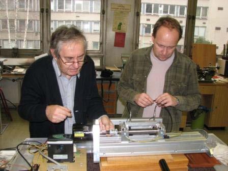
19 Test stand of the TECHLAB design Rigid rotor of the 3 mm diameter Flexible rotor September 5-8, 9
 5 W Rotational speeds up to 3.")
20 The test stand for research of the active vibration control of journal bearings Left bearing Right bearing Motor Bearing span for rigid rotors mm Bearing span for flexible rotors 3 mm Rigid steel shaft diameter 3 mm Flexible shaft reduced between bearings to diameter mm Bronze bushing Flexible membrane coupling Inductive motor (4 Hz) 5 W Rotational speeds up to 3. RPM September 5-8,


21 Movable bushing inserted into the housing Flexible tip Piezoactuator Y Proximity probe Y Bushing Journal Piezoactuator X Proximity probe X September 5-8,
22 Controlable journal bearing O-ring seals Connection rod of the piezoactuator for vertical direction Movable bushing Diameter 3 mm Cylindrical journal bearing Radial clerance of shafts for tests: μm 45 μm 55 μm 8 μm Design TECHLAB (Šimek) September 5-8,


23 Sliding journal bearings with a movable bushing Connecting rod September 5-8, 3


24 Test stand, details Elastic membrane coupling HUCO September 5-8, dspace 4

25 Two-variable control system Stabilization with the use of an electronic feedback The range in which can be maintained vibration at low rotational speed is X: up to 5 μm, Y: up to μm Bushing Piezoelectric actuators Load Journal position + Rotor Proximity system probes + to V to V Amplifier Controller dspace - + Reference September 5-8, 5
26 Troubleshooting -3 X + j * Y -5 X + j * Y micrometer micrometer micrometer micrometer Orbit shapes after putting the test stand into operation (Dec 8) Extending bearing radial clearance from 5 μm to 45 μm (regrinding) Better compensation of the shaft and motor misalignment - no effect Uniformity of motor rotational speed - no or little influence Errors of proximity probes due to the sensor interference influence less than μm Errors of proximity probes probably due to the material inhomogeneity - significant impact, greater than μm September 5-8, 6

27 Main problems which are arising when the test stand was put into operation Choice of lubricating oil determining the journal losses due to the friction Mounting of piezoactuators to avoid torsional loading and enable adjusting position at the accuracy of micrometers Choice of lubricating oil Concerning a lubricant it was initially used the hydraulic oil of the VG 3 class (kinematic viscosity of up to 3 mm /s at 4 C) and then bearing special oil for highspeed grinder spindle bearing of the OL-P3 type (kinematic viscosity.5 to 4 mm /s at 4 C ). September 5-8, 7
![Accuracy of the shaft position measurements Machining-error (non-circularity) is less than μm September 5-8, Disp X [micrometers] -36-38 -4-4 Sensor based on the capacitive principle Micro Epsilon](/docs-images/84/90694754/images/28-0.jpg "Schenck (Brüel & Kjær ) capancdt IN 85CS5 IN-85 capancdt CS5-64 Instability onset -44 Random error -46 3 6 Disp X [micrometer] Sensor based on the eddy current principle -66-68 -7-7 -74 Periodic")
28 Accuracy of the shaft position measurements Machining-error (non-circularity) is less than μm September 5-8, Disp X [micrometers] Sensor based on the capacitive principle Micro Epsilon Schenck (Brüel & Kjær ) capancdt IN 85CS5 IN-85 capancdt CS5-64 Instability onset -44 Random error Disp X [micrometer] Sensor based on the eddy current principle Periodic error Bearing walls 8
29 Multispectra of shaft position displacements λx X capancdt CS5, Micro Epsilon RMS db/ref mm Capacitive sensor to μm to μm to μm Frequency [Hz] RPM 364 db = mm - db =. mm -8 db =. μm λx September 5-8, X IN-85, Schenck (Brüel & Kjær ) Frequency [Hz] X 3X 4X RMS db/ref mm RPM to μm to μm. to μm Eddy current sensor X First harmonic of the rotational frequency X Second harmonic 9


30 Piezoactuator mount Flexible tips Fine adjustment of the piezoactuator position September 5-8, 3
31 Force acting at the bushing vs. bushing displacement in horizontal direction (axis X) Force [N] Displacement [µm] Displacement Force 5.5x 6 N/m September 5-8, 3
32 Arrangement of piezoactuators Piezoactuator Y Connecting rod O-ring seal Force Low voltage piezoactuator PI P Stiffness 4 x 6 N/m Piezoactuator X 3 N Voltage Bushing 5.5x 6 N/m Stiffness of the O-ring seal 77 9 μm Displacement - + Control variable range September 5-8, 3


33 Measurement using PULSE, the BK signal analyzer Active vibration control OFF ON September 5-8, 33
34 Time history of the rotor RPM Active vibration control OFF Active vibration control ON 8 Active Control OFF 8 Active Control ON 6 6 RPM 4 RPM The rate of increase speed is the same September 5-8, 34
35 Effect of the active vibration control on the instability onset Disp Y [micron] Disp X [micron] Actuator Y [V] Actuator X [V] OFF K = P Active Control OFF September 5-8, 8 4 Disp Y [micron] Disp X [micron] Actuator Y [V] Actuator X [V] K P Active Control ON RPM 734 RPM ON Active control ON Active control OFF 35
36 Effect of the controller gain on the instability onset K = =. 5% gain. 9 Full gain Disp X [micron] P Active Control OFF 43 RPM K P Disp X [micron] Active Control ON 6 RPM K P Disp X [micron] Active Control ON 734 RPM Disp Y [micron] Disp Y [micron] Disp Y [micron] Actuator X 5 Actuator X 5 Actuator X Actuator Y 5 Actuator Y 5 Actuator Y September 5-8,
37 Correction of eddy-current sensor errors Averages per a complete revolution Horizontal direction Controlled variable Vertical disp [µm] Vertical direction RPM OFF ON Control variable Horiyontal LVPZT - Voltage [V] Vertical PVZT - Voltage [V] RPM RPM


38 Experiments with active vibration control Active vibration control OFF K = ON K P. 7 P RPM 63 RPM 8 Pos X Pos X Pos Y Pos Y Y 9s controllable bushing coupling motor Actuator X ON OFF X Actuator Y September 5-8, 38

39 Bently Nevada Rotorkit behavior at low rotational speed RPM Tachometer : Pulse positions (Time N) Orbit Plot : X = Náběh : Time X, Y = Náběh : Time Y micron Time History : Náběh : Time X micron micron September 5-8, 39
40 Right bearing (closer to motor) Active vibration control Disp X [micron] OFF Active Control OFF Disp X [micron] ON Active Control ON Horiyontal displ [micrometer] Initial position Journal displacement DispY [micron] Disp Y [micron] Vertival displ [micrometer] September 5-8, 4

41 Other publications on the same topic. The use of piezoactuators C. Carmignani, P. Forte, E. Rustighi, ACTIVE CONTROL OF ROTOR VIBRATIONS BY MEANS OF PIEZOELECTRIC ACTUATORS, Proceedings of DETC, ASME Design Engineering Technical Conference and Computers and Information in Engineering Conference September 5-8, University of Pisa, Italy 4

42 Other publications on the same topic. Active vibration control H. Y. Lau, K. P. Liu, Member, IAENG, W. Wang, and P. L. Wong Feasibility of Using Giant magnetostrictive material (GMM) Based Actuators in Active Control of Journal Bearing System, Proceedings of the World Congress on Engineering 9 Vol II, WCE 9, July - 3, 9, London, U.K. Department of Manufacturing Engineering and Engineering Management, City University of Hong Kong September 5-8, 4


43 Other publications on the same topic. Active vibration control F. Lebo, S. Rinderknecht, Modellbasierte Regelung eines skalierten elastischen Flugtriebwerkrotors mit Piezostapelaktoren, Proceedings of SIRM 9. Internationale Tagung Schwingungen in rotierenden Maschinen, Darmstadt, Deutschland,. 3. Februar Institut für Mechatronische Systeme im Maschinenbau, Technische Universität Darmstadt September 5-8, 43
44 Conclusion Active vibration control (AVC) of the hydrodynamic bearings was put into operation AVC considerably extends the operating speed range of cylindrical bearings The journal can be positioned with precision of micrometers Experiments with active vibration control confirm the validity of the mathematical models which were used for predicting the behavior of the shaft inside the bearing housings The test stand is a suitable tool to study the behavior of hydrodynamic bearings September 5-8, 44


45 Colleagues who contributed to putting the test rig into operation Jan, September 5-8, 45
A SIMULATION STUDY OF THE ROTOR VIBRATION IN A JOURNAL BEARING
 Engineering MECHANICS, Vol. 15, 2008, No. 6, p. 461 470 461 A SIMULATION STUDY OF THE ROTOR VIBRATION IN A JOURNAL BEARING JiříTůma*, Alena Bilošová**, Jiří Šimek***, Rudolf Svoboda*** The paper deals
FULL SPECTRUM ANALYSIS IN JOURNAL BEARING DIAGNOSTICS
 FULL SPECTRUM ANALYSIS IN JOURNAL BEARING DIAGNOSTICS Jiří Tůma and Jan Biloš VŠB-Technical University of Ostrava 17. listopadu 15, 78 33 Ostrava, Czech Republic, jiri.tuma@vsb.cz Abstract: The topic of
Experimental Investigations of Whirl Speeds of a Rotor on Hydrodynamic Spiral Journal Bearings Under Flooded Lubrication
 International Conference on Fluid Dynamics and Thermodynamics Technologies (FDTT ) IPCSIT vol.33() () IACSIT Press, Singapore Experimental Investigations of Whirl Speeds of a Rotor on Hydrodynamic Spiral
SAMCEF For ROTORS. Chapter 1 : Physical Aspects of rotor dynamics. This document is the property of SAMTECH S.A. MEF A, Page 1
 SAMCEF For ROTORS Chapter 1 : Physical Aspects of rotor dynamics This document is the property of SAMTECH S.A. MEF 101-01-A, Page 1 Table of Contents rotor dynamics Introduction Rotating parts Gyroscopic
Robust shaft design to compensate deformation in the hub press fitting and disk clamping process of 2.5 HDDs
 DOI 10.1007/s00542-016-2850-2 TECHNICAL PAPER Robust shaft design to compensate deformation in the hub press fitting and disk clamping process of 2.5 HDDs Bumcho Kim 1,2 Minho Lee 3 Gunhee Jang 3 Received:
USING ROTOR KIT BENTLY NEVADA FOR EXPERIMENTS WITH AEROSTATIC BEARINGS
 USING ROTOR KIT BENTLY NEVADA FOR EXPERIMENTS WITH AEROSTATIC BEARINGS ŠIMEK, J. 1, KOZÁNEK, J., STEINBAUER, P., NEUSSER, Z. 3 1 TECHLAB Ltd., Prague, Institute of Thermomechanics AS CR 3 CTU in Prague,
Foundations of Ultraprecision Mechanism Design
 Foundations of Ultraprecision Mechanism Design S.T. Smith University of North Carolina at Charlotte, USA and D.G. Chetwynd University of Warwick, UK GORDON AND BREACH SCIENCE PUBLISHERS Switzerland Australia
Effect of an hourglass shaped sleeve on the performance of the fluid dynamic bearings of a HDD spindle motor
 DOI 10.1007/s00542-014-2136-5 Technical Paper Effect of an hourglass shaped sleeve on the performance of the fluid dynamic bearings of a HDD spindle motor Jihoon Lee Minho Lee Gunhee Jang Received: 14
PROJECT 2 DYNAMICS OF MACHINES 41514
 PROJECT 2 DYNAMICS OF MACHINES 41514 Dynamics of Rotor-Bearing System Lateral Vibrations and Stability Threshold of Rotors Supported On Hydrodynamic Bearing and Ball Bearing. Ilmar Ferreira Santos, Prof.
Numerical analysis of three-lobe journal bearing with CFD and FSI
 Numerical analysis of three-lobe journal bearing with CFD and FSI Pankaj Khachane 1, Dinesh Dhande 2 1PG Student at Department of Mechanical Engineering, AISSMSCOE Pune, Maharashtra, India 2Assistant Professor
WORK SHEET FOR MEP311
 EXPERIMENT II-1A STUDY OF PRESSURE DISTRIBUTIONS IN LUBRICATING OIL FILMS USING MICHELL TILTING PAD APPARATUS OBJECTIVE To study generation of pressure profile along and across the thick fluid film (converging,
Nonlinear effects on the rotor driven by a motor with limited power
 Applied and Computational Mechanics 1 (007) 603-61 Nonlinear effects on the rotor driven by a motor with limited power L. Pst Institute of Thermomechanics, Academy of Sciences of CR, Dolejškova 5,18 00
The Phenomena of Oil Whirl and Oil Whip
 Ali M. Al-Shurafa, Vibration Engineer Saudi Electricity Company- Ghazlan Power Plant Saudi Arabia ashurafa@hotmail.com The Phenomena of Oil Whirl and Oil Whip 1. Introduction Large machines mounted on
Research Article Response of a Warped Flexible Rotor with a Fluid Bearing
 Hindawi Publishing Corporation International Journal of Rotating Machinery Volume 8, Article ID 753, 9 pages doi:.55/8/753 Research Article Response of a Warped Flexible Rotor with a Fluid Bearing Jim
A novel fluid-structure interaction model for lubricating gaps of piston machines
 Fluid Structure Interaction V 13 A novel fluid-structure interaction model for lubricating gaps of piston machines M. Pelosi & M. Ivantysynova Department of Agricultural and Biological Engineering and
MODELLING AND TESTING OF AN ERF VIBRATION DAMPER FOR LIGHT ROTORS WITH LARGE AMPLITUDES
 MODELLING AND TESTING OF AN ERF VIBRATION DAMPER FOR LIGHT ROTORS WITH LARGE AMPLITUDES Jens Bauer, bauer@sdy.tu-darmstadt.de Institute of Structural Dynamics, Technische Universität Darmstadt, Germany
SCHOOL OF COMPUTING, ENGINEERING AND MATHEMATICS SEMESTER 1 EXAMINATIONS 2012/2013 XE121. ENGINEERING CONCEPTS (Test)
") s SCHOOL OF COMPUTING, ENGINEERING AND MATHEMATICS SEMESTER EXAMINATIONS 202/203 XE2 ENGINEERING CONCEPTS (Test) Time allowed: TWO hours Answer: Attempt FOUR questions only, a maximum of TWO questions
s SCHOOL OF COMPUTING, ENGINEERING AND MATHEMATICS SEMESTER EXAMINATIONS 202/203 XE2 ENGINEERING CONCEPTS (Test) Time allowed: TWO hours Answer: Attempt FOUR questions only, a maximum of TWO questions
FEEDBACK CONTROL SYSTEMS
 FEEDBAC CONTROL SYSTEMS. Control System Design. Open and Closed-Loop Control Systems 3. Why Closed-Loop Control? 4. Case Study --- Speed Control of a DC Motor 5. Steady-State Errors in Unity Feedback Control
Circular Bearing Performance Parameters with Isothermal and Thermo-Hydrodynamic Approach Using Computational Fluid Dynamics
 Circular Bearing Performance Parameters with Isothermal and Thermo-Hydrodynamic Approach Using Computational Fluid Dynamics Amit Chauhan 1 Department of Mechanical Engineering, University Institute of
Operating Conditions of Floating Ring Annular Seals
 Operating Conditions of Floating Ring Annular Seals Mihai ARGHIR Institut PPRIME, UPR CNRS 3346, Université de Poitiers, ISAE ENSMA, France Antoine MARIOT Safran Aircraft Engines, France Authors Bio Mihai
Theory & Practice of Rotor Dynamics Prof. Rajiv Tiwari Department of Mechanical Engineering Indian Institute of Technology Guwahati
 Theory & Practice of Rotor Dynamics Prof. Rajiv Tiwari Department of Mechanical Engineering Indian Institute of Technology Guwahati Module - 8 Balancing Lecture - 1 Introduce To Rigid Rotor Balancing Till
PARAMETER ESTIMATION IN IMBALANCED NON-LINEAR ROTOR-BEARING SYSTEMS FROM RANDOM RESPONSE
 Journal of Sound and Vibration (1997) 208(1), 1 14 PARAMETER ESTIMATION IN IMBALANCED NON-LINEAR ROTOR-BEARING SYSTEMS FROM RANDOM RESPONSE Department of Mechanical Engineering, Indian Institute of Technology,
Identification of SFD force coefficients Large Clearance Open Ends SFD
 32 nd Turbomachinery Research Consortium Meeting Identification of SFD force coefficients Large Clearance Open Ends SFD TRC-SFD-1-212 Luis San Andrés Mast-Childs Professor May 212 TRC Project 32513/1519FB
Abstract: Paper deals with subject of identification of aerostatic journal bearings dynamic properties with use of Rotor Kit Bently Nevada
 IDENTIFICATION OF STIFFNESS AND DAMPING COEFFICIENTS OF AEROSTATIC JOURNAL BEARING Jan Kozánek Jiří Šimek Pavel Steinbauer Aleš Bílkovský Abstract: Paper deals with subject of identification of aerostatic
CHAPTER 1 INTRODUCTION Hydrodynamic journal bearings are considered to be a vital component of all the rotating machinery. These are used to support
 CHAPTER 1 INTRODUCTION Hydrodynamic journal bearings are considered to be a vital component of all the rotating machinery. These are used to support radial loads under high speed operating conditions.
Influence of Eccentricity and Angular Velocity on Force Effects on Rotor of Magnetorheological Damper
 EPJ Web of Conferences 18, 291 (218) EFM 217 https://doi.org/1.151/epjconf/21818291 Influence of Eccentricity and Angular Velocity on Force Effects on Rotor of Magnetorheological Damper Dominik Šedivý
Theory and Practice of Rotor Dynamics Prof. Rajiv Tiwari Department of Mechanical Engineering Indian Institute of Technology Guwahati
 Theory and Practice of Rotor Dynamics Prof. Rajiv Tiwari Department of Mechanical Engineering Indian Institute of Technology Guwahati Module - 7 Instability in rotor systems Lecture - 4 Steam Whirl and
PROPELLER INDUCED STRUCTURAL VIBRATION THROUGH THE THRUST BEARING
 PROPELLER INDUCED TRUCTURAL VIBRATION THROUGH THE THRUT BEARING Jie Pan, Nabil Farag, Terry Lin and Ross Juniper* DEPARTMENT OF MECHANICAL AND MATERIAL ENGINEERING THE UNIVERITY OF WETERN AUTRALIA 35 TIRLING
Orbit Analysis. Jaafar Alsalaet College of Engineering-University of Basrah
 Orbit Analysis Jaafar Alsalaet College of Engineering-University of Basrah 1. Introduction Orbits are Lissajous patterns of time domain signals that are simultaneously plotted in the X Y coordinate plane
Journal-Bearing Databook
 Tsuneo Someya (Editor) Journal-Bearing Databook With Contributions by T. Someya, J. Mitsui, J. Esaki, S. Saito, Y Kanemitsu, T. Iwatsubo, M.Tanaka, S. Hisa, T. Fujikawa, H. Kanki With 60 Figures and 5
Study of coupling between bending and torsional vibration of cracked rotor system supported by radial active magnetic bearings
 Applied and Computational Mechanics 1 (2007) 427-436 Study of coupling between bending and torsional vibration of cracked rotor system supported by radial active magnetic bearings P. Ferfecki a, * a Center
Stability analysis of a whirling disk-spindle system supported by FDBs with rotating grooves
 Microsyst Technol (011) 17:787 797 DOI 10.1007/s0054-010-111-9 TECHNICAL PAPER Stability analysis of a whirling disk-spindle system supported by FDBs with rotating grooves Jihoon Lee Gunhee Jang Kyungmoon
STATIC AND DYNAMIC CHARACTERISTICS OF HYDRODYNAMIC FOUR- LOBE JOURNAL BEARING WITH COUPLE STRESS LUBRICANTS
 STATIC AND DYNAMIC CHARACTERISTICS OF HYDRODYNAMIC FOUR- LOBE JOURNAL BEARING WITH COUPLE STRESS LUBRICANTS B. Chetti, b.chetti@gmail.com, Institute of sciences and Technology, Center University of Khemis
Sliding Bearings. Fig.(1) (a) Full-journal bearing and (b) partial-journal bearing
 (a) Full-journal bearing and (b) partial-journal bearing") Sliding Bearings The goal of a bearing is to provide relative positioning and rotational freedom while transmitting a load between two parts, commonly a shaft and its housing. The object of lubrication
Sliding Bearings The goal of a bearing is to provide relative positioning and rotational freedom while transmitting a load between two parts, commonly a shaft and its housing. The object of lubrication
Paper GT Luis San Andrés. Bonjin Koo. Sung-Hwa Jeung. Supported by Pratt & Whitney Engines and Turbomachinery Research Consortium
 Proceedings of ASME Turbo Expo 2018: Turbine Technical Conference and Exposition, June 11-15, 2018, Oslo, Norway Paper GT2018-76224 EXPERIMENTAL FORCE COEFFICIENTS FOR TWO SEALED ENDS SQUEEZE FILM DAMPERS
DAMPING AND INERTIA COEFFICIENTS FOR TWO END SEALED SUEEZE FILM DAMPERS WITH A CENTRAL GROOVE: MEASUREMENTS AND PREDICTIONS
 2013 ASME Turbo Expo Conference, June 3-7 2013, San Antonio, TX, USA DAMPING AND INERTIA COEFFICIENTS FOR TWO END SEALED SUEEZE FILM DAMPERS WITH A CENTRAL GROOVE: MEASUREMENTS AND PREDICTIONS Luis San
Response of an Open Ends Squeeze Film Damper to Large Amplitude Impact Loads
 2015 STLE Annual Meeting & Exhibition, May 17-21, 2015, Dallas, TX Response of an Open Ends Squeeze Film Damper to Large Amplitude Impact Loads Luis San Andrés Mast-Childs Chair Professor Fellow STLE Sung-Hwa
New Way Porous Gas Bearings as Seals. Bearings Seals
 New Way Porous Gas Bearings as Seals Bearings Seals 1 New Way Overview Founded January 1994. Aston, Pa. 15 miles south of Philadelphia 54 employees 35,000 sq ft facility, Environmentally Controlled Precision
The SKF model for calculating the frictional moment
 The SKF model for calculating the frictional moment The SKF model for calculating the frictional moment Bearing friction is not constant and depends on certain tribological phenomena that occur in the
1 Introduction. Minho Lee 1 Jihoon Lee 1 Gunhee Jang 1
 DOI 10.1007/s005-015-5-5 TECHNICAL PAPER Stability analysis of a whirling rigid rotor supported by stationary grooved FDBs considering the five degrees of freedom of a general rotor bearing system Minho
ANALYSIS AND IDENTIFICATION IN ROTOR-BEARING SYSTEMS
 ANALYSIS AND IDENTIFICATION IN ROTOR-BEARING SYSTEMS A Lecture Notes Developed under the Curriculum Development Scheme of Quality Improvement Programme at IIT Guwahati Sponsored by All India Council of
Stability of Water-Lubricated, Hydrostatic, Conical Bearings With Spiral Grooves for High-Speed Spindles
 S. Yoshimoto Professor Science University of Tokyo, Department of Mechanical Engineering, 1-3 Kagurazaka Shinjuku-ku, Tokyo 16-8601 Japan S. Oshima Graduate Student Science University of Tokyo, Department
Name: Fall 2014 CLOSED BOOK
 Name: Fall 2014 1. Rod AB with weight W = 40 lb is pinned at A to a vertical axle which rotates with constant angular velocity ω =15 rad/s. The rod position is maintained by a horizontal wire BC. Determine
T20WN. Data Sheet. Torque transducers. Special features. Installation example with bellows couplings. B en
 T20WN Torque transducers Data Sheet Special features - Nominal (rated) torques 0.1 N m, 0.2 N m, 0. N m, 1 N m, 2 N m, N m, 10 N m, 20 N m, 0 N m, 100 N m, 200 N m - Accuracy class: 0.2 - Contactless transmission
a) Find the equation of motion of the system and write it in matrix form.
 Find the equation of motion of the system and write it in matrix form.") .003 Engineering Dynamics Problem Set Problem : Torsional Oscillator Two disks of radius r and r and mass m and m are mounted in series with steel shafts. The shaft between the base and m has length L
.003 Engineering Dynamics Problem Set Problem : Torsional Oscillator Two disks of radius r and r and mass m and m are mounted in series with steel shafts. The shaft between the base and m has length L
Lateral Dynamics of Flexible Rotors Supported by Controllable Gas Bearings Theory & Experiment
 Downloaded from orbit.dtu.dk on: Apr, 19 Lateral Dynamics of Flexible Rotors Supported by Controllable Gas Bearings Theory & Experiment Pierart Vásquez, Fabián Gonzalo; Santos, Ilmar Published in: Proceedings
Contents. Dynamics and control of mechanical systems. Focus on
 Dynamics and control of mechanical systems Date Day 1 (01/08) Day 2 (03/08) Day 3 (05/08) Day 4 (07/08) Day 5 (09/08) Day 6 (11/08) Content Review of the basics of mechanics. Kinematics of rigid bodies
Experimental test of static and dynamic characteristics of tilting-pad thrust bearings
 Special Issue Article Experimental test of static and dynamic characteristics of tilting-pad thrust bearings Advances in Mechanical Engineering 2015, Vol. 7(7) 1 8 Ó The Author(s) 2015 DOI: 10.1177/1687814015593878
Piezoactuators. Jiří Tůma
 Piezoactuators Jiří Tůma 1 Domain Piezoelectric effect Direct piezoelectric effect discovered the brothers Pierre and Jacques Curie. They found that certain crystalline materials (ceramics) having the
Measurement Techniques for Engineers. Motion and Vibration Measurement
 Measurement Techniques for Engineers Motion and Vibration Measurement Introduction Quantities that may need to be measured are velocity, acceleration and vibration amplitude Quantities useful in predicting
Nonlinear Rolling Element Bearings in MADYN 2000 Version 4.3
 - 1 - Nonlinear Rolling Element Bearings in MADYN 2000 Version 4.3 In version 4.3 nonlinear rolling element bearings can be considered for transient analyses. The nonlinear forces are calculated with a
Index. Index. More information. in this web service Cambridge University Press
 A-type elements, 4 7, 18, 31, 168, 198, 202, 219, 220, 222, 225 A-type variables. See Across variable ac current, 172, 251 ac induction motor, 251 Acceleration rotational, 30 translational, 16 Accumulator,
SIMULATION FOR INSTABLE FLOATING OF HYDRODYNAMIC GUIDES DURING ACCELERATION AND AT CONSTANT VELOCITY 1. INTRODUCTION
 Journal of Machine Engineering, 08, Vol. 8, No., 5 5 ISSN 895-7595 (Print) ISSN 9-807 (Online) Received: December 07 / Accepted: 0 August 08 / Published online: 8 September 08 Yingying ZHANG * Volker WITTSTOCK
Manufacturing Equipment Control
 QUESTION 1 An electric drive spindle has the following parameters: J m = 2 1 3 kg m 2, R a = 8 Ω, K t =.5 N m/a, K v =.5 V/(rad/s), K a = 2, J s = 4 1 2 kg m 2, and K s =.3. Ignore electrical dynamics
Chapter 14 Periodic Motion
 Chapter 14 Periodic Motion 1 Describing Oscillation First, we want to describe the kinematical and dynamical quantities associated with Simple Harmonic Motion (SHM), for example, x, v x, a x, and F x.
UNIVERSITY OF BOLTON SCHOOL OF ENGINEERING BENG (HONS) IN MECHANICAL ENGINEERING SEMESTER 1EXAMINATION 2017/2018
 IN MECHANICAL ENGINEERING SEMESTER 1EXAMINATION 2017/2018") ENG00 UNIVERSITY OF BOLTON SCHOOL OF ENGINEERING BENG (HONS) IN MECHANICAL ENGINEERING SEMESTER EXAMINATION 07/08 ADVANCED THERMOFLUIDS & CONTROL SYSTEMS MODULE NO: AME6005 Date: 8 January 08 Time: 0.00.00
ENG00 UNIVERSITY OF BOLTON SCHOOL OF ENGINEERING BENG (HONS) IN MECHANICAL ENGINEERING SEMESTER EXAMINATION 07/08 ADVANCED THERMOFLUIDS & CONTROL SYSTEMS MODULE NO: AME6005 Date: 8 January 08 Time: 0.00.00
Dynamic Tests on Ring Shear Apparatus
 , July 1-3, 2015, London, U.K. Dynamic Tests on Ring Shear Apparatus G. Di Massa Member IAENG, S. Pagano, M. Ramondini Abstract Ring shear apparatus are used to determine the ultimate shear strength of
ROTATING MACHINERY VIBRATION
 SECOND EDITION ROTATING MACHINERY VIBRATION From Analysis to Troubleshooting MAURICE L. ADAMS, JR Case Western Reserve University Cleveland, Ohio W^ C\ CRC Press У Taylor &. Francis Group Boca Raton London
Control for. Maarten Steinbuch Dept. Mechanical Engineering Control Systems Technology Group TU/e
 Control for Maarten Steinbuch Dept. Mechanical Engineering Control Systems Technology Group TU/e Motion Systems m F Introduction Timedomain tuning Frequency domain & stability Filters Feedforward Servo-oriented
Dr Ian R. Manchester Dr Ian R. Manchester AMME 3500 : Review
 Week Date Content Notes 1 6 Mar Introduction 2 13 Mar Frequency Domain Modelling 3 20 Mar Transient Performance and the s-plane 4 27 Mar Block Diagrams Assign 1 Due 5 3 Apr Feedback System Characteristics
FEDSM99 S-291 AXIAL ROTOR OSCILLATIONS IN CRYOGENIC FLUID MACHINERY
 Proceedings of the 3 rd ASME/JSME Joint Fluids Engineering Conference 1999 ASME Fluids Engineering Division Summer Meeting July 18-23 1999, San Francisco, California FEDSM99 S-291 AXIAL ROTOR OSCILLATIONS
Introduction to Control (034040) lecture no. 2
 lecture no. 2") Introduction to Control (034040) lecture no. 2 Leonid Mirkin Faculty of Mechanical Engineering Technion IIT Setup: Abstract control problem to begin with y P(s) u where P is a plant u is a control signal
Introduction to Control (034040) lecture no. 2 Leonid Mirkin Faculty of Mechanical Engineering Technion IIT Setup: Abstract control problem to begin with y P(s) u where P is a plant u is a control signal
VIBRATION ANALYSIS AND REPAIR PROCESS FOR THE VENTILATION SYSTEM FOR SMOKE DRAIN IN THE THERMAL POWER PLANT
 Applied Engineering Letters Vol.3, No.1, 40-45 (2018) e-issn: 2466-4847 VIBRATION ANALYSIS AND REPAIR PROCESS FOR THE VENTILATION SYSTEM FOR SMOKE DRAIN IN THE THERMAL POWER PLANT Original scientific paper
Analysis of Fluid Film Stiffness and Damping coefficient for A Circular Journal Bearing with Micropolar Fluid
 et International Journal on Emerging Technologies 5(1): 206-211(2014) ISSN No. (Print) : 0975-8364 ISSN No. (Online) : 2249-3255 Analysis of Fluid Film Stiffness Damping coefficient for A Circular Journal
Nonlinear Dynamic Analysis of a Hydrodynamic Journal Bearing Considering the Effect of a Rotating or Stationary Herringbone Groove
 G. H. Jang e-mail: ghjang@hanyang.ac.kr J. W. Yoon PREM, Department of Mechanical Engineering, Hanyang University, Seoul, 133-791, Korea Nonlinear Dynamic Analysis of a Hydrodynamic Journal Bearing Considering
DEVELOPMENT OF TOOL FOR THE IDENTIFICATION OF STIFFNESS AND DAMPING COEFFICIENTS OF JOURNAL BEARING
 DEVELOPMENT OF TOOL FOR THE IDENTIFICATION OF STIFFNESS AND DAMPING COEFFICIENTS OF JOURNAL BEARING Sampath Kumar B 1 and G.Satish Babu 2 1 P.G student, Department of mechanical engineering, JNTUH College
Stability Analysis of a Hydrodynamic Journal Bearing With Rotating Herringbone Grooves
 G. H. Jang e-mail: ghjang@hanyang.ac.kr J. W. Yoon PREM, Department of Mechanical Engineering, Hanyang University, Seoul, 33-79, Korea Stability Analysis of a Hydrodynamic Journal Bearing With Rotating
NOISE REDUCTION OF THE DIFFERENTIAL SLEEVE BEARING
 Engineering MECHANICS, Vol. 16, 29, No. 2, p. 93 12 93 NOISE REDUCTION OF THE DIFFERENTIAL SLEEVE BEARING Ivan Mazůrek, Milan Klapka, Jakub Roupec* This article describes a technique for noise reduction
Basics of rotordynamics 2
 Basics of rotordynamics Jeffcott rotor 3 M A O a rigid rotor disk rotates at angular frequency W massless shaft acts as a spring restoring displacements disk can move only in the plane defined by axes
AP Physics C Mechanics Objectives
 AP Physics C Mechanics Objectives I. KINEMATICS A. Motion in One Dimension 1. The relationships among position, velocity and acceleration a. Given a graph of position vs. time, identify or sketch a graph
Dynamic analysis of a HDD spindle system with FDBs due to the bearing width and asymmetric grooves of journal bearing
 Microsystem Technologies Micro- and Nanosystems Information Storage and Pro Springer-Verlag 2005 10.1007/s00542-005-0606-5 Technical paper Dynamic analysis of a HDD spindle system with FDBs due to the
Active control of multi-input hydraulic journal bearing system
 Journal of Physics: Conference Series PAPER OPEN ACCESS Active control of multi-input hydraulic journal bearing system To cite this article: Jen-Chen Chuang et al 2016 J. Phys.: Conf. Ser. 744 012062 View
KNIFE EDGE FLAT ROLLER
 EXPERIMENT N0. 1 To Determine jumping speed of cam Equipment: Cam Analysis Machine Aim: To determine jumping speed of Cam Formulae used: Upward inertial force = Wvω 2 /g Downward force = W + Ks For good
Kinematics, Dynamics, and Vibrations FE Review Session. Dr. David Herrin March 27, 2012
 Kinematics, Dynamics, and Vibrations FE Review Session Dr. David Herrin March 7, 0 Example A 0 g ball is released vertically from a height of 0 m. The ball strikes a horizontal surface and bounces back.
State Space Representation
 ME Homework #6 State Space Representation Last Updated September 6 6. From the homework problems on the following pages 5. 5. 5.6 5.7. 5.6 Chapter 5 Homework Problems 5.6. Simulation of Linear and Nonlinear
Open Research Online The Open University s repository of research publications and other research outputs
 Open Research Online The Open University s repository of research publications and other research outputs Developments in efficiency and stability of fluid film bearings using new designs and test techniques
Contact problems in rotor systems
 Contact problems in rotor systems Liudmila Banakh Mechanical Engineering Research Institute of RAS, Moscow, Russia E-mail: banl@inbox.ru (Received 18 July 2016; accepted 24 August 2016) Abstract. We consider
LEAKAGE AND ROTORDYNAMIC FORCE COEFFICIENTS OF A THREE-WAVE (AIR IN OIL) WET ANNULAR SEAL: MEASUREMENTS AND PREDICTIONS
 WET ANNULAR SEAL: MEASUREMENTS AND PREDICTIONS") Proceedings of ASME Turbo Expo 2018: Turbomachinery Technical Conference and Exposition, June 11-15, 2018, Oslo, Norway Paper GT2018-75200 LEAKAGE AND ROTORDYNAMIC FORCE COEFFICIENTS OF A THREE-WAVE (AIR
Proceedings of ASME Turbo Expo 2018: Turbomachinery Technical Conference and Exposition, June 11-15, 2018, Oslo, Norway Paper GT2018-75200 LEAKAGE AND ROTORDYNAMIC FORCE COEFFICIENTS OF A THREE-WAVE (AIR
Linear and Nonlinear Analysis of Plain Journal Bearings Lubricated With Couple Stress Fluid
 ISSN 2395-1621 Linear and Nonlinear Analysis of Plain Journal Bearings Lubricated With Couple Stress Fluid #1 Deepali Kangude 1 deepalikangude94@gmail.com 1 P.G. student Mechanical Department, DYPIET Pimpri,
This equation of motion may be solved either by differential equation method or by graphical method as discussed below:
 2.15. Frequency of Under Damped Forced Vibrations Consider a system consisting of spring, mass and damper as shown in Fig. 22. Let the system is acted upon by an external periodic (i.e. simple harmonic)
An experimental and numerical analysis of the performances of a Wankel steam expander
 IV International Seminar on ORC Power Systems, ORC 2017 13-15 September 2017, Milano, Italy An experimental and numerical analysis of the performances of a Wankel steam expander M. Francesconi, G. Caposciutti,
A nonlinear dynamic vibration model of defective bearings: The importance of modelling the finite size of rolling elements
 A nonlinear dynamic vibration model of defective bearings: The importance of modelling the finite size of rolling elements Alireza Moazenahmadi, Dick Petersen and Carl Howard School of Mechanical Engineering,
Experimental Study on the Velocity Dependent Drag Coefficient and Friction in an Automatic Ball Balancer
 TCHNISCH MCHANIK, 7, 1, (2017), 62 68 submitted: May 19, 2017 xperimental Study on the Velocity Dependent Drag Coefficient and Friction in an Automatic Ball Balancer L. Spannan, C. Daniel,. Woschke The
41514 Dynamics of Machinery
 41514 Dynamics of Machinery Theory, Experiment, Phenomenology and Industrial Applications Ilmar (Iumár) Ferreira Santos 1. Course Structure 2. Objectives 3. Theoretical and Experimental Example 4. Industrial
1820. Selection of torsional vibration damper based on the results of simulation
 8. Selection of torsional vibration damper based on the results of simulation Tomasz Matyja, Bogusław Łazarz Silesian University of Technology, Faculty of Transport, Gliwice, Poland Corresponding author
Influence of friction coefficient on rubbing behavior of oil bearing rotor system
 Influence of friction coefficient on rubbing behavior of oil bearing rotor system Changliang Tang 1, Jinfu ang 2, Dongjiang Han 3, Huan Lei 4, Long Hao 5, Tianyu Zhang 6 1, 2, 3, 4, 5 Institute of Engineering
Research Article Stability Analysis of Journal Bearing: Dynamic Characteristics
 Research Journal of Applied Sciences, Engineering and Technology 9(1): 47-52, 2015 DOI:10.19026/rjaset.9.1375 ISSN: 2040-7459; e-issn: 2040-7467 2015 Maxwell Scientific Publication Corp. Submitted: July
Nonlinear effects on the rotor driven by a motor with limited power
 Applied and Computational Mechanics 1 (007) 603-61 Nonlinear effects on the rotor driven by a motor with limited power L. Půst Institute of Thermomechanics, Academy of Sciences of CR, Dolejkova 5,18 00
Dynamics of Machinery
 Dynamics of Machinery Two Mark Questions & Answers Varun B Page 1 Force Analysis 1. Define inertia force. Inertia force is an imaginary force, which when acts upon a rigid body, brings it to an equilibrium
Analysis of Hydrodynamic Journal Bearing Using CFD and FSI Technique
 Analysis of Hydrodynamic Journal Bearing Using CFD and FSI Technique Priyanka Tiwari M.E. Student of Government Engineering College Jabalpur, M.P.-India Veerendra Kumar Principal of Government Engineering
1415. Effects of different disc locations on oil-film instability in a rotor system
 1415. Effects of different disc locations on oil-film instability in a rotor system Hui Ma 1, Xueling Wang 2, Heqiang Niu 3, Hui Li 4 School of Mechanical Engineering and Automation, Northeastern University,
Evaluation of active structural vibration control strategies in milling process
 Evaluation of active structural vibration control strategies in milling process Monnin, J. (a); Wegener, K. (a) a) Institute of Machine Tools and Manufacturing, Zurich, Switzerland Keywords: Mechatronics,
Theory and Practice of Rotor Dynamics Prof. Dr. Rajiv Tiwari Department of Mechanical Engineering Indian Institute of Technology Guwahati
 Theory and Practice of Rotor Dynamics Prof. Dr. Rajiv Tiwari Department of Mechanical Engineering Indian Institute of Technology Guwahati Module - 2 Simpul Rotors Lecture - 2 Jeffcott Rotor Model In the
Influence of electromagnetic stiffness on coupled micro vibrations generated by solar array drive assembly
 Influence of electromagnetic stiffness on coupled micro vibrations generated by solar array drive assembly Mariyam Sattar 1, Cheng Wei 2, Awais Jalali 3 1, 2 Beihang University of Aeronautics and Astronautics,
Step 1: Mathematical Modeling
 083 Mechanical Vibrations Lesson Vibration Analysis Procedure The analysis of a vibrating system usually involves four steps: mathematical modeling derivation of the governing uations solution of the uations
Dynamics and control of mechanical systems
 Dynamics and control of mechanical systems Date Day 1 (03/05) - 05/05 Day 2 (07/05) Day 3 (09/05) Day 4 (11/05) Day 5 (14/05) Day 6 (16/05) Content Review of the basics of mechanics. Kinematics of rigid
TOPIC E: OSCILLATIONS SPRING 2019
 TOPIC E: OSCILLATIONS SPRING 2019 1. Introduction 1.1 Overview 1.2 Degrees of freedom 1.3 Simple harmonic motion 2. Undamped free oscillation 2.1 Generalised mass-spring system: simple harmonic motion
EQUIVALENT SINGLE-DEGREE-OF-FREEDOM SYSTEM AND FREE VIBRATION
 1 EQUIVALENT SINGLE-DEGREE-OF-FREEDOM SYSTEM AND FREE VIBRATION The course on Mechanical Vibration is an important part of the Mechanical Engineering undergraduate curriculum. It is necessary for the development
Towards Rotordynamic Analysis with COMSOL Multiphysics
 Towards Rotordynamic Analysis with COMSOL Multiphysics Martin Karlsson *1, and Jean-Claude Luneno 1 1 ÅF Sound & Vibration *Corresponding author: SE-169 99 Stockholm, martin.r.karlsson@afconsult.com Abstract: