Hybrid RANS/LES of plane jets impinging on a flat plate at small nozzle-plate distances
|
|
|
- Beatrix Lawrence
- 5 years ago
- Views:
Transcription
1 Arch. Mech., 65, 2, pp , Warszawa 213 Hybrid RANS/LES of plane jets impinging on a flat plate at small nozzle-plate distances S. KUBACKI 1), J. ROKICKI 1), E. DICK 2), J. DEGROOTE 2), J. VIERENDEELS 2) 1) Institute of Aeronautics and Applied Mechanics Warsaw University of Technology Nowowiejska , Warsaw, Poland slawomir.kubacki@meil.pw.edu.pl 2) Department of Flow, Heat and Combustion Mechanics Ghent University St. Pietersnieuwstraat 41, B-9, Ghent, Belgium A k-ω based hybrid RANS/LES (Reynolds-averaged Navier Stokes/large eddy simulation) model is tested for simulation of plane impinging jets at various nozzle-plate distances (H/B), where H is the distance and B is the slot s width) and various Reynolds numbers (based on the slot s width and the velocity in the symmetry plane). The studied combinations are H/B = 2 for Re = 1, H/B = 4 for Re = 18 and H/B = 9.2 for Re = 2. The focus is on small distance of the nozzle exit to the plate. In LES mode, the hybrid RANS/LES model uses two definitions of the local grid size, one based on the maximum distance between the cell faces in the destruction term of the turbulent kinetic energy equation and one based on the cube root of the cell volume in the eddy-viscosity formula. This allows accounting for flow inhomogeneity on anisotropic grids. In RANS mode, the hybrid model turns into the newest version of the k-ω model by Wilcox. Key words: plane impinging jet, turbulence modelling, hybrid RANS/LES model, large eddy simulation. Copyright c 213 by IPPT PAN 1. Introduction Plane impinging jets were studied experimentally [1 8] and numerically using LES [9 11] in order to provide a database for assessment of the qualities of turbulence models, to study the influence of the inlet conditions on the impingement plate shear stress and heat transfer distributions and to understand the relationship between heat transfer and shear stress along the plate. Direct numerical simulations (DNS) were performed [11, 12] to clarify the effect of the inlet disturbances on the flow and heat transfer characteristics along the impingement plate or to study the effect of nozzle-plate distance on the location of the secondary peak in the shear stress and the heat transfer profiles. The predic-
2 144 S. Kubacki et al. tive qualities of various RANS models were verified by Fernandez et al. [13] and Jaramillo et al. [14], among others, for plane impinging jets at various nozzle-plate distances and Reynolds numbers. For large nozzle-plate distance, RANS models suffer from difficulties in reproducing the turbulence mixing in the developing shear layers of the jet as well as in capturing the correct level of shear stress and heat transfer in the impact zone. This poses a difficulty in application of the RANS-based techniques in analysis of complex flow systems in which free jet development and its subsequent impingement largely determine the level of the wall shear stress and local heat transfer rate along the impingement wall. For small nozzle-plate distance, where the flow in the impact zone is physically laminar, the prediction of the shear stress and heat transfer levels in the stagnation flow region basically agree with RANS models due to use of stress limiters which damp most of the turbulence in the impact zone. The transition from laminar to turbulent state in the developing boundary layer on the plate is completely ignored by RANS models. In the present work, a k-ω based hybrid RANS/LES model and the k-ω RANS model of Wilcox [15] are employed to study their applicability in reproducing the plane impinging jet flow characteristics at low nozzle-plate distances (H/B = 2 and 4) and at various Reynolds numbers (1 and 18 ). This means for impact of the jet onto the plate before complete mixing of the shear layers. The centre of the impact zone is then in laminar state and the developing boundary layer on the plate undergoes transition to turbulent state. The transitional flow cannot be correctly simulated with the RANS turbulence model, but we will demonstrate that the hybrid model is basically correct. The test case with the large nozzle-to-plate distance (H/B = 9.2, Re = 2) is only meant to demonstrate the correct setting of the inflow conditions. The reliability of the hybrid model will be demonstrated by comparing results of mean velocity profiles, profiles of fluctuating velocity components and skin friction on the plate with results from LES using a dynamic Smagorinsky model and experiments. The hybrid RANS/LES model analysed here belongs to the class of unified DES-type approaches, as first proposed by Strelets [16]. For a classification of hybrid approaches, we refer to Fröhlich and von Terzi [17]. The local grid size, replacing the turbulent length scale in the LES mode of the hybrid model, is introduced in both the destruction term of the turbulent kinetic energy equation and in the eddy-viscosity formula, according to methods first proposed by Davidson and Peng [18], Kok et al. [19] and Yan et al. [2]. In RANS mode, the newest version of the k-ω model of Wilcox [15] is recovered. Two definitions of the local grid size are used to better account for flow inhomogeneity on anisotropic grids. The model was already tested on round impinging jets [21]. A simpler version was tested on plane impinging jets at large nozzle-plate distances by Kubacki and Dick [22] and Kubacki et al. [23].
3 2. The hybrid RANS/LES model Hybrid RANS/LES of plane jets The transport equations for the turbulent kinetic energy k and the inverse of the turbulent time scale (frequency) ω read: ( k t + (U jk) U i = τ ij max β k 3/2 ) kω, + [( ν+σ k ) ] k (2.1), x j x j C DES x j ω x j ω t + (U jω) = α ω x j k τ U i ij βω 2 + σ d k ω + [( ν+σ k ) ] ω (2.2). x j ω x j x j x j ω x j In these equations, ν is the kinematic molecular viscosity, and the modelled stress tensor and the shear rate tensor are and τ ij = 2ν t S ij 2/3kδ ij S ij = 1/2( U i / x j + U j / x i ) 1/3( U k / x k )δ ij, respectively. The local grid size is defined by = max( x, y, z ) where x, y, z denote the distances between the cell faces in x, y and z directions. The grid size is multiplied with a tuning constant C DES, which we derive later. The basic model is the k-ω RANS of Wilcox [15]. The motivation for the modification of the destruction term in (2.1) is that the dissipation in the k-ω RANS model is ε = β kω = k 3/2 /L t, where the turbulent length scale is L t = k 1/2 /(β ω). This means that in the dissipation term, the turbulent length scale is replaced by the grid size when the model transfers to LES mode. The choice of the grid size measure is crucial in any LES-like formulation [17, 24, 25]. The literature shows that there is a preference for the maximum size in a DES (detached eddy simulation) formulation [2, 25], while there is a preference for the cube root measure in an LES formulation [17, 24]. For the length scale in the k-equation (2.1), we take the maximum size, as by the substitution of the length scale, a detached eddy simulation (DES) model is obtained, in the manner as first proposed by Strelets [16]. The closure coefficients are [15] β =.9, α =.52, β = β f β, β =.78, f β = χ ω 1 + 1χ ω, χ ω = σ =.5, σ =.6, σ do =.125, Ω ij Ω jk S ki (β ω) 3, σ d = for k x j ω x j, σ do where Ω ij =1/2( U i / x j U j / x i ) is the vorticity tensor. for k x j ω x j >,
4 146 S. Kubacki et al. The eddy-viscosity is defined according to Davidson and Peng [18] and Kok et al. [19] by ( ) k (2.3) ν t = min ω,β C DES k LES, where LES =( x y z ) 1/3. The motivation for this modification is that the RANS eddy viscosity is ν t = β L t k 1/2. This means that also in the eddy-viscosity expression, the turbulent length scale is replaced by the grid size. The chosen grid size is here the cube root measure- the typical LES grid size. The grid size is multiplied with the tuning constant C DES. The justification for using different grid scales in Eq. (2.3) and in the k-equation (Eq. (2.1)) is that, under local equilibrium (production of k equal to dissipation of k), the eddy viscosity reduces in LES mode to a Smagorinsky subgrid viscosity (2.4) ν t = ( ( ) 1/4 ) 2 C s LES S, LES with C s = (β ) 3/4 C DES set to the usual value.1, which gives C DES =.686 and with the magnitude of the shear rate S = (2S ij S ij ) 1/2. The role of the term ( / LES ) 1/4 is to increase the eddy viscosity on high aspect ratio cells, with respect to the value obtained by the cube root grid size in all turbulence length scale substitutions. We follow here the approach by Scotti et al. [24], who proved much better predictive qualities of LES on anisotropic grids by an increased eddy viscosity. For the RANS simulations [15], a stress limiter is applied. This means that the turbulent viscosity ν t is defined by (2.5) ν t = k ω ( ), ω = max 2S ij S ij ω,c lim β with C lim = 7/8. The RANS stress limiter [15] is omitted in Eq. (2.3) in the hybrid RANS/LES model. Tests show that the stress limiter has only negligible effect on the results of impinging jet flows with the hybrid RANS/LES model. The limiter is only significant for the RANS model. As boundary conditions, k = at walls and ω = u 2 τs R /ν in the centre of a cell at a wall, with u τ = (τ w /ρ) 1/2, τ w = µ S, S R = min[(2/k s + ) 2,6/(β ( y + ) 2 )], where y + = y u τ /ν, k s + is a dimensionless roughness height, y is the distance to the wall of the centre of the cell, ρ is the fluid density and µ is the dynamic molecular viscosity. Since the wall is assumed to be hydraulically smooth, the dimensionless roughness height was set to k s + = 4, according to Wilcox [15].
5 Hybrid RANS/LES of plane jets One has to note that the main difference between the newest version of the k-ω model by Wilcox [15] (employed here) and the previous model version [26] is the addition of the cross-diffusion term in the ω-equation (third term on r.h.s. of Eq. (2.2), which limits a spurious sensitivity of the k-ω model to the turbulence quantities specified in the free stream. The other difference is the addition of the stress-limiter in the eddy-viscosity formula (Eq. (2.5)) which limits overprediction of the turbulent shear stress in the stagnation flow regions. 3. Computational framework The computational domain consists of a rectangular box as shown in Fig 1. Details related to the size of the computational domain, coordinate system, boundary conditions and the number of grid points are given in Table 1. The velocity vector is defined by U = Ui + V j + Wk where the unit vectors i, j and k are aligned with the x, y, and z vectors shown in Fig. 1. Fig. 1. Sketch of computational domain, coordinate system and boundary conditions for plane impinging jet simulation at H/B = 4. Periodic conditions are imposed in the z-direction. At the inlet to the computational domain (jet exit) an almost flat mean velocity profile was specified by (3.1) V (x,,z) = V (1 (2x/B) 14 ),
6 148 S. Kubacki et al. Table 1. Length L, height H and width W of the computational domains for simulations performed with the hybrid RANS/LES and LES models and the number of cells N x, N y, N z in x, y and z directions. Case L/B H/B W/B N x N y N z N tot (M) H/B = 9.2, Re = π H/B = 4, Re = π H/B = 2, Re = 1 (basic) 8 2 π H/B = 2, Re = 1 (fine) 8 2 π where V denotes the mean velocity in the symmetry plane. We show later that the mean velocity profile given by Eq. (3.1) corresponds well with experimental data immediately at the downstream of the slot. For all cases in Table 1, the turbulence intensity at the jet exit was set to Tu =.9% in accordance with the experiments of Zhe and Modi [4]. A similar value of the inlet turbulence intensity, 1%, was used by Ashforth-Frost et al. [3]. We use also the measurements as in [3], for comparison with our numerical results (the experimental set-up in [3], is very similar to the experimental set-up in [4]). The integral length scale was not measured in the inlet plane by Zhe and Modi [4] and Ashforth-Frost et al. [3]. In the present RANS computations, constant values of k and ω were specified at the inlet of the computational domain with Tu =.9%, while the turbulent (integral) length scale L t was specified according to Jaramillo et al. [14], namely L t =.1667B. Uniform inlet profiles of the turbulent quantities are specified by k = 1.5(Tu V ) 2 and ω = k 1/2 /(β L t ). For the hybrid simulations, the vortex method of Fluent was used to generate the resolved fluctuations in the inlet plane [27]. For the LES, random fluctuations were generated in the inlet plane. The full RANS profiles of k and ω were imposed at the jet exit to reproduce the resolved perturbations. With the vortex method, structures smaller than the grid size are not generated. So, the modelled part of the total fluctuating velocity is automatically not taken into account. The modelled k SGS and ω SGS are prescribed by k SGS = (C DES ) 2/3 ε 2/3 = (β kωc DES ) 2/3, ω SGS = ε/(β k SGS ) = ωk/k SGS [21]. This means that the length C DES is used as representative length scale for the subgrid turbulence. The top boundary, at the height of the jet exit, was split into two parts. A confinement wall was specified for a part of the boundary extending from the slot edges up to the streamwise distance x/b = ±13 [4]. A pressure outlet boundary condition was applied for the remaining part of the top boundary as well as in the outflow planes located at x/b = ±4. This means that relative static pressure was prescribed (here, set to zero), as well as the direction of the backflow (which is determined based on the flow direction in the cells adjacent to the boundary) and the values of the transported scalars.
7 Hybrid RANS/LES of plane jets In the RANS model simulations the direction of the backflow was simply set to be normal to the pressure outlet boundary. With the pressure outlet condition imposed, a very low value of the turbulent/subgrid to molecular viscosity ratio was prescribed in the computations using the hybrid and LES models in the flow regions re-entering the computational domain (set here to.1) while the backflow turbulent length scale was set to L t =.1667B. In RANS computations the ratio of the turbulent to molecular viscosity was set to 5 and the turbulent length scale was set to L t =.1667B. No fluctuations were generated with the vortex method at the pressure outlet boundaries with the LES and hybrid RANS/LES models. Periodic boundary conditions have been applied in the spanwise z-direction. The computations using the RANS and the hybrid RANS/LES models have been performed with the Fluent code ver. 12, while the LES simulations have been performed with OpenFOAM. In Fluent, the transport equations (Eqs. (2.1) (2.2)) were implemented with the user-defined scalar functionality. For the hybrid RANS/LES, a TVD-bounded central scheme was applied to the convective terms in the momentum equations, while for LES it was the central differencing scheme with filtering of high-frequency ripples. The second order upwind scheme was used to the convective terms in the k- and ω-equations (hybrid RANS/LES). For RANS, the second order upwind scheme was used for discretisation of the convective terms in all equations. For temporal discretisation (hybrid RANS/LES and LES), a second-order implicit scheme was applied. An implicit time stepping technique was chosen to guarantee stability for large CFL number. The time step was, however, chosen small enough so that the CFLnumber in LES zones was at maximum 2, so that the dissipation due to the time stepping remained small. At each time step, inner iteration steps were applied to lower the residuals for the momentum and the transport equations below 1 4. Similar convergence level was obtained in the steady RANS simulations. For the hybrid RANS/LES and LES model simulations the computational grids have been refined in the shear layer of the jet and in the near-wall regions as shown in Fig. 2. For the hybrid RANS/LES and RANS model computations the maximum value of y + was less than 1 at the impingement plate, and less than 3 at the confinement plate, in LES, y + < 3 at all walls. The numbers of grid points are summarized in Table 1. The hybrid model simulations have been performed on the grids denoted by H/B = 9.2, Re = 2, H/B = 4, Re = 18 and H/B = 2, Re = 1 (basic) in Table 1. The LES model simulation has been performed on the finest grid, consisting of 15.1 million (M) grid points. The RANS simulations have been performed on 2D grids which are cuts in the x-y plane of the 3D grids used for the hybrid RANS/LES model simulations. We refer to our previous work [28] for a discussion of the grid independence in the simulations with the 2D RANS model.
8 15 S. Kubacki et al. a) -1 y/b 1 2 b) x/b 2 1 z/b x/b Fig. 2. View of the computational mesh: a) in the x-y plane and b) in the x-z plane (impingement plate) for simulation with the hybrid RANS/LES model (H/B = 2). 4. Results 4.1. Inlet conditions This section provides a verification of the two types of inlet conditions for simulation of the plane impinging jet with the hybrid RANS/LES model. The first way is using constant values of the turbulent kinetic energy, k, and the turbulent length scale L t at the nozzle exit. The second way is using the exact shape of the inlet k-profile (as measured by Ashforth-Frost et al. [3]), together with a constant value of the turbulent (integral) length scale. The numerical results obtained with the hybrid RANS/LES model (impinging jet with the flat plate) are compared with the free jet flow measurements [4], so in absence of the impingement plate. Note the similar turbulent intensity level at the jet exit in the measurements by Zhe and Modi [4] and Ashforth-Frost et al. [3]. Panels a) and b) of Fig. 3 show the mean and fluctuating y-velocity components at distance y/h =.3 from the nozzle exit for uniform profiles of the turbulent kinetic energy and the turbulent length scale over the inlet plane. The profiles have been averaged in time, in the spanwise z direction, and for positive and negative values of the x-coordinate with respect to the symmetry plane.
9 Hybrid RANS/LES of plane jets It means that the numerical profiles have symmetry in Fig. 3 (also in Fig. 4). The computed mean velocity profile agrees well with the measured mean velocity (Fig. 3a). This justifies the selection of the exponent in Eq. (3.1). The predicted fluctuating velocity profile (Fig. 3b) is in good agreement with measured fluctuating velocity over 6% of the jet width, but some underprediction of the peak values is observed. The peak values of v /V are better captured with the hybrid model further downstream at y/h = 1 as shown in Fig. 3d, but the width of the turbulent shear layer is underestimated. The magnitude of the resolved fluctuating velocity at x/b = ±.5 is significantly higher at distance y/h = 1 (Fig. 3d) than immediately following the jet exit, y/h =.3 (Fig. 3b). This demonstrates that the hybrid model functions properly as the magnitude of the resolved scales gets higher with increasing distance from the jet exit, so when the width of the shear layer grows as a result of the Kelvin Helmholtz instability. Further downstream (y/h = 5.4), the jet spreads strongly (Figs. 3e and 3f). In the simulations, the decay of the mean velocity is much stronger than in experiment. This is accompanied by an abrupt increase of the fluctuating velocity level (Fig. 3f). The predicted mean and fluctuating velocity characteristics at distance y/h = 5.4 in the middle between the nozzle exit and the impingement plate, cannot be directly compared with the experimental results by Zhe and Modi [4] due to the effect of the impingement plate in the simulations. The impingement plate causes a strong flow recirculation inside the channel, leading to enhanced turbulent mixing in the jet flow region. Such a flow recirculation is not present in the free jet flow. Overall, we observe good agreement between predicted and measured profiles of mean and fluctuating velocity at y/h =.3 and 1 (Figs. 3a 3d), especially in the jet core region at y/h =.3, which means that the inlet conditions have been set correctly. Next, the effect of the inlet profiles of the turbulent kinetic energy is demonstrated in Fig. 4. Two ways of specifying the inlet conditions for the turbulent quantities are studied here. The first way consists of using uniform profiles of turbulent kinetic energy and turbulent length scale over the inlet plane (as done above), while the second way consists of using the exact shape of the inlet profile of the turbulent kinetic energy (reproduced from Ashforth-Frost et al. [3]), together with a constant value of the integral length scale. Improved results are obtained in the simulation with the hybrid model immediately at the downstream of the slot (y/h =.3) using the exact shape of k-profile, but further downstream (y/h = 1) a slightly too small width of the shear layers of the jet is still apparent. Figure 4 demonstrates that for the case studied here (almost flat inlet mean velocity profile) the form of the inlet profile of k has only a secondary effect on the width of the turbulent shear layers downstream of the slot, provided the bulk values of the turbulent quantities are set correctly. This
10 152 S. Kubacki et al. a) b) y/h=.3 1 Exper, ZM1 hybrid RANS/LES.3 y/h=.3 Exper, ZM1 hybrid RANS/LES, (RES) hybrid RANS/LES, (TOT).8 V/V.6.4 <v >/V x/b c) d) 1 Exper, ZM1 hybrid RANS/LES.8 y/h= x/b.3 y/h=1 Exper, ZM1 hybrid RANS/LES, (RES) hybrid RANS/LES, (TOT) V/V.6.4 <v >/V x/b e) f) y/h=5.4 1 Exper, ZM1 hybrid RANS/LES x/b.4 Exper, ZM1 y/h=5.4 hybrid RANS/LES, (RES) hybrid RANS/LES, (TOT).8.3 V/V.6.4 <v >/V x/b x/b Fig. 3. Profiles of mean y-velocity (a, c, e) and r.m.s. of fluctuating y-velocity component (b, d, f) for simulation of the plane impinging jet at H/B = 9.2, Re = 2 at various distances from the jet exit: a, b) y/h =.3, c, d) y/h = 1, e, f) y/h = 5.4 and comparison with experiment (free jet). The resolved and total (resolved+modelled) velocity fluctuations are denoted by RES and TOT, respectively.
11 Hybrid RANS/LES of plane jets a).25 b).2 y/h=.3 Exper, ZM1 Uniform k-profile k-profile extracted from AF y/h=1 Exper, ZM1 Uniform k-profile k-profile extracted from AF97 <v res + v sgs >/V.15.1 <v res + v sgs >/V x/b x/b Fig. 4. Profiles of fluctuating y-velocity component at distance a) y/h =.3 and b) y/h = 1 from the jet exit for simulation of the plane impinging jet at H/B = 9.2, Re = 2 with uniform and variable inlet profile of turbulent kinetic energy. justifies the selection of uniform profiles of the turbulent quantities for the hybrid RANS/LES and LES model simulations discussed below Low Reynolds number case This section gives an analysis of the numerical results obtained with the RANS, hybrid RANS/LES and LES models for simulation of the plane impinging jet at H/B = 2 and Re = 1. The LES with the dynamic Smagorinsky model is performed on a very fine grid consisting of 15.1 M grid points. The LES results are used as reference data for comparison with the results obtained using the RANS and hybrid RANS/LES models. The numerical results are also compared with experimental data by Zhe and Modi [4]. Figure 5 shows the mean streamwise velocity and fluctuating streamwise and wall-normal velocity components along the line perpendicular to the impingement plate at distance x/b = 1 from the symmetry plane. For the hybrid and LES methods, the mean and fluctuating velocity data have been averaged in time and in the spanwise z-direction. With RANS, the fluctuating velocities are computed by u = v = (2k/3) 1/2. Figure 5a shows that the mean velocity profiles obtained with the RANS and hybrid RANS/LES models are quite similar to the results of the LES and that they are in good agreement with the experiment. The LES results are in better agreement with the experimental data close to the wall owing to the fine grid applied there. Some differences between the different modelling techniques can be observed in Figs. 5b and 5c, showing the fluctuating velocity components. Note that in case of the LES only the resolved fluctuations are shown. The hybrid RANS/LES model gives a much smaller level of the streamwise fluctuating com-
12 154 S. Kubacki et al. a) 1 b) U/V Exper, ZM1 hybrid RANS/LES LES, dyn. Smagorinsky <u >/V, (2k/3) 1/2 /V hybrid RANS/LES, (RES) hybrid RANS/LES, (TOT) LES, dyn. Smagorinsky, (RES) c) x/b= hybrid RANS/LES, (RES) hybrid RANS/LES, (TOT) LES, dyn. Smagorinsky, (RES) x/b= <v >/V, (2k/3) 1/2 /V.2.1 x/b= Fig. 5. Profiles of a) mean streamwise velocity, b) streamwise fluctuating and c) wall-normal fluctuating velocity components for plane impinging jet simulation at H/D = 2, Re = 1 at distance x/b = 1 from the symmetry plane. ponent than LES, but very much comparable to that obtained with RANS. The wall-normal fluctuating velocity obtained with the hybrid model is close to the wall-normal fluctuating velocity reproduced using LES. A similar level of the fluctuating velocities is reproduced with all modelling techniques in the outer part of the developing wall jet, which shows that the flow dynamics is well captured in the shear layers of the jet for the small nozzle-plate distance discussed here. Further downstream (Fig. 6a), some differences are visible on the mean velocity profiles predicted with RANS and computed with the hybrid RANS/LES and LES models. The close-up view of the near-wall region shows that RANS gives a too steep velocity gradient close to the wall, while the results of the hybrid RANS/LES model are in good agreement with the experimental data. The near-wall velocity gradient obtained with LES is slightly too small. The near-wall peak of the streamwise fluctuating velocity is well reproduced with the
13 Hybrid RANS/LES of plane jets a) b) c) U/V Exper, ZM1 hybrid RANS/LES LES, dyn. Smagorinsky x/b= hybrid RANS/LES, (RES) hybrid RANS/LES, (TOT) LES, dyn. Smagorinsky, (RES) <u >/V, (2k/3) 1/2 /V Exper, ZM1 hybrid RANS/LES, (RES) hybrid RANS/LES, (TOT) LES, dyn. Smagorinsky, (RES) x/b= <v >/V, (2k/3) 1/2 /V.2.1 x/b= Fig. 6. Profiles of a) mean streamwise velocity, b) streamwise fluctuating and c) wall-normal fluctuating velocity components for plane impinging jet simulation at H/B = 2, Re = 1 at distance x/b = 3 from the symmetry plane. hybrid RANS/LES model (Fig. 6b). LES reproduces a too high level of streamwise fluctuating component which leads to a too strong momentum reduction in the near-wall region (Fig. 6a). Figure 7 shows the mean and fluctuating velocity profiles at x/b = 5. Here. significant differences are observed between results obtained using the different modelling techniques. First of all, the distance x/b = 5 seems to be already quite far from the symmetry plane for LES to be reliable. Note again that the grid cells become more and more anisotropic (Fig. 2) with increasing distance from the symmetry plane. RANS overpredicts the peak value of the mean velocity, while the hybrid RANS/LES model seems to agree best with measurements by Zhe and Modi [4]. The overprediction of the fluctuating velocity components by LES can be explained by insufficient resolution to capture the final break-up phase of the vortex structures. It means that they are represented somewhat
14 156 S. Kubacki et al. a) b) c) U/V x/b=5 Exper, ZM1 hybrid RANS/LES LES, dyn. Smagorinsky hybrid RANS/LES, (RES) hybrid RANS/LES, (TOT) LES, dyn. Smagorinsky, (RES) <u >/V, (2k/3) 1/2 /V Exper, ZM1.5 hybrid RANS/LES, (RES) hybrid RANS/LES, (TOT) LES, dyn. Smagorinsky, (RES) x/b= <v >/V, (2k/3) 1/2 /V.2.1 x/b= Fig. 7. Profiles of a) mean streamwise velocity, b) streamwise fluctuating and c) wall-normal fluctuating velocity components for plane impinging jet simulation at H/B = 2, Re = 1 at distance x/b = 5 from the symmetry plane. too large in the computation. This gives too large fluctuations. Similar conclusions were drawn by Chaouat and Schiestel [29] for LES of fully-developed turbulent channel flow. The LES technique of Chaouat and Schiestel was based on transport equations for the subgrid-scale stresses. The coarse grid LES results by Chaouat and Schiestel showed overprediction of the total streamwise stresses. The results improved on a finer grid. The overprediciton was explained by too large discretization errors (increased numerical diffusion) on a coarse grid which resulted in too large resolved structures. The results by Chaouat and Schiestel [29] support our observation that the grid has to be fine enough to capture the velocity characteristics along the impingement plate with the dynamic Smagorinsky model. The current simulation results show, however, less sensitivity to the grid density with the hybrid RANS/LES models than with the LES model. So, we have to accept that LES is reliable only in a limited zone of the developing wall-jet region that is for x/b < 2.
15
16
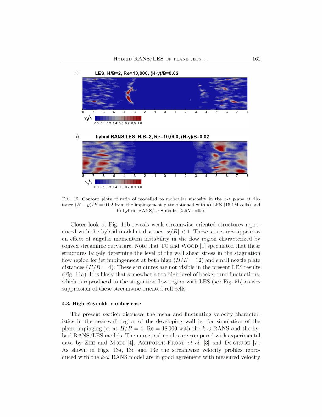
17 Hybrid RANS/LES of plane jets since, as discussed earlier, the mean velocity profiles reproduced with the hybrid model correspond well with the measured velocity profiles (Figs. 6a and 7a). The enhanced turbulence mixing becomes apparent in the near-wall region of the developing wall jet in Fig. 9b from distance x/b = 2 on. Again this is in good agreement with the experimental data shown in Figs. 6b and 7b. LES is not able to capture the final phase of the vortex breakdown process in the nearwall region (Fig. 9c), which results in a too high level of fluctuating velocity components at x/b > 3, for the reasons explained above. The profile of the skin friction coefficient is displayed in Fig. 1. The peak values obtained using RANS and the hybrid model are very similar to the peak value obtained using LES. RANS overpredicts the skin friction coefficient in the developing wall jet region (x/b > 2), owing to a too high momentum near the wall, as shown in Fig. 6a and Fig. 7a. For x/b > 2, the skin friction profile reproduced with the hybrid RANS/LES model falls in between the skin friction profile obtained using RANS and LES. Again, we have to accept that the skin friction profile produced by LES is somewhat too low at distance x/b > 2 due to lack of the grid resolution. Based on Figs. 6a and Fig. 7a, which show that the velocity gradient near the wall obtained by the hybrid model compares very well with the experiments, we can conclude that the skin friction produced by the hybrid model is basically correct (we do not have explicitly the skin friction from the experiments) hybrid RANS/LES LES, dyn. Smag. c f x/b Fig. 1. Skin friction coefficient for H/B = 2, Re = 1. The correspondence between the hybrid RANS/LES and LES model results is further analysed in Fig. 11 showing the contour plots of the Q-criterion (Q = 1/2(Ω ij Ω ij S ij S ij )) in the x-z plane (horizontal plane) at distance (H y)/b =.2 from the impingement plate, obtained with the LES and
18
19
20 162 S. Kubacki et al. a) 1 b).3 U/V x/b=1 Exper, A-F97 Exper, ZM1 hybrid RANS/LES c) 1 Exper, A-F97 d) U/V Exper, ZM1 hybrid RANS/LES x/b= e) f) U/V x/b=7 Exper, A-F97 Exper, ZM1 hybrid RANS/LES <u >/V, (2k/3) 1/2 /V <u >/V, (2k/3) 1/2 /V <u >/V, (2k/3) 1/2 /V Exper, A-F97 hybrid RANS/LES, (RES) hybrid RANS/LES, (TOT) x/b= Exper, A-F97 Exper, ZM1 hybrid RANS/LES, (RES) hybrid RANS/LES, (TOT) x/b= Exper, A-F97 Exper, ZM1 hybrid RANS/LES, (RES) hybrid RANS/LES, (TOT) x/b= Fig. 13. Profiles of mean streamwise velocity (a, c, e) and r.m.s. of streamwise fluctuating velocity component (b, d, f) for simulation of the plane impinging jet at H/D = 4, Re = 18 at various distances from the symmetry plane: a, b) x/b = 1; c, d) x/b = 3 and e, f) x/b = 7. In case of the hybrid model the resolved and total (resolved+modelled) fluctuations are denoted by RES and TOT, respectively.
21 Hybrid RANS/LES of plane jets profiles except very near to the wall where RANS gives a too steep velocity gradient. The near-wall behaviour is better captured with the hybrid RANS/LES model. This is demonstrated in the close-up view of the near-wall region shown in Fig. 13c. Panels b, d and f of Fig. 13 show the comparison between numerical and measured fluctuating streamwise velocity components. The measured wall-normal fluctuating components are not available for this test case, but from Fig. 13b we can speculate that RANS slightly overpredicts the turbulent kinetic energy in the impact zone. The hybrid RANS/LES model gives a too high streamwise fluctuating velocity at y/b = 1 (Fig. 13b), but the near-wall fluctuating velocity is much better captured with the hybrid model further away from the symmetry plane (Figs. 13d and 13f). The hybrid model has a tendency to reproduce a too high level of fluctuating velocity away from the wall ((H y)/b >.2). This might be an indication that the vortex structures produced by the hybrid model are too large there..15 H/B=4, Re=18.1 Exper hybrid RANS/LES c f x/b Fig. 14. Skin friction coefficient for H/B = 4, Re = 18. Figure 14 shows the skin friction coefficient along the impingement plate for H/B = 4, Re = 18. The numerical results are compared with experimental data by Dogruoz [7]. RANS is in error in the transition zone (2 < x/b < 7). With the hybrid model, the deficiency is resolved. Summing up, the hybrid RANS/LES model gives realistic mean and fluctuating velocity profiles along the impingement plate at H/B = 4, Re = 18. The RANS model has the tendency to overpredict the mean velocity gradient in the near-wall region of the developing wall jet. The dip in the skin friction profile is not captured using RANS despite the stress-limiter (Eq. (2.5)). It means
22 164 S. Kubacki et al. that the stress-limiter is not sufficiently strong in the developing wall jet region. The flow details in the transition from the stagnation flow to the developed wall jet region are much better reproduced with the hybrid RANS/LES model than using RANS. 5. Summary The results of simulations of plane impinging jets at different nozzle-plate distances (H/B = 2, 4 and 9.2) and three Reynolds numbers (Re = 1, 18, 2 ) using a k-ω-based hybrid RANS/LES model were presented. The k-ω RANS model has been employed for the low nozzle-plate distance cases (H/B = 2 and 4). Reference results using LES with the dynamic Smagorinsky model were generated for H/B = 2, Re = 1. Overall, good agreement with the experimental data of Zhe and Modi [4] has been obtained with the hybrid RANS/LES model for jet impingement at H/B = 4 and Re = 18 in terms of the mean and fluctuating velocity profiles along the plate. Very good agreement between computed and measured skin friction coefficient along the impingement plate has been obtained with the hybrid RANS/LES model for H/B = 4, Re = 18. The hybrid model results agree also well with the reference LES results in the stagnation flow region (x/b < 2) for H/B = 2, Re = 1. With the RANS model, the stress-limiter is not strong enough, leading to a too large wall shear stress reproduced with RANS along the impingement plate. Acknowledgements The first author acknowledges an international cooperation grant of Ghent University and the support from a research project funded by the Polish National Science Centre (contract number UMO-211/1/B/ST8/7267). References 1. C.V. Tu, D.H. Wood, Wall pressure and shear stress measurements beneath an impinging jet, Experimental Thermal and Fluid Sci., 13, , J. Sakakibara, K. Hishida, M. Maeda, Vortex structure and heat transfer in the stagnation region of an impinging plane jet (simultaneous measurements of velocity and temperature fields by digital particle image velocimetry and laser-induced fluorescence), Int. J. Heat Mass Transfer, 4, , S. Ashforth-Frost, K. Jambunathan, C.F. Whitney, Velocity and turbulence characteristics of a semiconfined orthogonally impinging slot jet, Experimental Thermal and Fluid Science, 14, 6 67, 1997.
23 Hybrid RANS/LES of plane jets J. Zhe, V. Modi, Near wall measurements for a turbulent impinging slot jet, Trans. of the ASME, J. Fluid Eng., 123, , Y. Guo, D.H. Wood, Measurements in the vicinity of a stagnation point, Experimental Thermal and Fluid Science, 25, , V. Narayanan, J. Seyed-Yagoobi, R.H. Page, An experimental study of fluid mechanics and heat transfer in an impinging slot jet flow, Int. J. Heat and Mass Transfer, 47, , M.B. Dogruoz, Experimental and Numerical Investigation of Turbulent Heat Transfer due to Rectangular Impinging Jets, Ph.D. Thesis, the University of Arizona, Tucson, Arizona, J. Senter, C. Solliec, Flow field analysis of a turbulent slot air jet impinging on a moving flat surface, Int. J. Heat Fluid Flow, 28, , T. Cziesla, G. Biswas, H. Chattopadhyay, N.K. Mitra, Large-eddy simulation of flow and heat transfer in an impinging slot jet, Int. J. Heat Mass Transfer, 22, 5 58, F. Beaubert, S. Viazzo, Large eddy simulations of plane turbulent impinging jets at moderate Reynolds numbers, Int. J. Heat Fluid Flow, 24, , M. Tsubokura, T. Kobayashi, N. Taniguchi, W.P. Jones, A numerical study on the eddy structures of impinging jets exited at the inlet, Int. J. Heat Fluid Flow, 24, 5 511, H. Hattori, Y. Nagano, Direct numerical simulation of turbulent heat transfer in plane impinging jet, Int. J. Heat Fluid Flow, 25, , J.A. Fernandez, J.C. Elicer-Cortes, A. Valencia, M. Pavageau, S. Gupta, Comparison of low-cost two-equation turbulence models for prediction flow dynamics in twinjets devices, Int. Commun. Heat Mass Transfer, 34, , J.E. Jaramillo, C.D. Perez-Segarra, I. Rodriguez, A. Oliva, Numerical study of plane and round impinging jets using RANS models, Numer. Heat Transfer Part B, 54, , D.C. Wilcox, Formulation of the k-ω turbulence model revisited, AIAA Journal, 46, , M. Strelets, Detached eddy simulation of massively separated flows, AIAA Paper , J. Fröhlich, D. von Terzi, Hybrid LES/RANS methods for the simulation of turbulent flows, Progress in Aerospace Sciences, 44, , L. Davidson, S.H. Peng, Hybrid LES-RANS modelling: a one-equation SGS model combined with a k-ω model for predicting recirculating flows, Int. J. Numer. Meth. Fluids, 43, , J.C. Kok, H. Dol, H. Oskam, H. van der Ven, Extra-large eddy simulation of massively separated flows, AIAA Paper , J. Yan, C. Mocket, F. Thiele, Investigation of alternative length scale substitutions in detached-eddy simulation, Flow Turbulence and Combustion, 74, 85 12, 25.
24 166 S. Kubacki et al. 21. S. Kubacki, E. Dick, Hybrid RANS/LES of flow and heat transfer in round impinging jets, Int. J. Heat Fluid Flow, 32, , S. Kubacki, E. Dick, Simulation of plane impinging jets with k-ω based hybrid RANS/LES models, Int. J. Heat Fluid Flow, 31, , S. Kubacki, J. Rokicki, E. Dick, Hybrid RANS/LES computation of plane impinging jet flow, Arch. Mech., 63, , A. Scotti, C. Meneveau, D.K. Lilly, Generalized Smagorinsky model for anisotropic grids, Phys. Fluids A, 5, , P.R. Spalart, S. Deck, M.L. Shur, K.D. Squires, M. Strelets, A. Travin, A new version of detached-eddy simulation, resistant to ambiguous grid densities, Theor. Comput. Fluid Dyn., 2, , D.C. Wilcox, Turbulence Modeling for CFD, 2nd ed., DCW Industries Inc., La Canada CA, F. Mathey, D. Cokljat, J.P. Bertoglio, E. Sergent, Assessment of the vortex method for Large Eddy Simulation inlet conditions, Progress Comput. Fluid Dynamics, 6, 58 67, S. Kubacki, E. Dick, Convective heat transfer prediction for an axisymmetric jet impinging onto a flat plate with an improved k-ω model, Int. J. Numer. Methods in Heat and Fluid Flow, 19, , B. Chaouat, R. Schiestel, A new partially integrated transport model for subgrid-scale stresses and dissipation rate for turbulent developing flows, Phys. Fluids, 17, 6516, 25. Received November 14, 212; revised version February 4, 213.
Hybrid RANS/LES computation of plane impinging jet flow
 Arch. Mech., 63, 2, pp. 117 136, Warszawa 2011 Hybrid RANS/LES computation of plane impinging jet flow S. KUBACKI 1,2), J. ROKICKI 1), E. DICK 2) 1) Institute of Aeronautics and Applied Mechanics Warsaw
CONFERENCE PROCEEDINGS
 Ecole Royale Militaire Avenue de la Renaissance 30 B-1000 Bruxelles www.rma.ac.be Koninklike Militaire School Renaissancelaan 30 B-1000 Brussel CONFERENCE PROCEEDINGS 9-10 May 2012 ROYAL MILITARY ACADEMY
Turbulent Boundary Layers & Turbulence Models. Lecture 09
 Turbulent Boundary Layers & Turbulence Models Lecture 09 The turbulent boundary layer In turbulent flow, the boundary layer is defined as the thin region on the surface of a body in which viscous effects
Optimizing calculation costs of tubulent flows with RANS/LES methods
 Optimizing calculation costs of tubulent flows with RANS/LES methods Investigation in separated flows C. Friess, R. Manceau Dpt. Fluid Flow, Heat Transfer, Combustion Institute PPrime, CNRS University
NEAR-WALL MODELING OF LES FOR NON-EQUILIBRIUM TURBULENT FLOWS IN AN INCLINED IMPINGING JET WITH MODERATE RE-NUMBER
 6th European Conference on Computational Mechanics (ECCM 6) 7th European Conference on Computational Fluid Dynamics (ECFD 7) 1115 June 2018, Glasgow, UK NEAR-WALL MODELING OF LES FOR NON-EQUILIBRIUM TURBULENT
RECONSTRUCTION OF TURBULENT FLUCTUATIONS FOR HYBRID RANS/LES SIMULATIONS USING A SYNTHETIC-EDDY METHOD
 RECONSTRUCTION OF TURBULENT FLUCTUATIONS FOR HYBRID RANS/LES SIMULATIONS USING A SYNTHETIC-EDDY METHOD N. Jarrin 1, A. Revell 1, R. Prosser 1 and D. Laurence 1,2 1 School of MACE, the University of Manchester,
An evaluation of a conservative fourth order DNS code in turbulent channel flow
 Center for Turbulence Research Annual Research Briefs 2 2 An evaluation of a conservative fourth order DNS code in turbulent channel flow By Jessica Gullbrand. Motivation and objectives Direct numerical
Turbulence Modeling I!
 Outline! Turbulence Modeling I! Grétar Tryggvason! Spring 2010! Why turbulence modeling! Reynolds Averaged Numerical Simulations! Zero and One equation models! Two equations models! Model predictions!
arxiv: v1 [physics.flu-dyn] 4 Aug 2014
![arxiv: v1 [physics.flu-dyn] 4 Aug 2014](/thumbs/83/87633147.jpg "arxiv: v1 [physics.flu-dyn] 4 Aug 2014") A hybrid RANS/LES framework to investigate spatially developing turbulent boundary layers arxiv:1408.1060v1 [physics.flu-dyn] 4 Aug 2014 Sunil K. Arolla a,1, a Sibley School of Mechanical and Aerospace
A hybrid RANS/LES framework to investigate spatially developing turbulent boundary layers arxiv:1408.1060v1 [physics.flu-dyn] 4 Aug 2014 Sunil K. Arolla a,1, a Sibley School of Mechanical and Aerospace
Numerical Methods in Aerodynamics. Turbulence Modeling. Lecture 5: Turbulence modeling
 Turbulence Modeling Niels N. Sørensen Professor MSO, Ph.D. Department of Civil Engineering, Alborg University & Wind Energy Department, Risø National Laboratory Technical University of Denmark 1 Outline
Numerical simulations of heat transfer in plane channel flow
 Numerical simulations of heat transfer in plane channel flow Najla EL GHARBI 1, 3, a, Rafik ABSI 2, b and Ahmed BENZAOUI 3, c 1 Renewable Energy Development Center, BP 62 Bouzareah 163 Algiers, Algeria
Resolving the dependence on free-stream values for the k-omega turbulence model
 Resolving the dependence on free-stream values for the k-omega turbulence model J.C. Kok Resolving the dependence on free-stream values for the k-omega turbulence model J.C. Kok This report is based on
Large eddy simulation of turbulent flow over a backward-facing step: effect of inflow conditions
 June 30 - July 3, 2015 Melbourne, Australia 9 P-26 Large eddy simulation of turbulent flow over a backward-facing step: effect of inflow conditions Jungwoo Kim Department of Mechanical System Design Engineering
On the feasibility of merging LES with RANS for the near-wall region of attached turbulent flows
 Center for Turbulence Research Annual Research Briefs 1998 267 On the feasibility of merging LES with RANS for the near-wall region of attached turbulent flows By Jeffrey S. Baggett 1. Motivation and objectives
RANS-LES inlet boundary condition for aerodynamic and aero-acoustic. acoustic applications. Fabrice Mathey Davor Cokljat Fluent Inc.
 RANS-LES inlet boundary condition for aerodynamic and aero-acoustic acoustic applications Fabrice Mathey Davor Cokljat Fluent Inc. Presented by Fredrik Carlsson Fluent Sweden ZONAL MULTI-DOMAIN RANS/LES
LARGE EDDY SIMULATION OF MASS TRANSFER ACROSS AN AIR-WATER INTERFACE AT HIGH SCHMIDT NUMBERS
 The 6th ASME-JSME Thermal Engineering Joint Conference March 6-, 3 TED-AJ3-3 LARGE EDDY SIMULATION OF MASS TRANSFER ACROSS AN AIR-WATER INTERFACE AT HIGH SCHMIDT NUMBERS Akihiko Mitsuishi, Yosuke Hasegawa,
Comparison of Turbulence Models in the Flow over a Backward-Facing Step Priscila Pires Araujo 1, André Luiz Tenório Rezende 2
 Comparison of Turbulence Models in the Flow over a Backward-Facing Step Priscila Pires Araujo 1, André Luiz Tenório Rezende 2 Department of Mechanical and Materials Engineering, Military Engineering Institute,
On the transient modelling of impinging jets heat transfer. A practical approach
 Turbulence, Heat and Mass Transfer 7 2012 Begell House, Inc. On the transient modelling of impinging jets heat transfer. A practical approach M. Bovo 1,2 and L. Davidson 1 1 Dept. of Applied Mechanics,
Hybrid RANS/LES employing Interface Condition with Turbulent Structure
 Turbulence, Heat and Mass Transfer 4, pp. 689696 K. Hanjalić, Y. Nagano and M. Tummers (Editors) c 23 Begell House, Inc. Hybrid RANS/LES employing Interface Condition with Turbulent Structure S. Dahlström
A Computational Investigation of a Turbulent Flow Over a Backward Facing Step with OpenFOAM
 206 9th International Conference on Developments in esystems Engineering A Computational Investigation of a Turbulent Flow Over a Backward Facing Step with OpenFOAM Hayder Al-Jelawy, Stefan Kaczmarczyk
Calculations on a heated cylinder case
 Calculations on a heated cylinder case J. C. Uribe and D. Laurence 1 Introduction In order to evaluate the wall functions in version 1.3 of Code Saturne, a heated cylinder case has been chosen. The case
There are no simple turbulent flows
 Turbulence 1 There are no simple turbulent flows Turbulent boundary layer: Instantaneous velocity field (snapshot) Ref: Prof. M. Gad-el-Hak, University of Notre Dame Prediction of turbulent flows standard
Boundary-Layer Theory
 Hermann Schlichting Klaus Gersten Boundary-Layer Theory With contributions from Egon Krause and Herbert Oertel Jr. Translated by Katherine Mayes 8th Revised and Enlarged Edition With 287 Figures and 22
WALL ROUGHNESS EFFECTS ON SHOCK BOUNDARY LAYER INTERACTION FLOWS
 ISSN (Online) : 2319-8753 ISSN (Print) : 2347-6710 International Journal of Innovative Research in Science, Engineering and Technology An ISO 3297: 2007 Certified Organization, Volume 2, Special Issue
INVESTIGATION OF THE FLOW OVER AN OSCILLATING CYLINDER WITH THE VERY LARGE EDDY SIMULATION MODEL
 ECCOMAS Congress 2016 VII European Congress on Computational Methods in Applied Sciences and Engineering M. Papadrakakis, V. Papadopoulos, G. Stefanou, V. Plevris (eds.) Crete Island, Greece, 5 10 June
A NOVEL VLES MODEL FOR TURBULENT FLOW SIMULATIONS
 June 30 - July 3, 2015 Melbourne, Australia 9 7B-4 A NOVEL VLES MODEL FOR TURBULENT FLOW SIMULATIONS C.-Y. Chang, S. Jakirlić, B. Krumbein and C. Tropea Institute of Fluid Mechanics and Aerodynamics /
RANS simulations of rotating flows
 Center for Turbulence Research Annual Research Briefs 1999 257 RANS simulations of rotating flows By G. Iaccarino, A. Ooi, B. A. Pettersson Reif AND P. Durbin 1. Motivation and objectives Numerous experimental
Atmospheric Boundary Layer Studies with Unified RANS-LES and Dynamic LES Methods
 5st AIAA Aerospace Sciences Meeting including the New Horizons Forum and Aerospace Exposition 7 - January 23, Grapevine (Dallas/Ft. Worth Region), Texas AIAA 23-747 Atmospheric Boundary Layer Studies with
Turbulent eddies in the RANS/LES transition region
 Turbulent eddies in the RANS/LES transition region Ugo Piomelli Senthil Radhakrishnan Giuseppe De Prisco University of Maryland College Park, MD, USA Research sponsored by the ONR and AFOSR Outline Motivation
DEVELOPMENT OF CFD MODEL FOR A SWIRL STABILIZED SPRAY COMBUSTOR
 DRAFT Proceedings of ASME IMECE: International Mechanical Engineering Conference & Exposition Chicago, Illinois Nov. 5-10, 2006 IMECE2006-14867 DEVELOPMENT OF CFD MODEL FOR A SWIRL STABILIZED SPRAY COMBUSTOR
Masters in Mechanical Engineering. Problems of incompressible viscous flow. 2µ dx y(y h)+ U h y 0 < y < h,
+ U h y 0 < y < h,") Masters in Mechanical Engineering Problems of incompressible viscous flow 1. Consider the laminar Couette flow between two infinite flat plates (lower plate (y = 0) with no velocity and top plate (y =
Masters in Mechanical Engineering Problems of incompressible viscous flow 1. Consider the laminar Couette flow between two infinite flat plates (lower plate (y = 0) with no velocity and top plate (y =
Periodic planes v i+1 Top wall u i. Inlet. U m y. Jet hole. Figure 2. Schematic of computational domain.
 Flow Characterization of Inclined Jet in Cross Flow for Thin Film Cooling via Large Eddy Simulation Naqavi, I.Z. 1, Savory, E. 2 and Martinuzzi, R. J. 3 1,2 The Univ. of Western Ontario, Dept. of Mech.
Introduction to Turbulence and Turbulence Modeling
 Introduction to Turbulence and Turbulence Modeling Part I Venkat Raman The University of Texas at Austin Lecture notes based on the book Turbulent Flows by S. B. Pope Turbulent Flows Turbulent flows Commonly
Numerical simulation of flow past a circular base on PANS methods
 IOP Conference Series: Materials Science and Engineering PAPER OPEN ACCESS Numerical simulation of flow past a circular base on PANS methods To cite this article: J T Liu et al 016 IOP Conf. Ser.: Mater.
2.3 The Turbulent Flat Plate Boundary Layer
 Canonical Turbulent Flows 19 2.3 The Turbulent Flat Plate Boundary Layer The turbulent flat plate boundary layer (BL) is a particular case of the general class of flows known as boundary layer flows. The
The Effect of Endplates on Rectangular Jets of Different Aspect Ratios
 The Effect of Endplates on Rectangular Jets of Different Aspect Ratios M. Alnahhal *, Th. Panidis Laboratory of Applied Thermodynamics, Mechanical Engineering and Aeronautics Department, University of
NUMERICAL SIMULATION OF TRANSITIONAL FLOWS WITH LAMINAR KINETIC ENERGY
 Engineering MECHANICS, Vol. 20, 2013, No. 5, p. 379 388 379 NUMERICAL SIMULATION OF TRANSITIONAL FLOWS WITH LAMINAR KINETIC ENERGY JiříFürst* The article deals with the numerical solution of transitional
A Solution Method for the Reynolds-Averaged Navier-Stokes Equation
 A Solution Method for the Reynolds-Averaged Navier-Stokes Equation T.-W. Lee Mechanical and Aerospace Engineering, Arizona State University, Tempe, AZ, 8587 Abstract- Navier-Stokes equations are difficult
CFD Analysis for Thermal Behavior of Turbulent Channel Flow of Different Geometry of Bottom Plate
 International Journal Of Engineering Research And Development e-issn: 2278-067X, p-issn: 2278-800X, www.ijerd.com Volume 13, Issue 9 (September 2017), PP.12-19 CFD Analysis for Thermal Behavior of Turbulent
Prediction of unsteady heat transfer from a cylinder in crossflow
 Center for Turbulence Research Proceedings of the Summer Program 202 07 Prediction of unsteady heat transfer from a cylinder in crossflow By S. T. Bose, B. C. Wang AND M. Saeedi The accuracy of a tensorial
A combined application of the integral wall model and the rough wall rescaling-recycling method
 AIAA 25-299 A combined application of the integral wall model and the rough wall rescaling-recycling method X.I.A. Yang J. Sadique R. Mittal C. Meneveau Johns Hopkins University, Baltimore, MD, 228, USA
Near-wall Reynolds stress modelling for RANS and hybrid RANS/LES methods
 Platzhalter für Bild, Bild auf Titelfolie hinter das Logo einsetzen Near-wall Reynolds stress modelling for RANS and hybrid RANS/LES methods Axel Probst (now at: C 2 A 2 S 2 E, DLR Göttingen) René Cécora,
COMPUTATIONAL FLUID DYNAMICS ANALYSIS OF A V-RIB WITH GAP ROUGHENED SOLAR AIR HEATER
 THERMAL SCIENCE: Year 2018, Vol. 22, No. 2, pp. 963-972 963 COMPUTATIONAL FLUID DYNAMICS ANALYSIS OF A V-RIB WITH GAP ROUGHENED SOLAR AIR HEATER by Jitesh RANA, Anshuman SILORI, Rajesh MAITHANI *, and
DNS STUDY OF TURBULENT HEAT TRANSFER IN A SPANWISE ROTATING SQUARE DUCT
 10 th International Symposium on Turbulence and Shear Flow Phenomena (TSFP10), Chicago, USA, July, 2017 DNS STUDY OF TURBULENT HEAT TRANSFER IN A SPANWISE ROTATING SQUARE DUCT Bing-Chen Wang Department
COMPARISON OF DIFFERENT SUBGRID TURBULENCE MODELS AND BOUNDARY CONDITIONS FOR LARGE-EDDY-SIMULATIONS OF ROOM AIR FLOWS.
 7 TH INTRNATINAL CNFRNC N AIR DISTRIBTIN IN RMS, RMVNT 2 pp. 31-36 CMPARISN F DIFFRNT SBGRID TRBLNC MDLS AND BNDARY CNDITINS FR LARG-DDY-SIMLATINS F RM AIR FLWS. D. Müller 1, L. Davidson 2 1 Lehrstuhl
Computers and Mathematics with Applications. Investigation of the LES WALE turbulence model within the lattice Boltzmann framework
 Computers and Mathematics with Applications 59 (2010) 2200 2214 Contents lists available at ScienceDirect Computers and Mathematics with Applications journal homepage: www.elsevier.com/locate/camwa Investigation
The Role of Splatting Effect in High Schmidt Number Turbulent Mass Transfer Across an Air-Water Interface
 Turbulence, Heat and Mass Transfer 4 K. Hanjalic, Y. Nagano and M. Tummers (Editors) 3 Begell House, Inc. The Role of Splatting Effect in High Schmidt Number Turbulent Mass Transfer Across an Air-Water
Uncertainty quantification for RANS simulation of flow over a wavy wall
 Uncertainty quantification for RANS simulation of flow over a wavy wall Catherine Gorlé 1,2,3, Riccardo Rossi 1,4, and Gianluca Iaccarino 1 1 Center for Turbulence Research, Stanford University, Stanford,
CFD in Heat Transfer Equipment Professor Bengt Sunden Division of Heat Transfer Department of Energy Sciences Lund University
 CFD in Heat Transfer Equipment Professor Bengt Sunden Division of Heat Transfer Department of Energy Sciences Lund University email: bengt.sunden@energy.lth.se CFD? CFD = Computational Fluid Dynamics;
SHEAR-LAYER MANIPULATION OF BACKWARD-FACING STEP FLOW WITH FORCING: A NUMERICAL STUDY
 SHEAR-LAYER MANIPULATION OF BACKWARD-FACING STEP FLOW WITH FORCING: A NUMERICAL STUDY Shia-Hui Peng Swedish Defence Research Agency, FOI, Sweden peng@foi.se 1 Introduction By means of experimental and
Velocity Fluctuations in a Particle-Laden Turbulent Flow over a Backward-Facing Step
 Copyright c 2004 Tech Science Press CMC, vol.1, no.3, pp.275-288, 2004 Velocity Fluctuations in a Particle-Laden Turbulent Flow over a Backward-Facing Step B. Wang 1, H.Q. Zhang 1, C.K. Chan 2 and X.L.
Available online at ScienceDirect. Procedia Engineering 79 (2014 ) 49 54
 49 54") Available online at www.sciencedirect.com ScienceDirect Procedia Engineering 79 (2014 ) 49 54 37th National Conference on Theoretical and Applied Mechanics (37th NCTAM 2013) & The 1st International Conference
Available online at www.sciencedirect.com ScienceDirect Procedia Engineering 79 (2014 ) 49 54 37th National Conference on Theoretical and Applied Mechanics (37th NCTAM 2013) & The 1st International Conference
A Low Reynolds Number Variant of Partially-Averaged Navier-Stokes Model for Turbulence
 Int. J. Heat Fluid Flow, Vol., pp. 65-669 (), doi:.6/j.ijheatfluidflow... A Low Reynolds Number Variant of Partially-Averaged Navier-Stokes Model for Turbulence J.M. Ma,, S.-H. Peng,, L. Davidson, and
A TURBULENT HEAT FLUX TWO EQUATION θ 2 ε θ CLOSURE BASED ON THE V 2F TURBULENCE MODEL
 TASK QUARTERLY 7 No 3 (3), 375 387 A TURBULENT HEAT FLUX TWO EQUATION θ ε θ CLOSURE BASED ON THE V F TURBULENCE MODEL MICHAŁ KARCZ AND JANUSZ BADUR Institute of Fluid-Flow Machinery, Polish Academy of
Turbulence Laboratory
 Objective: CE 319F Elementary Mechanics of Fluids Department of Civil, Architectural and Environmental Engineering The University of Texas at Austin Turbulence Laboratory The objective of this laboratory
Probability density function (PDF) methods 1,2 belong to the broader family of statistical approaches
 methods 1,2 belong to the broader family of statistical approaches") Joint probability density function modeling of velocity and scalar in turbulence with unstructured grids arxiv:6.59v [physics.flu-dyn] Jun J. Bakosi, P. Franzese and Z. Boybeyi George Mason University,
Joint probability density function modeling of velocity and scalar in turbulence with unstructured grids arxiv:6.59v [physics.flu-dyn] Jun J. Bakosi, P. Franzese and Z. Boybeyi George Mason University,
Heat Transfer from An Impingement Jet onto A Heated Half-Prolate Spheroid Attached to A Heated Flat Plate
 1 nd International Conference on Environment and Industrial Innovation IPCBEE vol.35 (1) (1) IACSIT Press, Singapore Heat Transfer from An Impingement Jet onto A Heated Half-Prolate Spheroid Attached to
Effect of near-wall treatments on airflow simulations
 Proceedings of 29 International Conference on Computational Methods for Energy Engineering and Environment: ICCM3E. Sousse, Tunisia, 2-22 November, 29, pp. Effect of near-wall treatments on airflow simulations
Validation 3. Laminar Flow Around a Circular Cylinder
 Validation 3. Laminar Flow Around a Circular Cylinder 3.1 Introduction Steady and unsteady laminar flow behind a circular cylinder, representing flow around bluff bodies, has been subjected to numerous
Divergence free synthetic eddy method for embedded LES inflow boundary condition
 R. Poletto*, A. Revell, T. Craft, N. Jarrin for embedded LES inflow boundary condition University TSFP Ottawa 28-31/07/2011 *email: ruggero.poletto@postgrad.manchester.ac.uk 1 / 19 SLIDES OVERVIEW 1 Introduction
LES/RANS Modeling of Turbulent Mixing in a Jet in Crossflow at Low Velocity Ratios
 LES/RANS Modeling of Turbulent Mixing in a Jet in Crossflow at Low Velocity Ratios Juliane Prause, Yeshaswini Emmi, Berthold Noll and Manfred Aigner German Aerospace Center (DLR), Stuttgart, Germany Turbulent
Engineering. Spring Department of Fluid Mechanics, Budapest University of Technology and Economics. Large-Eddy Simulation in Mechanical
 Outline Geurts Book Department of Fluid Mechanics, Budapest University of Technology and Economics Spring 2013 Outline Outline Geurts Book 1 Geurts Book Origin This lecture is strongly based on the book:
arxiv: v1 [physics.flu-dyn] 11 Oct 2012
![arxiv: v1 [physics.flu-dyn] 11 Oct 2012](/thumbs/94/118739408.jpg "arxiv: v1 [physics.flu-dyn] 11 Oct 2012") Low-Order Modelling of Blade-Induced Turbulence for RANS Actuator Disk Computations of Wind and Tidal Turbines Takafumi Nishino and Richard H. J. Willden ariv:20.373v [physics.flu-dyn] Oct 202 Abstract
Low-Order Modelling of Blade-Induced Turbulence for RANS Actuator Disk Computations of Wind and Tidal Turbines Takafumi Nishino and Richard H. J. Willden ariv:20.373v [physics.flu-dyn] Oct 202 Abstract
The mean shear stress has both viscous and turbulent parts. In simple shear (i.e. U / y the only non-zero mean gradient):
:") 8. TURBULENCE MODELLING 1 SPRING 2019 8.1 Eddy-viscosity models 8.2 Advanced turbulence models 8.3 Wall boundary conditions Summary References Appendix: Derivation of the turbulent kinetic energy equation
8. TURBULENCE MODELLING 1 SPRING 2019 8.1 Eddy-viscosity models 8.2 Advanced turbulence models 8.3 Wall boundary conditions Summary References Appendix: Derivation of the turbulent kinetic energy equation
International Journal of Scientific & Engineering Research, Volume 6, Issue 5, May ISSN
 International Journal of Scientific & Engineering Research, Volume 6, Issue 5, May-2015 28 CFD BASED HEAT TRANSFER ANALYSIS OF SOLAR AIR HEATER DUCT PROVIDED WITH ARTIFICIAL ROUGHNESS Vivek Rao, Dr. Ajay
Turbulence: Basic Physics and Engineering Modeling
 DEPARTMENT OF ENERGETICS Turbulence: Basic Physics and Engineering Modeling Numerical Heat Transfer Pietro Asinari, PhD Spring 2007, TOP UIC Program: The Master of Science Degree of the University of Illinois
ENGINEERING MECHANICS 2012 pp Svratka, Czech Republic, May 14 17, 2012 Paper #195
 . 18 m 2012 th International Conference ENGINEERING MECHANICS 2012 pp. 309 315 Svratka, Czech Republic, May 14 17, 2012 Paper #195 NUMERICAL SIMULATION OF TRANSITIONAL FLOWS WITH LAMINAR KINETIC ENERGY
A dynamic global-coefficient subgrid-scale eddy-viscosity model for large-eddy simulation in complex geometries
 Center for Turbulence Research Annual Research Briefs 2006 41 A dynamic global-coefficient subgrid-scale eddy-viscosity model for large-eddy simulation in complex geometries By D. You AND P. Moin 1. Motivation
Model Studies on Slag-Metal Entrainment in Gas Stirred Ladles
 Model Studies on Slag-Metal Entrainment in Gas Stirred Ladles Anand Senguttuvan Supervisor Gordon A Irons 1 Approach to Simulate Slag Metal Entrainment using Computational Fluid Dynamics Introduction &
Turbulence - Theory and Modelling GROUP-STUDIES:
 Lund Institute of Technology Department of Energy Sciences Division of Fluid Mechanics Robert Szasz, tel 046-0480 Johan Revstedt, tel 046-43 0 Turbulence - Theory and Modelling GROUP-STUDIES: Turbulence
Explicit algebraic Reynolds stress models for boundary layer flows
 1. Explicit algebraic models Two explicit algebraic models are here compared in order to assess their predictive capabilities in the simulation of boundary layer flow cases. The studied models are both
DETACHED-EDDY SIMULATION OF FLOW PAST A BACKWARD-FACING STEP WITH A HARMONIC ACTUATION
 DETACHED-EDDY SIMULATION OF FLOW PAST A BACKWARD-FACING STEP WITH A HARMONIC ACTUATION Liang Wang*, Ruyun Hu*, Liying Li*, Song Fu* *School of Aerospace Engineering, Tsinghua University, Beijing 100084,
COMMUTATION ERRORS IN PITM SIMULATION
 COMMUTATION ERRORS IN PITM SIMULATION B. Chaouat ONERA, 93 Châtillon, France Bruno.Chaouat@onera.fr Introduction Large eddy simulation is a promising route. This approach has been largely developed in
Simulating Drag Crisis for a Sphere Using Skin Friction Boundary Conditions
 Simulating Drag Crisis for a Sphere Using Skin Friction Boundary Conditions Johan Hoffman May 14, 2006 Abstract In this paper we use a General Galerkin (G2) method to simulate drag crisis for a sphere,
DNS, LES, and wall-modeled LES of separating flow over periodic hills
 Center for Turbulence Research Proceedings of the Summer Program 4 47 DNS, LES, and wall-modeled LES of separating flow over periodic hills By P. Balakumar, G. I. Park AND B. Pierce Separating flow in
compression corner flows with high deflection angle, for example, the method cannot predict the location
 4nd AIAA Aerospace Sciences Meeting and Exhibit 5-8 January 4, Reno, Nevada Modeling the effect of shock unsteadiness in shock-wave/ turbulent boundary layer interactions AIAA 4-9 Krishnendu Sinha*, Krishnan
Explicit algebraic Reynolds stress models for internal flows
 5. Double Circular Arc (DCA) cascade blade flow, problem statement The second test case deals with a DCA compressor cascade, which is considered a severe challenge for the CFD codes, due to the presence
Computation for the Backward Facing Step Test Case with an Open Source Code
 Computation for the Backward Facing Step Test Case with an Open Source Code G.B. Deng Equipe de Modélisation Numérique Laboratoire de Mécanique des Fluides Ecole Centrale de Nantes 1 Rue de la Noë, 44321
EVALUATION OF THE SST-SAS MODEL: CHANNEL FLOW, ASYMMETRIC DIFFUSER AND AXI-SYMMETRIC HILL
 st line after Eq. 4 corrected European Conference on Computational Fluid Dynamics ECCOMAS CFD 6 P. Wesseling, E. Oñate and J. Périaux (Eds) c TU Delft, The Netherlands, 6 EVALUATION OF THE SST-SAS MODEL:
NONLINEAR FEATURES IN EXPLICIT ALGEBRAIC MODELS FOR TURBULENT FLOWS WITH ACTIVE SCALARS
 June - July, 5 Melbourne, Australia 9 7B- NONLINEAR FEATURES IN EXPLICIT ALGEBRAIC MODELS FOR TURBULENT FLOWS WITH ACTIVE SCALARS Werner M.J. Lazeroms () Linné FLOW Centre, Department of Mechanics SE-44
Numerical investigation of the flow instabilities in centrifugal fan
 Proceedings of the 4th WSEAS International Conference on Fluid Mechanics and Aerodynamics, Elounda, Greece, August 21-23, 26 (pp282-288) Numerical investigation of the flow instabilities in centrifugal
+ = + t x x x x u. The standard Smagorinsky model has been used in the work to provide the closure for the subgridscale eddy viscosity in (2):
:") International Conference on Methods of Aerophysical Research, ICMAR 008 LARGE EDDY SIMULATION OF TURBULENT ROUND IMPINGING JET B.B. Ilyushin, D.V. Krasinsky Kutateladze Institute of Thermophysics SB RAS
International Conference on Methods of Aerophysical Research, ICMAR 008 LARGE EDDY SIMULATION OF TURBULENT ROUND IMPINGING JET B.B. Ilyushin, D.V. Krasinsky Kutateladze Institute of Thermophysics SB RAS
CHAPTER 7 NUMERICAL MODELLING OF A SPIRAL HEAT EXCHANGER USING CFD TECHNIQUE
 CHAPTER 7 NUMERICAL MODELLING OF A SPIRAL HEAT EXCHANGER USING CFD TECHNIQUE In this chapter, the governing equations for the proposed numerical model with discretisation methods are presented. Spiral
VALIDATION OF REYNOLDS AVERAGED MODEL AND LARGE EDDY SIMULATION IN ACTUAL FLOOR HEATING ROOM. Hiroki Ono 1 and Koji Sakai 1
 Proceedings of Building Simulation 11: VALDATON OF RYNOLDS AVRAD MODL AND LAR DDY SMULATON N ACTUAL FLOOR HATN ROOM Hiroki Ono 1 and Koji Sakai 1 1 School of Science and Technology, Meiji University, Kawasaki,
Numerical Simulation of a Blunt Airfoil Wake
 6th Australasian Fluid Mechanics Conference Crown Plaza, Gold Coast, Australia 2-7 December 7 Numerical Simulation of a Blunt Airfoil Wake C.J. Doolan School of Mechanical Engineering University of Adelaide,
Numerical analysis of fluid flow and heat transfer in 2D sinusoidal wavy channel
 Numerical analysis of fluid flow and heat transfer in 2D sinusoidal wavy channel Arunanshu Chakravarty 1* 1 CTU in Prague, Faculty of Mechanical Engineering, Department of Process Engineering,Technická
Numerical investigation of swirl flow inside a supersonic nozzle
 Advances in Fluid Mechanics IX 131 Numerical investigation of swirl flow inside a supersonic nozzle E. Eslamian, H. Shirvani & A. Shirvani Faculty of Science and Technology, Anglia Ruskin University, UK
Zonal hybrid RANS-LES modeling using a Low-Reynolds-Number k ω approach
 Zonal hybrid RANS-LES modeling using a Low-Reynolds-Number k ω approach S. Arvidson 1,2, L. Davidson 1, S.-H. Peng 1,3 1 Chalmers University of Technology 2 SAAB AB, Aeronautics 3 FOI, Swedish Defence
Comparison of two equations closure turbulence models for the prediction of heat and mass transfer in a mechanically ventilated enclosure
 Proceedings of 4 th ICCHMT May 17-0, 005, Paris-Cachan, FRANCE 381 Comparison of two equations closure turbulence models for the prediction of heat and mass transfer in a mechanically ventilated enclosure
LES modeling of heat and mass transfer in turbulent recirculated flows E. Baake 1, B. Nacke 1, A. Umbrashko 2, A. Jakovics 2
 MAGNETOHYDRODYNAMICS Vol. 00 (1964), No. 00, pp. 1 5 LES modeling of heat and mass transfer in turbulent recirculated flows E. Baake 1, B. Nacke 1, A. Umbrashko 2, A. Jakovics 2 1 Institute for Electrothermal
Numerical Investigation of the Transonic Base Flow of A Generic Rocket Configuration
 1 Numerical Investigation of the Transonic Base Flow of A Generic Rocket Configuration A. Henze, C. Glatzer, M. Meinke, W. Schröder Institute of Aerodynamics, RWTH Aachen University, Germany March 21,
Direct Numerical Simulations of Transitional Flow in Turbomachinery
 Direct Numerical Simulations of Transitional Flow in Turbomachinery J.G. Wissink and W. Rodi Institute for Hydromechanics University of Karlsruhe Unsteady transitional flow over turbine blades Periodic
Publication 97/2. An Introduction to Turbulence Models. Lars Davidson, lada
 ublication 97/ An ntroduction to Turbulence Models Lars Davidson http://www.tfd.chalmers.se/ lada Department of Thermo and Fluid Dynamics CHALMERS UNVERSTY OF TECHNOLOGY Göteborg Sweden November 3 Nomenclature
Hybrid LES RANS Method Based on an Explicit Algebraic Reynolds Stress Model
 Hybrid RANS Method Based on an Explicit Algebraic Reynolds Stress Model Benoit Jaffrézic, Michael Breuer and Antonio Delgado Institute of Fluid Mechanics, LSTM University of Nürnberg bjaffrez/breuer@lstm.uni-erlangen.de
Laminar Flow. Chapter ZERO PRESSURE GRADIENT
 Chapter 2 Laminar Flow 2.1 ZERO PRESSRE GRADIENT Problem 2.1.1 Consider a uniform flow of velocity over a flat plate of length L of a fluid of kinematic viscosity ν. Assume that the fluid is incompressible
Flow Structure Investigations in a "Tornado" Combustor
 Flow Structure Investigations in a "Tornado" Combustor Igor Matveev Applied Plasma Technologies, Falls Church, Virginia, 46 Serhiy Serbin National University of Shipbuilding, Mikolayiv, Ukraine, 545 Thomas
Numerical modeling of complex turbulent flows
 ISTP-16, 5, PRAGUE 16 TH INTERNATIONAL SYMPOSIUM ON TRANSPORT PHENOMENA Numerical modeling of complex turbulent flows Karel Kozel Petr Louda Jaromír Příhoda Dept. of Technical Mathematics CTU Prague, Karlovo
AER1310: TURBULENCE MODELLING 1. Introduction to Turbulent Flows C. P. T. Groth c Oxford Dictionary: disturbance, commotion, varying irregularly
 1. Introduction to Turbulent Flows Coverage of this section: Definition of Turbulence Features of Turbulent Flows Numerical Modelling Challenges History of Turbulence Modelling 1 1.1 Definition of Turbulence
The effect of geometric parameters on the head loss factor in headers
 Fluid Structure Interaction V 355 The effect of geometric parameters on the head loss factor in headers A. Mansourpour & S. Shayamehr Mechanical Engineering Department, Azad University of Karaj, Iran Abstract
An alternative turbulent heat flux modelling for gas turbine cooling application
 TRANSACTIONS OF THE INSTITUTE OF FLUID-FLOW MACHINERY No. 3, 23, 2-?? MICHAŁ KARCZ and JANUSZ BADUR An alternative turbulent heat flux modelling for gas turbine cooling application Institute of Fluid-Flow