CHAPTER 12 STRUCTURES AND PROPERTIES OF CERAMICS PROBLEM SOLUTIONS
|
|
|
- Julian Walker
- 5 years ago
- Views:
Transcription
1 CHAPTER 12 STRUCTURES AND PROPERTIES OF CERAMICS PROBLEM SOLUTIONS Crystal Structures 12.1 For a ceramic compound, what are the two characteristics of the component ions that determine the crystal structure? The two characteristics of component ions that determine the crystal structure of a ceramic compound are: 1) the magnitude of the electrical charge on each ion, and 2) the relative sizes of the cations and anions.
2 12.2 Show that the minimum cation-to-anion radius ratio for a coordination number of 4 is In this problem we are asked to show that the minimum cation-to-anion radius ratio for a coordination number of four is If lines are drawn from the centers of the anions, then a tetrahedron is formed. The tetrahedron may be inscribed within a cube as shown below. The spheres at the apexes of the tetrahedron are drawn at the corners of the cube, and designated as positions A, B, C, and D. (These are reduced in size for the sake of clarity.) The cation resides at the center of the cube, which is designated as point E. Let us now express the cation and anion radii in terms of the cube edge length, designated as a. The spheres located at positions A and B touch each other along the bottom face diagonal. Thus, AB 2r A But (AB) 2 a 2 + a 2 2a 2 or AB a 2 2r A And a 2r A 2
3 There will also be an anion located at the corner, point F (not drawn), and the cube diagonal AEF will be related to the ionic radii as AEF 2(r A + r C ) (The line AEF has not been drawn to avoid confusion.) From the triangle ABF (AB) 2 + (FB) 2 (AEF) 2 But, and FB a 2r A 2 AB 2r A from above. Thus, (2r A ) 2 + 2r 2 A 2 [ 2(r A + r C )] 2 Solving for the r C /r A ratio leads to r C r A
4 12. Show that the minimum cation-to-anion radius ratio for a coordination number of 6 is [Hint: Use the NaCl crystal structure (Figure 12.2), and assume that anions and cations are just touching along cube edges and across face diagonals.] This problem asks us to show that the minimum cation-to-anion radius ratio for a coordination number of 6 is (using the rock salt crystal structure). Below is shown one of the faces of the rock salt crystal structure in which anions and cations just touch along the edges, and also the face diagonals. From triangle FGH, and GF 2r A FH GH r A + r C Since FGH is a right triangle (GH) 2 + (FH) 2 (FG) 2 or (r A + r C ) 2 + (r A + r C ) 2 (2r A ) 2 which leads to r A + r C 2r A 2 Or, solving for r C /r A r C r A
5 12.4 Demonstrate that the minimum cation-to-anion radius ratio for a coordination number of 8 is This problem asks us to show that the minimum cation-to-anion radius ratio for a coordination number of 8 is From the cubic unit cell shown below the unit cell edge length is 2r A, and from the base of the unit cell Or x 2 (2r A ) 2 + (2r A ) 2 8r A 2 x 2r A 2 Now from the triangle that involves x, y, and the unit cell edge x 2 + (2r A ) 2 y 2 (2r A +2r C ) 2 (2r A 2) 2 + 4r A 2 (2rA + 2r C ) 2 Which reduces to 2r A ( 1) 2r C Or r C r A
6 12.5 On the basis of ionic charge and ionic radii given in Table 12., predict crystal structures for the following materials: (a) CsI, (b) NiO, (c) KI, and (d) NiS. Justify your selections. This problem calls for us to predict crystal structures for several ceramic materials on the basis of ionic charge and ionic radii. (a) For CsI, using data from Table 12. r Cs + r I nm nm 0.77 Now, from Table 12.2, the coordination number for each cation (Cs + ) is eight, and, using Table 12.4, the predicted crystal structure is cesium chloride. (b) For NiO, using data from Table 12. r Ni 2+ r O nm nm 0.49 The coordination number is six (Table 12.2), and the predicted crystal structure is sodium chloride (Table 12.4). (c) For KI, using data from Table 12. r K + r I 0.18 nm nm The coordination number is six (Table 12.2), and the predicted crystal structure is sodium chloride (Table 12.4). (d) For NiS, using data from Table 12. r Ni 2+ r S nm nm 0.75 The coordination number is four (Table 12.2), and the predicted crystal structure is zinc blende (Table 12.4).
7 12.6 Which of the cations in Table 12. would you predict to form iodides having the cesium chloride crystal structure? Justify your choices. We are asked to cite the cations in Table 12. which would form iodides having the cesium chloride crystal structure. First of all, the possibilities would include only the monovalent cations Cs +, K +, and Na +. Furthermore, the coordination number for each cation must be 8, which means that 0.72 < r C /r A < 1.0 (Table 12.2). From Table 12. the r C /r A ratios for these three cations and the I ion are as follows: r Cs + r I nm nm 0.77 r K + r I 0.18 nm nm 0.6 r r + Na I nm nm Thus, only cesium will form the CsCl crystal structure with iodine.
8 12.7 Compute the atomic packing factor for the cesium chloride structure in which r C /r A This problem asks that we compute the atomic packing factor for the cesium chloride structure when r C /r A From Equation.2 APF V S V C With regard to the sphere volume, V S, there is one cation and one anion sphere per unit cell. Thus, 4 4 VS (1) πr A + (1) πr C But, since r C /r A VS π r 1 + (0.75) (5.85) r A A Now, for r C /r A 0.75, we can assume that the corner anions in Table 12.2 approximately touch one another along the body diagonal of the cubic unit cell edges. Hence, a 2( r a + r c ) 1 VC a 2 ra + r ( ) C Thus 1 2( r r ) (8.04) r A A A 5.85 APF VS r 0.7 V 8.04 r C A A
9 12.8 The zinc blende crystal structure is one that may be generated from close-packed planes of anions. (a) Will the stacking sequence for this structure be FCC or HCP? Why? (b) Will cations fill tetrahedral or octahedral positions? Why? (c) What fraction of the positions will be occupied? This question is concerned with the zinc blende crystal structure in terms of close-packed planes of anions. (a) The stacking sequence of close-packed planes of anions for the zinc blende crystal structure will be the same as FCC (and not HCP) because the anion packing is FCC (Table 12.4). (b) The cations will fill tetrahedral positions since the coordination number for cations is four (Table 12.4). (c) Only one-half of the tetrahedral positions will be occupied because there are two tetrahedral sites per anion, and yet only one cation per anion.
10 12.9 The corundum crystal structure, found for Al 2 O, consists of an HCP arrangement of O 2 ions; the Al + ions occupy octahedral positions. (a) What fraction of the available octahedral positions are filled with Al + ions? (b) Sketch two close-packed O 2 planes stacked in an AB sequence, and note octahedral positions that will be filled with the Al + ions. This question is concerned with the corundum crystal structure in terms of close-packed planes of anions. (a) For this crystal structure, two-thirds of the octahedral positions will be filled with Al + ions since there is one octahedral site per O 2 ion, and the ratio of Al + to O 2 ions is two-to-three. (b) Two close-packed O 2 planes and the octahedral positions between these planes that will be filled with Al + ions are sketched below.
11 12.10 Iron sulfide (FeS) may form a crystal structure that consists of an HCP arrangement of S 2 ions. (a) Which type of interstitial site will the Fe 2+ ions occupy? (b) What fraction of these available interstitial sites will be occupied by Fe 2+ ions? (a) This portion of the problem asks that we specify which type of interstitial site the Fe 2+ ions will occupy in FeS if the S 2 ions form an HCP arrangement. Since, from Table 12., r 2 S nm and r 2+ Fe nm, then r Fe 2+ r S nm nm Inasmuch as r C /r A is between and 0.72, the coordination number for Fe 2+ is 6 (Table 12.2); therefore, tetrahedral octahedral positions are occupied. (b) We are now asked what fraction of these available interstitial sites are occupied by Fe 2+ ions. Since there is 1 octahedral site per S 2 ion, and the ratio of Fe 2+ to S 2 is 1:1, all of these sites are occupied with Fe 2+ ions.
12 12.11 Magnesium silicate, Mg 2 SiO 4, forms in the olivine crystal structure that consists of an HCP arrangement of O 2 ions. (a) Which type of interstitial site will the Mg 2+ ions occupy? Why? (b) Which type of interstitial site will the Si 4+ ions occupy? Why? (c) What fraction of the total tetrahedral sites will be occupied? (d) What fraction of the total octahedral sites will be occupied? (a) We are first of all asked to cite, for Mg 2 SiO 4, which type of interstitial site the Mg 2+ ions will occupy. From Table 12., the cation-anion radius ratio is r Mg 2+ r O nm nm Since this ratio is between and 0.72, the Mg 2+ ions will occupy octahedral sites (Table 12.2). (b) Similarly, for the Si 4+ ions r Si 4 + r O nm nm Since this ratio is between and 0.414, the Si 4+ ions will occupy tetrahedral sites. (c) For each Mg 2 SiO 4 formula unit, there are four O 2 ions, and, therefore, eight tetrahedral sites; furthermore, since there is one Si 4+ ion per four O 2 ions (eight tetrahedral sites), one-eighth of the tetrahedral sites will be occupied. (d) Also, inasmuch as the Mg 2+ to O 2 ratio is 1:2, and there is one octahedral site per O 2 ion, one-half of these sites will be filled.
13 12.12 Using the Molecule Definition Utility found in both Metallic Crystal Structures and Crystallography and Ceramic Crystal Structures modules of VMSE, located on the book s web site [ (Student Companion Site)], generate (and print out) a three-dimensional unit cell for titanium dioxide, TiO 2, given the following: (1) The unit cell is tetragonal with a nm and c nm, (2) oxygen atoms are located at the following point coordinates: and () Ti atoms are located at the following point coordinates: First of all, open the Molecular Definition Utility ; it may be found in either of Metallic Crystal Structures and Crystallography or Ceramic Crystal Structures modules. In the Step 1 window, it is necessary to define the atom types, colors for the spheres (atoms), and specify atom sizes. Let us enter O as the name for the oxygen ions (since O is the symbol for oxygen), and Ti as the name for the titanium ions. Next it is necessary to choose a color for each atom type from the selections that appear in the pull-down menu for example, Red for O and Light Cyan for Ti. In the Atom Size window, it is necessary to enter an atom/ion size. In the instructions for this step, it is suggested that the atom/ion diameter in nanometers be used. From the table found inside the front cover of the textbook, the atomic radii for oxygen and titanium are nm and nm, respectively, and, therefore, their ionic diameters are twice these values (i.e., nm and 0.16 nm); therefore, we enter the values and 0.16 for the two atom types. Now click on the Register button, followed by clicking on the Go to Step 2 button. In the Step 2 window we specify positions for all of the atoms within the unit cell; their point coordinates are specified in the problem statement. Let s begin with oxygen. Click on the red sphere that is located to the right of the Molecule Definition Utility box. Some of the point coordinates for the oxygen ions are fractional ones; in these instances, the unit cell lattice parameters-- a or c (i.e., or 0.296) are multiplied by the fraction. For example, one oxygen ion is located at 1 the coordinate. Therefore, the x, y, and z atoms positions are (0.856)(0.459) 0.9, 2 (0.144)(0.459) 0.066, and 1 (0.296) 0.148, respectively. Thus, we enter 0.9 in the x 2 position box, in the y position box, and in the z position box. [Note: the first two
14 point coordinates relate to the a lattice parameter (0.459 nm), whereas the third applies to the c lattice parameter (0.296 nm).] Next we click on the Register Atom Position button. Now we repeat the procedure for the remaining oxygen ions After this step has been completed, it is necessary to specify positions for the titanium ions. To begin, we click on the light cyan sphere that is located next to the Molecule Definition Utility box. One Ti ion will be positioned at the origin of the coordinate system i.e., its point coordinates are 0 0 0, and, therefore, we enter a 0 (zero) in each of the x, y, and z atom position boxes. Next we click on the Register Atom Position button. And the enter the coordinate for all of the other titanium ions For the oxygen ions, x, y, and z atom position entries for the 4 sets of point coordinates are as follows: 0.16, 0.16, , 0.05, 0 0.9, 0.066, , 0.9, Now, for the titanium ions, the x, y, and z atom position entries for all 9 sets of point coordinates are as follows: 0, 0, , 0, 0 0, 0.459, 0 0, 0, , 0.459, , 0, , 0.459, , 0.459, , 0.20, In Step, we may specify which atoms are to be represented as being bonded to one another, and which type of bond(s) to use (single solid, single dashed, double, and triple are possibilities), or we may elect to not represent any bonds at all (in which case we are finished). If it is decided to show bonds, probably the best thing to do is to represent unit cell edges as bonds. Your resulting image may be rotated by using mouse click-and-drag Your image should appear as the following screen shot.

15 Here the darker spheres represent titanium ions, while oxygen ions are depicted by the lighter balls. [Note: Unfortunately, with this version of the Molecular Definition Utility, it is not possible to save either the data or the image that you have generated. You may use screen capture (or screen shot) software to record and store your image.]
16 12.1 Calculate the theoretical density of FeO, given that it has the rock salt crystal structure. We are asked to calculate the theoretical density of FeO. This density may be computed using Equation (12.1) as ( + ) n AFe A ρ VN C A O Since the crystal structure is rock salt, n' 4 formula units per unit cell. Using the ionic radii for Fe 2+ and O 2 from Table 12., the unit cell volume is computed as follows: ( ) [ 2(0.077 nm) 2(0.140 nm) + ] VC a r r Fe O nm unit cell 8.17 cm 10-2 unit cell Thus, ρ (4 formula units/unit cell)(55.85 g/mol g/mol) ( cm /unit cell) ( formula units/mol) 5.84 g/cm
17 12.14 Magnesium oxide has the rock salt crystal structure and a density of.58 g/cm. (a) Determine the unit cell edge length. (b) How does this result compare with the edge length as determined from the radii in Table 12., assuming that the Mg 2+ and O 2 ions just touch each other along the edges? (a) This part of the problem calls for us to determine the unit cell edge length for MgO. The density of MgO is.58 g/cm and the crystal structure is rock salt. From Equation 12.1 ( + ) ( + ) n A A n A A ρ VN Mg O Mg O C A a NA Or, solving for a ( + ) n AMg A O a ρ NA 1/ Inasmuch as there are 4 formula units per unit cell for the rock salt crystal structure, and the atomic weights of magnesium and oxygen are 24.1 and g/mol, respectively, when we solve for a from the above equation a (4 formula units/unit cell)(24.1 g/mol g/mol) (.58 g/cm )( formula units/mol) 1/ cm nm (b) The edge length is determined from the Mg 2+ and O 2 radii for this portion of the problem. Now for the rock salt crystal structure a 2 r + 2r 2+ 2 Mg O From Table 12. a 2(0.072 nm) + 2(0.140 nm) nm
18 12.15 Compute the theoretical density of diamond given that the C C distance and bond angle are nm and 109.5, respectively. How does this value compare with the measured density? This problem asks that we compute the theoretical density of diamond given that the C C distance and bond angle are nm and 109.5, respectively. The first thing we need do is to determine the unit cell edge length from the given C C distance. The drawing below shows the cubic unit cell with those carbon atoms that bond to one another in one-quarter of the unit cell. From this figure, φ is one-half of the bond angle or φ / , which means that θ since the triangle shown is a right triangle. Also, y nm, the carbon carbon bond distance. Furthermore, x a/4, and therefore, Or a x y sin θ 4 a 4 y sin θ (4)(0.154 nm)(sin 5.25 ) 0.56 nm cm The unit cell volume, V C is just a, that is V C a ( cm) cm
19 We must now utilize a modified Equation 12.1 since there is only one atom type. There are 8 equivalent atoms per unit cell, and therefore ρ na ' VN C C A (8 atoms/unit cell)(12.01 g/g - atom) ( cm /unit cell)( atoms/g - atom).54 g/cm The measured density is.51 g/cm.
20 12.16 Compute the theoretical density of ZnS given that the Zn S distance and bond angle are nm and 109.5, respectively. How does this value compare with the measured density? This problem asks that we compute the theoretical density of ZnS given that the Zn S distance and bond angle are nm and 109.5, respectively. The first thing we need do is to determine the unit cell volume from the given Zn S distance. From the previous problem, the unit cell volume V C is just a, a being the unit cell edge length, and C ( ) [ ] V y θ 4 sin (4)(0.240nm)(sin 5.25 ) 0.17 nm cm Now we must utilize Equation 12.1 with n' 4 formula units, and A Zn and A S being and 2.06 g/mol, respectively. Thus ρ n'( AZn + AS ) VN C A (4 formula units/unit cell)(65.41 g/mol g/mol) 22 2 ( cm /unit cell)( formula units/mol).80 g/cm The measured value of the density is.80 g/cm.
21 12.17 Cadmium sulfide (CdS) has a cubic unit cell, and from x-ray diffraction data it is known that the cell edge length is nm. If the measured density is 4.82 g/cm, how many Cd 2+ and S 2 ions are there per unit cell? We are asked to determine the number of Cd 2+ and S 2 ions per unit cell for cadmium sulfide (CdS). For CdS, a nm and ρ 4.82 g/cm. Solving for n' from Equation 12.1, we get n ρvn ρana A + A A + A C A Cd S Cd S 8 2 (4.82 g/cm )( cm) ( formula units / mol) ( g/mol g/mol) 4.02 or almost 4 Therefore, there are four Cd 2+ and four S 2 per unit cell.
22 12.18 (a) Using the ionic radii in Table 12., compute the theoretical density of CsCl. (Hint: Use a modification of the result of Problem..) (b) The measured density is.99 g/cm. How do you explain the slight discrepancy between your calculated value and the measured one? get (a) We are asked to compute the density of CsCl. Modifying the result of Problem., we a 2 r + 2 r 2(0.170 nm) + 2(0.181 nm) + Cs Cl nm cm From Equation 12.1 ( ) ( ) n A + A n A + A ρ VN Cs Cl Cs Cl C A a NA For the CsCl crystal structure, n' 1 formula unit/unit cell, and thus ρ (1 formula unit/unit cell)(12.91 g/mol g/mol) 8 2 ( cm ) /unit cell( formula units/mol) 4.21 g/cm (b) This value of the density is greater than the measured density (.99 g/cm ). The reason for this discrepancy is that the ionic radii in Table 12., used for this computation, were for a coordination number of six, when, in fact, the coordination number of both Cs + and Cl is eight. The ionic radii should be slightly greater, leading to a larger V C value, and a lower density.
23 12.19 From the data in Table 12., compute the theoretical density of CaF 2, which has the fluorite structure. A unit cell of the fluorite structure is shown in Figure It may be seen that there are four CaF 2 units per unit cell (i.e., n' 4 formula units/unit cell). Assume that for each of the eight small cubes in the unit cell a 2r Ca r F and, from Table 12. a 2(0.100 nm) + 2(0.1 nm) nm cm The volume of the unit cell is just V C (2a) [(2)( cm) ] cm Thus, from Equation 12.1 ρ ( ) n' A + 2A Ca VN C A F (4 formula units/unit cell) [ g/mol + (2)(19.00 g/mol) ] 22 2 ( cm /unit cell )( formula units/mol). g/cm The measured density is.18 g/cm.
24 12.20 A hypothetical AX type of ceramic material is known to have a density of 2.1 g/cm and a unit cell of cubic symmetry with a cell edge length of 0.45 nm. The atomic weights of the A and X elements are 86.6 and 40. g/mol, respectively. On the basis of this information, which of the following crystal structures is (are) possible for this material: rock salt, cesium chloride, or zinc blende? Justify your choice(s). We are asked to specify possible crystal structures for an AX type of ceramic material given its density (2.1 g/cm ), that the unit cell has cubic symmetry with edge length of 0.45 nm ( cm), and the atomic weights of the A and X elements (86.6 and 40. g/mol, respectively). Using Equation 12.1 and solving for n' yields n' ρvn A C C + A A A 8 2 ( 2.1g/cm ) ( cm ) /unit cell ( formula units/mol) ( ) g/mol formula units/unit cell Of the three possible crystal structures, only cesium chloride has one formula unit per unit cell, and therefore, is the only possibility.
25 12.21 The unit cell for MgFe 2 O 4 (MgO-Fe 2 O ) has cubic symmetry with a unit cell edge length of nm. If the density of this material is 4.52 g/cm, compute its atomic packing factor. For this computation, you will need to use ionic radii listed in Table 12.. This problem asks us to compute the atomic packing factor for MgFe 2 O 4 given its density and unit cell edge length. It is first necessary to determine the number of formula units in the unit cell in order to calculate the sphere volume. Solving for n' from Equation 12.1 leads to n' ρvn A C C + A A A -8 2 ( 4.52 g/cm ) ( cm ) /unit cell ( formula units/mol) (1)(24.1 g/mol) + (2)(55.85 g/mol) + (4)(16.00 g/mol) formula units/unit cell Thus, in each unit cell there are 8 Mg 2+, 16 Fe +, and 2 O 2 ions. From Table 12., r 2+ Mg nm, r + 2 Fe nm, and r O nm. Thus, the total sphere volume in Equation.2 (which we denote as V S ), is just 4 4 VS (8) π ( cm ) + (16) π ( cm) (2) π ( cm) cm Now, the unit cell volume (V C ) is just VC ( ) a cm cm 8 22 Finally, the atomic packing factor (APF) from Equation.2 is just 22 VS cm APF V cm C
26 12.22 The unit cell for Cr 2 O has hexagonal symmetry with lattice parameters a 0.5 nm and c 1.4 nm. If the density of this material is 5.22 g/cm, calculate its atomic packing factor. For this computation assume ionic radii of nm and nm, respectively for Cr + and O 2. This problem asks for us to calculate the atomic packing factor for chromium oxide given values for the a and c lattice parameters, and the density. It first becomes necessary to determine the value of n' in Equation This necessitates that we calculate the value of V C, the unit cell volume. In Problem.6 it was shown that the area of the hexagonal base (AREA) is related to a as 2 2 a 2 AREA 6R 6 1.5a 2 inasmuch as, for HCP, a 2R (where R is the atomic radius). Now, incorporating the value of a provided in the problem statement into the above expression leads to ( ) ( ) AREA (1.5) cm cm The unit cell volume now is just VC ( )( ) (AREA)( c) cm cm cm Now, solving for n' (Equation 12.1) yields n' A ρ C NV A C + A A 2 22 ( 5.22 g/cm )( formula units/mol)( cm /unit cell) (2)(52.00 g/mol) + ()(16.00g/mol) 18.0 formula units/unit cell Or, there are 18 Cr 2 O units per unit cell, or 6 Cr + ions and 54 O 2 ions. As given in the problem statement, the radii of these two ion types are and nm, respectively. Thus, the total sphere volume in Equation.2 (which we denote as V S ), is just
27 4 4 VS (6) π ( r ) + (54) π ( r ) + 2 Cr O 4 4 (6) π ( cm ) + (54) π ( cm) cm Finally, the APF is just 22 VS cm APF V cm C
28 12.2 Compute the atomic packing factor for the diamond cubic crystal structure (Figure 12.15). Assume that bonding atoms touch one another, that the angle between adjacent bonds is 109.5, and that each atom internal to the unit cell is positioned a/4 of the distance away from the two nearest cell faces (a is the unit cell edge length). We are asked in this problem to compute the atomic packing factor for the diamond cubic crystal structure, given that the angle between adjacent bonds is The first thing that we must do is to determine the unit cell volume V C in terms of the atomic radius r. From Problem the following relationship was developed a 4ysinθ in which y 2r and θ Furthermore, since the unit cell is cubic, V C a ; therefore ( ) [ ] V 4 y sin θ (4)(2 r)(sin 5.25 ) 98.4 r C Now, it is necessary to determine the sphere volume in the unit cell, V S, in terms of r. For this unit cell (Figure 12.15) there are 4 interior atoms, 6 face atoms, and 8 corner atoms. The entirety of the interior atoms, one-half of each face atom, and one-eighth of each corner atom belong to the unit cell. Therefore, there are 8 equivalent atoms per unit cell; hence 4 VS (8) π r.51 r Finally, the atomic packing factor is just.51 APF VS r 0.40 V 98.4 r C
29 12.24 Compute the atomic packing factor for cesium chloride using the ionic radii in Table 12. and assuming that the ions touch along the cube diagonals. We are asked in this problem to compute the atomic packing factor for the CsCl crystal structure. This requires that we take the ratio of the sphere volume within the unit cell and the total unit cell volume. From Figure 12. there is the equivalence of one Cs and one Cl ion per unit cell; the ionic radii of these two ions are nm and nm, respectively (Table 12.). Thus, the sphere volume, V S, is just 4 VS ( π ) (0.170 nm) + (0.181 nm) nm For CsCl the unit cell edge length, a, in terms of the atomic radii is just a 2 r + 2r - 2(0.170 nm) + 2(0.181 nm) Cs Cl nm Since V C a V C (0.405 nm) nm And, finally the atomic packing factor is just VS nm APF V nm C
 (100) plane for the rock salt crystal structure, (b) (110) plane for the cesium chloride crystal structure, (c) (111) plane for the zinc blende crystal")
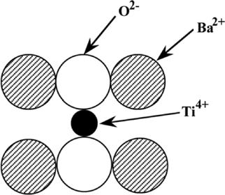
30 12.25 For each of the following crystal structures, represent the indicated plane in the manner of Figures.11 and.12, showing both anions and cations: (a) (100) plane for the rock salt crystal structure, (b) (110) plane for the cesium chloride crystal structure, (c) (111) plane for the zinc blende crystal structure, and (d) (110) plane for the perovskite crystal structure. (a) A (100) plane for the rock salt crystal structure would appear as (b) A (110) plane for the cesium chloride crystal structure would appear as (c) A (111) plane for the zinc blende crystal structure would appear as (d) A (110) plane for the perovskite crystal structure would appear as
31
32 Silicate Ceramics In terms of bonding, explain why silicate materials have relatively low densities. The silicate materials have relatively low densities because the atomic bonds are primarily covalent in nature (Table 12.1), and, therefore, directional. This limits the packing efficiency of the atoms, and therefore, the magnitude of the density.
33 12.27 Determine the angle between covalent bonds in an 4 SiO 4 tetrahedron. This problem asks for us to determine the angle between covalent bonds in the 4 SiO 4 tetrahedron. Below is shown one such tetrahedron situated within a cube. Now if we extend the base diagonal from one corner to the other, it is the case that (2 y) a + a 2a or y a 2 2 Furthermore, x a/2, and /2 1 tan θ x a y a 2/2 2 From which θ tan Now, solving for the angle φ φ Finally, the bond angle is just 2φ, or 2φ (2)(54.74 )
34 Imperfections in Ceramics Would you expect Frenkel defects for anions to exist in ionic ceramics in relatively large concentrations? Why or why not? Frenkel defects for anions would not exist in appreciable concentrations because the anion is quite large and is highly unlikely to exist as an interstitial.
35 12.29 Calculate the fraction of lattice sites that are Schottky defects for sodium chloride at its melting temperature (801 C). Assume an energy for defect formation of 2. ev. We are asked in this problem to calculate the fraction of lattice sites that are Schottky defects for NaCl at its melting temperature (801 C), assuming that the energy for defect formation is 2. ev. In order to solve this problem it is necessary to use Equation 12. and solve for the N s /N ratio. Rearrangement of this expression and substituting values for the several parameters leads to Ns N exp Qs 2kT exp 2. ev 5 (2)( ev/k)( K)
36 12.0 Calculate the number of Frenkel defects per cubic meter in zinc oxide at 1000 C. The energy for defect formation is 2.51 ev, while the density for ZnO is 5.55 g/cm at (1000 C). This problem asks that we compute the number of Frenkel defects per cubic meter in zinc oxide at 1000 C. of this problem is possible using Equation However, we must first determine the value of N, the number of lattice sites per cubic meter, which is possible using a modified form of Equation 4.2; thus N NA ρ A + A Zn O ( atoms/mol)(5.55 g/cm )(10 6 cm /m ) g/mol g/mol lattice sites/m And, finally the value of N fr is computed using Equation 12.2 as N fr N exp Q fr 2kT 28 ( lattice sites/m ) exp 2.51 ev 5 (2)( ev/k)( K) defects/m
37 12.1 Using the data given below that relate to the formation of Schottky defects in some oxide ceramic (having the chemical formula MO), determine the following: (a) The energy for defect formation (in ev), (b) The equilibrium number of Schottky defects per cubic meter at 1000 C, and (c) The identity of the oxide (i.e., what is the metal M?) T ( C) ρ (g/cm ) N s (m ) ? This problem provides for some oxide ceramic, at temperatures of 750 C and 1250 C, values for density and the number of Schottky defects per cubic meter. The (a) portion of the problem asks that we compute the energy for defect formation. To begin, let us combine a modified form of Equation 4.2 and Equation 12. as N s N exp Q s 2kT N ρ Q exp s A + A 2kT A M O Inasmuch as this is a hypothetical oxide material, we don't know the atomic weight of metal M, nor the value of Q s in the above equation. Therefore, let us write equations of the above form for two temperatures, T 1 and T 2. These are as follows: N N ρ Q exp + A 1 s s1 A M A O 2kT1 (12.S1a) N s2 N ρ Qs exp A + A 2kT A 2 M O 2 (12.S1b) Dividing the first of these equations by the second leads to N N NAρ 1 Qs exp A + A 2kT s1 M O 1 s2 NAρ 2 Qs exp A + A 2kT M O 2
38 which, after some algebraic manipulation, reduces to the form Ns 1 ρ 1 Qs 1 1 exp Ns2 ρ2 2k T1 T 2 (12.S2) Now, taking natural logarithms of both sides of this equation gives ln N s1 ρ 1 Qs 1 1 ln N ρ 2k T T s and solving for Q s leads to the expression Q s N s1 ρ 1 2k ln ln N s2 ρ T T 1 2 Let us take T C and T C, and we may compute the value of Q s as Q s m 5.50 g/cm (2)( ev/k) ln ln m 5.7 g/cm K K.40 ev (b) It is now possible to solve for N s at 1000 C using Equation 12.S2 above. This time let's take T C and T C. Thus, solving for N s1, substituting values provided in the problem statement and Q s determined above yields N s1 N ρ ρ exp Q 1 1 2k T T s2 1 s ( m )( 5.44 g/cm ).40 ev 1 1 exp g/cm (2)( ev/k) K K m
39 (c) And, finally, we want to determine the identity of metal M. This is possible by computing the atomic weight of M (A M ) from Equation 12.S1a. Rearrangement of this expression leads to N ρ Q N exp A + A kt A 1 s s1 M O 2 1 And, after further algebraic manipulation N ρ A 1 A M + Qs Ns1 exp 2kT 1 A O And, solving this expression for A M gives A N ρ A 1 M Qs Ns1 exp 2kT 1 A O Now, assuming that T C, the value of A M is A M 2 6 ( ions/mol)( 5.50 g/cm )(10 cm / m ) g/mol ev ( ions/m ) exp 5 (2)( ev/k)( K) 16.7 g/mol Upon consultation of the periodic table in Figure 2.6, the divalent metal (i.e., that forms M 2+ ions) that has an atomic weight closest to 16.7 g/mol is barium. Thus, this metal oxide is BaO.
40 12.2 In your own words, briefly define the term stoichiometric. Stoichiometric means having exactly the ratio of anions to cations as specified by the chemical formula for the compound.
41 12. If cupric oxide (CuO) is exposed to reducing atmospheres at elevated temperatures, some of the Cu 2+ ions will become Cu +. (a) Under these conditions, name one crystalline defect that you would expect to form in order to maintain charge neutrality. (b) How many Cu + ions are required for the creation of each defect? (c) How would you express the chemical formula for this nonstoichiometric material? (a) For a Cu 2+ O 2 compound in which a small fraction of the copper ions exist as Cu +, for each Cu + formed there is one less positive charge introduced (or one more negative charge). In order to maintain charge neutrality, we must either add an additional positive charge or subtract a negative charge. This may be accomplished be either creating Cu 2+ interstitials or O 2 vacancies. (b) There will be two Cu + ions required for each of these defects. (c) The chemical formula for this nonstoichiometric material is Cu 1+x O or CuO 1 x, where x is some small fraction.
42 12.4 (a) Suppose that Li 2 O is added as an impurity to CaO. If the Li + substitutes for Ca 2+, what kind of vacancies would you expect to form? How many of these vacancies are created for every Li + added? (b) Suppose that CaCl 2 is added as an impurity to CaO. If the Cl substitutes for O 2, what kind of vacancies would you expect to form? How many of the vacancies are created for every Cl added? (a) For Li + substituting for Ca 2+ in CaO, oxygen vacancies would be created. For each Li + substituting for Ca 2+, one positive charge is removed; in order to maintain charge neutrality, a single negative charge may be removed. Negative charges are eliminated by creating oxygen vacancies, and for every two Li + ions added, a single oxygen vacancy is formed. (b) For Cl substituting for O 2 in CaO, calcium vacancies would be created. For each Cl substituting for an O 2, one negative charge is removed; in order to maintain charge neutrality, two Cl ions will lead to the formation of one calcium vacancy.
43 12.5 What point defects are possible for Al 2 O as an impurity in MgO? How many Al + ions must be added to form each of these defects? For every Al + ion that substitutes for Mg 2+ in MgO, a single positive charge is added. Thus, in order to maintain charge neutrality, either a positive charge must be removed or a negative charge must be added. Negative charges are added by forming O 2 interstitials, which are not likely to form. Positive charges may be removed by forming Mg 2+ vacancies, and one magnesium vacancy would be formed for every two Al + ions added.
44 Ceramic Phase Diagrams 12.6 For the ZrO 2 CaO system (Figure 12.26), write all eutectic and eutectoid reactions for cooling. There is only one eutectic for the portion of the ZrO 2 CaO system shown in Figure It occurs at approximately 2250 C and 2.5 wt% CaO, and, upon cooling, the reaction is Liquid cubic ZrO + CaZrO 2 There are two eutectoids. One occurs at about 1000 C and about 2 wt% CaO; its reaction upon cooling is as follows: tetragonal monoclinic ZrO + cubic ZrO 2 2 The second eutectoid occurs at about 850 C and 7 wt% CaO. This reaction is cubic monoclinic ZrO + CaZr O 2 4 9
45 12.7 From Figure 12.25, the phase diagram for the MgO Al 2 O system, it may be noted that the spinel solid solution exists over a range of compositions, which means that it is nonstoichiometric at compositions other than 50 mol% MgO 50 mol% Al 2 O. (a) The maximum nonstoichiometry on the Al 2 O -rich side of the spinel phase field exists at about 1198 C (2271 K) corresponding to approximately 82 mol% (92 wt%) Al 2 O. Determine the type of vacancy defect that is produced and the percentage of vacancies that exist at this composition. (b) The maximum nonstoichiometry on the MgO-rich side of the spinel phase field exists at about 1198 C (2271 K) corresponding to approximately 9 mol% (62 wt%) Al 2 O. Determine the type of vacancy defect that is produced and the percentage of vacancies that exist at this composition. (a) For this portion of the problem we are to determine the type of vacancy defect that is produced on the Al 2 O -rich side of the spinel phase field (Figure 12.25) and the percentage of these vacancies at the maximum nonstoichiometry (82 mol% Al 2 O ). On the alumina-rich side of this phase field, there is an excess of Al + ions, which means that some of the Al + ions substitute for Mg 2+ ions. In order to maintain charge neutrality, Mg 2+ vacancies are formed, and for every Mg 2+ vacancy formed, two Al + ions substitute for three Mg 2+ ions. Now, we will calculate the percentage of Mg 2+ vacancies that exist at 82 mol% Al 2 O. Let us arbitrarily choose as our basis 50 MgO Al 2 O units of the stoichiometric material, which consists of 50 Mg 2+ ions and 100 Al + ions. Furthermore, let us designate the number of Mg 2+ vacancies as x, which means that 2x Al + ions have been added and x Mg 2+ ions have been removed (two of which are filled with Al + ions). Using our 50 MgO Al 2 O unit basis, the number of moles of Al 2 O in the nonstoichiometric material is ( x)/2; similarly the number of moles of MgO is (50 x). Thus, the expression for the mol% of Al 2 O is just x mol% Al 2 2O x + + (50 x) 2 If we solve for x when the mol% of Al 2 O 82, then x Thus, adding 2x or (2)(12.1) 24.2 Al + ions to the original material consisting of 100 Al + and 50 Mg 2+ ions will produce 12.1 Mg 2+ vacancies. Therefore, the percentage of vacancies is just % vacancies %
46 (b) Now, we are asked to make the same determinations for the MgO-rich side of the spinel phase field, for 9 mol% Al 2 O. In this case, Mg 2+ ions are substituting for Al + ions. Since the Mg 2+ ion has a lower charge than the Al + ion, in order to maintain charge neutrality, negative charges must be eliminated, which may be accomplished by introducing O 2 vacancies. For every 2 Mg 2+ ions that substitute for 2 Al + ions, one O 2 vacancy is formed. Now, we will calculate the percentage of O 2 vacancies that exist at 9 mol% Al 2 O. Let us arbitrarily choose as our basis 50 MgO Al 2 O units of the stoichiometric material which consists of 50 Mg 2+ ions 100 Al + ions. Furthermore, let us designate the number of O 2 vacancies as y, which means that 2y Mg 2+ ions have been added and 2y Al + ions have been removed. Using our 50 MgO Al 2 O unit basis, the number of moles of Al 2 O in the nonstoichiometric material is (100 2y)/2; similarly the number of moles of MgO is (50 + 2y). Thus, the expression for the mol% of Al 2 O is just 100 2y mol% Al 2 2O y + ( y) 2 If we solve for y when the mol% of Al 2 O 9, then y Thus, 7.91 O 2 vacancies are produced in the original material that had 200 O 2 ions. Therefore, the percentage of vacancies is just % vacancies %
47 12.8 When kaolinite clay [Al 2 (Si 2 O 5 )(OH) 4 ] is heated to a sufficiently high temperature, chemical water is driven off. (a) Under these circumstances, what is the composition of the remaining product (in weight percent Al 2 O )? (b) What are the liquidus and solidus temperatures of this material (a) The chemical formula for kaolinite clay may also be written as Al 2 O 2SiO 2-2H 2 O. Thus, if we remove the chemical water, the formula becomes Al 2 O 2SiO 2. The formula weight for Al 2 O is just (2)(26.98 g/mol) + ()(16.00 g/mol) g/mol; and for SiO 2 the formula weight is g/mol + (2)(16.00 g/mol) g/mol. Thus, the composition of this product, in terms of the concentration of Al 2 O, C Al2 O, in weight percent is just g/mol C Al2O wt% g/mol + (2)(60.09 g/mol) (b) The liquidus and solidus temperatures for this material as determined from the SiO 2 Al 2 O phase diagram, Figure 12.27, are 1825 C and 1587 C, respectively.
48 Brittle Fracture of Ceramics 12.9 Briefly explain (a) why there may be significant scatter in the fracture strength for some given ceramic material, and (b) why fracture strength increases with decreasing specimen size. (a) There may be significant scatter in the fracture strength for some given ceramic material because the fracture strength depends on the probability of the existence of a flaw that is capable of initiating a crack; this probability varies from specimen to specimen of the same material. (b) The fracture strength increases with decreasing specimen size because as specimen size decreases, the probably of the existence of a flaw of that is capable of initiating a crack diminishes.
49 12.40 The tensile strength of brittle materials may be determined using a variation of Equation 8.1. Compute the critical crack tip radius for an Al 2 O specimen that experiences tensile fracture at an applied stress of 275 MPa. Assume a critical surface crack length of 2 10 mm and a theoretical fracture strength of E/10, where E is the modulus of elasticity. We are asked for the critical crack tip radius for an Al 2 O material. From Equation 8.1 a σm 2σ0 ρ t 1/2 Fracture will occur when σ m reaches the fracture strength of the material, which is given as E/10; thus E a 2σ 0 10 ρ t 1/2 Or, solving for ρ t ρ t 400 aσ E From Table 12.5, E 9 GPa, and thus, ρ t ( ) (400) 2 10 mm (275 MPa) 2 2 ( 9 10 MPa) mm 0.9 nm
50 12.41 The fracture strength of glass may be increased by etching away a thin surface layer. It is believed that the etching may alter surface crack geometry (i.e., reduce crack length and increase the tip radius). Compute the ratio of the original and etched crack tip radii for an eightfold increase in fracture strength if two-thirds of the crack length is removed. This problem asks that we compute the crack tip radius ratio before and after etching. Let ρ t original crack tip radius, and ρ t etched crack tip radius Also, σ f σ f a a σ 8σ 0 0 Solving for ρt ρ t from the following 1/2 1/2 a a σ f 2σ σ 2σ ρ 0 f 0 ρt t yields 2 2 ρt σ a 8 σ a/ ρ σ a σ a t
51 Stress-Strain Behavior A three-point bending test is performed on a glass specimen having a rectangular cross section of height d 6 mm and width b 12 mm the distance between support points is 45 mm. (a) Compute the flexural strength if the load at fracture is 290 N. (b) The point of maximum deflection y occurs at the center of the specimen and is described by FL y 48EI where E is the modulus of elasticity and I is the cross-sectional moment of inertia. Compute y at a load of 266 N. (a) For this portion of the problem we are asked to compute the flexural strength for a glass specimen that is subjected to a three-point bending test. The flexural strength (Equation 12.7a) is just Ff L σ fs 2 2bd for a rectangular cross-section. Using the values given in the problem statement, σ fs ( ) ( ) ()(290 N) m 2 (2) m ( 6 10 m) N/m 45.MPa (b) We are now asked to compute the maximum deflection. From Table 12.5, the elastic modulus (E) for glass is 69 GPa. Also, the moment of inertia for a rectangular cross section (Figure 12.2) is just bd I 12 Thus, FL y bd 48E 12 4 FL Ebd ( ) ( )( )( ) (266 N) m (4) N/m m 6 10 m m mm
52 12.4 A circular specimen of MgO is loaded using a three-point bending mode. Compute the minimum possible radius of the specimen without fracture, given that the applied load is 425 N, the flexural strength is 105 MPa, and the separation between load points is 60 mm. We are asked to calculate the maximum radius of a circular specimen of MgO that is loaded using three-point bending. Solving for R from Equation 12.7b FL f R σ fsπ which, when substituting the parameters stipulated in the problem statement, yields 1/ R ( ) 6 2 ( N/m )( π) (425 N) m 1/ m 4.26 mm
53 12.44 A three-point bending test was performed on an aluminum oxide specimen having a circular cross section of radius.8 mm; the specimen fractured at a load of 950 N when the distance between the support points was 60 mm. Another test is to be performed on a specimen of this same material, but one that has a square cross section of 12 mm length on each edge. At what load would you expect this specimen to fracture if the support point separation is 40 mm? For this problem, the load is given at which a circular specimen of aluminum oxide fractures when subjected to a three-point bending test; we are then are asked to determine the load at which a specimen of the same material having a square cross-section fractures. It is first necessary to compute the flexural strength of the aluminum oxide, Equation 12.7b, and then, using this value, we may calculate the value of F f in Equation 12.7a. From Equation 12.7b σ fs Ff L π R ( ) (950 N) m N/m 1MPa ( π) (.8 10 m) Now, solving for F f from Equation 12.7a, realizing that b d 12 mm, yields F f 2σ d fs L 6 2 (2)( 1 10 N / m )( m) 95N ( ) () m
54 12.45 (a) A three-point transverse bending test is conducted on a cylindrical specimen of aluminum oxide having a reported flexural strength of 90 MPa. If the specimen radius is 2.8 mm and the support point separation distance is 40 mm, predict whether or not you would expect the specimen to fracture when a load of 620 N is applied. Justify your prediction. (b) Would you be 100% certain of the prediction in part (a)? Why or why not? (a) This portion of the problem asks that we determine whether or not a cylindrical specimen of aluminum oxide having a flexural strength of 90 MPa and a radius of 2.8 mm will fracture when subjected to a load of 620 N in a three-point bending test; the support point separation is given as 40 mm. Using Equation 12.7b we will calculate the value of σ; if this value is greater than σ fs (90 MPa), then fracture is expected to occur. Employment of Equation 12.7b yields FL σ π R ( ) (620 N) m N/m 60 MPa ( π) ( m) Since this value is less than the given value of σ fs (90 MPa), then fracture is not predicted. (b) The certainty of this prediction is not 100% because there is always some variability in the flexural strength for ceramic materials, and since this value of σ (60 MPa) is relatively close to σ fs (90 MPa) then there is some chance that fracture will occur.
55 Mechanisms of Plastic Deformation Cite one reason why ceramic materials are, in general, harder yet more brittle than metals. Crystalline ceramics are harder yet more brittle than metals because they (ceramics) have fewer slip systems, and, therefore, dislocation motion is highly restricted.
56 Miscellaneous Mechanical Considerations The modulus of elasticity for beryllium oxide (BeO) having 5 vol% porosity is 10 GPa (a) Compute the modulus of elasticity for the nonporous material. (b) Compute the modulus of elasticity for 10 vol% porosity. (a) This portion of the problem requests that we compute the modulus of elasticity for nonporous BeO given that E 10 GPa for a material having 5 vol% porosity. Thus, we solve Equation 12.9 for E 0, using P 0.05, which gives E E P + 0.9P 10 GPa 42GPa 2 1 (1.9)(0.05) + (0.9)(0.05) (b) Now we are asked to determine the value of E at P 10 vol% (i.e., 0.10). Using Equation 12.9 we get ( ) E E P+ P + 2 (42 GPa) 1 (1.9)(0.10) (0.9)(0.10) 280 GPa
57 12.48 The modulus of elasticity for boron carbide (B 4 C) having 5 vol% porosity is 290 GPa. (a) Compute the modulus of elasticity for the nonporous material. (b) At what volume percent porosity will the modulus of elasticity be 25 GPa? (a) This portion of the problem requests that we compute the modulus of elasticity for nonporous B 4 C given that E 290 GPa for a material having 5 vol% porosity. Thus, we solve Equation 12.9 for E 0, using P 0.05, which gives E E P + 0.9P 290 GPa 20GPa 2 1 (1.9)(0.05) + (0.9)(0.05) (b) Now we are asked to compute the volume percent porosity at which the elastic modulus of B 4 C is 25 MPa ( psi). Since from part (a), E 0 20 GPa, and using Equation 12.9 we get E E 0 25 MPa 20 MPa P + 0.9P2 Or P 1.9 P Now, solving for the value of P using the quadratic equation solution yields P 1.9 ± ( 1.9)2 (4)(0.9)(0.266) (2)(0.9) The positive and negative roots are P P Obviously, only the negative root is physically meaningful, and therefore the value of the porosity to give the desired modulus of elasticity is 15.1 vol%.
58 12.49 Using the data in Table 12.5, do the following: (a) Determine the flexural strength for nonporous MgO assuming a value of.75 for n in Equation (b) Compute the volume fraction porosity at which the flexural strength for MgO is 62 MPa. (a) This part of the problem asks us to determine the flexural strength of nonporous MgO assuming that the value of n in Equation is.75. Taking natural logarithms of both sides of Equation yields ln σ fs lnσ np 0 In Table 12.5 it is noted that for P 0.05, σ fs 105 MPa. For the nonporous material P 0 and, ln σ 0 ln σ fs. Solving for ln σ 0 from the above equation and using these data gives lnσ ln σ fs + np 0 ln (105 MPa) + (.75)(0.05) or σ 0 e MPa (b) Now we are asked to compute the volume percent porosity to yield a σ fs of 62 MPa. Taking the natural logarithm of Equation and solving for P leads to P σ ln 0 ln fs n σ ln (127 MPa) ln (62 MPa) or 19 vol%
59 12.50 The flexural strength and associated volume fraction porosity for two specimens of the same ceramic material are as follows: σ fs (MPa) P (a) Compute the flexural strength for a completely nonporous specimen of this material. (b) Compute the flexural strength for a 0.10 volume fraction porosity. (a) Given the flexural strengths at two different volume fraction porosities, we are asked to determine the flexural strength for a nonporous material. If the natural logarithm is taken of both sides of Equation 12.10, then lnσ ln σ fs 0 np Using the data provided in the problem statement, two simultaneous equations may be written as ln (100 MPa) ln σ 0 (0.05) n ln (50 MPa) ln σ 0 (0.20) n Solving for n and σ 0 leads to n 4.62 and σ MPa. For the nonporous material, P 0, and, from Equation 12.10, σ 0 σ fs. Thus, σ fs for P 0 is 126 MPa. (b) Now, we are asked for σ fs at P 0.10 for this same material. Utilizing Equation yields σ fs σ exp ( ) 0 np (126 MPa) exp [ (4.62)(0.10)] 79.4 MPa
N = N A Pb A Pb. = ln N Q v kt. = kt ln v N
 5. Calculate the energy for vacancy formation in silver, given that the equilibrium number of vacancies at 800 C (1073 K) is 3.6 10 3 m 3. The atomic weight and density (at 800 C) for silver are, respectively,
CHAPTER 12 STRUCTURES AND PROPERTIES OF CERAMICS PROBLEM SOLUTIONS
 CHAPTER 12 STRUCTURES AND PROPERTIES OF CERAMICS PROBLEM SOLUTIONS Crystal Structures 12.1 For a ceramic compound, what are the two characteristics of the component ions that determine the crystal structure?
CHAPTER 3 THE STRUCTURE OF CRYSTALLINE SOLIDS PROBLEM SOLUTIONS
 CHAPTER THE STRUCTURE OF CRYSTALLINE SOLIDS PROBLEM SOLUTIONS Fundamental Concepts.1 What is the difference between atomic structure and crystal structure? Atomic structure relates to the number of protons
Chapter 3. The structure of crystalline solids 3.1. Crystal structures
 Chapter 3. The structure of crystalline solids 3.1. Crystal structures 3.1.1. Fundamental concepts 3.1.2. Unit cells 3.1.3. Metallic crystal structures 3.1.4. Ceramic crystal structures 3.1.5. Silicate
Remember the purpose of this reading assignment is to prepare you for class. Reading for familiarity not mastery is expected.
 Remember the purpose of this reading assignment is to prepare you for class. Reading for familiarity not mastery is expected. After completing this reading assignment and reviewing the intro video you
Atomic Arrangement. Primer Materials For Science Teaching Spring
 Atomic Arrangement Primer Materials For Science Teaching Spring 2016 31.3.2015 Levels of atomic arrangements No order In gases, for example the atoms have no order, they are randomly distributed filling
Atomic Arrangement. Primer in Materials Spring
 Atomic Arrangement Primer in Materials Spring 2017 30.4.2017 1 Levels of atomic arrangements No order In gases, for example the atoms have no order, they are randomly distributed filling the volume to
1. Demonstrate that the minimum cation-to-anion radius ratio for a coordination number of 8 is
 1. Demonstrate that the minimum cation-to-anion radius ratio for a coordination number of 8 is 0.732. This problem asks us to show that the minimum cation-to-anion radius ratio for a coordination number
Chapter 12: Structures & Properties of Ceramics
 Chapter 12: Structures & Properties of Ceramics ISSUES TO ADDRESS... Structures of ceramic materials: How do they differ from those of metals? Point defects: How are they different from those in metals?
Introduction to Engineering Materials ENGR2000 Chapter 12: Structures and Properties of Ceramics. Dr. Coates
 Introduction to Engineering Materials ENGR2000 Chapter 12: Structures and Properties of Ceramics Dr. Coates 12.1 Introduction Ceramics Compounds between metallic & non-metallic elements Predominantly ionic
Chapter 12: Structures & Properties of Ceramics
 Chapter 12: Structures & Properties of Ceramics ISSUES TO ADDRESS... Bonding and structure of ceramic materials as compared with metals Chapter 12-1 Atomic Bonding in Ceramics Bonding: -- Can be ionic
Experiment 7: Understanding Crystal Structures
 Experiment 7: Understanding Crystal Structures To do well in this laboratory experiment you need to be familiar with the concepts of lattice, crystal structure, unit cell, coordination number, the different
4. Interpenetrating simple cubic
 2 1. The correct structure t of CsClCl crystal is 1. Simple cubic 2. Body centered cubic 3. Face centered cubic 4. Interpenetrating simple cubic If corner as well as the particle at the center are same
PY2N20 Material Properties and Phase Diagrams
 PY2N20 Material Properties and Phase Diagrams Lecture 10 P. Stamenov, PhD School of Physics, TCD PY2N20-10 Modern CMOS pair structure Photolithographic Process CMOS Processing Steps Cu Damascene Process
Metallic and Ionic Structures and Bonding
 Metallic and Ionic Structures and Bonding Ionic compounds are formed between elements having an electronegativity difference of about 2.0 or greater. Simple ionic compounds are characterized by high melting
Experiment 2a Models of the Solid State*
 Experiment 2a Models of the Solid State* *This lab is adapted from solid-state labs offered at Purdue and Rice Universities. Introduction The structures of metals and simple ionic solids are prototypes
Chapter Outline: Ceramics. Chapter 13: Structure and Properties of Ceramics
 Chapter Outline: Ceramics Chapter 13: Structure and Properties of Ceramics Crystal Structures Silicate Ceramics Carbon Imperfections in Ceramics Optional reading: 13.6 13.10 University of Virginia, Dept.
Lecture 04 Structure of Ceramics 1 Ref: Barsoum, Fundamentals of Ceramics, Ch03, McGraw-Hill, 2000.
 MME 467 Ceramics for Advanced Applications Lecture 04 Structure of Ceramics 1 Ref: Barsoum, Fundamentals of Ceramics, Ch03, McGraw-Hill, 2000. Prof. A. K. M. Bazlur Rashid Department of MME, BUET, Dhaka
S.No. Crystalline Solids Amorphous solids 1 Regular internal arrangement of irregular internal arrangement of particles
 Classification of solids: Crystalline and Amorphous solids: S.No. Crystalline Solids Amorphous solids 1 Regular internal arrangement of irregular internal arrangement of particles particles 2 Sharp melting
VERY SHORT ANSWER TYPE QUESTIONS (1 Mark)
") UNIT I 10 Chemistry-XII THE SOLID STATE VERY SHORT ANSWER TYPE QUESTIONS (1 Mark) Q. 1. What do you mean by paramagnetic substance? Ans. Weakly attracted by magnetic eld and these substances are made of
UNIT I 10 Chemistry-XII THE SOLID STATE VERY SHORT ANSWER TYPE QUESTIONS (1 Mark) Q. 1. What do you mean by paramagnetic substance? Ans. Weakly attracted by magnetic eld and these substances are made of
High Temperature Materials. By Docent. N. Menad. Luleå University of Technology ( Sweden )
") Course KGP003 Ch. 12 High Temperature Materials By Docent. N. Menad Dept. of Chemical Engineering and Geosciences Div. Of process metallurgy Luleå University of Technology ( Sweden ) Ceramic materials
Course KGP003 Ch. 12 High Temperature Materials By Docent. N. Menad Dept. of Chemical Engineering and Geosciences Div. Of process metallurgy Luleå University of Technology ( Sweden ) Ceramic materials
Metal Structure. Chromium, Iron, Molybdenum, Tungsten Face-centered cubic (FCC)
") Metal Structure Atoms held together by metallic bonding Crystalline structures in the solid state, almost without exception BCC, FCC, or HCP unit cells Bodycentered cubic (BCC) Chromium, Iron, Molybdenum,
Metal Structure Atoms held together by metallic bonding Crystalline structures in the solid state, almost without exception BCC, FCC, or HCP unit cells Bodycentered cubic (BCC) Chromium, Iron, Molybdenum,
Solids. properties & structure
 Solids properties & structure Determining Crystal Structure crystalline solids have a very regular geometric arrangement of their particles the arrangement of the particles and distances between them is
Report Form for Experiment 6: Solid State Structures
 Report Form for Experiment 6: Solid State Structures Note: Many of these questions will not make sense if you are not reading the accompanying lab handout. Station 1. Simple Cubic Lattice 1. How many unit
Chapter 12: Structures of Ceramics
 Chapter 12: Structures of Ceramics Outline Introduction Crystal structures Ceramic structure AX-type crystal structures A m X p -type A m B n X p - type Silicate ceramics Carbon Chapter 12 - Ceramics Two
Metallic & Ionic Solids. Crystal Lattices. Properties of Solids. Network Solids. Types of Solids. Chapter 13 Solids. Chapter 13
 1 Metallic & Ionic Solids Chapter 13 The Chemistry of Solids Jeffrey Mack California State University, Sacramento Crystal Lattices Properties of Solids Regular 3-D arrangements of equivalent LATTICE POINTS
Advanced Ceramics for Strategic Applications Prof. H. S. Maiti Department of Mechanical Engineering Indian Institute of Technology, Kharagpur
 Advanced Ceramics for Strategic Applications Prof. H. S. Maiti Department of Mechanical Engineering Indian Institute of Technology, Kharagpur Lecture -3 Crystal Structure Having made some introductory
SOLID STATE CHEMISTRY
 SOLID STATE CHEMISTRY Crystal Structure Solids are divided into 2 categories: I. Crystalline possesses rigid and long-range order; its atoms, molecules or ions occupy specific positions, e.g. ice II. Amorphous
Chapter 12: Structures & Properties of Ceramics
 Chapter 12: Structures & Properties of Ceramics ISSUES TO ADDRESS... How do the crystal structures of ceramic materials differ from those for metals? How do point defects in ceramics differ from those
Inorganic Chemistry I (CH331) Solid-state Chemistry I (Crystal structure) Nattapol Laorodphan (Chulabhorn Building, 4 th Floor)
 Solid-state Chemistry I (Crystal structure) Nattapol Laorodphan (Chulabhorn Building, 4 th Floor)") Inorganic Chemistry I (CH331) Solid-state Chemistry I (Crystal structure) Nattapol Laorodphan (Chulabhorn Building, 4 th Floor) 7/2013 N.Laorodphan 1 Text books : 1. D.F. Sheiver, P.W. Atkins & C.H. Langford
Inorganic Chemistry I (CH331) Solid-state Chemistry I (Crystal structure) Nattapol Laorodphan (Chulabhorn Building, 4 th Floor) 7/2013 N.Laorodphan 1 Text books : 1. D.F. Sheiver, P.W. Atkins & C.H. Langford
Crystal Models. Figure 1.1 Section of a three-dimensional lattice.
 Crystal Models The Solid-State Structure of Metals and Ionic Compounds Objectives Understand the concept of the unit cell in crystalline solids. Construct models of unit cells for several metallic and
Lecture 05 Structure of Ceramics 2 Ref: Barsoum, Fundamentals of Ceramics, Ch03, McGraw-Hill, 2000.
 MME 467 Ceramics for Advanced Applications Lecture 05 Structure of Ceramics 2 Ref: Barsoum, Fundamentals of Ceramics, Ch03, McGraw-Hill, 2000. Prof. A. K. M. Bazlur Rashid Department of MME, BUET, Dhaka
CHAPTER 6 MECHANICAL PROPERTIES OF METALS PROBLEM SOLUTIONS
 CHAPTER 6 MECHANICAL PROPERTIES OF METALS PROBLEM SOLUTIONS Concepts of Stress and Strain 6.1 Using mechanics of materials principles (i.e., equations of mechanical equilibrium applied to a free-body diagram),
ME 254 MATERIALS ENGINEERING 1 st Semester 1430/ st Med-Term Exam (1.5 hrs)
") ME 254 MATERIALS ENGINEERING 1 st Semester 1430/1431 1 st Med-Term Exam (1.5 hrs) قسم الهندسة الميكانيكية Question 1 a) Classify the materials based on their properties and performance, give some examples.
ME 254 MATERIALS ENGINEERING 1 st Semester 1430/1431 1 st Med-Term Exam (1.5 hrs) قسم الهندسة الميكانيكية Question 1 a) Classify the materials based on their properties and performance, give some examples.
Practice Problems Set II
 P1. For the HCP crystal structure, (a) show that the ideal c/a ratio is 1.633; (b) show that the atomic packing factor for HCP is 0.74. (a) A sketch of one-third of an HCP unit cell is shown below. Consider
CHAPTER 7 MECHANICAL PROPERTIES PROBLEM SOLUTIONS
 Excerpts from this work may be reproduced by instructors for distribution on a not-for-profit basis for testing or instructional purposes only to students enrolled in courses for which the textbook has
HW# 5 CHEM 281 Louisiana Tech University, POGIL(Process Oriented Guided Inquiry Learning) Exercise on Chapter 3. Structures of Ionic Solids. Why?
 Exercise on Chapter 3. Structures of Ionic Solids. Why?") HW# 5 CHEM 281 Louisiana Tech University, POGIL(Process Oriented Guided Inquiry Learning) Exercise on Chapter 3. Structures of Ionic Solids. Why? Many ionic structures may be described as close-packed
HW# 5 CHEM 281 Louisiana Tech University, POGIL(Process Oriented Guided Inquiry Learning) Exercise on Chapter 3. Structures of Ionic Solids. Why? Many ionic structures may be described as close-packed
Chem 241. Lecture 20. UMass Amherst Biochemistry... Teaching Initiative
 Chem 241 Lecture 20 UMass Amherst Biochemistry... Teaching Initiative Announcement March 26 Second Exam Recap Ellingham Diagram Inorganic Solids Unit Cell Fractional Coordinates Packing... 2 Inorganic
UNIT-1 SOLID STATE. Ans. Gallium (Ga) is a silvery white metal, liquid at room temp. It expands by 3.1% on solidifica-tion.
 is a silvery white metal, liquid at room temp. It expands by 3.1% on solidifica-tion.") UNIT-1 SOLID STATE 1 MARK QUESTIONS Q. 1. Name a liquefied metal which expands on solidification. Ans. Gallium (Ga) is a silvery white metal, liquid at room temp. It expands by 3.1% on solidifica-tion.
UNIT-1 SOLID STATE 1 MARK QUESTIONS Q. 1. Name a liquefied metal which expands on solidification. Ans. Gallium (Ga) is a silvery white metal, liquid at room temp. It expands by 3.1% on solidifica-tion.
For this activity, all of the file labels will begin with a Roman numeral IV.
 I V. S O L I D S Name Section For this activity, all of the file labels will begin with a Roman numeral IV. A. In Jmol, open the SCS file in IV.A.1. Click the Bounding Box and Axes function keys. Use the
CHEM1902/ N-2 November 2014
 CHEM1902/4 2014-N-2 November 2014 The cubic form of boron nitride (borazon) is the second-hardest material after diamond and it crystallizes with the structure shown below. The large spheres represent
Diamond. There are four types of solid: -Hard Structure - Tetrahedral atomic arrangement. What hybrid state do you think the carbon has?
 Bonding in Solids Bonding in Solids There are four types of solid: 1. Molecular (formed from molecules) - usually soft with low melting points and poor conductivity. 2. Covalent network - very hard with
There are four types of solid:
 Bonding in Solids There are four types of solid: 1. Molecular (formed from molecules) - usually soft with low melting points and poor conductivity. 2. Covalent network - very hard with very high melting
Ionic Bonding. Chem
 Whereas the term covalent implies sharing of electrons between atoms, the term ionic indicates that electrons are taken from one atom by another. The nature of ionic bonding is very different than that
Problem Set # 1 Solutions CHAPTERS 2 & 3 ATOMIC STRUCTURE AND INTERATOMIC BONDING and THE STRUCTURE OF CRYSTALLINE SOLIDS
 Problem Set # Solutions CHAPTERS & ATOMIC STRUCTURE AND INTERATOMIC BONDING and THE STRUCTURE OF CRYSTALLINE SOLIDS Assigned:.7(a),.9,.,.6,.8,.7(a),.7,.9,. (graded problems indicated in bold).7 (a) The
Physical Chemistry I. Crystal Structure
 Physical Chemistry I Crystal Structure Crystal Structure Introduction Crystal Lattice Bravis Lattices Crytal Planes, Miller indices Distances between planes Diffraction patters Bragg s law X-ray radiation
E12 UNDERSTANDING CRYSTAL STRUCTURES
 E1 UNDERSTANDING CRYSTAL STRUCTURES 1 Introduction In this experiment, the structures of many elements and compounds are rationalized using simple packing models. The pre-work revises and extends the material
Bonding and Packing: building crystalline solids
 Bonding and Packing: building crystalline solids The major forces of BONDING Gravitational forces: F = G m m 1 2 F = attractive forces between 2 bodies G = universal graviational constant (6.6767 * 10
CHAPTER 4. Crystal Structure
 CHAPTER 4 Crystal Structure We can assume minerals to be made of orderly packing of atoms or rather ions or molecules. Many mineral properties like symmetry, density etc are dependent on how the atoms
Full file at
 CHAPTER 2 ATOMIC STRUCTURE AND INTERATOMIC BONDING PROBLEM SOLUTIONS Fundamental Concepts Electrons in Atoms 2.1 Cite the difference between atomic mass and atomic weight. Atomic mass is the mass of an
Problems & Solutions -I. Prof.P. Ravindran, Department of Physics, Central University of Tamil Nadu, India
 Problems & Solutions -I 1 Prof.P. Ravindran, Department of Physics, Central University of Tamil Nadu, India http://folk.uio.no/ravi/cmp2013 Geometry of a Cube 2 Face Diagonal f 2 a 2 f a 2 a 2 Body Diagonal
Inorganic Exam 1 Chm October 2010
 Inorganic Exam 1 Chm 451 28 October 2010 Name: Instructions. Always show your work where required for full credit. 1. In the molecule CO 2, the first step in the construction of the MO diagram was to consider
Ionic bonds occur between a metal and a nonmetal. Covalent bonds occur between two or more nonmetals. Metallic bonds occur between metal atoms only.
 Ionic bonds occur between a metal and a nonmetal. Covalent bonds occur between two or more nonmetals. Metallic bonds occur between metal atoms only. Using chemical equations to show ionization: Na Na +
CHAPTER 4 IMPERFECTIONS IN SOLIDS PROBLEM SOLUTIONS
 4-1 CHAPTER 4 IMPERFECTIONS IN SOLIDS PROBLEM SOLUTIONS Vacancies and Self-Interstitials 4.1 In order to compute the fraction of atom sites that are vacant in copper at 1357 K, we must employ Equation
Materials for Civil and Construction Engineers CHAPTER 2. Nature of Materials
 Materials for Civil and Construction Engineers CHAPTER 2 Nature of Materials Bonds 1. Primary Bond: forms when atoms interchange or share electrons in order to fill the outer (valence) shells like noble
Topics to discuss...
 MME 467: Ceramics for Advanced Applications Lecture 18 Defects in Ceramics 2 Ref: Barsoum, Fundamentals of Ceramics, Ch6, McGraw-Hill, 2000 Prof. A. K. M. B. Rashid Department of MME, BUET, Dhaka Topics
Ceramics. Ceramic Materials. Ceramics / Introduction. Classifications of Ceramics
 Ceramic Materials Outline Structure and Properties of Ceramics Introduction Classifications of Ceramics Crystal Structures Silicate Ceramics Ceramic Phase Diagram Carbon based materials Why study ceramic
Ceramic Bonding. CaF 2 : large SiC: small
 Recall ceramic bonding: - Mixed ionic and covalent. - % ionic character ( f ) increases with difference in electronegativity Large vs small ionic bond character: Ceramic Bonding CaF : large SiC: small
Chapter 2. Atomic Structure
 Chapter 2 Atomic Structure 2 6 (a) Aluminum foil used for storing food weighs about 0. g per square cm. How many atoms of aluminum are contained in one 6.25 cm 2 size of foil? (b) Using the densities and
Bravais Lattice + Basis = Crystal Structure
 Bravais Lattice + Basis = Crystal Structure A crystal structure is obtained when identical copies of a basis are located at all of the points of a Bravais lattice. Consider the structure of Cr, a I-cubic
Ceramics Ceramics keramikos - burnt stuff in Greek - desirable properties of ceramics are normally achieved through a high temperature heat treatment
 Ceramics Ceramics keramikos - burnt stuff in Greek - desirable properties of ceramics are normally achieved through a high temperature heat treatment process (firing). Usually a compound between metallic
SOLID STATE MODULE - 3. Objectives. Solid State. States of matter. Notes
 Solid State MODULE - 3 8 SOLID STATE Y ou are aware that the matter exists in three different states viz., solid, liquid and gas. In these, the constituent particles (atoms, molecules or ions) are held
EXAM TWO PART ONE CHM 451 (INORGANIC CHEMISTRY) DR. MATTSON 1 NOVEMBER 2012
 DR. MATTSON 1 NOVEMBER 2012") EXAM TWO PART ONE CHM 451 (INORGANIC CHEMISTRY) DR. MATTSON 1 NOVEMBER 2012 NAME: Instructions: This exam has two parts. In Part One, only a pencil and a non-programmable calculator may be used. When you
EXAM TWO PART ONE CHM 451 (INORGANIC CHEMISTRY) DR. MATTSON 1 NOVEMBER 2012 NAME: Instructions: This exam has two parts. In Part One, only a pencil and a non-programmable calculator may be used. When you
1 8 =1 8 8 =1 6 =3. Unit cell Atoms at corner Atoms at faces Atoms at centre. Total no. of atoms per unit cell. bcc. fcc
 Q. No. Amorphous substances show () Short and long range order (2) Short range order (3) Long range order (4) Have no sharp M.P. Option and 3 are correct Option 2 2 and 3 are correct Option 3 3 and 4 are
3.3 Show for the body-centered cubic crystal structure that the unit cell edge length a and the atomic radius R are related through a =4R/ 3.
 EGR 1 Materials Science, HW, CH :, 6, 7, 11, 0,, 0a-c,. Show for the body-centered cubic crystal structure that the unit cell edge length a and the atomic radius R are related through a =4R/. Consider
Class XII Chapter 1 The Solid State Chemistry. Define the term amorphous give a few examples of amorphous solids.
 Book Name: NCERT Solution Question 1: Define the term amorphous give a few examples of amorphous solids. Solution 1: Amorphous solids are the solids whose constituent particles are of irregular shapes
CRYSTAL STRUCTURES WITH CUBIC UNIT CELLS
 CRYSTAL STRUCTURES WITH CUBIC UNIT CELLS Crystalline solids are a three dimensional collection of individual atoms, ions, or whole molecules organized in repeating patterns. These atoms, ions, or molecules
Class XII Chapter 1 The Solid State Chemistry
 Question 1.1: Define the term 'amorphous'. Give a few examples of amorphous solids. Amorphous solids are the solids whose constituent particles are of irregular shapes and have short range order. These
WORKING WITH ELECTRON MICROPROBE DATA FROM A HIGH PRESSURE EXPERIMENT CALCULATING MINERAL FORMULAS, UNIT CELL CONTENT, AND GEOTHERMOMETRY
 WORKING WITH ELECTRON MICROPROBE DATA FROM A HIGH PRESSURE EXPERIMENT CALCULATING MINERAL FORMULAS, UNIT CELL CONTENT, AND GEOTHERMOMETRY Brandon E. Schwab Department of Geology Humboldt State University
Chapter 2: INTERMOLECULAR BONDING (4rd session)
") Chapter 2: INTERMOLECULAR BONDING (4rd session) ISSUES TO ADDRESS... Secondary bonding The structure of crystalline solids 1 REVIEW OF PREVIOUS SESSION Bonding forces & energies Interatomic vs. intermolecular
Chapter 2: INTERMOLECULAR BONDING (4rd session) ISSUES TO ADDRESS... Secondary bonding The structure of crystalline solids 1 REVIEW OF PREVIOUS SESSION Bonding forces & energies Interatomic vs. intermolecular
Solid State. Subtopics
 01 Solid State Chapter 01: Solid State Subtopics 1.0 Introduction 1.1 Classification of solids 1.2 Classification of crystalline solids 1.3 Unit cell, two and three dimensional lattices and number of atoms
The exam time is 1hr45 minutes. Try to finish this practice exam in the same time.
 Practice exam for final exam, Chem 1210, Dr. Wu Note: The exam time is 1hr45 minutes. Try to finish this practice exam in the same time. 1. Which of the following gases will exhibit the least ideal behavior?
Chapter 12. Solids and Modern Materials
 Lecture Presentation Chapter 12 Solids and Modern Materials Graphene Thinnest, strongest known material; only one atom thick Conducts heat and electricity Transparent and completely impermeable to all
Unit wise Marks Distribution of 10+2 Syllabus
 Unit wise Marks Distribution of 10+2 Syllabus S.No Unit Name Marks 1 I Solid State 4 2 II Solutions 5 3 III Electro Chemistry 5 4 IV Chemical Kinetics 5 5 V Surface Chemistry 4 6 VI General Principles
Condensed Matter A Week 2: Crystal structure (II)
") QUEEN MARY, UNIVERSITY OF LONDON SCHOOL OF PHYSICS AND ASTRONOMY Condensed Matter A Week : Crystal structure (II) References for crystal structure: Dove chapters 3; Sidebottom chapter. Last week we learnt
QUEEN MARY, UNIVERSITY OF LONDON SCHOOL OF PHYSICS AND ASTRONOMY Condensed Matter A Week : Crystal structure (II) References for crystal structure: Dove chapters 3; Sidebottom chapter. Last week we learnt
The Solid State. Phase diagrams Crystals and symmetry Unit cells and packing Types of solid
 The Solid State Phase diagrams Crystals and symmetry Unit cells and packing Types of solid Learning objectives Apply phase diagrams to prediction of phase behaviour Describe distinguishing features of
CHEMISTRY The Molecular Nature of Matter and Change
 CHEMISTRY The Molecular Nature of Matter and Change Third Edition Chapter 12 Copyright The McGraw-Hill Companies, Inc. Permission required for reproduction or display. Chapter 11 INTERMOLECULAR FORCES
Module-2. Atomic Structures, Interatomic Bonding and Structure of Crystalline Solids
 Module-2 Atomic Structures, Interatomic Bonding and Structure of Crystalline Solids Contents 1) Atomic Structure and Atomic bonding in solids 2) Crystal structures, Crystalline and Noncrystalline materials
INTERMOLECULAR FORCES AND CONDENSED STATES
 INTERMOLECULAR FORCES AND CONDENSED STATES I. Intermolecular Forces A. Types of Intermolecular Forces. 1. Van der Waals forces = attractive forces that exist between neutral molecules. a. Are much weaker
What happens when substances freeze into solids? Less thermal energy available Less motion of the molecules More ordered spatial properties
 Chapter #16 Liquids and Solids 16.1) Intermolecular Forces 16.2) The Liquid State 16.3) An Introduction to Structures and Types of Solids 16.4) Structure and Bonding of Metals 16.5) Carbon and Silicon:
ก ก ก Intermolecular Forces: Liquids, Solids, and Phase Changes
 ก ก ก Intermolecular Forces: Liquids, Solids, and Phase Changes ก ก ก ก Mc-Graw Hill 1 Intermolecular Forces: Liquids, Solids, and Phase Changes 12.1 An Overview of Physical States and Phase Changes 12.2
2. Relative molecular mass, M r - The relative molecular mass of a molecule is the average mass of the one molecule when compared with
 Chapter 3: Chemical Formulae and Equations 1. Relative atomic mass, A r - The relative atomic mass of an element is the average mass of one atom of an element when compared with mass of an atom of carbon-12
554 Chapter 10 Liquids and Solids
 554 Chapter 10 Liquids and Solids above 7376 kpa, CO 2 is a supercritical fluid, with properties of both gas and liquid. Like a gas, it penetrates deep into the coffee beans; like a liquid, it effectively
Chapter 12 INTERMOLECULAR FORCES. Covalent Radius and van der Waals Radius. Intraand. Intermolecular Forces. ½ the distance of non-bonded
 Chapter 2 INTERMOLECULAR FORCES Intraand Intermolecular Forces Covalent Radius and van der Waals Radius ½ the distance of bonded ½ the distance of non-bonded Dipole Dipole Interactions Covalent and van
Lecture 4! ü Review on atom/ion size! ü Crystal structure (Chap 4 of Nesseʼs book)!
!") Lecture 4! ü Review on atom/ion size! ü Crystal structure (Chap 4 of Nesseʼs book)! 15 C 4+ 42 Si 4+ Size of atoms! Hefferan and O Brien, 2010; Earth Materials Force balance! Crystal structure (Chap. 4)!
Lecture 4! ü Review on atom/ion size! ü Crystal structure (Chap 4 of Nesseʼs book)! 15 C 4+ 42 Si 4+ Size of atoms! Hefferan and O Brien, 2010; Earth Materials Force balance! Crystal structure (Chap. 4)!
Chm October Molecular Orbitals. Instructions. Always show your work for full credit.
 Inorganic Exam 2 Chm 451 29 October 2009 Name: Instructions. Always show your work for full credit. Molecular Orbitals 1. (4 pts) An unusual structure, and one for which there are probably no real examples
MODERN PUBLISHERS (Producers of Quality Text & Competition Books)
") MODERN PUBLISHERS (Producers of Quality Text & Competition Books) UR ADDRESSES IN INDIA MBD PRINTOGRAPHICS (P) LTD. Ram Nagar, Industrial Area, Gagret, Distt. Una (H.P.) and...write to save nature we
MODERN PUBLISHERS (Producers of Quality Text & Competition Books) UR ADDRESSES IN INDIA MBD PRINTOGRAPHICS (P) LTD. Ram Nagar, Industrial Area, Gagret, Distt. Una (H.P.) and...write to save nature we
THE STRUCTURE OF CRYSTALLINE SOLIDS PROBLEM SOLUTIONS
 THE STRUCTURE OF CRYSTALLINE SOLIDS PROBLEM SOLUTIONS Fundamental Concepts. What is the difference between atomic structure and crystal structure? Atomic structure relates to the number of protons and
ionic solids Ionic Solids
 ionic solids Ionic Solids Properties characteristic of ionic solids low conductivity as solids, high when molten high melting points hard brittle solids soluble in polar solvents high melting Hardness
Definitions, Closest packing schemes Interstitial sites Other packing schemes Polymorphism (disintegrating buttons) Alloys. Closest packing of coins
 Alloys. Closest packing of coins") Definitions, Closest packing schemes Interstitial sites Other packing schemes Polymorphism (disintegrating buttons) Alloys Closest packing of coins AB closest packing of spheres ABC closest packing of
Definitions, Closest packing schemes Interstitial sites Other packing schemes Polymorphism (disintegrating buttons) Alloys Closest packing of coins AB closest packing of spheres ABC closest packing of
Intermolecular Forces. Chapter 16 Liquids and Solids. Intermolecular Forces. Intermolecular Forces. Intermolecular Forces. Intermolecular Forces
 Big Idea: Systems that form macromolecules (ionic, metallic, and covalent network) have the strongest interactions between formula units. Systems that cannot form macro molecules still contain intermolecular
3-D Crystal Lattice Images
 3-D Crystal Lattice Images All of the following images are crossed-stereo pairs. To view them, cross your eyes and focus. Author's note this material has been expanded and updated, and can be found at
Solid Type of solid Type of particle Al(s) aluminium MgCl2 Magnesium chloride S8(s) sulfur
 aluminium MgCl2 Magnesium chloride S8(s) sulfur") QUESTION (2017:1) (iii) Sodium chloride, NaCl, is another compound that is excreted from the body in sweat. Use your knowledge of structure and bonding to explain the dissolving process of sodium chloride,
QUESTION (2017:1) (iii) Sodium chloride, NaCl, is another compound that is excreted from the body in sweat. Use your knowledge of structure and bonding to explain the dissolving process of sodium chloride,
FIRST MIDTERM EXAM Chemistry March 2011 Professor Buhro
 FIRST MIDTERM EXAM Chemistry 465 1 March 2011 Professor Buhro Signature Print Name Clearly ID Number: Information. This is a closed-book exam; no books, notes, other students, other student exams, or any
1 Pb 1 Pb 8 corners 6 faces = 1+3 = 4 Pb ions 8 corners 2 faces 1 S 1 S 4 edges 1 internal
 1. (Fall 01) The unit cell for lead(ii) sulfide is shown on the right, both as a space-filling model and as a ball-and-stick model. Last year a computational study published in the Journal of Chemical
1 Electrons and Chemical Bonding
 CHAPTER 13 1 Electrons and Chemical Bonding SECTION Chemical Bonding BEFORE YOU READ After you read this section, you should be able to answer these questions: What is chemical bonding? What are valence
WRITING CHEMICAL FORMULAS & NAMING COMPOUNDS
 WRITING CHEMICAL FORMULAS & NAMING COMPOUNDS Electrons in the same group have similar chemical properties because they have the same number of electrons in their valence shell Chemical bonds form between
ELECTRONS. Construct your own electron dot diagram Choose one element & drag the correct number of VALENCE Br electrons around it.
 Ch. 6 - Chemical Bonds Chemical reactivity depends on electron configuration. Remember the Stable Octet rule: when the highest energy level occupied is filled with electrons (8 electrons for most atoms),
Honors Chemistry - Unit 4 Bonding Part I
 Honors Chemistry - Unit 4 Bonding Part I Unit 4 Packet - Page 1 of 8 Vocab Due: Quiz Date(s): Test Date: UT Quest Due: Bonding Vocabulary: see separate handout assignment OBJECTIVES: Chapters 4-8 Be able
alloys (p. 203) chemical formula (p. 195) coordination number (p. 198) electron dot structure (p. 188) formula unit (p. 195) halide ion (p.
 chemical formula (p. 195) coordination number (p. 198) electron dot structure (p. 188) formula unit (p. 195) halide ion (p.") 7 Study Guide 7 Study Guide Study Tip Write and answer questions about the content of the chapter. For Chapter 7, you might ask the following questions, which require you to summarize the information contained
7 Study Guide 7 Study Guide Study Tip Write and answer questions about the content of the chapter. For Chapter 7, you might ask the following questions, which require you to summarize the information contained