Automatic Comparison of Weights and Mass Standards
|
|
|
- Leo Bradford
- 5 years ago
- Views:
Transcription
1 Automatic Comparison of Weights and Mass Standards
2
3 Sławomir Janas, Michał Solecki RADWAG Balances and Scales Tadeusz Szumiata Kazimierz Pulaski University of Technology and Humanities in Radom Automatic Comparison of Weights and Mass Standards
4 Copyright by RADWAG Wagi Elektroniczne Radom 2017 Edition I RADWAG Wagi Elektroniczne Radom, Bracka 28 Phone , fax radom@radwag.pl
5 Abstract In this work we have presented the issues related to mass measurement and the correlations that apply to this process. A special attention was given to the comparison process of weights specifying the elementary sources of measurement uncertainty. The mass comparators were divided due to their design with a focus on their advantages and disadvantages. The research demonstrated the differences between automatic and manual comparison process. Also the importance of ambient conditions for calibration was discussed determining the potential areas of increased risk. Several places for mass comparator installation were presented as well as users opinions concerning operation of this type of equipment. Two projects on kilogram redefinition were described: Watt balance and Avogadro project (silicon sphere). Keywords: mass measurement, mass comparators, weighing, Watt balance, Planck constant, Radwag

6 Witold Lewandowski RADWAG s Managing Director Dear readers, These days measurements are commonly used as measure of quality of various products and many manufacturing processes. The measurement is an indispensable element of development in every area. In order to be able to provide precise measurement result, use of relevant, i.e. highly sensitive, measuring tools and devices is a necessity. By saying 'tools and devices' I mean also weighing instruments. RADWAG is a company that has been offering its customers sensitive measuring equipment for years. The design and development of our devices is an outcome of anticipated goals, also economic, and of RADWAG's mission and the way we perceive the market and its demands. This kind of approach is accordant with assumptions of CSR, Corporate Social Responsibility. Practice shows that along with the perfect measuring equipment, also knowledge regarding operation and usage methodology is of a great importance. For years our company has made numerous attempts to promote theory about weighing instruments operation, we tried hard to set out practical usage guidelines. As a firm operating on the weighing market, RADWAG has organised a lot of trainings as well as science and technology conferences. This very publication is another example of our struggle to spread knowledge related to weighing, it provides a number of useful information concerning comparison. Here you are given a description of typical designs, their advantages and disadvantages. State-of-the-art provided in the chapters below is completed with recommendations and advices teaching how to optimally operate mass comparators, both automatic and manual. One of the sections reveals results of tests carried out in order to compare automatic and manual mass comparators. Those of you who are going to design your own weighing workstations, shall find the provided advices especially helpful. This publication additionally supplies information concerning use of IT systems that support calibration and comparison processes. The solutions presented here are validated applications operated in RADWAG Metrology Centre on a daily basis. Apart from technology related issues, the next pages will also make you familiar with development tendencies regarding science metrology and redefinition of the kilogram Avogadro project, and the Watt balance. One of the most interesting science projects set up within the recent years when it comes to metrology. I do hope that the information we are sharing with you will let you look at the metrology as a measuring process from a wider perspective, and that you will find it highly useful in practice
7 Contents 1. Introduction Mass Standard and Weight Mass Measurements Buoyancy in Mass Measurements Influence of Air Buoyancy on Calibration of Mass Standards and Weights Calibration of Mass Standards and Weights Conventional Mass in Comparison Processes Traceability Uncertainty During Mass Standards Calibration Standard Uncertainty (Type A) Reference Weight Uncertainty Uncertainty of the Air Buoyancy Correction Uncertainty of the Mass Comparator Combined Standard Uncertainty of the Mass Comparator Expanded Uncertainty of Test Weight Conventional Mass Redefinition of the Kilogram Watt Balance Silicon Sphere - Avogadro Project Mass Comparators Mass Comparators Classification Mass Comparators with Full Electric Compensation Range Mass Comparators with Limited Electric Compensation Range Automatic Mass Comparators Mass Comparators for Determining Mass Standards Density Density Measurement of Weights Reference Temperature Vacuum Mass Comparators Selecting Appropriate Mass Comparator to The Accuracy of Mass Standards and Weights Basic Metrological Characteristics of Mass Comparators Susceptometer - Measurement of Weights Magnetism The Influence of Calibration Automation on Measurements Accuracy
8 13. Standard-specified Working Conditions for Comparison Processes Environmental and Workstation Requirements Optimal Workstation Temperature Moisture Content Air Flows Ground Vibrations Magnetism RMCS Systems in Comparison Processes RADWAG Mass Comparators All Around the World S.C. METROMAT S.R.L. Calibration Laboratory NMI Moldova METRICON S.A. Greece Laboratory For Mass VAGE LTD RADWAG Metrology Centre HAEFNER MASSCAL CENTRAL OFFICE OF MEASURES Poland LCGC Trucal Lab HANSUNG Instrument CO. LTD RADWAG Metrology Centre Measuring Laboratory in RADWAG Metrology Centre Automation of Measurement in the Measuring Laboratory Computerisation of the Calibration Process in Measuring Laboratory of RADWAG MC RMCS System in Measuring Laboratory of RADWAG Metrology Centre THB Monitoring System Equipment of the Measuring Laboratory of RADWAG Metrology Centre Benefits Due to Automation and Computerisation RADWAG and Science

9 1. Introduction Mass and length measurements are the oldest types of measurements in the world. In accordance with historical records, the first references concerning weighing instruments date back to 4000 B.C. and were connected with the development of trade around the Euphrates, Tigris and Indus rivers. The first weighing instruments made of limestone, linen ropes and wood were discovered on the areas of ancient Mesopotamia. Similar weighing equipment, with an unsophisticated structure made of beam with two ropes on each side of it, can be found in some of the European museums of weighing instruments. This type of a device was a progenitor of the beam balances and its design has not changed much over 6000 years - they still use the same physical property connected with gravitational acceleration. From ancient times until the second half of the XX century the design of weighing instruments did not change much. The dynamic development of electronics caused revolutionary changes in design and operation of the weighing instruments. As a consequence, the traditional beam balance can now only be seen in museums. The second half of last century is an era of cheaper and more userfriendly weighing equipment based on new technologies. Nowadays, the most common instruments intended for mass measurements are electronic scales and balances in which the mass of weighed load is compensated by magnetoelectric converter. In such case, the feedback between gravitational force exerting an impact on the load and the force generated by the magnetoelectric converter is used. The weighing system tends to maintain balance, so the forces compensate one another and the weighing pan remains at state of equilibrium. Example of different RADWAG-manufactured mechanical designs using feedback. Own work Two physical phenomena occur during mass measurement. The first results from gravitational force [FG] - the force with which sample mass is attracted by Earth. The second is the effect of buoyancy force [FW] which is opposite to the direction of gravitational force. It can be said that the measurement relates to a certain resultant force [6]. This force is converted to electrical signal by converter's systems and presented as the measurement result. Converter, as measuring element, features its own characteristics in terms of stability over time, resistance to temperature changes etc. By compiling all weighing factors, a complicated relation that is presented in numerous publications can be obtained
10 R D = F CAL [f(1 + CZT)(1 + m cz t] g (1 ρ a ρ ) m + [δ D + δ R + δ L + δ ECC ] + [F ZERO T + CZ ZERO t] A B C D E F where: R D - indicated result Section A*: F CAL - balance adjustment coefficient f - force converter coefficient (electrical quantity) CZ T - temperature coefficient of force converter sensitivity - temperature coefficient of force converter sensitivity m cz - indication of force converter sensitivity drift as a function of time t - time interval since the latest sensitivity adjustment * Section A is constant, results from the mass comparator design. Section B: g - gravity force at the workstation (constant) Section C: a - air density at the workstation - the tested object density Influence of air buoyancy on the result during standard weighing is insignificant. However, for comparison processes, for which resolutions are very high, it is important. Some balances, such as RADWAGmanufactured XA.4Y series, feature function of mass correction depending on air and object density. This issue is described further down this publication. Section D: m - tested object mass (specific feature, usually constant) Section E: D - readability component (constant) R L ECC - balance repeatability component (dependent on the external conditions and the object) - balance non-linearity component (constant) - eccentricity component (constant) Section F: F ZERO - coefficient of force converter zero point CZ ZERO - coefficient of force converter zero point drift as a function of time For traditional weighing instruments most of the above variables is insignificant, but for comparison process Section C (influence of air buoyancy) and Section F (influence of ambient conditions on mass comparator stability) are of the utmost importance


11 Analytical (ultra and micro analytical) and precision balances are equipped with magnetoelectric converters. The equation for mass measurement carried out with use of such converters is presented below. They operate as a feedback loop which enables to obtain high resolutions. This is very important for applications such as: analytical chemistry, biotechnology and high accuracy mass measurements of small loads. Another solution are weighing instruments using load cells. In such case loading the weighing pan produces electric signal that is proportional to the weight of loaded object. Since they are manufactured on a large scale, their prices are fairly low. Principle of their operation is based on deformation of the measuring element (strain gauge). Change of strain gauge's resistance, R, is proportional to mechanical stress. R = kr e = kr σ E where: R - strain gauge's resistance without stresses; k - strain gauge constant; e - relative elongation; - stress; E - Young's modulus. An advantage of such solution (apart from the price) is possibility to design balances of high maximum capacities. A disadvantage (although not necessarily) is rather low measuring accuracy. A typical resolution of load cells is around units. Load cell attached to the base with a weighing pan support Through selection, optimization and program correction it is possible to design weighing equipment of resolution of units. Regardless the converter solution used, the measuring signal is compared to a suitable mass standard, scaled and expressed in mass units [6]. This is the so-called adjustment which is periodically carried out during normal use of the weighing instrument. Figure 1. Principle of adjustment - 9 -
12 In the first half of the XX c., mechanical balances and scales were common solutions. The mass measurement was carried out by means of comparing the object mass with a weight, mass of which was determined with suitable accuracy. In the second half of the XX c., electronic weighing equipment replaced this method of measurement. Many users of weighing instruments realized that the times of using weights came to an end. However, one main question remained: is it guaranteed that the electronic instrument indicates correct value of the measured load mass? This question is crucial not only for legal metrology but also for users who are not subjected to these requirements. Legal metrology is crucial for specific measuring equipment and in determined applications. This is defined by relevant legal acts. The actions of legal metrology that confirm the fulfilment of specific requirements, with respect to the measuring equipment, are conformity assessment and re-verification. The use of measuring equipment for purposes not requiring conformity with legal system, demands adopting different evaluation criteria, usually a calibration or other approved procedure. These solutions are applied in industrial metrology which uses the methodology determined by legal metrology. The metrological activity in this case is calibration of the measuring instrument, i.e. comparing it with an international reference standard and specifying its uncertainty. The recommendations and guidelines regarding metrological activities are to be found in national and international legislative acts. Certainly, both the testing methods and the requirements have to be optimized taking into account own specific demands. Apart from these two areas there is also Scientific Metrology which deals with maintaining and development of mass standards and related values

13 2. Mass Standard and Weight When verifying the metrological characteristics of balances, scales and mass comparators, mass standards and weights are used. Mass standards feature specified mass, measurement uncertainty and traceability, while weights have suitable accuracy class. In accordance with section 3.7 of EN 'Non-automatic weighing intruments' standard, the mass standards have to fulfil the requirements of OIML R recommendation. The essential requirements are specified in section 5.2.Expanded uncertainty: For each weight, the expanded uncertainty, U, for k = 2, of the conventional mass, shall be less than or equal to one-third of the maximum permissible error in Table 1 [15]. U = 1 3 Mpe Certainly, in case of the process of selecting weights for testing, one has to first take into account the readability of tested object. The weight is defined by its dimensions, shape, material, surface smoothness, maximum permissible error. This is due to the legal requirements. If the accuracy class of a weight is known, then its maximum permissible error is not greater than the value given in table 1, OIML R Unfortunately its conventional mass is unknown, which in case of very accurate measurements complicates possibility to use such a weight. Set of weights from 1 mg to 200 g Figure 2. Weight and mass standard basic differences At the moment when the weight is subjected to calibration, which is a determination of its real mass and uncertainty, it becomes a mass standard. Thus, two measuring instruments featuring the same design can be used simultaneously. An example of calibration certificate is presented below
14 Calibration certificate example:
15 SUMMARY Mass standards are measuring equipment intended for defining, carrying out, maintaining or reproducing a unit of mass. They can be of any shape and material which ensures the stability of mass over time. Mass standards must have an identification and calibration certificate with information on traceability and estimated measurement uncertainty. The elementary classification for mass standards is based on measurement uncertainty that is estimated during calibration process. Within the meaning of legal metrology, mass standards cannot be used as weights. Weights are the units of measure. They are determined by the following documents: OIML R111-1 and ASTM E617. In the past, weights were also used for adjustment of weighing instruments of I and II accuracy classes. The International Legal Metrology Organisation has specified metrological requirements for weights regarding obligatory verification around the world. OIML R111 (2004) refers to weights ranging from 1 mg to 50 kg. The requirements are specified with regard to accuracy classes, material, shape, identification and protection. The accuracy classes E1 up to M3 are determined in a hierarchical proportion 1:3, where E1 is the highest class and M3 is the lowest. Table with the maximum permissible errors for weights is to be found at the end of this publication. It should be noted that the user of measuring equipment, mass standards and weights, having implemented quality management system in accordance with ISO 9001, has to obligatorily introduce supervision over measuring equipment (section of ISO 9001). The supervision is carried out as periodic tests and/or calibration. The results of such tests have to be documented

16 3. Mass Measurements Mass measurement using electronic weighing equipment and mass comparators is based on determining the force with which the weighed object is attracted by Earth. This can be expressed by the following equation: F G = m g where: F G gravitational force [N] m object mass [g] g gravitational acceleration [about 9.81 m/s2] Figure 3. Gravitational force in the weighing process In order to obtain weighing result, [FG] force, with which the load is attracted by Earth, has to be equalized. Then the equilibration signal [FC] has to be measured and related to a specific mass [6]. The signal that can be measured by means of the balance is voltage, resistance, pulse-width modulation or other value which depends on weighing instrument design. All these activities are carried out by the manufacturer during factory adjustment. The user receives already adjusted weighing instrument indications of which are correct. Figure 4. Diagram of magnetoelectric weighing instrument operation From the principle of measurement, that is used by electronic weighing equipment and mass comparators, results the following: there is a strong dependence between measurement result and the changes of gravitational acceleration during the measurements, the buoyancy is not taken into consideration

17 3.1. Buoyancy in Mass Measurements Buoyancy is a force that exerts an impact on an object immersed in a liquid or gas, it acts against gravity. Buoyancy is equal to the amount of liquid displaced by the object, in accordance with the following equation: F w = ρ g V where: density of the liquid or gas g gravitational acceleration V volume of the liquid which equals the volume of a part of the object immersed in it Figure 5. The force system in a weighing process In case of electronic balances, the force system in the weighing process takes the above presented configuration: F G gravitational force F C force that equalizes gravitational force F W buoyancy Two variants of weighing are presented in Figure 5. In case 1, the measurement is carried out under ambient conditions with buoyancy. In case 2, the measurement is carried out under vacuum, without buoyancy. Certainly, weighing under vacuum cannot be carried out by most of the users due to the complexity of the equipment needed. By analysing this system of forces it may be concluded that gravitational force [FG] is constant in a given workplace. The equalizing force [FC] is the balance reaction to the gravity force, so it is constant too. The only variable in this system of force is buoyancy [FW]. This depends on the density of atmospheric air which in turn depends on: pressure temperature humidity, and these values change dynamically. Correcting the obtained result by the buoyancy force allows to achieve the actual mass of a sample, like during weighing under vacuum. With this, it is possible to analyze drifts of mass over time simultaneously eliminating error due to buoyancy variable, e.g. differential weighing. It is essential as the measurement is carried out with high resolution e.g. 200 g x 10 g 5g x 0,01 g. This problem is important for notified bodies that deal with transferring of mass units by their calibration
18 The consequence of buoyancy occurrence in mass measurements is determination of two terms. The first term is a conventional mass (mc) which is the mass of the object that is EQUAL to the weight of mass standard, if the following conditions are met: - mass standard density c = 8000 kg/m3, reference temperature during measurement T REF = 20 o C, air density during measurement 0 = 1.2 kg/m 3. Figure 6. Conventional mass The second is the physical mass defined as the amount of matter in an object. If the physical mass of an object is known, e.g. is specified in a certificate, then the value of conventional mass can be calculated, as it is presented below, in accordance with [14] OIML D 28 'Conventional value of the result of weighing in air': m c = (1 ρ 0)/ρ (1 ρ 0 )/ρ c where: m c - conventional mass density of the measured object air density C reference density of the mass standard, 8000 kg/m 3 For objects with density of about 8000 kg/m3 the difference between conventional mass m c and physical mass m is small. On the other hand, while weighing objects of different densities, there are significant differences between them. The relative deviation of conventional mass against physical mass would be around -3x10⁻⁴ for aluminium and for platinum. For a standard use it was provided that the weighing instrument indication has to correspond with conventional mass, which does not correspond with the real mass value. This is a due to the following: - weighing equipment adjustment is carried out with use of steel mass standards of 8000 kg/m 3 density, - the density of weighed object can be different than the density of the mass standard. It is worth mentioning that this 'defect' can be minimized using applications for weighing that correct the indication of measured mass by taking into account buoyancy and density of weighed object [6]. Such software is available for RADWAG-manufactured 4Y series instruments, e.g. for XA 52.4Y analytical balance. In this case, air density is calculated based on the readout from automatic pressure sensor, which sensor is a part of weighing instrument design. The principle of operation of such software and the image of the instrument are presented in Figure

19 Figure 7. The principle of operation of air buoyancy compensation It is also possible to correct the buoyancy by measuring the steel standard and other standard, e.g. aluminium, of known density. Masses of both standards have to be accurately specified during adjustment carried out with traceability maintained. On the basis of obtained results, the weighing instrument (balance, scale, mass comparator) calculates current air density. The disadvantage of such solution is that the obtained density is real at the time of the measurement. Figure 8. The principle of operation of function correcting air buoyancy with use of formulas In each case it is required to enter density of weighed object in order to correct the weighing result
20 On the basis of the above it is clear that certain resultant force occurs during weighing. This force, as a result of scaling and analysis, is presented as the measurement result. Thereby, the relationship between the load (resultant forces system) and weighing instrument indication can be calculated using the following equation [5]. I = ~m g(1 ρ 0 ρ ) Source: Guidelines on the Calibration of Non-Automatic Weighing Instruments EURAMET/cg-18/v.02 where: I weighing instrument indication g gravitational acceleration m object mass 0 air density density of measured object Measurement result is influenced by the physical interactions (resulting from the environment) and by features of used converter. The converter has its own metrological characteristics, analysis of which is a rather complex process. Comprehensive evaluation of weighing accuracy requires taking into account all factors. As a result, complex relationship can be found in many publications. SUMMARY During routine measurements the buoyancy effect is not taken into account. Its contribution to measurement process is very small. For vast majority of users buoyancy is irrelevant. It should be noted that weighing instrument's reading unit determines magnitude of this phenomenon. The second element is the size of weighed object. In case of a laboratory these are usually small masses. Third and the most important element is the required tolerance. This concept has to be understood as the maximum deviation of the observed result against the actual value. As many years of experience show, compensation of the deviations, resulting from different densities of weighed samples and variability of the buoyancy, is not a common practice. The above relations are taken into consideration during comparing weights masses. This is specified in the recommendations concerning these processes. Mass comparators used in the course of comparison process differ from standard weighing equipment. The differences concern the design, principle of operation and reading unit. More information can be found further down this publication
21 3.2. Influence of Air Buoyancy on Calibration of Mass Standards and Weights During calibration of high accuracy mass standards and weights it is necessary to implement correction being a result of buoyancy. This is due to the fact that during measurement in the air only conventional mass value is obtained. Conventional mass differs when comparing weights of the same nominal mass but different densities. The procedure requires determining the actual mass of the weights, i.e. mass under vacuum, by implementing correction resulting from the air buoyancy difference, determined by the following equation: W = W B W K = (V B V K ) ρ or W = W B W K = m n ( 1 ρ B 1 ρ K ) ρ where: W B mass of air displaced by the test weight W k mass of air displaced by the reference weight V B test weight volume V K reference weight volume air density B test weight density k reference weight density m n test weight nominal mass In practice, volume is not determined for mass standards and weights of E2, F1, F2, M1, M2 and M3 classes. For them it is calculated based on known density of the material used for mass standards and weights design. The density of weights of particular nominal values is not determined. This is due to the fact that material is usually not homogenous; weights feature adjustment cavities and various designs. As it was mentioned before, the correction resulting from the difference in air buoyancy changes depending on air density. For this reason, stable ambient conditions have to be maintained in the room where measurements are carried out. It is assumed that stable ambient conditions are as follows: air temperature 20 C, relative humidity 50 % atmospheric pressure 1013,25 hpa with such parameters maintained, air density is about 1.2 kg/m
22 Nominal value In order to standardize mass measurements and maintain traceability of the results, it is assumed that the conventional density of weights is 8000 kg/m3 and the average air density is 1.2 kg/m3. Accepting the conventional density of mass standards and weights eliminates the necessity to determine correction resulting from the difference in air buoyancy. This simplifies calibration. Weights made of various materials of different densities, mass for which was determined using conventional density of 8000 kg/m3, compensate in the air. In order to assure specific accuracy of mass measurements, the actual density of weights must be comprised within thresholds determined in relation to conventional density. The density of mass standards and weights should be selected in a way ensuring that change of air density by 10% of average density value, which is 1.2 kg/m3, does not lead to error greater than 0.25 of maximum permissible error (MPE) for given mass standard or weight (Table 1, R111-1 OIML). min max (10 3 kg/m 3 ) Class E 1 E 2 F 1 F 2 M 1 M 1-2 M 2 M g g g g g g g mg mg mg mg mg 2.4 Table 2 Minimum and maximum density values for weights and mass standards
23 4. Calibration of Mass Standards and Weights Calibration of mass standards and weights is based on determining the difference between mass of known reference weight (A) and test weight (B). The class of the reference weight has to be at least one degree higher than the class of standard or test weight. The mass is determined using mass comparators and the following weighing cycles: ABBA, ABA or AB1...BnA. Minimum quantity of cycles for different classes is specified by OIML R111: Cycle Class E 1 E 2 F 1 F 2 M 1, M 2, M 3 ABBA ABA AB 1.B n A Table 3 Minimum quantity of weighing cycles The cycles ABBA and ABA are normally used when calibrating weights of class E and F. The cycle AB1...BnA is often used when calibrating weights of class M, but generally not recommended for higher classes. The type and quantity of cycles, the accuracy of mass comparators or weighing instruments used for calibrating mass standards and weights, and the accuracy of reference weights should be selected in such a way that the expanded uncertainty U with coverage factor k=2 during calibration does not exceed 1/3 of maximum permissible errors specified by OIML R111-1 (table in appendix 1)
24 5. Conventional Mass in Comparison Processes The process is based on comparing two objects in order to determine the differences between their masses. As commonly known, there are no perfect measurements and perfectly stable objects and this rule applies also to mass standards and weights. For this reason, average difference of weight and reference weight conventional masses [15] for cycle or cycles (i) is determined using the following equation: m c = m ct m cr m ci = I i + m cr C i where: m c conventional masses difference m ct conventional mass of (B) test weight m cr conventional mass of (A) reference weight I i C the difference of mass comparator indications, = I t - I r t - test weight, r - reference weight) coefficient correcting the buoyancy where: ai humid air density 0 reference air density 1.2 kg/m 3 t r test weight density density of reference weight of m mass C i = (ρ ai ρ o ) ( 1 ρ t 1 ρ r ) Mean difference between conventional masses, being part of the comparison process, for any quantity of n cycles is determined as: m c = 1 n m ci Variable air density can be a factor that influences the difference between conventional masses. The other element influencing the variability of conventional mass is mass comparator repeatability. This parameter is constant provided that ambient conditions are also stable. The concept of stability is to be understood as small drifts of measured values that cause variability of the mass comparator metrological characteristics. Environmental factors in most cases are temperature and humidity, but also ground vibrations, value of which has to be referred to the test weights masses. The following dependency can be applied: n i=1 With the increase of test weights masses and the decrease of the mass comparator reading unit, the weight of the base on which the work station is placed has to be significantly greater. During testing, reference conventional mass is not always known. In such cases the nominal mass value should be used

25 6. Traceability Traceability is the characteristic of measurement or standard unit of measure that may be related to specified references, such as national standards or international units of measure through an unbroken chain of calibrations, each featuring specified uncertainty. Maintaining traceability is a condition of measurement results uniqueness which enables to compare these results. Figure 9. Traceability diagram For users of weighing instruments and measurement standards the best way to ensure traceability of such equipment is to calibrate it in accredited calibration laboratories. Another very important activity is periodical inspections of balances, scales and mass comparators, which are carried out in accordance with the schedule. The detailed way of ensuring traceability is determined by internal schedules of calibrations and tests of the weighing equipment
26 7. Uncertainty During Mass Standards Calibration While giving the result of physical quantity measurement, the quantitative information about its accuracy should also be given. This is essential for everyone who uses such measurements in his work, in order to estimate their credibility. Without such information, the comparison of measurement results with the reference values given in technical specifications or standards does not guarantee their correctness. The concept of uncertainty as a quantitative characteristic is relatively new in the history of measurements. Upon calculating all known or expected components of error and implementing suitable corrections, there remains the uncertainty as to the correctness of the obtained result. It is necessary to evaluate how well the measurement result represents the measured value. The perfect method for estimating and expressing the uncertainty of measurement has to be universal, so that it can be applied for all types of measurements and input data used in the measurements. The uncertainty consists of a number of components that can be grouped into two categories according to how they are calculated: type A uncertainty is calculated using statistical methods based on a series of measurements, - type B statistics is calculated using other methods. Certainly, in case of many measurements, when estimating the uncertainty there are situations when both types (A and B) of uncertainty occur. In such case, the value of combined standard uncertainty is given, which is the square root of the sum of all uncertainties. u = (u A ) 2 + (u B ) 2 The final uncertainty value is given as expanded uncertainty which specifies the range around the measurement result. This range is expected to contain large part of the measured values distribution. The commonly used coverage factor k is a value of 2 which corresponds to the level of confidence of 95%. U = k u where: U expanded uncertainty k coverage factor u standard uncertainty As it was mentioned before, it is essential to correctly specify all sources of uncertainty, i.e. all areas connected with measurement that can be responsible for measurement error. Three main areas can be distinguished: environment instrument (mass comparator) - mass standard
27 In each of these areas there are single elements that have to be evaluated and diagnosed in order to determine their influence on the measurement result. This is presented in Figure 10. Figure 10. Factors determining the uncertainty of mass measurement Negative influence on measurement uncertainty of most of these factors can be minimized by optimizing the workplace. Metrological parameters of the mass comparator are constant under stable operating conditions. They may vary during dynamic change of the external operating conditions, e.g. ground vibrations. By analysing the way of calculating the measurement during calibration of mass standards and weights in accordance with OIML R111-1, it is possible to extract the following uncertainties: standard uncertainty of the weighing process (type A) - uncertainty of used reference weight (type B) - uncertainty connected with air buoyancy (type B) - uncertainty connected with used weighing instrument, mass comparator (type B) In the uncertainty budget of calibration of mass standards and weights, the uncertainties connected with the reference weight are significant. During calibration, appropriate reference weight should be used depending on the expected uncertainty. Another important factor is the weighing instrument used. In case of mass comparators, the factors influencing the uncertainty value are reading unit d and repeatability (standard deviation). The components of uncertainty are discussed further down this publication
28 7.1. Standard Uncertainty (Type A) Standard uncertainty u W is determined by standard deviation of the difference between weighed masses. For n cycles it is presented by the following equation [15]. u W ( m s( m ci ) c ) = n where: s( m ci ) - standard deviation of the difference between conventional masses of weight or mass standard. n - measurements quantity If standard deviation is unknown from the previous measurements (historically), then it may be calculated as follows: s( m c ) = max( m ci) min( m ci ) 2 3 The above relation applies to weights of F2, M1, M2, M3 classes and ABA, ABBA or AB1.BnA methods. For E1, E2 and F1 classes, the variance of mass difference m c of the weighing process, s 2 ( m c ), for n measurement cycles, with n-1 degrees of freedom is estimated: where: s 2 ( m c ) = 1 n n 1 ( m ci m c ) 2 i=1 s 2 ( m c ) variance of the difference of masses n - cycles quantity m ci - the difference between test weight and reference weight conventional masses m c - the difference between conventional masses In case of too small quantity of measurements, determination of the standard deviation can be burdened with large error. For this reason, quantity of cycles has to be greater than 5. It is not a problem in case of automatic mass comparators, e.g. AKM or UMA manufactured by Radwag Wagi Elektroniczne, Poland
.")
29 UMA automatic mass comparators, d=0,1 g or d=1 g During calibration, multiple measurement series are carried out, so mass difference variance m c has to be calculated by combining the measurement series. Standard deviations of each series are taken into consideration (J). s 2 ( m c ) = 1 j s j 2 ( m ci ) J J=1 with J (n-1) degrees of freedom
30 7.2. Reference Weight Uncertainty In accordance with 'Evaluation of the Uncertainty of Measurement in Calibration', document created due to European co-operation for Accreditation EA-4/02, the procedure of determining measurement uncertainty during calibration of mass standards starts with the following equation: m = m 0 + δm 1 + δm 2 + δm 3 + δm 4 where: m 0 conventional mass of the reference weight m 1 drift of value of the reference weight since its last calibration m 2 observed difference in mass between the reference weight and test weight m 3 correction for eccentricity and magnetic effects m 4 correction for air buoyancy Upon taking into consideration the sensitivity coefficient (c) the equation is as follows: u 2 (m) = c 1 u 2 (δm 1 ) + c 2 u 2 (δm 2 ) + c 3 u 2 (δm 3 ) + c 4 u 2 (δm 4 ) The sensitivity coefficient specifies how the change of input quantity influences the value of output quantity. Mass measurement is a direct measurement, hence the sensitivity coefficient in this case is 1. According to OIML R 111-1, uncertainty of the reference weight u(mc cr )should be calculated based on the information from the calibration certificate title. Expanded uncertainty U has to be divided by the coverage factor k, and should be combined with the uncertainty due to the instability of the mass of the reference weight, u inst (m cr ). u(m cr ) = ( U 2 k ) 2 + u inst (m cr ) where: u(mc cr ) - uncertainty of the reference weight U expanded uncertainty k coverage factor u inst (m cr ) the uncertainty due to the instability of the mass of the reference weight The uncertainty due to instability of the reference weigh u inst (m cr ) can be estimated from observed mass changes after the reference weight has been calibrated several times. If previous calibration values are not available, the estimation of uncertainty has to be based on experience. If a verified weight of F1 or lower accuracy class is used as a reference weight and it has an OIML R certificate of conformity, the uncertainty can be estimated from the maximum permissible error, m of that specific class: u(m cr ) = δm2 3 + u 2 inst(m cr )
31 7.3. Uncertainty of the Air Buoyancy Correction The value of air buoyancy depends on current air density and density of weighed objects. For classes F1 and F2 the densities of the weights have to be known with sufficient accuracy. For classes M1, M2, M3 accurate information on the density is not required. The uncertainty due to air buoyancy correction is negligible and can usually be omitted. If the air density is not measured, then the uncertainty for the air density is to be estimated as follows: u(ρ a ) = 0,12 3 [kgm 3 ] For class E weights, the density of air should be determined. Its uncertainty is usually estimated from the uncertainties of temperature, pressure and air humidity. For class E1, the CIPM formula (1981/91) can be used for the calculation of air density. where: p M a Z R T x v M v pressure molar mass of humid air compressibility molar gas constant thermodynamic temperature mole fraction of water vapour molar mass of water ρ a = pm a ZRT [1 x v (1 M v M a )] The variance of the air density is: u 2 (ρ a ) = u F 2 + ( ρ a ρ u p) 2 + ( ρ 2 a t u t) + ( ρ 2 a hr u hr) At relative humidity of h = 50 %, a temperature of t = 20 o C and a pressure of p = Pa, the values presented above are approximately as follows: u F 2 = 10 4 ρ a ( ρ a ρ ) = 10 5 ρ a Pa 1 ( ρ a t ) = 3, K 1 ρ a ( ρ hr hr ) = 10 2 ρ a where: hr - relative humidity as fraction
32 7.4. Uncertainty of the Mass Comparator Determining uncertainty of the mass comparator requires number of tests. They should take into account the diversity of masses and suitable intervals between successive tests. This allows obtaining objective and complete information. During uncertainty estimation, records from previous calibration can be used, provided that sensitivity drifts have been shown. The uncertainty contribution due to sensitivity is: u 2 s = ( m ) 2 c ( u2 (m s ) + u2 ( I s ) ) m2 s I2 s where: I s - the change of the mass comparator indication due to the sensitivity drift u( I s ) - uncertainty of sensitivity drifts determination ( m ) c - the average mass difference between the test weight and the reference weight - mass of the test weight resulting from sensitivity m s Much less complicated method of evaluating mass comparator uncertainty is to refer to its reading unit (d), the uncertainty is then calculated as follows: u d = ( d/2 3 ) 2 The factor 2 is a result of test method, there are two readings: reference weight and test weight. The eccentricity is the most important problem for manual calibration. Certainly, each reference weight is being loaded onto the centre of the weighing pan. Eccentricity is greater with the increase of test weight value and the decrease of mass comparator reading unit. For this reason, the contribution of eccentricity must be estimated and included in the uncertainty budget [15]. The following equation is applied: d 1 D d u E = where: D the difference between maximum and minimum values, test performed according to OIML R 76-2; d 1 - the estimated distance between the centres of the weights d 2 - the distance from the centre of the load receptor to one of the corners In case of mass comparators with an automatic weight exchange mechanism, the uncertainty contribution u E is determined based on the difference between the indications before and after changing the ballast. u E = I 1 I 2 2 It is assumed that I 1 does not equal I 2, which may be interpreted as eccentricity error


33 In most cases, the uncertainty connected with eccentricity is taken into consideration when it comes to the uncertainty concerning the weighing process. On the other hand, the versatility of automatic mass comparators allows not taking into account the uncertainty connected with eccentricity, due to the fact that the reference weight is always put onto the same place. This applies to calibration of 50 kg masses. For larger loads, self-centring weighing pans are used which significantly limit the eccentricity. Such solutions are successfully applied in many Measuring Laboratories, e.g. in RADWAG. Calibration of 200 kg test weight using selfcentring weighing pan Automatic calibration of 20 kg test weight An additional uncertainty source is magnetic susceptibility of the weight - u MA. The magnetic interaction can often be reduced by placing a non-magnetic spacer between the weight and the load receptor. The uncertainty resulting from magnetism can be omitted while it is not greater than the value specified by OIML R It is assumed that the influence of magnetism during the measurement of conventional mass should not cause a measurement error that is greater than 1/10 of the maximum permissible error for this mass. δ = 1 10 Mpe In this case, the uncertainty associated with magnetism can be considered insignificant. If the error is greater, the uncertainty has to be taken into account in the uncertainty budget. Magnetism is an interaction between mass comparator weighing pan and the weight. Both elements may demonstrate an excessive level of magnetization. The magnetism is measured using susceptometer. The design of such instrument and the principle of its operation is discussed further down this publication
34 7.5. Combined Standard Uncertainty of the Mass Comparator Standard uncertainty of mass comparator is determined as follows: u ba = u 2 s + u 2 d + u 2 E + u2 ma where: u s mass comparator uncertainty due to sensitivity u d mass comparator uncertainty due to readability (reading unit) u E mass comparator uncertainty due to eccentricity u ma mass comparator uncertainty due to magnetism 7.6. Expanded Uncertainty of Test Weight Conventional Mass The combined standard uncertainty of the conventional mass of the test weight is given by: u c (m ct ) = u w2 ( m ) c + u 2 (m cr ) + u 2 2 b + + u ba where: u w ( m c ) uncertainty of the weighing process due to average difference between masses of test and reference weights u(m cr ) uncertainty of the conventional mass of the test weight determination u b uncertainty due to air buoyancy correction u ba uncertainty of the mass comparator The expanded uncertainty of the conventional mass of the test weight contains all uncertainties connected with weighing process, reference weight, air buoyancy and mass comparator. This is the result of multiplying the combined uncertainty by coverage factor k, usually k=2. U(m ct ) = k u c (m ct )

35 8. Redefinition of the Kilogram In accordance with the challenges of redefining basic units of measures that the General Conference on Weights and Measure faced, scientists announce that they are getting closer to achieving their aim concerning kilogram. The current prototype of the kilogram did not change since This is the longest-maintained standard in a physical form. [18] It is a cylinder made of platinum (90 %) and iridium (10 %). Its diameter is the same as height and is 39 mm. For better protection, the prototype is stored under three bell jars, but since the moment it was produced it constantly loses weight. Within 100 years the prototype of the kilogram has become lighter by about 50 micrograms, i.e. the weight of grain of sand. Prototype of 1 kg Currently, there are about 100 copies of this mass standard and they are used all over the world. The instability of the copies suggest that similar phenomena occur in case of the prototype of 1 kg. The lack of stability prompted the scientists to look for alternative solution. Source: As it is known, all other units of measure are already based on physical constants. The scientists claim that they have found the solution and the kilogram will stop losing its weight. Two projects are carried out: determination of the Avogadro constant for silicon sphere - use of Watt balance
36 Redefinition of the kilogram, regardless selected method, gives a much greater uncertainty than the currently used Pt/Ir prototype. Its uncertainty is an exact zero. After redefinition, the uncertainty will depend on the individual components of the Watt balance or Avogadro constant experiments. Currently, the best obtained uncertainty is connected with the traditional prototype and is around 2 x 10 8 (20 g per 1 kg). It is unlikely that this will be lower after redefinition carried out using Watt balance or Avogadro constant (silicon sphere) Watt Balance As it was mentioned above, one of the currently carried out projects assumes that the mass standard is to be based on the 'Planck constant'. The implementation is to take place using so-called current balance, which was invented by Bryan Kibble [19] and is commonly known as Watt balance. Its diagram is presented below. Figure 11. Watt balance diagram, weighing mode Source: Ian A Robinson, Stephan Schlamminger,,The watt or Kibble balance: a technique for implementing the new SI definition of the unit of mass" Metrologia 53 (2016) A46 A74 Measurement principle: two experiments are carried out. Static experiment (figure 11), current I is passed through the coil. Electrodynamic force that occurs between two coils with wire is measured and used for determining the intensity of current. The current in the coils, that is required to keep the balance in equilibrium, is measured while the balance is loaded. In this way the mass standard can be mapped using the magnetic field force. Units of current and voltage are defined by basic physical constants such as speed of light and Planck constant. This allows defining the 1 kg according to physical constants
37 On a wire of length L in which the electric current flows perpendicularly to the magnetic field B, Laplace force equal BLI is applied. In the Watt balance, the current is selected in such a way that the Laplace force counteracts the force applied on the weight's mass m. This is similar to ampere balance, so the principle of equilibrium can be as follows: where: m mass g gravitational acceleration B magnetic induction L length of coil wire I current w = m g = B L I In case of the dynamic experiment, the coil moves in the same magnetic field with known speed v, but there is no current flow in the coil. Using so called Moving Mode, which is the second measurement stage in Watt balance, eliminates problems with measurement of induction B and the length of coil wire L. Figure Watt balance diagram, moving mode Source: Ian A Robinson, Stephan Schlamminger,,The watt or Kibble balance: a technique for implementing the new SI definition of the unit of mass" Metrologia 53 (2016) A46 A
38 When the coil wire moves at a known speed v in the magnetic field w then, according to the Faraday magnetoelectric induction, the voltage U produced on the ends of the wire is as follows: U = B L v where: U voltage B magnetic induction L length of coil wire v speed The BL product can now be calculated from one of the equations and be substituted to the other. The basic equation of Watt balance is obtained: UI = mgv The left side of the equation enables to determine electric power, and the right side - mechanical power. Both powers are expressed in watts, hence the name of the instrument - Watt balance. Assuming that the values of voltage (U), current (I), gravitational acceleration (g) and speed (v) are accurately measured, it is possible to obtain the exact value of mass (m). Accuracy of Watt balance is high due to the fact that the result is independent from the length of coil wire L and the gravitational acceleration B, which can be considered as the independence of this equation from coil geometry as well as the value and distribution of magnetic field [17]. The product of current and voltage is determined according to the equation, on the basis of mass measurements, speed and gravitational acceleration. A sufficiently accurate measurement of the mass and gravitational acceleration (m and g) is possible using automatic interferometers. where: U - voltage I - current g - gravitational acceleration v - speed m = UI gv SUMMARY Watt balance enables to obtain relation between macroscopic mass m of the prototype of 1 kg and Planck constant h. The m mass is the mass of macroscopic object, Planck constant is the basic constant of quantum physics which describes the principles of microscopic world [19]. For this reason, it is necessary to establish the link between two different domains: macroscopic and microscopic. This is achieved using two macroscopic quantum effects: Josephson and quantum Hall
39 The Josephson effect enables to determine voltage U within the range of microwave frequency f as follows: where: h Planck constant f frequency e elementary charge K J Josephson constant U = h f 2e = h f K J The Quantum Hall Effect generates the resistance that can be described by the following equation: R = h ne 2 where: h Planck constant n quantum number e elementary charge The common property of both effects is that they form a connection between macroscopic measuring instrument for voltage and resistance and elementary constants: elementary charge and Planck constant. Both effects are now widely used as standards for resistance and voltage metrology. Current I is measured as the voltage drop U 2 against resistance R. Resistance value can be determined with respect to the quantized Hall resistance. Voltage can be measured with respect to the Josephson voltage standard. Thereby, the electric energy can be expressed as follows: P EL = C EL f 1 f 2 h where C EL - electric adjustment constant, f microwave frequencies of two Josephson voltage measurements h Planck constant Through the above equation, electric energy is connected with Planck constant. The mechanical and electrical powers are of the same type. They have the same unit and can be compared to each other and converted to one another. The equation for Watt balance can be expressed as follows [19]: mgv = C EL f 1 f 2 h It is assumed that each laboratory using Watt balance will be able to measure mass with the same accuracy as the Planck constant is currently measured. Except for voltage (U) and current (I) measurement, speed (v) and gravitational acceleration (g) should also be measured. The total accuracy depends on the accuracy of U, I, v and g measurements. Since very accurate methods for measuring speed (v) and gravitational acceleration (g) already exist then the measuring uncertainty is dominated by UI measurement, i.e. the measurement carried out using Watt balance. The new definition of kilogram can be as follows:

40 KILOGRAM is the mass of an object at rest, which in experiments comparing mechanical and electrical power gives Planck constant 6, x Js. (source: Gluza J.,,Towards a redefinition of the kilogram, Postepy Fizyki, volume 58, issue 3, 2007.) 8.2. Silicon Sphere - Avogadro Project Another research project concerning kilogram redefinition bases its theses on the quantity of atoms of selected element (silicon) and Avogadro constant. Avogadro constant (NA) determines the quantity of elementary particles in one mole of matter. NA = 6, mol 1 One mole is the amount of a chemical substance that contains as many representative particles as there are atoms in 12 grams of carbon- 12 C (the isotope of carbon with standard atomic weight 12 by definition). This number is expressed by the Avogadro constant, which has a value of 6, If we know, with high degree of certainty, the quantity of object (sphere) particles, then we also know its mass, which allows redefining the kilogram. In this case, the future kilogram prototype will be a sphere made of silicon isotope, diameter of whichwill be selected in a way assuring that the quantity of silicon atoms will correspond to the Avogadro constant. Due to some defects of the crystal structure of naturally occurring silicon isotopes, there are some difficulties with accurate determination of atoms quantity [8]. It is necessary to carry out isotopic enrichment of the silicon in order to obtain better crystal structure. Totalizing crystals of enriched silicon using XRCD (X-Ray-Crystal-Density) method enables to obtain standard relative uncertainty of This is similar to the value obtained using Watt balance. XRCD method uses relations that occur between the wavelength of X-radiation and crystal structure of the lattice. For this reason, crystal lattice with no defects is required for the silicon sphere. Figure 12. Silicon crystal lattice Silicon crystal lattice can be measured while maintaining traceability with meter - the length unit [SI], by combining the X-ray and optical interferometry. An individual silicon cell is a cube of edge length
41 a, which contains about eight atoms. If the macroscopic volume V of silicon crystal is measured, then quantity of atoms in a crystal (unit cell) can be calculated as follows: where: N - silicon atoms quantity V - silicon crystal volume a - silicon crystal edge length N = 8V a 3 The analysis using XRCD method concerns silicon sphere of 1 kg mass. Sphere volume V is determined based on its diameter D. The calculations take into account the fact that silicon crystals are usually coated with about 2 nm layer of oxide. Thereby, the sphere volume is evaluated without surface layers. This enables to accurately count the quantity of its atoms. The volume of the sphere core can be evaluated by measuring its diameter: D core jako V core = ( π 6 )D 3 core After determining sphere mass m sphere and the mass of the surface layer m SL, it is possible to determine the mass of sphere core m core using the following equation: m core = m sphere m SL Thereby, the mass of silicon atoms is as follows: m (Si) = m core N = m corea 3 8V core Assuming that the influence of crystal lattice defects is negligible, the relationship between the micro scale density ( ) and macroscopic density ( m) can be described by the following equation [8]. ρ μ = 8m(Si) a 3 = m core V core = ρ m In the actual silicon crystal lattice the influence of contamination and point defects on core mass can be significant. Natural silicon consists of three stable isotopes 28 Si, 29 Si and 30 Si. Due to that, the quantity of substance fractions x ( i Si) of each isotope i Si in the lattice has to be measured in order to determine the average molecular mass of the silicon. M = M u x( i i Si)A r i ( Si) where: M u molar mass, Const = kg mol-1 i x( i Si) = 1 Ar( i Si) = 1 relative atomic mass of each isotope
42 Therefore, the amount of the substance n is n = m core / M, and the Avogadro constant is expressed as follows: where: n N M m a amount of substance quantity of silicon atoms average silicon molecular mass N A = N n = density distance between atoms in crystal lattice 8M ρ m a 3 This equation enables to determine Avogadro constant and to associate it with the mole definition. Taking into account the relationships between physical constants, electron mass can be expressed as follows: where: h R c Planck constant Rydberg constant the speed of the light in vacuum m e = 2hR /(cα 2 ) constant associated with the exact structure Taking into account the above, the Planck constant is connected with Avogadro constant by: N A = M e = M ua r (e) = cm ua r (e)α 2 m e m e 2R h where: M e m e electron molar mass electron mass The largest contribution to the uncertainty budget is the constant connected with the structure of silicon sphere [8]. The mass of silicon sphere can be determined using the following equation: m Sphere = 2hR i x( Si)A r ( Si) cα 2 A r (e) i i 8V core a 3 m deficit + m SL 2hR cα 2 i i i x( Si)A r ( Si) A r (e) electron mass average ratio of silicon mass to electron 8V core a3 quantity of silicon atoms in the sphere m deficit the influence of point defects (crystals) on core mass m SL mass of the sphere surface layer
43 SUMMARY For the average user, redefinition of the kilogram is of little importance, since, as to value, the kilogram will not change. However, problems arise in case of the highest traceability. In order to maintain the traceability on the same level of accuracy as it is maintained today, many calibration laboratories, especially NMI laboratories will have to reconsider their Calibration and Measurement Capabilities. To ensure the highest traceability (for national 1 kg standards), NMI laboratories will need mass comparators with reading unit of 0.1 g and appropriate repeatability of 0,5 0,8 g. The other problem of many metrologists concerned with mass is the air buoyancy correction and ucertainty. This problem can be minimized by placing the mass comparator under vacuum. RADWAG has designed such instrument which is now being implemented. In case of redefinition of 1 kg using the silicon sphere, the definition of kilogram may have the following wording: KILOGRAM is a mass of 5, x (=10 3 N A /12) unbound, unexcited atoms of 12 C (source: Gluza J.,,Towards a redefinition of the kilogram, Postepy Fizyki, volume 58, issue 3, 2007.)
44 9. Mass Comparators Calibration is a process of comparing two objects or the same object that was subjected to specific processes, e.g. heating or dusting the protective layer. The definition itself indicates which parameter is relevant for such instrument. It is repeatability, assuming that mass comparator sensitivity is constant. In case of weights and mass standards, mass comparator enables determining the difference between test weight mass (B) and known reference weight mass (A). It should be noted that accuracy between test weights depends on current operating conditions of the mass comparators. The knowledge about this relation is crucial not only during use, but especially at the stage of designing the laboratory or workplace. There are no scientific publications concerning this issue, so the knowledge is the result of experience, which in turn is an outcome of numerous implementations (installations) of this equipment, as in the case of RADWAG Wagi Elektroniczne, Poland Mass Comparators Classification The principle of mass comparator operation does not differ significantly from the principle of operation of a typical weighing instrument with the same processing system. Mass comparators can be divided into several categories. Taking into account the weighing range, there are mass comparators: with full electric compensation range - with limited electric compensation range Taking into account working mode, there are the following mass comparators: manual automatic Taking into account quantity of automatic operations, there are the following mass comparators: - two-position - four-position - multi-position Taking into account mechanical design connected with supplementary weights, there are the following mass comparators: - without supplementary weights - with supplementary weights (adjustable manually or automatically) Taking into account mass comparator purpose, there are following mass comparators: - determining difference of test weight masses - determining difference of densities of test weight masses

45 Taking into account the work environment, there are the following mass comparators: - operating under normal atmospheric pressure - operating under vacuum All of the above mass comparators types are used in RADWAG Metrology Centre. Many of them have been installed in national institutes of metrology around the world Mass Comparators with Full Electric Compensation Range The differences between mass comparators with full and limited electric compensation range are presented in the following figures (13-14). Figure 13. Mass comparator with full compensation range Mass comparators with full electric compensation range measure the weight of mass standard in the same way as traditional weighing instrument. When the weighing pan is unloaded, the mass comparator indicates zero ( g). When the weighing pan is loaded, the mass comparator indicates mass of the load e.g g. This is the simplest mass comparator, which unfortunately has some disadvantages. For such design it is impossible to obtain significant resolutions while preserving assumed repeatability. This is mainly due to: R = Max /d where: R Max d dispersion of indications mass comparator maximum capacity mass comparator reading unit Assuming that mass comparator reading unit is 0.01 mg, the following resolutions can be obtained according to the maximum capacity: g / 0.01 mg = g / 0.01 mg =

46 g /0.01 mg = While options 1 and 2 are possible, option 3 is not. Certainly, such design is possible; however its repeatability will not be satisfactory. This will limit the scope of its use to the comparison of lower class standards only. From this it follows, that mass comparators are selected for different applications and the selection is based on repeatability. Practical tests show that repeatability value depends on the test weight, which should also be considered when designing a workplace for comparison of mass standards. It has been stated that the comparison is a differential measurement, therefore sensitivity adjustment is not required - the difference between masses is determined. However, the variability of working conditions and the lapse of time (drifts of electronic and mechanic elements) can cause some sensitivity 'offsets'. For this reason all mass comparators with full electric compensation range feature adjustment system. Usually the system features so-called adjustment weight built inside the comparator. UYA 5.4Y.KO mass comparator d= 0.1 g Maximum capacity: 5 g, electric compensation range: g Automatic internal adjustment, calibration range: 1 mg 5 g The principle of adjustment is implementing periodic sensitivity corrections [7]. With use of such activities, the assumed accuracy of indications is always obtained. Figure 13 presents 3 variants for the sensitivity. The first one is the perfect sensitivity (S=1), the second is the sensitivity reduction, the third is the sensitivity increase. In cases first and third, the adjustment procedures eliminate the error. The diagram of adjustment is presented in figure 14. Figure 14. Principle of adjustment

47 Mass comparators with full electric compensation range, like other weighing instruments, are equipped with traditional weighing pan. As a result, the negative influence of ambient conditions is possible, i.e. excessive air movement. The large area of the weighing pan causes eccentricity, though it is included into the uncertainty budget. An alternative are so-called self-centring weighing pans, which 'bring' the centre of gravity to the geometric centre of the mass comparator design. This applies to mass comparators of maximum capacity of 20 kg and more. Self-centring weighing pan, HRP mass comparators Such solutions are offered as additional equipment for RADWAG-manufactured APP.4Y and HRP manual mass comparators SUMMARY Mass comparators featuring full electric compensation range are quite common, especially in case of large masses calibration. They are a universal instruments enabling to compare weights, mass of which is lower than their maximum capacity. The repeatability of such instruments depends on the test weight mass which has to be taken into account. The cost of purchasing mass comparator featuring full electric compensation range is lower than for a mass comparator with limited electric compensation range


48 9.3. Mass Comparators with Limited Electric Compensation Range Mass comparators with limited electric compensation range feature different design for which mass standard s weight is a preload. As a consequence, mass comparator is switched on with a reference weight on the weighing pan. After switching on, the mass comparator displays zero indication. It is not possible to operate the mass comparator after unloading the weighing pan. Therefore, comparison of two standards is carried out while the mass comparator indicates zero, not in the place of quite wide range, as in case of comparators with full electric compensation range. Electric compensation range is small, from -10 g to +10 g in regard to zero which is the mass of the reference weight. Figure 15. Mass comparator with limited electric compensation range In figure 15, the real range of mass standards (weights) weighing is indicated by R symbol. This results from the deviations occurring between reference weight A and test weight B. The following electric compensation range: +10g to -10g is sufficient for carrying out sensitivity adjustment of the mass comparator. On the other hand, it enables carrying out possible adjustment of weights. Calibration of mass standards of different nominal values is possible due to internal supplementary weights with which the mass comparator is equipped. Modification of their weight can be carried out manually by an operator; the mass comparator resolution remains unchanged. This allows comparing mass standards of 100 g, 200 g, 500 g and 1000 g using WAY Y.KO mass comparator. Thereby, one instrument features wide range of functions and meets the expectations of potential users. Similar solutions are used in mass comparators of greater maximum capacities. APP 30.4Y.KO mass comparator, d=1 mg, internal supplementary weights, adjustment using external mass standard


49 Mass comparators with limited electric compensation range are available in two versions: manual and automatic. Clearly the automatic mass comparators assure more accurate measurements, especially due to elimination of operator interference. This applies in particular to mass standards of significant masses where the shock occurring while loading the weighing pan can be decisive. AKM 20-2/20.1 mass comparator, d= 0.1 mg Maximum capacity: 20.5 kg, electric compensation range: -500 g g Internal supplementary weights, semi-automatic operation Calibration range: 1 kg 20 kg (depending on the accuracy class) WAY 500.4Y.KO - manual mass comparator, d= 10 g Maximum capacity: 520 g, electric compensation range: - 10 g g Internal or external supplementary weights, semi-automatic operation, Calibration range: 1 g 500 g (depending on the accuracy class)

50 9.4. Automatic Mass Comparators A completely different group of instruments are automatic mass comparators. The operator's job is to only LOAD THE MASS STANDARDS on the right places. The automatic mass comparators always feature a limited electric compensation range. The comparison process is carried out in accordance with selected method and cycle, for two or whole set of mass standards. Such approach provides speed, reliability and significant comparison efficiency (which is a decisive factor in many cases). For mass standards ranging from 10 g to 20 kg, the comparison usually refers to two standards, although it is possible to modify this solution. In case of smaller weights, ranging from 0.5 kg to 5 kg, three test weights are compared with a reference weight, e.g. using RADWAG-manufactured AK-4/5000 mass comparator. AK-5000 mass comparator, d= 0.01 mg Maximum capacity: 5.05 kg, electric compensation range: - 10 g g Internal supplementary weights, semi-automatic operation Calibration range: 1 kg 5 kg The most advanced solution is UMA 100 mass comparator equipped with 36 magazine positions and featuring readability of 1 g. UMA 100 is equipped with internal supplementary weights which are automatically loaded and unloaded, depending on the compared mass. The versatility of this instrument enables to automatically compare: 35 test weights with reference weight or 18 pairs of mass standards (reference / test weight) or two sets of mass standards from 1 mg to 100 g or any combination of mass standards By design, this is a mass comparator with limited electric compensation range from -1 g to +10 g. Calibration range of mass standards from 1 mg to 100 g forces the full automation of supplementary


51 weights, which is coupled with software interface, i.e. current method of comparison (in the scope of load and ABA or ABBA cycles quantity). UMA 100 mass comparator, d= mg Maximum capacity: 110 g, electric compensation range: - 1 g g External adjustment, internal semi-automatic supplementary weights, automatic operation, Calibration range: 1 g 100 g UMA 1000 mass comparator with mg readability is a similar instrument, except that the quantity of test weights is limited to 16 pieces. The calibration range of UMA 1000 includes mass standards of all accuracy classes ranging from 10 g up to 1000 g. A third solution for automatic comparison is UMA 5 automatic mass comparator with full electric compensation range. It is designed to compare mass standards ranging from 1 mg to 5 g in any configuration concerning mass and used methods. UMA 5 mass comparator, d= mg Maximum capacity: 5 g, electric compensation range: 0 g g Internal adjustment, automatic operation, calibration range: 1 mg 5 g


 does no longer occur.")
52 In each case the method and the cycle of comparison process are defined using mass comparator s operator panel or a computer application. The weighing pans always match the diameter of test weights and the automation ensures the same position of the weight on the weighing pan. Thereby, the eccentricity error of the mass comparator is irrelevant. Openwork weighing pan UMA mass comparators Mass standard measurement UMA mass comparators Openwork weighing pan AK-4/100 mass comparators Openwork weighing pan AK-4/1000 mass comparators Comparison process is documented via the following: printout, record of data to an instrument database and the value displayed by mass comparator. SUMMARY The main advantage of automatic mass comparators is the elimination of the operator from the measurement cycle. Error resulting from human factor (shocks, errors, eccentric mass standard loading) does no longer occur. Smaller uncertainty of the comparison process is obtained. The second important factor is the increase of productivity. This results in economic effects - the possibility to carry out more measurements. For commercial activities this means a greater income to be invested
53 9.5. Mass Comparators for Determining Mass Standards Density As it was mentioned, the density of mass standards (weights) is not a constant value but it is contained within strictly determined limits which depend on the accuracy class [15]. OIML R indicates several methods for determining the actual density of mass standards. A brief description of these methods is presented below. Method A The most accurate method. The weight is first measured in the air and then in liquid (water) of known density. Method B The fastest and the most suitable method, involves weighing in liquid. It is verified if balance indication is within the tabulated limit values or if the density is calculated using balance indication and the known actual mass of the test weight. Method C Separate determination of the mass and volume of the test weight. The mass is determined by weighing, and the volume is determined on the basis of indication increase. The weight is suspended into a water bath placed on a balance pan. Method D This method is recommended for weights larger than 1 kg. The measurement is carried out using special container of known volume that is filled with liquid. Two measurements are performed: for the container and for the container with the weight placed inside it. Method E The volume of a weight can be calculated from its dimensions. This method is recommended for weights featuring cavities in their design which make it impossible to carry out the measurement using water. Method F This method consists in estimating the density based on the known composition of the alloy from which the weight is manufactured. A, B, C and D methods use water or other liquid to obtain the reference density. E and F methods are suitable for balances of lower classes, or in cases when it is impossible to immerse the weight in a liquid. Determination of the actual density of the weight should take into account the uncertainty of such determination, which depends on the selected method. ρ min + U ρ ρ max U
54 Density Measurement of Weights Determination of weights density requires specifying its mass during weighing in the air and usually during weighing in liquid. The following equation is used: W air = M ρ air V W water = M ρ water V ρ = W air ρ water W water ρair W air W water where: W air, water virtual mass of the weight during weighing in the air and water M mass V weight volume at reference temperature weight density at reference temperature air, water air and water density Reference Temperature Temperature is an important element during density determination of weights (mass standards). It affects the thermal expansion of the objects, for this reason it should be monitored. The reference temperature should be 20 o C. In practice however, most laboratories operate at the temperature ranging from 23 o C to 27 o C. In case when the measurements are carried out at a different than reference temperature, the density has to be calculated using the following equation: ρ(t ref ) = ρ(t meas ) 1 + γ(t meas t ref ) where: volume expansion coefficient of the material (volume) t ref reference temperature (20 o C) actual temperature during testing t meas The liquid in which the weights are tested does not influence the test result. Its density dependence against temperature changes has to be known. Density of distilled water is presented in the table below. t 1 [ o C] 1 [kg m -3 ] 1/ t 1 [kg m -3 o C -1 ]
![Air density can be determined using the following equation [15]: ρ a = 0,34848 p 0,009(hr) exp (0,061 t) 273,15 t [kgm 3 ] where: p atmospheric pressure [mbar] or [hpa] hr relative humidity [%] t](/docs-images/82/86750022/images/55-0.jpg "temperature [ o C] Weights featuring adjusting cavity can be problematic. They should not be tested using liquid. In case of such mass standards, their volume has to be determined first.")
55 Air density can be determined using the following equation [15]: ρ a = 0,34848 p 0,009(hr) exp (0,061 t) 273,15 t [kgm 3 ] where: p atmospheric pressure [mbar] or [hpa] hr relative humidity [%] t temperature [ o C] Weights featuring adjusting cavity can be problematic. They should not be tested using liquid. In case of such mass standards, their volume has to be determined first. Air bubbles can distort the measurement. They attach to the measured weight and the holder and need to be removed. RADWAG Wagi Elektroniczne, Poland has designed its own mass comparator that can be used for determining density of weights using A method. It is a 4 position automatic mass comparator (reference weight + 3 test weights). Its diagram is presented in figure 16. Figure 16. Diagram of mass comparator intended for testing weights density
56 9.6. Vacuum Mass Comparators In 2018 new definition of kilogram will be introduced. Regardless the constant it will depend on (Planck constant, Avogadro project), the measurement uncertainty will increase. Research is currently underway; the result of it will be obtaining uncertainty that is within tolerable limits [1]. Figure 17. Measurement uncertainty for kilogram redefinition, determination of the Planck constant Source: H Bettin, Physikalisch-Technische Bundesanstalt (PTB), S Schlamminger, National Institute of Standards and Technology (NIST),,Realization, maintenance and dissemination of the kilogram in the revised SI" Metrologia 53 (2016) A1 A5 Figure 17 presents the results of determinations of the Planck constant and Avogadro constant with the smallest uncertainties. Results obtained using Kibble balance (Watt balance) are marked green. Measuring points are presented as open circles. Data presented as solid squares was obtained using XRCD method (silicon sphere). The error bars denote the standard uncertainty reported by the team carrying out experiment. The vertical black line denotes recommended Planck constant value based on the adjustment of the constants according to the Committee on Data for Science and Technology (CODATA, 2014) [10]. The grey area around the black line presents the standard uncertainty connected with the recommended value. Thorough graph analysis lead to a conclusion that the measurement uncertainty decreases over the years. CODATA - Committee on Data for Science and Technology. CODATA deals with all types of quantitative data obtained as a result of experimental measurements and observations carried out in physics, chemistry, biology, geology and astronomy. A special attention is payed to the problem of management of data common for different disciplines, and the data used in fields other than the fields in which they were generated. CODATA's primary goal is to improve the quality and availability of data. CODATA also deals with the methods used for obtaining, managing and analysing data
57 Increase of measurement uncertainty, as a result of new definition of a kilogram, can be prevented. One way is to reduce the uncertainty of other instruments (mass comparators) used to transfer the unit. The simplest solution is to replace the mass comparators with ones that feature 10 times smaller reading unit (0.1µg) than currently used (1µg). In addition to reducing reading unit, it is advisable to use the mass comparators in a chamber that enables pumping a noble gas and obtaining a vacuum of 10-6 mbar. Such solution (measurement under vacuum) eliminates the uncertainty component connected with air buoyancy. u(ρ a ) = 0,12 3 [kgm 3 ] The influence of changes in air humidity on the weighed object is also irrelevant. Unfortunately, when one component of the measurement error is eliminated by tests carried out under vacuum, a new component appears - steam desorption from the weight surface. Research is still underway to determine this value. The above solutions refer to the comparison process of mass standards of the highest accuracy classes. For typical comparison processes, carried out for F2 class, these solutions are irrelevant. 1 - vacuum chamber 2 - Door with sight glass 3 - Load-Lock 4 - Flanges of sensors 5 - Base 6 - Shut-off valve 7 - Vacuum pump 8 - Support structure 9 - Weighing module 10 - Weighing mechanism Figure 18. RADWAG-manufactured vacuum mass comparator RADWAG is currently developing and implementing a vacuum mass comparator. Its design is presented above
58 10. Selecting Appropriate Mass Comparator to The Accuracy of Mass Standards and Weights Determining the minimum requirements for mass comparators used for mass standards and weights calibration requires: a. information on the metrological characteristics of the comparator, b. knowledge of OIML R111-1 recommendations, c. simulation calculations of calibration uncertainty If such information is unavailable or requires verification (qualification process), mass comparator parameters can be determined experimentally. This process is part of a qualification which is always carried out during the installation of mass comparator at its place of use. RADWAG also carries out such activities Basic Metrological Characteristics of Mass Comparators The metrological characteristics of the mass comparator are the following: - reading unit d, - Max capacity (maximum mass that can be calibrated) - electric compensation range - standard deviation of ABBA or ABA series, standard deviation of results of calculated differences of ABBA or ABA weighing cycles (which cycles are performed for particular number of series). - standard deviation s characterizing the dispersion of n series of measurements indications of the same measurand s = n i=1 (x i x ) 2 n 1 where: x i i-th measurement results x arithmetic mean of n measurements while maintaining: - constant ambient conditions (within acceptable limits), - the same measurement procedure and the same operator, - the same reference weight, - short period of time. An exemplary calculation for repeatability of WAY 5.4Y.KO mass comparator is presented below: - Max capacity 5 kg, reading unit d = 0.1 mg, - calibration of 1 kg, 2 kg and 5 kg mass standards
59 6 series of ABBA measurement were carried out for 1 kg load using reference weight (A) and test weight (B). No. A - reference weight B - test weight B - test weight A - reference weight [g] [g] [g] [g] The differences between test and reference weights were calculated for each series for average indications B and A No. r i = B i A i Average value r i was determined using the following equation: r = 1 6 r i Obtained result: g. The standard deviation for 6 r i differences was calculated as follows: 6 i=1 s r = 6 i=1 (r i r ) 2 5 s = 0.09 mg was obtained, this is the repeatability of mass comparator. Based on the simulations carried out by RADWAG for different types of mass comparators, the minimum requirements depending on calibrated mass standards were evaluated. They are to be found in Table
60 Load 1mg Weigh/mass standard class E1 E2 F1 F2 M1 M2 2mg 5mg 10mg 20mg 50mg 100mg 200mg 500mg 1g 2g 5g 10g 20g 50g 100g 200g 500g 1kg 2kg 5kg 10kg 20kg d = mg s = mg d = 0.001mg s = 0.002mg d = 0.001mg s = 0.003mg d = 0.01mg s = 0.02mg d = 0.1mg s = 0.07mg d = 0.1mg s = 0.1mg d = 1mg s = 0.8mg d = 1mg s = 1mg d = 1mg s = 4mg d = 0.001mg s = 0.018mg d = 0.001mg s = mg d = 0.001mg s = mg d = 0.001mg s = mg d = 0.001mg s = mg d = 0.001mg s = mg d = 0.001mg s = mg d = 0.001mg s = mg d = 0.001mg s = mg d = 0.01mg s = 0.021mg d = 0.01mg s = 0.024mg d = 0.01mg s = 0.040mg d = 0.01mg s = 0.080mg d = 0.1mg s = 0.03mg d = 0.1mg s = 0.3mg d = 1mg S = 1mg d = 1mg S = 1mg d = 1mg s = 1mg d = 2mg s = 6mg d = 0.001mg s = 0.004mg d = 0.001mg s = 0.006mg d = 0.001mg s = 0.008mg d = 0.01mg S = 0.02mg d = 0.01mg s = 0.04mg d = 0.1mg s = 0.1mg d = 0.1mg s = 0.2mg d = 1mg s = 1mg d = 10mg s = 10mg d = 0.01mg s = 0.02mg d = 0.01mg s = 0.04mg d = 0.1mg s = 0.1mg d = 0.1mg s = 0.2mg d = 1mg s = 1mg d = 1mg s = 2mg d = 10mg s = 10mg d = 10mg s = 20mg d = 10mg s = 30mg d mass comparator/weighing instrument reading unit S standard deviation determined from 6 ABBA cycles d = 0.1mg s = 0.2mg d = 0.1mg s = 0.4mg d = 1mg s = 1mg d = 1mg s = 2mg d = 10mg s = 10mg d = 10mg s = 20mg d = 10mg s = 30mg d = 1mg s = 1mg d = 1mg s = 2mg d = 10mg s = 10mg d = 100mg s = 100mg d = 100mg s = 200mg Table 4 Minimum requirements for mass comparators
61 11. Susceptometer - Measurement of Weights Magnetism Professor Ph.D. Taduesz Szumiata, associate professor at the Mechanical Engineering of the University of Technology and Humanities in Radom The magnetism of materials used to manufacture mass standards and weights is an often neglected factor. The magnetism can be a source of errors during comparison or adjustment processes, especially in case of ultra-microbalances and mass comparators. Magnetic susceptibility and polarization (residual magnetism) of the weight cause additional force in the external magnetic field of the environment (naturally produced by Earth and by ferromagnetic elements of the weighing instrument and buildings). The key issue is to minimize the influence of any magnetic effects that affect the measurement accuracy. One way to achieve that is to reduce the intensity of the external magnetic field by selecting appropriate location of the weighing instrument (mass comparator), or by using magnetostatic shielding. In practice however, it is better to pay more attention to careful selection of the material used for weights. The material should be characterized by the lowest magnetic susceptibility (permeability) and residual magnetism. These properties can change unfavourably during mechanical working. For this reason, the final control of the weight s magnetic parameters is essential. RADWAG has designed a magnetometer (susceptometer) intended for measuring the magnetic susceptibility and polarization. The device was designed in accordance with section B.6.4 of OIML R published in 2004 by the International Organization of Legal Metrology (Organisation Internationale de Métrologie Légale). OIML R111-1 specifies susceptometer design and describes the measurement method along with the procedure for calculating the magnetic parameters. The project presented in OIML R111-1 was created by Davis [3,4] in the International Bureau of Weights and Measures (Bureau International des Poids et Mesures) in Sèvres in the early 1990s, and further developed and improved by Pan, Lu and Chang [9,16]. The diagram of measurement system is presented in Figure 19. The system consists of a permanent magnet, a plinth (on the weighing pan) and a height-adjustable table top on which test weights are placed. h height of weight Z 1 distance from the top of weight to mid-height of magnet Z 0 distance from mid-height of magnet to the base of the weight R w radius of the weight M magnet Figure 19. Susceptometer diagram

62 The permanent magnet in the susceptometer system is the source of magnetic field in which test weights are placed. Due to the magnet's small size, it can be treated as magnetic dipole for which the magnetic field strength H at the vertical axis at the base of the weight can be calculated as follows: H = m d 2 π Z 0 3 where: m d dipole magnetic moment of a magnet (measured in A m 2 ), Z 0 distance from mid-height of magnet to the base of the weight According to OIML R section B.6.4, magnetic field strength should not exceed 2000 A/m, in order to avoid generating additional residual magnetization of a weight that does not disappear after removing the object from the magnetic field. H field strength can be adjusted by changing the distance. The weight placed in the magnetic field of a magnet is magnetized. The value of the magnetization M (measured in A/m) is as follows: M = χ H The value of magnetization is directly proportional to the magnetic field strength H in terms of weak fields. Factor of proportionality χ is the magnetic susceptibility of the weight material, its value (in case when the weight is made of weak ferromagnet or paramagnet) is slightly higher than zero. This means that quantity related to susceptibility μ r = 1 + χ, called the relative permeability, in this case is slightly greater than one. The magnetized weight in a magnetic field becomes the source of secondary magnetic field, which is a cause of the force acting on the magnet that, together with the plinth, is placed on the susceptometer weighing pan. Therefore, the changes of balance indications are a response to the weight magnetization. The greater is the weight susceptibility χ, the greater the changes are. The force acting on the magnet, that is a magnetic dipole, is proportional to the non-uniform magnetic field gradient produced by the weight. Figure Susceptometer general view
63 In the first approximation, the weight can be considered as a magnetic dipole, due to this the calculations of weight reaction to the magnetic field and determining the secondary magnetic field of the weight are considerably simplified. OIML R section B.6.4. recognizes such simplification as too-far reaching and recommends the use of geometric correction factors which depend on the height and radius of the weights. According to the OIML R111-1, determination of magnetic susceptibility of a weight χ requires two readouts of balance indication for two opposite magnetic poles and their averaging. This will compensate the effect of the possible permanent and residual magnetization of the weight. The difference between these two indications gives information about weight s residual magnetism, polarization of which (measured in teslas) is presented as μ 0 M z. It should be emphasized that the method of determining the polarization of the weight residual magnetism using susceptometer requires knowledge of the intensity of the vertical component of local magnetic field. For this purpose, it is necessary to have magnetometer with range of 100 A/m (which roughly corresponds to magnetic field induction range of 100 T). Using magnetometer is recommended not only when testing the magnetic properties of weights, but also when using them for a calibration procedure. This allows obtaining information whether the external magnetic field is weak enough to neglect its effect on weights of given magnetic susceptibility χ, previously determined using susceptometer. Section B of OIML R specifies the measurement uncertainty of the magnetic susceptibility determined using susceptometer. For large weights, the typical total relative error is 10 %, and for smaller weights about 20 % [11,12,2]. Therefore, the susceptometric method presented by the OIML R111-1 does not offer metrological precision in determining magnetic properties of materials, but is practical and accurate enough to predict magnetic corrections in the weighing process. The main sources of measurement uncertainty are: inaccuracies in determining the actual distance between weight base and mid-height of the magnet, eccentricity of the weight placing and non-cylindrical shape of the weight, spatial and temporal variability of the external magnetic field, heterogeneity of the magnetic field. An important element in determining the uncertainty budget of calibration procedure using weights is to have reliable information about weights magnetic parameters (susceptibility and remanence) and parameters of the magnetic field. Referring to the article [13] published in the bulletin of the International Legal Metrology Organisation (Organisation Internationale de Métrologie Légale) additional vertical force exerted on the weight (magnetic dipole) in the magnetic field can be determined using the following equation:
64 F Z = χ μ 0 V w H H Z + V w μ 0 M Z H Z, where: V w weight volume, χ factor of proportionality μ 0 magnetic permeability H magnetic field strength o M z residual magnetism of the weight H/ Z vertical gradient of the external magnetic field. For example, for weights of class F2, the permissible values of magnetic susceptibility and the constant residual magnetic polarization are as follows: χ = 0.05 and μ 0 M Z = 6 μt [9]. Assuming that the parameters of magnetic field have the following typical values: H = 100 A/m, H/ Z = 5000 A/m 2, then for steel weight of mass m w = 100 g, and volume V w 12 cm 3, the additional vertical magnetic force will be: F Z 0.77 μn. Therefore, the indication of weighing instrument or mass comparator changes by m = F Z /g 79 μg (where g 9.81 m/s 2 gravitational acceleration at the place of use) which means a relative error of m/m w Thereby, since RADWAG-manufactured manual and automatic mass comparators of 100 g maximum capacity (WAY 100.4Y.KO and UMA 100) offer 1 μg readability, then in order to avoid much greater systematic error it is necessary to take into account the correction connected with magnetic interaction
65 12. The Influence of Calibration Automation on Measurements Accuracy Automation of measurement processes in laboratories is growing in popularity and, from metrological point of view, is becoming crucial. Analysis of the obtained results of measurements carried out in RADWAG Laboratories proves that repeatability expressed by standard deviation is significantly smaller for automatic mass comparators than for manual ones. It is due to the fact that automatic mass comparators have properly optimized design and suitable algorithm of the measuring system. This assures almost the same intervals between successive loadings. It is possible to use the same parameters for manual mass comparators. The observations prove that the decrease of repeatability is caused by human factor. In order to demonstrate the differences between calibration carried out automatically and manually, comparative tests were carried out. Manual and automatic mass comparators of the same or similar reading units were used. The same method was used for each test: 1. ABBA method 2. Repetitions quantity in a single ABBA cycle = Quantity of ABBA cycles during test =
66 Analysis of the accuracy of automatic and manual comparison Mass standard's weight: 1 g and 5 g UYA.4Y.KO and UMA 5 mass comparators Mass comparator type UMA 5 UYA 5.4Y.KO Comparison type Automatic Manual Mass standard s weight 1 g 5 g 1 g 5 g Median (SD) 0.2 g 0.3 g Based on the obtained results it was found that there is no statistically significant difference in standard deviation in ABBA cycles carried out for automatic and manual comparison. However, the main benefits due to automation concern the test duration and labour intensity. The manual comparison takes several dozen hours. The automatic one was carried out in about 9 hours. Obtaining the correct results of manually performed comparison depends on the operator's skills. These skills should involve loading the weighing pan with mass standard while avoiding shocks. The dynamics of ambient conditions changes influence the end result
67 Analysis of the accuracy of automatic and manual comparison Mass standard's weight 10 g, 50 g, and 100 g WAY 500.KO and AK mass comparators Mass comparator type WAY 500.4Y.KO AK-4/100 Comparison type Manual Automatic Mass standard's weight 10 g 100 g 200 g 500 g 50 g 10 g Median (SD) Based on the obtained results it was found that standard deviation for automatic comparison is lower than for manual one. For weight of 10 g the value of standard deviation is 6 times lower. For weights of other masses, the SD can even be reduced by one order of magnitude
68 Analysis of the accuracy of automatic and manual comparison Mass standard's weight 500 g and 1000 g WAY 1.KO and WAY 500.KO and AK mass comparators Mass comparator type WAY 1.4Y.KO WAY 500.4Y.KO AK-4/1000 Comparison type Manual Automatic Mass standard's weight 500 g 1 kg 500 g 1kg 500 g Median (SD) Based on the obtained results it was found that standard deviation for automatic comparison is lower than for manual one. The value of standard deviation is: a. 3 times lower for 500 g mass standard b. 4 times lower for 1000 g mass standard

69 13. Standard-specified Working Conditions for Comparison Processes Working conditions for comparison processes are determined by OIML R They specify the maximum permissible temperature and humidity changes depending on the classes of calibrated mass standards and/or weights. They are presented below. Table 5 Ambient conditions during weights calibration (recommended values) Weight class Temperature change during calibration per 1 hour per 12 hours E1 ± 0.3 ºC ± 0.5 ºC E2 ± 0.7 ºC ± 1.0 ºC F1 ± 1.5 ºC ± 2.0 ºC F2 ± 2.0 ºC ± 3.5 ºC M1 ± 3.0 ºC ± 5.0 ºC Weight class E1 Relative humidity change during calibration range of relative humidity max. per 4 hours ± 5 % E2 ± 10 % 40 % to 60 % F ± 15 % The above values relate to the air conditions in the laboratory. Another important aspect is the temperature of weights. They have to be subjected to thermal stabilization. The stabilization time depends on the weight class and nominal value. The difference between the air temperature and the temperature of test weight should be as small as possible. The aim is to eliminate air thermal drifts which occur when the weight temperature differs from the air temperature. Figure 20. Reference weight temperature during calibration. Own work Figure 20 presents the influence of too high temperature of the weight (no acclimatisation) on the calibration result

70 The standard deviation determined in such process will be too high in relation to the expected value. This is caused by air circulation being an effect of too high temperature of the test weight's surface in relation to the air temperature. Most likely the indicated mass value obtained after such weight measurement will be lower than the actual value. The above phenomena are noticed only when instruments of very small reading units are used in the comparison process and the calibration is carried out for weights (mass standards) of large nominal values. The mass comparator is the essential element of the calibration process. It also requires thermal stabilisation. When the mass comparator is installed in its place of operation, it takes 24 hours to achieve full stabilization of the mechanical and electronical elements (acclimatisation time). During standard operation of the instrument, the manufacturer's recommendations concerning temperature range and the dynamics of ambient conditions changes should be followed. Figure 21. Mass comparator acclimatisation time. Own work Figure 21 presents the course of phenomena that occurs during mass comparator acclimatisation. Immediately after the mass comparator is connected to the mains, its temperature dynamically increases. An important element is the temperature difference between the comparator and the environment in which it is located. During this period, metrological tests are not objective. This is mainly due to the linear expansion of elements inside the mass comparator. Usually, it causes changes of zero indication. This phenomenon can be observed when there is large difference between temperatures and when the mass comparator features relatively small reading unit. The mass comparator operation correctness should be verified only when the full stabilisation (24 h) is obtained. t is a natural variation of temperature of a room that may result from the technical aspects, such as air conditioning
71 The size of these variations is a very important factor that may influence repeatability of indications during comparison. Evaluation of this parameter (variation) should take into account the observation of thermal changes inside the comparator. Such observation is possible for almost each RADWAG-manufactured mass comparator. It can be carried out using ambient conditions module. Its indications are visible on the main display. Also the report for carried out comparison contains information about temperature and humidity. Analysis of the influence of temperature variability on the mass comparator metrological possibilities should take into account that the comparator features few mechanical shields. They significantly reduce the thermal influence of the environment on the measuring transducer. In fact, operating temperature should be stable. The only changes allowed should be relatively small, within the range of 0.5 o C/12 h in relation to the determined value. These requirements depend on the mass comparator type, its reading unit and accuracy class of the calibrated weights
72 14. Environmental and Workstation Requirements It has already been stated that comparison process consists in measuring the difference between mass of two weights (mass standards). The measure allowing to access how accurately the process has been carried out is uncertainty of the whole process, which uncertainty depends on the ambient conditions. The conditions under which comparison is carried out influence weighed objects and determine comparators ability to provide repeatable measurements. Documents such as standards (OIML R 111-1) specify permissible temperature and humidity range, the standard-provided specification should be regarded as minimum requirements that must be fulfilled. For obvious reasons the OIML R document does not describe relation between ambient conditions and the comparator's repeatability. It is simply not possible to provide objective assessment, which is, among many reasons, a result of various mechanical and electrical designs. Standards do not refer to such factors as heavy air flows and vibrations. It is assumed that influence of the above on the uncertainty is insignificant and can be neglected. However when it comes to technical issues, the laboratory should be organised in a way providing that effect exerted by air flows and vibrations is reduced to absolute minimum. The nature of the comparison process requires taking into account both of the factors or a least making an attempt to estimate the impact they exert on the whole process. This chapter analyses all ambient conditions that are crucial for operation of mass comparator. It is commonly known that the greatest contribution into uncertainty budget is due to mass measurement, therefore the information provided below is highly important when it comes to practice

73 14.1. Optimal Workstation Stability of ambient conditions is a key characteristic of comparator's workstation. In case of temperature, humidity or air flow it is possible to minimize their influence on the weighing process by following particular behavioural habits and rules. When it comes to vibrations the situation is much more complicated. Practice shows that operation of comparators of high resolution in laboratories where the vibrations occur is impossible. Due to this in most cases it is recommended to place such devices on the ground floor or in the basement (below the ground). The best possible solution is to place the comparator on a special anti-vibration console table or a concrete block (Figure 22, drawing A and B). It is assumed that the heavier the block is, the better potential ground vibration dampening. Such workplace, i.e. special anti-vibration console table or a concrete block, functions as thermal stabilizer which effectively reduces variations of the temperature. It is advised to locate the workstation in a close vicinity of walls rather than in the centre of a workroom. This refers especially to those laboratories that are placed on higher floors. Typical features of high floors are deflections, vibrations, deformations resulting from the work of ceilings. The workplace cannot be situated close to doors, passageways, corridors etc. The above presented recommendations refer to all laboratories in general. They are fundamental when it comes to very precise mass comparators. In fact, it is the mass comparator range, or rather its discrimination, a a scale interval also called the reading unit, that determines where exactly the given comparator should be installed. Figure 22. Optimal location of mass comparator. Own work Figure 22 visualizes principles that should be followed while selecting place for comparator installation. The best idea is to locate the workplace below the ground. This allows to eliminate impact of potential vibrations of the building. The very spot where mass comparator is installed should be isolated from the ground, see Figure 22 (drawing A)
74 Another acceptable solution (much less costly) is placing the mass comparator on a heavy concrete block. In case of comparison carried out on high floors of the building, the results may deviate from reference values. This might be a result of occurrence of vibrations of random nature which are transferred onto the weighing instruments. Of course each case is specific, therefore every single mass comparator requires a little bit customised approach in the course of installation and during start-up tests. The laboratory room area (or rather cubic capacity) should be designed in a way guaranteeing that effect of ambient conditions influence is limited to the minimum. When speaking of a laboratory equipped with one mass comparator, analysis made on the basis of experience gained by RADWAG Laboratories lead to a conclusion that the following guidelines can be adhered to: minimum workroom dimensions shall be 3 m x 2.5 m (about 7.5 m 2 ), the workroom must hold no more than 1 person per 8 m 2, minimum 1-meter long distance between the mass comparator and a window/door is required, top of the laboratory table intended for the mass comparator cannot get in touch with the walls, mass comparator must be placed on a stable table of robust design, equipped with an appropriate stone-made top, the room must be a vibration-free place, i.e. such place where there are no noticeable ground vibrations, the room must be a place where there are no noticeable air drafts, the room must be a place where there are no windows, this is to prevent falling of sun rays across the mass comparator; in case of window-equipped workroom it is necessary to place the anti-vibration table in sunlight-free area, use of blinds is recommended, the mass comparator must be placed away from devices that generate heat, vibrations, air drafts and EMC interference, if air conditioning is a necessity it is advised to apply solutions other than wall-installed devices, the workroom shall be located as low as possible - either basement or ground floor the best

75 14.2. Temperature It has already been stated that temperature stability should be understood as certain insignificant deviations of values obtained in the course of measurement from a reference value. Due to this it is necessary to consider temperature value changes occurring over particular time interval rather than just a single temperature value. At this stage thermal stability of the mass comparator is not taken into account. It is assumed that the mass comparator remains thermally stable as a result of so called acclimatization. Requirements regarding acclimatization are specified by respective mass comparator documentation, which provides the user with permissible temperature changes and estimated stabilization time intervals. The above makes one conclude that not all the places are regarded as appropriate for installation of mass comparator. It is up to the temporary changes of the room temperature whether the selected place is suitable for a particular mass comparator type or not. Hence, monitoring of temperature change is required. In most of the laboratories, information concerning temperature and its variation is commonly accessible. In accordance with what has been stated in the previous section, the thermal stability of mass comparator interior is of a great importance. Radwag Wagi Elektroniczne offer includes solutions equipped with ambient conditions module. The module records temperature and humidity variations occurring inside the mass comparator. The variations are recorded in a continuous manner. Using the said module, also external ambient conditions can be monitored, this is possible after connecting a customized external sensor. The ambient conditions module is an allin-one solution providing the user with complete information regarding the temperature of both the device and the workroom where the device is operated. When it comes to temperature and the comparison process, also heat generated by the operator has to be taken into account. Operator's presence may cause room temperature increase, see the figure below. Figure 23. Laboratory temperature variations, night shift and day shift. Own work Figure 23 shows that during the night the temperature stabilises approximately within 0.2 o C range in relation to the pre-set temperature value of 22.5 o C. Presence of employees starting work at 6 a.m. results with increase of the given value to 23.5 o C. The above described process may negatively influence operation of mass comparators with small scale interval (1 g or smaller). Solution to this

76 problem is comparison carried out in an automated cyclic manner, option preferred and recommended by Radwag Wagi Elektroniczne, Poland. Mass comparator is a weighing device that features mechanical and electronic components. Variable ambient temperature, similarly like in case of other physical objects, causes linear changes that lead to geometrical change of a mechanical system. This in turn brings about deterioration of metrological parameters of the device (change of sensitivity, worse repeatability). Needless to say, this is simply due to the fact that the importance of the thermal stabilization was neglected. Another element to be considered along with the mechanical issues is the electronics. It is well known that electronic systems have their own technical properties that are influenced by variation of the temperature. We can assume that electronic systems stability is about 1 ppm/ o C. In practice it means that for a weighing instrument/mass comparator with resolution of 20 million scale intervals, temperature change by approximately 1 o C, occurring inside the device, will result with measurement error of about 20 scale intervals. In case of processes where there is single mass measurement, deviation of this range may be highly significant, but when it comes to differential weighing, e.g. comparison, where the measurements are performed in short time intervals, this defect does not matter. However, it is wise to maintain constant ambient temperature because the temperature deviation has an impact on the objects that are being compared. Manual mass comparator mechanical design. Own work The extent of negative influence of temperature change onto comparison process is mainly conditioned by the comparator's resolution and its mechanical design. Mechanical design should be understood here as an integrated electronics and mechanics system. In case of some designs, so called COMPENSATION of error, being an effect of temperature change, is applied. Most weighing modules of high resolution and mass comparators manufactured by Radwag Wagi Elektroniczne, Poland, compensate temperature change errors
. Figure 24.")
77 Temperature change influence is tested in an automatic or semi-automatic cycle. In the course of such test two parameters are analysed and assessed, change of sensitivity and change of zero. The outcome of completed testing procedure is a coefficient correcting deviations of mass comparator's indication (where: indication deviations as a function of temperature change). Figure 24. Temperature compensation diagram. Own work Figure 24 visualizes how to test and compensate changes of weighing instrument s indication (for enforced temperature changes). Key issues here are indications of the device for extreme temperature values and stabilisation time intervals. The correction coefficient is determined automatically on the basis of difference of both mass and temperature indications. After completed determination process, verification takes place. Effectiveness of the applied coefficient is checked in an automatic or semi-automatic cycle. The above described test is a measure allowing to check measuring equipment quality and adequacy of applied technological process. It also serves as basis for development in accordance with an implemented quality system, ISO In order to guarantee thermal stability of the working environment, any actions, except for such ones that bring about increased air flows, can be taken. Maintaining thermal stability is a serious problem especially in climatic zones where the regular ambient temperature is higher than 30 o C. It is a complicated case to obtain an expected temperature value of 20 o C by improving the existing infrastructure. The fundamental problem with regard to the above is selection of a proper air conditioning system. Such system should supply air of particular thermal parameters wherein the air flow nature shall be laminar. One shall realize that it is practically impossible to maintain stable temperature for the laminar system when the room remains unseparated from the external environment. Attempts aiming to provide more intense exchange of the air brings adverse effect, i.e. it negatively influences the comparison process. Radwag Wagi Elektroniczne, Poland, is a company experienced when it comes to designing air flow systems that do not affect comparison. One of such was designed and installed in Measuring Laboratory of RADWAG Metrology Centre. Figure 25 presents model system designed to supply the air via more than one air distribution ducts. The system features separate modules intended for air intake and distribution. By increasing the modules quantity it is possible to provide slow air flows, as a result of such approach the same temperature is maintained throughout the whole laboratory room


78 Figure 25. Diagram of air conditioning with multiple air distribution ducts. Own work Another aspects concerning working temperature are cubic capacity of the room, and number of employees working simultaneously at the workplace. As it is known, the smaller the laboratory, the more difficult it is to preserve stable temperature. Even seemingly insignificant interference disrupts the stability. With reference to the above it seems to be obvious that laboratories characterised with greater cubic capacity are the most preferred solutions. Use of automatic mass comparators surely allows to reduce number of employees. Such solution has been applied in Measuring Laboratory of RADWAG Metrology Centre. Not only did it help to eliminate source of heat increase but also improved efficiency and performance. Amount of heat emitted by two operators Amount of heat emitted by one operator Photo taken in RADWAG Metrology Centre by means of a thermal camera Amount of heat emitted in the course of automated operation (no operators)
79 SUMMARY In accordance with what has already been said, great temperature variation results with drift of zero indication. Used ABA or ABBA method indeed eliminates influence of zero indication change on the measurement result, however in case of too significant variations this assumption turns out to be inaccurate. The above described relations make the manufacturers specify permissible ambient temperature change concerning their own products, regardless of information provided by OIML R standard. It must be clearly stated that each and every mass comparator can be installed at any freely selected location, however the repeatability parameter will not be equally acceptable. All the above information is well worth to be remembered
80 14.3. Moisture Content Humidity is a natural phenomenon, it always goes with mass measurement process. This seemingly unnoticeable factor may influence both the weighed object and the weighing instrument (mass comparator). When speaking of comparison, the said weighed object is made of stainless steel, therefore any variation concerning moisture content must be related to change in air buoyancy. In case of most weights and mass standards of high nominal values the said humidity influence can be neglected. However, for weights of class E 1, it is significantly important. Optimal working conditions of the mass comparator call for stable ambient humidity. Research and tests show that dynamics of change is more important than the humidity value itself. Dynamically changing humidity causes settling of additional water molecules on the mechanical design of mass comparator. If the components with additional water molecules are subjected to weighing, then equilibrium state gets disturbed. Due to the fact that the described phenomenon is of extremely subtle nature it is hard to expect dynamic change of the weighing result. One shall rather be able to observe gradual deterioration of indication repeatability. This kind of change may be noted while working with mass comparators characterized with both very small scale interval and high sensitivity, in this case 'high' means such one which allows to detect even very slight equilibrium variation. Ability to interpret the obtained results is necessary. Both examination and analysis of the results is a difficult problem even for experienced users. The manufacturers do various tests, which aim to reduce the undue influence of humidity, often coming up with innovative mechanical designs. One of such solutions is a hermetic cover of coil placed in the magnetic field of a solenoid actuator. Tests carried out by Radwag Wagi Elektroniczne proved that alternative means, i.e. impregnation of coil windings, brings not enough satisfactory effect. While analysing the variation of humidity in comparison processes, one shall realise that potential change of zero indication occurs with a certain delay. This is due to the fact that the moisture content level rises quickly whereas absorption of the moisture by the mechanical design of mass comparator is a slow process. SUMMARY A solution to the problem of humidity and its influence on the comparison process is use of vacuum mass comparator. This kind of a device is a special hermetic mechanical design, encasing mass comparator, equipped with pump system, function of which is to remove air form the inside. Such solution helps to eliminate the effect of moisture-settling on the weight surface

81 14.4. Air Flows When it comes to comparison, it is generally assumed that environmental conditions necessary to carry out this process are right, i.e. that no factors significant enough to disturb the process, which would have to be taken into account while determining the uncertainty budget, occur. Unfortunately the theory and practice not always go hand in hand. Speaking of weighing, there are two states of each measurement. The first state is measurement for unloaded weighing pan, the second for weighing pan loaded with the object, mass of which is to be determined. This is how all mass comparators operating within the whole electric compensation range work Figure 26 (A). For remaining mass comparators, mass of the weight is treated as so called initial load, the indication for it is zero (B). Figure 26. Mass comparators with different compensation systems. Own work Regardless of adopted solution, one expects to obtain stable result for measurement where the weighing pan is loaded. The notion of stability in this case is rather a notion of conventional nature. Such conclusion can be drawn up after analysis of definition of stability. It is considered that a measurement can be called stable if stability for certain number of scale intervals (or A/D converter divisions) is preserved over specified time interval. With regard to potential disturbance such as air flow, two mechanisms allowing to determine the weighing result may be used: a) stability criterion b) constant time interval of the measurement

82 Undue working conditions cause greater dispersion of indications irrespectively of an adopted comparison method. As for the whole process, completion of it takes more time. Since the above processes are ones of physical nature their impact can be reduced only due to customized mechanical designs. When it comes to mass comparators manufactured by Radwag Wagi Elektroniczne, Poland, open-work weighing pans are applied along with anti-draft shields. The weighing pans are designed to suit mass standards diameter. It is obvious that the higher the resolution and the smaller scale interval of the mass comparator, the more hermetic closure of the weighbridge is applied. This is mainly conditioned by a great sensitivity, i.e. ability to respond to even insignificant mass variation. Manual comparison process mass comparator equipped with an anti-draft shield The problem of too intense air flow in practice always refers to the scale interval of the mass comparator. With regard to the above problem, use of automatic mass comparators is recommended. These instruments feature airtight anti-draft shield. Operation of manual mass comparator requires opening and closing of the anti-draft chamber in a permanent manner. As a result, the air inside of the chamber is exchanged continually which is a disadvantage. Another issue is resistance of the comparator to dynamic changes of the air. Providing such resistance is a difficult task
83 14.5. Ground Vibrations Vibration can be defined as an oscillation of physical quantity occurring as a function of time, wherein the function values move back and forth in relation to a particular point of reference. Such phenomenon influences the weighing process negatively, which is due to a principle applied in the weighing process. All types of mass comparators tend to maintain state of the equilibrium, Figure 27. Equilibrium is realized through generation of signal of such value that compensates weight value of load. Feedback allows dynamic response to all weight variations, even the slightest ones (weighing instrument discrimination). Figure 27. Vibrations in comparison processes. Own work Figure 27 visualises how vibrations influence the weighing process where mass of weight is measured. When there are no ground vibrations then the mass comparator maintains equilibrium. Comparison process result depends on mass comparator repeatability in such case, provided that the remaining influence factors are stable. For measurement disturbed by vibrations, deflection of equilibrium by or angle can be observed. These angles size depends on how intense the ground vibrations are, and to what extend they can be dampened at the workstation. Vibrations variation triggers temporary corrections that are generated by the weighing system in order to set new equilibrium. The user observes the above as momentary weighing result stability. A consequence of such operation is greater dispersion of indications and much longer measurement process. Assessment of the effect exerted by vibrations onto the comparison process is more than just complicated. This is among many reasons a result of vibrations changeability and diverse mechanical designs of mass comparators. When attempting to carry out an in-depth analysis, also size of the compared mass must be taken into account

84 Sources of vibrations: 1. vibrating and pneumatic machines and devices, 2. means of transport (trains, trams, metro etc.), 3. heavy traffic (close vicinity to traffic junctions), 4. movement generated by employees going down/up laboratory passageways, 5. building-generated vibrations of random nature. One of the means of elimination of vibration is selection of respective place for installation of the mass comparator. Intensity of building-generated vibrations depends on the storey, more precisely on its level. The least significant vibrations are noted at the lowest levels. The higher the floor the more intense vibrations. In the laboratory the mass comparators should be located in the corners, especially mass comparators of the highest resolution. The instruments that are less sensitive to vibrations (lower resolutions) can be installed somewhere along the wall. It is not recommended to install mass comparators in the very centre of a workroom. The best solution allowing to eliminate vibrations impact is a customized anti-vibration table, frame of which is based on a solid block. The tables can be entirely made of stone or steel. The worktop should always be stone-made component of gravitational mass respectively selected to match the installed mass comparator. About 3-tonne heavy concrete block comparison with d = 0.1 g Alternative solution is a concrete base on which mass comparators are installed. The greater the base weight, the better vibrations dampening
85 14.6. Magnetism Most converters used to design mass comparators that are characterized with high accuracy, feature electromagnetic converters, main component of which is a solenoid with a magnet. While measuring weights that have magnetic features, it may happen that the measured weight will interfere with the magnetic field generated by the actuator. Also influence of the actuator, installed in a mass comparator, on the weight may be disturbed. In a consequence the measurement result might be affected by errors. Figure 28. Magnetism in the course of comparison of weights. Own work. In case of a typical weighing, this problem is solved by placing the weighed object, characterised with magnetic features, under the weighing pan or by providing a longer distance between the sample and the weighing pan. Different kinds of brackets, aluminium holders etc., are used to achieve the above. When it comes to weights, international regulations specify permissible polarization and magnetic susceptibility. Respective maximum values of both of the parameters have been determined in OIML R111-1 in relation to weight's class and mass
86 15. RMCS Systems in Comparison Processes Computer support of various processes regularly carried out in many organisations becomes more and more popular these days, in some cases it is just a must. In a calibration laboratory there are many areas of risk. Analysis of the areas leads to a conclusion that optimization of the processes is necessary in order to reduce their number. RMCS system (Radwag Multiple Comparator Software) offered by RADWAG has been designed to enable performance of calibration procedures in the laboratory holistically, i.e. from the moment the order is placed, through the procedure, to the moment of issuing a certificate. The whole calibration process carried out with an aid of the computer software improves productivity, guarantees reliable measurement results, offers complex documentation and reduces labour costs. The RMCS software is intended for cooperation with mass comparators manufactured by RADWAG. It facilitates performance of calibration processes using ABBA and ABA methods. The main advantages of RMCS software: complex support of the metrology laboratory calibrating mass standards and weights calibration carried out using ABBA and ABA methods support of many computer workstations via Ethernet (MS SQL databases) complex support of calibration support of databases: o test weights and reference weights o customers, o operators, o users, o manual and automatic comparators, o calibration orders, task management based on issued calibration orders schedule of orders and tasks performance possibility to test weights other that specified by an order possibility to calibrate objects both manually and automatically cooperation with automatic mass comparators manufactured by RADWAG bilateral synchronization of data with RADWAG mass comparators calibration process reporting possibility to issue declaration or calibration certificate accordant with a pre-defined template export of reports results to various files: pdf, ms word, excel record of events record of orders and calibration certificates archive of calibration protocols, orders, calibration certificates and results of ambient conditions measurements secured access to the software password-protected log in operation Practical aspects of use of the RMCS software are presented in later sections of this publication, i.e. in chapter focusing on the Metrology Centre

87 16. RADWAG Mass Comparators All Around the World Mass Comparator Origin There are barely few mass comparator manufacturers all around the world who produce high resolution equipment, RADWAG is one of them. In the company's history there is a stage of design and production of mass comparators. The first mass comparators were manufactured as a consequence of started in 2001 production of adjustment weights that were intended for electronic weighing instruments. Shortly afterwards, i.e. in 2003, works aiming to establish calibration laboratory were taken up and the said laboratory started its activity in February Soon enough, in November of the same year, it got accreditation of Polish Centre for Accreditation - Polish notified body accrediting the laboratories, signatory of international agreements, ILAC member. Mass comparators manufactured by RADWAG are operated worldwide in various calibration laboratories. Obviously the first devices were installed in the RADWAG Measuring Laboratory, however it did not take long for them to find global purchasers. The first mass comparators were obtained by one of Romanian calibration laboratories in Then many other worldwide located institutions started to install our equipment. The map below shows range of RADWAG mass comparators sales. Figure 29. Places of installation of Radwag-manufactured mass comparators
 268 275 212 Fax: +(40) 268 276 807 Sales Department: sales@metromat.ro Sales Manager: comert@metromat.ro Mr.")


88 S.C. METROMAT S.R.L. Calibration Laboratory Operating range: Address: Calibration & Metrology Sales & Service Department: P-ta Libertatii,No.2, Sacele, Brasov County, Romania Tel +(40) Fax: +(40) Sales Department: Sales Manager: Mr. Peter Mate Our goal is to provide complete satisfaction to our customers, ensure calibration services accordant with applicable standards and deliver only high quality measuring, testing and laboratory equipment. In the course of our 23-year long existence and 50- year long experience in measurement technique, we have demonstrated that we are able to offer high quality measurement services compliant with the industry standards. Our current portfolio of measuring and testing equipment meets our customers requirements in various fields, providing quality first, affordable prices, fast delivery, warranty. Upon request, the measuring equipment is delivered with accredited calibration certificates or ISO-compliant certificates, with ensured traceability. Metrological fields in which we work: Length, Mass, Pressure, Force and torque, Hardness, Volume, Flow, Temperature, Humidity, Electrical, Time and interval frequency. In our Mass Laboratory, we have been using the RADWAG-manufactured non automatic electronic mass comparator, WAY 5.3Y.KO, since We are satisfied with it. WAY 5.3Y.KO mass comparator
 of the Republic of Moldova undertakes the mission to assure the traceability, and accordingly, the trust in the measurements performed in the")


89 NMI Moldova Operating range: Address: Calibration & Metrology Republic of Moldova, Chisinau, MD , Eugen Coca str. Mr. Pianîh Alexei The National Institute for Metrology (NMI) of the Republic of Moldova undertakes the mission to assure the traceability, and accordingly, the trust in the measurements performed in the Republic of Moldova at regional and international level. At present, NMI has a complex structure of 7 laboratories that constitute the basic capacity of the institute. The Mass and Related Quantities Laboratory manages undertakes, preserves and disseminates using its modern equipment, the following measurement units: mass, pressure, force and hardness. These units are imperative for the heavy industry, food, chemical, textile industry, medicine etc. The laboratory has a history of over 40 years. Its main objective is to assure the uniformity and accuracy of measurements performed in the Republic of Moldova in the area of mass and related quantities. This objective is reached through a set of activities, including: - maintenance and development of the standards database and of the equipment owned; - participation in inter-laboratory comparisons for demonstrating its calibration capabilities; - dissemination, at national level, of measurement units in the area of mass and related quantities, using the owned national and reference standards. The accreditation range of the laboratory: (1 mg 20 kg), E2. The equipment owned by the Laboratory includes the following RADWAG mass comparators: АКМ-2/20, APP 25.4Y.KO, XA 200.4Y.A.KB etc. Date of installation: Opinion about them: the comparators characterize with very high measuring characteristics. The software is intuitive and well thought out. XA 200.4Y.A.KB mass comparator APP 25.4Y.KO mass comparator


90 METRICON S.A. Greece Mr. Konstantinos Nikolaou, Quality Assurance Manager The need to achieve maximum weighing accuracy is a condition ensuring profitable trade, which contributes to smooth functioning of global economies. In Greece there is currently a significant shortage in the field of accredited calibration laboratories, standard stations (weightlifting), balances, scales, weighbridges and other weighing devices. Recognizing this need, Metricon S.A. developed its own Accredited Calibration Laboratory for calibrating weights, scales, weighbridges and weighing arrangements, in accordance with ISO/IEC 17025:2005 International Standard. The laboratory employs highly trained, skillful personnel and is equipped with four of the most modern Mass Comparators, acquired from RADWAG, with a calibration range from 5kg up to 1000kg. Moreover, the laboratory is also equipped with weights of class F1 ranging from 1mg to 20kg and with 1 ton weights of class M1/M2. The Accredited Calibration Laboratory of Metricon S.A. performs calibrations in full range of the Accreditation Field, providing high quality services, and issues calibration certificates bearing the logo of the Hellenic Accreditation System S.A. (E.SY.D.). Our Laboratory services can contribute to compliance and enforcement of the new regulatory framework (Verified Gross Mass weighing) imposed by IMO with clear payback in quality improvement and competitiveness of business. Calibration works are being carried out in the Laboratory as well as remotely, at the customers site. Some of the most distinctive customers of Metricon s Calibration Laboratory include major corporations such as: Aluminum of Greece S.A., Crown Can S.A., COSCO-Piraeus Container Terminal S.A., Port of Patras Authority S.A., Port of Heraklion Authority S.A., AKARPORT S.A., KYKNOS S.A., Hellenic Granite Company S.A., Pavlidis Marble, Cretan Plastics S.A., Hellenic Electricity Company S.A. to name a few. Metricon s laboratory structure is based on a threeperson principle. Our experts among many are: Mr. Georgios Tsolkas, Calibrations Technician, Mrs. Andriana Lampou, Technical Supervisor. APP 20.KO mass comparator
 We are a leading manufacturer, distributor and Service Company in Croatia in the field of mass measurement.")


91 Laboratory For Mass VAGE LTD. Operating range: Calibration & Metrology Address: Koledovčina 2A, Zagreb, Zagrebačka 10000, Hrvatska Mr Petar Stošić, Manager Dipl.oec Vage d.o.o. rests its business on a long-standing tradition in the weighing business. (1947 Tvornica vaga Zagreb, 1951 Ivis, 1971 TTM, 1990 VAGE d.d., 2008 Vage d.o.o.) We are a leading manufacturer, distributor and Service Company in Croatia in the field of mass measurement. The company is 100% privately owned and employs 45 professional and highly skilled workers. Laboratory for Mass Vage Ltd. was founded in 2005, it emerged from the department of Vage Ltd. We are accredited according to standard since 2005 for calibration of non-automatic weighing instruments and weights. Over the years we have expanded our scope of accreditation, and today we are accredited for calibration of non-automatic weighing instruments to kg, calibration of weights in class E2 from 1 mg to 20 kg, in class F1 to 20 kg and in class M to 500 kg. We are also accredited according to standard for inspection of weighing instruments and weights. We have authorization from the State Office for Metrology for periodical verification of weighing instruments and weights. We base calibration and verification of weights on Radwag comparators. The first Radwag comparator was acquired in 2007 when we expanded the scope of accreditation to the calibration of the weights in class F1. Today we have 5 comparators. It is interesting to note that we experienced only one minor malfunction concerning comparators in these 10 years of use. We also must mention that we have Quality System Approval Certificate for our production issued by the Notified body MIRS (No. 1376). WAY 500.3Y.KO mass comparator WAY series mass comparators


92 RADWAG Metrology Centre Operating range: Calibration & Metrology Address: Starowiejska 17A, Radom, Poland Mr. Tomasz Jędrzejewski RADWAG Metrology Centre was established in 2012 and operates uninterruptedly ever since then. The centre comprises Measuring Laboratory operating as an entity within the centre s structure, which Laboratory offers professional calibration and measurement services. At the early stage of its activity, the Laboratory operated exclusively manual mass comparators. In 2015, most of the measurement workstations became automated. Automation resulted with improved performance, due to it the measuring range got expanded; certificate no. AP 069 of Polish Centre for Accreditation. Apart from mass measurements, the Laboratory offers services such as piston pipettes calibration. Activity of the Metrology Centre focuses on the following areas: ensuring measurement traceability when it comes to mass, volume and length, organising trainings aiming to provide knowledge of metrology and management systems, carrying out specialized audits when it comes to supervision over the measuring equipment, and internal audits regarding various requirements, carrying out complex supervision in various organisations over the measuring equipment they operate, undertaking research works, disseminating metrological knowledge by organising open seminars and by active participation of employees of the Metrology Centre in both national and international conferences, organising inter-laboratory testing (PT/ILC) when it comes to mass measurement. Pipette calibration worstations

93 These days practically all our workstations are fully automated ones. The possibility to control comparison process using PC software considerably simplifies work planning and monitoring of calibration processes. A special attention should be paid to UMA 100 automatic mass comparator. UMA 100 is a 36-position comparator, allowing comparison of the whole set of weight from 1 g to 100 g within just a few hours. For comparison of mass standards of greater nominal value, 4-position automatic mass comparators of AK-4 series are used. The problem of eccentricity for mass standards of high nominal values, higher than 100 kg, has been eliminated with use of so called self-centering weighing pans, which are applied onto manual mass comparators of HRP series. It is obvious that due to automation less time is required for completion of certain tasks, but much more important is the fact that automation ensures improved comparison results. UMA series mass comparators


94 HAEFNER MASSCAL Operating range: Calibration & Metrology Address: Häfner Gewichte GmbH, Hohenhardtsweiler Strasse 4 DE Oberrot, Germany Mr Martin Häfner, General Manager HAEFNER is one of the world leading manufacturers of weights and mass standards. Weights and mass standards made by HAEFNER are used all over the world for scale testing, balance calibration and as primary and secondary standards in NMIs, state offices and mass laboratories. HAEFNER weights are manufactured using the best quality standards of the industry. In 1933 company HAEFNER was founded as a craft business for manufacturing weights of mechanical scales. In a tradition of more than 80 years, HAEFNER has gained great experience in the production and calibration of weights and mass standards. Today, Häfner is a state-of-the-art manufacturing company with CNC-controlled machining technology and automated surface processing. HAEFNER supplies high-quality weights with nominal values from 1 mg to 5000 kg according OIML R111. The weights are available in classes of E0, E1, E2, F1, F2, M1, M2 and M3. All weights are manufactured with reference and traceability to the International Prototype Kilogram at BIPM (International Bureau of Weights and Measures) All manufacturing processes are in accordance with HAEFNER s ISO 9001 registration. The basis of high quality weights is the used material. Therefore, HAEFNER is using own special weight steels: HM1, HF12 and HE210. All used weight materials have special technical specifications, which are strictly controlled to ensure compliance with standards and international recommendations. Radwag UMA 5: electric compensation range: 1 mg 5 g, readability: 0.1 µg
 and with specified customer tolerances.")
95 All HAEFNER weights are adjusted in the upper tolerance range (plus-tolerance) of accuracy limits. This provides a far longer working life time for the customer weights. As a further big advantage, HAEFNER supplies weights also according customer specifications and needs with special designs, free nominal values (e.g. Newton weights) and with specified customer tolerances. To prevent exchanging weights, user markings can be provided by HAEFNER to low costs. HAEFNER has the possibility of laser-marking and engraving for this feature. HAEFNER marks the weights with a special laser system and special engraving system. The surface quality and mass stability is not affected by this kind of process. HAEFNER provides the customers and users with a big portfolio of accessories. Ergonomic weight handles, weight forks, special tweezers, different gloves as well as cleaning accessories like cloths, dust bellows and dust brushes meet the highest requirements. For calibration laboratories HAEFNER offers a complete portfolio of glass bells including antistatic and antimagnetic bases for storing their reference weights. HAEFNER offers a perfect calibration service to its customers by its own mass calibration lab "MASSCAL". MASSCAL is accredited by DAkkS (German Accreditation Body) according to ISO The computer-generated calibration certificates are recognized all over the world by a Mutual Recognition Arrangement (MRA) of International Laboratory Accreditation Cooperation (ILAC). With its calibration and certification service MASSCAL can assure full compliance to industrial standards and international recommendations. MASSCAL is using different manual and automatic mass comparators of different brands. UMA 5 from Radwag is used with great satisfaction for final testing and calibration procedures of nominal values from 1 mg 5 g


96 CENTRAL OFFICE OF MEASURES Poland Operating range: Address: Calibration & Metrology Elektoralna 2, Warszawa, Poland, The Central Office of Measures combines two functions, it is a central national administrative body for legal metrology, and a National Meteorology Institute, NMI, working on mass metrology issues for the development of science and system of calibration laboratories. The Office supervises Polish Administration of Measures and Polish Assay Offices. It takes necessary steps in the course of comparison ensuring that national reference standards can be related to international ones and guarantees traceability when it comes to the process of transferring the value of legal measurement unit from Mr Wojciech Wiśniewski national reference standards onto the measuring devices. Laboratory of Mass, being an independent organizational section, and more precisely the Weighing Instruments and Mass Standards Workroom, plays a very important role when it comes to comparison and traceability. The workroom is responsible for transfer of measurement unit of mass, performance of tasks related to legal metrological control, carrying out assignments ordered by Notified Body, which assignments concern tests regarding approval of conformity of weighing instruments with NAWI and MID directives, it is also responsible for carrying out type approval tests. Additionally the Laboratory conducts research and development works in the field of mass. It designs and develops measurement methods, performs inter-laboratory comparisons, calibrations, expertise and tests of measuring devices with the aim to support Polish industry and regional measurement administration. Automatic mass comparator UMA 5, d = 0.1 µg, electric compensation range: 1 mg - 5 g


97 Currently the Laboratory of Mass offers transfer of mass unit within 1 mg kg measuring range, as specified by International Recommendation OIML R Weights of classes E1, E2, F1, F2, M1, M1-2, M2, M2-3 and M3 - Part 1: Metrological and technical requirements. Soon the range is going to be expanded to 5000 kg. Coming up to expectations of customers of Administration of Measures, and bearing in mind the fact that it is a must to maintain high metrological level, the Laboratory of Mass has purchased 2 mass comparators manufactured by RADWAG. Automatic mass comparator AK -4/1000, d = 5 µg, electric compensation range: -10 mg + 50 g APP 64.4Y.KO mass comparator enabling to determine grain's standard mass per storage volume, and HRP 500.4Y.KO mass comparator used for calibration of mass standards in the range of 200 kg kg accuracy class of which, in accordance with OIML R 111-1, is F2. The investment was realised competently. Radwag employees provided the Laboratory staff with a wholehearted support, careful attention and detailed feedback information. Answers to all questions regarding applied design solutions were given Automatic mass comparator HRP 500.4Y.KO, d = 0.5 g, electric compensation range: 0 mg g with great care. RADWAG experts showed understanding and willingness to help. Supplied mass comparators meet all the technical requirements and are accordant with all the assumptions made by the Laboratory of Mass operating under the auspices of the Central Office of Measures

98 LCGC Trucal Lab Operating range: Address: Calibration & Metrology Head Office - Hyderabad Plot.No.. 57, Road No. 5, ALEAP Industrial Estate, Near Pragatinagar, Kukatpally, Hyderabad Mr V. MAHADEVAN Laboratory Head LCGC Trucal is a 1 st Mass Calibration Laboratory in India, it was established by a weighing company long before the leaders of weighing business realized the importance of weighing. The lab was set up in 2010 with a vision of fulfilling the requirements of the Pharma Industry in India for the mass calibration services. The Calibration Laboratory is run by professionals experienced in Mass and weighing Metrology for more than 20 years now. The entire team of LCGC Trucal consists of Engineering Graduates and employees certified with Diplomas in Mechanical Engineering. The team of LCGC Trucal was trained in many aspects like: ISO/IEC/17025, Internal audits, Calibration techniques, Estimation of Measurement uncertainty, Traceability, LAB QMS etc. LCGC Trucal bought 5 Mass comparators from Radwag, including one Automatic Robotic comparator which makes the lab a world class company. The comparators we use are: UYA 5.KO - 5 g / 0.1 µg MYA 21.KO - 21 g / 1 µg XA 210.Ko g / 10 µg WAY 5.KO kg / 100 µg AKM kg / 100 µg AKM series mass comparator in the course of operation

99 UYA 5.KO mass comparator We have been using RADWAG comparators for the last 7 years now and the performance of these instruments is very satisfactory, using them we calibrate mass standards of class E1. Our lab is accredited by NABL (ISO/IEC/17025). RADWAG balances are also used by us to calibrate Micro Pipettes. The environmental conditions are monitored by Radwag, Thermo-hygro-barometer which helps achieving the required 0.3 deg C temperature change. Radwag s mass comparators have helped us in setting up, and maintaining this lab at the international level


100 HANSUNG Instrument CO. LTD. Operating range: Calibration & Metrology Address: Sin-a Bldg., 984-3, Siheung 3-dong, Geumcheon-gu, Seoul, South Korea Mr Chulhyun Lim Laboratory Head In recognition of the successful completion of the KOLAS evaluation process, accreditation was granted to laboratory of Hansung Instrument Co., Ltd. Hansung calibration laboratory got initial accreditation in 2008, and in 2017 tried to extend calibration capacity from F1 class to E2 class by using RADWAG mass comparators. Therefore in April UMA 5, WAY 5.4Y.KO, APP 25.4Y.KO and XA 200.4Y.KB mass comparators and E1 mass standard with mass & volume certificate (1 mg-20 kg) were imported from RADWAG and installed. Since then we are able to achieve reasonable results of measurement. To get approval from the government before the end of September, Hansung Instrument cooperates with KRISS, the national metrology institute of Korea, as a consultant who is teaching the technical skills providing precise measuring results for calibrating E2 mass standard as well as high resolution balances. Manual and automatic mass comparators
 Electric balances (Max. 50 ton) Platform scale balances (Max. 5 ton) Spring scale balances (Max. 200kg) Trip balances (Max. 5 ton) Weights (1mg-20kg/F1), (Max. 1 ton/m3) WAY 5.4Y.")
101 Accreditation Ranges: Auto-Hopper scale & balances (Max. 1 ton) Counter beam balances (Max. 2 ton) Digital platform scale balances (Max. 200kg) Digital swing scale balances (Max. 1 ton) Electric balances (Max. 50 ton) Platform scale balances (Max. 5 ton) Spring scale balances (Max. 200kg) Trip balances (Max. 5 ton) Weights (1mg-20kg/F1), (Max. 1 ton/m3) WAY 5.4Y.KO mass comparator in the course of comparison process

102 17. RADWAG Metrology Centre RADWAG Metrology Centre origins go back to 1997 when RADWAG Precision Mechanics Plant, today known as Radwag Wagi Elektroniczne, was established and started its activity in the field of measurement services. Growing demand for calibration and measurement services brought about the necessity to set up an independent, specialised body providing the customers with professional assistance. As a result, in 2003, the Measuring Laboratory emerged from the organisational structure of the company. The laboratory aimed to offer high quality calibration and measurement services. In 2004 the Measuring Laboratory was given accreditation by the Polish Centre for Accreditation with which it could calibrate electronic weighing instruments, mass standards and weights (AP 069 Certificate). In 2009 the laboratory, as the first organisation in Poland, obtained accreditation for calibration of piston pipettes. Along with the measurement services the laboratory started to offer trainings. The training services have developed greatly throughout years. At the beginning the company provided closed-door tuition which next formed into open seminars taking place all around Poland, and finally started to be organized as workshops. Quite soon it turned out that next to calibration and teaching, there is also a demand for other specialised services such as consultations, audits or expertise. RADWAG Metrology Centre students training With regard to the above, on 25 November, 2012, Metrology Centre was established as an entity operating in the RADWAG company structure. Activity of the Metrology Centre focuses on the following areas:

103 ensuring measurement traceability when it comes to mass, volume and length, organising trainings aiming to provide knowledge of metrology and management systems, carrying out specialized audits when it comes to supervision over the measuring equipment, and internal audits regarding various requirements, carrying out complex supervision in various organisations over the measuring equipment they operate, undertaking research works, disseminating metrological knowledge by organising open seminars and by active participation of employees of the Metrology Centre in both national and international conferences, organising inter-laboratory testing (PT/ILC) when it comes to mass measurement Measuring Laboratory in RADWAG Metrology Centre Laboratory, which is a body operating within Metrology Centre structure, continues the activity started by RADWAG Wagi Elektroniczne in 1997 in the field of measurement services. In order to provide independence of the Laboratory from the remaining bodies of RADWAG organisation, it was intentionally established as separate entity, supervised directly by RADWAG's Managing Director. Currently the Laboratory employees professionals who have wide experience regarding equipment for measurement of mass, volume, length and other physical quantities. RADWAG Metrology Centre Measuring Laboratory, Volume Workroom Over the last few years, the Laboratory has observed dynamic development when it comes to performance of its services. The demand for the said services increases greatly year by year, and the accuracy of carried out calibrations improves (lower uncertainty). When speaking of mass measurement, the Laboratory carries out calibration procedures for 1 mg kg mass standards
, which has been given accreditation to calibrate 1 mg - 500 mg mass")
104 and weights, and calibrates the weighing instruments. RADWAG Measuring Laboratory is the first laboratory in Poland, apart from the laboratory of Central Office of Measures (Polish NMI), which has been given accreditation to calibrate 1 mg mg mass standards and weights of class E Automation of Measurement in the Measuring Laboratory Significant increase of accuracy that is offered by the Measuring Laboratory of RADWAG Metrology Centre, is possible mostly due to use of automatic mass comparators. Currently the Laboratory owns the whole line of automatic mass comparators by means of which calibration is carried out within 1 mg - 20 kg range for the highest accuracy classes. RADWAG-manufactured UMA 5 mass comparator, presented in the course of international Seminar organised by the RADWAG Metrology Centre With use of UMA 5 mass comparator, the Laboratory has significantly improved the calibration and measurement capability (CMC) for milligram mass standards. Due to this we can start calibrate mass standards and weights in the highest accuracy class OIML E1. After obtaining positive results of inter-laboratory tests (PT/ILC), the Laboratory has broadened its accreditation by 1 mg mg mass standards and weights of class E1. Presently, by cause of automatic mass comparators, the Laboratory is ready to perform calibrations for the highest accuracy classes within 1 mg - 20 kg range. Our goal is to calibrate mass standards and weights within 1 g - 1 kg range, wherein the calibration is to be carried out using automatic RADWAG mass comparators of the following series: UMA 5, UMA 100 and AK-4/


105 RADWAG-manufactured UMA 5, UMA 100, AK-4/100 and AK-4/1001 mass comparators operated in Mass Workroom of Measuring Laboratory of RADWAG Metrology Centre In order to obtain the lowest possible measurement uncertainty while calibrating 10 kg - 20 kg mass standards, two-position mass comparator AK-2/20 is used. In case of this mass comparator, automation significantly improved measurement repeatability which in turn resulted with lower uncertainty of the measurement. When speaking of manual calibration of 5 kg - 20 kg objects, the undesired factor negatively influencing the whole process is the operator. Due to automation not only the repeatability did improve but it also turned out that instrument of greater resolution can be used. RADWAG-manufactured AK-2/20 mass comparator operated in Mass Workroom of RADWAG Metrology Centre (in the background)


106 For the purposes of calibration of mass standards and weights of lower accuracy classes, mass standards heavier than 50 kg, and objects of atypical shapes and sizes, the Laboratory uses manual mass comparators manufactured by RADWAG. Manual mass comparators manufactured by Radwag in Measuring Laboratory of RADWAG Metrology Centre HRP 4Y.KO mass comparators manufactured by RADWAG in RADWAG Metrology Centre

107 17.3. Computerisation of the Calibration Process in Measuring Laboratory of RADWAG MC Most worldwide calibration laboratories operate with reference to, and on the basis of requirements specified by ISO/IEC standard. Laboratories competences are approved by accreditation granted by national accreditation bodies. The whole calibration process performance must be well documented from the moment the calibration order is placed until the calibration certificate is issued to the particular device user or the person who put the order in. To effectively manage the whole calibration process, RMCS system (Radwag Multiple Comparator Software) has been implemented in the Measuring Laboratory of RADWAG Metrology Centre. Figure 26. Diagram of calibration process performed in Measuring Laboratory of RADWAG Metrology Centre, managed by means of RMCS system RMCS System in Measuring Laboratory of RADWAG Metrology Centre The system manages the whole calibration process, starting from the moment the order is placed, through procedure performance, to the moment of issuing the calibration certificate. Carrying out the calibration process with an aid of the computer software improves productivity, guarantees reliable measurement results, offers complex documentation and reduces labour costs. The RMCS software is intended for cooperation with mass comparators manufactured by RADWAG. It facilitates performance of calibration processes using ABBA and ABA methods

108 Diagram of RMCS system operation: Figure 27. Diagram of RMCS system operation ORDER After the order is placed, the Laboratory employee enters all data referring to the calibrated object: order applicant data user data calibrated object data (mass standard, weight, supplementary weight etc., S/N, manufacturer, specification: single weight or set of weights, weights set content, material, shape) misc. data (date, price etc.) method of calibrated object delivery. To enter all the above specified data, system-stored databases are used: calibrated objects, order applicants and users. TASK PREPARATION On the basis of placed order that has been entered into the database, the Laboratory employee, using RMCS system, prepares tasks to be carried out and assigns them to particular operators. For the above purpose the said employee analyses and uses the following databases: comparators database, where metrological characteristics are stored, reference weights database, where metrological characteristics are stored, operators database, where competency range is specified. When all necessary data is entered, operator assigned and the task ready to be carried out, the program prepares respective comparators installed in the Laboratory. The operator communicates with the central computer, where all measurement results from particular comparators are sent upon task completion. The operator-computer communication is established using the comparator's touch screen
109 TASK PERFORMANCE After the order is accepted for realisation, the RMCS system sends the comparison procedure to particular comparators. Comparators' screens display relevant procedure steps. The operator realises the order with use of a given comparator in accordance with a specified procedure: prior the measurement start, the RMCS program automatically records start time, temperature, humidity and atmospheric pressure; the said data is taken from the Ambient Conditions module that cooperates with the RMCS program; the operator carrying out measurements confirms start time, ambient conditions, next he or she proceeds to the measurement operation, which operation is carried out in accordance with adopted calibration procedure; after completion of the measurement, the RMCS program automatically records end time, temperature, humidity and atmospheric pressure; the said data is taken from the Ambient Conditions module that cooperates with the RMCS program; after confirmation of all measurements of particular object, the employee accepts the obtained results which are next automatically acquired by the program, later, on the basis of the accepted results, order-related calculations are done, and finally a calibration certificate is prepared; the program records also current laboratory ambient conditions, it can abort operation of the devices if the permissible values of ambient conditions parameters are exceeded. TASK END ORDER COMPLETION The system upon collecting all measurements results, regarding particular object or objects set, generates calibration certificate. An authorised employee checks measurements results and systemgenerated calibration certificate. After completed check-up, the authorised employee accepts the measurements results (measurements protocol) and a template of the calibration certificate. The calibration certificate is printed and presented to the Laboratory manager for approval, electronic version of both the measurements protocol and the calibration certificate is recorded in Orders (Orders Log) database. ARCHIVING RMCS archives store all calibration protocols, orders, calibration certificates and ambient conditions data. The program additionally provides metrological supervision over all reference weights and comparators operated and used by the Laboratory

110 17.5. THB Monitoring System Ensuring optimal ambient conditions in the Measuring Laboratory of RADWAG Metrology Centre is a requirement set by a respective standard. Compliance with such a requirement guarantees precise comparison results. THB monitoring system operating in the Laboratory ensures constant control over ambient conditions of all laboratory workrooms where mass comparators are operated. The temperature, humidity and atmospheric pressure are measured by the THB system in the real time, also in the real time air density is calculated. Ambient conditions of particular workstations are measured using local sensors THB ambient conditions modules. Measurement of temperature, humidity and atmospheric pressure in the course of comparison Due to communication between the module and the comparator, current state of particular measurements, and warnings regarding limit values are displayed directly on the module screen. Figure 28. Monitoring of ambient conditions, carried out by RMCS program
111 Measurement results recorded by particular THB modules are transferred in the real time to THB-R recorder. The recorder supports all sensors (16 sensors maximum) ensuring an on-line monitoring in many points located within 1200 m distance. THB-Multi software enables its users to display measurement results on the computer screen. The software facilitates analysis of data, generating the analysis and graphs, and record of the measurements in the database Equipment of the Measuring Laboratory of RADWAG Metrology Centre The Measuring Laboratory of RADWAG Metrology Centre operates automatic mass comparators: UMA 5 - within 1 mg mg range for accuracy classes E1 and lower, UMA 100 and AK-4/100 - within 1 g g range for accuracy classes E2 and lower, AK-4/500 - within 200 g g range for accuracy classes E2 and lower, AK-4/ within 500 g - 1 kg range for accuracy classes E2 and lower, AK-4/ within 2 kg - 5 kg range for accuracy classes F1 and lower, and AKM-2/20 - within 10 kg - 20 kg range for accuracy classes F1 and lower. For calibration of mass standards and weights of lower classes, and in the course of adjustment, the Laboratory operates the following manual mass comparators: UMA 5.4Y.KO - within 1 mg - 5 g range for accuracy classes E2 and lower, WAY 500.4Y.KO - within 200 g g range for accuracy classes F1 and lower, WAY 1.4Y.KO - within 200 g - 1 kg range for accuracy classes F1 and lower, WAY 2.4Y.KO - within 500 g - 1 kg range for accuracy classes F1 and lower, WAY 5.4Y.KO - within 2 kg - 5 kg range for accuracy classes F1 and lower. For calibration and adjustment of mass standards and weights of greater nominal values, i.e. 10 kg kg, the Laboratory operates the following manual mass comparators: APP 25 4Y.KO - within 10 kg - 25 kg range for accuracy classes M1 and lower, APP 25 4Y.KB portable - within 10 kg - 25 kg range for accuracy classes M1 and lower - calibration carried out outside company premises, APP 64.4Y.KO - for 50 kg objects of accuracy classes M1 and lower, HRP 200 4Y.KO - within 50 kg kg range for accuracy classes M1 and lower, HRP Y.KO - within 500 kg kg range for accuracy classes M1 and lower. For loading the weighing pans with heavy mass standards, the Laboratory uses highly precise crane which helps to lift and drop the weights with minimum speed of 0.7 m/min. This guarantees high measurement accuracy. In order to provide appropriate ambient conditions, the Laboratory has been equipped with customized air conditioning system, designed by RADWAG engineers. The system ensures air temperature and relative humidity stability, wherein the max temperature change is ± 0.2 C within 12-hour long period, and the max humidity change is ± 2 % within 12-hour long period. Ambient conditions are recorded by THB system in a continuous manner
112 17.7. Benefits Due to Automation and Computerisation Due to optimisation of the calibration process guaranteed by both automation and computerisation, the Measuring Laboratory of RADWAG Metrology Centre was able to obtain the best possible measurement performance when it comes to calibration of up to 20 kg objects. Adequate measuring equipment, respective building facilities and appropriate ambient conditions ensure high accuracy of carried out measurements (low uncertainty). Lacking even one of these fundamental elements is inadmissible. The precise and reliable results are an effect of proper calibration process performance, good managing, careful documentation, and both correct and complete calculation. It is great when the possibility to recreate the whole calibration process (saved to archives) is offered. Use of RMCS system allows the Measuring Laboratory of RADWAG Metrology Centre to minimize the risk of carrying out measurements that are not accordant with the requirements, wherein access to archival resources is provided. Both automation and computerisation are of great importance when it comes to number of performed calibrations. Currently the Laboratory is of the ability to perform tens of thousands calibrations per year. Such impressive quantity, wherein metrological and operational quality are preserved, is possible due to whole calibration process automation and computerisation. Human resources are one of the most significant aspects of the whole system, it is crucial to mention their influence. Professional competences of the laboratory personnel are constantly verified by means of an in-house controls and external audits (PCA), and upgraded through participation in different kinds of trainings, seminars and conferences. Our employees experience is praised by numerous institutes and organisations. RADWAG experts get involved in the works of various associations and opinion leaders whose activity concerns metrology and management systems

113 18. RADWAG and Science Within the recent years the scope of everyday RADWAG activity has expanded. The company has gone far beyond designing, manufacturing and selling the weighing equipment. RADWAG as the leading Polish manufacturer got involved in discussions concerning theoretical and practical aspects regarding measurement, especially the measurement of mass. One of the most significant issues discussed in Poland over the past few years is organisational structure of science metrology and interrelated with it structure of legal metrology. RADWAG actively supports actions taken by Polish and international bodies that work for the benefits of metrology and business. The company mainly concentrates on actions concerning use of metrology in practice, especially use of mass comparators. We find consultancy, when it comes to selection of the most convenient weighing device, a very important issue. We advise, guide and explain how to choose requirement-accordant instrument, how to interpret parameters provided by technical specifications, we help to select the correct method of calculations and of analysis of the measurement results, and last but not least we inform how to supervise the weighing equipment and how to assess the ambient conditions influence on measurement quality, etc. For many years RADWAG has been participating science and technology conferences organised worldwide. The company cooperates with metrology-bound administrative bodies and organisations. Among many there are: Consultative Group for Metrology operating on behalf of the Minister for International Development The group was established in 2007 on the authority of the contemporary Minister of Economy. One of its main tasks is to prepare assumptions and conduct any related actions aiming to change relevant metrology system that is valid in Poland. Consultative Metrology Teams for Technology and Industrial Systems and for Market Regulation operating on behalf of the President of the Central Office of Measures The teams were established in 2016 on the authority of the management of the Central Office of Measures

114 The Society of Polish Research Laboratories POLLAB Employees of the Metrology Centre participate in works of the following POLLAB Sections and Committees: Committee for Metrology, Committee for Audits, Calibration Laboratories Section. PKN Polish Committee for Standardization Representative of RADWAG Metrology Centre is involved in works of KT Technology Committee no. 257 for Metrology, operating under auspices of PKN. By active participation in Technology Committee of PKN the RADWAG Metrology Centre can express its opinion on the scope of works regarding standardisation issues
115

116 Annex 1 * The nominal weight values in Table 1 specify the smallest and largest weight permitted in any class of R 111 and the maximum permissible errors and denominations shall not be extrapolated to higher or lower values. For example, the smallest nominal value for a weight in class M2 is 100 mg while the largest is kg. A 50 mg weight would not be accepted as an R 111 class M2 weight and instead should meet class M1 maximum permissible errors and other requirements (e.g. shape or markings) for that class of weight. Otherwise the weight cannot be described as complying with R
117 Bibliography [1] Bettin H., Physikalisch-Technische Bundesanstalt (PTB), S Schlamminger, National Institute of Standards and Technology (NIST), Realization, maintenance and dissemination of the kilogram in the revised SI, Metrologia 53 (2016) A1 A5. [2] Chung J., Ryu K., Davis R., Uncertainty analysis of the BIPM susceptometer, Metrologia 38 (2001), pp [3] Davis R., New method to measure magnetic susceptibility, Meas. Sci. Technol. 4, (1993). [4] Davis R., Determining the magnetic properties of 1 kg mass standards, J. Res. Natl. Inst. Stand. Technol. 100, 209 (1995). [5] Guidelines on the Calibration of Non-Automatic Weighing Instruments EURAMET/cg-18/v.02, January [6] Janas S., Metrology in laboratory measurement mass and derived values Radwag, [7] Janas S., Micro scale measurements, Radwag [8] Fujii K., Bettin H., Becker P., Massa E., Rienitz O., Pramann A., Nicolaus A., Kuramoto N., Busch I., Borys M., Realization of the kilogram by the XRCD method, Metrologia 53 (2016) A19 A45. [9] Lu H., Chang C., Evaluating the magnetic property of one kilogram mass standard in Center for Measurement, APMF'2003 Proceedings, pp [10] Mohr P. J., Newell D. B. and Taylor B. N., 2016 CODATA recommended values of the fundamental physical constants: 2014 Rev. Mod. Phys. (arxiv: ). [11] Myklebust T. 1997, Intercomparison: Measurement of the volume magnetic susceptibility and magnetization of two cylindrical (kg) weights. EUROMET project 324, Justervesenet (NO). [12] Myklebust T., Davis R., Comparison between JV and BIPM to determine the volume susceptibility of one 20 g weight and two 1 g weights, Justervesenet (1996). [13] Myklebust T., Källgren H., Lau P., Nielsen L., Riski K., Testing of weights: Part 3 - Magnetism and convection, OIML Bulletin, Vol. XXXVIII, No. 4 (1997) 5. [14] OIML D 28, Conventional value of the result of weighing in air Edition 2004 (E). [15] OIML R 111-1, Weights of classes E1, E2, F1, F2, M1, M1 2, M2, M2 3 and M3, Part 1: Metrological and technical requirements. [16] Pan Sheau-shi, Lu H., Chang C., Instruments used for measuring the magnetic properties of one kilogram mass standard in Center for Measurement Standards (CMS), TC3 IMEKO 2005 Proceedings, pp [17] Robinson I., Schlamminger S., The Watt or Kibble balance: a technique for implementing the new SI definition of the unit of mass, Metrologia 53 (2016) A46 A74. [18] Richard P., Fang H., Davis R., Foundation for the redefinition of the kilogram, Metrologia 53 (2016) A6 A11. [19] Stock M., The Watt balance: determination of the Planck constant and redefinition of the kilogram, Bureau International des Poids et Mesures (BIPM), Pavillon de Breteuil, Downloaded from on March 13,
118
119
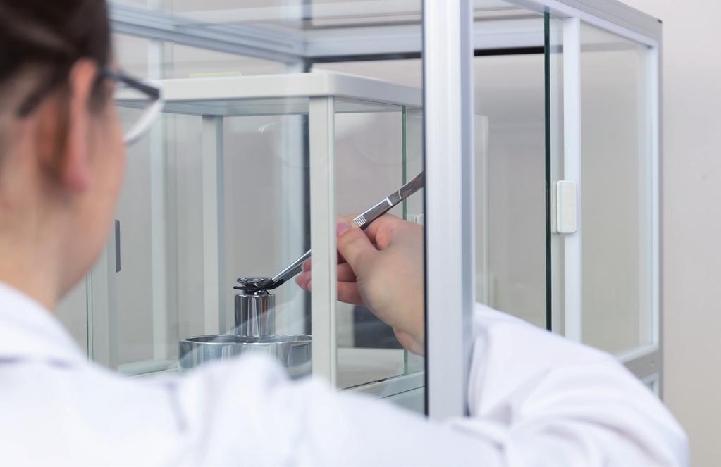
120
Traceable Mass Determination and Uncertainty Calculation
 Traceable Mass Determination and Uncertainty Calculation Falko Hilbrunner, Thomas Fehling, Siego Mühlich, Mario Schreiber Sartorius Lab Instruments GmbH Weender Landstrasse 94-108 Goettingen, Germany ABSTRACT
OIML D 28 DOCUMENT. Edition 2004 (E) ORGANISATION INTERNATIONALE INTERNATIONAL ORGANIZATION. Conventional value of the result of weighing in air
 ORGANISATION INTERNATIONALE INTERNATIONAL ORGANIZATION. Conventional value of the result of weighing in air") INTERNATIONAL DOCUMENT OIML D 28 Edition 2004 (E) Conventional value of the result of weighing in air Valeur conventionnelle du résultat des pesées dans l'air OIML D 28 Edition 2004 (E) ORGANISATION INTERNATIONALE
INTERNATIONAL DOCUMENT OIML D 28 Edition 2004 (E) Conventional value of the result of weighing in air Valeur conventionnelle du résultat des pesées dans l'air OIML D 28 Edition 2004 (E) ORGANISATION INTERNATIONALE
Guidelines on the Calibration of Automatic Instruments for Weighing Road Vehicles in Motion and Measuring Axle Loads AWICal WIM Guide May 2018
 Guidelines on the Calibration of Automatic Instruments for Weighing Road Vehicles in Motion and Measuring Axle Loads AWICal WIM Guide May 2018 Guidelines on the Calibration of Automatic Instruments for
High Precision Mass Measurement in Automation Tatjana Ivanova 1, Jānis Rudzītis 2
 Solid State Phenomena Vol. 164 (2010) pp 19-24 Online available since 2010/Jun/30 at www.scientific.net (2010) Trans Tech Publications, Switzerland doi:10.4028/www.scientific.net/ssp.164.19 High Precision
TYPICAL PRESSURE MEASUREMENT UNCERTAINTY DEFINED BY AN FPG8601 FORCE BALANCED PISTON GAUGE
 TYPICAL PRESSURE MEASUREMENT UNCERTAINTY DEFINED BY AN FPG8601 FORCE BALANCED PISTON GAUGE Michael Bair and Pierre Delajoud 2002 DEC 10 Revised 2004 MAR 26 FORWARD FPG8601 is a pressure standard designed
METHODS FOR CERTIFYING MEASUREMENT EQUIPMENT. Scott Crone
 METHODS FOR CERTIFYING MEASUREMENT EQUIPMENT Scott Crone North American Sales Manager AMETEK Calibration Instruments 8600 Somerset Drive Largo, Florida 33773 USA INTRODUCTION Like any other piece of equipment,
On the redefinition of the kilogram. Dr Philippe RICHARD
 On the redefinition of the kilogram Dr Philippe RICHARD Agenda 1. Recent history of IPK and new SI 2. The CCM conditions 3. The joint CCM and CCU roadmap 4. The mise en pratique of the definition of the
A Unified Approach to Uncertainty for Quality Improvement
 A Unified Approach to Uncertainty for Quality Improvement J E Muelaner 1, M Chappell 2, P S Keogh 1 1 Department of Mechanical Engineering, University of Bath, UK 2 MCS, Cam, Gloucester, UK Abstract To
Guidelines on the Calibration of Non-Automatic Weighing Instruments
 European Association of National Metrology Institutes Guidelines on the Calibration of Non-Automatic Weighing Instruments EURAMET/cg-18/v.01 Previously EA-10/18 July 007 Calibration Guide EURAMET/cg-18/v.01
UNCERTAINTY ANALYSIS FOR LABORATORY ACCREDITATION. Peter B. Crisp. Fluke Precision Measurement Ltd, 52 Hurricane Way, Norwich, UK
 UNCERTAINTY ANALYSIS FOR LABORATORY ACCREDITATION Peter B. Crisp Fluke Precision Measurement Ltd, 5 Hurricane Way, Norwich, UK Introduction NAMAS Accredited laboratories are required to follow recommended
PC TOOL FOR DATA ANALYSIS IN CALIBRATION OF SPECIAL WEIGHTS
 XIX IMEKO World Congress Fundamental and Applied Metrology September 611, 009, Lisbon, Portugal PC TOOL FOR DATA ANALYSIS IN CALIBRATION OF SPECIAL WEIGHTS Adriana Vâlcu 1, Sterică Baicu 1 National Institute
Automated volume measurement for weihts using acoustic volumeter
 IMEKO 20th TC3, 3rd TC16 and 1st TC22 International Conference Cultivating metrological knowledge 27th to 30th November, 2007. Merida, Mexico. Automated volume measurement for weihts using acoustic volumeter
EA Guidelines on the Calibration of Temperature Indicators and Simulators by Electrical Simulation and Measurement
 Publication Reference EA-10/11 EA Guidelines on the Calibration of Temperature Indicators and Simulators by Electrical PURPOSE This document has been produced by EA as a means of giving advice for calibrating
Morehouse. Edward Lane, Morehouse Instrument Company 1742 Sixth Ave York, PA PH: web: sales:
 Morehouse 1 Morehouse Edward Lane, Morehouse Instrument Company 1742 Sixth Ave York, PA 17403 PH: 717-843-0081 web: www.mhforce.com sales: edlane@mhforce.com 2 This presentation will cover the calibration
Air Density Determination Using 1 kg Buoyancy Mass Comparison(III)
") Air Density Determination Using 1 kg Buoyancy Mass Comparison(III) Jin-Wan CHUNG, Kyung-Ho CHANG, Woo-Gab LEE, Kwang-Pyo KIM Division of Physical Metrology, Korea Research Institute of Standards and Science(KRISS)
Air Density Determination Using 1 kg Buoyancy Mass Comparison(III) Jin-Wan CHUNG, Kyung-Ho CHANG, Woo-Gab LEE, Kwang-Pyo KIM Division of Physical Metrology, Korea Research Institute of Standards and Science(KRISS)
Loadcell Calibration - Evaluation of Uncertainties
 Loadcell Calibration - Evaluation of Uncertainties This document is a revision of the evaluation issued in June 2015. Novatech s calibration laboratory is not UKAS accredited due to the high number of
Uncertainty Propagation for Force Calibration Systems
 Uncertainty Propagation for Force Calibration Systems Morehouse Instruments Figure 1. Measurement Uncertainty Pyramid Introduction There are several labs operating throughout the world, whom do not follow
The Fundamentals of Moisture Calibration
 The Fundamentals of Moisture The following guide will provide you with a basic knowledge of humidity calibration, help you to understand your requirements and select an appropriate solution. 1 Why Humidity
Calibration of Analog Scales Based on. a Metrological Comparison Between. the SIM Guide and OIML R 76-1
 Contemporary Engineering Sciences, Vol. 11, 2018, no. 82, 4049-4057 HIKARI Ltd, www.m-hikari.com https://doi.org/10.12988/ces.2018.88447 Calibration of Analog Scales Based on a Metrological Comparison
MASS DETERMINATION OF SILICON SPHERES USED FOR THE AVOGADRO PROJECT
 MASS DETERMINATION OF SILICON SPHERES USED FOR THE AVOGADRO PROJECT Michael Borys, Michael Gläser, Michael Mecke Physikalisch-Technische Bundesanstalt (PTB), Germany ABSTRACT Spheres made of a silicon
Technical Procedure for Measurement Assurance
 Technical Procedure for Measurement Assurance 1.0 Purpose - This procedure specifies the required elements for measurement assurance in the Drug Chemistry Sections of the State Crime Laboratory. 2.0 Scope
A61-02 CALA Guidance on Traceability Revision 1.2 October 15, 2012
 Revision 1.2 October 15, 2012 PAGE II TABLE OF CONTENTS TABLE OF CONTENTS... 1 GUIDANCE...2 1.0 Introduction... 2 2.0 Uncertainty and Traceability... 2 3.0 Need for Traceability... 3 3.1 What does traceability
Kilogram: new definition, selected mises-en-pratique and direct link with SMD activities
 Kilogram: new definition, selected mises-en-pratique and direct link with SMD activities Mieke Coenegrachts WMD 2018 Outline Mass at the SMD - ENS Definition of the kilogram Present New Practical realization
EA-10/13. EA Guidelines on the Calibration of Temperature Block Calibrators. Publication Reference PURPOSE
 Publication Reference EA-10/13 EA Guidelines on the Calibration of Temperature Block Calibrators PURPOSE This document been produced by EA to improve the harmonisation in the calibration of temperature
Calibration and verification: Two procedures having comparable objectives and results
 Calibration and verification: Two procedures having comparable objectives and results KLAUS-DIETER SOMMER, Landesamt für Messund Eichwesen Thüringen (LMET), Germany SAMUEL E. CHAPPELL, Consultant, Formerly
R SANAS Page 1 of 7
 ESTIMATION OF THE UNCERTAINTY OF MEASUREMENT BY CALIBRATION LABORATORIES AND SPECIFICATION OF CALIBRATION AND MEASUREMENT CAPABILITY ON SCHEDULES OF ACCREDITATION Approved By: Chief Executive Officer:
SAMPLE. Accuracy Calibration Certificate. Mettler Toledo 1900 Polaris Parkway Contact: Instrument Type: EURAMET cg-18 v. 4.0 Sample ACC WI v.1.
 076-00-067-ACC-S Mettler Toledo, LLC 900 Polaris Parkway Columbus, OH 0.800.METTLER Customer SAMPLE Accuracy Calibration Certificate Company: Address: City: Zip / Postal: State / Province: Mettler Toledo
Mass determination of 1 kg silicon spheres for Avogadro project
 IMEKO 20 th TC3, 3 rd TC16 and 1 st TC22 International Conference Cultivating metrological knowledge 27 th to 30 th November, 2007. Merida, Mexico. Mass determination of 1 kg silicon spheres for Avogadro
SAMPLE. Accuracy Calibration Certificate. Instrument Type: EURAMET cg-18 v. 4.0 Sample ACC ISO17025 WI v.1.0
 076-0-067-ACC-USL-S Mettler Toledo, LLC 900 Polaris Parkway Columbus, OH 0.800.METTLER Customer Accredited by the American Association for Laboratory Accreditation (ALA) CALIBRATION CERT #788.0 SAMPLE
Accuracy Calibration Certificate
 gl06-0-067-acc Mettler Toledo Service Business Unit Industrial 900 Polaris Parkway Columbus, OH 0-800-- Services Provided By: Customer Accuracy Calibration Certificate Company: Sample Company Test Address:
The General Conference on Weights and Measures (CGPM), at its 24th meeting,
, at its 24th meeting,") On the possible future revision of the International System of Units, the SI Resolution 1 The General Conference on Weights and Measures (CGPM), at its 24th meeting, considering the international consensus
On the possible future revision of the International System of Units, the SI Resolution 1 The General Conference on Weights and Measures (CGPM), at its 24th meeting, considering the international consensus
Comparison of measurement uncertainty budgets for calibration of sound calibrators: Euromet project 576
 NPL REPORT CMAM 73 Comparison of measurement uncertainty budgets for calibration of sound calibrators: Euromet project 576 Peter Hanes October 2001 The National Physical Laboratory is operated on behalf
Understanding the uncertainties associated with using the 5128A RHapid Cal portable humidity generator
 Understanding the uncertainties associated with using the 5128A RHapid Cal portable humidity generator Introduction Humidity generators are mechanical devices that provide stable temperature and humidity
Typical pressure measurement uncertainty defined by an FPG8601 Force Balanced Piston Gauge
 Typical pressure measurement uncertainty defined by an FPG8601 Force Balanced Piston Gauge 2090TN05 Revised 2004 March 26 Technical Note FPG8601 is a pressure standard designed to cover the range from
DESIGN, DEVELOPMENT, AND COMMISSIONING OF A 120 kn DEADWEIGHT FORCE STANDARD MACHINE
 DESIGN, DEVELOPMENT, AND COMMISSIONING OF A 120 kn DEADWEIGHT FORCE STANDARD MACHINE Andy Knott National Physical Laboratory, United Kingdom ABSTRACT This paper describes the development of a 120 kn deadweight
Withdrawn at December 31, Guideline DKD-R 5-7. Calibration of Climatic Chambers DEUTSCHER KALIBRIERDIENST
 DEUTSCHER KALIBRIERDIENST Guideline DKD-R 5-7 Calibration of Climatic Chambers Edition 07/2004 English translation 02/2009 Page 1 of 31 Published by the Accreditation Body of the Deutscher Kalibrierdienst
EVALUATION OF ADSORPTION EFFECT BY USING SILICON SPHERE AND SILICON SURFACE ARTEFACTS
 XVIII IMEKO WORLD CONGRESS Metrology for a Sustainable Development September, 17 22, 2006, Rio de Janeiro, Brazil EVALUATION OF ADSORPTION EFFECT BY USING SILICON SPHERE AND SILICON SURFACE ARTEFACTS Jin
Schedule of Accreditation issued by United Kingdom Accreditation Service 2 Pine Trees, Chertsey Lane, Staines-upon-Thames, TW18 3HR, UK
 Laboratory locations: Schedule of Accreditation 2 Pine Trees, Chertsey Lane, Staines-upon-Thames, TW18 3HR, UK Unit 1G Kilroot Business Park Carrickfergus Co Antrim BT38 7PR Contact: Mr R E Hughes Tel:
Proposed change to the definition of the kilogram: Consequences for legal metrology
 SI UNITS Proposed change to the definition of the kilogram: Consequences for legal metrology RICHARD DAVIS Consultant, International Bureau of Weights and Measures (BIPM) The General Conference on Weights
Calibration of Temperature Block Calibrators
 European Association of National Metrology Institutes Calibration of Temperature Block Calibrators EURAMET cg-13 Version 2.0 (03/2011) Previously EA-10/13 Calibration Guide EURAMET cg-13 Version 2.0 (03/2011)
CALIBRATION CERTIFICATE # 503
 CALIBRATION CERTIFICATE # 503 Calibration date : 2011-02-23 Certificate issued : 2012-04-18 Company name Company address City, Province, Canada CLAS 2009-02 Calibration of Mass flow meter Micro Motion
Calibration Traceability Guidelines
 Calibration Traceability Guidelines Check the website of accrediting bodies for the accredited laboratories individual scope of accreditation www.a2la.org ts.nist.gov/standards/accreditation/index.cfm
PTB S 16.5 MN HYDRAULIC AMPLIFICATION MACHINE AFTER MODERNIZATION
 IMEKO 22 nd TC3, 15 th TC5 and 3 rd TC22 International Conferences 3 to 5 February, 2014, Cape Town, Republic of South Africa PTB S 16.5 MN HYDRAULIC AMPLIFICATION MACHINE AFTER MODERNIZATION R. Kumme
Guidelines on the Calibration of Static Torque Measuring Devices
 European Association of National Metrology Institutes Guidelines on the Calibration of Static Torque Measuring Devices EURAMET/cg-14/v.01 Previously EA-10/14 July 2007 Calibration Guide EURAMET/cg-14/v.01
+ + ( indicator ) + (display, printer, memory)
 + (display, printer, memory)") CERTIFICATION OF STRAIN GAUGE LOAD CELL FAMILIES B. Meissner Physikalisch-Technische Bundesanstalt Weighing Instruments Laboratory 38116 Braunschweig, Germany Abstract: Testing and certification of load
CERTIFICATION OF STRAIN GAUGE LOAD CELL FAMILIES B. Meissner Physikalisch-Technische Bundesanstalt Weighing Instruments Laboratory 38116 Braunschweig, Germany Abstract: Testing and certification of load
MASS AND VOLUME COMPARISONS AT MIKES
 MITTATEKNIIKAN KESKUS CENTRE FOR METROLOGY AND ACCREDITATION Julkaisu J4/2000 MASS AND VOLUME COMPARISONS AT MIKES Additional results to the EA intercomparison of weights 1 mg 100 g (Ma1) and to the EUROMET
Technical Note A Quantification and NIST Traceability of Micromatter Thin Film Standards for XRF Analysis. Version March 16, 2017
 MICROMATTER TECHNOLOGIES INC. #1-8333 130 th Street, Surrey, B.C. V3W 7X4, Canada Phone: +1.604.594.9720 or 1.866.966.2286 Fax: +1.604.594.9726 info@micromatter.com www.micromatter.com Technical Note 2015-01A
OA03 UNCERTAINTY OF MEASUREMENT IN CHEMICAL TESTING IN ACCORDANCE WITH THE STANDARD SIST EN ISO/IEC Table of contents
 UNCERTAINTY OF MEASUREMENT IN CHEMICAL TESTING IN ACCORDANCE WITH THE STANDARD SIST EN ISO/IEC 17025 Table of contents 1 GENERAL... 2 2 THE STANDARD SIST EN ISO/IEC 17025... 2 3 SA'S POLICY IN IMPLEMENTING
Document No: TR 12 Issue No: 1
 ESTIMATION OF THE UNCERTAINTY OF MEASUREMENT BY CALIBRATION LABORATORIES AND SPECIFICATION OF CALIBRATION AND MEASUREMENT CAPABILITY ON SCHEDULES OF ACCREDITATION Prepared by: SADCAS Technical Manage Approved
Introduction to the evaluation of uncertainty
 Manual of Codes of Practice for the Determination of Uncertainties in Mechanical Tests on Metallic Materials SECTION 1 Introduction to the evaluation of uncertainty F A Kandil National Physical Laboratory
The Kilogram Redefined:
 The Kilogram Redefined: SI Units and Fundamental Constants Alan Steele, NRC Canada IPAC 18 Vancouver May 2, 2018 The Metre Convention: May 20, 1875 International Treaty that creates the BIPM and launches
Understanding uncertainties associated with the 5128A RHapid-Cal Humidity Generator
 Understanding uncertainties associated with the 5128A RHapid-Cal Humidity Generator Technical Note The Fluke Calibration 5128A RHapid-Cal Humidity Generator provides a portable, stable test environment
CALIBRATION REPORT FOR THERMOHYDROMETER
 CALIBRATION REPORT FOR THERMOHYDROMETER SAMPLE CUSTOMER S/N: XXXXX Report Number: Y205188 Page 1 of 5 Report No. Y205188 ICL CALIBRATION LABORATORIES, INC. ISO/IEC 17025 and ANSI/NCSL Z540-1 accredited
Ingvar Lindgren Symposium: New Trends in Atomic Physics II 2 3 June 2006 The Quantum SI: A possible new International System of Units
 Ingvar Lindgren Symposium: New Trends in Atomic Physics II 2 3 June 2006 The Quantum SI: A possible new International System of Units Peter Mohr National Institute of Standards and Technology Gaithersburg,
Specific Accreditation Guidance. Infrastructure and Asset Integrity. Measurement Uncertainty in Geotechnical Testing
 Specific Accreditation Guidance Infrastructure and Asset Integrity Measurement Uncertainty in Geotechnical Testing January 2018 Copyright National Association of Testing Authorities, Australia 2018 This
Good practice guide containing experimental results and recommendations for the selection, preparation and calibration of the temperature sensors
 Good practice guide containing experimental results and recommendations for the selection, preparation and calibration of the temperature sensors 1. Scope... 2 2. Introduction... 2 3. Selection of thermocouples
TRACEABILITY AND CAPABILITY CONTROL OF MASS MEASUREMENT EQUIPMENT AND DRIFT STATISTICAL ANALYSIS OF NATIONAL MASS STANDARDS IN LATVIA
 Traceability and capability control of mass measurement equipment and drift statistical analysis of national mass in atvia TRACEABIITY AND CAPABIITY CONTRO OF MA MEAUREMENT EQUIPMENT AND DRIFT TATITICA
Final Report on APMP.M.M-K4.1 - Bilateral Comparison of 1 kg Stainless Steel Mass Standards between KRISS and A*STAR
 Final Report on APMP.M.M-K4.1 - Bilateral Comparison of 1 kg Stainless Steel Mass Standards between KRISS and A*STAR Jin Wan Chung 1, Shih Mean Lee, Sungjun Lee 1 1 Korea Research Institute of Standards
THE NEW WATT BALANCE EXPERIMENT AT METAS
 XX IMEKO World Congress Metrology for Green Growth September 9 14, 2012, Busan, Republic of Korea THE NEW WATT BALANCE EXPERIMENT AT METAS H. Baumann, A. Eichenberger, B. Jeckelmann, Ch. Beguin +, R. Clavel,
National Physical Laboratory New Delhi
 METROLOGY AND MEASUREMENT SYSTEMS VOL. XIV, NUMBER 3 (2007) SANJAY YADAV National Physical Laboratory New Delhi e-mail: syadav@mail.nplindia.ernet.in CHARACTERIZATION OF DEAD WEIGHT TESTERS AND COMPUTATION
STATISTICAL PROCESS CONTROL - THE IMPORTANCE OF USING CALIBRATED MEASUREMENT EQUIPMENT. CASE STUDY
 Proceedings of the 6th International Conference on Mechanics and Materials in Design, Editors: J.F. Silva Gomes & S.A. Meguid, P.Delgada/Azores, 26-30 July 2015 PAPER REF: 5376 STATISTICAL PROCESS CONTROL
Load Cell Approval Field and Laboratory Evaluation Manual
 Load Cell Approval Field and Laboratory Evaluation Category: MASS Revision: c Page: 1 of 9 In 2011 Measurement Canada began phasing in requirements for using approved load cells in selected Heavy Capacity
Metrol. Meas. Syst., Vol. XVIII (2011), No. 2, pp METROLOGY AND MEASUREMENT SYSTEMS. Index , ISSN
, No. 2, pp METROLOGY AND MEASUREMENT SYSTEMS. Index , ISSN") Metrol. Meas. Syst., Vol. XVIII (2011), No. 2, pp. 323 334 METROLOGY AND MEASUREMENT SYSTEMS Index 330930, ISSN 0860-8229 www.metrology.pg.gda.pl INDUCTIVE SENSOR FOR WEIGHING OF MASS Janusz Lewandowski
Metrol. Meas. Syst., Vol. XVIII (2011), No. 2, pp. 323 334 METROLOGY AND MEASUREMENT SYSTEMS Index 330930, ISSN 0860-8229 www.metrology.pg.gda.pl INDUCTIVE SENSOR FOR WEIGHING OF MASS Janusz Lewandowski
POWER UNDERSTANDING MEASUREMENT UNCERTAINTY IN DP FLOW DEVICES
 Proceedings of the ASME 2014 Power Conference POWER2014 July 28-31, 2014, Baltimore, Maryland, USA POWER2014-32205 UNDERSTANDING MEASUREMENT UNCERTAINTY IN DP FLOW DEVICES Michael S. Hering Rosemount DP
ERROR LIMITS AND MEASUREMENT UNCERTAINTY IN LEGAL METROLOGY
 ERROR LIMITS AND MEASUREMENT UNCERTAINTY IN LEGAL METROLOGY K.-D. Sommer 1, M. Kochsiek and W. Schulz 1 Landesamt fuer Mess- und Eichwesen Thueringen, German Phsikalisch-Technische Bundesanstalt, German
Essentials of expressing measurement uncertainty
 Essentials of expressing measurement uncertainty This is a brief summary of the method of evaluating and expressing uncertainty in measurement adopted widely by U.S. industry, companies in other countries,
Establishing traceability and estimating measurement uncertainty in physical, chemical and biological measurements
 Establishing traceability and estimating measurement uncertainty in physical, chemical and biological measurements Experimental Design 8.2.2013 Doc. Martti Heinonen etunimi.sukunimi@mikes.fi Outline 1.
Certification of a High Capacity Force Machine for Testing of Load Cells According to OIML R60
 Certification of a High Capacity Force Machine for Testing of Load Cells According to OIML R60 Bernd Meißner Physikalisch-Technische Bundesanstalt Weighing Instruments Laboratory Braunschweig Abstract
Establishment of a Traceability Chain in Metrology for Materials
 Establishment of a Traceability Chain in Metrology for Materials G. W. Bahng*, Colin Lea** *KRISS, gwbahng@kriss.re.kr, **NPL, cl@npl.co.uk Abstract Materials metrology is becoming an increasingly important
Metallic materials Brinell hardness test. Part 3: Calibration of reference blocks
 INTERNATIONAL STANDARD ISO 6506-3 Third edition 2014-10-01 Metallic materials Brinell hardness test Part 3: Calibration of reference blocks Matériaux métalliques Essai de dureté Brinell Partie 3: Étalonnage
Part 5: Total stations
 Provläsningsexemplar / Preview INTERNATIONAL STANDARD ISO 17123-5 Third edition 2018-02 Optics and optical instruments Field procedures for testing geodetic and surveying instruments Part 5: Total stations
473-SHX Dew Point Mirror
 Humidity and Temperature Reference Hygrometer For Temperature up to 125 C Precise and stable chilled mirror dew point mirror technology High temperature optical components High temperature sample fan Cable
Vocabulary of Metrology
 Vocabulary of Metrology For Understating Uncertainty and Traceability Prepared by: Kim, Sang Ho Engineering Team Leader Modal Shop, Inc A PCB Group Company SI National Metrology Institute Secondary Calibration
CERTIFICATE OF CALIBRATION
 Page 1 of 5 CERTIFICATE OF CALIBRATION 1K Thermistor CERTIFICATE NO.: MANUFACTURER: Measurement Specialties DATE OF CALIBRATION: 26-Apr-17 TC15249 CUSTOMER: AMBIENT TEMPERATURE: (21 ± 3) C JOB NUMBER:
Determination of particle size distribution Single particle light interaction methods. Part 4:
 Provläsningsexemplar / Preview INTERNATIONAL STANDARD ISO 21501-4 Second edition 2018-05 Determination of particle size distribution Single particle light interaction methods Part 4: Light scattering airborne
OIML R 50-3 RECOMMENDATION. Edition 2014 (E) ORGANISATION INTERNATIONALE INTERNATIONAL ORGANIZATION
 ORGANISATION INTERNATIONALE INTERNATIONAL ORGANIZATION") INTERNATIONAL RECOMMENDATION OIML R 50-3 Edition 2014 (E) Continuous totalizing automatic weighing instruments (belt weighers). Part 3: Test report format Instruments de pesage totalisateurs continus à
INTERNATIONAL RECOMMENDATION OIML R 50-3 Edition 2014 (E) Continuous totalizing automatic weighing instruments (belt weighers). Part 3: Test report format Instruments de pesage totalisateurs continus à
2.1. Accuracy, n- how close the indication of the thermometer is to the true value.
 AASHTO Accreditation Policy and Guidance on Thermometer Selection and Records Revised: January 25, 2018 Revision #: 0 1. Objective 1.1. The purpose of this document is to clearly define acceptance criteria
Measurement of Temperature in the Plastics Industry
 Sawi Mess- und Regeltechnik AG CH 8405 Winterthur-Gotzenwil, Switzerland Telephone +41 52 320 50 50, Fax +41 52 320 50 55 www.sawi.ch Measurement of Temperature in the Plastics Industry Johannes Wild,
CERTIFICATE OF CALIBRATION
 Issued By Transmille Ltd. Date of Issue 20 January 2016 0324 Approved Signatory Transmille Ltd. Unit 4, Select Business Centre Lodge Road Staplehurst, Kent. TN12 0QW. TEL 01580 890700 FAX 01580 890711
9.1 Compatibility of modules for nonautomatic weighing instruments (NAWIs) Common requirements
 Common requirements") Übersetzung aus: Verwaltungsvorschriften gesetzliches Messwesen (administrative regulations legal metrology) 9.1 Compatibility of modules for nonautomatic weighing instruments (NAWIs) 9.1.1 Common requirements
Übersetzung aus: Verwaltungsvorschriften gesetzliches Messwesen (administrative regulations legal metrology) 9.1 Compatibility of modules for nonautomatic weighing instruments (NAWIs) 9.1.1 Common requirements
16 Appendix 16 Electrical Research Association Report
 Guide to the Wiring Regulations 16 Appendix 16 Electrical Research Association Report (ERA) report on armoured cables with external CPCs The attached report was commissioned by the ECA and is copyright
Preparation Primary Gas Reference Material (PGRM) by using NIMT Facilities
 by using NIMT Facilities") Preparation Primary Gas Reference Material (PGRM) by using NIMT Facilities By Ms.Ratirat Sinweeruthai June 9-11, 2010 Tsukuba, Japan 8 th APMP/TCQM Gas CRM Workshop Overview Objective of Study EMU of Weighing
Preparation Primary Gas Reference Material (PGRM) by using NIMT Facilities By Ms.Ratirat Sinweeruthai June 9-11, 2010 Tsukuba, Japan 8 th APMP/TCQM Gas CRM Workshop Overview Objective of Study EMU of Weighing
White Paper. Moisture Analyzer Routine Testing
 Moisture Analyzer Routine Testing This white paper describes the influences and sources of error which may be present when conducting moisture analyses. It discusses the routine tests which are necessary
SPECIFIC CRITERIA for CALIBRATION LABORATORIES IN MECHANICAL DISCIPLINE : Force Proving Instruments
 NABL 122-06 NATIONAL ACCREDITATION BOARD FOR TESTING AND CALIBRATION LABORATORIES SPECIFIC CRITERIA for CALIBRATION LABORATORIES IN MECHANICAL DISCIPLINE : Force Proving Instruments Reviewed by MASTER
Explicit-unit formulations of proposed redefinitions of SI base units
 Explicit-unit formulations of proposed redefinitions of SI base units B. P. Leonard The University of Akron, Akron, Ohio, USA 1849 Brookfield Drive, Akron, OH 44313, USA phone: (330) 867-7152 e-mail: bpleona@uakron.edu
EA-10/14. EA Guidelines on the Calibration of Static Torque Measuring Devices. Publication Reference PURPOSE
 Publication Reference EA-10/14 EA Guidelines on the Calibration of Static Torque Measuring Devices PURPOSE This document has been produced by EA to improve harmonisation in determining the calibration
Temperature. 3
 Temperature In 1848, Sir William Thomson (Lord Kelvin) stated the zero principle of dynamics. This principle enabled him to define thermodynamic temperature and to establish an objective method of measuring
Demonstrating Competency and Equivalency of Two Commercial SPRT Calibration Facilities
 Demonstrating Competency and Equivalency of Two Commercial SPRT Calibration Facilities T. J. Wiandt 1,2 1 Fluke Corporation, Hart Scientific Division, American Fork, Utah United States. 2 E-mail: tom.wiandt@hartscientific.com
Standard Practices for Air Speed Calibration Testing
 Standard Practices for Air Speed Calibration Testing Rachael V. Coquilla Bryza Wind Lab, Fairfield, California Air speed calibration is a test process where the output from a wind measuring instrument
Calibration, traceability, uncertainty and comparing measurement results. Workshop 16 March 2015 VSL, Delft The Netherlands
 Calibration, traceability, uncertainty and comparing measurement results Workshop 16 March 2015 VSL, Delft The Netherlands 1 Calibration Calibrating an instrument involves comparing the measurements of
Test Report EN (2008)
") Test Report EN 62233 (2008) Product Name and address of the applicant Name and address of the manufacturer Model Rating Brand name Heating elements for building into floors Advanced Heating Technologies
Test Report EN 62233 (2008) Product Name and address of the applicant Name and address of the manufacturer Model Rating Brand name Heating elements for building into floors Advanced Heating Technologies
Glossary Innovative Measurement Solutions
 Glossary GLOSSARY OF TERMS FOR TRANSDUCERS, LOAD CELLS AND WEIGH MODULES This purpose of this document is to provide a comprehensive, alphabetical list of terms and definitions commonly employed in the
On the possible future revision of the SI
 Bureau International des Poids et Mesures On the possible future revision of the SI Martin Milton (Director) and Michael Stock (Director of Electricity and Mass) BIPM 2 nd July 2013 Bureau International
APPENDIX G EVALUATION OF MEASUREMENT UNCERTAINTY
 APPENDIX G EVALUATION OF MEASUREMENT UNCERTAINTY Table of Contents 1. SCOPE... 2 2. REFERENCES... 2 3. TERMS AND DEFINITIONS... 2 4. BACKGROUND... 4 5. EVALUATION OF MEASUREMENT UNCERTAINTY POLICY... 5
UNCERTAINTY SCOPE OF THE FORCE CALIBRATION MACHINES. A. Sawla Physikalisch-Technische Bundesanstalt Bundesallee 100, D Braunschweig, Germany
 Measurement - Supports Science - Improves Technology - Protects Environment... and Provides Employment - No and in the Future Vienna, AUSTRIA, 000, September 5-8 UNCERTAINTY SCOPE OF THE FORCE CALIBRATION
STANDARD PROCEDURE: NWSP R2 (15) Polyacrylate Superabsorbent Powders Determination of the Particle Size Distribution by Sieve Fractionation
 Polyacrylate Superabsorbent Powders Determination of the Particle Size Distribution by Sieve Fractionation") 1. Scope STANDARD PROCEDURE: Polyacrylate Superabsorbent Powders Determination of the Particle Size Distribution by Sieve Fractionation This test method specifies a method for measuring particle size distributions
1. Scope STANDARD PROCEDURE: Polyacrylate Superabsorbent Powders Determination of the Particle Size Distribution by Sieve Fractionation This test method specifies a method for measuring particle size distributions
OIML R 141 RECOMMENDATION. Edition 2008 (E) ORGANISATION INTERNATIONALE INTERNATIONAL ORGANIZATION
 ORGANISATION INTERNATIONALE INTERNATIONAL ORGANIZATION") INTERNATIONAL RECOMMENDATION OIML R 141 Edition 2008 (E) Procedure for calibration and verification of the main characteristics of thermographic instruments Procédure pour l'étalonnage et la vérification
INTERNATIONAL RECOMMENDATION OIML R 141 Edition 2008 (E) Procedure for calibration and verification of the main characteristics of thermographic instruments Procédure pour l'étalonnage et la vérification
Flowchart for the extraordinary calibrations prior to the redefinition of the kilogram. (BIPM proposal)
") Flowchart for the extraordinary calibrations prior to the redefinition of the kilogram (BIPM proposal) Pauline Barat Michael Stock Alain Picard Richard Davis 1 CIPM informed of intention to use IPK Document
Flowchart for the extraordinary calibrations prior to the redefinition of the kilogram (BIPM proposal) Pauline Barat Michael Stock Alain Picard Richard Davis 1 CIPM informed of intention to use IPK Document
Report on CCM Pilot Study CCM.R-kg-P1. Comparison of future realizations of the kilogram. Final Report
 Report on CCM Pilot Study CCM.R-kg-P1 Comparison of future realizations of the kilogram Final Report 27 June 2017 M. Stock 1, P. Barat 1, F. Beaudoux 2, P. Espel 2, P. Pinot 2, F. Piquemal 2, M. Thomas
Version 4.0 (09/2017) Version 3.0 (02/2015) Version 2.0 (03/2011) Version 1.0 (07/2007) EURAMET e.v. Bundesallee 100 D Braunschweig Germany
 Version 3.0 (02/2015) Version 2.0 (03/2011) Version 1.0 (07/2007) EURAMET e.v. Bundesallee 100 D Braunschweig Germany") Guidelines on the Calibration of Temperature Block Calibrators Authorship and Imprint This document was developed by the EURAMET e.v., Technical Committee for Thermometry. Authors: Yves Hermier (LNE-INM,
Guidelines on the Calibration of Temperature Block Calibrators Authorship and Imprint This document was developed by the EURAMET e.v., Technical Committee for Thermometry. Authors: Yves Hermier (LNE-INM,