Slenderness Effects for Concrete Columns in Sway Frame - Moment Magnification Method
|
|
|
- Dwain Taylor
- 5 years ago
- Views:
Transcription

1 Slenderness Effets for Conrete Columns in Sway Frame - Moment Magnifiation Method

2
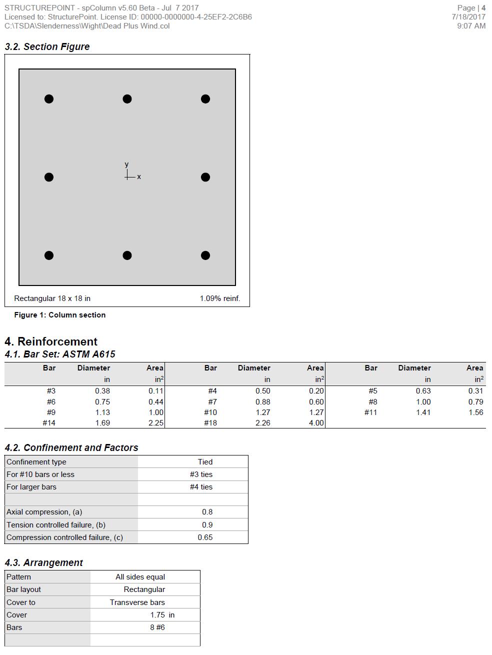
3 Slender Conrete Column Design in Sway Frame Buildings Evaluate slenderness effet for olumns in a sway frame multistory reinfored onrete building by designing the first story exterior olumn. The lear height of the first story is 15 ft-6 in., and is 9 ft. for all of the other stories. Lateral load effets on the building are governed by wind fores. Compare the alulated results with the values presented in the Referene and with exat values from spcolumn engineering software program from StruturePoint. Figure 1 Slender Reinfored Conrete Column Cross-Setion Version: July
4 Contents 1. Fatored Axial Loads and Bending Moments Servie loads Load Combinations Fatored Loads Slenderness Effets and Sway or Nonsway Frame Designation Determine Slenderness Effets Moment Magnifiation at Ends of Compression Member Gravity Load Combination #2 (Gravity Loads Only) Lateral Load Combination #6 (Gravity Plus Wind Loads) Moment Magnifiation along Length of Compression Member Gravity Load Combination #2 (Gravity Loads Only) Load Combination 6 (Gravity Plus Wind Loads) Column Design , a, and strains in the reinforement Fores in the onrete and steel ϕp n and ϕm n Column Interation Diagram - spcolumn Software Summary and Comparison of Design Results Conlusions & Observations Version: July
5 Code Building Code Requirements for Strutural Conrete (ACI ) and Commentary (ACI 318R-14) Referene Reinfored Conrete Mehanis and Design, 7 th Edition, 2016, James Wight, Pearson, Example 12-3 Design Data f = 4,000 psi for olumns f y = 60,000 psi Slab thikness = 6 in. Exterior Columns = 18 in. x 18 in. Interior Columns = 18 in. x 18 in. Interior Beams = 18 in. x 30 in. x 30 ft Exterior Beams = 18 in. x 30 in. x 32 ft Floor superimposed dead load = 20 psf Floor live load = 80 psf Roof superimposed dead load = 25 psf Roof live load = 30 psf Wind loads omputed aording to ASCE 7-10 Total building loads in the first story from the referene: Table 1 Total building fatored loads ASCE 7-10 Referene No. Load Combination P u, kip D 10, D + 1.6L + 0.5L r 11, D + 0.5L L r 10, D + 1.6L r + 0.8W 9, D + 1.6L r - 0.8W 9, D + 0.5L + 0.5L r + 1.6W 10, D + 0.5L + 0.5L r - 1.6W 10, D + 1.6W 7, D - 1.6W 7,065 1
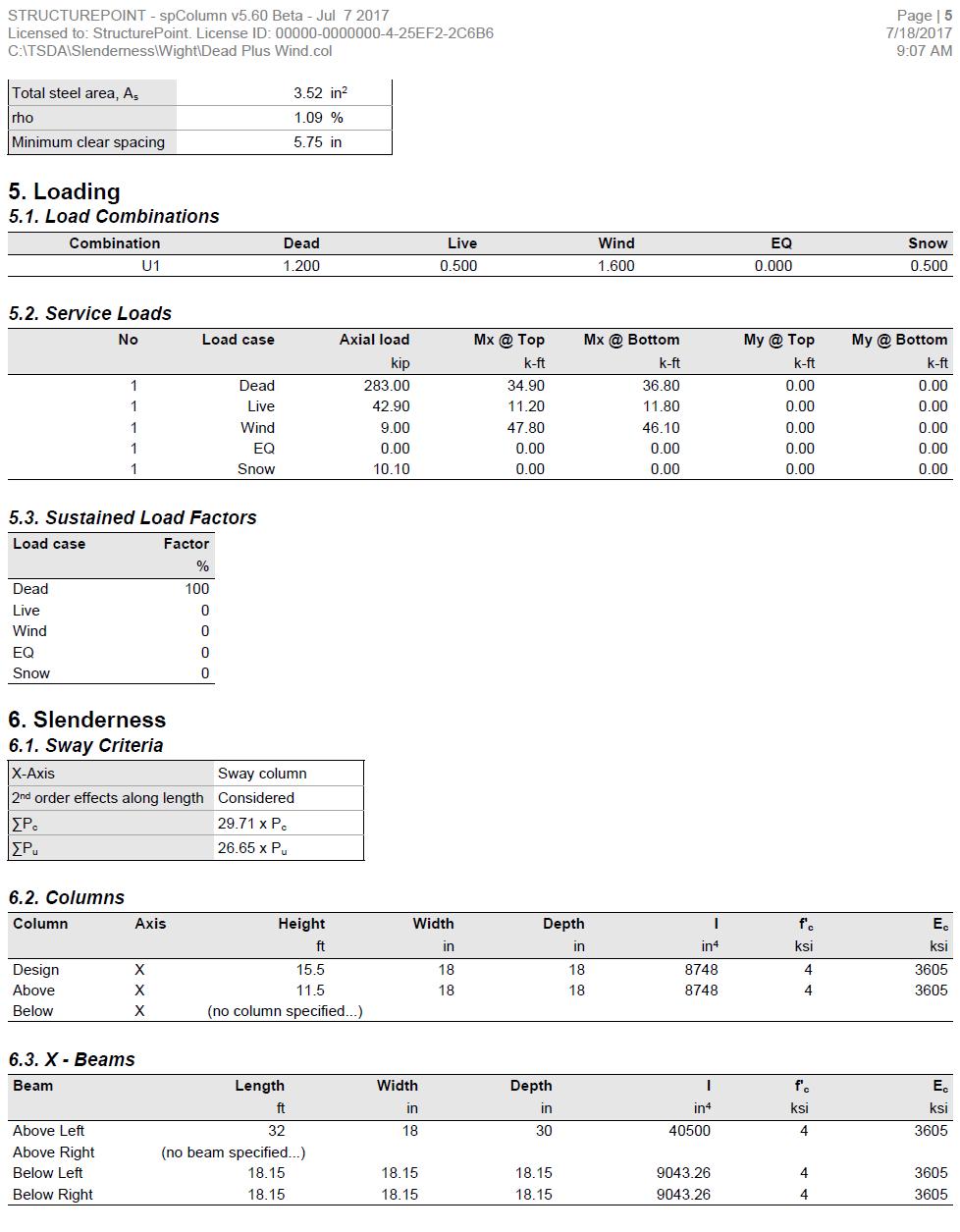
6 1. Fatored Axial Loads and Bending Moments 1.1. Servie loads Table 2 - Exterior olumn servie loads Load Case Axial Load, Bending Moment, ft-kip kip Top Bottom Dead, D Live, L Roof Live, L r Wind, W (N-S) Load Combinations Fatored Loads ASCE 7-10 (2.3.2) ASCE 7-10 Referene No. Load Combination Table 3 - Exterior olumn fatored loads Axial Load, kip Bending Moment, ft-kip Top Bottom M Top,ns ft-kip M Bottom,ns ft-kip D D + 1.6L + 0.5L r M Top,s ft-kip 3 1.2D + 0.5L L r M Bottom,s ft-kip 4 1.2D + 1.6L r + 0.8W D + 1.6L r - 0.8W D + 0.5L + 0.5L r + 1.6W D + 0.5L + 0.5L r - 1.6W D + 1.6W D - 1.6W
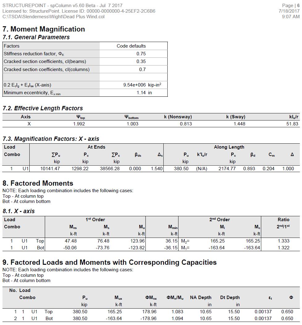
7 2. Slenderness Effets and Sway or Nonsway Frame Designation Columns and stories in strutures are onsidered as nonsway frames if the inrease in olumn end moments due to seond-order effets does not exeed 5% of the first-order end moments, or the stability index for the story (Q) does not exeed ACI ( ) P u is the total vertial load in the first story orresponding to the lateral loading ase for whih P u is greatest (without the wind loads, whih would ause ompression in some olumns and tension in others and thus would anel out). ACI ( and R ) V us is the fatored horizontal story shear in the first story orresponding to the wind loads, and Δ o is the first-order relative defletion between the top and bottom of the first story due to V us. ACI ( and R ) From Table 1, load ombination ( No. 2) provides the greatest value of P u. P 1.2 D 1.6 L 0.5 L 11, 400 kip ASCE 7-10 ( ) u r Sine there is no lateral load in this load ombination, the referene applied an arbitrary lateral load representing (V us) at the top of the first story and alulated the resulting story lateral defletion (Δ o). V 20 kip (given) us in. (given) o Pu o 11, Q V l us ACI (Eq ) Thus, the frame at the first story level is onsidered sway. 3
8 3. Determine Slenderness Effets Iolumn ,124 in. ACI (Table (a)) E ACI ( b) ' 57,000 f 57,000 4,000 3,605 ksi For the olumn below level 2: E I l olumn 3,605 6, in.kip 18 For the olumn above level 2: E I l olumn 3,605 6, in.kip 11.5 For beams framing into the olumns: E b I l b beam 3,605 14, in.kip 3212 Where: E b ACI ( b) ' 57, 000 f 57, , 605 ksi I bh beam ,175 in. ACI (Table (a)) EI l olumns A 1.97 EI 133 l beams ACI (Figure R6.2.5) 1.0 (Column onsidered fixed at the base) ACI (Figure R6.2.5) B Using Figure R6.2.5 from ACI k = 1.44 as shown in the figure below for the exterior olumn. 4
9 Figure 2 Effetive Length Fator (k) for Exterior Column (Sway Frame) kl u r Consider Slenderness ACI (6.2.5a) Where: I g r radius of gyration = ( a) or (b) ACI ( ) A g 4 I g 18 /12 r in. 2 A 18 g 4. Moment Magnifiation at Ends of Compression Member A detailed alulation for load ombinations 2 and 6 is shown below to illustrate the slender olumn moment magnifiation proedure. Table 4 summarizes the magnified moment omputations for the exterior olumns Gravity Load Combination #2 (Gravity Loads Only) M M M ACI ( b) 2 2ns s 2s Where: MTop _ s MBottom _ s M2_ s 0ft.kip 5
10 M M 2 2ns M nd M _2 Top, ns 59.8 ft.kip Top M nd M _2 Bottom, ns 63 ft.kip Bottom M max M, M M 63 ft.kip M M 63 ft.kip nd nd nd nd st st 2 _ 2 Top _ 2 Bottom _ 2 Bottom _ 2 2 _1 Bottom _1 M min M, M M 59.8 ft.kip M M 59.8 ft.kip nd nd nd nd st st 1_ 2 Top _ 2 Bottom _ 2 Top _ 2 1_1 Top _1 P u = 413.3kip 4.2. Lateral Load Combination #6 (Gravity Plus Wind Loads) M M M ACI ( b) 2 2ns s 2s Where: 1 (a) 1 Q 1 s moment magnifier (b) P u P () Seond-order elasti analysis ACI ( ) There are three options for alulating δ s. ACI ( (b)) will be used sine it does not require a detailed strutural analysis model results to proeed and is also used by the solver engine in spcolumn. P u is the summation of all the fatored vertial loads in the first story, and P is the summation of the ritial bukling load for all sway-resisting olumns in the first story. 2 u 2 EI eff P ACI ( ) kl Where: EI eff 0.4EI g (a) 1 ds 0.2E I E I (b) 1 ds EI () 1 ds g s se ACI ( ) There are three options for alulating the effetive flexural stiffness of slender onrete olumns (EI) eff. The seond equation provides aurate representation of the reinforement in the setion and will be used in this example and 6
11 is also used by the solver in spcolumn. Further omparison of the available options is provided in Effetive Flexural Stiffness for Critial Bukling Load of Conrete Columns tehnial note Iolumn 8,748 in. ACI (Table (a)) E ACI ( a) ' 57, 000 f 57, , 605 ksi β ds is the ratio of maximum fatored sustained shear within a story to the maximum fatored shear in that story assoiated with the same load ombination. The maximum fatored sustained shear in this example is equal to zero leading to β ds = 0. ACI ( ) For exterior olumns with one beam framing into them in the diretion of analysis (8 olumns): With 8-#6 reinforement equally distributed on all sides I se = in. 4 (Ref. uses approximate value of 150 in. 4 in lieu of exat value alulated by spcolumn). EI eff 0.2E I E I 1 g s se ds ACI ( (b)) 0.23, 6058, , EI kip-in. eff k = 1.44 (alulated previously). 2 6 P ,313 kip For exterior olumns with two beams framing into them in the diretion of analysis (8 olumns): EI l olumns A 0.95 EI l beams ACI (Figure R6.2.5) 1.0 (Column essentially fixed at base) ACI (Figure R6.2.5) B Using Figure R6.2.5 from ACI k = 1.31 as shown in the figure below for the exterior olumns with two beams framing into them in the diretions of analysis. 7
12 Figure 3 Effetive Length Fator (k) for Exterior Columns with Two Beams Framing into them in the Diretion of Analysis 2 6 P ,586 kip For interior olumns (8 olumns): EI l olumns A 0.95 EI l beams ACI (Figure R6.2.5) 1.0 (Column essentially fixed at base) ACI (Figure R6.2.5) B Using Figure R6.2.5 from ACI k = 1.31 as shown in the figure below for the interior olumns. 8
13 Figure 4 Effetive Length Fator (k) Calulations for Interior Columns With 8-#8 reinforement equally distributed on all sides I se = in. 4 EI eff 0.2E I E I 1 g s se ds ACI ( (b)) 0.23,605 6,124 29, kip-in EI eff 2 6 P ,977 kip P n P n P n P ,313 81,586 81,977 39, 005 kip P 10,100 kip (Table 1) P u 1 s Pu P ACI ( (b)) 1 s = , ,005 smtop, s ft.kip 9
14 M M M ACI ( ) _2,, ft.kip Top nd Top ns s Top s sm, ft.kip Bottom s M M M ACI ( ) _2,, ft.kip Bottom nd Bottom ns s Bottom s M max M, M M ft.kip M M ft.kip nd nd nd nd st st 2 _ 2 Top _ 2 Bottom _ 2 Top _ 2 2 _1 Top _1 M min M, M M ft.kip M M ft.kip nd nd nd nd st st 1_ 2 Top _ 2 Bottom _ 2 Bottom _ 2 1_1 Bottom _1 P u = kip A summary of the moment magnifiation fators and magnified moments for the exterior olumn for all load ombinations using both equation options ACI ( (a)) and ( (b)) to alulate δ s is provided in the table below for illustration and omparison purposes. Note: The designation of M 1 and M 2 is made based on the seond-order (magnified) moments and not based on the first-order (unmagnified) moments. Table 4 - Fatored Axial loads and Magnified Moments at the Ends of Exterior Column No. Load Combination Axial Load, Using ACI (a) Using ACI (b) kip δ s M 1, ft-kip M 2, ft-kip δ s M 1, ft-kip M 2, ft-kip 1 1.4D * * * D + 1.6L + 0.5L r D + 0.5L L r * * * D + 1.6L r + 0.8W 363 * * * D + 1.6L r - 0.8W * * * D + 0.5L + 0.5L r + 1.6W D + 0.5L + 0.5L r - 1.6W * * * D + 1.6W * * * D - 1.6W * * * * Not overed by the referene 10
15 5. Moment Magnifiation along Length of Compression Member In sway frames, seond-order effets shall be onsidered along the length of olumns. It shall be permitted to aount for these effets using ACI ( ) (Nonsway frame proedure), where C m is alulated using M 1 and M 2 from ACI ( ) as follows: ACI ( ) M M 2 2 ACI ( ) Where: M 2 = the seond-order fatored moment. Cm magnifiation fator 1.0 Pu P ACI ( ) 2 u 2 EI eff P ACI ( ) kl Where: EI eff 0.4EI g (a) 1 dns 0.2E I E I (b) 1 dns EI () 1 dns g s se ACI ( ) There are three options for alulating the effetive flexural stiffness of slender onrete olumns (EI) eff. The seond equation provides aurate representation of the reinforement in the setion and will be used in this example and is also used by the solver in spcolumn. Further omparison of the available options is provided in Effetive Flexural Stiffness for Critial Bukling Load of Conrete Columns tehnial note Gravity Load Combination #2 (Gravity Loads Only) Iolumn 6,124 in. ACI (Table (a)) E ACI ( a) ' 57, 000 f 57, , 605 ksi β dns is the ratio of maximum fatored sustained axial load to maximum fatored axial load assoiated with the same load ombination. ACI ( ) Pu, sustained kip 11
16 P kip u dns Pu, sustained dns 0.82 P u EI l olumns A 1.97 (Calulated previously) EI 133 l B 1.0 beams (Column essentially fixed at base) ACI (Figure R6.2.5) ACI (Figure R6.2.5) Using Figure R6.2.5(a) from ACI k = 0.81 as shown in the figure below for the exterior olumn. Figure 5 Effetive Length Fator (k) Calulations for Exterior Column (Nonsway) With 8-#6 reinforement equally distributed on all sides I se = in. 4 (Ref. uses approximate value of 150 in. 4 in lieu of exat value alulated by spcolumn). EI eff 0.2E I E I 1 g s se dns ACI ( (b)) 0.23, 605 6,124 29, EI kip-in. eff 12
17 P ,277 kip P kip ASCE 7-10 ( ) u C M 1 m ACI ( a) M 2 M2 M nd 2_ ft.kip (as onluded from setion 4) ACI ( ) M1 M nd 1_ ft.kip (as onluded from setion 4) ACI ( ) Sine the olumn is bent in double urvature, M 1/M 2 is positive. ACI ( ) C m Cm Pu P 1.0 ACI ( ) = ,277 Mmin P h ACI ( ) u Where P u = kip, and h = the setion dimension in the diretion being onsidered = 18 in. M min ft.kip 12 M 59.8 ft.kip M 39.3 ft.kip M 59.8 ft.kip ACI ( ) 1 min 1 M M ACI ( ) 1 1 M ft.kip M ft.kip M 39.3 ft.kip M ft.kip ACI ( ) 2 2,min 2 M M ACI ( ) 2 2 M ft.kip M 1 and M 2 will be onsidered separately to ensure proper omparison of resulting magnified moments against negative and positive moment apaities of unsymmetrial setions as an be seen in the following figure. 13
18 Figure 6 Column Interation Diagram for Unsymmetrial Setion 5.2. Load Combination #6 (Gravity Plus Wind Loads) Iolumn 6,124 in. ACI (Table (a)) E ACI ( a) ' 57, 000 f 57, , 605 ksi β dns is the ratio of maximum fatored sustained axial load to maximum fatored axial load assoiated with the same load ombination. ACI ( ) Pu, sustained kip P kip u dns Pu, sustained dns 0.89 P u EI l olumns A 1.97 (Calulated previously) EI 133 l beams ACI (Figure R6.2.5) 1.0 (Column essentially fixed at base) ACI (Figure R6.2.5) B Using Figure R6.2.5(a) from ACI k = 0.81 With 8-#6 reinforement equally distributed on all sides I se = in. 4 (Ref. uses approximate value of 150 in. 4 in lieu of exat value alulated by spcolumn). 14
19 EI eff 0.2E I E I 1 g s se dns ACI ( (b)) 0.23, 605 6,124 29, EI kip-in. eff P ,192 kip P kip ASCE 7-10 ( ) u C M 1 m ACI ( a) M 2 M2 M nd 2_ ft.kip (as onluded from setion 4) ACI ( ) M1 M nd 1_ ft.kip (as onluded from setion 4) ACI ( ) Sine the olumn is bent in double urvature, M 1/M 2 is positive. ACI ( ) C m Cm Pu P 1.0 ACI ( ) = ,192 Mmin P h ACI ( ) u Where P u = kip, and h = the setion dimension in the diretion being onsidered = 18 in. M min ft.kip 12 M ft.kip M 36.1 ft.kip M ft.kip ACI ( ) 1 min 1 M M ACI ( ) 1 1 M ft.kip M ft.kip M 36.1 ft.kip M ft.kip ACI ( ) 2 2,min 2 M M ACI ( )
20 M ft.kip M 1 and M 2 are onsidered separately to ensure proper omparison of resulting magnified moments against negative and positive moment apaities of unsymmetrial setions. A summary of the moment magnifiation fators and magnified moments for the exterior olumn for all load ombinations using both equation options ACI ( (a)) and ( (b)) to alulate δ s is provided in the table below for illustration and omparison purposes. Table 5 - Fatored Axial loads and Magnified Moments along Exterior Column Length No. Load Combination Axial Load, kip Using ACI (a) Using ACI (b) δ M 1,ft-kip M 2, ft-kip δ M 1, ft-kip M 2, ft-kip 1 1.4D * * * D + 1.6L + 0.5L r D + 0.5L L r * * * D + 1.6L r + 0.8W 363 * * * D + 1.6L r - 0.8W * * * D + 0.5L + 0.5L r + 1.6W D + 0.5L + 0.5L r - 1.6W * * * D + 1.6W * * * D - 1.6W * * * * Not overed by the referene For olumn design ACI 318 requires the seond-order moment to first-order moment ratios should not exeed If this value is exeeded, the olumn design needs to be revised. ACI (6.2.6) 16
21 No. Table 6 - Seond-Order Moment to First-Order Moment Ratios Load Combination Using ACI (a) Using ACI (b) M 1/M 1(1st) M 2/M 2(1st) M 1/M 1(1st) M 2/M 2(1st) 1 1.4D ** ** 1.00 * 1.00 * 2 1.2D + 1.6L + 0.5L r 1.00 * 1.00 * 1.00 * 1.00 * 3 1.2D + 0.5L L r ** ** 1.00 * 1.00 * 4 1.2D + 1.6L r + 0.8W ** ** D + 1.6L r - 0.8W ** ** 1.00 * 1.00 * 6 1.2D + 0.5L + 0.5L r + 1.6W D + 0.5L + 0.5L r - 1.6W ** ** 1.40 < < D + 1.6W ** ** D - 1.6W ** ** 1.40 < < 1.54 * Cutoff value of M min is applied to M 1(1st) and M 2(1st) in order to avoid unduly large ratios in ases where M 1(1st) and M 2(1st) moments are smaller than M min. ** Not overed by the referene 17
22 6. Column Design Based on the fatored axial loads and magnified moments onsidering slenderness effets, the apaity of the assumed olumn setion (18 in. x 18 in. with 8-#6 bars distributed all sides equal) will be heked and onfirmed to finalize the design. A olumn interation diagram will be generated using strain ompatibility analysis, the detailed proedure to develop olumn interation diagram an be found in Interation Diagram Tied Reinfored Conrete Column example. The axial ompression apaity ϕp n for all load ombinations will be set equals to P u, then the moment apaity ϕm n assoiated to ϕp n will be ompared with the magnified applied moment M u. The design hek for load ombination #6 is shown below for illustration. The rest of the heks for the other load ombinations are shown in the following Table. Figure 7 Strains, Fores, and Moment Arms (Load Combination 6) The following proedure is used to determine the nominal moment apaity by setting the design axial load apaity, ϕp n, equal to the applied axial load, P u and iterating on the loation of the neutral axis. 6.1., a, and strains in the reinforement Try in. Where is the distane from the fiber of maximum ompressive strain to the neutral axis. ACI ( ) a in. ACI ( ) Where: ' f ACI (Table ) ACI ( ) u 18
23 f y 60 y E 29, 000 s s ( d1 ) ( ) (Tension) < y tension reinforement has not yielded 0.65 ACI (Table ) ' s 1 ( d2) ( ) (Compression) > y ' h s2 ( ) (Tension) < y Fores in the onrete and steel C f ab ACI ( ) ' , kip f E , 000, , 620 psi s s s T f A 39, kip s y s1 Sine > ompression reinforement has yielded ' s1 y f 1 f 60,000 psi ' s y Sine < ompression reinforement has not yielded ' s2 y ' ' fs2 s2 Es , 000, , 479 psi The area of the reinforement in this layer has been inluded in the area (ab) used to ompute C. As a result, it is neessary to subtrat 0.85f from f s before omputing C s: ' ' ' f f A C , , kip s1 s1 s1 ' ' ' f f A C , , kip s2 s2 s ϕp n and ϕm n Pn C Cs 1Cs 2 Ts kip P kip = P n The assumed value of = in. is orret. u 19
24 h a h h h h M n C Cs 1 d2 Cs2 Ts d M n kip.ft M kip.ft M M kip.ft n u 2 Table 7 Exterior Column Axial and Moment Capaities No. P u, kip M u = M 2(2nd), ft-kip, in. ε t = ε s φ φp n, kip φm n, kip.ft Sine ϕm n > M u for all ϕp n = P u, use 18 x 18 in. olumn with 8-#6 bars. 20

25 7. Column Interation Diagram - spcolumn Software spcolumn program performs the analysis of the reinfored onrete setion onforming to the provisions of the Strength Design Method and Unified Design Provisions with all onditions of strength satisfying the appliable onditions of equilibrium and strain ompatibility and inludes slenderness effets using moment magnifiation method for sway and nonsway frames. For this olumn setion, we ran in investigation mode with ontrol points using the In lieu of using program shortuts, spsetion (Figure 8) was used to plae the reinforement and define the over to illustrate handling of irregular shapes and unusual bar arrangement. Figure 8 spcolumn Model Editor (spsetion) 21

26 Figure 9 spcolumn Model Input Wizard Windows 22
27 Figure 10 Column Setion Interation Diagram about X-Axis Design Chek for Load Combination 6 (spcolumn) 23
28 24
29 25
30 26
31 27
32 28
33 29
34 8. Summary and Comparison of Design Results Analysis and design results from the hand alulations above are ompared for the one load ombination used in the referene (Example 12-3) and exat values obtained from spcolumn model. Table 8 Parameters for Moment Magnifiation along the Column Length Q k β dns C m I se P, kip δ M 2(min), ft-kip M 2(2nd), ft-kip Hand * ,277 1 > Referene ,660 1 > spcolumn ,259 1 > * From nomographs (ACI 318 harts) Conservatively estimated not using exat formulae without impat on the final results in this speial ase Exat formulated answer In this table, a detailed omparison for all onsidered load ombinations are presented for omparison. Table 9 - Fatored Axial loads and Magnified Moments at Column Ends No. P u, kip δ s M 1(2nd), ft-kip M 2(2nd), ft-kip Hand spcolumn Hand spcolumn Hand spcolumn Hand spcolumn N/A N/A N/A N/A N/A N/A
35 Table 10 - Fatored Axial loads and Magnified Moments along Column Length No. δ M 1, ft-kip M 2, ft-kip M 1/M 1(1st) M 2/M 2(1st) Hand spcolumn Hand spcolumn Hand spcolumn Hand spcolumn Hand spcolumn Table 11 - Design Parameters Comparison No., in. ε t = ε s φ φp n, kip φm n, kip.ft Hand spcolumn Hand spcolumn Hand spcolumn Hand spcolumn Hand spcolumn All the results of the hand alulations illustrated above are in preise agreement with the automated exat results obtained from the spcolumn program. 31
36 9. Conlusions & Observations The analysis of the reinfored onrete setion performed by spcolumn onforms to the provisions of the Strength Design Method and Unified Design Provisions with all onditions of strength satisfying the appliable onditions of equilibrium and strain ompatibility and inludes slenderness effets using moment magnifiation method for sway and nonsway frames. ACI 318 provides multiple options for alulating values of k, (EI) eff, δ s, and δ leading to variability in the determination of the adequay of a olumn setion. Engineers must exerise judgment in seleting suitable options to math their design ondition as is the ase in the referene where the author onservatively made assumptions to simplify and speed the alulation effort. The spcolumn program utilizes the exat methods whenever possible and allows user to override the alulated values with diret input based on their engineering judgment wherever it is permissible. In load ombinations 7 and 9, M u inluding seond-order effets exeeds 1.4 M u due to first-order effets (see Table 6). This indiates that in this building, the weight of the struture is high in proportion to its lateral stiffness leading to exessive PΔ effet (seondary moments are more than 25 perent of the primary moments). The PΔ effets will eventually introdue singularities into the solution to the equations of equilibrium, indiating physial strutural instability. It was onluded in the literature that the probability of stability failure inreases rapidly when the stability index Q exeeds 0.2, whih is equivalent to a seondary-to-primary moment ratio of The maximum value of the stability oeffiient θ (aording to ASCE/SEI 7) whih is lose to stability oeffiient Q (aording to ACI 318) is The value 0.25 is equivalent to a seondary-to-primary moment ratio of Hene, the upper limit of 1.4 on the seondary-to-primary moment ratio was seleted by the ACI 318. As an be seen in Table 6 of this example, exploring the impat of other ode permissible equation options provides the engineer added flexibility in deision making regarding design. For load ombinations 7 & 9 resolving the stability onern may be viable through a frame analysis providing values for V us and Δ o to alulate magnifiation fator δ s and may allow the proposed design to be aeptable by inspetion of load ombination #6. Creating a omplete model with detailed lateral loads and load ombinations to aount for seond order effets may not be warranted for all ases of slender olumn design nor is it disadvantageous to have a higher margin of safety when it omes to olumn slenderness and frame stability onsiderations. 32
Slenderness Effects for Concrete Columns in Sway Frame - Moment Magnification Method
 Slenderness Effets for Conrete Columns in Sway Frame - Moment Magnifiation Method Slender Conrete Column Design in Sway Frame Buildings Evaluate slenderness effet for olumns in a sway frame multistory
Slenderness Effects for Concrete Columns in Sway Frame - Moment Magnification Method (CSA A )
") Slenderness Effects for Concrete Columns in Sway Frame - Moment Magnification Method (CSA A23.3-94) Slender Concrete Column Design in Sway Frame Buildings Evaluate slenderness effect for columns in a
Slenderness Effects for Concrete Columns in Sway Frame - Moment Magnification Method (CSA A23.3-94) Slender Concrete Column Design in Sway Frame Buildings Evaluate slenderness effect for columns in a
Case Study in Reinforced Concrete adapted from Simplified Design of Concrete Structures, James Ambrose, 7 th ed.
 ARCH 631 Note Set 11 F015abn Case Study in Reinfored Conrete adapted from Simplified Design of Conrete Strutures, James Ambrose, 7 th ed. Building desription The building is a three-story offie building
A.1. Member capacities A.2. Limit analysis A.2.1. Tributary weight.. 7. A.2.2. Calculations. 7. A.3. Direct design 13
 APPENDIX A APPENDIX A Due to its extension, the dissertation ould not inlude all the alulations and graphi explanantions whih, being not essential, are neessary to omplete the researh. This appendix inludes
Two-Way Flat Slab (Concrete Floor with Drop Panels) System Analysis and Design
 System Analysis and Design") Two-Way Flat Slab (Conrete Floor with Drop Panels) System Analysis and Design Two-Way Flat Slab (Conrete Floor with Drop Panels) System Analysis and Design Design the onrete floor slab system shown below
Two-Way Flat Slab (Conrete Floor with Drop Panels) System Analysis and Design Two-Way Flat Slab (Conrete Floor with Drop Panels) System Analysis and Design Design the onrete floor slab system shown below
Sway Column Example. PCA Notes on ACI 318
 Sway Column Example PCA Notes on ACI 318 ASDIP Concrete is available for purchase online at www.asdipsoft.com Example 11.2 Slenderness Effects for Columns in a Sway Frame Design columns C1 and C2 in the
WRAP-AROUND GUSSET PLATES
 WRAP-AROUND GUSSET PLATES Where a horizontal brae is loated at a beam-to-olumn intersetion, the gusset plate must be ut out around the olumn as shown in Figure. These are alled wrap-around gusset plates.
Chapter 6. Compression Reinforcement - Flexural Members
 Chapter 6. Compression Reinforement - Flexural Members If a beam ross setion is limite beause of arhitetural or other onsierations, it may happen that the onrete annot evelop the ompression fore require
Masonry Beams. Ultimate Limit States: Flexure and Shear
 Masonry Beams 4:30 PM 6:30 PM Bennett Banting Ultimate Limit States: Flexure and Shear Leture Outline 1. Overview (5) 2. Design for Flexure a) Tension Reinforement (40) b) Compression Reinforement (20)
Software Verification
 EC-4-004 Example-001 STEEL DESIGNERS MANUAL SEVENTH EDITION - DESIGN OF SIMPLY SUPPORTED COMPOSITE BEAM EXAMPLE DESCRIPTION Consider an internal seondary omposite beam of 1-m span between olumns and subjet
4.3 Moment Magnification
 CHAPTER 4: Reinforced Concrete Columns 4.3 Moment Magnification Description An ordinary or first order frame analysis does not include either the effects of the lateral sidesway deflections of the column
Reinforced Concrete Design
 Reinfored Conrete Design Notation: a = depth of the effetive ompression blok in a onrete beam A = name for area A g = gross area, equal to the total area ignoring any reinforement A s = area of steel reinforement
Interaction Diagram Dumbbell Concrete Shear Wall Unsymmetrical Boundary Elements
 Interaction Diagram Dumbbell Concrete Shear Wall Unsymmetrical Boundary Elements Interaction Diagram - Dumbbell Concrete Shear Wall Unsymmetrical Boundary Elements Investigate the capacity for the irregular
Reinforced Concrete Design
 Reinfored Conrete Design Notation: a = depth of the effetive ompression blok in a onrete beam A = name for area A g = gross area, equal to the total area ignoring any reinforement A s = area of steel reinforement
BEHAVIOR OF SQUARE CONCRETE-FILLED TUBULAR COLUMNS UNDER ECCENTRIC COMPRESSION WITH DOUBLE CURVATURE DEFLECTION
 Otober 2-7, 28, Beijing, China BEHAVIOR OF SQARE CONCRETE-FILLED TBLAR COLNS NDER ECCENTRIC COPRESSION WITH DOBLE CRVATRE DEFLECTION T. Fujinaga, H. Doi 2 and Y.P. Sun 3 Assoiate Professor, Researh Center
Wood Design. = theoretical allowed buckling stress
 Wood Design Notation: a = name for width dimension A = name for area A req d-adj = area required at allowable stress when shear is adjusted to inlude self weight b = width of a retangle = name for height
twenty steel construction: columns & tension members ARCHITECTURAL STRUCTURES: FORM, BEHAVIOR, AND DESIGN DR. ANNE NICHOLS FALL 2018 lecture
 ARCHITECTURAL STRUCTURES: FORM, BEHAVIOR, AND DESIGN DR. ANNE NICHOLS Cor-Ten Steel Sulpture By Rihard Serra Museum of Modern Art Fort Worth, TX (AISC - Steel Strutures of the Everyday) FALL 2018 leture
Two-Way Concrete Floor Slab with Beams Design and Detailing (CSA A )
") Two-Way Conrete Floor Slab with Beams Design and Detailing (CSA A.-14) Two-Way Conrete Floor Slab with Beams Design and Detailing (CSA A.-14) Design the slab system shown in Figure 1 for an intermediate
Two-Way Conrete Floor Slab with Beams Design and Detailing (CSA A.-14) Two-Way Conrete Floor Slab with Beams Design and Detailing (CSA A.-14) Design the slab system shown in Figure 1 for an intermediate
Analysis of Leakage Paths Induced by Longitudinal Differential Settlement of the Shield-driven Tunneling
 2016 rd International Conferene on Engineering Tehnology and Appliation (ICETA 2016) ISBN: 978-1-60595-8-0 Analysis of Leakage Paths Indued by Longitudinal Differential Settlement of the Shield-driven
Shear-Friction Strength of RC Walls with 550 MPa Bars
 Proeedings of the Tenth Paifi Conferene on Earthquake Engineering Building an Earthquake-Resilient Paifi 6-8 November 215, Sydney, Australia Shear-Frition Strength of RC Walls with 55 MPa Bars Jang-woon
Ch. 10 Design of Short Columns Subject to Axial Load and Bending
 Ch. 10 Design o Short Columns Subjet to Axial Load and Bending Axial Loading and Bending Development o Interation Diagram Column Design Using P-M Interation Diagram Shear in Columns Biaxial Bending Examples
The Hashemite University Department of Civil Engineering ( ) Dr. Hazim Dwairi 1
 Dr. Hazim Dwairi 1") Department of Civil Engineering Letre 8 Slender Colmns Definition of Slender Colmn When the eentri loads P are applied, the olmn deflets laterally by amont δ,, however the internal moment at midheight:
Department of Civil Engineering Letre 8 Slender Colmns Definition of Slender Colmn When the eentri loads P are applied, the olmn deflets laterally by amont δ,, however the internal moment at midheight:
Software Verification
 AISC-360-10 Example 001 COMPOSITE GIRDER DESIGN EXAMPLE DESCRIPTION A typial bay of a omposite floor system is illstrated below. Selet an appropriate ASTM A992 W-shaped beam and determine the reqired nmber
Moment Curvature Characteristics for Structural Elements of RC Building
 Moment Curvature Charateristis for Strutural Elements of RC Building Ravi Kumar C M 1,*, Vimal Choudhary 2, K S Babu Narayan 3 and D. Venkat Reddy 3 1 Researh Sholar, 2 PG Student, 3 Professors, Department
Reinforced Concrete Design
 Reinfored Conrete Design Notation: a = depth of the effetive ompression blok in a onrete beam A = name for area Ag = gross area, equal to the total area ignoring any reinforement As = area of steel reinforement
A Time-Dependent Model For Predicting The Response Of A Horizontally Loaded Pile Embedded In A Layered Transversely Isotropic Saturated Soil
 IOSR Journal of Mehanial and Civil Engineering (IOSR-JMCE) e-issn: 2278-1684,p-ISSN: 232-334X, Volume 16, Issue 2 Ser. I (Mar. - Apr. 219), PP 48-53 www.iosrjournals.org A Time-Dependent Model For Prediting
fib Model Code 2020 Shear and punching provisions, needs for improvements with respect to new and existing structures
 fib Model Code 2020 Shear and punhing provisions, needs for improvements with respet to new and existing strutures Aurelio Muttoni Workshop fib Sao Paulo, 29.9.2017 Éole Polytehnique Fédérale de Lausanne,
The Serviceability Considerations of HSC Heavily Steel Reinforced Members under Bending
 Amerian Journal of Applied Sienes 5 (9): 115-114, 8 ISSN 1546-99 8 Siene Publiations The Servieability Considerations of HSC Heavily Steel Reinfored Members under Bending 1 Ali Akbar ghsoudi and Yasser
ε t increases from the compressioncontrolled Figure 9.15: Adjusted interaction diagram
 CHAPTER NINE COLUMNS 4 b. The modified axial strength in compression is reduced to account for accidental eccentricity. The magnitude of axial force evaluated in step (a) is multiplied by 0.80 in case
Shear Strength of Squat Reinforced Concrete Walls with Flanges and Barbells
 Transations, SMiRT 19, Toronto, August 2007 Shear Strength of Squat Reinfored Conrete Walls with Flanges and Barbells Cevdet K. Gule 1), Andrew S. Whittaker 1), Bozidar Stojadinovi 2) 1) Dept. of Civil,
BEAMS: SHEARING STRESS
 LECTURE Third Edition BEAMS: SHEARNG STRESS A. J. Clark Shool of Engineering Department of Civil and Environmental Engineering 14 Chapter 6.1 6.4 b Dr. brahim A. Assakkaf SPRNG 200 ENES 220 Mehanis of
Design of AAC floor slabs according to EN 12602
 Design of AAC floor slabs aording to EN 160 Example 1: Floor slab with uniform load 1.1 Issue Design of a floor slab under a living room Materials Component with a ompressive strength lass AAC 4,5, densit
Purpose of reinforcement P/2 P/2 P/2 P/2
 Department o Civil Engineering Purpose o reinorement Consider a simpl supported beam: P/2 P/2 3 1 2 P/2 P/2 3 2 1 1 Purpose o Reinorement Steel reinorement is primaril use beause o the nature o onrete
STRUCTURAL BEHAVIOR OF R/C DEEP BEAM WITH HEADED LONGITUDINAL REINFORCEMENTS
 13 th World Conferene on Earthquake Engineering anouver, B.C., Canada August 1-6, 24 Paper No. 58 STRUCTURAL BEHAIOR OF R/C DEEP BEAM WITH HEADED LONGITUDINAL REINFORCEMENTS Soo-Yeon SEO 1, Seung-Joe YOON
Introduction. ENCE 710 Design of Steel Structures IV. COMPOSITE STEEL-CONCRET CONSTRUCTION. Effective Width. Composite Action
 ENCE 710 Design of Steel Strutures V. COMPOSTE STEEL-CONCRET CONSTRUCTON C. C. Fu, Ph.D., P.E. Civil and Environmental Engineering Department University of Maryland ntrodution Following subjets are overed:
PREDICTING THE SHEAR STRENGTH OF CONCRETE STRUCTURES
 PREDICTING THE SHEAR STRENGTH OF CONCRETE STRUCTURES M.P.COLLINS; E.C.BENTZ; P.T.QUACH; A.W.FISHER; G.T. PROESTOS Department of Civil Engineering, University of Toronto, Canada SUMMARY Beause many shear
1. INTRODUCTION. l t t r. h t h w. t f t w. h p h s. d b D F. b b d c. L D s
 Rapid Assessment of Seismi Safety of Elevated ater Tanks with FRAME Staging 1. NTRODUCTON 1.1 ntrodution ater tanks are lifeline items in the aftermath of earthquakes. The urrent pratie of designing elevated
Universities of Leeds, Sheffield and York
 promoting aess to White Rose researh papers Universities of Leeds, Sheffield and York http://eprints.whiterose.a.uk/ This is an author produed version of a paper published in Journal of Composites for
Design of Reinforced Concrete Structures (II)
") Design of Reinforced Concrete Structures (II) Discussion Eng. Mohammed R. Kuheil Review The thickness of one-way ribbed slabs After finding the value of total load (Dead and live loads), the elements are
Design of Reinforced Concrete Structures (II) Discussion Eng. Mohammed R. Kuheil Review The thickness of one-way ribbed slabs After finding the value of total load (Dead and live loads), the elements are
The Design of Fiber Reinforced Polymers for Structural Strengthening An Overview of ACI 440 Guidelines. Sarah Witt Fyfe Company November 7, 2008
 The Design o Fiber Reinored Polymers or Strutural Strengthening An Overview o ACI 440 Guidelines Sarah Witt Fye Company November 7, 2008 1 GUIDE FOR THE DESIGN AND CONSTRUCTION OF EXTERNALLY BONDED FRP
MODELLING THE POSTPEAK STRESS DISPLACEMENT RELATIONSHIP OF CONCRETE IN UNIAXIAL COMPRESSION
 VIII International Conferene on Frature Mehanis of Conrete and Conrete Strutures FraMCoS-8 J.G.M. Van Mier, G. Ruiz, C. Andrade, R.C. Yu and X.X. Zhang Eds) MODELLING THE POSTPEAK STRESS DISPLACEMENT RELATIONSHIP
thirteen wood construction: column design ARCHITECTURAL STRUCTURES: FORM, BEHAVIOR, AND DESIGN DR. ANNE NICHOLS SUMMER 2017 lecture
 ARCHITECTURAL STRUCTURES: FORM, BEHAVIOR, AND DESIGN DR. ANNE NICHOLS SUMMER 2017 leture thirteen wood onstrution: olumn design Wood Columns 1 Compression Members (revisited) designed for strength & stresses
Compression Members Local Buckling and Section Classification
 Compression Memers Loal Bukling and Setion Classifiation Summary: Strutural setions may e onsidered as an assemly of individual plate elements. Plate elements may e internal (e.g. the wes of open eams
Where and are the factored end moments of the column and >.
 11 LIMITATION OF THE SLENDERNESS RATIO----( ) 1-Nonsway (braced) frames: The ACI Code, Section 6.2.5 recommends the following limitations between short and long columns in braced (nonsway) frames: 1. The
INTERNATIONAL JOURNAL OF CIVIL AND STRUCTURAL ENGINEERING Volume 2, No 4, 2012
 INTERNATIONAL JOURNAL OF CIVIL AND STRUCTURAL ENGINEERING Volume, No 4, 01 Copyright 010 All rights reserved Integrated Publishing servies Researh artile ISSN 0976 4399 Strutural Modelling of Stability
STATISTICAL MODEL FOR THE PREDICTION OF SHEAR STRENGTH OF HIGH STRENGTH REINFORCED CONCRETE BEAMS
 STATISTICAL MODEL FOR THE PREDICTION OF SHEAR STRENGTH OF HIGH STRENGTH REINFORCED CONCRETE BEAMS Attaullah Shah* Allama Iqbal Open University Islamabad Pakistan Saeed Ahmad Department of Civil Engineering,
Reinforced Concrete Design
 Reinored Conrete Design Notation: a = depth o the eetive ompression blok in a onrete beam A g = gross area, equal to the total area ignoring any reinorement A s = area o steel reinorement in onrete beam
Simplified Buckling Analysis of Skeletal Structures
 Simplified Bukling Analysis of Skeletal Strutures B.A. Izzuddin 1 ABSRAC A simplified approah is proposed for bukling analysis of skeletal strutures, whih employs a rotational spring analogy for the formulation
Bending resistance of high performance concrete elements
 High Performane Strutures and Materials IV 89 Bending resistane of high performane onrete elements D. Mestrovi 1 & L. Miulini 1 Faulty of Civil Engineering, University of Zagreb, Croatia Faulty of Civil
RC DEEP BEAMS ANALYSIS CONSIDERING LOCALIZATION IN COMPRESSION
 RC DEEP BEAMS ANAYSIS CONSIDERING OCAIZATION IN COMPRESSION Manakan ERTSAMATTIYAKU* 1, Torsak ERTSRISAKURAT* 1, Tomohiro MIKI* 1 and Junihiro NIWA* ABSTRACT: It has been found that RC deep beams usually
NON-LINEAR BENDING CHARACTERISTICS OF PHC PILES UNDER VARYING AXIAL LOAD
 13 th World Conferene on Earthquake Engineering Vanouver, B.C., Canada August 1-6, 24 aper No. 356 NON-LINEAR BENDING CHARACTERISTICS OF HC ILES UNDER VARYING AXIAL LOAD Toshihiko ASO 1 Fusanori MIURA
Flexural Drift Capacity of Reinforced Concrete Wall with Limited Confinement
 ACI STRUCTURAL JOURNAL TECHNICAL PAPER Title no. 110-S10 Flexural Drift Capaity of Reinfored Conrete Wall with Limited Confinement by S. Takahashi, K. Yoshida, T. Ihinose, Y. Sanada, K. Matsumoto, H. Fukuyama,
INFORMATION CONCERNING MATERIALS TO BE USED IN THE DESIGN
 TITLE 5 DESIGN CHAPTER 8 INFORMATION CONCERNING MATERIALS TO BE USED IN THE DESIGN Artile 38. Charateristis o steel or reinorements 38.1 General The harateristis o the steel used or the design desribed
Case Study in Reinforced Concrete adapted from Simplified Design of Concrete Structures, James Ambrose, 7 th ed.
 ARCH 631 Note Set 11 F013abn Case Stdy Refored Conrete adapted from Simplified Design of Conrete Strtres, James Ambrose, 7 th ed. Bildg desription The bildg is a three-story offie bildg tended for spelative
THE EQUATION CONSIDERING CONCRETE STRENGTH AND STIRRUPS FOR DIAGONAL COMPRESSIVE CAPACITY OF RC BEAM
 - Tehnial Paper - THE EQUATION CONSIDERING CONCRETE STRENGTH AND STIRRUPS FOR DIAGONAL COMPRESSIE CAPACITY OF RC BEAM Patarapol TANTIPIDOK *, Koji MATSUMOTO *, Ken WATANABE *3 and Junihiro NIWA *4 ABSTRACT
A NORMALIZED EQUATION OF AXIALLY LOADED PILES IN ELASTO-PLASTIC SOIL
 Journal of Geongineering, Vol. Yi-Chuan 4, No. 1, Chou pp. 1-7, and April Yun-Mei 009 Hsiung: A Normalized quation of Axially Loaded Piles in lasto-plasti Soil 1 A NORMALIZD QUATION OF AXIALLY LOADD PILS
FORCE DISTRIBUTION OF REINFORCED CONCRETE COUPLING BEAMS WITH DIAGONAL REINFORCEMENT
 FORCE DISTRIBUTION OF REINFORCED CONCRETE COULING BEAMS WITH DIAGONAL REINFORCEMENT Yenny Nurhasanah Jurusan Teknik Sipil, Fakultas Teknik, Universitas Muhammadiyah Surakarta Jl. A. Yani Tromol os 1 abelan
UDC DAMAGE DIAGNOSTICS IN A VERTICAL BAR ON THE ELASTIC SUSPENDER WITH CONCENTRATED MASS
 1 UDC 534113 DAAGE DIAGNOSTICS IN A VERTICAL BAR ON THE ELASTIC SUSPENDER WITH CONCENTRATED ASS A Ilgamov, BZ Sultanov, AN Tazhitdinov, AG Khakimov Institute of ehanis, Ufa Branh RAS, Ufa, Russia Using
Development of an efficient finite element model for the dynamic analysis of the train-bridge interaction
 Development of an effiient finite element model for the dynami analysis of the train-bridge interation S. Neves, A. Azevedo & R. Calçada Faulty of Engineering, University of Porto, Porto, Portugal ABSTRACT:
City, University of London Institutional Repository
 City Researh Online City, University of London Institutional Repository Citation: Labib, M., Moslehy, Y. & Ayoub, A. (07). Softening Coeffiient of Reinfored Conrete Elements Subjeted to Three-Dimensional
Uniaxial Concrete Material Behavior
 COMPUTERS AND STRUCTURES, INC., JULY 215 TECHNICAL NOTE MODIFIED DARWIN-PECKNOLD 2-D REINFORCED CONCRETE MATERIAL MODEL Overview This tehnial note desribes the Modified Darwin-Peknold reinfored onrete
SIMULATION OF BEHAVIOR OF REINFORCED CONCRETE COLUMNS SUBJECTED TO CYCLIC LATERAL LOADS
 SIMULATION OF BEHAVIOR OF REINFORCED CONCRETE COLUMNS SUBJECTED TO CYCLIC LATERAL LOADS H. Sezen 1, M.S. Lodhi 2, E. Setzler 3, and T. Chowdhury 4 1,2 Department of Civil and Environmental Engineering
This Technical Note describes how the program checks column capacity or designs reinforced concrete columns when the ACI code is selected.
 COMPUTERS AND STRUCTURES, INC., BERKELEY, CALIFORNIA DECEMBER 2001 CONCRETE FRAME DESIGN ACI-318-99 Technical Note This Technical Note describes how the program checks column capacity or designs reinforced
Evaluation of a Dual-Load Nondestructive Testing System To Better Discriminate Near-Surface Layer Moduli
 52 TRANSPORTATION RESEARCH RECORD 1355 Evaluation of a Dual-Load Nondestrutive Testing System To Better Disriminate Near-Surfae Layer Moduli REYNALDO ROQUE, PEDRO ROMERO, AND BYRON E. RUTH Theoretial analyses
Observations in Shear Wall Strength in Tall Buildings. Presented by StructurePoint at ACI Spring 2012 Convention in Dallas, Texas
 Observations in Shear Wall Strength in Tall Buildings Presented by StructurePoint at ACI Spring 2012 Convention in Dallas, Texas 1 Metropolitan Tower, New York City 68-story, 716 ft (218m) skyscraper Reinforced
Lecture-08 Gravity Load Analysis of RC Structures
 Lecture-08 Gravity Load Analysis of RC Structures By: Prof Dr. Qaisar Ali Civil Engineering Department UET Peshawar www.drqaisarali.com 1 Contents Analysis Approaches Point of Inflection Method Equivalent
Virtual Work for Frames. Virtual Work for Frames. Virtual Work for Frames. Virtual Work for Frames. Virtual Work for Frames. Virtual Work for Frames
 IL 32 /9 ppling the virtual work equations to a frame struture is as simple as separating the frame into a series of beams and summing the virtual work for eah setion. In addition, when evaluating the
Determination of the rotational restraint coefficient and local buckling of orthotropic box columns
 etermination of the rotational restraint oeffiient and loal ukling of orthotropi o olumns A. A. Maghsoudi, H. Saffari & H. Rezaeian epartment of Civil Engineering, Shahid Bahonar University, Iran Astrat
What are the locations of excess energy in open channels?
 Leture 26 Energy Dissipation Strutures I. Introdution Exess energy should usually be dissipated in suh a way as to avoid erosion in unlined open hannels In this ontext, exess energy means exess water veloity
Horizontal Distribution of Forces to Individual Shear Walls
 Horizontal Distribtion of Fores to ndividal Shear Walls nteration of Shear Walls ith Eah Other n the shon figre the slabs at as horizontal diaphragms etending beteen antilever alls and the are epeted to
Lecture 11 Buckling of Plates and Sections
 Leture Bukling of lates and Setions rolem -: A simpl-supported retangular plate is sujeted to a uniaxial ompressive load N, as shown in the sketh elow. a 6 N N a) Calulate and ompare ukling oeffiients
Flexural Strength Design of RC Beams with Consideration of Strain Gradient Effect
 World Aademy of Siene, Engineering and Tehnology Vol:8, No:6, 04 Flexural Strength Design of RC Beams with Consideration of Strain Gradient Effet Mantai Chen, Johnny Ching Ming Ho International Siene Index,
Rectangular Filament-Wound GFRP Tubes Filled with Concrete under Flexural. and Axial Loading: Analytical Modeling ABSTRACT
 Retangular Filament-Wound GFRP Tubes Filled with Conrete under Flexural and Axial Loading: Analytial Modeling Amir Fam 1, Siddhwartha Mandal 2, and Sami Rizkalla 3 ABSTRACT This paper presents an analytial
Millennium Relativity Acceleration Composition. The Relativistic Relationship between Acceleration and Uniform Motion
 Millennium Relativity Aeleration Composition he Relativisti Relationship between Aeleration and niform Motion Copyright 003 Joseph A. Rybzyk Abstrat he relativisti priniples developed throughout the six
TORSION By Prof. Ahmed Amer
 ORSION By Prof. Ahmed Amer orque wisting moments or torques are fores ating through distane so as to promote rotation. Example Using a wrenh to tighten a nut in a bolt. If the bolt, wrenh and fore are
Failure Assessment Diagram Analysis of Creep Crack Initiation in 316H Stainless Steel
 Failure Assessment Diagram Analysis of Creep Crak Initiation in 316H Stainless Steel C. M. Davies *, N. P. O Dowd, D. W. Dean, K. M. Nikbin, R. A. Ainsworth Department of Mehanial Engineering, Imperial
Strength of Materials
 Strength of Materials Session Pure Bending 04 Leture note : Praudianto, M.Eng. g{ V ä Ä tçw ÄtÇÇ Çz XÇz ÇÜ Çz Xwâvtà ÉÇ WÑtÜàÅÇà g{ V ä Ä tçw ÄtÇÇ Çz XÇz ÇÜ Çz Xwâvtà ÉÇ WÑtÜàÅÇà Pure Bending: Prisati
SIZE EFFECT ON SHEAR STRENGTH OF RC BEAMS USING HSC WITHOUT SHEAR REINFORCEMENT
 SIZE EFFECT ON SHEAR STRENGTH OF RC BEAMS USING HSC WITHOUT SHEAR REINFORCEMENT (Translation from Proeedings of JSCE, Vol.711/V-56, August 00) Manabu FUJITA Ryoihi SATO Kaori MATSUMOTO Yasuhiro TAKAKI
EVALUATION OF EXISTING REINFORCED CONCRETE COLUMNS
 13 th World Conferene on Earthquake Engineering Vanouver, B.C., Canada August 1-6, 2004 Paper No. 579 EVALUATION OF EXISTING REINFORCED CONCRETE COLUMNS Kenneth J. ELWOOD 1 and Jak P. MOEHLE 2 SUMMARY
Evaluation of effect of blade internal modes on sensitivity of Advanced LIGO
 Evaluation of effet of blade internal modes on sensitivity of Advaned LIGO T0074-00-R Norna A Robertson 5 th Otober 00. Introdution The urrent model used to estimate the isolation ahieved by the quadruple
Drift Capacity of Lightly Reinforced Concrete Columns
 Australian Earthquake Engineering Soiety Conferene, Perth, Western Australia Drift Capaity of ightly Reinfored Conrete Columns A Wibowo, J Wilson, NTK am, EF Gad,, M Fardipour, K Rodsin, P ukkunaprasit
Strengthening Concrete Slabs for Punching Shear with Carbon Fiber-Reinforced Polymer Laminates
 ACI STRUCTURAL JOURNAL Title no. 104-S06 TECHNICAL PAPER Strengthening Conrete Slabs for Punhing Shear with Carbon Fiber-Reinfored Polymer Laminates by Kyriakos Sissakis and Shamim A. Sheikh This paper
Advances in Engineering Research, volume 93 International Symposium on Mechanical Engineering and Material Science (ISMEMS 2016)
") International Symposium on Mehanial Engineering and Material Siene ISMEMS 06 Punhing Shear Strength Model for RC Slab-Column Connetion Based on Multiaxial Strength Theory of Conrete H. Y. PANG, a, Z. J.
International Symposium on Mehanial Engineering and Material Siene ISMEMS 06 Punhing Shear Strength Model for RC Slab-Column Connetion Based on Multiaxial Strength Theory of Conrete H. Y. PANG, a, Z. J.
The coefficients a and b are expressed in terms of three other parameters. b = exp
 T73S04 Session 34: elaxation & Elasti Follow-Up Last Update: 5/4/2015 elates to Knowledge & Skills items 1.22, 1.28, 1.29, 1.30, 1.31 Evaluation of relaxation: integration of forward reep and limitations
Beam Stresses Bending and Shear
 Beam Stresses Bending and Shear Notation: A = name or area A web = area o the web o a wide lange setion b = width o a retangle = total width o material at a horizontal setion = largest distane rom the
Experimental Investigation and FE Analysis of Fiber Woven Layered Composites under Dynamic Loading
 2th International LS-DYNA Users Conferene Constitutive Modeling(2) xperimental Investigation and F Analysis of Fiber Woven Layered Composites under Dynami Loading Pavel A. Mossakovsky, Fedor K. Antonov,
Torsion. Torsion is a moment that twists/deforms a member about its longitudinal axis
 Mehanis of Solids I Torsion Torsional loads on Cirular Shafts Torsion is a moment that twists/deforms a member about its longitudinal axis 1 Shearing Stresses due to Torque o Net of the internal shearing
LOAD-RATIO DEPENDENCE ON FATIGUE LIFE OF COMPOSITES
 LOAD-RATIO DEPENDENCE ON FATIGUE LIFE OF COMPOSITES Joakim Shön 1 and Anders F. Blom 1, 1 Strutures Department, The Aeronautial Researh Institute of Sweden Box 1101, SE-161 11 Bromma, Sweden Department
Design of Reinforced Concrete Beam for Shear
 Lecture 06 Design of Reinforced Concrete Beam for Shear By: Civil Engineering Department UET Peshawar drqaisarali@uetpeshawar.edu.pk Topics Addressed Shear Stresses in Rectangular Beams Diagonal Tension
TECH BULLETIN. SIP No. Subject: Engineering Properties. Date: March 2011 (Revised January 2015)
") TECH BULLETIN SI No. 075 Subjet: Engineering roperties Date: Marh 011 (Reised January 015) R-Control SI hae been long reognized as a strutural omponent for use a wall, roof, or floor panels that resist
TECH BULLETIN SI No. 075 Subjet: Engineering roperties Date: Marh 011 (Reised January 015) R-Control SI hae been long reognized as a strutural omponent for use a wall, roof, or floor panels that resist
OUTLINE. CHAPTER 7: Flexural Members. Types of beams. Types of loads. Concentrated load Distributed load. Moment
 OUTLINE CHTER 7: Fleural embers -Tpes of beams, loads and reations -Shear fores and bending moments -Shear fore and bending - -The fleure formula -The elasti urve -Slope and defletion b diret integration
Nonlinear Finite Element Flexural Analysis of RC Beams
 International Journal of Applied Engineering Researh ISSN 097-456 Volume 1, Number 4 (018) pp. 014-00 Nonlinear Finite Element Flexural Analysis of RC Beams Mazen Musmar Civil Engineering Department, The
Dr. Hazim Dwairi 10/16/2008
 10/16/2008 Department o Civil Engineering Flexural Design o R.C. Beams Tpes (Modes) o Failure Tension Failure (Dutile Failure): Reinorement ields eore onrete ruses. Su a eam is alled under- reinored eam.
Diagonal Tensile Failure Mechanism of Reinforced Concrete Beams
 Journal of Advaned Conrete Tehnology Vol., No. 3, 37-34, Otober 4 / Copyright 4 Japan Conrete Institute 37 Diagonal Tensile Failure Mehanism of Reinfored Conrete Beams Yasuhiko Sato, Toshiya Tadokoro and
Ching Chiaw Choo, Issam Harik Published online on: 26 Sep 2013
 Tis artile was downloaded y: 10.3.98.93 On: 27 De 2018 Aess details: susription numer Puliser: CRC Press Informa Ltd Registered in England and Wales Registered Numer: 1072954 Registered offie: 5 Howik
Beams on Elastic Foundation
 Professor Terje Haukaas University of British Columbia, Vanouver www.inrisk.ub.a Beams on Elasti Foundation Beams on elasti foundation, suh as that in Figure 1, appear in building foundations, floating
Design of Reinforced Concrete Beam for Shear
 Lecture 06 Design of Reinforced Concrete Beam for Shear By: Prof Dr. Qaisar Ali Civil Engineering Department UET Peshawar drqaisarali@uetpeshawar.edu.pk 1 Topics Addressed Shear Stresses in Rectangular
Supplement: Statically Indeterminate Trusses and Frames
 : Statically Indeterminate Trusses and Frames Approximate Analysis - In this supplement, we consider an approximate method of solving statically indeterminate trusses and frames subjected to lateral loads
Stress triaxiality to evaluate the effective distance in the volumetric approach in fracture mechanics
 IOSR Journal of ehanial and Civil Engineering (IOSR-JCE) e-issn: 78-1684,p-ISSN: 30-334X, Volume 11, Issue 6 Ver. IV (Nov- De. 014), PP 1-6 Stress triaxiality to evaluate the effetive distane in the volumetri
Lecture-04 Design of RC Members for Shear and Torsion
 Lecture-04 Design of RC Members for Shear and Torsion By: Prof. Dr. Qaisar Ali Civil Engineering Department UET Peshawar drqaisarali@uetpeshawar.edu.pk www.drqaisarali.com 1 Topics Addressed Design of