Observations in Shear Wall Strength in Tall Buildings. Presented by StructurePoint at ACI Spring 2012 Convention in Dallas, Texas
|
|
|
- Beverly Watkins
- 5 years ago
- Views:
Transcription
1 Observations in Shear Wall Strength in Tall Buildings Presented by StructurePoint at ACI Spring 2012 Convention in Dallas, Texas 1

 skyscraper")

2 Metropolitan Tower, New York City 68-story, 716 ft (218m) skyscraper Reinforced Concrete Design of Tall Buildings by Bungale S. Taranath 2
3 3
4 4


5 Jin Mao Tower, Shanghai, China 88-story, 1381 ft (421m) 5
6 6
7 7
8 Motivation Sharing insight from detailed analysis and implementation of code provisions Sharing insight from members of ACI committees Sharing insight from wide base of spcolumn users Raising awareness of irregularities and their impact on design Conclusions apply to all sections, but especially those of irregular shape and loaded with large number of load cases and combinations, e.g. Shear Walls 8
9 Outline Observations P-M Diagram Irregularities Symmetry/Asymmetry Strength Reduction Factor Uniaxial/Biaxial Bending Moment Magnification Irregularities Conclusions 9
10 P-M Diagram P z y M x Design (P u1, M u1 ) NG (P u2, M u2 ) OK (P u3, M u3 ) NG Notice P u1 <P u2 <P u3 with M u =const One Quadrant OK if P u 0 and M u 0 Section shape symmetrical Reinforcement symmetrical 10
11 P-M Diagram Pos./Neg. Load Signs All four quadrants are needed if loads change sign If section shape and reinforcement are symmetrical then M- side is a mirror of M+ side (Pmax) P (kip) 700 (Pmax) Mx (k -ft) 10 (Pmin) (Pmin) 11
12 P-M Diagram Asymmetric Section M x < Compression P (kip) (Pmax) (Pmin) x Compression (Pmax) (Pmin) y 3 1 M x >0 x Mx (k-ft) Each quadrant different (P u1, M u1 ) NG (P u2, M u2 ) OK (P u3, M u3 ) OK (P u4, M u4 ) NG Notice: Absolute value of moments same on both sides Larger axial force favorable on M+ side but unfavorable on M- side 12
13 P-M Diagram Asymmetric Steel Skewed Diagram Plastic Centroid Geometrical Centroid (Concrete Centroid Steel Centroid) (P u1, M u1 ) NG, (P u2, M u2 ) OK, (P u3, M u3 ) NG M u1 < M u2 < M u3 with P u = const (Pmax) P ( kn) 4500 (Pmax) Mx ( knm) 3 2 (Pmin) (Pmin) 13
14 c 1 c P-M Diagram Factor Strength reduction factor = ( t ) t (c ) Pn usually ( P n ) sometimes or Spiral* Other Compression controlled f y E s Transition zone Tension Controlled 14
15 P-M Diagram Factor Usually Sometimes (c ) ( P ) n n (c ) ( P ) Sections with a narrow portion along height, e.g.: I, L, T, U, C- shaped or irregular sections 15
16 P-M Diagram Factor (P u1, M u1 ) OK, (P u2, M u2 ) NG, (P u3, M u3 ) OK M u1 < M u2 < M u3 with P u = const 16
 OK, (P u2, M u2 ) NG,")

17 P-M Diagram Factor (P u1, M u1 ) OK, (P u2, M u2 ) NG, (P u3, M u3 ) OK M u1 < M u2 < M u3 with P u = const 17
 Mnor ( M ) or n fs=0.5fy (Pmax) fs=0 (Pmax) fs=0 fs=0.5fy 3 2 1 fs=0 fs=0.")
18 P-M Diagram Factor (P u1, M u1 ) OK (P u2, M u2 ) NG (P u3, M u3 ) OK P u1 < P u2 < P u3 with M u = const fs=0 P (kip) fs 0 fs=0.5fy fs=0.5fy t (c ) Mnor ( M ) or n fs=0.5fy (Pmax) fs=0 (Pmax) fs=0 fs=0.5fy fs=0 fs=0.5fy (Pmin) (Pmin) Mx (k -ft) 18
19 Uniaxial/Biaxial Symmetric Case 3D failure surface with tips directly on the P axis Uniaxial X = Biaxial P-M x with M y = 0 Uniaxial Y = Biaxial P-M y with M x = 0 19

20 c 1 c Uniaxial/Biaxial Asymmetric case Tips of 3D failure surface may be off the P axis Uniaxial X means N.A. parallel to X axis but this produces M x 0 and M y 0 Uniaxial X may be different than Biaxial P-M x with M y = 0 20

21 Uniaxial/Biaxial Asymmetric Case 21
22 Moment Magnification Sway Frames Magnification at column ends (Sway frames) M 2 = M 2ns + s M 2s If sign(m 2ns ) = -sign(m 2s ) then the magnified moment, M 2, is smaller than first order moment (M 2ns +M 2s ) or it can even change sign, e.g.: M 2ns = 16 k-ft, M 2s = k-ft, = 1.2 M 2 = (-10.0) = 4.0 k-ft (M 2ns +M 2s ) = 6.0 k-ft M 2ns = 16 k-ft, M 2s = k-ft, = 1.2 M 2 = (-14.4) = k-ft (M 2ns +M 2s ) = 1.6 k-ft First-order moment may govern the design rather than second order-moment 22
23 Moment Magnification Sway Frames Since ACI moments in compression members in sway frames are magnified both at ends and along length Prior to ACI magnification along length applied only if lu r 35 P ' c u fa g 23
24 Moment Magnification M 1 M 1 may govern the design rather than M 2 even though M 2 > M 1 and ACI 318, provision stipulates that compression members shall be designed for M c = M 2. Consider: Double curvature bending (M 1 /M 2 < 0) Asymmetric Section M 2 OK but M 1 NG P M 2 M 1 M 2 M 1 M 24
25 Moment Magnification M 2nd /M 1st ACI , limits ratio of second-order moment to first-order moments M 2nd /M 1st < 1.4 What if ratio is negative, e.g.: M 1st = M ns + M s = (-9.0) = 1.0 k-ft M 2nd = (M ns + s M s ) = 1.05 ( (-9.0)) = k-ft M 2nd /M 1st = OK or NG? Check M 2nd /M 1st = 1.78 > 1.4 NG 25
26 Moment Magnification M 2nd /M 1st What if M 1st is very small, i.e. M 1st < M min, e.g.: M 1st = M 2 = 0.1 k-ft (Nonsway frame) M min = P u ( h) = 5 k-ft M 2nd = M c = M min = 1.1*5 = 5.5 k-ft M 2nd /M 1st = 5.5/0.1 = 55 OK or NG? Check M 2nd /M min = 1.1 OK 26
27 Conclusions Summary Irregular shapes of sections and reinforcement patterns lead to irregular and distorted interaction diagrams Large number of load cases and load combinations lead to large number of load points potentially covering entire (P, M x, M y ) space Intuition may overlook unusual conditions in tall structures 27
28 Conclusions Recommendations Do not eliminate load cases and combinations based on intuition Run biaxial rather than uniaxial analysis for asymmetric sections Run both 1 st order and 2 nd order analysis Apply engineering judgment rather than following general code provisions literally Use reliable software and verify its results 28

29 29
30 Call:
Slenderness Effects for Concrete Columns in Sway Frame - Moment Magnification Method (CSA A )
") Slenderness Effects for Concrete Columns in Sway Frame - Moment Magnification Method (CSA A23.3-94) Slender Concrete Column Design in Sway Frame Buildings Evaluate slenderness effect for columns in a
Slenderness Effects for Concrete Columns in Sway Frame - Moment Magnification Method (CSA A23.3-94) Slender Concrete Column Design in Sway Frame Buildings Evaluate slenderness effect for columns in a
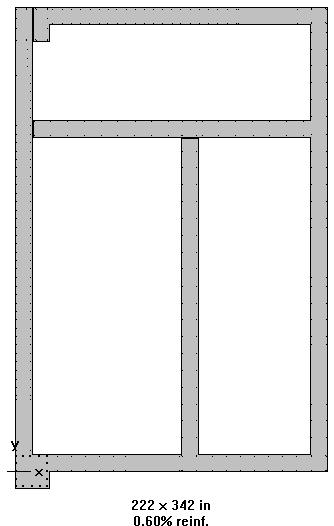
Interaction Diagram Dumbbell Concrete Shear Wall Unsymmetrical Boundary Elements
 Interaction Diagram Dumbbell Concrete Shear Wall Unsymmetrical Boundary Elements Interaction Diagram - Dumbbell Concrete Shear Wall Unsymmetrical Boundary Elements Investigate the capacity for the irregular
This Technical Note describes how the program checks column capacity or designs reinforced concrete columns when the ACI code is selected.
 COMPUTERS AND STRUCTURES, INC., BERKELEY, CALIFORNIA DECEMBER 2001 CONCRETE FRAME DESIGN ACI-318-99 Technical Note This Technical Note describes how the program checks column capacity or designs reinforced
Where and are the factored end moments of the column and >.
 11 LIMITATION OF THE SLENDERNESS RATIO----( ) 1-Nonsway (braced) frames: The ACI Code, Section 6.2.5 recommends the following limitations between short and long columns in braced (nonsway) frames: 1. The
ε t increases from the compressioncontrolled Figure 9.15: Adjusted interaction diagram
 CHAPTER NINE COLUMNS 4 b. The modified axial strength in compression is reduced to account for accidental eccentricity. The magnitude of axial force evaluated in step (a) is multiplied by 0.80 in case
Sway Column Example. PCA Notes on ACI 318
 Sway Column Example PCA Notes on ACI 318 ASDIP Concrete is available for purchase online at www.asdipsoft.com Example 11.2 Slenderness Effects for Columns in a Sway Frame Design columns C1 and C2 in the
Column Design. Columns Axial Load and Bending
 Column Design MORGAN STATE UNIVERSITY SCHOOL OF ARCHITECTURE AND PLANNING LECTURE VI Dr. Jason E. Charalambides = = Columns Axial Load and Bending We tend to have this image of columns that we envision
NOVEL FLOWCHART TO COMPUTE MOMENT MAGNIFICATION FOR LONG R/C COLUMNS
 NOVEL FLOWCHART TO COMPUTE MOMENT MAGNIFICATION FOR LONG R/C COLUMNS Abdul Kareem M. B. Al-Shammaa and Ehsan Ali Al-Zubaidi 2 Department of Urban Planning Faculty of Physical Planning University of Kufa
Supplement: Statically Indeterminate Frames
 : Statically Indeterminate Frames Approximate Analysis - In this supplement, we consider another approximate method of solving statically indeterminate frames subjected to lateral loads known as the. Like
Slenderness Effects for Concrete Columns in Sway Frame - Moment Magnification Method
 Slenderness Effets for Conrete Columns in Sway Frame - Moment Magnifiation Method Slender Conrete Column Design in Sway Frame Buildings Evaluate slenderness effet for olumns in a sway frame multistory
4.3 Moment Magnification
 CHAPTER 4: Reinforced Concrete Columns 4.3 Moment Magnification Description An ordinary or first order frame analysis does not include either the effects of the lateral sidesway deflections of the column
A q u a b l u e a t t h e G o l d e n M i l e
 A q u a b l u e a t t h e G o l d e n M i l e H a t o R e y, P u e r t o R i c o G e n e r a l B u i l d i n g I n f o r m a t i o n Building Facts: 7-story parking structure + luxury apartments 900,000
Slenderness Effects for Concrete Columns in Sway Frame - Moment Magnification Method
 Slenderness Effets for Conrete Columns in Sway Frame - Moment Magnifiation Method Slender Conrete Column Design in Sway Frame Buildings Evaluate slenderness effet for olumns in a sway frame multistory
Design of Reinforced Concrete Structures (II)
") Design of Reinforced Concrete Structures (II) Discussion Eng. Mohammed R. Kuheil Review The thickness of one-way ribbed slabs After finding the value of total load (Dead and live loads), the elements are
Design of Reinforced Concrete Structures (II) Discussion Eng. Mohammed R. Kuheil Review The thickness of one-way ribbed slabs After finding the value of total load (Dead and live loads), the elements are
Generation of Biaxial Interaction Surfaces
 COPUTERS AND STRUCTURES, INC., BERKELEY, CALIFORNIA AUGUST 2002 CONCRETE FRAE DESIGN BS 8110-97 Technical Note This Technical Note describes how the program checks column capacity or designs reinforced
Lecture-03 Design of Reinforced Concrete Members for Flexure and Axial Loads
 Lecture-03 Design of Reinforced Concrete Members for Flexure and Axial Loads By: Prof. Dr. Qaisar Ali Civil Engineering Department UET Peshawar drqaisarali@uetpeshawar.edu.pk www.drqaisarali.com Prof.
Designing Reinforced Concrete Rectangular Columns for Biaxial Bending
 ENGINEERING DATA REORT NUMBER 57 Designing Reinforced Concrete Rectangular Columns for Biaxial Bending A SERVICE OF THE CONCRETE REINFORCING STEEL INSTITUTE 933 N. lum Grove Rd., Schaumburg, Illinois 60173-4758
PUNCHING SHEAR CALCULATIONS 1 ACI 318; ADAPT-PT
 Structural Concrete Software System TN191_PT7_punching_shear_aci_4 011505 PUNCHING SHEAR CALCULATIONS 1 ACI 318; ADAPT-PT 1. OVERVIEW Punching shear calculation applies to column-supported slabs, classified
Design of Reinforced Concrete Beam for Shear
 Lecture 06 Design of Reinforced Concrete Beam for Shear By: Civil Engineering Department UET Peshawar drqaisarali@uetpeshawar.edu.pk Topics Addressed Shear Stresses in Rectangular Beams Diagonal Tension
MECHANICS OF MATERIALS Sample Problem 4.2
 Sample Problem 4. SOLUTON: Based on the cross section geometry, calculate the location of the section centroid and moment of inertia. ya ( + Y Ad ) A A cast-iron machine part is acted upon by a kn-m couple.
Direct Design Method and Design Diagram. For Reinforced Concrete Columns and Shear walls
 Direct Design Method and Design Diagram For Reinforced Concrete Columns and Shear walls BY MAJID HOUSHIAR B.S., Isfahan University of Technology, 1988 M.S., University of Illinois at Chicago, Chicago,
CHAPTER 14 BUCKLING ANALYSIS OF 1D AND 2D STRUCTURES
 CHAPTER 14 BUCKLING ANALYSIS OF 1D AND 2D STRUCTURES 14.1 GENERAL REMARKS In structures where dominant loading is usually static, the most common cause of the collapse is a buckling failure. Buckling may
Civil Engineering Design (1) Design of Reinforced Concrete Columns 2006/7
 Design of Reinforced Concrete Columns 2006/7") Civil Engineering Design (1) Design of Reinforced Concrete Columns 2006/7 Dr. Colin Caprani, Chartered Engineer 1 Contents 1. Introduction... 3 1.1 Background... 3 1.2 Failure Modes... 5 1.3 Design Aspects...
Civil Engineering Design (1) Design of Reinforced Concrete Columns 2006/7 Dr. Colin Caprani, Chartered Engineer 1 Contents 1. Introduction... 3 1.1 Background... 3 1.2 Failure Modes... 5 1.3 Design Aspects...
Development of Educational Software for the Design of Slender Reinforced Concrete Columns
 University of Colorado, Boulder CU Scholar Civil Engineering Graduate Theses & Dissertations Civil, Environmental, and Architectural Engineering Spring 1-1-2013 Development of Educational Software for
Reinforced concrete structures II. 4.5 Column Design
 4.5 Column Design A non-sway column AB of 300*450 cross-section resists at ultimate limit state, an axial load of 700 KN and end moment of 90 KNM and 0 KNM in the X direction,60 KNM and 27 KNM in the Y
999 TOWN & COUNTRY ROAD ORANGE, CALIFORNIA TITLE PUSHOVER ANALYSIS EXAMPLE BY R. MATTHEWS DATE 5/21/01
 DESCRIPTION Nonlinear static (pushover) analysis will be performed on a railroad bridge bent using several methods to determine its ultimate lateral deflection capability. 1. SAP2000 Nonlinear with axial-moment
A METHOD OF LOAD INCREMENTS FOR THE DETERMINATION OF SECOND-ORDER LIMIT LOAD AND COLLAPSE SAFETY OF REINFORCED CONCRETE FRAMED STRUCTURES
 A METHOD OF LOAD INCREMENTS FOR THE DETERMINATION OF SECOND-ORDER LIMIT LOAD AND COLLAPSE SAFETY OF REINFORCED CONCRETE FRAMED STRUCTURES Konuralp Girgin (Ph.D. Thesis, Institute of Science and Technology,
Lap splice length and details of column longitudinal reinforcement at plastic hinge region
 Lap length and details of column longitudinal reinforcement at plastic hinge region Hong-Gun Park 1) and Chul-Goo Kim 2) 1), 2 Department of Architecture and Architectural Engineering, Seoul National University,
Design of Reinforced Concrete Beam for Shear
 Lecture 06 Design of Reinforced Concrete Beam for Shear By: Prof Dr. Qaisar Ali Civil Engineering Department UET Peshawar drqaisarali@uetpeshawar.edu.pk 1 Topics Addressed Shear Stresses in Rectangular
8.1 Internal Forces in Structural Members
 8.1 Internal Forces in Structural Members 8.1 Internal Forces in Structural Members xample 1, page 1 of 4 1. etermine the normal force, shear force, and moment at sections passing through a) and b). 4
Serviceability Deflection calculation
 Chp-6:Lecture Goals Serviceability Deflection calculation Deflection example Structural Design Profession is concerned with: Limit States Philosophy: Strength Limit State (safety-fracture, fatigue, overturning
Pre-stressed concrete = Pre-compression concrete Pre-compression stresses is applied at the place when tensile stress occur Concrete weak in tension
 Pre-stressed concrete = Pre-compression concrete Pre-compression stresses is applied at the place when tensile stress occur Concrete weak in tension but strong in compression Steel tendon is first stressed
Example 4.1 [Uni-axial Column Design] Solution. Step 1- Material Step 2-Determine the normalized axial and bending moment value
![Example 4.1 [Uni-axial Column Design] Solution. Step 1- Material Step 2-Determine the normalized axial and bending moment value](/thumbs/75/72436916.jpg "Example 4.1 [Uni-axial Column Design] Solution. Step 1- Material Step 2-Determine the normalized axial and bending moment value") Example 4.1 [Uni-axial Column Design] 1. Design the braced short column to sustain a design load of 1100 KN and a design moment of 160KNm which include all other effects.use C5/30 and S460 class 1 works
Example 4.1 [Uni-axial Column Design] 1. Design the braced short column to sustain a design load of 1100 KN and a design moment of 160KNm which include all other effects.use C5/30 and S460 class 1 works
Chapter 8. Shear and Diagonal Tension
 Chapter 8. and Diagonal Tension 8.1. READING ASSIGNMENT Text Chapter 4; Sections 4.1-4.5 Code Chapter 11; Sections 11.1.1, 11.3, 11.5.1, 11.5.3, 11.5.4, 11.5.5.1, and 11.5.6 8.2. INTRODUCTION OF SHEAR
Entrance exam Master Course
 - 1 - Guidelines for completion of test: On each page, fill in your name and your application code Each question has four answers while only one answer is correct. o Marked correct answer means 4 points
Tutorial #1 - CivE. 205 Name: I.D:
 Tutorial # - CivE. 0 Name: I.D: Eercise : For the Beam below: - Calculate the reactions at the supports and check the equilibrium of point a - Define the points at which there is change in load or beam
twenty one concrete construction: shear & deflection ARCHITECTURAL STRUCTURES: FORM, BEHAVIOR, AND DESIGN DR. ANNE NICHOLS SUMMER 2014 lecture
 ARCHITECTURAL STRUCTURES: FORM, BEHAVIOR, AND DESIGN DR. ANNE NICHOLS SUMMER 2014 lecture twenty one concrete construction: Copyright Kirk Martini shear & deflection Concrete Shear 1 Shear in Concrete
Sabah Shawkat Cabinet of Structural Engineering Walls carrying vertical loads should be designed as columns. Basically walls are designed in
 Sabah Shawkat Cabinet of Structural Engineering 17 3.6 Shear walls Walls carrying vertical loads should be designed as columns. Basically walls are designed in the same manner as columns, but there are
Supplement: Statically Indeterminate Trusses and Frames
 : Statically Indeterminate Trusses and Frames Approximate Analysis - In this supplement, we consider an approximate method of solving statically indeterminate trusses and frames subjected to lateral loads
CHAPTER 4: BENDING OF BEAMS
 (74) CHAPTER 4: BENDING OF BEAMS This chapter will be devoted to the analysis of prismatic members subjected to equal and opposite couples M and M' acting in the same longitudinal plane. Such members are
Finite Element Modelling with Plastic Hinges
 01/02/2016 Marco Donà Finite Element Modelling with Plastic Hinges 1 Plastic hinge approach A plastic hinge represents a concentrated post-yield behaviour in one or more degrees of freedom. Hinges only
Lecture-08 Gravity Load Analysis of RC Structures
 Lecture-08 Gravity Load Analysis of RC Structures By: Prof Dr. Qaisar Ali Civil Engineering Department UET Peshawar www.drqaisarali.com 1 Contents Analysis Approaches Point of Inflection Method Equivalent
Support Reactions: a + M C = 0; 800(10) F DE(4) F DE(2) = 0. F DE = 2000 lb. + c F y = 0; (2000) - C y = 0 C y = 400 lb
 F DE(4) F DE(2) = 0. F DE = 2000 lb. + c F y = 0; (2000) - C y = 0 C y = 400 lb") 06 Solutions 46060_Part1 5/27/10 3:51 P Page 334 6 11. The overhanging beam has been fabricated with a projected arm D on it. Draw the shear and moment diagrams for the beam C if it supports a load of
06 Solutions 46060_Part1 5/27/10 3:51 P Page 334 6 11. The overhanging beam has been fabricated with a projected arm D on it. Draw the shear and moment diagrams for the beam C if it supports a load of
CHAPTER 4. ANALYSIS AND DESIGN OF COLUMNS
 4.1. INTRODUCTION CHAPTER 4. ANALYSIS AND DESIGN OF COLUMNS A column is a vertical structural member transmitting axial compression loads with or without moments. The cross sectional dimensions of a column
Ch. 10 Design of Short Columns Subject to Axial Load and Bending
 Ch. 10 Design o Short Columns Subjet to Axial Load and Bending Axial Loading and Bending Development o Interation Diagram Column Design Using P-M Interation Diagram Shear in Columns Biaxial Bending Examples
Purpose of this Guide: To thoroughly prepare students for the exact types of problems that will be on Exam 3.
 ES230 STRENGTH OF MTERILS Exam 3 Study Guide Exam 3: Wednesday, March 8 th in-class Updated 3/3/17 Purpose of this Guide: To thoroughly prepare students for the exact types of problems that will be on
3.5 Reinforced Concrete Section Properties
 CHAPER 3: Reinforced Concrete Slabs and Beams 3.5 Reinforced Concrete Section Properties Description his application calculates gross section moment of inertia neglecting reinforcement, moment of inertia
Lecture-04 Design of RC Members for Shear and Torsion
 Lecture-04 Design of RC Members for Shear and Torsion By: Prof. Dr. Qaisar Ali Civil Engineering Department UET Peshawar drqaisarali@uetpeshawar.edu.pk www.drqaisarali.com 1 Topics Addressed Design of
DNV DESIGN. POU_Rect - Design Report Page 1 of 11
 DNV DESIGN Page 1 of 11 Details Code Details Code DNV 2.7-1 2006 with AISC 360-10 ASD Description This is the 2006 edition of the DNV Standard for Certification No 2.7-1, which defines minimum technical
UC Berkeley CE 123 Fall 2017 Instructor: Alan Kren
 CE 123 - Reinforced Concrete Midterm Examination No. 2 Instructions: Read these instructions. Do not turn the exam over until instructed to do so. Work all problems. Pace yourself so that you have time
SPECIFIC VERIFICATION Chapter 5
 As = 736624/(0.5*413.69) = 3562 mm 2 (ADAPT 3569 mm 2, B29, C6) Data Block 27 - Compressive Stresses The initial compressive strength, f ci, is the strength entered in the Material/Concrete input screen.
AXIAL COLLAPSE OF REINFORCED CONCRETE COLUMNS
 3 th World Conference on Earthquake Engineering Vancouver, B.C., Canada August -6, 4 Paper No. 699 AXIAL COLLAPSE OF REINFORCED CONCRETE COLUMNS Manabu YOSHIMURA, Yoshikazu TAKAINE and Takaya NAKAMURA
Chapter (6) Geometric Design of Shallow Foundations
 Geometric Design of Shallow Foundations") Chapter (6) Geometric Design of Shallow Foundations Introduction As we stated in Chapter 3, foundations are considered to be shallow if if [D (3 4)B]. Shallow foundations have several advantages: minimum
Chapter (6) Geometric Design of Shallow Foundations Introduction As we stated in Chapter 3, foundations are considered to be shallow if if [D (3 4)B]. Shallow foundations have several advantages: minimum
Design of a Multi-Storied RC Building
 Design of a Multi-Storied RC Building 16 14 14 3 C 1 B 1 C 2 B 2 C 3 B 3 C 4 13 B 15 (S 1 ) B 16 (S 2 ) B 17 (S 3 ) B 18 7 B 4 B 5 B 6 B 7 C 5 C 6 C 7 C 8 C 9 7 B 20 B 22 14 B 19 (S 4 ) C 10 C 11 B 23
Application nr. 7 (Connections) Strength of bolted connections to EN (Eurocode 3, Part 1.8)
 Strength of bolted connections to EN (Eurocode 3, Part 1.8)") Application nr. 7 (Connections) Strength of bolted connections to EN 1993-1-8 (Eurocode 3, Part 1.8) PART 1: Bolted shear connection (Category A bearing type, to EN1993-1-8) Structural element Tension
Application nr. 7 (Connections) Strength of bolted connections to EN 1993-1-8 (Eurocode 3, Part 1.8) PART 1: Bolted shear connection (Category A bearing type, to EN1993-1-8) Structural element Tension
EARTHQUAKE ANALYSIS with SAP2000
 EARTHQUAKE ANALYSIS with SAP2000 Prepared by Bob Matthews 2004 Robert Matthews Page 1 EARTHQUAKE ANALYSIS EXAMPLE The earthquake analysis capabilities of SAP2000 are demonstrated using a railroad bridge
CHAPTER 6: ULTIMATE LIMIT STATE
 CHAPTER 6: ULTIMATE LIMIT STATE 6.1 GENERAL It shall be in accordance with JSCE Standard Specification (Design), 6.1. The collapse mechanism in statically indeterminate structures shall not be considered.
Lecture-09 Introduction to Earthquake Resistant Analysis & Design of RC Structures (Part I)
") Lecture-09 Introduction to Earthquake Resistant Analysis & Design of RC Structures (Part I) By: Prof Dr. Qaisar Ali Civil Engineering Department UET Peshawar www.drqaisarali.com 1 Topics Introduction Earthquake
Lecture-09 Introduction to Earthquake Resistant Analysis & Design of RC Structures (Part I) By: Prof Dr. Qaisar Ali Civil Engineering Department UET Peshawar www.drqaisarali.com 1 Topics Introduction Earthquake
DESIGN OF BEAM-COLUMNS - II
 DESIGN OF BEA-COLUNS-II 14 DESIGN OF BEA-COLUNS - II 1.0 INTRODUCTION Beam-columns are members subjected to combined bending and axial compression. Their behaviour under uniaxial bending, biaxial bending
PEER/SSC Tall Building Design. Case study #2
 PEER/SSC Tall Building Design Case study #2 Typical Plan View at Ground Floor and Below Typical Plan View at 2 nd Floor and Above Code Design Code Design Shear Wall properties Shear wall thickness and
Module 10. Compression Members. Version 2 CE IIT, Kharagpur
 Module 10 Compression Members Lesson 27 Slender Columns Instructional Objectives: At the end of this lesson, the student should be able to: define a slender column, give three reasons for its increasing
Biaxial Analysis of General Shaped Base Plates
 Biaxial Analysis of General Shaped Base Plates R. GONZALO ORELLANA 1 Summary: A linear model is used for the contact stresses calculation between a steel base plate and a concrete foundation. It is also
2010 NASCC / Structures Congress Orlando, Florida May 13, 2010
 2010 NASCC / Structures Congress Orlando, Florida May 13, 2010 Load Transfer in Composite Construction (Chapter I of the 2010 AISC Specification) William P. Jacobs, V Stanley D. Lindsey & Associates Atlanta,
Lecture 15 Strain and stress in beams
 Spring, 2019 ME 323 Mechanics of Materials Lecture 15 Strain and stress in beams Reading assignment: 6.1 6.2 News: Instructor: Prof. Marcial Gonzalez Last modified: 1/6/19 9:42:38 PM Beam theory (@ ME
TORSION INCLUDING WARPING OF OPEN SECTIONS (I, C, Z, T AND L SHAPES)
") Page1 TORSION INCLUDING WARPING OF OPEN SECTIONS (I, C, Z, T AND L SHAPES) Restrained warping for the torsion of thin-wall open sections is not included in most commonly used frame analysis programs. Almost
Page1 TORSION INCLUDING WARPING OF OPEN SECTIONS (I, C, Z, T AND L SHAPES) Restrained warping for the torsion of thin-wall open sections is not included in most commonly used frame analysis programs. Almost
Details of Check for Boundary Element Requirements
 COMUTERS AND STRUCTURES, INC., BERKELEY, CALIFORNIA DECEMBER 2001 SHEAR WALL DESIGN UCB 97 Technical te Wall ier Bondary Elements This Technical te describes how the program considers the bondary element
7.3 Design of members subjected to combined forces
 7.3 Design of members subjected to combined forces 7.3.1 General In the previous chapters of Draft IS: 800 LSM version, we have stipulated the codal provisions for determining the stress distribution in
Determine the resultant internal loadings acting on the cross section at C of the beam shown in Fig. 1 4a.
 E X M P L E 1.1 Determine the resultant internal loadings acting on the cross section at of the beam shown in Fig. 1 a. 70 N/m m 6 m Fig. 1 Support Reactions. This problem can be solved in the most direct
T4/1 Analysis of a barrel vault simplified calculation
 T4. MASONRY STRUCTURES 1/4 T4/1 Analysis of a barrel vault simplified calculation Exercise: Check the given masonry vault for symmetrical loading! ata: q k = 4 kn/m (live load) ρ masonry = 17 kn/m 3 (specific
ENG202 Statics Lecture 16, Section 7.1
 ENG202 Statics Lecture 16, Section 7.1 Internal Forces Developed in Structural Members - Design of any structural member requires an investigation of the loading acting within the member in order to be
Multi Linear Elastic and Plastic Link in SAP2000
 26/01/2016 Marco Donà Multi Linear Elastic and Plastic Link in SAP2000 1 General principles Link object connects two joints, i and j, separated by length L, such that specialized structural behaviour may
Chapter. Materials. 1.1 Notations Used in This Chapter
 Chapter 1 Materials 1.1 Notations Used in This Chapter A Area of concrete cross-section C s Constant depending on the type of curing C t Creep coefficient (C t = ε sp /ε i ) C u Ultimate creep coefficient
Stress Analysis Lecture 4 ME 276 Spring Dr./ Ahmed Mohamed Nagib Elmekawy
 Stress Analysis Lecture 4 ME 76 Spring 017-018 Dr./ Ahmed Mohamed Nagib Elmekawy Shear and Moment Diagrams Beam Sign Convention The positive directions are as follows: The internal shear force causes a
LIMITATIONS OF THE STANDARD INTERACTION FORMULA FOR BIAXIAL BENDING AS APPLIED TO RECTANGULAR STEEL TUBULAR COLUMNS
 LIMITATIONS OF THE STANDARD INTERACTION FORMULA FOR BIAXIAL BENDING AS APPLIED TO RECTANGULAR STEEL TUBULAR COLUMNS Ramon V. Jarquio 1 ABSTRACT The limitations of the standard interaction formula for biaxial
Problem d d d B C E D. 0.8d. Additional lecturebook examples 29 ME 323
 Problem 9.1 Two beam segments, AC and CD, are connected together at C by a frictionless pin. Segment CD is cantilevered from a rigid support at D, and segment AC has a roller support at A. a) Determine
Advanced Structural Analysis EGF Section Properties and Bending
 Advanced Structural Analysis EGF316 3. Section Properties and Bending 3.1 Loads in beams When we analyse beams, we need to consider various types of loads acting on them, for example, axial forces, shear
CIVIL DEPARTMENT MECHANICS OF STRUCTURES- ASSIGNMENT NO 1. Brach: CE YEAR:
 MECHANICS OF STRUCTURES- ASSIGNMENT NO 1 SEMESTER: V 1) Find the least moment of Inertia about the centroidal axes X-X and Y-Y of an unequal angle section 125 mm 75 mm 10 mm as shown in figure 2) Determine
Problem 7.1 Determine the soil pressure distribution under the footing. Elevation. Plan. M 180 e 1.5 ft P 120. (a) B= L= 8 ft L e 1.5 ft 1.
 B= L= 8 ft L e 1.5 ft 1.") Problem 7.1 Determine the soil pressure distribution under the footing. Elevation Plan M 180 e 1.5 ft P 10 (a) B= L= 8 ft L e 1.5 ft 1.33 ft 6 1 q q P 6 (P e) 180 6 (180) 4.9 kip/ft B L B L 8(8) 8 3 P
Problem 7.1 Determine the soil pressure distribution under the footing. Elevation Plan M 180 e 1.5 ft P 10 (a) B= L= 8 ft L e 1.5 ft 1.33 ft 6 1 q q P 6 (P e) 180 6 (180) 4.9 kip/ft B L B L 8(8) 8 3 P
NUMERICAL SIMULATIONS OF CORNERS IN RC FRAMES USING STRUT-AND-TIE METHOD AND CDP MODEL
 Numerical simulations of corners in RC frames using Strut-and-Tie Method and CDP model XIII International Conference on Computational Plasticity. Fundamentals and Applications COMPLAS XIII E. Oñate, D.R.J.
Chapter Objectives. Design a beam to resist both bendingand shear loads
 Chapter Objectives Design a beam to resist both bendingand shear loads A Bridge Deck under Bending Action Castellated Beams Post-tensioned Concrete Beam Lateral Distortion of a Beam Due to Lateral Load
Comparison of Structural Models for Seismic Analysis of Multi-Storey Frame Buildings
 Comparison of Structural Models for Seismic Analysis of Multi-Storey Frame Buildings Dj. Ladjinovic, A. Raseta, A. Radujkovic & R. Folic University of Novi Sad, Faculty of Technical Sciences, Novi Sad,
ACI Fall Convention 2010 Pittsburgh, PA ARGENTINA DOCUMENT
 ACI Fall Convention 2010 Pittsburgh, PA October 24-28, 2010 ARGENTINA DOCUMENT Developed for INTI-CIRSOC by Eng. Daniel Ortega from INTI-CIRSOC Eng. Victorio Hernández Balat from Quasdam Ingeniería COMMENTARIES
Assignment 1 - actions
 Assignment 1 - actions b = 1,5 m a = 1 q kn/m 2 Determine action on the beam for verification of the ultimate limit state. Axial distance of the beams is 1 to 2 m, cross section dimensions 0,45 0,20 m
REINFORCED CONCRETE DESIGN 1. Design of Column (Examples and Tutorials)
") For updated version, please click on http://ocw.ump.edu.my REINFORCED CONCRETE DESIGN 1 Design of Column (Examples and Tutorials) by Dr. Sharifah Maszura Syed Mohsin Faculty of Civil Engineering and Earth
For updated version, please click on http://ocw.ump.edu.my REINFORCED CONCRETE DESIGN 1 Design of Column (Examples and Tutorials) by Dr. Sharifah Maszura Syed Mohsin Faculty of Civil Engineering and Earth
Failure from static loading
 Failure from static loading Topics Quiz /1/07 Failures from static loading Reading Chapter 5 Homework HW 3 due /1 HW 4 due /8 What is Failure? Failure any change in a machine part which makes it unable
9.5 Compression Members
 9.5 Compression Members This section covers the following topics. Introduction Analysis Development of Interaction Diagram Effect of Prestressing Force 9.5.1 Introduction Prestressing is meaningful when
UNIVERSITY OF BOLTON SCHOOL OF ENGINEERING. BEng (HONS) CIVIL ENGINEERING SEMESTER 1 EXAMINATION 2016/2017 MATHEMATICS & STRUCTURAL ANALYSIS
 CIVIL ENGINEERING SEMESTER 1 EXAMINATION 2016/2017 MATHEMATICS & STRUCTURAL ANALYSIS") TW21 UNIVERSITY OF BOLTON SCHOOL OF ENGINEERING BEng (HONS) CIVIL ENGINEERING SEMESTER 1 EXAMINATION 2016/2017 MATHEMATICS & STRUCTURAL ANALYSIS MODULE NO: CIE4011 Date: Wednesday 11 th January 2017 Time:
TW21 UNIVERSITY OF BOLTON SCHOOL OF ENGINEERING BEng (HONS) CIVIL ENGINEERING SEMESTER 1 EXAMINATION 2016/2017 MATHEMATICS & STRUCTURAL ANALYSIS MODULE NO: CIE4011 Date: Wednesday 11 th January 2017 Time:
Appendix K Design Examples
 Appendix K Design Examples Example 1 * Two-Span I-Girder Bridge Continuous for Live Loads AASHTO Type IV I girder Zero Skew (a) Bridge Deck The bridge deck reinforcement using A615 rebars is shown below.
and F NAME: ME rd Sample Final Exam PROBLEM 1 (25 points) Prob. 1 questions are all or nothing. PROBLEM 1A. (5 points)
 Prob. 1 questions are all or nothing. PROBLEM 1A. (5 points)") ME 270 3 rd Sample inal Exam PROBLEM 1 (25 points) Prob. 1 questions are all or nothing. PROBLEM 1A. (5 points) IND: In your own words, please state Newton s Laws: 1 st Law = 2 nd Law = 3 rd Law = PROBLEM
ME 270 3 rd Sample inal Exam PROBLEM 1 (25 points) Prob. 1 questions are all or nothing. PROBLEM 1A. (5 points) IND: In your own words, please state Newton s Laws: 1 st Law = 2 nd Law = 3 rd Law = PROBLEM
Flexure: Behavior and Nominal Strength of Beam Sections
 4 5000 4000 (increased d ) (increased f (increased A s or f y ) c or b) Flexure: Behavior and Nominal Strength of Beam Sections Moment (kip-in.) 3000 2000 1000 0 0 (basic) (A s 0.5A s ) 0.0005 0.001 0.0015
CHAPTER 2 Failure/Fracture Criterion
 (11) CHAPTER 2 Failure/Fracture Criterion (12) Failure (Yield) Criteria for Ductile Materials under Plane Stress Designer engineer: 1- Analysis of loading (for simple geometry using what you learn here
A Simply supported beam with a concentrated load at mid-span: Loading Stages
 A Simply supported beam with a concentrated load at mid-span: Loading Stages P L/2 L PL/4 MOMNT F b < 1 lastic F b = 2 lastic F b = 3 lastoplastic 4 F b = Plastic hinge Plastic Dr. M.. Haque, P.. (LRFD:
Basic Energy Principles in Stiffness Analysis
 Basic Energy Principles in Stiffness Analysis Stress-Strain Relations The application of any theory requires knowledge of the physical properties of the material(s) comprising the structure. We are limiting
Portal Frame Calculations Lateral Loads
 Portal Frame Calculations Lateral Loads Consider the following multi-story frame: The portal method makes several assumptions about the internal forces of the columns and beams in a rigid frame: 1) Inflection
Strain Gage Calibration Factors for Constant Room Temperature Conditions. Gage Resistance, Gage Factor and Transverse Sensitivity Coefficient)
") Strain Gage Calibration Factors for Constant Room Temperature Conditions (Or equivalently, measurement of the room temperature (Or equivalently, measurement of the room temperature Gage Resistance, Gage
Strain Gage Calibration Factors for Constant Room Temperature Conditions (Or equivalently, measurement of the room temperature (Or equivalently, measurement of the room temperature Gage Resistance, Gage
 mportant nstructions to examiners: ) The answers should be examined by key words and not as word-to-word as given in the model answer scheme. ) The model answer and the answer written by candidate may
Railroad Concrete Tie Failure Analysis
 Railroad Concrete Tie Failure Analysis Hailing Yu, David Jeong, Brian Marquis, and Michael Coltman 2014 International Crosstie & Fastening System Symposium June 3-5, 2014 The National Transportation Systems
CHAPTER 5. T a = 0.03 (180) 0.75 = 1.47 sec 5.12 Steel moment frame. h n = = 260 ft. T a = (260) 0.80 = 2.39 sec. Question No.
 0.75 = 1.47 sec 5.12 Steel moment frame. h n = = 260 ft. T a = (260) 0.80 = 2.39 sec. Question No.") CHAPTER 5 Question Brief Explanation No. 5.1 From Fig. IBC 1613.5(3) and (4) enlarged region 1 (ASCE 7 Fig. -3 and -4) S S = 1.5g, and S 1 = 0.6g. The g term is already factored in the equations, thus
CHAPTER 5 Question Brief Explanation No. 5.1 From Fig. IBC 1613.5(3) and (4) enlarged region 1 (ASCE 7 Fig. -3 and -4) S S = 1.5g, and S 1 = 0.6g. The g term is already factored in the equations, thus
CHAPTER 4. Design of R C Beams
 CHAPTER 4 Design of R C Beams Learning Objectives Identify the data, formulae and procedures for design of R C beams Design simply-supported and continuous R C beams by integrating the following processes
Failure in Flexure. Introduction to Steel Design, Tensile Steel Members Modes of Failure & Effective Areas
 Introduction to Steel Design, Tensile Steel Members Modes of Failure & Effective Areas MORGAN STATE UNIVERSITY SCHOOL OF ARCHITECTURE AND PLANNING LECTURE VIII Dr. Jason E. Charalambides Failure in Flexure!