Improving the earthquake performance of bridges using seismic isolation
|
|
|
- Leo Hudson
- 5 years ago
- Views:
Transcription
1 Improving the earthquake performance of bridges using seismic isolation Ian Buckle Professor, University of Nevada Reno TRB Webinar February 10, 2016 Sponsored by TRB Committee AFF50: Seismic Design and Performance of Bridges
2 Many colleagues in: Academia DOT practitioners Industry Acknowledgements AASHTO SCOBS Committees T-2 (Bearings) and T-3 (Seismic Design) NCHRP 20-7 (262) Review and Update of the AASHTO Guide Specifications for Seismic Isolation Design
3 Outline Conventional vs seismic isolation design History Basic requirements (principles) Examples (applications) Limitations Design of a bridge isolation system Additional sources of information Design examples Q&A
4 Outline Conventional vs seismic isolation design History Basic requirements (principles) Examples (applications) Limitations Design of a bridge isolation system Additional sources of information Design examples Q&A
5 Conventional seismic design Fundamental requirement of seismic design: Capacity Demand > 1.0
6 Demand But demand is excessive F smax ~ 1.1W
7 Demand Because demand is excessive it is often impractical to provided sufficient capacity to keep structure elastic Hence damage is accepted in form of plastic deformation and concrete spalling in hinge zones capacity seismic design
8 Conventional seismic design Since yield is permitted: Deformation Capacity Deformation Demand INCREASE CAPACITY > 1.0


9 Conventional seismic design Deconstruction of Christchurch,

10 Conventional seismic design
11 Alternative approach Deformation Capacity Deformation Demand > 1.0 REDUCE DEMAND

12 Alternative approach
13 Alternative approach Easiest way to reduce demand is to increase flexibility and Fsmax 1.1W lengthen period, T Fsmax 0.25W T = 0.5 sec T=1.5 sec
14 Alternative approach This approach is essence of seismic isolation add flexibility to lengthen period to give a better ride
15 Seismic isolation By lengthening period, substantial reductions in forces (e.g. base shear) are possible and often feasible to keep structure elastic during design earthquake (i.e. no yield) Significant reductions in repair costs Continuing functionality is achievable Applicable to new and existing structures Applicable to buildings, bridges, industrial plant
16 But Increasing the period increases displacement Dmax 4.9 in Dmax 2.7 in T=0.5 sec T=1.5 sec
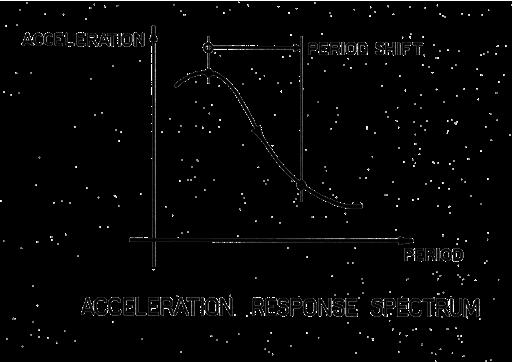
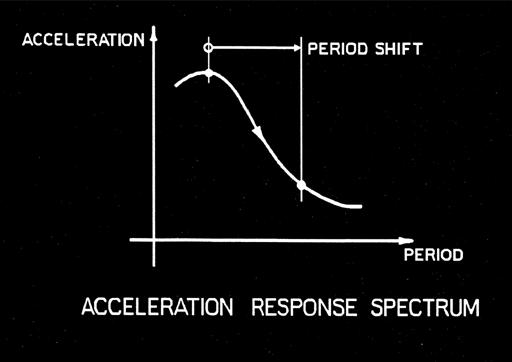
17 Force-displacement tradeoff Spectral acceleration, Period shift Increased damping Spectral displacement, Period, T Increased damping T 1 T 2 Period, T
18 Force-displacement tradeoff Tradeoff between force and displacement is one of the challenging aspects of base isolation Additional damping is usually added to limit the increase in displacements Note that these larger displacements occur mainly in isolator themselves and not in the structure (i.e. columns). Even though the system displacements may be large, column drift is small
19 Outline Conventional vs seismic isolation design History Basic requirements (principles) Examples (applications) Limitations Design of a bridge isolation system Additional sources of information Design examples Q&A


20 History The Distant Past


21 History So. Rangitikei River Bridge, 1979 World s First Base-Isolated Bridge


22 History William Clayton Building, 1981 World s First Base- Isolated Building
23 History - Today Today seismic isolation is but one member of a growing family of earthquake protective systems that includes: Mechanical energy dissipators Tuned mass dampers Active mass dampers Adaptive control systems Semi-active isolation
24 History - Today EARTHQUAKE PROTECTION SYSTEMS PASSIVE PROTECTIVE SYSTEMS HYBRID PROTECTIVE SYSTEMS ACTIVE PROTECTIVE SYSTEMS Tuned mass damper Active isolation Active mass damper Energy dissipation Semi-active isolation Active braces Seismic isolation Semi-active mass damper Adaptive control
25 Outline Conventional vs seismic isolation design History Basic requirements (principles) Examples (applications) Limitations Design of a bridge isolation system Additional sources of information Design examples Q&A
26 Basic requirements of isolation system 1) Flexible mount to lengthen period of the structural system 2) Damper (energy dissipator) to limit the displacement in the flexible mount 3) Restraint for service loads (wind, braking ) 4) Restoring device to re-centre system following an earthquake Above requirement- stiff for service loads, flexible for earthquake loads - means that all practical isolation systems are nonlinear.
 = maximum isolator displacement EDC = area of hysteretic loop = energy dissipated per")
27 Basic requirements Q d = characteristic strength F y = yield strength F max = maximum isolator force K d = post-elastic stiffness K u = loading and unloading stiffness K eff = effective stiffness max (= u max ) = maximum isolator displacement EDC = area of hysteretic loop = energy dissipated per cycle.
28 Basic properties Two most important properties are: Q d : characteristic strength, pseudo yield K d : second slope, isolator stiffness after yield Q d and K d determine effective stiffness (K eff ) and energy dissipated per cycle (EDC) for given displacement, max K eff determines effective period T eff and EDC determines equivalent viscous damping ratio, h eff
29 Basic requirements of isolation system 1) Flexible mount to lengthen period of combined structure-isolator system 2) Damper (energy dissipator) to control displacement in flexible mount 3) Restraint for service loads (wind, braking ) 4) Restoring device to re-centre system following earthquake
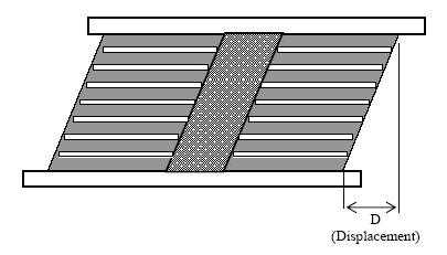
30 Basic requirements Requirement Flexible mount Damper Restraint Restoring device Examples Elastomeric bearing (natural or synthetic rubber) Flat or curved sliding surface PTFE and stainless steel) Plastic deformation (steel, lead ) Friction Viscosity of fluid High damping rubber compound Mechanical fuse Elastic stiffness of a yielding dissipator Friction (pre-slip) Elastomeric or metal spring Concave sliding surface
31 Basic hardware Isolator Type Elastomeric systems Sliding Systems Available devices Lead-rubber bearing (LRB) -standard natural rubber bearing with lead core High damping rubber bearing (HDR) -modified natural rubber bearing with high damping rubber compound Concave friction bearing (CFB) -concave slider using PTFE and stainless steel Flat plate friction bearing (FPB) -flat plate slider using PTFE and stainless steel, and elastomeric springs


32 Basic hardware Left: Lead rubber bearing (LRB) Right: Concave friction bearing (CFB)
33 Flat plate friction bearing (FPB) Basic hardware
34 Outline Conventional vs seismic isolation design History Basic requirements (principles) Examples (applications) Limitations Design of a bridge isolation system Additional sources of information Design examples Q&A

35 Applications: US 101 Sierra Point, CA

36 Applications: I-680 Benicia-Martinez, CA

37 Applications: JFK Airport Light Rail, NY


38 Applications: Bolu Viaduct, Turkey
39 Applications in U.S., Canada, Mexico State Number of isolated bridges Percent of total number of isolated bridges in North America California 28 13% New Jersey 23 11% New York 22 11% Massachusetts 20 10% New Hampshire 14 7% Illinois 14 7% Total 121
40 Applications in U.S., Canada, Mexico Isolator Type Applications (Percent of total number of isolated bridges in North America) Lead-rubber bearing 75% Flat plate friction bearing 20% Other: Concave friction bearing, High damping rubber bearing, Natural rubber bearing 5%
41 Outline Conventional vs seismic isolation design History Basic requirements (principles) Examples (applications) Limitations Design of a bridge isolation system Additional sources of information Design examples Q&A
42 Limitations Successful application of isolation is dependent on the shape of the acceleration response spectrum Sites not suitable for isolation include those where the spectrum does not decay rapidly with increasing period, such as a soft soil site
43 Limitations Rock spectrum Soft soil spectrum
44 Limitations Other sites where isolation is questionable include near-field sites where long period, highvelocity pulses may be encountered Bridges where isolation is questionable include those: with tall piers that have long fixed-base periods in high seismic zones on soft sites where superstructure displacements are large and movement joints expensive Exceptions exist
45 Conversely Bridges most suitable for isolation include those with relatively short fixed-base periods (< 1.5 s) on competent soils, and not in near-field.
46 Outline Conventional vs seismic isolation design History Basic requirements (principles) Examples (applications) Limitations Design of a bridge isolation system Additional sources of information Design examples Q&A
47 Design of a bridge Isolation system Three step process: 1. Select required performance criteria 2. Determine properties of the isolation system to achieve required performance (e.g. Q d and K d ) using one or more methods of analysis 3. Select isolator type and design V K d Q d hardware to achieve required system properties D (i.e. Q d and K d values) using a rational design procedure
48 Performance criteria Usually set by owner Examples include: o Not-to-exceed total base shear for Design Earthquake (1,000 yr return period) o Elastic columns during Design Earthquake (1,000 yr) o Not-to-exceed longitudinal displacement in superstructure during Design Earthquake o Essentially elastic behavior for the Maximum Considered Earthquake (MCE, 2,500 yr) o Reparable damage in MCE, but not collapse
49 Analysis methods for isolated bridges Bridges with nonlinear isolators may be analyzed using linear methods provided equivalent properties are used, such as effective stiffness, and equivalent viscous damping, based on the hysteretic energy dissipated by the isolators.
50 Analysis methods for isolated bridges Uniform Load Method Single Mode Spectral Method Multimode Spectral Method Time History Method
51 Analysis methods Uniform Load Simplified Method Single Mode Spectral Method Multimode Spectral Method Time History Method
52 Assumptions in Simplified Method 1. Superstructure acts a rigid-diaphragm compared to flexibility of isolators 2. Single displacement describes motion of superstructure, i.e. single degree-of-freedom system 3. Nonlinear properties of isolators may be represented by bilinear loops 4. Bilinear stiffness can be V represented by K isol, effective stiffness. Note K isol is dependent on displacement, D K isol D
53 Assumptions in Simplified Method 5. Hysteretic energy dissipation may be represented by viscous damping, i.e., work done during plastic deformation can be represented by work done moving viscous fluid through an orifice. Equivalent viscous damping ratio given by 2 Q h = π F d m D (1 D 6. Acceleration spectrum is inversely proportional to period (i.e. S A = a / T) y isol )
54 AASHTO Design Response Spectra S A (A) S D1 S D1 / B L S D (D) Spectral Acceleration (g) 5 % damping h % damping 1.0s Period, T Spectral Displacement 5 % damping AASHTO Spectra (S A ) are for 5% damping on a rock site (Site Class B) For sites other than rock, the spectra are modified by Site Factors, F a and F v For damping other than 5%, the spectra are modified by a Damping Factor, B L Fv S SD 1 S A A = 1 = B T B T L L 10S D1 10S D1 / B L 1.0s h % damping Period, T 2 g Fv S1T SD 1 SD D = = π BL BL T
55 Assumptions in Simplified Method 7. Acceleration spectra for 5% viscous damping may be scaled for actual damping (h) by dividing by a damping coefficient, B L B L = h B L is used in long-period range of spectrum. Another factor (B S ) is used in short-period range. Isolated bridges usually fall in long-period range.
56 Simplified Method Basic steps: 1. Assume value for D isol 2. Calculate effective stiffness, K isol K d Q d V F m 3. Calculate max. force, F m 4. Calculate effective period, T eff K isol D D isol Q = K isol isol d K isol + Disol d F = K m D T eff = 2π W gk isol
57 Simplified Method continued 5. Calculate viscous damping ratio, h 6. Calculate damping coefficient, B L 7. Calculate D isol 8. Compare with value for D isol in Step (1). Repeat until convergence. V Q d K d K isol D y g F S v 1 Disol = 2 4π BL T D D isol eff F m h 2 Q D d y = (1 ) h 0. 3 B ( ) π F D L = 0.05 m isol D isol = 9.79 Fv S1 Teff ( inches) B L
58 Example 1: Simplified Method The superstructure of a 2-span bridge weighs 533 K. It is located on a rock site where S D1 = The bridge is seismically isolated with 12 isolation bearings at the piers and abutments. Isolation system
59 Example 1(a) (a) If Q d = 0.075W and K d = 13.0 K/in (summed over all the isolators), calculate the maximum displacement of the superstructure and the total base shear. Neglect pier flexibility.
60 Example 1(a) Solution Solution: 1. Initialize 1.1 Q d =0.075 W = (533) = 40 K 1.2 Need initial value D isol Take T eff = 1.5 sec, 5% damping (B L =1.0) and calculate D = 9.79 S D1 T eff / B L = 9.79 (0.55) 1.5 = 8.08 in 2. Iterate 2.1 Set D isol = D and proceed with Steps 1-7
61 Example 1(a) Solution contd. Step Trial 1 Trial 2 Trial n 0. Characteristic strength, Q d Post-elastic stiffness, K d Isolator Displacement, D isol 2. Effective stiffness, K isol 3. Max. isolator force, F m 4. Effective period, T eff 5. Viscous damping ratio, h% 6. Damping coefficient, B L 7. Isolator displacement, D isol
62 Example 1(a) Solution contd. Step Trial 1 Trial 2 Trial n 0. Characteristic strength, Q d Post-elastic stiffness, K d Isolator Displacement, D isol Effective stiffness, K isol 3. Max. isolator force, F m 4. Effective period, T eff 5. Viscous damping ratio, h% 6. Damping coefficient, B L 7. Isolator displacement, D isol
63 Example 1(a) Solution contd. Step Trial 1 Trial 2 Trial n 0. Characteristic strength, Q d Post-elastic stiffness, K d Isolator Displacement, D isol Effective stiffness, K isol Max. isolator force, F m 4. Effective period, T eff 5. Viscous damping ratio, h% 6. Damping coefficient, B L 7. Isolator displacement, D isol
64 Example 1(a) Solution contd. Step Trial 1 Trial 2 Trial n 0. Characteristic strength, Q d Post-elastic stiffness, K d Isolator Displacement, D isol Effective stiffness, K isol Max. isolator force, F m Effective period, T eff 5. Viscous damping ratio, h% 6. Damping coefficient, B L 7. Isolator displacement, D isol
65 Example 1(a) Solution contd. Step Trial 1 Trial 2 Trial n 0. Characteristic strength, Q d Post-elastic stiffness, K d Isolator Displacement, D isol Effective stiffness, K isol Max. isolator force, F m Effective period, T eff Viscous damping ratio, h% 6. Damping coefficient, B L 7. Isolator displacement, D isol
66 Example 1(a) Solution contd. Step Trial 1 Trial 2 Trial n 0. Characteristic strength, Q d Post-elastic stiffness, K d Isolator Displacement, D isol Effective stiffness, K isol Max. isolator force, F m Effective period, T eff Viscous damping ratio, h% Damping coefficient, B L 7. Isolator displacement, D isol
67 Example 1(a) Solution contd. Step Trial 1 Trial 2 Trial n 0. Characteristic strength, Q d Post-elastic stiffness, K d Isolator Displacement, D isol Effective stiffness, K isol Max. isolator force, F m Effective period, T eff Viscous damping ratio, h% Damping coefficient, B L Isolator displacement, D isol
68 Example 1(a) Solution contd. Step Trial 1 Trial 2 Trial n 0. Characteristic strength, Q d Post-elastic stiffness, K d Isolator Displacement, D isol Effective stiffness, K isol Max. isolator force, F m Effective period, T eff Viscous damping ratio, h% Damping coefficient, B L Isolator displacement, D isol 6.43
69 Example 1(a) Solution contd. Step Trial 1 Trial 2 Trial n 0. Characteristic strength, Q d Post-elastic stiffness, K d Isolator Displacement, D isol Effective stiffness, K isol Max. isolator force, F m Effective period, T eff Viscous damping ratio, h% Damping coefficient, B L Isolator displacement, D isol 6.43
70 Example 1(a) Solution contd. Step Trial 1 Trial 2 Trial n 0. Characteristic strength, Q d Post-elastic stiffness, K d Isolator Displacement, D isol Effective stiffness, K isol Max. isolator force, F m Effective period, T eff Viscous damping ratio, h% Damping coefficient, B L Isolator displacement, D isol
71 Example 1(a) Solution contd. Step Trial 1 Trial 2 Trial n 0. Characteristic strength, Q d Post-elastic stiffness, K d Isolator Displacement, D isol Effective stiffness, K isol Max. isolator force, F m Effective period, T eff Viscous damping ratio, h% Damping coefficient, B L Isolator displacement, D isol
72 Examples 1(b) and 1(c) (b) Adjust Q d in (a) such that the displacement is less than or equal to 5.0 ins. Neglect pier flexibility. (c) Adjust Q d and K d in (a) such that the displacement does not exceed 6.0 ins and the base shear is less than 105 K. Neglect pier flexibility.
73 Examples 1(a) - (c) Solutions Step (a) (b) (c) 0. Characteristic strength, Q d Post-elastic stiffness, K d Isolator Displacement, D isol Effective stiffness, K isol Max. isolator force, F m Effective period, T eff Viscous damping ratio, h% Damping coefficient, B L Isolator displacement, D isol


74 Simplified Method Basic method assumes near rigid substructures Method can be modified to include pier flexibility. See AASHTO Guide Specification Isolation Design, 4 th Ed., 2014
75 Multimodal Spectral Method Elastic Multimodal Method, developed for conventional bridges, may be used for isolated bridges even though they are nonlinear systems. Modeling the nonlinear properties of the isolators is usually done with equivalent linearized springs and the response spectrum is modified for the additional damping in the isolated modes.
76 Multimodal Spectral Method Method is iterative and a good strategy is to use the Simplified Method of Analysis to obtain starting values for the iteration Care is required combining the results of individual modal responses which have different damping ratios. Isolated modes have much higher damping than the structural modes, and the CQC method does not easily accommodate this situation. In this case the SRSS method might be preferred.
77 Isolator design Analysis gives required system properties to meet desired performance (Q d and K d ) Next step is to design an isolation system to have these properties Isolators used in bridge design include: Elastomeric bearings with lead cores (Lead-Rubber Bearing, LRB) Curved sliders (Concave Friction Bearing, CFB) Flat plate slider with elastomeric springs (FPS)

78 Elastomeric isolator design (LRB)
 where d = diameter of lead core (in) K d = G A r / T r where G = shear modulus of elastomer = 0.")
79 Lead-rubber design (LRB) Q d = 0.9 d 2 (K) where d = diameter of lead core (in) K d = G A r / T r where G = shear modulus of elastomer = 0.1 Ksi, say A r = bonded area of elastomer T r = total thickness of elastomer Shear strain in elastomer, γ = D isol / T r
80 Example 1(a): Lead-rubber design (LRB) From Example 1(a): W=533 K and Number of isolators = 12 Total Q d = 40.0 K (Q d / isolator = 3.33 K) Total K d = 13 K/in (K d / isolator = 1.08 K/in) Maximum displacement = 5.66 in Axial load / isolator = 533/12 = K Design: Diameter of lead core = (Q d /0.9) = (3.33/0.9) = 1.92 ins Assume circular bearing and allowable stress of 800 psi. Then bonded area = / 0.8 = in 2 and bonded diameter = (4(55.52)/π) = 8.4 in Overall diameter = cover layers = (0.5) = 9.4 in
81 Example 1(a) continued (LRB) Design contd: Thickness of elastomer = GA r / K d =0.1(55.52)/1.08 = 5.14 in Number of ½ inch layers = 11 Number of 1/8 inch shims = 10 Number of ½ inch cover plates = 2 Overall isolator height = 11 x ½ + 10 x 1/8 + 2 x ½ = 7.75 in Max. shear strain in elastomer = 5.66/5.5 = 103% ok. Solution: Isolation system is set of 12 x 9.4 inch diam. x 7.75 inch high circular bearings, each with a 1.92 inch diam. lead core.

82 Concave friction bearings (CFB)
83 Concave friction bearing design (CFB) Q d = µp where: µ = coefficient of friction P = weight per isolator K d = P where: R R = radius of curvature of slider POLISHED STAINLESS STEEL SURFACE STAINLESS STEEL ARTICULATED SLIDER (ROTATIONAL PART) SEAL R COMPOSITE LINER MATERIAL Period when sliding = T d = 2π R g
84 Example 1(a): Concave friction bearing CFB) From Example 1(a): W = 533 K and Number of isolators = 12 Total Q d = 40.0 K (Q d / isolator = 3.33 K) Total K d = 13 K/in (K d / isolator = 1.08 K/in) Maximum displacement = 5.66 in Axial load / isolator (P) = 533/12 = K Design: Friction coefficient µ = Q d / P = 3.33/44.42 = Radius of curvature, R = P / K d =44.42/(1.08) = in
85 Example 1(a) continued (CFB) Design continued: Contact area of slider = P / contact pressure = P / 3000 psi = 44.42/3.0 = in 2 Diameter of slider = 4.35 in Isolator diameter = 2 x max displ. + slider diam. + 2 x shoulders = 2 x = (18 ins, say) Solution: Isolation system is set of 12 concave friction bearings, 18 in overall diameter, 4.35 in diameter PTFE slider, and in radius for stainless steel spherical surface. Probable overall height is about 5 in.
86 Question What are the pros and cons of the two design solutions?
87 Summary of LRB and CFB designs Lead-Rubber Bearing (LRB) Concave Friction Bearing (CFB) Number of isolators External dimensions 9.4 in diam. x 7.75 in height 18 in diam. x 5 in (?) height Internal dimensions 11 x ½ in layers radius = 41 in Other 1.92 in diam. lead core coefficient of friction = 0.075
88 Other design issues (all isolators) Restoring force capability Clearances (expansion joints, utility crossings ) Vertical load capacity and stability at high shear strain Uplift restrainers, tensile capacity Non-seismic requirements (wind, braking, thermal movements ) System Property Modification Factors (λ-factors) for aging, temperature, wear and tear, and contamination Testing Requirements: characterization tests; prototype tests; production tests
89 Outline Conventional vs seismic isolation design History Basic requirements (principles) Examples (applications) Limitations Design of a bridge isolation system Additional sources of information Design examples Q&A


90 Sources of information FHWA/MCEER 2006, Seismic Isolation of Highway Bridges, Special Publication MCEER-06-SP07 AASHTO 2014, Guide Specifications for Seismic Isolation Design, Fourth Edition

91 Sources of information Fourth Edition of AASHTO Guide Specification for Seismic Isolation Design published 2014 has design examples in new Appendix B.
92 Outline Conventional vs seismic isolation design History Basic requirements (principles) Examples (applications) Limitations Design of a bridge isolation system Additional sources of information Design examples Q&A
93 Design examples Benchmark Bridge No. 1 3-span, ft 6 PC continuous girders 3-column piers Benchmark Bridge No. 2 3-span, ft 3 steel plate continuous girders Single-column piers

 Bridges with irregular geometry (skew, piers with different")
94 Design examples continued Benchmark Bridge No. 1 Benchmark Bridge No. 2 7 design examples for each benchmark bridge showing how to design: For different hazard levels (S1, Site Class) Various types of isolators (LRB, CFB, FPB) Bridges with irregular geometry (skew, piers with different height)
95 Design methodology Step A. Assemble bridge and site data; determine performance objectives Step B. Analyze bridge in longitudinal direction (i.e. find Q d and K d to achieve required performance using (1) simplified method and (2) multi-modal spectral analysis method) Step C. Repeat in transverse direction Step D. Combine results from B and C (100/30 rule); check performance Step E. Design isolation hardware to provide required Q d and K d
96 Design example template Step number / generic instructions Step number / calculations for this example
97 Design example template e.g. Calculation of Effective Period for Benchmark Bridge No. 1 Step number / generic instructions Step number / calculations for this example
98 Summary of example designs: Set 1
99 Summary of example designs: Set 2
100 Outline Conventional vs seismic isolation design History Basic requirements (principles) Examples (applications) Limitations Design of a bridge isolation system Additional sources of information Design examples Q&A
101 Questions & Answers
TABLE OF CONTENTS SECTION TITLE PAGE 2 PRINCIPLES OF SEISMIC ISOLATION OF BRIDGES 3
 TABLE OF CONTENTS SECTION TITLE PAGE 1 INTRODUCTION 1 2 PRINCIPLES OF SEISMIC ISOLATION OF BRIDGES 3 3 ANALYSIS METHODS OF SEISMICALLY ISOLATED BRIDGES 5 3.1 Introduction 5 3.2 Loadings for the Analysis
Boundary Nonlinear Dynamic Analysis
 Boundary Nonlinear Dynamic Analysis Damper type Nonlinear Link Base Isolator type Nonlinear Link Modal Nonlinear Analysis : Equivalent Dynamic Load Damper type Nonlinear Link Visco-Elastic Damper (VED)
ENERGY DIAGRAM w/ HYSTERETIC
 ENERGY DIAGRAM ENERGY DIAGRAM w/ HYSTERETIC IMPLIED NONLINEAR BEHAVIOR STEEL STRESS STRAIN RELATIONSHIPS INELASTIC WORK DONE HYSTERETIC BEHAVIOR MOMENT ROTATION RELATIONSHIP IDEALIZED MOMENT ROTATION DUCTILITY
Seismic design of bridges
 NAIONAL ECHNICAL UNIVERSIY OF AHENS LABORAORY FOR EARHQUAKE ENGINEERING Seismic design of bridges Lecture 4 Ioannis N. Psycharis Seismic isolation of bridges I. N. Psycharis Seismic design of bridges 2
BI-DIRECTIONAL SEISMIC ANALYSIS AND DESIGN OF BRIDGE STEEL TRUSS PIERS ALLOWING A CONTROLLED ROCKING RESPONSE
 Proceedings of the 8 th U.S. National Conference on Earthquake Engineering April 18-22, 2006, San Francisco, California, USA Paper No. 1954 BI-DIRECTIONAL SEISMIC ANALYSIS AND DESIGN OF BRIDGE STEEL TRUSS
INELASTIC RESPONSES OF LONG BRIDGES TO ASYNCHRONOUS SEISMIC INPUTS
 13 th World Conference on Earthquake Engineering Vancouver, B.C., Canada August 1-6, 24 Paper No. 638 INELASTIC RESPONSES OF LONG BRIDGES TO ASYNCHRONOUS SEISMIC INPUTS Jiachen WANG 1, Athol CARR 1, Nigel
SEISMIC BASE ISOLATION
 SEISMIC BASE ISOLATION DESIGN OF BASE ISOLATION SYSTEMS IN BUILDINGS FILIPE RIBEIRO DE FIGUEIREDO SUMMARY The current paper aims to present the results of a study for the comparison of different base isolation
Influence of Vertical Ground Shaking on Design of Bridges Isolated with Friction Pendulum Bearings. PI: Keri Ryan GSR: Rushil Mojidra
 Influence of Vertical Ground Shaking on Design of Bridges Isolated with Friction Pendulum Bearings PI: Keri Ryan GSR: Rushil Mojidra 1 Objective/Scope of PEER Pendulum Bearing Study Objective 1: Comprehensively
TRANSPORTATION RESEARCH BOARD. TRB Webinar Program Direct Displacement Based Seismic Design of Bridges. Thursday, June 22, :00-3:30 PM ET
 TRANSPORTATION RESEARCH BOARD TRB Webinar Program Direct Displacement Based Seismic Design of Bridges Thursday, June 22, 2017 2:00-3:30 PM ET The Transportation Research Board has met the standards and
Seismic Pushover Analysis Using AASHTO Guide Specifications for LRFD Seismic Bridge Design
 Seismic Pushover Analysis Using AASHTO Guide Specifications for LRFD Seismic Bridge Design Elmer E. Marx, Alaska Department of Transportation and Public Facilities Michael Keever, California Department
Modelling Seismic Isolation and Viscous Damping
 Modelling Seismic Isolation and Viscous Damping Andreas Schellenberg, Ph.D., P.E. Open System for Earthquake Engineering Simulation Pacific Earthquake Engineering Research Center Outline of Presentation
Experimental and Analytical Study of the XY-Friction Pendulum (XY-FP) Bearing for Bridge Applications
 Bearing for Bridge Applications") ISSN 1520-295X Experimental and Analytical Study of the XY-Friction Pendulum (XY-FP) Bearing for Bridge Applications by Claudia C. Marin-Artieda, Andrew S. Whittaker and Michael C. Constantinou Technical
ISSN 1520-295X Experimental and Analytical Study of the XY-Friction Pendulum (XY-FP) Bearing for Bridge Applications by Claudia C. Marin-Artieda, Andrew S. Whittaker and Michael C. Constantinou Technical
Analysis of Effectiveness of Bridges with Partial Isolation
 Utah State University DigitalCommons@USU All Graduate Theses and Dissertations Graduate Studies -8 Analysis of Effectiveness of Bridges with Partial Isolation Wenying Hu Utah State University Follow this
IZMIT BAY BRIDGE SOUTH APPROACH VIADUCT: SEISMIC DESIGN NEXT TO THE NORTH ANATOLIAN FAULT
 Istanbul Bridge Conference August 11-13, 2014 Istanbul, Turkey IZMIT BAY BRIDGE SOUTH APPROACH VIADUCT: SEISMIC DESIGN NEXT TO THE NORTH ANATOLIAN FAULT A. Giannakou 1, J. Chacko 2 and W. Chen 3 ABSTRACT
EUROCODE EN SEISMIC DESIGN OF BRIDGES
 Brussels, 18-20 February 2008 Dissemination of information workshop 1 EUROCODE EN1998-2 SEISMIC DESIGN OF BRIDGES Basil Kolias Basic Requirements Brussels, 18-20 February 2008 Dissemination of information
Chapter 9 Seismic Isolation Systems. Chapter 10 9 Seismic Isolation Systems
 Chapter 9 Seismic Isolation Systems 1 CONTENT 1. Introduction 2. Laminated Rubber Bearings 3. Lead-rubber Bearings 4. Friction Pendulum System 5. Other Seismic Isolation Systems 6. Example of adequacy
EXPERIMENTAL VALIDATION OF RE-CENTRING CAPABILITY EVALUATION BASED ON ENERGY CONCEPTS
 ABSTRACT : EXPERIMENTAL VALIDATION OF RE-CENTRING CAPABILITY EVALUATION BASED ON ENERGY CONCEPTS Renzo MEDEOT Chairman of CEN TC 340: Anti-seismic Devices Seismic Engineering Consultant E-mail: medeot@iol.it
Pushover Seismic Analysis of Bridge Structures
 Pushover Seismic Analysis of Bridge Structures Bernardo Frère Departamento de Engenharia Civil, Arquitectura e Georrecursos, Instituto Superior Técnico, Technical University of Lisbon, Portugal October
SEISMIC RESPONSE OF SINGLE DEGREE OF FREEDOM STRUCTURAL FUSE SYSTEMS
 3 th World Conference on Earthquake Engineering Vancouver, B.C., Canada August -6, 4 Paper No. 377 SEISMIC RESPONSE OF SINGLE DEGREE OF FREEDOM STRUCTURAL FUSE SYSTEMS Ramiro VARGAS and Michel BRUNEAU
Numerical Assessment of the Seismic Performance of Sliding Pendulum Isolators
 Numerical Assessment of the Seismic Performance of Sliding Pendulum Isolators E. Gandelli, P. Dubini, M. Bocciarelli & V. Quaglini Politecnico di Milano, Department of Structural Engineering SUMMARY The
Preliminary Examination - Dynamics
 Name: University of California, Berkeley Fall Semester, 2018 Problem 1 (30% weight) Preliminary Examination - Dynamics An undamped SDOF system with mass m and stiffness k is initially at rest and is then
Preliminary Examination in Dynamics
 Fall Semester 2017 Problem 1 The simple structure shown below weighs 1,000 kips and has a period of 1.25 sec. It has no viscous damping. It is subjected to the impulsive load shown in the figure. If the
CHAPTER 5. T a = 0.03 (180) 0.75 = 1.47 sec 5.12 Steel moment frame. h n = = 260 ft. T a = (260) 0.80 = 2.39 sec. Question No.
 0.75 = 1.47 sec 5.12 Steel moment frame. h n = = 260 ft. T a = (260) 0.80 = 2.39 sec. Question No.") CHAPTER 5 Question Brief Explanation No. 5.1 From Fig. IBC 1613.5(3) and (4) enlarged region 1 (ASCE 7 Fig. -3 and -4) S S = 1.5g, and S 1 = 0.6g. The g term is already factored in the equations, thus
CHAPTER 5 Question Brief Explanation No. 5.1 From Fig. IBC 1613.5(3) and (4) enlarged region 1 (ASCE 7 Fig. -3 and -4) S S = 1.5g, and S 1 = 0.6g. The g term is already factored in the equations, thus
THE PENNSYLVANIA STATE UNIVERSITY SCHREYER HONORS COLLEGE SCHOOL OF ENGINEERING
 THE PENNSYLVANIA STATE UNIVERSITY SCHREYER HONORS COLLEGE SCHOOL OF ENGINEERING A COMPUTATIONAL ANALYSIS OF THE FRICTION PENDULUM BASE ISLOATION SYSTEM MATTHEW HEID Spring 2012 A thesis submitted in partial
Simplified Base Isolation Design Procedure. Gordon Wray, P.E.
 Simplified Base Isolation Design Procedure Gordon Wray, P.E. SEAONC Protective Systems Subcommittee Objectives > Current Unique Code Requirements More sophisticated engineering analysis Geotechnical need
Performance Estimates for Seismically Isolated Bridges
 ISSN 152-295X Performance Estimates for Seismically Isolated Bridges by Gordon P. Warn and Andrew S. Whittaker Technical Report MCEER-7-24 December 3, 27 This research was conducted at the University at
STUDY ON THE RESPONSE OF ELASTOMERIC BEARINGS WITH 3D NUMERICAL SIMULATIONS AND EXPERIMENTAL VALIDATION
 D. Forcellini, S. Mitoulis, K. N. Kalfas COMPDYN 27 6 th ECCOMAS Thematic Conference on Computational Methods in Structural Dynamics and Earthquake Engineering M. Papadrakakis, M. Fragiadakis (eds.) Rhodes
Damping from bearing hysteresis in railway bridges
 Porto, Portugal, 30 June - 2 July 2014 A. Cunha, E. Caetano, P. Ribeiro, G. Müller (eds.) ISSN: 2311-9020; ISBN: 978-972-752-165-4 Damping from bearing hysteresis in railway bridges Mahir Ülker-Kaustell
A Sloping Surface Roller Bearing and its lateral Stiffness Measurement
 A Sloping Surface Roller Bearing and its lateral Stiffness Measurement George C. Lee 1 and Zach Liang Abstract In this paper the laboratory performance and advantages of a new roller-type seismic isolation
LARSA 2000 Reference. for. LARSA 2000 Finite Element Analysis and Design Software
 for LARSA 2000 Finite Element Analysis and Design Software Larsa, Inc. Melville, New York, USA Revised August 2004 Table of Contents Introduction 6 Model Data Reference 7 Elements Overview 9 The Member
Inclusion of a Sacrificial Fuse to Limit Peak Base-Shear Forces During Extreme Seismic Events in Structures with Viscous Damping
 Inclusion of a Sacrificial Fuse to Limit Peak Base-Shear Forces During Extreme Seismic Events in Structures with Viscous Damping V. Simon, C. Labise, G.W. Rodgers, J.G. Chase & G.A. MacRae Dept. of Civil
Behaviour of the double concave Friction Pendulum bearing
 EARTHQUAKE ENGINEERING AND STRUCTURAL DYNAMICS Earthquake Engng Struct. Dyn. 2006; 35:1403 1424 Published online 19 June 2006 in Wiley InterScience (www.interscience.wiley.com)..589 Behaviour of the double
SHAKING TABLE TEST FOR FRICTIONAL ISOLATED BRIDGES AND TRIBOLOGICAL NUMERICAL MODEL OF FRICTIONAL ISOLATOR
 13 th World Conference on Earthquake Engineering Vancouver, B.C., Canada August 1-6, 2004 Paper No. 1531 SHAKING TABLE TEST FOR FRICTIONAL ISOLATED BRIDGES AND TRIBOLOGICAL NUMERICAL MODEL OF FRICTIONAL
Chapter 6 Seismic Design of Bridges. Kazuhiko Kawashima Tokyo Institute of Technology
 Chapter 6 Seismic Design of Bridges Kazuhiko Kawashima okyo Institute of echnology Seismic Design Loading environment (dead, live, wind, earthquake etc) Performance criteria for gravity (deflection, stresses)
Design of Earthquake-Resistant Structures
 NATIONAL TECHNICAL UNIVERSITY OF ATHENS LABORATORY OF EARTHQUAKE ENGINEERING Design of Earthquake-Resistant Structures Basic principles Ioannis N. Psycharis Basic considerations Design earthquake: small
Suhasini N. Madhekar
 Seismic Control of Benchmark Highway Bridge Installed with Friction Pendulum System Suhasini N. Madhekar Associate Professor, Applied Mechanics, College of Engineering Pune, Pune 411005, India suhasinimadhekar@gmail.com
Hand Calculations of Rubber Bearing Seismic Izolation System for Irregular Buildings in Plane
 Hand Calculations of Rubber Bearing Seismic Izolation System for Irregular Buildings in Plane Luan MURTAJ 1, Enkelejda MURTAJ 1 Pedagogue, Department of Structural Mechanics Faculty of Civil Engineering
Analysis Of Seismic Performance Of Fps Base Isolated Structures Subjected To Near Fault Events
 Analysis Of Seismic Performance Of Fps Base Isolated Structures Subjected To Near Fault Events Luigi Petti, Fabrizio Polichetti, Bruno Palazzo Dipartimento di Ingegneria Civile dell Università degli Studi
Response of Elastic and Inelastic Structures with Damping Systems to Near-Field and Soft-Soil Ground Motions
 3 Response of Elastic and Inelastic Structures with Damping Systems to Near-Field and Soft-Soil Ground Motions Eleni Pavlou Graduate Student, Department of Civil, Structural & Environmental Engineering,
Static & Dynamic. Analysis of Structures. Edward L.Wilson. University of California, Berkeley. Fourth Edition. Professor Emeritus of Civil Engineering
 Static & Dynamic Analysis of Structures A Physical Approach With Emphasis on Earthquake Engineering Edward LWilson Professor Emeritus of Civil Engineering University of California, Berkeley Fourth Edition
RDT METALLIC DAMPERS FOR SEISMIC DESIGN AND RETROFIT OF BRIDGES MISSOURI DEPARTMENT OF TRANSPORTATION RESEARCH, DEVELOPMENT AND TECHNOLOGY
 Final Report RDT 1-5 METALLIC DAMPERS FOR SEISMIC DESIGN AND RETROFIT OF BRIDGES MISSOURI DEPARTMENT OF TRANSPORTATION RESEARCH, DEVELOPMENT AND TECHNOLOGY BY: Genda Chen, Ph.D., P.E. Huimin Mu, Ph. D.
Application of Base Isolation to Single-Span Bridge in a Zone with High Seismicity
 Application of Base Isolation to Single-Span Bridge in a Zone with High Seismicity James Kwong, Richard K. Lindsay, and Arthur J. Woodworth, A-N West, Inc. David M. Jones and Richard R Knight, Dynamic
A Modified Response Spectrum Analysis Procedure (MRSA) to Determine the Nonlinear Seismic Demands of Tall Buildings
 to Determine the Nonlinear Seismic Demands of Tall Buildings") Fawad A. Najam Pennung Warnitchai Asian Institute of Technology (AIT), Thailand Email: fawad.ahmed.najam@ait.ac.th A Modified Response Spectrum Analysis Procedure (MRSA) to Determine the Nonlinear Seismic
Fawad A. Najam Pennung Warnitchai Asian Institute of Technology (AIT), Thailand Email: fawad.ahmed.najam@ait.ac.th A Modified Response Spectrum Analysis Procedure (MRSA) to Determine the Nonlinear Seismic
Nonlinear Analysis of Reinforced Concrete Bridges under Earthquakes
 6 th International Conference on Advances in Experimental Structural Engineering 11 th International Workshop on Advanced Smart Materials and Smart Structures Technology August 1-2, 2015, University of
Earthquake Loads According to IBC IBC Safety Concept
 Earthquake Loads According to IBC 2003 The process of determining earthquake loads according to IBC 2003 Spectral Design Method can be broken down into the following basic steps: Determination of the maimum
DEVELOPMENT OF A LARGE SCALE HYBRID SHAKE TABLE AND APPLICATION TO TESTING A FRICTION SLIDER ISOLATED SYSTEM
 1NCEE Tenth U.S. National Conference on Earthquake Engineering Frontiers of Earthquake Engineering July 1-5, 14 Anchorage, Alaska DEVELOPMENT OF A LARGE SCALE HYBRID SHAKE TABLE AND APPLICATION TO TESTING
MODELLING OF TRIPLE FRICTION PENDULUM BEARING IN SAP2000
 MODELLING OF TRIPLE FRICTION PENDULUM BEARING IN SAP2000 Khloud El-Bayoumi Researcher at Mansoura University, Dept. of Civil Engineering, Faculty of Engineering, Egypt ABSTRACT Until recently there were
INFLUENCE OF FRICTION PENDULUM SYSTEM ON THE RESPONSE OF BASE ISOLATED STRUCTURES
 Octoer 12-17, 28, Beijing, China INFLUENCE OF FRICTION PENDULUM SYSTEM ON THE RESPONSE OF BASE ISOLATED STRUCTURES M. Garevski 1 and M. Jovanovic 2 1 Director, Professor, Institute of Earthquake Engineering
INELASTIC SEISMIC DISPLACEMENT RESPONSE PREDICTION OF MDOF SYSTEMS BY EQUIVALENT LINEARIZATION
 INEASTIC SEISMIC DISPACEMENT RESPONSE PREDICTION OF MDOF SYSTEMS BY EQUIVAENT INEARIZATION M. S. Günay 1 and H. Sucuoğlu 1 Research Assistant, Dept. of Civil Engineering, Middle East Technical University,
COLUMN BASE WEAK AXIS ALIGNED ASYMMETRIC FRICTION CONNECTION CYCLIC PERFORMANCE
 8 th International Conference on Behavior of Steel Structures in Seismic Areas Shanghai, China, July 1-3, 2015 COLUMN BASE WEAK AXIS ALIGNED ASYMMETRIC FRICTION CONNECTION CYCLIC PERFORMANCE J. Borzouie*,
Force Based Design Fundamentals. Ian Buckle Director Center for Civil Engineering Earthquake Research University of Nevada, Reno
 Force Based Design Fundamentals Ian Buckle Director Center for Civil Engineering Earthquake Research University of Nevada, Reno Learning Outcomes Explain difference between elastic forces, actual forces
Seminar Bridge Design with Eurocodes
 Seminar Bridge Design with Eurocodes JRC Ispra, 1-2 October 2012 1 EU-Russia Regulatory Dialogue: Construction Sector Subgroup Seminar Bridge Design with Eurocodes JRC-Ispra, 1-2 October 2012 Organized
Rapid Earthquake Loss Assessment: Stochastic Modelling and an Example of Cyclic Fatigue Damage from Christchurch, New Zealand
 Rapid Earthquake Loss Assessment: Stochastic Modelling and an Example of Cyclic Fatigue Damage from Christchurch, New Zealand John B. Mander 1 and Geoffrey W. Rodgers 2, David Whittaker 3 1 University
 University of California at Berkeley Structural Engineering Mechanics & Materials Department of Civil & Environmental Engineering Spring 2012 Student name : Doctoral Preliminary Examination in Dynamics
PERFORMANCE BASED DESIGN OF SEISMICALLY ISOLATED BUILDINGS IN JAPAN
 Workshop: Bridges seismic isolation and large scale modeling, St.-Petersburg, Russia, June 9th - July 3rd, 1 PERFORMANCE BASED DESIGN OF SEISMICALLY ISOLATED BUILDINGS IN JAPAN Nagahide KANI 1, Demin FENG
Seismic design of bridges
 NATIONAL TECHNICAL UNIVERSITY OF ATHENS LABORATORY FOR EARTHQUAKE ENGINEERING Seismic design of bridges Lecture 3 Ioannis N. Psycharis Capacity design Purpose To design structures of ductile behaviour
Seismic pounding of bridge superstructures at expansion joints
 Proceedings of the Ninth Pacific Conference on Engineering Building an -Resilient Society 14-16 April, 011, Auckland, New Zealand Seismic pounding of bridge superstructures at expansion joints B. Lindsay,
Numerical Modelling of Dynamic Earth Force Transmission to Underground Structures
 Numerical Modelling of Dynamic Earth Force Transmission to Underground Structures N. Kodama Waseda Institute for Advanced Study, Waseda University, Japan K. Komiya Chiba Institute of Technology, Japan
THE EFFECTS OF LONG-DURATION EARTHQUAKES ON CONCRETE BRIDGES WITH POORLY CONFINED COLUMNS THERON JAMES THOMPSON
 THE EFFECTS OF LONG-DURATION EARTHQUAKES ON CONCRETE BRIDGES WITH POORLY CONFINED COLUMNS By THERON JAMES THOMPSON A thesis submitted in partial fulfillment of the requirement for the degree of MASTERS
Analytical Predictive Models for Lead-Core and Elastomeric Bearing
 Journal of Civil Engineering and Architecture (07) 748-756 doi: 0.765/934-7359/07.08.003 D DAVID PUBLISHING Analytical Predictive Models for Lead-Core and Elastomeric Bearing Todor Zhelyazov Technical
EXAMPLE OF PILED FOUNDATIONS
 EXAMPLE OF PILED FOUNDATIONS The example developed below is intended to illustrate the various steps involved in the determination of the seismic forces developed in piles during earthquake shaking. The
Effective stress analysis of pile foundations in liquefiable soil
 Effective stress analysis of pile foundations in liquefiable soil H. J. Bowen, M. Cubrinovski University of Canterbury, Christchurch, New Zealand. M. E. Jacka Tonkin and Taylor Ltd., Christchurch, New
RESPONSE ANALYSIS STUDY OF A BASE-ISOLATED BUILDING BASED
 4th International Conference on Earthquake Engineering Taipei, Taiwan October 12-13, 2006 Paper No. 224 RESPONSE ANALYSIS STUDY OF A BASE-ISOLATED BUILDING BASED ON SEISMIC CODES WORLDWIDE Demin Feng 1,
Displacement ductility demand and strength reduction factors for rocking structures
 Earthquake Resistant Engineering Structures VI 9 Displacement ductility demand and strength reduction factors for rocking structures M. Trueb, Y. Belmouden & P. Lestuzzi ETHZ-Swiss Federal Institute of
Centrifuge Shaking Table Tests and FEM Analyses of RC Pile Foundation and Underground Structure
 Centrifuge Shaking Table s and FEM Analyses of RC Pile Foundation and Underground Structure Kenji Yonezawa Obayashi Corporation, Tokyo, Japan. Takuya Anabuki Obayashi Corporation, Tokyo, Japan. Shunichi
18. FAST NONLINEAR ANALYSIS. The Dynamic Analysis of a Structure with a Small Number of Nonlinear Elements is Almost as Fast as a Linear Analysis
 18. FAS NONLINEAR ANALYSIS he Dynamic Analysis of a Structure with a Small Number of Nonlinear Elements is Almost as Fast as a Linear Analysis 18.1 INRODUCION he response of real structures when subjected
The Effect of Using Hysteresis Models (Bilinear and Modified Clough) on Seismic Demands of Single Degree of Freedom Systems
 on Seismic Demands of Single Degree of Freedom Systems") American Journal of Applied Sciences Original Research Paper The Effect of Using Hysteresis Models (Bilinear and Modified Clough) on Seismic Demands of Single Degree of Freedom Systems 1 Ahmad N. Tarawneh,
American Journal of Applied Sciences Original Research Paper The Effect of Using Hysteresis Models (Bilinear and Modified Clough) on Seismic Demands of Single Degree of Freedom Systems 1 Ahmad N. Tarawneh,
Effect of Dampers on Seismic Demand of Short Period Structures
 Effect of Dampers on Seismic Demand of Short Period Structures Associate Professor of Civil Engineering, University of Jordan. Email: armouti@ju.edu.jo ABSTRACT Seismic behavior of a single bay frame with
Influence of First Shape Factor in Behaviour of Rubber Bearings Base Isolated Buildings.
 ISSN (Online) 2347-327 Influence of First Shape Factor in Behaviour of Rubber Bearings Base Isolated Buildings. Luan MURTAJ 1, Enkelejda MURTAJ 1 Pedagogue, Department of Structural Mechanics Faculty of
System Identification procedures for nonlinear response of Buckling Restraint Braces J. Martínez 1, R. Boroschek 1, J. Bilbao 1 (1)University of Chile
University of Chile") System Identification procedures for nonlinear response of Buckling Restraint Braces J. Martínez, R. Boroschek, J. Bilbao ()University of Chile. Abstract Buckling Restrained Braces (BRB) are hysteretic
System Identification procedures for nonlinear response of Buckling Restraint Braces J. Martínez, R. Boroschek, J. Bilbao ()University of Chile. Abstract Buckling Restrained Braces (BRB) are hysteretic
Chapter 4 Seismic Design Requirements for Building Structures
 Chapter 4 Seismic Design Requirements for Building Structures where: F a = 1.0 for rock sites which may be assumed if there is 10 feet of soil between the rock surface and the bottom of spread footings
A STUDY AND DEVELOPMENT OF SEMI-ACTIVE CONTROL METHOD BY MAGNETORHEOLOGICAL FLUID DAMPER IN BASE ISOLATED STRUCTURES
 October -7,, Beijing, China A STUDY AND DEVELOPMENT OF SEMI-ACTIVE CONTROL METHOD BY MAGNETORHEOLOGICAL FLUID DAMPER IN BASE ISOLATED STRUCTURES Norio HORI, Yoko SAGAMI and Norio INOUE 3 Assistant Professor,
INVESTIGATION OF JACOBSEN'S EQUIVALENT VISCOUS DAMPING APPROACH AS APPLIED TO DISPLACEMENT-BASED SEISMIC DESIGN
 13 th World Conference on Earthquake Engineering Vancouver, B.C., Canada August 1-6, 2004 Paper No. 228 INVESTIGATION OF JACOBSEN'S EQUIVALENT VISCOUS DAMPING APPROACH AS APPLIED TO DISPLACEMENT-BASED
Development of Spherical Sliding Bearing
 Technical Report NIPPON STEEL & SUMITOMO METAL TECHNICAL REPORT No. 115 JULY 2017 Development of Spherical Sliding Bearing UDC 624. 042. 7 : 62-531 Koji NISHIMOTO* Naoya WAKITA Hideji NAKAMURA Abstract
PEER/SSC Tall Building Design. Case study #2
 PEER/SSC Tall Building Design Case study #2 Typical Plan View at Ground Floor and Below Typical Plan View at 2 nd Floor and Above Code Design Code Design Shear Wall properties Shear wall thickness and
Comparison between the visco-elastic dampers And Magnetorheological dampers and study the Effect of temperature on the damping properties
 Comparison between the visco-elastic dampers And Magnetorheological dampers and study the Effect of temperature on the damping properties A.Q. Bhatti National University of Sciences and Technology (NUST),
SHAKING TABLE DEMONSTRATION OF DYNAMIC RESPONSE OF BASE-ISOLATED BUILDINGS ***** Instructor Manual *****
 SHAKING TABLE DEMONSTRATION OF DYNAMIC RESPONSE OF BASE-ISOLATED BUILDINGS ***** Instructor Manual ***** A PROJECT DEVELOPED FOR THE UNIVERSITY CONSORTIUM ON INSTRUCTIONAL SHAKE TABLES http://wusceel.cive.wustl.edu/ucist/
Appendix G Analytical Studies of Columns
 Appendix G Analytical Studies of Columns G.1 Introduction Analytical parametric studies were performed to evaluate a number of issues related to the use of ASTM A103 steel as longitudinal and transverse
Influence of the Plastic Hinges Non-Linear Behavior on Bridges Seismic Response
 Influence of the Plastic Hinges Non-Linear Behavior on Bridges Seismic Response Miguel Arriaga e Cunha, Luís Guerreiro & Francisco Virtuoso Instituto Superior Técnico, Universidade Técnica de Lisboa, Lisboa
Mechanical Behavior of Multi-Spherical Sliding Bearings
 ISSN 50-95X Mechanical Behavior of Multi-Spherical Sliding Bearings by Daniel M. Fenz and Michael C. Constantinou Technical Report MCEER-08-0007 March 6, 008 This research was conducted at the University
DETERMINATION OF PERFORMANCE POINT IN CAPACITY SPECTRUM METHOD
 ISSN (Online) : 2319-8753 ISSN (Print) : 2347-6710 International Journal of Innovative Research in Science, Engineering and Technology An ISO 3297: 2007 Certified Organization, Volume 2, Special Issue
Codal Provisions IS 1893 (Part 1) 2002
 2002") Abstract Codal Provisions IS 1893 (Part 1) 00 Paresh V. Patel Assistant Professor, Civil Engineering Department, Nirma Institute of Technology, Ahmedabad 38481 In this article codal provisions of IS 1893
Abstract Codal Provisions IS 1893 (Part 1) 00 Paresh V. Patel Assistant Professor, Civil Engineering Department, Nirma Institute of Technology, Ahmedabad 38481 In this article codal provisions of IS 1893
Effect of bearing characteristics on the response of friction pendulum base-isolated buildings under three components of earthquake excitation
 Effect of bearing characteristics on the response of friction pendulum base-isolated buildings under three components of earthquake excitation M.Rabiei Department of Civil Engineering, University of AmirKabir,
EARTHQUAKES AND EARTHQUAKE-RESISTANT DESIGN OF STRUCTURES. Er. K. S. BHARGAV LECTURER Department of Civil Engineering, GGSGP CHEEKA
 EARTHQUAKES AND EARTHQUAKE-RESISTANT DESIGN OF STRUCTURES by Er. K. S. BHARGAV LECTURER Department of Civil Engineering, GGSGP CHEEKA SCOPE OF PRESENTATION EARTHQUAKE AND ITS CHARACTERIZATION EARTHQUAKE-RESISTANT
Safety Margin Ratio-Based Design of Isolation Gap Size for Base-isolated Structures
 Safety Margin Ratio-Based Design of Isolation Gap Size for Base-isolated Structures T. Nakazawa Tokyo Kenchiku Structural Engineers, Co. Ltd., Japan S. Kishiki Osaka Institute of Technology, Japan Z. u
HIGHLY ADAPTABLE RUBBER ISOLATION SYSTEMS
 th World Conference on Earthquake Engineering Vancouver, B.C., Canada August -6, 24 Paper No. 746 HIGHLY ADAPTABLE RUBBER ISOLATION SYSTEMS Luis DORFMANN, Maria Gabriella CASTELLANO 2, Stefan L. BURTSCHER,
NUMERICAL SIMULATION OF THE INELASTIC SEISMIC RESPONSE OF RC STRUCTURES WITH ENERGY DISSIPATORS
 NUMERICAL SIMULATION OF THE INELASTIC SEISMIC RESPONSE OF RC STRUCTURES WITH ENERGY DISSIPATORS ABSTRACT : P Mata1, AH Barbat1, S Oller1, R Boroschek2 1 Technical University of Catalonia, Civil Engineering
Finite Element Modelling with Plastic Hinges
 01/02/2016 Marco Donà Finite Element Modelling with Plastic Hinges 1 Plastic hinge approach A plastic hinge represents a concentrated post-yield behaviour in one or more degrees of freedom. Hinges only
Shake Table Tests of Reinforced Concrete Bridge Columns Under Long Duration Ground Motions
 6 th International Conference on Advances in Experimental Structural Engineering 11 th International Workshop on Advanced Smart Materials and Smart Structures Technology August 1-2, 2015, University of
International Journal of Advance Engineering and Research Development
 Scientific Journal of Impact Factor (SJIF): 4.72 International Journal of Advance Engineering and Research Development Volume 4, Issue 11, November -2017 e-issn (O): 2348-4470 p-issn (P): 2348-6406 Study
ENG1001 Engineering Design 1
 ENG1001 Engineering Design 1 Structure & Loads Determine forces that act on structures causing it to deform, bend, and stretch Forces push/pull on objects Structures are loaded by: > Dead loads permanent
SAFETY EVALUATION OF SEISMICALLY ISOLATED HOUSES WITH DISPLACEMENT RESTRAINT DEVICES UNDER SEVERE EARTHQUAKE MOTIONS
 SAFETY EVALUATION OF SEISMICALLY ISOLATED HOUSES WITH DISPLACEMENT RESTRAINT DEVICES UNDER SEVERE EARTHQUAKE MOTIONS M. Iiba, T.Hanai, M. Midorikawa, T. Azuhata 4 and N. Inoue 5 Director, Structural Engineering
midas Civil Dynamic Analysis
 Edgar De Los Santos Midas IT August 23 rd 2017 Contents: Introduction Eigen Value Analysis Response Spectrum Analysis Pushover Analysis Time History Analysis Seismic Analysis Seismic Analysis The seismic
Nonlinear static analysis PUSHOVER
 Nonlinear static analysis PUSHOVER Adrian DOGARIU European Erasmus Mundus Master Course Sustainable Constructions under Natural Hazards and Catastrophic Events 520121-1-2011-1-CZ-ERA MUNDUS-EMMC Structural
Mechanics of Materials Primer
 Mechanics of Materials rimer Notation: A = area (net = with holes, bearing = in contact, etc...) b = total width of material at a horizontal section d = diameter of a hole D = symbol for diameter E = modulus
Appendix J. Example of Proposed Changes
 Appendix J Example of Proposed Changes J.1 Introduction The proposed changes are illustrated with reference to a 200-ft, single span, Washington DOT WF bridge girder with debonded strands and no skew.
Design of a Balanced-Cantilever Bridge
 Design of a Balanced-Cantilever Bridge CL (Bridge is symmetric about CL) 0.8 L 0.2 L 0.6 L 0.2 L 0.8 L L = 80 ft Bridge Span = 2.6 L = 2.6 80 = 208 Bridge Width = 30 No. of girders = 6, Width of each girder
Seismic performance and effect of curved geometry on isolation system in horizontally curved bridge
 Seismic performance and effect of curved geometry on isolation system in horizontally curved ridge *Nitin P. Kataria 1) and R. S. Jangid 2) 1), 2) Department of Civil Engineering, Indian Institute of Technology
Seismic Fragility Analysis of Highway Bridges. Sponsored by Mid-America Earthquake Center Technical Report MAEC RR-4 Project
 Seismic Fragility Analysis of Highway Bridges Sponsored by Mid-America Earthquake Center Technical Report MAEC RR-4 Project Prepared by Howard Hwang, Jing Bo Liu, and Yi-Huei Chiu Center for Earthquake
P-Delta Effects in Limit State Design of Slender RC Bridge Columns
 P-Delta Effects in Limit State Design of Slender RC Bridge Columns Pedro F. Silva, & Arash Sangtarashha The George Washington University, Washington, DC, U.S.A. Rigoberto Burgueño Michigan State University,