K. Oberleithner, M. Stöhr, S.H. Im, C.M. Arndt, A.M. Steinberg, Formation and flame-induced suppression of the precessing vortex core in a swirl
|
|
|
- Lesley Morrison
- 6 years ago
- Views:
Transcription
1 K. Oberleithner, M. Stöhr, S.H. Im, C.M. Arndt, A.M. Steinberg, Formation and flame-induced suppression of the precessing vortex core in a swirl combustor: Experiments and linear stability analysis, Combustion and Flame 62 (25) 3-34 The original publication is available at
2 Formation and flame-induced suppression of the precessing vortex core in a swirl combustor: experiments and linear stability analysis Kilian Oberleithner a,, Michael Stöhr b, Seong Ho Im b, Christoph M. Arndt b, Adam M. Steinberg b,c a Institut für Strömungsmechanik und Technische Akustik, HFI, Müller-Breslau Straße 8, 623 Berlin, Germany b German Aerospace Center (DLR), Institute of Combustion Technology, Pfaffenwaldring 38-4, 7569 Stuttgart, Germany c Present address: Institute for Aerospace Studies, University of Toronto, 4925 Dufferin St., Toronto, Canada M3H 5T6 Abstract The precessing vortex core (PVC) is a coherent flow structure that is often encountered in swirling flows in gas turbine (GT) combustors. In some swirl combustors, it has been observed that a PVC is present under non-reacting conditions but disappears in the corresponding reacting cases. Since numerous studies have shown that a PVC has strong effects on the flame stabilization, it is desirable to understand the formation and suppression of PVCs in GT combustors. The present work experimentally studies the flow field in a GT model combustor at atmospheric pressure. Whereas all non-reacting conditions and detached M-shaped flames exhibit a PVC, the PVC is suppressed for attached V-shaped flames. A local linear stability analysis is then applied to the measured time-averaged velocity and density fields. For the cases where a PVC appeared in the experiment, the analysis shows a global hydrodynamic instability that manifests in a single-helical mode with its wavemaker located at the combustor inlet. The frequency of the global mode is in excellent agreement with the measured oscillation frequency and the growth rate is approximately zero, indicating the marginally stable limit-cycle. For the attached V-flame without PVC, strong radial density/temperature gradients are present at the inlet, which are shown to suppress the global instability. The interplay between the PVC and the flame is further investigated by consid- Corresponding author. oberleithner@tu-berlin.de Preprint submitted to Combustion and Flame February 7, 25
3 ering a bi-stable case with intermittent transitions between V- and M-flame. The flame and flow transients are investigated experimentally via simultaneous highspeed PIV and OH-PLIF. The experiments reveal a sequence of events wherein the PVC forms prior to the transition of the flame shape. The results demonstrate the essential role of the PVC in the flame stabilization, and thereby the importance of a hydrodynamic stability analysis in the design of a swirl combustor. Keywords: precessing vortex core, turbulent swirl flames, linear hydrodynamic instability, coherent structures. Introduction In modern gas turbine (GT) combustors, the flames are commonly stabilized aerodynamically by imposing a swirling flow on the reactants. Vortex breakdown that manifests in the combustion chamber leads to the formation of an inner recirculation zone (IRZ), where hot burned gas is mixed with the unburned reactants. This enhances ignition of the unburned gas and thus helps to operate the flames under the required fuel-lean and highly turbulent conditions. The formation of the IRZ is often (but not always) accompanied by the occurence of coherent flow structures such as the precessing vortex core (PVC). The PVC is characterized by a periodical off-axis precession of the center of rotation []. Numerous studies have shown that PVCs affect the stabilization of swirl flames in various ways. For instance, the PVC can lead to enhanced fuel-air mixing [2, 3, 4, 5], enhanced mixing of burned and unburned gas [6, 7] and roll-up, stretch or local quenching of reaction zones [7, 8]. The PVC may also interact with thermoacoustic oscillations of the flame [9, ]. Due to these strong effects on the flame, it is desirable to assess the occurence or absence of a PVC during the design of a combustor. In some GT combustors, PVCs are encountered for both non-reacting and reacting conditions [, 2, 3, 7]. In other combustors, the PVC forms for nonreacting cases, while it is suppressed for certain, but not necessarily all reacting cases [4, 5, 6, 7, 8]. It was further observed that the suppression of the PVC in a swirl flame can be triggered by changes of steam content and preheat temperature [9], swirl number [2], thermal power [2], pilot flow rate [22], or axial air injection [23]. The suppression of a PVC in a flame is usually accompanied by a major change of the flame shape [2], which in turn affects the combustor performance in terms of thermoacoustics, NO x emissions, flashback or blowout. 2
4 The occurrence of a PVC is not limited to combustor flows but was reported in all types of swirling flows [24]. Since the early literature, it was distinguished between a steady, axisymmetric bubble type vortex breakdown and an unsteady, helical spiral vortex breakdown [25, 26]. Later investigations came to the conclusion that vortex breakdown is essentially axisymmetric, and the so-called spiral type vortex breakdown is a superposition of the axisymmetric vortex breakdown and a helical flow instability[27]. Following Benjamin [28] and Squire [29], vortex breakdown is caused by the criticality of the vortex core and not by the hydrodynamic stability. The formation of vortex breakdown and associated helical instabilities were further investigated analytically for swirling pipe flows [3], through direct numerical simulations of laminar swirling jets [3] in conjunction with a linear stability analysis [32, 33, 34], and through experimental investigations of laminar [35] and turbulent [36, 37] swirling jets. All these studies confirm that vortex breakdown occurs due to the criticality of the vortex core and remains axisymmetrical until the onset of a super-critical Hopf bifurcation to a helical hydrodynamic global instability, which manifests in the PVC. Although these findings are well established in fundamental research, the concept of global instability has only recently entered the combustion community. This is attributed to the fact that combustor flows are typically highly turbulent and feature strong density fluctuations, which make flow-instability considerations less apparent. Yet, from fundamental flow studies, it is known that the density field has a significant impact on the flow stability [38, 39]. In particular, it was shown that the suppression of the PVC at certain operating conditions can be related to the change of the density field [4, 4]. The aim of the present work is to characterize and explain the formation and suppression of the PVC in a GT-typical swirl combustor by means of experiments and linear stability analysis. Velocity fields, density distributions, and the occurrence and frequency of the PVC are measured for ranges of thermal power and equivalence ratio. While the non-reacting flows in the combustor always feature a PVC, the PVC is suppressed at certain reacting conditions. Stability analysis is equipped with an eddy viscosity model and applied to the time-averaged turbulent flow. As already mentioned by Juniper [42], the stability analysis of the mean flow is an analytic tool, revealing the mechanisms that drive the instability at its limit-cycle. In this article the analytic approach is described in detail, and then applied to one non-reacting and two reacting cases (with and without PVC). For each case, the occurrence and, if present, the frequency of the PVC is evaluated from the stability analysis and compared to the measurements. The analysis reveals regions of 3
5 absolute instability that drive the global mode and identifies the so-called globale mode wavemaker that determines the PVC frequency and growth rate. For the reacting cases, the influence of the density field on the suppression of the PVC is examined. Finally, the transient dynamics of flow and reaction is studied using high-speed laser diagnostics at an operating condition where the PVC appears intermittently. By analyzing the transient dynamics in combination with the results of the LSA, the complex interplay of the flow/density field, hydrodynamic instability and flame propagation is examined that governs the stabilization of turbulent swirl flames. 2. Combustor and measuring techniques 2.. Gas turbine model combustor Experimental studies were performed in a gas turbine model combustor derived from an industrial design by Turbomeca, which can be operated in a partially premixed [43, 44] and a perfectly premixed [2] configuration. In this work, the combustor is operated at atmospheric pressure with perfectly premixed methane and air as shown in Fig.. The reactants first enter the plenum and then pass through a swirl generator with 2 radial vanes. The swirling flow then enters the combustor chamber through a burner nozzle with a diameter of D=27.85 mm and a conical inner bluff body. The chamber has a square cross-section of mm 2 and a height of 4 mm. Optical access to the chamber is provided by side walls made of quartz glass held by metal posts in the corners. The exit is composed of a conical part followed by an exhaust duct with 4 mm inner diameter. Cartesian coordinates are used for the measurements with the position vector x=(x, y, z) T and corresponding velocity vector u=(u x, u y, u z ) T, while cylindrical coordinates are used for the stability analysis with the position vector x=(x, r,θ) T and the corresponding velocity vector u=(u x, u r, u θ ) T. The orientation of both coordinate systems is indicated in Fig., with the x-axis centered to the combustor inlet and orientated in streamwise direction Particle image velocimetry Three-component velocity fields were measured using stereoscopic particle image velocimetry (PIV) with a repetition rate of 5 Hz. The system (FlowMaster, LaVision) consisted of a frequency-doubled dual-head Nd:YAG laser (NewWave Solo 2, 2 mj per pulse at 532 nm), two double-shutter CCD cameras (LaVision Imager Intense, pixels) and a programmable timing unit (PTU 9, LaVision). The laser beam was expanded to a light sheet that covered the central 4


6 4 mm 85 mm PLIF ( khz) mm PIV (5 Hz) PIV ( khz) Swirl generator x r y Premixed fuel/air Figure : Side view of gas turbine model combustor. vertical section of the combustion chamber. The thickness of the laser sheet was around mm. The cameras were equipped with a wide-angle lens ( f=6 mm, set to f/2) and a bandpass filter (532±5 nm) in order to reduce the influence of flame luminosity. Both cameras were mounted on Scheimpflug adapters in order to align their focal plane with the laser sheet. The two cameras were located as close as possible to the combustor in order to image the full vertical section of the chamber (marked in Fig. ) with a reasonably large stereoscopic angle. In the present configuration, the distance between the camera lenses and the measurement plane was 2 cm, and the angle of view of the cameras was 2. An infrared filter was mounted between the combustor and the cameras in order to protect the camera from thermal radiation. The air flow was seeded with TiO 2 particles with a nominal diameter of µm, which have a relaxation time ofτ 5 6 s. For the condition with the highest flow rate, the maximal local velocities are v 6 m/s and the typical length scale is l mm. The resulting Stokes number is τv=.3, l and thus velocity errors due to particle slip are considered negligible. Velocity fields were evaluated from particle images using a commercial PIV software (LaVision Davis 8.). A multi-scale cross-correlation algorithm was used with a final interrogation window size of 6 6 pixel (corresponding to an in-plane spatial resolution of.3.3 mm 2 ) and a window overlap of 5%. Based 5
7 on the ±. pixel uncertainty of the peak-finding algorithm, the estimated random uncertainty of in-plane instantaneous velocities is ±.8 m/s. With the camera angle of 2, the uncertainty of the out-of-plane velocity is about three times higher as for the in-plane uncertainty [45] Chemiluminescence imaging Line-of-sight integrated imaging of OH chemiluminescence (CL) was performed using an intensified CMOS camera (LaVision HSS8 with HS-IRO) equipped with a Cerco UV lens ( f =45 mm, f/.8) and a bandpass filter (3 325 nm). The field of view was the whole cross-section of the combustion chamber. Depending on the operating condition, the intensifier gate time and the frame rate varied from 4µs and 5 khz to 2µs and khz, respectively Pressure recording Pressure signals from the combustion chamber were recorded in order to determine the precession frequency of the PVC. The pressure in the chamber was measured using calibrated microphone probes equipped with B&K Type 4939 condenser microphones. Two pressure signals, p (t) and p 2 (t), were acquired from two opposite corners in the combustion chamber at a height of x=5 mm. The signals were recorded simultaneously using a multichannel A/D converter with a sampling rate of 5 khz. As described in Ref. [7], the difference signal p(t)= p (t) p 2 (t) contains the pressure history of the PVC, and therefore can be used to determine the frequency and phase angle of the PVC precession Highspeed PIV and OH-PLIF Simultaneous OH planar laser-induced fluorescence (PLIF), stereoscopic PIV and OH-CL imaging was performed at a repetition rate of khz. Due to limitations of laser pulse energy and camera resolution, the fields of view are reduced compared to the 5 Hz PIV as shown in Fig.. Details of the setup can be found in Ref. [2] and only a short overview is provided here. The OH-PLIF system consisted of a frequency-doubled dye laser (Sirah Credo), pumped by a Nd:YAG diode-pumped solid state (DPSS) laser (Edgewave IS8II- E). The dye laser was tuned to the Q (7) transition in the A-X (,) band of OH at nm, with a pulse energy of.8 mj in the UV. The laser beam was expanded into a sheet with a height of approximately 5 mm using a two-stage cylindrical telescope and focused into the test section with a third cylindrical lens, resulting in a sheet thickness of approximately.4 mm. The PLIF signal was collected with an intensified high-speed CMOS camera (LaVision HSS 5 with LaVision HS-IRO) 6
8 equipped with a fast UV lens (Cerco, f=45mm, f/.8) and a bandpass filter (3 325 nm). A second, identical camera/lens/filter arrangement was used for OH-CL imaging with intensifier gate times between 5µs and 25µs depending on the condition. The stereoscopic PIV system consisted of a dual-cavity Nd:YAG DPSS laser (Edgewave IS6II-DE) with a pulse energy of 2.6 mj/pulse at 532 nm. The laser beam was expanded into a light sheet with a two-stage cylindrical telescope and focused into the test section using a third cylindrical lens, resulting in a sheet with a height of approximately 4 mm and a thickness of approximately mm. Mie scattering of titanium dioxide particles was imaged with a pair of high-speed CMOS cameras (LaVision HSS 8), equipped with commercial camera lenses (Tokina, f = mm, set to f/5.6). Vector fields were computed from the particle images using a commercial PIV software (LaVision DaVis 8.) with a multi-scale cross-correlation algorithm. The resulting final interrogation window size was 6 6 pixels (corresponding to an in-plane spatial resolution of.. mm 2 ) with a window overlap of 5%. 3. Experimental results 3.. Flame shapes and occurrence of the PVC Flames were characterized using OH-CL imaging and pressure recording for thermal power P th ranging between and 35 kw and equivalence ratiosφbetween.65 and. The OH-CL images, which are considered as a marker of the flame zone [46], are shown in Fig. 2a. The images show two main types of flame shape, namely the M-shaped flame type (conditions marked with the red envelope) and the V-shaped type in the remaining range of conditions. While the V-shaped flames are generally attached to the burner nozzle, the base of the M-shaped flames is lifted approximately mm above the nozzle. There are also three transitional cases (marked with an asterisk), where the flame alternates randomly between V- and M-shape (the typical time between shape-changes is on the order of s). The occurrence of a PVC was detected using the power spectrum of the pressure difference signal as described in Sect If present, the PVC exhibits a characteristic peak at its precession frequency f PVC. For the cases where a PVC was observed, the values of f PVC are specified in the table shown in Fig. 2b. Comparing the occurrence of the PVC listed in Fig. 2b with the flame shapes in Fig. 2a reveals that a PVC always occurs for the M-shaped flames, whereas the V-shaped flames generally do not exhibit a PVC. For the three transitional cases (marked 7
 Flame shapes for different values of thermal power P th and equivalence ratioφ.")
9 .65.7 B D * C * * Transitional cases alternating between V- and M-shape φ.75 * * * 689* a P th [kw] b Figure 2: (a) Flame shapes for different values of thermal power P th and equivalence ratioφ. The conditions where a PVC occurs are marked red. (b) Precession frequencies of the PVC detected in the acoustic spectrum. with an asterisk), the PVC appears in the acoustic spectrum only during the periods when the flame is in M-shape. Non-reacting conditions have been measured in a previous work by Steinberg et al. [2] for thermal powers in the range P th =-35 kw, and for all cases a PVC was found. The variation of f PVC versus the volumetric flow rate Q of premixed air and methane is plotted in Fig. 3 (the values for non-reacting cases were adopted from Ref. [2]). While the frequencies under reacting conditions are slightly higher than for non-reacting flows, f PVC increases in both cases linearly with Q, which is consistent with previous results from other swirl burners [,, 47, 3, 7]. For the last reacting case with P th =35 kw andφ=.65, the frequency of 855 Hz is slightly lower than the linear fit. According to the discussion later in Sect. 6, this might be caused by density changes due to the presence of the flame near the nozzle as seen in the respective CL image in Fig. 2a. From the linear fits the resulting Strouhal number St PVC = f PVC D/U, based on the nozzle diameter D and the average velocity U through the nozzle, is.93 and.78 for reacting and non-reacting conditions, respectively. It is noted that values of St for PVCs depend, e.g., on the geometry of swirl generator and injector nozzle (see Ref. [7] for a compilation of literature values), and therefore the stated values are valid only for the present combustor. 8
10 f PVC [Hz] Reacting cases St=.93 Non-reacting cases St= Flow rate Q [m 3 /s] Figure 3: Variation of PVC frequency f PVC versus volumetric flow rate Q. Values for non-reacting cases were adopted from Ref. [2] Characterization of selected operating conditions The results discussed in Sect. 3. showed that a PVC is present for all nonreacting flows and M-shaped flames, whereas no PVC is found for the V-shaped flames. The analysis of formation and suppression of the PVC in this work therefore focuses on four representative conditions labeled as A, B, C and D, which are specified in Table. The non-reacting case A at P th =5 kw andφ=.7 exhibits a PVC at 35 Hz, which disappears in the corresponding reacting condition B where a V-shaped flame is formed as seen in Fig. 2. The reacting case C at P th =25 kw andφ=.7, by contrast, exhibits an M-shaped flame with a PVC at 595 Hz. In the remainder of this section, cases A, B and C are characterized in terms of velocity field, flame shape and density distribution. A linear stability analysis will be applied to these cases in Sects Case D is a transitional flame alternating between an M-shaped form with PVC and a V-shaped form without PVC, which will be studied by means of time-resolved measurements in Sect. 7. The measured time-averaged velocity fields for the cases A-C are shown in Fig. 4. All three cases have the typical structure of a confined swirl flow with vortex breakdown, consisting of a cone-shaped jet of unburned gas entering at the bottom, an IRZ and an outer recirculation zone (ORZ). For the non-reacting case A, the opening angle of the jet is relatively low, but increases notably at the height of x/d.5. This leads to an IRZ with an inverted bell-shape and a relatively large ORZ. Flame B has a jet with a wider opening angle, and consequently exhibits a larger IRZ and smaller ORZ. Compared to flame B, flame C features a slightly reduced jet opening angle and, most notably, a significantly smaller IRZ. For all three cases, high azimuthal velocities occur in the swirling jet above the nozzle 9
11 Case A B C D React./ non-react. Non-react. react. react. react. P th [kw] φ Flame V-shape M-shape V/M-shape - shape (attached) (detached) (alternating) U [m/s] f PVC [Hz] /49 St PVC /.92 Table : Operating conditions used for stability analysis. and near the exhaust duct contraction at the top. The dominant unsteady coherent structures of a flow in terms of kinetic energy were determined using a Proper Orthogonal Decomposition (POD) of the instantaneous velocity fields as described, e.g., in Refs. [6, 36]. The three most energetic POD modes for the three conditions are shown in Fig. 4 together with percentage values denoting their contribution to the total unsteady kinetic energy in the measurement domain. For cases A and C, the first two modes exhibit vortex patterns that represent the coherent helical PVC located in the inner shear layer (ISL) of the swirling jet. As shown in previous works (e.g., [36, 6]), the two modes with a phase shift of 9 represent the precession of the PVC helix, which corresponds to a periodic streamwise motion of vortices in the measuring plane. Any intermediate position of the vortices can be represented by an appropriately weighted linear combination of the two modes. As expected, no vortex patterns in the ISL are seen in the POD modes of case B. Details of the V-shaped flame B and M-shaped flame C are shown in the timeaveraged OH-CL images included in Fig. 5. Based on the approximately rotational symmetry of the average flame shape, the original line-of-sight integrated CL images have been Abel-deconvoluted to obtain the 2D distributions of heat release in the symmetry plane. The planar distributions show that flame B is anchored near the central bluff body and is stabilized in the ISL up to a height of x/d 2.5. Flame C, on the other hand, is lifted.5d above the nozzle exit, and extends across the full chamber width up to x/d 2.5.
![Average flow field ( u ) 4 8 2 6 u [m/s] Average flow field](/docs-images/80/81959038/images/12-0.jpg "(uz) - -5 5 POD Mode uz [m/s].7% 3.")
![5 POD Mode 2-5 -25 25 5 POD Mode 3 Vorticity [/s].2% 3.](/docs-images/80/81959038/images/12-1.jpg "4% 3 Pth=5 kw φ =.7 non-react. 2.5 x/d Case A 2.5 IRZ.")
![5 ORZ ORZ 5 u [m/s] 5 2-5 uz [m/s] 5-5 -25 25 5 3.5 4.](/docs-images/80/81959038/images/12-2.jpg "9% Vorticity [/s] 4.% 2.8% 3 Pth=5 kw φ =.7 2.")

![5 Vorticity [/s].7% 2.% 3 Pth=25 kw φ =.7 reacting 2.](/docs-images/80/81959038/images/12-4.jpg "5 x/d Case C 2.5 IRZ.5 ORZ ORZ - -.5.5 y/d - -.5.5 y/d - -.5.5")


 represent gas with low or medium")
12 Average flow field ( u ) u [m/s] Average flow field (uz) POD Mode uz [m/s].7% 3.5 POD Mode POD Mode 3 Vorticity [/s].2% 3.4% 3 Pth=5 kw φ =.7 non-react. 2.5 x/d Case A 2.5 IRZ.5 ORZ ORZ 5 u [m/s] uz [m/s] % Vorticity [/s] 4.% 2.8% 3 Pth=5 kw φ = x/d Case B 2 IRZ.5 reacting.5 ORZ ORZ u [m/s] -2-2 uz [m/s] % 3.5 Vorticity [/s].7% 2.% 3 Pth=25 kw φ =.7 reacting 2.5 x/d Case C 2.5 IRZ.5 ORZ ORZ y/d y/d y/d y/d y/d Figure 4: Average flow field and first three POD modes for the three selected operating conditions. The percentage values indicate the contribution of the POD mode to the total turbulent kinetic energy Instantaneous flow fields and flame structures Figure 6 shows an instantaneous flow field and OH-PLIF measurement for the two reacting cases B and C. For flame B, where no PVC is present, the flow field shows a wide IRZ that is largely symmetric with respect to the central axis y=. The flow field of flame C, by contrast, exhibits the asymmetric zig-zag pattern of vortices that represents the 3D helical PVC. In the grayscale OH-PLIF images, different zones of the flame can be distinguished according to the level of OH. Regions without OH (black) represent gas with low or medium temperature (T <5 K), i.e., unburned gas possibly mixed with adjacent burned gas. High levels of OH (light gray to white) indicate superequilibrium OH, which is formed in the reaction zones and has a half-life period of ms under atmospheric pressure conditions [48]. Regions with medium and low levels of OH (medium and


, which rotates with the PVC and does not correspond to the stagnation point of the time-averaged flow field that is located at the upstream end of the IRZ.")
13 OH chemiluminescence (line-of-sight integrated) OH chemiluminescence (abel deconvoluted) Density Case B P th =5 kw φ =.7 x / D max Case C P th =25 kw φ =.7 x / D ρ/ρ y / D y / D y / D Figure 5: Average OH-CL and average density field for the two reacting conditions B and C. dark gray) represent burned gas where the OH concentration has decayed toward equilibrium while it was transported away from the reaction zone. The OH images show that the structures of the two flames are fundamentally different: For flame B, reaction zones are mainly encountered at the boundary between the jet of unburned gas and the burned gas in the IRZ. Reaction zones and the IRZ extend down to the dump plane (x=), indicating that the flame is attached at the nozzle lip. Flame C, on the other hand, exhibits a zone of unburned gas above the nozzle showing that the flame is detached. High OH levels indicating reaction zones are found in the IRZ at heights x/d>.5 and in the ORZ. In the IRZ it is seen that the PVC causes a roll-up of the reaction zone. As an important effect, the different structures of flame B and C involve different distributions of density, which are discussed in the following section. It is important to note that the PVC induces an unsteady lower stagnation point (LSP) inside the IRZ (marked with a dot in Fig. 6b), which rotates with the PVC and does not correspond to the stagnation point of the time-averaged flow field that is located at the upstream end of the IRZ. The unsteady LSP is important because it roughly determines the location of the flame root as shown in a recent study [7]. The M-shaped flame is lifted accordingly. The V-shaped flame without 2
![u [m/s] 3 2 a Flame B: attached, V-shaped, without PVC IRZ attached Reaction zones.5 x / D.5 u [m/s] b 3 2 PVC Flame C: detached, M-shaped, with PVC Stagnation point -.5.5 y / D Flame roll-up - -.5.5 y / D.5 x / D.5 Figure 6: Instantaneous PIV and OH-PLIF measurements for flames B and C.](/docs-images/80/81959038/images/14-2.jpg "PVC, by contrast, does not exhibit a LSP in the IRZ and, as a result, the flame is attached at the bluff body (Fig. 6a). 3.4.")

14 u [m/s] 3 2 a Flame B: attached, V-shaped, without PVC IRZ attached Reaction zones.5 x / D.5 u [m/s] b 3 2 PVC Flame C: detached, M-shaped, with PVC Stagnation point y / D Flame roll-up y / D.5 x / D.5 Figure 6: Instantaneous PIV and OH-PLIF measurements for flames B and C. PVC, by contrast, does not exhibit a LSP in the IRZ and, as a result, the flame is attached at the bluff body (Fig. 6a) Density distribution of reacting cases Besides the time-averaged flow field, the linear stability analysis that will be discussed in Sects. 4-6 also requires the time-averaged distribution of density in the flow. While the density is approximately uniform for the non-reacting case A, the reacting cases B and C exhibit strong density variations due to thermal expansion of the unburned gas. For these cases the density was determined using the quantitative light sheet (QLS) technique [49, 4, 9]. As the QLS technique derives the density from the Mie scattering signal of the PIV particles, the particle images recorded for the velocity measurements were used for the density estimation. The calibration of the QLS signal is based on the maximum density occurring in the jet of unburned gas near the nozzle, which is set to a value of ρ =.6 kg/m 3 determined with GasEq [5] for T=2 C. The resulting density distributions for cases B and C are shown in Fig. 5. For flame B, high densities are found in the jet of unburned gas (cf. Fig. 4), whereas low-density burned gas is present in the IRZ and ORZ. This creates strong radial density gradients near the nozzle lip. For the lifted flame C, by contrast, high-density unburned gas with smooth radial gradients is found in a wide area above the nozzle within x/d<.5 3
15 and y/d < Theoretical method for the analysis of PVC formation 4.. The PVC as a global hydrodynamic instability mode Numerous previous investigations have shown that the PVC encountered in reacting and non-reacting swirling jets is a manifestation of a super-critical Hopf bifurcation to a global mode [35, 32, 3, 36, 37, 34, 4, 4]. Generally, a global instability mode is characterized by a single oscillation frequency and shape function, it is self-sustained, and it is robust to external forcing [5, 52]. For global modes to exist, an internal feed-back mechanism must be established that feeds onto the self-excited oscillations. The most prominent example for a global mode is the Kármán vortex street in the wake of a circular cylinder [53, 54]. Thereby, the recirculation zone in the wake promotes the upstream propagation of flow perturbations. By exceeding a critical Reynolds number, the wake becomes linearly unstable and the flow, if perturbed, undergoes a super-critical Hopf bifurcation to an oscillating state the Kármán vortex street. A similar scenario applies to the swirling jet undergoing vortex breakdown. Here, the feedback is promoted through the recirculating flow in the vortex breakdown bubble (or the IRZ). With increasing swirl, the bubble increases in size until it becomes linearly unstable, and the (perturbed) flow bifurcates to an oscillatory state that manifests in a spiraling motion the PVC [35, 3, 36, 37, 32]. In this work, we consider the base flow as given, ignoring the mechanisms that lead to its formation. The present analysis rather focuses on the flow oscillations that are the consequence of this base flow Stability equations for turbulent flows The PVC is investigated theoretically by means of triple-decomposition linear stability analysis. Therefore, the instantaneous flow field vector u(x, t) is decomposed into a time-averaged part u(x), a periodic (coherent) part ũ(x, t), and a randomly fluctuating (turbulent) part u (x, t), reading u(x, t)=u(x)+ũ(x, t)+u (x, t). () The phase-average u(x, t) is used to separate the fine-scale turbulent fluctuations from the coherent motion such that ũ(x, t) = u(x, t) u(x). 4
16 The triple decomposition is substituted into the incompressible Navier Stokes equation and the continuity equation, and, after some manipulations, the governing equations for each of the three parts can be formulated [55]. The mean flow equations are u u= ρ p+ Re 2 u (u u + ũũ ) (2a) u=, (2b) indicating how the mean flow is modified through the generation of turbulent and coherent Reynolds stresses. The equations for the coherent motion are given as ũ t + ũ u+u ũ= ρ p+ ũ (τ Re 2 N + τ ) ũ=, (3a) (3b) where the nonlinear termsτ N = ũũ ũũ are neglected in the following. The terms τ= u u u u = ũ u represent the modification of the turbulent field during the passage of a coherent structure. These turbulent-coherent interactions are unknown and must be modeled appropriately. The mean-coherent and meanturbulent interactions are reflected in the actual mean flow shape and are implicitly accounted for in the perturbation equations (3) Calculation of eddy viscosity The turbulent-coherent interactions are modeled through a Newtonian eddy viscosity model ( τ i j = ũ ũi i u j=ν t + ũ ) j, (4) x j x i whereν t is the eddy viscosity of the undisturbed flow and the indices i, j=, 2, 3 indicate the three velocity components. In swirling flows, several Reynolds stress components are relevant and the eddy viscosity is approximated through a leastsquare fit over all resolved Reynolds stresses [56], yielding ( u i u j+ 2kδ ) ( u j ) 3 i j x i + u i x j ν t = ( uk ) ( x l + u l uk ) (5) x k x l + u l x k with the summation over the repeating indices i, j, k, and l =, 2, 3. 5
17 For evaluation purposes, the stability analysis is also conducted for other (simplified) turbulence models that were used in previous studies. One common simplification is to derive the eddy viscosity from the total fluctuating field not differentiating between the coherent and non-coherent fluctuations. The formulation for the eddy viscosity then reads as ( u ν i u j + 2kδ ) ( u j ) 3 i j x i + u i x j t= ( uk ) ( x l + u l uk ) (6) x k x l + u l x k where u refers to the velocity fluctuations according to the classic Reynolds decomposition, u=u+u. This simplification was adopted recently for the stability analysis of a turbulent jet at zero to moderate swirl, showing good quantitative agreement [57]. These jet flows feature a wide spectrum of instability waves and the contribution of each mode to the total fluctuation budget was small, and the turbulence model based on the total fluctuation field seems legitimate. Viola et al. employed the same approach for the stability analysis of a wind turbine wake [58]. They showed close correlations with the measured frequency of a dominant coherent structure, but they did not quantitatively compare the predicted growth rates. In wake flows, coherent structures are typically more distinct and occur within a small frequency band and the application of the Reynolds decomposition remains questionable at this point. Another simplification is to assume the flow to be quasi two-dimensional and to consider only one entry of the turbulent stress tensor. Considering only the shear generated by the axial velocity profile, the eddy viscosity model reads as / ( ν 2D u t = u x x u r r + v x x ). (7) This model was implemented for the spatial stability analysis of a swirl-stabilized flame [4, 59], yielding inaccurate predictions of the growth rates, but good predictions of frequencies Determining the global instability For a global stability analysis, equation (3) is solved for a perturbation having the form ũ(x, t)=û(x)e iω gt + c.c. (8) with the complex three-dimensional shape function û and the complex global mode frequencyω g =ω g,r + iω g,i. The global mode growth rate and frequency is 6
18 determined by the real and imaginary part ofω g, and the entire flow field is said to be globally unstable ifω g,i >. Introducing (8) into (3) leads to a stability eigenvalue problem, which can easily reach impractical size [6]. To reduce the numerical effort, the stability problem (3) is first solved locally and the global stability properties are thereafter deduced from the local stability properties. The same approach has recently been adopted in several related studies dealing with swirling and non-swirling wake flows [6, 36, 42, 4, 4, 34, 62]. A local eigenvalue problem is posed by adopting a quasi parallel, axially symmetric velocity profile u(r)=(u x (r),, u θ (r)) T, (9) where u x and u θ are the axial and azimuthal velocity component, respectively. In a parallel flow, the radial component u r (r) is set to zero to satisfy the continuity equation. For the parallel flow, the perturbation ũ(x, t)=û(r)e i(αx+mθ ωt) + c.c. () is homogeneous in the streamwise and azimuthal directions. Here α denotes the complex streamwise wavenumber, ω the complex frequency, and m the real azimuthal wavenumber. In this work we solve for the m= mode, which corresponds to a single-helical instability. The local stability is linked to the global stability through the concept of convective and absolute instability [5]. A convective instability is swept away from its source leaving the flow ultimately unperturbed. An absolute instability grows in the upstream and downstream directions, ultimately perturbing the entire parallel flow. The convective/absolute instability is determined through the impulse response to a localized perturbation. If the resulting wavepacket spreads in the upstream and downstream directions, the parallel flow is considered as absolutely unstable. For large times, the impulse response is determined by the wave at zero group velocity dω/dα=, which is the necessary condition for a saddle point in the complex alpha plane. The complex frequency at this saddle point is called the absolute frequencyω =ω,r + iω,i. The flow profile is absolutely unstable if ω,i > and absolutely stable ifω,i <. In this work, the absolute frequency is determined for each streamwise location using a so-called spatio-temporal analysis where the local eigenvalue problem is solved for complexωand complexα. The saddle point in theαplane is determined by minimizing the functional F= ( ω i / α r ) 2 + ( ω i / α i ) 2. Details of the numeric scheme are given in [63, 36, 4]. Once the absolute frequency is 7
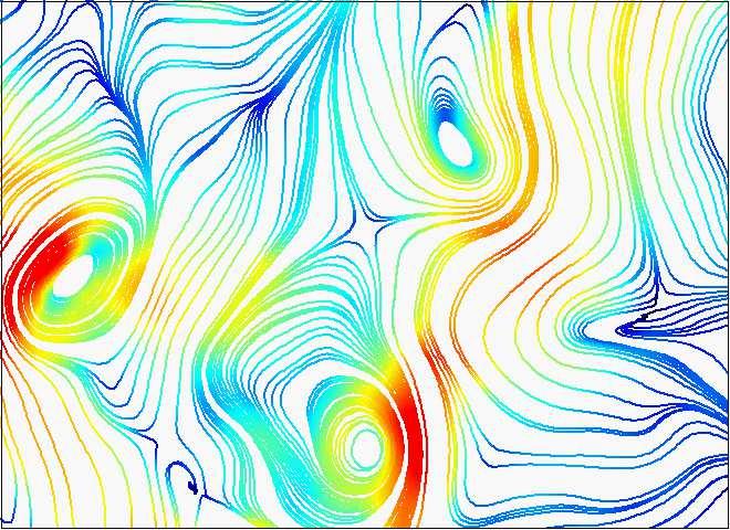
19 computed for the profiles at each streamwise station, the global stability is derived from the resulting streamwise distribution ofω. The local and global stability are connected through the concept of the global mode wavemaker. At the streamwise location of the wavemaker, the global mode frequency and growth rate is equal to the local absolute growth rate. There are two criteria that define the position of the wavemaker [5, 52].. A region of absolute instability is nested in a region of convective instability: The global mode frequency is then given by the saddle point criterion ω g =ω (x s ) with dω dx (x s)=, () which involves an analytical continuation ofω (x) in the complex x plane. The streamwise location x s determines the location of the global mode wavemaker where the global mode frequencyω g,r and growth rateω g,i is determined. 2. The region of absolute instability is attached or close to the flow inlet: The wavemaker is located at the inlet and the global mode frequency and growth rate is equal to the absolute frequency at the inlet ω g =ω (x=) and x s =. (2) The first scenario applies to the Kármán vortex street [6] and swirling jets with a detached vortex breakdown bubble [32, 4, 4]. In this work, both criteria come to play depending on specific combustor operating conditions. 5. Stability analysis of the isothermal flow the benchmark case The linear stability analysis is first applied to the flow field at isothermal conditions (case A). It serves as a test case for the stability analysis and for the adopted turbulence model. Figure 7 shows the measured mean flow field and the measured eddy viscosity utilizing eq. (5). As discussed in Sect. 3.2, the mean flow field is characterized by a cone-shaped swirling jet with an IRZ and ORZ. The flow features a self-excited PVC with a frequency of 35 Hz. The eddy viscosity distribution indicates strong turbulent fluctuations at the combustor inlet and in the region where the annular jet impinges the combustor walls. In these regions, the eddy viscosity is three orders of magnitude higher than the molecular viscosity. Radial profiles of the mean flow and eddy viscosity distribution are extracted for each streamwise location and fed into the stability solver. The absolute frequencyω is then derived from a spatio-temporal analysis of these profiles as 8
20 (a) 3 2 x/d y/d u /U (b) 3 2 x/d y/d ν t /ν Figure 7: Isothermal flow (case A): (a) contours of magnitude of the mean velocity and (b) the eddy viscosityν t derived from the triple-decomposed PIV measurements according to equ. (5). The mean flow streamlines indicate the inner and outer recirculation zones explained in Sect Figure 8 shows the real and imaginary part of the absolute frequency versus streamwise distance. In order to verify the turbulence models, computations were conducted for a quasi-laminar flow with Re=UD/ν and for the turbulent flow using the three different eddy viscosity models described in Sect For the quasi-laminar model, the absolute growth rateω,i is highest at the inlet and decreases continuously with downstream distance featuring a very large region of absolute instability (ω,i > ). When the fine-scale turbulence is taken into account, the growth rate is significantly decreased, as the additional viscosity generally dampens this type of instability. For the most comprehensive eddy viscosity modelν t (triple decomposition and least-square fit over all Reynolds stress components), the flow features a confined region of absolute instability with a transition from convective to absolute instability right at the combustor inlet. For both, the quasi-laminar and the turbulent flow analysis, the region of absolute instability is attached to the inlet. For this scenario the wavemaker is located at the upstream boundary of the absolute unstable region, which is right at the combustor inlet. The global mode frequency and growth rate are then given by the real and imaginary part of the absolute frequency at the inlet withω g =ω (x=). The resulting global oscillation 9
21 frequencies f=ω g,r /2π with and without the turbulence model are 36 Hz and 297 Hz, respectively. The value obtained with the turbulence model coincides remarkably well with the measured PVC oscillation frequency of 35 Hz (marked by the horizontal black line in Fig. 8). The quasi-laminar computations (Re = UD/ν) predict a globally unstable flow withω g,i =ω,i (x=)>, while the calculations with the turbulence model predict a globally marginally stable flow with ω g,i =ω,i (x=). The prediction of a marginally stable global mode is in good agreement with the mean field model proposed by Noack et al. [64] that was later confirmed numerically [65] and experimentally [66]. According to mean field theory, the limit-cycle oscillations of the global mode are accurately represented by a marginally stable global mode of the mean flow. Considering the simplified eddy viscosity models withν 2D t andν t given by equations (6) and (7), respectively, strong variations near the inlet become evident (see Fig. 8). The growth rates are significantly lower than for the comprehensive modelν t, whereas the frequencies remain unchanged. Now, the region of absolute instability is detached from the inlet and the global mode wavemaker is determined from criterion (). This would yield a wavemaker located at x/d.6 and a global mode frequency ofω r.2, which is far below the measured limitcycle. In fact, for both models, the correct frequency is still selected at the inlet, but the growth rates there are strongly underestimated. The present results suggest that the predicted absolute frequency does not depend on the turbulence model, but for a correct prediction of the growth rates the additional damping through the small-scale fluctuations must be considered. This is consistent with previously conducted stability analysis of similar configurations (with simplified or no turbulence models), where the predicted growth rates were wrong, but the frequencies were predicted correctly [42, 4, 23, 4, 59]. The good estimation of the limit-cycle gives credibility to the present turbulence model. The theoretical prediction is further validated by comparing the actual shape of the instability waves with the phase-averaged flow quantities. Therefore, the local eigenvalue problem is solved for the given global frequencyω g at each streamwise location. This so-called spatial stability analysis provides spatially growing (α i < ) and decaying (α i > ) instability waves for a given perturbation frequency. Figure 9 shows the results of this analysis for two selected profiles. Depicted are the amplitude distribution of the radial coherent velocity fluctuations at the combustor inlet (x/d =.4) and at a downstream location where the vortex shedding is strong (x/d=.8). At the inlet, the PVC is clearly indicated by the peak in the radial velocity magnitude on the jet centerline. This particular shape is well reproduced by the local stability eigemode at this streamwise location. At 2
22 (a) ω,id/u ν+ν t ν+ν 2D t ν+ν t ν (b) πSt PVC (measured) ω,rd/u x/d Figure 8: Isothermal flow: absolute growth rate (a) and frequency (b) derived from the linear stability analysis. Computations are conducted for a quasi-laminar flow with Re = UD/ν and for a turbulent flow with Re=UD/(ν+ν t ). For validation purpose, computations are repeated for simplified eddy viscosity modelsν 2D t andν t, as given by equ. (6-7).The measured PVC frequency is indicated by the black horizontal line (b). The global mode wave maker is locate at the inlet withω g =ω (x=). 2
23 ũr x/d=.4 measurements stability analysis.5.5 r/d x/d= r/d Figure 9: Profiles of the magnitude of the coherent radial velocity fluctuations derived from PIV and linear stability analysis. Profiles are taken at the most upstream measurement point and further downstream indicating the PVC at the inlet and the large-scale helical fluctuations in the shear layers further downstream. x/d=.8, fluctuations are concentrated in the periphery of the IRZ where the shear layers roll up to a helical vortex (see also Fig. 4). There the radial velocity fluctuations peak in the center of the annular jet at r/d=.75, which refers to the radial displacement of the entire annular jet column during the passage of a coherent structure. Again, these dynamics are very well captured by the stability eigenmode at this streamwise station. Besides the evaluation of the turbulence model, the analysis of the isothermal flow already indicates the importance of the inflow profiles for the formation of the PVC. With the wavemaker located at the inlet, the PVC frequency and growth rate strongly depend on the inflow conditions. Yet, the global flow oscillations are still driven by the downstream located region of absolute instability and associated upstream propagation of instability waves. Moreover, the analysis of the isothermal flow clearly demonstrates that the PVC at the inlet and the large-scale helical structures in between the IRZ and the ORZ correspond to the same global instability mode. 6. Stability analysis of the reacting flow flame-induced suppression of the PVC In this section, a stability analysis is performed for the reacting cases B and C. As discussed in Sect. 3.2, case B corresponds to the attached V-shaped flame without PVC, and case C corresponds to the detached M-shaped flame featuring a PVC at 595 Hz. The density fields displayed in Fig. 5 show that the attached flame B exhibits a strong radial density stratification at the nozzle lip, whereas the lifted flame C features smooth radial density gradients near the burner nozzle. 22
24 The density field contributes to the pressure term of the stability equations (3) and through a modification of the kinematic viscosity. Due to the baroclinic torque, the stratification of density may crucially affect the growth rates of the instability. A radial density gradient that is co-signed with the radial gradient of axial velocity acts typically dampening on the instability and vice versa. As a consequence, the density field destabilizes hot jets and cold wakes while it stabilizes cold jets and hot wakes [38, 39]. In swirl-stabilized combustion, the cold annular jet emanates into the hot combustion chamber. If the flame is located close to the inlet, the temperature difference between the incoming unburned gas and the reactants in the IRZ form a strong radial density gradient. The resulting hot wake flow is thereby more stable than the isothermal flow, which may lead to the suppression of the PVC [4, 4]. In contrast, if the flame is located further downstream, the incoming cold fluid mixes gradually with the hot burned gas in the IRZ and the radial density gradients are smooth. In this case the flow field is similarly unstable as the nonreacting flow and the PVC prevails. This scenario applies to the configurations considered here. Figure shows the results of the stability analysis of the attached (case B) and detached (case C) flame. Computations are conducted with and without taking the density field into account. For the attached flame, which features no PVC, the absolute growth rate is significantly decreased when taking the density field into consideration. Particularly at the inlet, where the density stratification is strong, the growth rate is significantly reduced. The comparison between the isothermal and stratified computations reveal that the flow field itself is globally unstable with the wavemaker located at the inlet, and the non-existence of the PVC is only reproduced if the density field is taken into consideration. This strongly suggests that the PVC that exists at isothermal conditions is suppressed by the density stratification in the inlet region induced by the attached flame. The confined region of absolute instability that remains further downstream is too small to trigger a global instability. The corresponding wavermaker is derived from criterion () that applies for absolutely unstable flows nested within a convectively unstable domain. It is located at x s /D=.25 with a global mode frequency ofω g =.39+i.27, indicating a marginally unstable global mode at very low frequency (24 Hz). Since the experiments do not indicate any low frequency oscillations this mode is not likely to represent a limit-cycle oscillation, and it must correspond to another mode at the border of instability. For the detached flame in case C, the influence of the density field on the flow stability is less significant. The stability analysis of the stratified flow reveals a semifinite region of absolute instability (Fig. c). Analogous to the isothermal 23
25 (a).5 attached flame (case B) (c) detached flame (case C) ω,id/u.5 (b) stratified ρ=const. (d) 2πSt PVC (measured) ω,rd/u x/d.5.5 x/d Figure : Reacting flow: absolute growth rate (a-b) and frequency (c-d) derived from the linear stability analysis for case B (a,c) and case C (b,d). Computations are conducted for the reacting flows assuming a homogeneous density field and with the actually measured density field. For case B the PVC instability at the inlet is suppressed by the density field. For case C the measured PVC frequency is indicated by the black horizontal line (d). For case C, the global mode wavemaker is located at the inlet withω g =ω (x=). 24
26 case A, the wavemaker is located at the inlet with the global mode frequency ω g =ω (x=). The resulting global mode oscillation frequency f=ω g,r /2π=63 Hz agrees well with the measured PVC frequency of 595 Hz (cf. Fig. d), and the marginal instabilityω g,i is confirmed. By neglecting the density stratification for case C, the absolute growth rate at the inlet is predicted somewhat too high, while the PVC frequency is predicted much too low. The analysis reveals that the density stratification in case C does not affect the global mode growth rate, but it significantly alters the oscillation frequency. Since the radial density gradients are small in between the IRZ and the annular jet, the effect on the PVC frequency must be caused by the density differences between the ORZ and the annular jet. The linear stability analysis of the reacting cases B and C has shown that the mean flow and density field determines the occurrence or absence of the PVC. The PVC in turn, however, influences the flame shape and thereby the flow and density field. The question whether a flame with or without PVC will form at a certain condition thus depends on a complex unsteady interplay of flame propagation and the flow/density field. In the next section, this interplay will be illustrated for a bi-stable condition where the PVC forms intermittently. 7. Transient formation of the PVC 7.. Bi-stable behavior of flame D Until now, the two stable flame types, namely the V-shaped form without PVC and the lifted, M-shaped form exhibiting a PVC, have been analyzed. Between the two respective ranges of conditions shown in Fig. 2, transitional bi-stable cases are found where the flame alternates randomly between the two forms. This implies that a PVC is repeatedly formed and suppressed, and therefore the bi-stable cases allow studying the transient formation of a PVC and its role in the transition of flame type. A particular question is whether the flame form first changes and then the PVC is formed, or if at first the PVC forms and this then triggers the change of flame shape. The results might be relevant to other swirl combustors where bi-stable flames have been reported [67, 68, 69, 7, 9, 7]. E.g. Hermeth et al. [7] observe in their LES very similar flame-shape bifurcations than reported here, however not providing an explanation based on flow stability considerations. In this section, the dynamics of PVC formation at a bi-stable condition is studied using the time-resolved, simultaneous PIV and OH-PLIF technique described in Sect The selected bi-stable condition is labeled as case D and specified in Table. As marked in Fig. 2, it has the same equivalence ratioφ=.7 as cases 25
, axial inflow velocity (blue) and OH-PLIF signal at the nozzle (white). The exemplary measurements are adopted from Fig. 6.")

27 Flame B: attached, V-shaped, without PVC y= Flame C: detached, M-shaped, with PVC y= left right left right Flow asymmetry Inflow velocity Flame attached/detached Figure : Selected regions for the determination of flow asymmetry (red), axial inflow velocity (blue) and OH-PLIF signal at the nozzle (white). The exemplary measurements are adopted from Fig. 6. B and C and an intermediate thermal power of P th =2 kw. At this condition, the flame alternates about once per second between a V-shaped form similar to case B, and an M-shaped form similar to case C. The analysis is based on three quantities, which are estimated from the discrete fields of velocity and OH as illustrated in Fig.. The first quantity a(t) is the asymmetry of the flow field above the nozzle (marked red). It is a measure of the presence and strength of the PVC. The asymmetry a(t) is calculated as the squared difference between the left and right half of the flow field, i.e., a(t)= x,y u(x, y, t) u(x, y, t) 2 (the elements of u=(u x, u r, u θ ) T are the axial, radial, and azimuthal velocity component, respectively). The value of a(t) is low for the symmetric flow without PVC and high when the asymmetric vortex pattern of the PVC appears. The second quantity b(t) is the OH-PLIF signal in the zone directly above the nozzle (marked white). It is calculated as the sum of counts g in this region of the OH-PLIF image, i.e., b(t)= x,y g(x, y, t). Values of b(t) are high 26
![No PVC PVC formation Stable PVC 2 Precursor events Average OH-CL (t<3 ms) Intensity [a.u.].5 Average OH-CL (t>6 ms).](/docs-images/80/81959038/images/28-0.jpg "5 2 3 t [ms] 4 5 6 7 Attached flame (without PVC) Flame transition Detached flame (with PVC) Figure 2: Temporal evolution of flow asymmetry (red), axial inflow velocity (blue) and OH-PLIF signal at")
 is the flow velocity into the combustion chamber, taken over the region above the nozzle (marked blue), i.e., c(t)= x,y u x (x, y, t).")
28 No PVC PVC formation Stable PVC 2 Precursor events Average OH-CL (t<3 ms) Intensity [a.u.].5 Average OH-CL (t>6 ms) t [ms] Attached flame (without PVC) Flame transition Detached flame (with PVC) Figure 2: Temporal evolution of flow asymmetry (red), axial inflow velocity (blue) and OH-PLIF signal at the nozzle (black) during the transition from a V-shaped flame to an M-shaped flame. when the flame is attached and low when it is detached. The third quantity c(t) is the flow velocity into the combustion chamber, taken over the region above the nozzle (marked blue), i.e., c(t)= x,y u x (x, y, t). While the temporal average of c(t) is similar for both flame forms, temporary fluctuations might influence the transition. In the following discussion, for all three quantities only relative changes are considered, and therefore they will be plotted in arbitrary units (a.u.). Figure 2 shows the dynamics during the transition from V-shape to M-shape. For t<3 ms, the V-flame remains largely stable. Then, starting at t 32 ms, the asymmetry (red) increases indicating the formation of the PVC. The flame remains attached until t 4 ms as indicated by the OH signal at the nozzle (black). For t>5 ms, a detached, M-shaped flame with PVC has stabilized. The temporal dynamics show that at first the PVC is formed, and then the attached flame lifts and changes its shape. Prior to the transition, three precursor events at t 5, 7 and 28 ms can be observed where a PVC starts to form, but is quickly suppressed again. The cause for the onset of the PVC oscillations remains unclear at first and thus requires a more detailed investigation of the PIV and OH-PLIF image sequences. In the following, we first focus on to the precursor events and thereafter on the transition Precursor event The dynamics of the precursor event at around t=5 ms is plotted in more detail in Fig. 3. It shows that the inflow rate (blue) fluctuates randomly, and that these fluctuations correlate oppositely with the OH at the nozzle (black). This is 27
29 .5 Images Fig [ms] Transient PVC formation Intensity [a.u.].5 Slight lift-off events t [ms] 7 8 Figure 3: Temporal evolution of flow asymmetry (red), axial inflow velocity (blue) and OH-PLIF signal at the nozzle (black) during the precursor event around t=5 ms. expected since the inflowing unburned gas contains no OH. The random nature of the inflow fluctuations suggests that these are caused by turbulent motion of the unburned inflow. The corresponding PIV and OH-PLIF image sequences are shown in Fig. 4. In the right column PIV particle images, which were spatially smoothed in order to blur the intensity spikes of individual tracer particles, are plotted as an approximate marker of the gas density. This is based on findings that changes of gas density in flames, e.g. between burned und unburned gas, lead to corresponding changes of PIV particle density [72, 73] (see also Sect. 3.4). It is seen that, as expected from the discussion in Sect. 3.3, the black zones in the OH-PLIF images correspond to relatively dense unburned gas, whereas the density has decreased significantly in the burned gas where OH is present. The image sequences show that at t=3.2 ms, the flow field is largely symmetric without PVC and the flame is attached. At t=3.9 ms, the inflow rate increases abruptly, which leads to a quenching of the flame root at the bottom. The PIV particle images reveal that this entails an increased amount of unburned gas near the nozzle (marked with an ellipse). The stability analysis in Sect. 6 has shown that the radial density gradients at the nozzle dampen the PVC. The reduced radial density gradients near the nozzle at t=3.9 ms may thus enable the formation of the PVC. Indeed, it is seen that at t=4.4 and 4.7 ms, a PVC has formed. It is noted that this causality, namely that an intermittent increase of unburned gas at the nozzle is followed by a transient formation of a PVC, is observed every ms during the V-shaped phases of case D, including the precursor events at t=7 and 28 ms 28


30 Velocity + OH-PLIF 3.2 ms Velocity (Streamlines) PIV particle images (smoothed) Attached flame 3.9 ms Extinction at flame root Symmetric flow Increased unburned gas 4.4 ms 4.7 ms Reignition Zig-zag vortices (Helical PVC) 5.4 ms Attached flame Symmetric flow 2 3 u [m/s] max Figure 4: Time-resolved PIV and OH-PLIF measurement during the precursor event around t=5 ms. The PIV particle density images are used as an approximate marker of gas density. marked in Fig. 2. Subsequently at t=4.7 ms, however, the flame root re-ignites and therefore, the region of unburned gas is reduced again. At t=5.4 ms, a larger zone of low-density burned gas above the nozzle has re-established and, consistent with the stability analysis in Sect. 6, the PVC has disappeared. 29
31 Intensity [a.u.] Images Fig PVC formation Transient lift-off t [ms] [ms] Flame transition 48 Figure 5: Temporal evolution of flow asymmetry (red), axial inflow velocity (blue) and OH-PLIF signal at the nozzle (black) during the transition event Dynamics of flame transition The dynamics of the flame transition and PVC formation from t=34 to t=48 ms is plotted in Fig. 5 and the corresponding image sequence is shown in Fig. 6. Until t=37.7 ms, the flame is attached and the flow does not exhibit a PVC. At t=38. ms, an increased inflow occurs like at the onset of the precursor event (t=3.9 ms) described above. The higher inflow again causes quenching at the flame root and an increased amount of unburned gas near the nozzle. Like in the precursor event, the increased density of unburned gas near the nozzle is followed by the formation of a PVC at t=38.5 ms. Other than in the precursor event, however, the PVC now persists slightly longer. Apparently, at this stage the PVC is at the border of stability, and the decision whether it persists or disappears again depends on small local variations of the density and flow fields. During its initial formation at t=38.5 and 4. ms, the PVC exhibits the typical zig-zag vortex pattern, but no stagnation point has yet appeared and therefore the flame is still attached. As described in Sect. 3.3 and Ref. [7], the unsteady lower stagnation point is an important feature of the PVC as it determines the position of the flame root. Starting at t=4.2 ms, an unsteady stagnation point appears and accordingly, the flame root detaches and lifts off. This further enlarges the region of unburned gas above the nozzle, and presumably further supports the PVC formation until it is fully established at t 48 ms. In conclusion, it is certainly difficult to fully characterize the transition mech- 3


32 37.7 ms Attached flame Symmetric flow 38. ms Extinction at flame root 38.5 ms Zig-zag vortices (Helical PVC) 4. ms Reverse flow 4.2 ms Flame lift-off Stagnation point 42. ms 44. ms 46.6 ms Detached Flame Figure 6: Time-resolved PIV and OH-PLIF measurement during the transition event. The velocity color scale is the same as in Fig. 4. 3
The original publication is available at
 M. Stöhr, Z. Yin and W. Meier, Interaction between velocity fluctuations and equivalence ratio fluctuations during thermoacoustic oscillations in a partially premixed swirl combustor, Proceedings of the
Simultaneous Velocity and Concentration Measurements of a Turbulent Jet Mixing Flow
 Simultaneous Velocity and Concentration Measurements of a Turbulent Jet Mixing Flow HUI HU, a TETSUO SAGA, b TOSHIO KOBAYASHI, b AND NOBUYUKI TANIGUCHI b a Department of Mechanical Engineering, Michigan
FLAME AND FLOW DYNAMICS OF A SELF-EXCITED, STANDING WAVE CIRCUMFERENTIAL INSTABILITY IN A MODEL ANNULAR GAS TURBINE COMBUSTOR
 Proceedings of the ASME Turbo Expo 2013, Power for Land, Sea, and Air GT2013 June 3-7, 2013, San Antonio, Texas GT2013-95897 FLAME AND FLOW DYNAMICS OF A SELF-EXCITED, STANDING WAVE CIRCUMFERENTIAL INSTABILITY
Version Accepted Manuscript/Post-print
 TSpace Research Repository tspace.library.utoronto.ca Thermo-acoustic velocity coupling in a swirl stabilized gas turbine model combustor Vincent Caux-Brisebois, Adam M. Steinberg, Christoph M. Arndt,
Isaac Boxx 1*, Campbell Carter 2, Michael Stöhr 1, Wolfgang Meier 1
 Experimental Study of Auto-Ignition Phenomena in Swirl-Stabilized LPP Flames in Gas Turbine Model Combustors using khz Framerate OH-PLIF and Stereo-PIV Isaac Boxx 1*, Campbell Carter 2, Michael Stöhr 1,
Thermoacoustic Instabilities Research
 Chapter 3 Thermoacoustic Instabilities Research In this chapter, relevant literature survey of thermoacoustic instabilities research is included. An introduction to the phenomena of thermoacoustic instability
SIMULTANEOUS VELOCITY AND CONCENTRATION MEASUREMENTS OF A TURBULENT JET MIXING FLOW
 Proceedings of International Symposium on Visualization and Image in Transport Phenomena, Turkey, -9 Oct. SIMULTANEOUS VELOCITY AND CONCENTRATION MEASUREMENTS OF A TURBULENT JET MIXING FLOW Hui HU a, Tetsuo
Large Eddy Simulation of Piloted Turbulent Premixed Flame
 Large Eddy Simulation of Piloted Turbulent Premixed Flame Veeraraghava Raju Hasti, Robert P Lucht and Jay P Gore Maurice J. Zucrow Laboratories School of Mechanical Engineering Purdue University West Lafayette,
A. Aleksandrov, H. Bockhorn
 Experimental Investigation of the impact of imposed air inlet velocity oscillations on Soot Formation and Oxidation using an advanced 2-Colour-TIRE-LII A. Aleksandrov, H. Bockhorn Engler-Bunte-Institute,
THE EFFECT OF SAMPLE SIZE, TURBULENCE INTENSITY AND THE VELOCITY FIELD ON THE EXPERIMENTAL ACCURACY OF ENSEMBLE AVERAGED PIV MEASUREMENTS
 4th International Symposium on Particle Image Velocimetry Göttingen, Germany, September 7-9, 00 PIV 0 Paper 096 THE EFFECT OF SAMPLE SIZE, TURBULECE ITESITY AD THE VELOCITY FIELD O THE EXPERIMETAL ACCURACY
IMPACT OF FLOW NON-AXISYMMETRY ON SWIRLING FLOW DYNAMICS AND RECEPTIVITY TO ACOUSTICS. B Azimuthal mode shape of the m-th mode U O
 Proceedings of the ASME Turbo Expo 2015 GT2015 June 15-19, 2015, Montreal, Canada GT2015-43377 IMPACT OF FLOW NON-AXISYMMETRY ON SWIRLING FLOW DYNAMICS AND RECEPTIVITY TO ACOUSTICS Samuel Hansford and
C. M. Arndt, M. Severin, C. Dem, M. Stöhr, A. M. Steinberg, W. Meier
 C. M. Arndt, M. Severin, C. Dem, M. Stöhr, A. M. Steinberg, W. Meier Experimental analysis of thermo-acoustic instabilities in a generic gas turbine combustor by phase-correlated PIV, chemiluminescence,
Experimental Study on the Non-reacting Flowfield of a Low Swirl Burner
 Experimental Study on the Non-reacting Flowfield of a Low Swirl Burner Hang Yin & Ren Dai School of Energy and Powering Engineering, University of Shanghai for Science and Technology Box 25, 516# Jungong
PIV measurements of cold flow field in a partially premixed bluff body burner M. Dutka, 1, M. Ditaranto 2, T. Løvås 1
 PIV measurements of cold flow field in a partially premixed bluff body burner M. Dutka, 1, M. Ditaranto 2, T. Løvås 1 1 Department of Energy and Process Engineering, Norwegian University of Science and
Dynamics of Large Scale Motions in Bubble-Driven Turbulent Flow
 Dynamics of Large Scale Motions in Bubble-Driven Turbulent Flow Kyung Chun Kim School of Mechanical Engineering, Pusan National University Jangjeon-dong, Geumjeong-gu, Pusan, 609-735, Korea kckim@pusan.ac.kr
SIMULATION OF PRECESSION IN AXISYMMETRIC SUDDEN EXPANSION FLOWS
 Second International Conference on CFD in the Minerals and Process Industries CSIRO, Melbourne, Australia 6-8 December 1999 SIMULATION OF PRECESSION IN AXISYMMETRIC SUDDEN EXPANSION FLOWS Baoyu GUO, Tim
Large Eddy Simulation of Flame Flashback by Combustion Induced Vortex Breakdown
 June 30 - July 3, 2015 Melbourne, Australia 9 1C-5 Large Eddy Simulation of Flame Flashback by Combustion Induced Vortex Breakdown Eike Tangermann Institut für Mathematik und Rechneranwendung Universität
Mixing Enhancement of Coaxial Jet with Arrayed Flap Actuators for Active Control of Combustion Field
 Proceedings of the 2nd Symposium on Smart Control of Turbulence, Tokyo, Japan, March 4-6, 2001. Mixing Enhancement of Coaxial Jet with Arrayed Flap Actuators for Active Control of Combustion Field Naoki
(U c. t)/b (U t)/b
/b (U t)/b") DYNAMICAL MODELING OF THE LARGE-SCALE MOTION OF A PLANAR TURBULENT JET USING POD MODES. S. Gordeyev 1 and F. O. Thomas 1 University of Notre Dame, Notre Dame, USA University of Notre Dame, Notre Dame,
DYNAMICAL MODELING OF THE LARGE-SCALE MOTION OF A PLANAR TURBULENT JET USING POD MODES. S. Gordeyev 1 and F. O. Thomas 1 University of Notre Dame, Notre Dame, USA University of Notre Dame, Notre Dame,
A Novel FEM Method for Predicting Thermoacoustic Combustion Instability
 Excerpt from the Proceedings of the COMSOL Conference 009 Milan A Novel FEM Method for Predicting Thermoacoustic Combustion Instability G. Campa *, S.M. Camporeale Politecnico di Bari * campa@imedado.poliba.it,
Transition of laminar pre-mixed flames to turbulence - induced by sub-breakdown applied voltage
 Transition of laminar pre-mixed flames to turbulence - induced by sub-breakdown applied voltage Biswa N. Ganguly Aerospace Systems Directorate, Air Force Research Laboratory WPAFB OH USA and Jacob Schmidt
Flow Structure Investigations in a "Tornado" Combustor
 Flow Structure Investigations in a "Tornado" Combustor Igor Matveev Applied Plasma Technologies, Falls Church, Virginia, 46 Serhiy Serbin National University of Shipbuilding, Mikolayiv, Ukraine, 545 Thomas
Fluid Dynamics Exercises and questions for the course
 Fluid Dynamics Exercises and questions for the course January 15, 2014 A two dimensional flow field characterised by the following velocity components in polar coordinates is called a free vortex: u r
Lecture 9 Laminar Diffusion Flame Configurations
 Lecture 9 Laminar Diffusion Flame Configurations 9.-1 Different Flame Geometries and Single Droplet Burning Solutions for the velocities and the mixture fraction fields for some typical laminar flame configurations.
Journal of Fluid Science and Technology
 Science and Technology LDV and PIV Measurements of the Organized Oscillations of Turbulent Flow over a Rectangular Cavity* Takayuki MORI ** and Kenji NAGANUMA ** **Naval Systems Research Center, TRDI/Ministry
AFRL-AFOSR-UK-TR
 AFRL-AFOSR-UK-TR-2011-0060 Experimental Study of Auto-Ignition Phenomena in Swirl- Stabilized LPP Flames in Gas Turbine Model Combustors using khz Framerate OH-PLIF and Stereo-PIV Isaac G. Boxx Deutsches
The original publication is available at
 Isaac Boxx, Michael Stöhr, Campbell Carter*, Wolfgang Meier, Temporally resolved planar measurements of transient phenomena in a partially pre-mixed swirl flame in a gas turbine model combustor, Combust.
Erratum to: High speed mixture fraction and temperature imaging of pulsed, turbulent fuel jets auto igniting in high temperature, vitiated co flows
 DOI 10.1007/s00348-015-2101-9 ERRATUM Erratum to: High speed mixture fraction and temperature imaging of pulsed, turbulent fuel jets auto igniting in high temperature, vitiated co flows Michael J. Papageorge
Active Control of Separated Cascade Flow
 Chapter 5 Active Control of Separated Cascade Flow In this chapter, the possibility of active control using a synthetic jet applied to an unconventional axial stator-rotor arrangement is investigated.
Numerical Studies of Supersonic Jet Impingement on a Flat Plate
 Numerical Studies of Supersonic Jet Impingement on a Flat Plate Overset Grid Symposium Dayton, OH Michael R. Brown Principal Engineer, Kratos/Digital Fusion Solutions Inc., Huntsville, AL. October 18,
Experimental investigation of flow control devices for the reduction of transonic buffeting on rocket afterbodies
 Experimental investigation of flow control devices for the reduction of transonic buffeting on rocket afterbodies F.F.J. Schrijer 1, A. Sciacchitano 1, F. Scarano 1 1: Faculty of Aerospace Engineering,
PIV measurements of flow structures in a spray dryer
 Downloaded from orbit.dtu.dk on: Nov 19, 218 PIV measurements of flow structures in a spray dryer Meyer, Knud Erik; Velte, Clara Marika; Ullum, Thorvald Published in: Proceedings of PIV'11 Publication
Citation information:
 Citation information: B. D. Geraedts, C. M. Arndt, and A. M. Steinberg, "Rayleigh Index Fields in Helically Perturbed Swirl-Stabilized Flames Using Doubly Phase Conditioned OH* Chemiluminescence Tomography",
Experiments on the perturbation of a channel flow by a triangular ripple
 Experiments on the perturbation of a channel flow by a triangular ripple F. Cúñez *, E. Franklin Faculty of Mechanical Engineering, University of Campinas, Brazil * Correspondent author: fernandodcb@fem.unicamp.br
3kHz PIV / OH-PLIF measurements in a gas turbine combustor at elevated pressure
 I. Boxx, C. Slabaugh, P. Kutne, R.P. Lucht, W. Meier 3kHz PIV / OH-PLIF measurements in a gas turbine combustor at elevated pressure Published in the Proceedings of the Combustion Institute, 2015. Volume
HEAT TRANSFER IN A RECIRCULATION ZONE AT STEADY-STATE AND OSCILLATING CONDITIONS - THE BACK FACING STEP TEST CASE
 HEAT TRANSFER IN A RECIRCULATION ZONE AT STEADY-STATE AND OSCILLATING CONDITIONS - THE BACK FACING STEP TEST CASE A.K. Pozarlik 1, D. Panara, J.B.W. Kok 1, T.H. van der Meer 1 1 Laboratory of Thermal Engineering,
PIV measurements of turbulence in an inertial particle plume in an unstratified ambient
 PIV measurements of turbulence in an inertial particle plume in an unstratified ambient D.B. Bryant & S.A. Socolofsky Zachry Department of Civil Engineering, Texas A&M University, USA ABSTRACT: A high-speed
Turbulent Boundary Layers & Turbulence Models. Lecture 09
 Turbulent Boundary Layers & Turbulence Models Lecture 09 The turbulent boundary layer In turbulent flow, the boundary layer is defined as the thin region on the surface of a body in which viscous effects
CHAPTER 7 SEVERAL FORMS OF THE EQUATIONS OF MOTION
 CHAPTER 7 SEVERAL FORMS OF THE EQUATIONS OF MOTION 7.1 THE NAVIER-STOKES EQUATIONS Under the assumption of a Newtonian stress-rate-of-strain constitutive equation and a linear, thermally conductive medium,
Topology and Brush Thickness of Turbulent Premixed V-shaped Flames
 Flow Turbulence Combust (2014) 93:439 459 DOI 10.1007/s10494-014-9563-3 Topology and Brush Thickness of Turbulent Premixed V-shaped Flames S. Kheirkhah Ö. L. Gülder Received: 19 December 2013 / Accepted:
Chapter 7. Discussion, Conclusions and Recommendations
 Chapter 7 Discussion, Conclusions and Recommendations 286 7.1 Overview of experimental results 7.1.1 Free vortex geometry Free vortex geometry flows exhibit a wide range of behavior depending not only
Intensely swirling turbulent pipe flow downstream of an orifice: the influence of an outlet contraction
 13 th Int. Symp. on Appl. Laser Techniques to Fluid Mechanics, Lisbon, Portugal, June 26-29, 26 Intensely swirling turbulent pipe flow downstream of an orifice: the influence of an outlet contraction Marcel
Central recirculation zones and instability waves in internal swirling flows with an annular entry
 PHYSICS OF FLUIDS 30, 013602 (2018) Central recirculation zones and instability waves in internal swirling flows with an annular entry Yanxing Wang and Vigor Yang a) School of Aerospace Engineering, Georgia
White Paper FINAL REPORT AN EVALUATION OF THE HYDRODYNAMICS MECHANISMS WHICH DRIVE THE PERFORMANCE OF THE WESTFALL STATIC MIXER.
 White Paper FINAL REPORT AN EVALUATION OF THE HYDRODYNAMICS MECHANISMS WHICH DRIVE THE PERFORMANCE OF THE WESTFALL STATIC MIXER Prepared by: Dr. Thomas J. Gieseke NUWCDIVNPT - Code 8233 March 29, 1999
Validation 3. Laminar Flow Around a Circular Cylinder
 Validation 3. Laminar Flow Around a Circular Cylinder 3.1 Introduction Steady and unsteady laminar flow behind a circular cylinder, representing flow around bluff bodies, has been subjected to numerous
High-Speed PIV Investigation of Coherent Structures in a Swirl-Stabilized Combustor Operating at Dry and Steam-Diluted Conditions
 Lisbon, Portugal, 9-1 July, 1 High-Speed PIV Investigation of Coherent Structures in a Swirl-Stabilized Combustor Operating at Dry and Steam-Diluted Conditions Steffen Terhaar 1,*, Christian Oliver Paschereit
XXXVIII Meeting of the Italian Section of the Combustion Institute
 Coupling a Helmholtz solver with a Distributed Flame Transfer Function (DFTF) to study combustion instability of a longitudinal combustor equipped with a full-scale burner D. Laera*, S.M. Camporeale* davide.laera@poliba.it
Numerical Simulation of Unsteady Flow with Vortex Shedding Around Circular Cylinder
 Numerical Simulation of Unsteady Flow with Vortex Shedding Around Circular Cylinder Ali Kianifar, Edris Yousefi Rad Abstract In many applications the flow that past bluff bodies have frequency nature (oscillated)
arxiv: v2 [physics.flu-dyn] 12 Sep 2016
![arxiv: v2 [physics.flu-dyn] 12 Sep 2016](/thumbs/91/106794129.jpg "arxiv: v2 [physics.flu-dyn] 12 Sep 2016") The impact of heating the breakdown bubble on the global mode of a swirling jet: Experiments and linear stability analysis. Lothar Rukes,, a) Moritz Sieber, C. Oliver Paschereit, and Kilian Oberleithner
The impact of heating the breakdown bubble on the global mode of a swirling jet: Experiments and linear stability analysis. Lothar Rukes,, a) Moritz Sieber, C. Oliver Paschereit, and Kilian Oberleithner
Spontaneous Oscillations in LNGT Combustors: CFD Simulation
 Spontaneous Oscillations in LNGT Combustors: CFD Simulation V. Di Sarli, A. Di Benedetto and F. S. Marra Istituto di Ricerche sulla Combustione - C.N.R., Naples - ITALY INTRODUCTION The development of
Chapter 4. Experimental Results - Statistics
 Chapter 4 Experimental Results - Statistics 13 4.1 Overview The present chapter includes a presentation and discussion of the results for two major geometries. For the first geometry, the swirler center
High-Speed Thermographic Particle Image Velocimetry
 High-Speed Thermographic Particle Image Velocimetry Christopher Abram, Benoit Fond, Andrew L Heyes, Frank Beyrau * Department of Mechanical Engineering, Imperial College London, UK * corresponding author:
D. C. Lewellen and W. S. Lewellen West Virginia University, Morgantown, WV.
 13.5 ON THE LIMITS TO NEAR-SURFACE INTENSIFICATION OF TORNADO VORTICES D. C. Lewellen and W. S. Lewellen West Virginia University, Morgantown, WV. 1 INTRODUCTION In a tornadic supercell velocities are
Effect of blowing rate on the film cooling coverage on a multi-holed plate: application on combustor walls
 Effect of blowing rate on the film cooling coverage on a multi-holed plate: application on combustor walls P. Miron 1,2, C. Berat 1 & V. Sabelnikov 3 1 TURBOMECA-Bordes, France 2 LaTEP, Université de Pau
The original publication is available at
 C.M. Arndt, M.J. Papageorge, F. Fuest, J.A. Sutton, W. Meier, M. Aigner, The role of temperature, mixture fraction, and scalar dissipation rate on transient methane injection and auto-ignition in a jet
Impact of fuel composition on the recirculation zone structure and its role in lean premixed flame anchoring
 Impact of fuel composition on the recirculation zone structure and its role in lean premixed flame anchoring Seunghyuck Hong, Santosh J. Shanbhogue, Ahmed F. Ghoniem Reacting Gas Dynamics Laboratory, Center
Percolation: Statistical Description of a Spatial and Temporal Highly Resolved Boundary Layer Transition
 Percolation: Statistical Description of a Spatial and Temporal Highly Resolved Boundary Layer Transition Tom T. B. Wester, Dominik Traphan, Gerd Gülker and Joachim Peinke Abstract In this article spatio-temporally
and Sagar R. Kulkarni 6 Process and Energy Department, Delft University of Technology, Delft, The Netherlands
 Experimental and numerical investigation of spray characteristics in a new FLOX based combustor for liquid fuels for Micro Gas Turbine Range Extender (MGT-REX). James D. Gounder 1, Anton Zizin 2, Oliver
PROPERTIES OF THE FLOW AROUND TWO ROTATING CIRCULAR CYLINDERS IN SIDE-BY-SIDE ARRANGEMENT WITH DIFFERENT ROTATION TYPES
 THERMAL SCIENCE, Year, Vol. 8, No. 5, pp. 87-9 87 PROPERTIES OF THE FLOW AROUND TWO ROTATING CIRCULAR CYLINDERS IN SIDE-BY-SIDE ARRANGEMENT WITH DIFFERENT ROTATION TYPES by Cheng-Xu TU, a,b Fu-Bin BAO
Vortex-acoustic lock-on in bluff-body and backward-facing step combustors
 Sādhanā Vol.32,Parts1&2, February April 2007, pp. 145 154. Printed in India Vortex-acoustic lock-on in bluff-body and backward-facing step combustors S R CHAKRAVARTHY 1, R SIVAKUMAR 2 and O J SHREENIVASAN
DEVELOPMENT OF CFD MODEL FOR A SWIRL STABILIZED SPRAY COMBUSTOR
 DRAFT Proceedings of ASME IMECE: International Mechanical Engineering Conference & Exposition Chicago, Illinois Nov. 5-10, 2006 IMECE2006-14867 DEVELOPMENT OF CFD MODEL FOR A SWIRL STABILIZED SPRAY COMBUSTOR
S. Kadowaki, S.H. Kim AND H. Pitsch. 1. Motivation and objectives
 Center for Turbulence Research Annual Research Briefs 2005 325 The dynamics of premixed flames propagating in non-uniform velocity fields: Assessment of the significance of intrinsic instabilities in turbulent
Flow Control around Bluff Bodies by Attached Permeable Plates
 Flow Control around Bluff Bodies by Attached Permeable Plates G. M. Ozkan, H. Akilli Abstract The aim of present study is to control the unsteady flow structure downstream of a circular cylinder by use
Liquid-Rocket Transverse Triggered Combustion Instability: Deterministic and Stochastic Analyses
 Liquid-Rocket Transverse Triggered Combustion Instability: Deterministic and Stochastic Analyses by W. A. Sirignano Mechanical and Aerospace Engineering University of California, Irvine Collaborators:
Evolution and transition mechanisms of internal swirling flows with tangential entry
 PHYSICS OF FLUIDS 30, 013601 (2018) Evolution and transition mechanisms of internal swirling flows with tangential entry Yanxing Wang, Xingjian Wang, and Vigor Yang a) School of Aerospace Engineering,
Investigation of the non-reactive flow in a swirling burner
 ISSN 1392-1207. MECHANIKA. Investigation of the non-reactive flow in a swirling burner F. Bode*, C. Giurgea**, V. Hodor***, P.Unguresan**** * Technical University of Cluj-Napoca, Department of Thermotechnics,
LDA-Measurements of Jets in Crossflow for Effusion Cooling Applications
 LDA-Measurements of Jets in Crossflow for Effusion Cooling Applications by K. M. Bernhard Gustafsson Department of Thermo and Fluid Dynamics Chalmers University of Technology SE-41296 Göteborg, SWEDEN
Basic Fluid Mechanics
 Basic Fluid Mechanics Chapter 6A: Internal Incompressible Viscous Flow 4/16/2018 C6A: Internal Incompressible Viscous Flow 1 6.1 Introduction For the present chapter we will limit our study to incompressible
Large Eddy Simulations for the Flame Describing Function of a premixed turbulent swirling flame
 Large Eddy Simulations for the Flame Describing Function of a premixed turbulent swirling flame Davide LAERA, and Aimee S. MORGANS Department of Mechanical Engineering, Imperial College London, London,
Parabolized Stability Analysis of Jets Issuing from Serrated Nozzles
 Parabolized Stability Analysis of Jets Issuing from Serrated Nozzles Aniruddha Sinha, Hao Xia and Tim Colonius Abstract Jets issuing from serrated nozzles have a correspondingly serrated timeaveraged flow
Flow Characteristics around an Inclined Circular Cylinder with Fin
 Lisbon, Portugal, 7- July, 28 Flow Characteristics around an Inclined Circular Cylinder with Fin Tsuneaki ISHIMA, Takeshi SASAKI 2, Yoshitsugu GOKAN 3 Yasushi TAKAHASHI 4, Tomio OBOKATA 5 : Department
High-speed laser diagnostics for the study of flame dynamics in a lean premixed gas turbine model combustor
 I. Boxx, C. Arndt, C.D. Carter, W. Meier High-speed laser diagnostics for the study of flame dynamics in a lean premixed gas turbine model combustor Experiments in Fluids, 52:3 pp. 555-567. (2012) DOI:
Analysis of Interaction between Acoustic Waves and CH 4 /Air Laminar Partially Premixed Flames by means of OH-PLIF
 Analysis of Interaction between Acoustic Waves and CH 4 /Air Laminar Partially Premixed Flames by means of OH-PLIF T. Pagliaroli *, R. Bruschi, E. Giacomazzi, M. Marrocco, C. Stringola, E. Giulietti ENEA,
PIV study for the analysis of planar jets in cross-flow at low Reynolds number
 PIV study for the analysis of planar jets in cross-flow at low Reynolds number Vincenti I., Guj G., Camussi R., Giulietti E. University Roma TRE, Department of Ingegneria Meccanica e Industriale (DIMI),
Combustion Instability Modelling Using Different Flame Models
 Combustion Instability Modelling Using Different Flame Models Somayeh Nosrati Shoar, Abbas Fakhrtabatabaei MAPNA Turbine Engineering and Manufacturing Company (TUGA MAPNA Building, No., Mirdamad Ave, Tehran,
PASSIVE CONTROL ON JET MIXING FLOWS BY USING VORTEX GENERATORS
 Proceedings of the Sixth Triennial International Symposium on Fluid Control, Measurement and Visualization, Sherbrooke, Canada, August -7,. PASSIVE CONTROL ON JET MIXING FLOWS BY USING VORTEX GENERATORS
Table of Contents. Foreword... xiii. Preface... xv
 Table of Contents Foreword.... xiii Preface... xv Chapter 1. Fundamental Equations, Dimensionless Numbers... 1 1.1. Fundamental equations... 1 1.1.1. Local equations... 1 1.1.2. Integral conservation equations...
DEVELOPMENT OF A FLAME TRANSFER FUNCTION FRAMEWORK FOR TRANSVERSELY FORCED FLAMES. s f s L. Greek. Subscripts
 Proceedings of the ASME Turbo Expo 013, Power for and, Sea, and Air GT013 June 3-7, 013, San Antonio, Texas, USA GT013-95900 DEVEOPMENT OF A FAME TRANSFER FUNCTION FRAMEWORK FOR TRANSVERSEY FORCED FAMES
Convection in Three-Dimensional Separated and Attached Flow
 Convection in Three-Dimensional Separated and Attached Flow B. F. Armaly Convection Heat Transfer Laboratory Department of Mechanical and Aerospace Engineering, and Engineering Mechanics University of
Abstract Particle image velocimetry (PIV)
") Computation of Pressure Distribution Using PIV Velocity Data R. Gurka'l), A. Liberzon''), D. Hefet~'~), D. Rubinstein"), U. Shavit(')* 'I) Agricultural Engineering, Technion, Haifa 32000, Israel (anuri@tr.technian.ac.il)
Computation of Pressure Distribution Using PIV Velocity Data R. Gurka'l), A. Liberzon''), D. Hefet~'~), D. Rubinstein"), U. Shavit(')* 'I) Agricultural Engineering, Technion, Haifa 32000, Israel (anuri@tr.technian.ac.il)
Boundary-Layer Theory
 Hermann Schlichting Klaus Gersten Boundary-Layer Theory With contributions from Egon Krause and Herbert Oertel Jr. Translated by Katherine Mayes 8th Revised and Enlarged Edition With 287 Figures and 22
Lecture 8 Laminar Diffusion Flames: Diffusion Flamelet Theory
 Lecture 8 Laminar Diffusion Flames: Diffusion Flamelet Theory 8.-1 Systems, where fuel and oxidizer enter separately into the combustion chamber. Mixing takes place by convection and diffusion. Only where
CHARACTERISTICS OF ELLIPTIC CO-AXIAL JETS
 ELECTRIC POWER 2003 March 4-6, 2003 George R Brown Convention Center, Houston, TX EP 03 Session 07C: Fuels, Combustion and Advanced Cycles - Part II ASME - FACT Division CHARACTERISTICS OF ELLIPTIC CO-AXIAL
Due Tuesday, November 23 nd, 12:00 midnight
 Due Tuesday, November 23 nd, 12:00 midnight This challenging but very rewarding homework is considering the finite element analysis of advection-diffusion and incompressible fluid flow problems. Problem
VISUALIZATION STUDY OF THERMO-ACOUSTIC INSTABILITIES IN A BACKWARD-FACING STEP STABILIZED LEAN-PREMIXED FLAME IN HIGH TURBULENCE FLOW
 VISUALIZATION STUDY OF THERMO-ACOUSTIC INSTABILITIES IN A BACKWARD-FACING STEP STABILIZED LEAN-PREMIXED FLAME IN HIGH TURBULENCE FLOW V. Sabel nikov 1, C. Brossard 2, M. Orain 3, F. Grisch 3, M. Barat
arxiv: v1 [physics.flu-dyn] 25 Nov 2018
![arxiv: v1 [physics.flu-dyn] 25 Nov 2018](/thumbs/96/128468609.jpg "arxiv: v1 [physics.flu-dyn] 25 Nov 2018") Combustion regimes in sequential combustors: Flame propagation and autoignition at elevated temperature and pressure O. Schulz,a, N. Noiray,a a CAPS Laboratory, Department of Mechanical and Process Engineering,
Combustion regimes in sequential combustors: Flame propagation and autoignition at elevated temperature and pressure O. Schulz,a, N. Noiray,a a CAPS Laboratory, Department of Mechanical and Process Engineering,
Vortex Induced Vibrations
 Vortex Induced Vibrations By: Abhiroop Jayanthi Indian Institute of Technology, Delhi Some Questions! What is VIV? What are the details of a steady approach flow past a stationary cylinder? How and why
Dynamics of Lean Premixed Systems: Measurements for Large Eddy Simulation
 Dynamics of Lean Premixed Systems: Measurements for Large Eddy Simulation D. Galley 1,2, A. Pubill Melsió 2, S. Ducruix 2, F. Lacas 2 and D. Veynante 2 Y. Sommerer 3 and T. Poinsot 3 1 SNECMA Moteurs,
CONVECTIVE AND ABSOLUTE INSTABILITIES IN REACTING BLUFF BODY WAKES
 Proceedings of ASME Turbo Expo 20 GT20 June 6-0, 20, Vancouver, British Columbia, Canada GT20-453 CONVECTIVE AND ABSOLUTE INSTABILITIES IN REACTING BLUFF BODY WAKES Benjamin Emerson, Julia Lundrigan, Jacqueline
Simulation of a lean direct injection combustor for the next high speed civil transport (HSCT) vehicle combustion systems
 vehicle combustion systems") Center for Turbulence Research Annual Research Briefs 27 241 Simulation of a lean direct injection combustor for the next high speed civil transport (HSCT) vehicle combustion systems By H. El-Asrag, F.
Center for Turbulence Research Annual Research Briefs 27 241 Simulation of a lean direct injection combustor for the next high speed civil transport (HSCT) vehicle combustion systems By H. El-Asrag, F.
UNIFIED FRAMEWORK FOR COMBUSTION INSTABILITY ANALYSIS : PROGRESS AND LIMITATIONS. Corresponding author:
 n 3 l - Int l Summer School and Workshop on Non-Normal and Nonlinear Effects in Aero- and Thermoacoustics, June 18 21, 213, Munich n³l THE FLAME DESCRIBING FUNCTION (FDF) UNIFIED FRAMEWORK FOR COMBUSTION
Chapter 5. Experimental Results - Dynamics
 Chapter 5 Experimental Results - Dynamics 16 5.1 Overview The dynamics of the mean flow fields described in Chapter 4 will be presented in this chapter using mainly two tools: the power spectral density
Investigation on the Acoustic Behavior of a Turbulent Swirl-Stabilized Combustor Fed with Liquid Fuel
 Investigation on the Acoustic Behavior of a Turbulent Swirl-Stabilized Combustor Fed with Liquid Fuel Ayane Johchi 1, *, Laurent Zimmer 2, 3, Mamoru Tanahashi 1 1: Department of Mechanical and Aerospace
Investigations of swirl flames in a gas turbine model combustor I. Flow field, structures, temperature, and species distributions
 Combustion and Flame 144 (2006) 205 224 www.elsevier.com/locate/combustflame Investigations of swirl flames in a gas turbine model combustor I. Flow field, structures, temperature, and species distributions
HELMHOLTZ RESONATORS FOR DAMPING COMBUSTOR THERMOACOUSTICS
 HELMHOLTZ RESONATORS FOR DAMPING COMBUSTOR THERMOACOUSTICS Dong Yang and Aimee S. Morgans Department of Aeronautics, Imperial College London, London, UK, SW7 AZ email: d.yang13@imperial.ac.uk Helmholtz
Heat release rate measurement in turbulent flames
 Heat release rate measurement in turbulent flames BO Ayoola, R Balachandran, E Mastorakos, CF Kaminski Department of Chemical Engineering & Department of Engineering, University of Cambridge, Pembroke
Figure 1. Schematic of experimental setup.
 June 3 - July 3, Melbourne, Australia 9 9D- STRUCTURE OF 3D OFFSET JETS OVER A SURFACE MOUNTED SQUARE RIB Shawn P. Clark Department of Civil Engineering 7A Chancellors Circle, Winnipeg, Manitoba, R3T V,
Journal of Fluid Science and Technology
 Bulletin of the JSME Vol.9, No.3, 24 Journal of Fluid Science and Technology Re-evaluating wake width in turbulent shear flow behind an axisymmetric cylinder by means of higher order turbulence statistics
Publication 97/2. An Introduction to Turbulence Models. Lars Davidson, lada
 ublication 97/ An ntroduction to Turbulence Models Lars Davidson http://www.tfd.chalmers.se/ lada Department of Thermo and Fluid Dynamics CHALMERS UNVERSTY OF TECHNOLOGY Göteborg Sweden November 3 Nomenclature
Active Control of Turbulence and Fluid- Structure Interactions
 Bonjour! Active Control of Turbulence and Fluid- Structure Interactions Yu Zhou Institute for Turbulence-Noise-Vibration Interaction and Control Shenzhen Graduate School, Harbin Institute of Technology