Chapter 35 Physical Optics: Light as a wave
|
|
|
- Myron Summers
- 6 years ago
- Views:
Transcription
1 Chapter 35 Physical Optics: Light as a wave Interference happens when two or more waves combine Examples of no-pigmented color presentation (iridescence): Beautiful oil spills Colors on soap bubble Color of some animal s skin or feather Some gemstones (opal) 1

2 Peacock speading its feathers. Every branch carries a series of bright colored spots, the actual color depending on the exact position of the spot on the branch and on the angle of the incident light. 2

3 Detail of a peacock feather. The iridescent plumage of the peacock originates in the fine side branches of the feathers More at 3

4 Opal: composed of silica spheres lacks color pigments At the micro scale precious opal is composed of hexagonal or cubic closely packed silica spheres some 150 to 300 nm in diameter. These ordered silica spheres produce the internal colors by causing the interference and diffraction of light passing through the microstructure of opal (Klein and Hurlbut, 1985, p. 444) 4


5 Silica spheres are transparent Slow sedimentation in a long column. Sedimentation on a large flat surface SiO 2 spheres Diameter: nm Water 5


6 METAL INFILTRATED OPAL AND METALLIC REPLICA Dissolve SiO2 with HF High pressure melt-infiltration Metal Infiltrated Opal Porous Silica Opal Inverse Opal or Metallic Replica 6


7 METALLIC INVERSE OPAL: Color is due to diffraction and interference Antimony Replica at different angles of illumination 7
8 Interference of the waves When two or more waves arrive at a point according to the superposition principle the net result is a linear sum of the wavefunctions of the two waves. We use mathematical or graphical techniques to find the resulting wavefunction. Phasor s are graphical tools for representing the wavefunctions and their interactions. 8
9 Interference and coherent sources Interference is overlap of two or more waves in space and it is governed by principle of superposition. Principle of superposition: when two or more waves overlap, the resultant disturbance at any point and any instant is found by adding the instantaneous disturbances that would be produced at that point by the individual waves. For electromagnetic waves the disturbance is amplitude of the electric or magnetic field components. 9
10 We need coherent sources to observe interference patterns Why? 10
: concentric circles Monochromatic: single wavelength of single frequency sinusoidal wave Example of monochromatic waves: Lasers (almost).")
11 Monochromatic sinusoidal wave Example: waves on surface of a pond Speed of the wave is the same in all directions No refraction Wavefronts (surfaces of constant phase): concentric circles Monochromatic: single wavelength of single frequency sinusoidal wave Example of monochromatic waves: Lasers (almost). 11
12 Constructive & destructive interference I Identical sources S 1 and S 2 same wavelengths and amplitudes: λ 1 = λ 2, A 1 =A 2, Coherent sources: λ 1 = λ 2 and in phase or synchronized with constant phase relationship (special case φ 1 = φ 2 ), same polarization if the waves are transverse (electromagnetic waves) Example for identical sources: two identical parallel rods (antenna) emitting EM waves 12
13 Constructive & destructive interference II Constructive Interference; travel time from S 1 and S 2 to a is equal; waves arrive in-phase Travel time from S 1 and S 2 to b or c is not equal; Constructive Interference: waves arrive in phase if the travel time difference correspond to integer number of wavelengths. Destructive Interference: waves arrive out of phase if the travel time difference correspond to half-integer number of wavelengths 13
14 Constructive & destructive interference III In general for sources in-phase or with constant phase relationship: Constructive interference happens if: r 2 r 1 = mλ (m = 0,±1,±2,...) integer number of λs Destructive interference happens if: r 2 r 1 = ( m + 1 / 2)λ (m = 0, ±1, ±2,...) half-integer number of λs If the amplitudes are equal then with half-λ phase difference, waves cancel each other. r 1 and r 2 are the distances of point of observation from the sources. 14

15 Anti-nodal curves: denoting constructive interference Nodal curves: denoting destructive interference nodal curve 15
16 Questions Standing waves and interference patterns are not the same What are the similarities? What are the differences? Where do we find two identical light sources? How can we produce a two source interference pattern? 16
17 Thomas Young s experiment (1800) 17
18 Thomas Young s experiment (1800) m 18
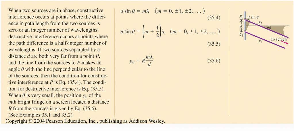
19 Thomas Young s experiment (1800) Light path difference between the rays arriving at y m : r 2 r 1 = d sinθ Condition for a bright fringe: r 2 r 1 = d sinθ = mλ; (m = 0,±1,±2,...) Condition for a dark fringe: r 2 r 1 = d sinθ = ( m + 1/ 2)λ; (m = 0,±1,±2,...) Position of a fringe on the screen: y m = R tanθ m tanθ m sinθ m for small angles or when d << R and then θ θ m y m = R tanθ m Rsinθ m Position of a bright fringe in Young's experiment: y m,bright = R mλ d ( Position of a bright fringe in Young's experiment: y m,dark = R m + 1/ 2 )λ d 19
20 Example In a Young s double slit experiment the slit width is 45 micron, the spacing between the slits is 0.2 mm, and the screen is located at m. Calculate position of the second order bright and dark fringe if wavelength of the light is 633 nm (red) (answer: y 2,bright,red =13 mm, y 2,dark,red =16 mm) If we change wavelength of the source to 532 nm (green), how the fringe spacing will change? (answer: y 2,bright,red =11 mm, y 2,dark,red =13 mm) Application: can we use a double slit to separate colors? 20
21 Applications of Interference in fields of science & engineering Chemistry / biology / Spectroscopy Biology / Biomedical engineering Mechanical Opto-mechanical Electronics / Optoelectronics / Electro-optics Material science engineering / Metrology Telecommunication / Military / Radar Aerospace / remote sensing / filter design Photography / Imaging / filtering 21
22 Targeted radio transmitter design An application of the interference Identical vertical dipole antennas oscillating at 1.5 MHz Pairs of antenna used to direct emitted energy in a particular direction Dark fringe area: bad reception Bright fringe area: good reception 22
23 Phasors: an alternative way of representing a wavefunction Each sinusoidal function is shown as a rotating vector or phasor whose projection on the x axis shows the instantaneous value of the function. Phasor s length represents the amplitude of the wave Phasor s angle with the positive x direction represents the phase of the wave (argument of the cosine function). Using phasors as a tool we can study superposition of the waves y y y E E E ωt E(t) = E cos(ωt) x ωt + φ E(t) = E cos(ωt + φ) x ωt + φ E(t) = E cos(ωt) + E cos(φ) x 23
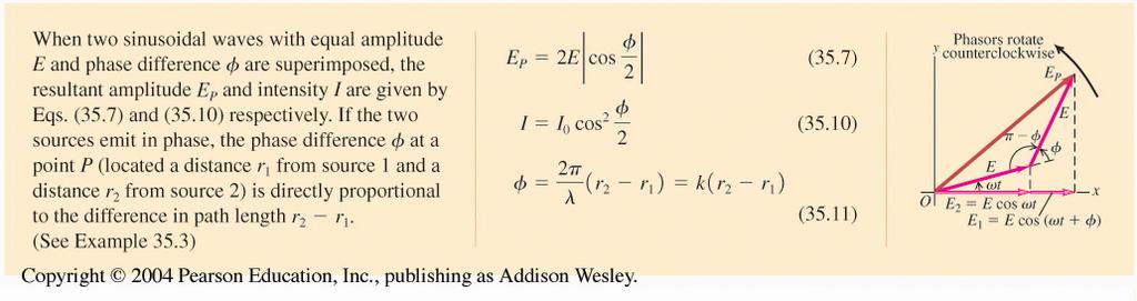
24 Intensity in interference patterns using Phasors E 1 (t) = E cos(ωt) E 2 (t) = E cos(ωt + φ) E p = E 1 + E 2 a vector sum of E 1 and E 2 Magntude of E p (from triangonomety) E p 2 = E 2 + E 2 2E 2 cos(π φ) E p 2 = E 2 + E 2 + 2E 2 cosφ = 2E 2 (1+ cosφ) Using 1+cosφ=2cos 2 (φ / 2) I E p 2 = 4E 2 cos 2 (φ / 2) Amplitude of two wave interference is independent of time: E p = 2E cos φ 2 depends only on the initial phase difference! 24
25 Intensity of interference patterns using superposition of two waves E p is Independent of time and frequency only depends on initial phase differences and amplitudes 25
26 Amplitude and phase difference E total = E p cos ωt + φ 2 = 2E cos φ 2 cos ωt + φ 2 When the initial phase difference is even integer of π : φ = 0, ± 2π ± 4π,...,±2mπ then the waves are in-pahse and resulting amplitude is maximum E p = 2E When the initial phase difference is an odd integer of π: φ = π,±3π,...,(2m + 1)π then the waves are out of pahse and resulting amplitude is E p = 0 Conclusion : superposition of two waves with same frequency and amplitude but different pahses yeild a wave with same frequency and an amplitude that varies between zero and twice the amplitude of the original waves. 0 E p 2E 26
27 Intensity in two source interference 27
28 Intensity distribution 28
29 Interaction of two waves What happens when two or more waves exist in one point of space? Based on what principle the waves interact? What is the result of interaction of two or more waves? What is the relationship of the interference pattern with the phases of the waves involved? 29
30 Young s double slit experiment Position of a bright fringe in Young's experiment: y m,bright = Rmλ / d Position of a dark fringe in Young's experiment: y m,dark = R m where (m = 0,±1,±2,...) Amplitude of the superimposed wave at point P: E total = E p cos ωt + φ 2 where E = 2E cos φ p 2 λ d Intensity in two source interference pattern: I = I 0 cos 2 φ 2 Where I 0 = 2ε 0 ce 2, and φ is the pahse difference between the waves arriving at point P from two sources. How to calculate the φ in a problem? 30
31 Intensity in two slit experiment 31
32 Phase, path & optical path Phase y = Asin ωt kx + φ ( ) At t = 0 phase constant or initial phase is = k wavenumber x Dis tan ce kx = 2π λ x = 2π x = 2π number of λs in the distance x λ Each λ is equivalent to 2π in phase. Oprical path = distance index of the environment OP = xn Optical path difference = path difference index OPD = Δxn = ΔOP or OPD = xδn + φ Phase phase difference = optical path difference wavenumber Δφ = Δxnk 32
33 Phase difference and path difference (problem geometry) 33
34 Example Use the relationship between phase and path difference to find the intensity of a double silt experiment as a function of path difference When the intensity is maximum? When it is minimum? Note: path difference is something we can measure in the lab easily. It is not so easy to measure phase difference. How we can measure phase difference between two waves? Answer: Work the problem

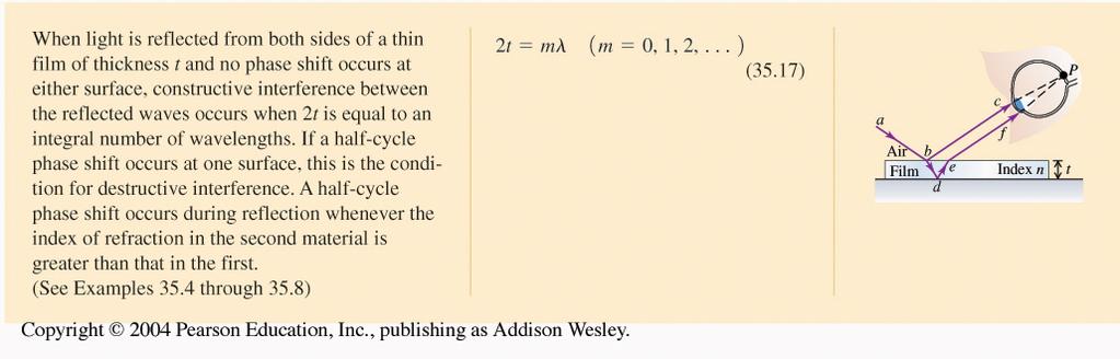
35 Interference in thin films Light rays reflected from two interfaces with path/ phase difference interfere. The condition for constructive interference is different for different wavelengths. As a result we see different colors at different angles 35
36 Interference at a wedge Path difference between two rays is almost equal to 2t (close to normal incidence) At the corner there is no path difference so we should see a bright fringe but experiment shows a dark fringe. What is the problem? 36
37 Reflected wave amplitude E r n a n b E i 37

38 Amplitude of reflected EM wave from an interface 38
39 Interference at a wedge Path difference between two rays is almost equal to 2t Wave 1 has zero phase shift due to reflection from the glass-air interface. Wave 2 has phase shift due to reflection from air-glass interface. That is why the left corner appears dark. Light path difference is zero but phase difference due to reflection is or half a cycle
40 General condition for constructive and destructive interference 40
41 Example: thin film interference Two microscope slides 10.0 cm long are in contact at one end and separate by a mm thick paper at the other end. What is the spacing of the interference fringes seen by reflection. Is the fringe at the line of contact a bright or dark one? Assume the slides are illuminated with monochromatic light with free space wavelength of 500 nm. (x m =mx1.25 mm) If n glass =1.52 and the gap is filled with water n water =1.33 what happens to the fringe spacing? (x=mx0.940mm) Now upper plate is a plastic n plastic =1.40, lower plate is a special glass with and n glass =1.6, and the gap is filled with silicon grease n grease =1.5. Is the fringe at contact point is a dark one or a bright one? 41

42 Non reflective or antireflection coatings (close to normal incidence) Conditions for antireflective coating: we have to have destructive interference between the rays 1 and 2: n coating <n glass t = λ / 4 The phase difference between rays 1 and 2 due to reflection is zero. Why? The phase difference due to path difference is Why? Total phase difference is so no light is reflected coating

43 Newton s rings; monochromatic source 43

44 Newton s rings with colored source 44
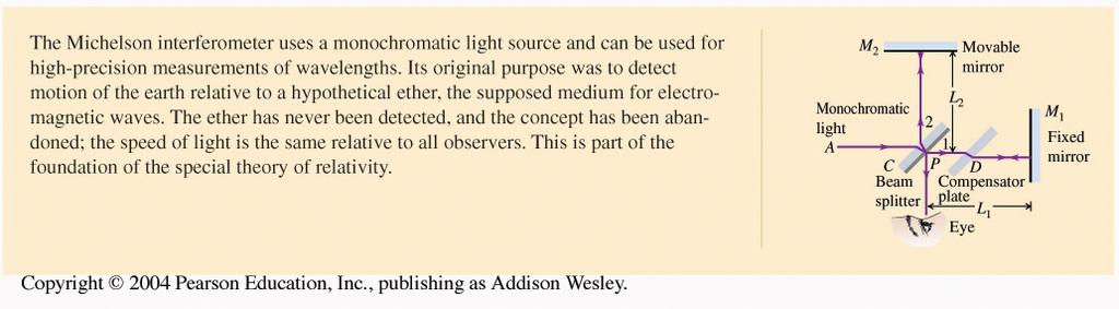
45 Michelson interferometer Historically has been developed to measure effect of the Ether on the speed of light By moving M 2 back and forth a distance of, λ / 2 the light path changes by amount. λ By moving M 2 back and forth a distance of y, m fringes pass by the crosshair of the eyepiece. y = m λ 2 m = 2y λ Nowadays it is used for measuring wavelength, index of refraction, glass inspection, stress analysis 45

46 Summary 46
47 47
Some properties of waves: Huygens principle Superposition Coherence Interference Young s double-slit experiment Thin-film interference
 Some properties of waves: Huygens principle Superposition Coherence Interference Young s double-slit experiment Thin-film interference Phys 2435: Chap. 35, Pg 1 Geometrical Optics Assumption: the dimensions
TA/TI survey. Phy Phy
 TA/TI survey https://webapps.pas.rochester.edu/secure/phpq/ Phy121 7 60 73 Phy123 1 6 11 Chapter 34 The Wave Nature of Light; Interference Units of Chapter 34 34-5 Interference in Thin Films 34-6 Michelson
Electricity & Optics
 Physics 24100 Electricity & Optics Lecture 26 Chapter 33 sec. 1-4 Fall 2017 Semester Professor Koltick Interference of Light Interference phenomena are a consequence of the wave-like nature of light Electric
PS210 - Optical Techniques. Section VI
 PS210 - Optical Techniques Section VI Section I Light as Waves, Rays and Photons Section II Geometrical Optics & Optical Instrumentation Section III Periodic and Non-Periodic (Aperiodic) Waves Section
WAVE OPTICS GENERAL. Fig.1a The electromagnetic spectrum
 WAVE OPTICS GENERAL - The ray optics cannot explain the results of the two following experimental situations: a) When passing by small openings or illuminating small obstacles, the light bends around borders
Double Slit is VERY IMPORTANT because it is evidence of waves. Only waves interfere like this.
 Double Slit is VERY IMPORTANT because it is evidence of waves. Only waves interfere like this. Superposition of Sinusoidal Waves Assume two waves are traveling in the same direction, with the same frequency,
The EYE. Physics 1502: Lecture 32 Today s Agenda. Lecture 4. Announcements: Optics. Midterm 2: graded after Thanks Giving
 Physics 1502: Lecture 32 Today s Agenda Announcements: Midterm 2: graded after Thanks Giving Homework 09: Friday December 4 Optics Eye interference The EYE ~f o objective I 2 L I 1 ~f e eyepiece 1 2 Compound
Light as a Transverse Wave.
 Waves and Superposition (Keating Chapter 21) The ray model for light (i.e. light travels in straight lines) can be used to explain a lot of phenomena (like basic object and image formation and even aberrations)
Intensity of Interference Patterns
 Intensity of Interference Patterns Wish to find I on a screen far away Let consider the E fields coming from the double slits: S 2 S 1 r r 2 1 E field from S 2 has a phase lag due to the extra path difference,
PH 222-3A Spring 2010
 PH -3A Spring 010 Interference Lecture 6-7 Chapter 35 (Halliday/Resnick/Walker, Fundamentals of Physics 8 th edition) 1 Chapter 35 Interference The concept of optical interference is critical to understanding
Chapter 35. Interference
 Chapter 35 Interference The concept of optical interference is critical to understanding many natural phenomena, ranging from color shifting in butterfly wings to intensity patterns formed by small apertures.
Chapter 10. Interference of Light
 Chapter 10. Interference of Light Last Lecture Wave equations Maxwell equations and EM waves Superposition of waves This Lecture Two-Beam Interference Young s Double Slit Experiment Virtual Sources Newton
C. Incorrect! The velocity of electromagnetic waves in a vacuum is the same, 3.14 x 10 8 m/s.
 AP Physics - Problem Drill 21: Physical Optics 1. Which of these statements is incorrect? Question 01 (A) Visible light is a small part of the electromagnetic spectrum. (B) An electromagnetic wave is a
LC circuit: Energy stored. This lecture reviews some but not all of the material that will be on the final exam that covers in Chapters
 Disclaimer: Chapter 29 Alternating-Current Circuits (1) This lecture reviews some but not all of the material that will be on the final exam that covers in Chapters 29-33. LC circuit: Energy stored LC
Michelson Interferometer
 Michelson Interferometer Objective Determination of the wave length of the light of the helium-neon laser by means of Michelson interferometer subsectionprinciple and Task Light is made to produce interference
A refl = R A inc, A trans = T A inc.
 Reading: Wave Optics 1, 2 Key concepts: Superposition; phase difference; amplitude and intensity; thin film interference; Fraunhofer diffraction; gratings; resolving power. 1.! Questions about interference
1. Waves and Particles 2. Interference of Waves 3. Wave Nature of Light
 1. Waves and Particles 2. Interference of Waves 3. Wave Nature of Light 1. Double-Slit Eperiment reading: Chapter 22 2. Single-Slit Diffraction reading: Chapter 22 3. Diffraction Grating reading: Chapter
Chapter 7. Interference of Light
 Chapter 7. Interference of Light Last Lecture Superposition of waves Laser This Lecture Two-Beam Interference Young s Double Slit Experiment Virtual Sources Newton s Rings Film Thickness Measurement by
Interference- Michelson Interferometer. Interference lecture by Dr. T.Vishwam
 Interference- Michelson Interferometer Interference lecture by Dr. T.Vishwam * Measurement of the coherence length of a spectral line * Measurement of thickness of thin transparent flakes * Measurement
Constructive vs. destructive interference; Coherent vs. incoherent interference
 Constructive vs. destructive interference; Coherent vs. incoherent interference Waves that combine in phase add up to relatively high irradiance. = Constructive interference (coherent) Waves that combine
Lecture PowerPoints. Chapter 24 Physics: Principles with Applications, 7 th edition Giancoli
 Lecture PowerPoints Chapter 24 Physics: Principles with Applications, 7 th edition Giancoli This work is protected by United States copyright laws and is provided solely for the use of instructors in teaching
Physics 142 Wave Optics 1 Page 1. Wave Optics 1. For every complex problem there is one solution that is simple, neat, and wrong. H.L.
 Physics 142 Wave Optics 1 Page 1 Wave Optics 1 For every complex problem there is one solution that is simple, neat, and wrong. H.L. Mencken Interference and diffraction of waves The essential characteristic
Engineering Physics 1 Prof. G.D. Varma Department of Physics Indian Institute of Technology-Roorkee
 Engineering Physics 1 Prof. G.D. Varma Department of Physics Indian Institute of Technology-Roorkee Module-03 Lecture-01 Interference of Light Part 01 Myself, Dr. JD Varma, Associate Professor in Department
Week 7: Interference
 Week 7: Interference Superposition: Till now we have mostly discusssed single waves. While discussing group velocity we did talk briefly about superposing more than one wave. We will now focus on superposition
Waves Part III Electromagnetic waves
 Waves Part III Electromagnetic waves Electromagnetic (light) waves Transverse waves Transport energy (and momentum) Can travel through vacuum (!) and certain solids, liquids and gases Do not transport
The maximum value of the acceleration occurs when sin=1 with magnitude
 SOLUTIONS 1231 T1 Q1. SHM Vibrating Strip (a)(i) For SHM, y = Asin(ωt + φ ) for amplitude A and angular frequency ω. Set φ = 0. (ii) The velocity is given by v = dy dx = ωa cosωt The maximum speed vm occurs
Phys 2310 Mon. Dec. 11, 2014 Today s Topics. Begin Chapter 9: Interference Reading for Next Time
 Phys 30 Mon. Dec., 04 Todays Topics Begin Chapter 9: nterference Reading for Next Time Reading this Week By Wed.: Begin Ch. 9 (9. 9.3) General Considerations, Conditions for nterference, Wavefront-splitting
Waves Part 3B: Interference
 Waves Part 3B: Interference Last modified: 31/01/2018 Contents Links Interference Path Difference & Interference Light Young s Double Slit Experiment What Sort of Wave is Light? Michelson-Morley Experiment
Waves Part 3: Superposition
 Waves Part 3: Superposition Last modified: 06/06/2017 Superposition Standing Waves Definition Standing Waves Summary Standing Waves on a String Standing Waves in a Pipe Standing Waves in a Pipe with One
Superposition of waves (review) PHYS 258 Fourier optics SJSU Spring 2010 Eradat
 PHYS 258 Fourier optics SJSU Spring 2010 Eradat") Superposition of waves (review PHYS 58 Fourier optics SJSU Spring Eradat Superposition of waves Superposition of waves is the common conceptual basis for some optical phenomena such as: Polarization Interference
Superposition of waves (review PHYS 58 Fourier optics SJSU Spring Eradat Superposition of waves Superposition of waves is the common conceptual basis for some optical phenomena such as: Polarization Interference
OPSE FINAL EXAM Fall 2016 YOU MUST SHOW YOUR WORK. ANSWERS THAT ARE NOT JUSTIFIED WILL BE GIVEN ZERO CREDIT.
 CLOSED BOOK. Equation Sheet is provided. YOU MUST SHOW YOUR WORK. ANSWERS THAT ARE NOT JUSTIFIED WILL BE GIVEN ZERO CREDIT. ALL NUMERICAL ANSERS MUST HAVE UNITS INDICATED. (Except dimensionless units like
Optics Interference from Films Newton s Rings Michelson Interferometer
 Optics Interference from Films Newton s Rings Michelson Interferometer Lana Sheridan De Anza College June 19, 2018 Last time diffraction patterns diffraction and interference resolution and Raleigh s criterion
[2] [2] Fig. 4.1
![[2] [2] Fig. 4.1](/thumbs/79/80000819.jpg "[2] [2] Fig. 4.1") 1 (a) (i) Explain what is meant by a progressive wave.... [2] (ii) State two differences between a progressive and a stationary wave. 1... 2... [2] (b) Fig. 4.1 shows, at time t = 0, the shape of a section
1 (a) (i) Explain what is meant by a progressive wave.... [2] (ii) State two differences between a progressive and a stationary wave. 1... 2... [2] (b) Fig. 4.1 shows, at time t = 0, the shape of a section
Optics. n n. sin c. sin
 Optics Geometrical optics (model) Light-ray: extremely thin parallel light beam Using this model, the explanation of several optical phenomena can be given as the solution of simple geometric problems.
INTERFERENCE 1.1 NATURE OF LIGHT
 1 INTERFERENCE 1.1 NATURE OF LIGHT In the year 1678, Christian Huygens proposed the wave theory of light. According to this, a Luminous body is a source of disturbance in hypothetical medium called ether
JRE Group of Institutions ASSIGNMENT # 1 Special Theory of Relativity
 ASSIGNMENT # 1 Special Theory of Relativity 1. What was the objective of conducting the Michelson-Morley experiment? Describe the experiment. How is the negative result of the experiment interpreted? 2.
Lecture 9: Introduction to Diffraction of Light
 Lecture 9: Introduction to Diffraction of Light Lecture aims to explain: 1. Diffraction of waves in everyday life and applications 2. Interference of two one dimensional electromagnetic waves 3. Typical
and the radiation from source 2 has the form. The vector r points from the origin to the point P. What will the net electric field be at point P?
 Physics 3 Interference and Interferometry Page 1 of 6 Interference Imagine that we have two or more waves that interact at a single point. At that point, we are concerned with the interaction of those
Lecture 2: Interference
 Lecture 2: Interference l S 1 d S 2 Lecture 2, p.1 Today Interference of sound waves Two-slit interference Lecture 2, p.2 Review: Wave Summary The formula y x,t Acos kx t describes a harmonic plane wave
Physics 116. Nov 3, Lecture 21 Wave optics. R. J. Wilkes 11/3/11 1
 Physics 116 Lecture 21 Wave optics Nov 3, 2011 R. J. Wilkes Email: ph116@u.washington.edu 11/3/11 1 Announcements 3 clickers have quiz data logged, but no registration: 622961 649314 614235 If one of these
SECTION A Waves and Sound
 AP Physics Multiple Choice Practice Waves and Optics SECTION A Waves and Sound 1. Which of the following statements about the speed of waves on a string are true? I. The speed depends on the tension in
Modern Physics. Luis A. Anchordoqui. Department of Physics and Astronomy Lehman College, City University of New York. Lesson III September 3, 2015
 Modern Physics Luis A. Anchordoqui Department of Physics and Astronomy Lehman College, City University of New York Lesson III September 3, 2015 L. A. Anchordoqui (CUNY) Modern Physics 9-17-2015 1 / 23
Physics General Physics II. Electricity, Magnetism and Optics Lecture 20 Chapter Wave Optics. Fall 2015 Semester Prof.
 Physics 21900 General Physics II Electricity, Magnetism and Optics Lecture 20 Chapter 23.1-2 Wave Optics Fall 2015 Semester Prof. Matthew Jones Announcement Exam #2 will be on Thursday, November 5 th (tomorrow)
 Name : Roll No. :.... Invigilator s Signature :.. CS/B.Tech (NEW)/SEM-2/PH-201/2013 2013 PHYSICS - I Time Allotted : 3 Hours Full Marks : 70 The figures in the margin indicate full marks. Candidates are
Lecture 11: Introduction to diffraction of light
 Lecture 11: Introduction to diffraction of light Diffraction of waves in everyday life and applications Diffraction in everyday life Diffraction in applications Spectroscopy: physics, chemistry, medicine,
sin constructive n same condition destructive 2 Interference Constructive - Destructive 2-slit single slit diff. grating
 Interference Constructive - Destructive 2-slit single slit diff. grating reflection Note: difference = 0 difference destructive 2 d sin reflection constructive d 2 sin tot. inter. = reflection + path length
Chapter 7 Interference of Light
 Chapter 7 Interference of Light Lecture Notes for Modern Optics based on Pedrotti & Pedrotti & Pedrotti Instructor: Nayer Eradat Spring 009 4/1/009 Interference of Light 1 Interference of light Interference
The Quantum Theory of Atoms and Molecules: Waves and Optics. Hilary Term Dr Grant Ritchie
 The Quantum Theory of Atoms and Molecules: Waves and Optics Hilary Term 008 Dr Grant Ritchie Wave motion - travelling waves Waves are collective bulk disturbances, whereby the motion at one position is
OPSE FINAL EXAM Fall 2015 YOU MUST SHOW YOUR WORK. ANSWERS THAT ARE NOT JUSTIFIED WILL BE GIVEN ZERO CREDIT.
 CLOSED BOOK. Equation Sheet is provided. YOU MUST SHOW YOUR WORK. ANSWERS THAT ARE NOT JUSTIFIED WILL BE GIVEN ZERO CREDIT. ALL NUMERICAL ANSERS MUST HAVE UNITS INDICATED. (Except dimensionless units like
Experiment O-2. The Michelson Interferometer
 Experiment O-2 The Michelson Interferometer The Michelson interferometer is one of the best known and historically important interferometers. It is a very accurate length-measuring device and has been
Larbert High School. Quanta and Waves. Homework Exercises ADVANCED HIGHER PHYSICS
 Larbert High School ADVANCED HIGHER PHYSICS Quanta and Waves Homework Exercises 3.1 3.6 3.1 Intro to Quantum Theory HW 1. (a) Explain what is meant by term black body. (1) (b) State two observations that
Electromagnetic Waves
 Electromagnetic Waves As the chart shows, the electromagnetic spectrum covers an extremely wide range of wavelengths and frequencies. Though the names indicate that these waves have a number of sources,
Quantum Interference and Duality
 Quantum Interference and Duality Kiyohide NOMURA Department of Physics December 21, 2016 1 / 49 Quantum Physics(Mechanics) Basic notion of Quantum Physics: Wave-Particle Duality Light (electromagnetic
Course: Physics 1. Module 3: Optics and Wave Phenomena
 MINISTRY OF EDUCATION AND TRAINING NONG LAM UNIVERSITY FACULTY OF FOOD SCIENCE AND TECHNOLOGY Course: Physics 1 Module 3: Optics and Wave Phenomena Instructor: Dr. Son Thanh Nguyen Academic year: 2008-2009
The science of light. P. Ewart
 The science of light P. Ewart Oxford Physics: Second Year, Optics Parallel reflecting surfaces t images source Extended source path difference xcos 2t=x Fringes localized at infinity Circular fringe constant
Homework Book. Wave Properties. Huijia Physics Homework Book 1 Semester 2. Name: Homeroom: Physics Class:
 Homework Book Wave Properties Huijia Physics Homework Book 1 Semester 2 Name: Homeroom: Physics Class: Week 1 Reflection, Refraction, wave equations 1. If the wavelength of an incident wave is 1.5cm and
Interferometers. PART 1: Michelson Interferometer The Michelson interferometer is one of the most useful of all optical instru
 Interferometers EP421 Lab Interferometers Introduction: Interferometers are the key to accurate distance measurement using optics. Historically, when mechanical measurements dominated, interferometers
Notes on Huygens Principle 2000 Lawrence Rees
 Notes on Huygens Principle 2000 Lawrence Rees In the 17 th Century, Christiaan Huygens (1629 1695) proposed what we now know as Huygens Principle. We often invoke Huygens Principle as one of the fundamental
Properties of waves. Question. Ch 22, : Waves & interference. Question. Phase difference & interference
 Exam Tue. Sep. 9, 5:30-7 pm, 45 Birge Covers.5-7,, 3.-4, 3.7, 4.-5, 6 + lecture, lab, discussion, HW Chap.5-7, Waves, interference, and diffraction Chap 3 Reflection, refraction, and image formation Chap
A 0.2 m s -1. B 10 m s -1. C 20 m s -1. D 40 m s -1
 Q1. Two points on a progressive wave are one-eighth of a wavelength apart. The distance between them is 0.5 m, and the frequency of the oscillation is 10 Hz. What is the minimum speed of the wave? 0.2
Maxwell s equations and EM waves. From previous Lecture Time dependent fields and Faraday s Law
 Maxwell s equations and EM waves This Lecture More on Motional EMF and Faraday s law Displacement currents Maxwell s equations EM Waves From previous Lecture Time dependent fields and Faraday s Law 1 Radar
Lecture 4: Diffraction & Spectroscopy
 Lecture 4: Diffraction & Spectroscopy d θ y L Spectra of atoms reveal the quantum nature of matter Take a plastic grating from the bin as you enter class. Lecture 4, p 1 Today s Topics Single-Slit Diffraction*
Lecture 28 March
 Lecture 28 March 30. 2016. Standing waves Musical instruments, guitars, pianos, organs Doppler Effect Resonance 3/30/2016 Physics 214 Spring 2016 1 Waves on a string If we shake the end of a rope we can
REVISION: WAVES, SOUND & LIGHT 11 JUNE 2013
 REVISION: WAVES, SOUND & LIGHT 11 JUNE 2013 Lesson Description In this lesson we revise: the Doppler Effect, Huygens Principle, Diffraction of Light & the Photoelectric Effect Key Concepts The Doppler
LECTURE 11 ELECTROMAGNETIC WAVES & POLARIZATION. Instructor: Kazumi Tolich
 LECTURE 11 ELECTROMAGNETIC WAVES & POLARIZATION Instructor: Kazumi Tolich Lecture 11 2 25.5 Electromagnetic waves Induced fields Properties of electromagnetic waves Polarization Energy of electromagnetic
Interference. Gambar: Museum Victoria Australia
 Interference Gambar: Museum Victoria Australia Formulation of Interference Intensity Superposition between two waves (point sources) Two separate point sources S 1 (x 1 ) and S 2 (x 2 ) generate EM waves
Physics 102: Lecture 20 Interference. Physics 102: Lecture 20, Slide 1
 Physics 102: Lecture 20 Interference Physics 102: Lecture 20, Slide 1 Phys 102 recent lectures Light as a wave Lecture 14 EM waves Lecture 15 Polarization Lecture 20 & 21 Interference & diffraction Light
Waves Review Checklist Pulses 5.1.1A Explain the relationship between the period of a pendulum and the factors involved in building one
 5.1.1 Oscillating Systems Waves Review Checklist 5.1.2 Pulses 5.1.1A Explain the relationship between the period of a pendulum and the factors involved in building one Four pendulums are built as shown
Measurements in Optics for Civil Engineers
 Measurements in Optics for Civil Engineers I. FOCAL LENGTH OF LENSES The behavior of simplest optical devices can be described by the method of geometrical optics. For convex or converging and concave
P5 Revision Questions
 P5 Revision Questions Part 2 Question 1 How can microwaves be used to communicate? Answer 1 Sent from transmitter, received and amplified by satellite in space, re-transmitted back to earth and picked
TOPIC: LIGHT, ELECTROMAGNETIC WAVES, 2D AND 3D WAVEFRONTS
 TOPIC: LIGHT, ELECTROMAGNETIC WAVES, 2D AND 3D WAVEFRONTS Learner Note: You need to know your definitions very well. You need to know the difference between refraction, reflection and diffraction. These
Chapter 15. Mechanical Waves
 Chapter 15 Mechanical Waves A wave is any disturbance from an equilibrium condition, which travels or propagates with time from one region of space to another. A harmonic wave is a periodic wave in which
Vågrörelselära och optik
 Vågrörelselära och optik Harmonic oscillation: Experiment Experiment to find a mathematical description of harmonic oscillation Kapitel 14 Harmonisk oscillator 1 2 Harmonic oscillation: Experiment Harmonic
INTERFERENCE OF LIGHT
 INTERFERENCE OF LIGHT Physics Without Fear Want to be good in Physics? Remember: PHYSICS IS AN ACTIVE SPORT Physics is like a sport. To be good in a sport, you must practice. Likewise, to be good in Physics
KEELE UNIVERSITY PHYSICS/ASTROPHYSICS MODULE PHY OSCILLATIONS AND WAVES PRACTICE EXAM
 KEELE UNIVERSITY PHYSICS/ASTROPHYSICS MODULE PHY-10012 OSCILLATIONS AND WAVES PRACTICE EXAM Candidates should attempt ALL of PARTS A and B, and TWO questions from PART C. PARTS A and B should be answered
Experiment 3 1. The Michelson Interferometer and the He- Ne Laser Physics 2150 Experiment No. 3 University of Colorado
 Experiment 3 1 Introduction The Michelson Interferometer and the He- Ne Laser Physics 2150 Experiment No. 3 University of Colorado The Michelson interferometer is one example of an optical interferometer.
Physics 4C. Chapter 35: Conceptual Questions: 2, 8, 12 Problems: 9, 21, 25, 26, 39, 40, 55, 72, 82, 83, 93
 Physics 4C Solutions to Chapter 35 HW Chapter 35: Conceptual Questions:, 8, 1 Problems: 9, 1, 5, 6, 39, 40, 55, 7, 8, 83, 93 Question 35- (a) increase (b) 1λ Question 35-8 (a) 300 nm (b) exactly out of
Lecture 15 Interference Chp. 35
 Lecture 15 Interference Chp. 35 Opening Demo Topics Interference is due to the wave nature of light Huygen s principle, Coherence Change in wavelength and phase change in a medium Interference from thin
MASSACHUSETTS INSTITUTE OF TECHNOLOGY Department of Physics Spring 2014 Practice Problem Set 11 Solutions
 MASSACHUSES INSIUE OF ECHNOLOGY Department of Physics 8 Spring 4 Practice Problem Set Solutions Problem : Electromagnetic Waves and the Poynting Vector We have been studying one particular class of electric
Re-radiation: Scattering. Electric fields are not blocked by matter: how can E decrease?
 Re-radiation: Scattering lectric fields are not blocked by matter: how can decrease? Cardboard Why there is no light going through a cardboard? lectric fields are not blocked by matter lectrons and nucleus
A beam of coherent monochromatic light from a distant galaxy is used in an optics experiment on Earth.
 Waves_P2 [152 marks] A beam of coherent monochromatic light from a distant galaxy is used in an optics experiment on Earth. The beam is incident normally on a double slit. The distance between the slits
Question 1. (Marks 16)
") 5 Question 1. (Marks 16) Consider the circuit shown in the figure, where C 1 = 6.00µF, C 2 = 3.00µF, and V = 20.0V. Capacitor C 1 is first charged by closing switch S 1. Switch S 1 is then opened, and
5 Question 1. (Marks 16) Consider the circuit shown in the figure, where C 1 = 6.00µF, C 2 = 3.00µF, and V = 20.0V. Capacitor C 1 is first charged by closing switch S 1. Switch S 1 is then opened, and
1/d o +1/d i =1/f. Chapter 24 Wave Optics. The Lens Equation. Diffraction Interference Polarization. The Nature of Light
 Chapter 24 Wave Optics Diffraction Interference Polarization 2F h o The Lens Equation 1/d o +1/d i =1/f F F O d o f d i h i Geometrical and Physical Optics Geometrical Optics: The study of optical phenomena
Name Class Date. What two models do scientists use to describe light? What is the electromagnetic spectrum? How can electromagnetic waves be used?
 CHAPTER 16 12 SECTION Sound and Light The Nature of Light KEY IDEAS As you read this section, keep these questions in mind: What two models do scientists use to describe light? What is the electromagnetic
Physics 280 Week 04 In-Class Problems Summer 2016
 Physics 80 Week 04 In-Class Problems Summer 016 1. Consider the interface of water with class (say at the bottom of a beaker filled with water). Given: The index of refraction for water is n w = 1.33 and
Final Exam is coming!
 Final Exam is coming! Thurs., May 4, 4:30 to 6:30 pm, in this room. 25 multiple-choice questions Personalized exams I will enter the grade on your Mastering Physics account ( Final ). Old Part is comprehensive.
Experiment 6: Interferometers
 Experiment 6: Interferometers Nate Saffold nas2173@columbia.edu Office Hour: Mondays, 5:30PM-6:30PM @ Pupin 1216 INTRO TO EXPERIMENTAL PHYS-LAB 1493/1494/2699 NOTE: No labs and no lecture next week! Outline
LECTURE 32: Young's Double-Slit Experiment
 Select LEARNING OBJECTIVES: LECTURE 32: Young's Double-Slit Experiment Understand the two models of light; wave model and particle model. Be able to understand the difference between diffraction and interference.
Profs. Y. Takano, P. Avery, S. Hershfield. Final Exam Solution
 PHY2049 Fall 2008 Profs. Y. Takano, P. Avery, S. Hershfield Final Exam Solution Note that each problem has three versions, each with different numbers and answers (separated by ). The numbers for each
Topic 4: Waves 4.3 Wave characteristics
 Guidance: Students will be expected to calculate the resultant of two waves or pulses both graphically and algebraically Methods of polarization will be restricted to the use of polarizing filters and
Introduction to Optics
 Introduction to Optics The Pasco Optics System. Figure 1 (Courtesy of PSCO) Setting up the Equipment The Optics Bench The optics bench is shown in Fig. 2 along with the light source, component holder and
Chapter 33. Electromagnetic Waves
 Chapter 33 Electromagnetic Waves Today s information age is based almost entirely on the physics of electromagnetic waves. The connection between electric and magnetic fields to produce light is own of
B.Tech. First Semester Examination Physics-1 (PHY-101F)
") B.Tech. First Semester Examination Physics-1 (PHY-101F) Note : Attempt FIVE questions in all taking least two questions from each Part. All questions carry equal marks Part-A Q. 1. (a) What are Newton's
B.Tech. First Semester Examination Physics-1 (PHY-101F) Note : Attempt FIVE questions in all taking least two questions from each Part. All questions carry equal marks Part-A Q. 1. (a) What are Newton's
Michelson Interferometer. crucial role in Einstein s development of the Special Theory of Relativity.
 Michelson Interferometer The interferometer Michelson experiment Interferometer of Michelson and Morley played 0 a crucial role in Einstein s development of the Special Theory of Relativity. Michelson
1. A wave front is a surface of constant: A. phase B. frequency C. wavelength D. amplitude E. speed ans: A
 Chapter 35: INTERFERENCE 1 A wave front is a surface of constant: A phase B frequency C wavelength D amplitude E speed 2 Huygens construction can be used only: A for light B for an electromagnetic wave
CHAPTER 10. Knowledge
 CHAPTER 10 Review K/U Knowledge/Understanding T/I Thinking/Investigation C Communication A Application Knowledge For each question, select the best answer from the four alternatives. 1. A light wave travels
Physics 30: Chapter 5 Exam Wave Nature of Light
 Physics 30: Chapter 5 Exam Wave Nature of Light Name: Date: Mark: /33 Numeric Response. Place your answers to the numeric response questions, with units, in the blanks at the side of the page. (1 mark
34. Even more Interference Effects
 34. Even more Interference Effects The Fabry-Perot interferometer Thin-film interference Anti-reflection coatings Single- and multi-layer Advanced topic: Photonic crystals Natural and artificial periodic
CHAPTER 6 INTRODUCTION TO SPECTROPHOTOMETRIC METHODS Interaction of Radiation With Matter
 CHAPTER 6 INTRODUCTION TO SPECTROPHOTOMETRIC METHODS Interaction of Radiation With Matter 1 Announcements Add to your notes of Chapter 1 Analytical sensitivity γ=m/s s Homework Problems 1-9, 1-10 Challenge
CHAPTER 6 INTRODUCTION TO SPECTROPHOTOMETRIC METHODS Interaction of Radiation With Matter
 CHAPTER 6 INTRODUCTION TO SPECTROPHOTOMETRIC METHODS Interaction of Radiation With Matter Announcements Add to your notes of Chapter 1 Analytical sensitivity γ=m/s s Homework Problems 1-9, 1-10 Challenge