Design and Testing of 1 kw Hall Thruster
|
|
|
- Avice Page
- 6 years ago
- Views:
Transcription
1 Design and Testing of 1 kw Hall Thruster Nicholas Ian Denning, Nicholas Alfred Riedel Colorado State University Advised by: Dr. Binyamin Rubin, Dr. John Williams ndenning@engr.colostate.edu, nriedel@engr.colostate.edu 7 April 2008 Abstract During the last decade there has been an increased interest in the use of electric propulsion on spacecraft. The high specific impulse of electric propulsion devices enables one to increase the payload mass, life span of spacecraft, or perform complex orbital maneuvers with a minimum amount of propellant. The Hall thruster, one of many electric propulsion devices, has become the most widely used form of electric propulsion due to its high performance and relative simplicity. Hall thrusters are currently used in various space applications including satellite orbit correction and station keeping. A noncontact measurement method was proposed by Rubin, Geulman, and Kapulkin, , enabling real-time thrust estimation, which is currently not possible to do on conventional Hall thrusters. The proposed method uses several miniature magnetic field sensors embedded inside the Hall thruster. These sensors will monitor the magnetic field produced by the plasma current loop in the thruster acceleration channel. Information on magnetic field measurements from the sensors will be used to determine Hall current distribution inside the thruster and to estimate thrust. The sensor data is also useful for thruster design optimization. The Hall thruster that was designed, manufactured, and tested to validate the concept, is described in this paper. This thruster, intended for operation at 1 kilowatt power level, was designed to be easily assembled and disassembled to allow access to the magnetic sensors placed inside. The results of magnetic field and thermal modeling obtained during thruster design, and later validated experimentally, are discussed. The results of the thruster firing tests are also presented. I. Introduction Although the idea of electric propulsion was introduced around the turn of the century, serious research didn t begin in the United States and Russia until the late 1950 s. It wasn t until 1990 however that this technology was developed enough to be used on modern spacecraft. 2 Electric propulsion has become increasingly popular and studied more in depth in the past decade. Although it does not provide thrust levels as high as chemical propulsion, it can prove advantageous for missions where low thrust is not a limiting factor and longer mission duration can be tolerated. The high specific impulse provided by electric propulsion allows spacecraft to travel farther and faster than a similar spacecraft using chemical thrusters. The drawback is that electrical propulsion requires operating the thruster for a longer period of time before the top speed is reached. Electric propulsion systems can also provide a less expensive alternative to the use of chemical thrusters. Currently electric propulsion is used for station keeping, orbit adjustments, and provides the primary source of propulsion for many deep space missions. Conventional ion thrusters are operated by applying an electric potential between two grids. Gas is then ionized and the ions are accelerated through the grids producing thrust. The biggest drawback of this form of electric propulsion is that the thruster is space charge limited, thus restricting the ion current density as well as the thrust. Hall Effect thrusters are alternative types of ion thrusters which provide higher thrust density. The main advantage is that they involve the formation of quasi-neutral plasma and therefore ion current is not limited by space charge. The induced magnetic field in Hall thrusters is used to slow the flow of electrons to the anode and creates a halo of circulating electrons in the discharge chamber. This allows for a more efficient ionization than conventional ion thrusters provide. Hall thrusters operate at high specific impulses (greater than 1500 seconds), moderate thrust levels (100 to 200 mn), and efficiencies Denning 1

2 greater than 50% in the 1 to 10 kw range. 3 Due to these characteristics, they are well suited for many varieties of space mission applications. Hall thruster operation is accomplished by applying a large electrical potential difference between the anode and a cathode as is observed in Figure 1. Small mass flow rates of propellant, usually xenon gas, are fed through both. This creates plasma and allows electrons to flow into the discharge chamber towards the anode. Electromagnetic coils placed in the center and around the perimeter of the thruster are charged and a magnetic field is induced trapping electrons in the discharge chamber. The propellant is continuously fed through the anode into the discharge chamber where collisions occur between the gas and the trapped electrons causing the propellant atoms to ionize. Ions are then accelerated by the electric field and emitted from the discharge chamber. These ions exit at a high velocity when emitted and therefore produce thrust. Once out of the thruster, ions are then neutralized by the flow of electrons from the cathode creating a discharge plume with no net charge. Currently, there is no method for measurement of thrust in real time when a Hall thruster is in operation on a spacecraft. A noncontact measurement method was proposed which uses several Figure 1 - Hall Thruster Operation small magnetic sensors to monitor the magnetic field induced by (Courtesy of the azimuthal plasma current. 1 In order to validate this theory, a low cost Hall thruster was needed for testing. While this thruster was produced, two separate teams worked on the various components to be used for validation. One team concentrated on the sensor arrays that would be embedded in the thruster. The other team fabricated a thrust stand that enabled thrust measurement and efficiency calculation of the thruster. Careful attention was paid to the thermal characteristics of the thruster so the sensors would not be exposed to higher than allowable temperatures. The thruster designed was to operate at approximately 1 kw power and was to be easily modified for sensor placement. Dimensioning II. Thruster Design The Hall thruster described here is Stationary Plasma Thruster (SPT) type. The main feature of this type is that discharge chamber walls are made of insulating material. Through intensive research of existing Hall thruster documentation, it was decided to use the sizing convention presented at an electric propulsion seminar given at the Massachusetts Institute of Technology in 1991 by Russian Hall thruster designers and published in Gulczinski s doctoral dissertation at the University of Michigan. 2 It was found b m =.3d ch [mm] b ch = b m [mm] L c =.32b m [mm] L a = 2L c [mm] L ch 1.1L a [mm] Figure 2 - Sizing for Hall Thruster 2 Denning 2


3 that there exists a relationship between certain dimensions on a Hall thruster which give a maximum efficiency. This relationship is explained using the equations and corresponding picture in Figure 2. The Russian designed SPT100 runs at approximately 1 kw of power and has a discharge chamber diameter of 100 mm. Taking this as the discharge chamber diameter and using the relationships given above, sizing of the thruster was computed. The calculations and final dimensioning can be found in Appendix A. Discharge Chamber One of the most important parts of a Hall thruster is the discharge chamber, which is generally made of Boron Nitride or another type of ceramic. This is because ceramics provide a higher sputtering resistance than metals or polymers. Aluminum Oxide (alumina) was chosen due to the fact that it was widely available and cost effective. Most Hall thrusters use a discharge chamber machined from a solid block of ceramic; however, it was decided to use a design in which multiple alumina plates were machined separately and stacked on top of each other for the final assembly. Like many ceramics, alumina is notoriously brittle. For this reason, the bottom plates were increased in thickness in the radial direction in an effort to prevent cracking and improve the structural integrity of the discharge chamber. The thickness of the top two plates could not be increased as the pole pieces limited the available space. The multiple plate design was chosen due to the fact that it was easier to machine, more accommodating to sensor placement, and individual broken pieces would be easier to replace. Multiple plates may also provide further research opportunities not possible with a single unit. The drawback of this design was that it required the use of compression plates to hold the machined alumina plates in place and prevent them from shifting in the thruster assembly. To properly align the alumina plates, they were Super-Glued into the correct positions, allowing the discharge chamber to be installed as a unit before compression plates were attached. Once the thruster reaches a moderate operating temperature, the Super-Glue burns out and only the Figure 3 - Thruster Compression Plates compression plates hold the alumina in place. In order not to interfere with the magnetics of the thruster, the compression plates were made from a non-magnetic stainless steel. A Pro-Engineer model of the thruster and how the plates integrate can be seen in Figure 3. This design will also help reduce sputtering of the magnetic pole pieces. If the compression plates themselves become too eroded, they can quickly and easily be replaced. Thruster Design: Anode The dimension from the top of the anode to the top of the discharge chamber (L ch ) and the dimension from the top of the anode to the top of the discharge chamber (L a ) both play a large role in determining the efficiency of the thruster. Slight variations in these values allow for fine tuning of the maximum thruster output. For this reason, space has been left below the discharge chamber and below the anode in order to insert stainless steel spacers. The spacers, observed in Figure 4, can be varied in height allowing the thruster output to be adjusted to achieve the maximum efficiency and therefore the optimal power output. The anode was machined out of non-magnetic stainless steel so it would not affect the magnetic field. Eighteen evenly spaced holes,.016 in diameter, were placed to allow propellant to flow into the discharge chamber. The hole size and quantity were chosen so that the sum of the area of the discharge holes was less than the area of the inlet gas line. This promotes a uniform discharge flow. Once dimensions for the thruster were achieved a Pro-Engineer model Figure 4 - Anode Spacers was generated, a cross section of which can be seen in Figure 5. Denning 3


4 Figure 5 - Cross Section of Thruster Design III. Preliminary Analysis Magnetic Analysis Although much of the thruster dimensioning had been determined by the equations presented above, there was still a great deal of work to be done with the overall magnetic field. In order to achieve the greatest thruster efficiency, it was ideal to have the magnetic field focused between the pole pieces, with the area of the discharge chamber as magnetically neutral as possible. To achieve these properties, thin rings of magnetic steel were placed between the discharge chamber and the coils. These magnetic shields are common in most Hall thrusters. Since the thruster was designed for interchangeability and variability, it was necessary for the magnetic shields to be removable. Instead of welding the shields into place, as was originally purposed, it was decided they could be bolted onto the thruster base plate. To allow room to drill and tap, the steel thickness was set at.125. This left only the height of the shield to be determined. The shield height has a dramatic effect not only on the magnetic fields in the discharge chamber, but also the strength of the field between the pole pieces. If the shield is too tall and placed too close to a pole piece, much of the magnetic flux created by the coils is drawn to the shield and not transmitted between the two poles as desired. Conversely, if the shields are too short, the magnetic field between the pole pieces is stronger but there is more magnetic interference in the discharge chamber. To determine the proper shield height, a number of tests were conducted using the two-dimensional magnetic modeler Finite Element Method Magnetics (FEMM). The height of the shield began at 1.25 and increased by.0625 increments to To simulate the load applied to the thruster, the center core was modeled to have 300 coils of wire with a load of 2 Amps and each of the outer cores had 150 coils with a load of 1 Amp. (It was necessary to run more current through the center coil to produce a more symmetric magnetic field). The simulations were run for each height and the resulting magnetic fields were mapped. Plots of magnetic field intensity through the center of the discharge chamber were also constructed. Using the results in Appendix B, comparisons were then made and the screen height that provided the greatest balance of characteristics ( ) was selected. Figure 6-3D Magnetic Magnitudes Denning 4

5 With a screen height chosen, the next step was to verify the 2D results with a 3D analysis. The entire magnetic system of the thruster was modeled using the analysis program Maxwell 3D. The same loads applied to the coils in the 2D analysis were applied to the 3D model. The resulting magnitude plot (Figure 6) and vector field (Figure 7) were then compared to the fields and magnitudes previously estimated. It turned out that both the magnitude and field shapes predicted by the FEMM program were almost identical to the results of the Maxwell analysis. It was concluded that the data gathered from the 2D analysis was valid, and would provide an accurate prediction of the magnetic characteristics. Figure 7-3D Magnetic Vector Field Thermal Analysis The next issue for consideration was the thermal characteristics of the thruster. In most Hall Effect thrusters, temperatures can easily exceed 400 C. Since the sensors to be placed inside the thruster have a temperature limit of 300 C it was necessary to get an approximation for the temperatures that would be experienced during operation. Researchers in France have observed a maximum temperature in a similar 1kW thruster at approximately 600 C 4. In these thrusters, the anode acts as the primary source of heat; the thermal addition from the coils is negligible. Using this information, the thruster was modeled using the program ephysics. To generate a conservative model, the anode was set to a constant temperature of 800 C while the rest of the thruster began at 30 C. The material properties of the model were set to match the materials to be used on the actual thruster. A vacuum condition was also modeled to allow conduction and radiation as the only modes of heat transfer. This simulation provided results that were similar to findings observed with actual thrusters at other institutions. The maximum temperature at the anode was very conservative, around 750 C. Most of the thruster was a little above 150 C. These results, shown in Figure 8, served as a general model until actual temperatures were measured when the thruster was operational. Figure 8 - Thermal Analysis Results Denning 5
6 IV. Equipment Although the general concepts behind the operation of a Hall thruster are relatively simple, there is a large amount of hardware required for testing. All testing must be performed in a high vacuum environment, with enough space and a high enough pumping speed such that the gas emitted in the discharge plume doesn t have a chance to return to the thruster for re-ionization. For this reason a steel vacuum chamber, 5 feet in diameter and 15 feet in length, was used for the tests. To pump the chamber down from atmospheric pressure, an Edwards GV250 dry mechanical pump was used, which was later assisted by an Edwards EH-1200 mechanical booster pump when the pressure reached 30 Torr. When the chamber pressure reached 20 mtorr with only the mechanical pumps running, two Varian HS-20 diffusion pumps were turned on. This allowed the chamber to reach a baseline pressure in the high 10-6 Torr range. An argon high pressure cylinder was connected to a network of stainless steel gas lines and used to supply fuel to the anode and cathode, as pictured in Figure 9. The purity of the argon was %. Flow of the gas was regulated using two Brooks 5850E mass flow controllers; the anode controller rated for 200 sccm argon and the cathode controller rated for 50 sccm argon. The mass flow Figure 9 - Fuel Supply Schematic controllers were powered and managed using two Brooks 5896 power supplies. Power was provided to all the separate components through a number of power supplies. The cathode heater used a Sorensen DCS40-25E, while the keeper was powered by a Spellman SL A Gold Tool DPS-5050 power supply provided the current for the inner coil, and a TDK-Lambda ZUP10-20 powered the outer coils. The supply used for the main discharge was a custom built unit, capable of 600V/15A output. A wiring schematic is provided in Figure 10. Figure 10 - Wiring Diagram Test information was collected using a HP/Agilent 34970A data acquisition unit, and was sent to a PC equipped with LabVIEW. The LabVIEW program was used to send the data to an Excel file to allow for easy processing. The data recorded through this system included chamber pressure, anode fuel flow rate, cathode fuel flow rate, discharge voltage, inner magnet voltage, outer magnet voltage, and readings from 5 thermocouples. The final thruster design resulted in an overall diameter of 8 inches, with a height of approximately 2 inches. The inner core was wrapped with 22 gauge magnet wire allowing for 850±45 turns, while each outer core was wrapped with 18 gauge magnet wire allowing for 200±10 turns. The overall weight of the Denning 6


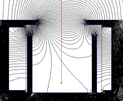
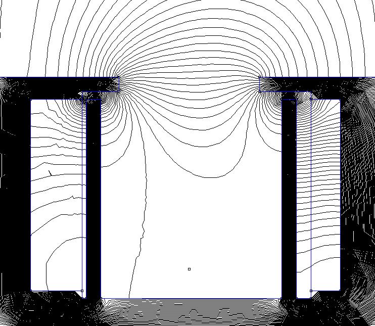
7 thruster was about 12 pounds. The pole pieces and base plate were cut from ASTM A36 steel, while the cores and shields were constructed from AISI 1018 steel. The anode and compression plates were machined from stainless steel. Figure 11and Figure 12 display the final assembly of the thruster. A hollow cathode with a porous tungsten insert impregnated with low work function material was used to provide electrons both for discharge and for plume neutralization. Figure 11 - Rear of Thruster Figure 12 - Thruster Assembly V. Testing and Results Magnetic Mapping Once the design and manufacture of the thruster was finished, it was possible to begin testing. Before the thruster was fired in the vacuum, a mapping of the magnetic fields was completed. This was done using a 2-axis linear actuation system and a Gauss-meter. Since the alumina discharge chamber, anode, and compression plates were made of non-magnetic materials, they were not installed on the thruster. This allowed the magnetic probe to take readings in a wider range of locations and permitted a broader understanding of the fields produced. The readings were taken in the axial direction at 1 mm increments; from the base plate to 10 cm away. This was done at 5 different radial locations between the inner and outer pole pieces. A LabVIEW program collected the probe positions and magnetic field strengths and wrote the data to an Excel file. With a desired power output of 1 kw, the ideal field strength would be 150 Gauss at the center of the acceleration channel between the pole pieces. After further computer simulations were performed knowing the actual number of turns in the coils, it was determined that this optimal performance would be achieved with 1 Amp of current to the inner coil and 2 Amps to the outer coils. The models showed that this excitation would provide the same field shapes seen in the preliminary analysis, with the correct field strength. Using this information, the thruster magnetic system was mapped. The data gathered from mapping was used to plot the magnetic field lines and intensities, shown in Figure 13. It was observed that the actual field strength was about 35 Gauss less than computer simulations predicted. Efforts were made to increase the strength of the magnetic field by varying the current provided to the coils. The results of these trials can be seen in Figure 14. Magnetic field lines and intensities for each case of current variation can be found in Appendix C. Since the field strength was relatively unresponsive when the current was increased, it was believed that the center core was reaching magnetic saturation. Denning 7 Figure 13 - Magnetic Field Lines and Intensities. The Black U-Shape Indicates the Walls of the Discharge Chamber. (Inner Coil: 1A, Outer Coil: 2A)


8 Simulations in Maxwell 3D showed the core was close to saturation, though not reaching it. However, the computer model uses an ideal B-H curve for the steel. Magnetic properties can vary greatly even in similar metals, thus it is likely that the actual B-H curve yields a lower saturation point for this particular sample. Although the magnetic field was lower than desired, it was decided that the thruster would still be able to operate. The decreased magnetic peak would only lead to a slight drop in efficiency inner coil - 0.5A, outer coil - 1 A inner coil - 0.5A, outer coil - 2 A inner coil -1A, outer coil - 1 A inner coil - 1A, outer coil - 2 A inner coil - 1A, outer coil - 3 A inner coil - 1.5A, outer coil - 2 A inner coil - 1.5A, outer coil - 3 A Br, gauss 60 Anode location Exit plane Axial coordinate,cm Figure 14 - Changes in Field Strength Corresponding to Changes in Applied Current Testing in Vacuum Once the magnetic mapping was complete, the entire thruster was assembled and placed into the vacuum chamber. Electric and fuel lines were connected as previously described and the chamber was pumped down. When the chamber had reached its baseline pressure, the cathode heater was turned on along with the cathode gas flow. As soon as the cathode finished conditioning, the heater was turned off and the keeper was turned on. The gas supply to the anode was activated and a large electric potential was applied to the anode. This resulted in the start of the thruster. When the discharge had stabilized, power was provided to the coils and the thruster was completely operational. The operational thruster can be seen in Figure 15 and Figure 16. Figure 15 - Side View of Thruster Operation Figure 16 - Front View of Thruster Operation Denning 8
9 Table 1 provides data from the modes tested. It is believed that higher power levels will be reached as testing continues. Cathode Flow Rate (sccm) Anode Flow Rate (sccm) Table 1 - Modes of Thruster Operation Discharge Voltage (V) Dicharge Current (A) Discharge Power (W) Thermal The thruster was active in vacuum for a period of approximately three hours. It demonstrated stable operation in a range of modes as described in Table 1. Thermocouples were placed at 4 separate locations on the thruster and 1 location on the stand in order to monitor temperatures. Figure 17 shows a plot of each temperature during the operation of the thruster. Due to manipulation of flow rates and voltages, the thruster experienced unstable modes twice during operations (after approximately 1 hour and then again after 3 hours). During these times the thruster was inactive for a short period of time and a drop in temperatures resulted. Although steady state was not reached, it can be approximated from the trends that no temperature measured will exceed approximately 180 C. The coil temperatures should not be greater than 150 C, which is well below the maximum operating temperature of the magnet wire (200 C). These readings correspond well to the preliminary thermal analysis, though more data will be gathered before final placements of sensors are determined. Figure 17 - Plot of Thruster Temperatures Denning 9
10 VI. Difficulties Encountered Some minor difficulties arose during vacuum testing of the thruster. On the first testing attempt, plasma was formed behind the thruster and electrical arcing occurred. This prevented the stabilization of discharge and therefore inhibited continual thruster operation. After a brief investigation, it was found that a gas line fitting was leaking and allowed the formation of plasma behind the thruster. The faulty o-ring was replaced and all exposed gas line was wrapped with Teflon tape to prevent arcing. Another problem was encountered when an attempt was made to restart the thruster after operation for extended periods of time. After troubleshooting the situation, it was concluded that the magnetic remanence in the cores and pole pieces prevented the flow of electrons from the cathode to the anode, thus preventing restart of the thruster. To remedy the problem a procedure was implemented in which the leads of the coils were reversed on the power supplies and a very low current was provided for a short period of time in order to induce an opposing magnetic field. This canceled out the remnant magnetic field and allowed for successful start up of the thruster. VII. Future With the successful test of the thruster, the design proved to be functional. To improve the magnetic field strength, a replacement core will be machined with a larger diameter center. This increased area should bring the steel away from its saturation point and allow a greater magnetic flux. Adjustments to anode and exit plane height will be made in efforts to improve efficiency. Further tests will also be conducted in order to obtain current-voltage curves. With these tests finished, an optimal operating condition will be found. Thermal characteristics will continue to be investigated until steady-state temperatures are verified and a more complete thermal model can be made. Sensors will then be integrated into the thruster in order to measure the magnetic fields induced by the Hall current. Measurements taken by the thrust stand will be incorporated and in turn validate that the non-intrusive thrust measurement is possible. VIII. References 1. B.Rubin, M.Guelman, and A.Kapulkin, Magnetic Sensing of Azimuthal Current in Hall Thruster: In- Flight Diagnostic Potential, Journal of Propulsion and Power, 2008 vol.24 no.1, p F.S.Gulczinski III, Examination of the Structure and Evolution of Ion Energy Properties of a 5 kw Class Laboratory Hall Effect Thruster at Various Operational Conditions, University of Michigan Doctoral Dissertation, N.Gascon, W.Scott Crawford, R.L.Corey, M.A. Cappelli, Coaxial Hall Thruster with Diamond Inner Channel Wall, 42 nd AIAA Joint Propulsion Conference & Exhibit, S.Mazouffre, P.Echegut, M. Dudeck, A Calibrated Infrared Imaging Study on the Steady State Thermal Behavior of Hall Effect Thrusters, Plasma Sources Science and Technology, 2007 vol.16, p Denning 10
11 APPENDIX A Sample Thruster Calculations The dimensions for the thruster were determined using the following equations. Knowing that a discharge chamber diameter of 100 mm would yield approximately a 1 kw power output, the other dimensions were calculated as seen below: d ch := 100 b m :=.3 d ch b m = 30 b ch := b m b ch = L c :=.32 b m L c = 9.6 L a := 2 L c L a = 19.2 L ch := 1.1 L a L ch = Due to the fact that the above equations are used to find the dimensions in millimeters, the values were converted to inches to keep consistent tooling on the project. When converted to English units the values were corrected slightly to allow for more rounded dimensions to aid in machining. A summary of these values can be seen in Table A1 below. Thruster Dimension Table A1 - Thruster Dimensions [mm] [inch] [inch] (corrected) dch bm Lc La Lch Denning 11


12 APPENDIX B - Finite Element Method Magnetics (FEMM) Results The following are the plots from the FEMM analysis used to determine the proper shield height. The plots on the left show the strength of the magnetic field down the center of the discharge chamber. The figures on the right show the resulting magnetic field lines. Using these results, a shield height of was chosen, as it displayed the best combination of properties. Shield Height: 1.25 Shield Height: Denning 12


13 Shield Height: Shield Height: Shield Height: 1.5 Denning 13


14 Shield Height: Shield Height: Shield Height: Denning 14

15 Appendix C Magnetic Field Mapping Results The following are plots of magnetic field lines and intensities for all cases of current variations tested. The black U-shape represents the walls of the discharge chamber of the thruster in reference to fields. Inner coil 1A, Outer coil 2 A Inner coil 1A, Outer coil 1 A Inner coil 1A, Outer coil 3 A Denning 15

16 Inner coil 0.5A, Outer coil 1 A Inner coil 0.5A, Outer coil 2 A Inner coil 1.5A, Outer coil 2 A Denning 16
17 Inner coil 1.5A, Outer coil 3 A Denning 17
Figure 1, Schematic Illustrating the Physics of Operation of a Single-Stage Hall 4
 A Proposal to Develop a Double-Stage Hall Thruster for Increased Efficiencies at Low Specific-Impulses Peter Y. Peterson Plasmadynamics and Electric Propulsion Laboratory (PEPL) Aerospace Engineering The
Development of stationary plasma thruster SPT-230 with discharge power of kw
 Development of stationary plasma thruster SPT-230 with discharge power of 10...15 kw IEPC-2017-548 Presented at the 35th International Electric Propulsion Conference Georgia Institute of Technology Atlanta,
Development of a Two-axis Dual Pendulum Thrust Stand for Thrust Vector Measurement of Hall Thrusters
 Development of a Two-axis Dual Pendulum Thrust Stand for Thrust Vector Measurement of Hall Thrusters Naoki Nagao, Shigeru Yokota, Kimiya Komurasaki, and Yoshihiro Arakawa The University of Tokyo, Tokyo,
Abstract. Objectives. Theory
 A Proposal to Develop a Two-Stage Gridless Ion Thruster with Closed Electron Drift Richard R. Hofer Plasmadynamics and Electric Propulsion Laboratory (PEPL) Department of Aerospace Engineering University
High-impulse SPT-100D thruster with discharge power of kw
 High-impulse SPT-D thruster with discharge power of 1.0 3.0 kw IEPC-2017-40 Presented at the 35th International Electric Propulsion Conference Georgia Institute of Technology Atlanta, Georgia USA R. Gnizdor
OPERATION PECULIARITIES OF HALL THRUSTER WITH POWER kw AT HIGH DISCHARGE VOLTAGES
 OPERATION PECULIARITIES OF HALL THRUSTER WITH POWER 1.5 2.0 kw AT HIGH DISCHARGE VOLTAGES M.B. Belikov, N.V. Blinov, O.A. Gorshkov, R.N. Rizakhanov, A.A. Shagayda Keldysh Research Center 125438, Moscow,
Examination of Halbach Permanent Magnet Arrays in Miniature Hall-Effect Thrusters
 Examination of Halbach Permanent Magnet Arrays in Miniature Hall-Effect Thrusters Matthew L. Warren 1 and Richard Branam 2 University of Alabama, Tuscaloosa, AL 35487 Carl Hartsfield 3 Air Force Institute
Development and qualification of Hall thruster KM-60 and the flow control unit
 Development and qualification of Hall thruster KM-60 and the flow control unit IEPC-2013-055 Presented at the 33rd International Electric Propulsion Conference, The George Washington University Washington,
The Quad Confinement Thruster - Preliminary Performance Characterization and Thrust Vector Control
 The Quad Confinement Thruster - Preliminary Performance Characterization and Thrust Vector Control IEPC-2011-099 Presented at the 32 nd International Electric Propulsion Conference, Wiesbaden, Germany
PlaS-40 Development Status: New Results
 PlaS-40 Development Status: New Results IEPC-2015-99/ISTS-2015-b-9 Presented at Joint Conference of 30 th International Symposium on Space Technology and Science 34 th International Electric Propulsion
Research and Development of Very Low Power Cylindrical Hall Thrusters for Nano-Satellites
 Research and Development of Very Low Power Cylindrical Hall Thrusters for Nano-Satellites IEPC--39 Presented at the 3nd International Electric Propulsion Conference, Wiesbaden Germany Tomoyuki Ikeda, Kazuya
Helicon Plasma Thruster Experiment Controlling Cross-Field Diffusion within a Magnetic Nozzle
 Helicon Plasma Thruster Experiment Controlling Cross-Field Diffusion within a Magnetic Nozzle IEPC-2013-163 Presented at the 33rd International Electric Propulsion Conference, The George Washington University
RESEARCH ON TWO-STAGE ENGINE SPT-MAG
 RESEARCH ON TWO-STAGE ENGINE SPT-MAG A.I. Morozov a, A.I. Bugrova b, A.D. Desiatskov b, V.K. Kharchevnikov b, M. Prioul c, L. Jolivet d a Kurchatov s Russia Research Center, Moscow, Russia 123098 b Moscow
Thrust Balance Characterization of a 200W Quad Confinement Thruster for High Thrust Regimes
 Thrust Balance Characterization of a 200W Quad Confinement Thruster for High Thrust Regimes IEPC-2013-155 Presented at the 33rd International Electric Propulsion Conference, The George Washington University
Experimental Analysis of a Low-Power Helicon Thruster
 Experimental Analysis of a Low-Power Helicon Thruster Douglas Palmer, Mitchell L. R. Walker High-Power Electric Propulsion Laboratory Georgia Institute of Technology, Atlanta, GA, USA M. Manente, D. Pavarin
Development of Low-Power Cylindrical type Hall Thrusters for Nano Satellite
 Development of Low-Power Cylindrical type Hall Thrusters for Nano Satellite IEPC-2013-109 Presented at the 33rd International Electric Propulsion Conference, The George Washington University Washington,
VHITAL-160 thermal model building and 3D thermal modeling carrying-out
 VHITAL-160 thermal model building and 3D thermal modeling carrying-out IEPC-2005-108 Presented at the 29 th International Electric Propulsion Conference, Princeton University, Svetlana A. Tverdokhlebova
Characterization of an adjustable magnetic field, low-power Hall Effect Thruster
 Characterization of an adjustable magnetic field, low-power Hall Effect Thruster IEPC-2011-143 Presented at the 32nd International Electric Propulsion Conference, Wiesbaden Germany S. Oslyak 1, C. Ducci
Ultra-Low Power Stationary Plasma Thruster
 Ultra-Low Power Stationary Plasma Thruster IEPC-2005-198 Presented at the 29 th International Electric Propulsion Conference, Princeton University, Tsuyohito Ito *, Nicolas Gascon, W. Scott Crawford, and
Operation Characteristics of Diverging Magnetic Field Electrostatic Thruster
 Operation Characteristics of Diverging Magnetic Field Electrostatic Thruster IEPC-07-9 Presented at the 5th International Electric Propulsion Conference Georgia Institute of Technology Atlanta, Georgia
Multiple Thruster Propulsion Systems Integration Study. Rusakol, A.V..Kocherpin A.V..Semenkm A.V.. Tverdokhlebov S.O. Garkusha V.I.
 IEPC-97-130 826 Multiple Thruster Propulsion Systems Integration Study Rusakol, A.V..Kocherpin A.V..Semenkm A.V.. Tverdokhlebov S.O. Garkusha V.I. Central Research Institute of Machine Building (TsNIIMASH)
OPERATIONAL CHARACTERISTICS OF CYLINDRICAL HALL THRUSTERS
 OPERATIONAL CHARACTERISTICS OF CYLINDRICAL HALL THRUSTERS Atsushi Shirasaki, Hirokazu Tahara and Takao Yoshikawa Graduate School of Engineering Science, Osaka University -, Machikaneyama, Toyonaka, Osaka
Experimental study of a high specific impulse plasma thruster PlaS-120
 Experimental study of a high specific impulse plasma thruster PlaS-120 IEPC-2015-154 /ISTS-2015-b-154 Presented at Joint Conference of 30 th International Symposium on Space Technology and Science 34 th
The Q Machine. 60 cm 198 cm Oven. Plasma. 6 cm 30 cm. 50 cm. Axial. Probe. PUMP End Plate Magnet Coil. Filament Cathode. Radial. Hot Plate.
 1 The Q Machine 60 cm 198 cm Oven 50 cm Axial Probe Plasma 6 cm 30 cm PUMP End Plate Magnet Coil Radial Probe Hot Plate Filament Cathode 2 THE Q MACHINE 1. GENERAL CHARACTERISTICS OF A Q MACHINE A Q machine
Parametric family of the PlaS-type thrusters: development status and future activities
 Parametric family of the PlaS-type thrusters: development status and future activities IEPC-2017-39 Presented at the 35th International Electric Propulsion Conference Georgia Institute of Technology Atlanta,
Very High I sp Thruster with Anode Layer (VHITAL): An Overview
: An Overview") Space 2004 Conference and Exhibit 28-30 September 2004, San Diego, California AIAA 2004-5910 Very High I sp Thruster with Anode Layer (VHITAL): An Overview Colleen M. Marrese-Reading * Robert Frisbee Anita
Space 2004 Conference and Exhibit 28-30 September 2004, San Diego, California AIAA 2004-5910 Very High I sp Thruster with Anode Layer (VHITAL): An Overview Colleen M. Marrese-Reading * Robert Frisbee Anita
Electric Rocket Engine System R&D
 Electric Rocket Engine System R&D In PROITERES, a powered flight by an electric rocket engine is planed; that is, orbital transfer will be carried out with a pulsed plasma thruster (PPT). We introduce
Pole-piece Interactions with the Plasma in a Magnetic-layertype Hall Thruster
 Pole-piece Interactions with the Plasma in a Magnetic-layertype Hall Thruster IEPC-2017-426 Presented at the 35th International Electric Propulsion Conference Georgia Institute of Technology Atlanta, Georgia
Research and Development of High-Power, High-Specific-Impulse Magnetic-Layer-Type Hall Thrusters for Manned Mars Exploration
 Research and Development of High-Power, High-Specific-Impulse Magnetic-Layer-Type Hall Thrusters for Manned Mars Exploration IEPC-2015-151 /ISTS-2015-b-151 Presented at Joint Conference of 30th International
New 2d Far Field Beam Scanning Device at DLR s Electric Propulsion Test Facility
 New 2d Far Field Beam Scanning Device at DLR s Electric Propulsion Test Facility IEPC-2015-b/IEPC-388 Presented at Joint Conference of 30th International Symposium on Space Technology and Science 34th
DESIGN AND PRELIMINARY CHARACTERIZATION OF A 5 KW HALL THRUSTER PROTOTYPE
 DESIGN AND PRELIMINARY CHARACTERIZATION OF A 5 KW HALL THRUSTER PROTOTYPE L. Biagioni 1, M. Saverdi 2, M. Berti 1, U. Cesari 2, and M. Andrenucci 1 (1) Centrospazio-CPR, Pisa (Italy) (2) Alta S.p.A., Via
Experimental Studies of Ion Beam Neutralization: Preliminary Results
 Experimental Studies of Ion Beam Neutralization: Preliminary Results N. Ding, J. Polansky, R. Downey and J. Wang Department of Astronautical Engineering University of Southern California Los Angeles, CA
CRYOGENIC CONDUCTION COOLING TEST OF REMOVABLE PANEL MOCK-UP FOR ITER CRYOSTAT THERMAL SHIELD
 CRYOGENIC CONDUCTION COOLING TEST OF REMOVABLE PANEL MOCK-UP FOR ITER CRYOSTAT THERMAL SHIELD K. Nam, a D. K. Kang, a W. Chung, a C. H. Noh, a J. Yu, b N. I. Her, b C. Hamlyn-Harris, b Y. Utin, b and K.
Effect of Plasma Plume on CubeSat Structures as a Function of Thrust Vectoring
 Effect of Plasma Plume on CubeSat Structures as a Function of Thrust Vectoring IEPC-2015-157 /ISTS-2015-b-157 Presented at Joint Conference of 30th International Symposium on Space Technology and Science
Abstract. Introduction
 EPC 200-06 TAL RELATVE EROSON RATE REAL-TME MEASUREMENTS THROUGH ANALYSS OF TS EMSSON SPECTRA O.S. Tverdokhlebov, TsNMASH, Pionerskaya 4, Korolev, Moscow region, Russia 141070, Phone: (095) 51-44-46, Fax:
Performance Measurements of a High Powered Quad Confinement Thruster.
 Performance Measurements of a High Powered Quad Confinement Thruster. IEPC-2013-283 Presented at the 33 rd International Electric Propulsion Conference, The George Washington University, Washington, D.C.,
S thruster, which is widely used at present on satellites with 1 kw power on bord 3. The main advantages of the
 - 259 - EPC-95-32 3 G. GUERRN!-. A.N. VESSELOVZOROV* ' ** and M. BACAL* LNVESTGATON OF SMALL, CLOSED ELECTRON DRFT. SPT. Abstract The interest in low power electric thrusters stimulated our research on
Performance Characterization and Ion Energy Analysis of a 2-kW Hall Thruster with Segmented Anodes. Abstract. 1. Introduction
 nd AIAA/ASME/SAE/ASEE Joint Propulsion Conference & Exhibit 9 - July 6, Sacramento, California AIAA 6-997 Performance Characterization and Ion Energy Analysis of a -kw Hall Thruster with Segmented Anodes
3 A NEW FRENCH FACILITY FOR ION PROPULSION RESEARCH
 - 567-3 EPC-95-86 3 A NEW FRENCH FACLTY FOR ON PROPULSON RESEARCH P. Lasgorceix, M. Raffin, J.C. Lengrand, M. Dudeck Laboratoire d'airothermique du CNRS - Meudon (France). Gbkalp Laboratoire de Combustion
Development of Microwave Engine
 Development of Microwave Engine IEPC-01-224 Shin SATORI*, Hiroyuki OKAMOTO**, Ted Mitsuteru SUGIKI**, Yoshinori AOKI #, Atsushi NAGATA #, Yasumasa ITO** and Takayoshi KIZAKI # * Hokkaido Institute of Technology
Measurements of Plasma Potential Distribution in Segmented Electrode Hall Thruster
 Measurements of Plasma Potential Distribution in Segmented Electrode Hall Thruster Y. Raitses, D. Staack and N. J. Fisch Princeton University Plasma Physics Laboratory P. O. Box 451, Princeton, NJ 08543
Assessment of the Azimuthal Homogeneity of the Neutral Gas in a Hall Effect Thruster using Electron Beam Fluorescence
 Assessment of the Azimuthal Homogeneity of the Neutral Gas in a Hall Effect Thruster using Electron Beam Fluorescence IEPC-2015-91059 / ISTS-2015-b-91059 Presented at Joint Conference of 30th International
Applied-Field MPD Thruster with Magnetic-Contoured Anodes
 Applied-Field MPD Thruster with Magnetic-Contoured s IEPC-215-169 Presented at Joint Conference of 3th International Symposium on Space Technology and Science 34th International Electric Propulsion Conference
27 th IEEE International Conference on Plasma Science New Orleans, LA June 4-7, Optimization of Hall Thruster Magnetic Field Topography
 27 th IEEE International Conference on Plasma Science New Orleans, LA June 4-7, Optimization of Hall Thruster Magnetic Field Topography Richard R. Hofer, James M. Haas, Peter Y. Peterson, Rafael A. Martinez
Langmuir Probe Measurements of a Magnetoplasmadynamic Thruster
 Langmuir Probe Measurements of a Magnetoplasmadynamic Thruster IEPC-201-187 Presented at the rd International Electric Propulsion Conference, The George Washington University Washington, D.C. USA Yang
A simple electric thruster based on ion charge exchange
 A simple electric thruster based on ion charge exchange IEPC-2007-35 Presented at the 30 th International Electric Propulsion Conference, Florence, Italy Joe Khachan and Lachlan Blackhall University of
FLASH CHAMBER OF A QUASI-CONTINUOUS VOLUME SOURCE OF NEGATIVE IONS
 FLASH CHAMBER OF A QUASI-CONTINUOUS VOLUME SOURCE OF NEGATIVE IONS P.A. Litvinov, V.A. Baturin * Institute of Applied Physics, National Academy of Science of Ukraine, 58 Petropavlovskaya St. Sumy, 40030
BPT-4000 Hall Thruster Extended Power Throttling Range Characterization for NASA Science Missions
 BPT-4 Hall Thruster Extended Power Throttling Range Characterization for NASA Science Missions IEPC-29-85 Presented at the 31st International Electric Propulsion Conference, University of Michigan Ann
Measurement of Anode Current Density Distribution in a Cusped Field Thruster
 Measurement of Anode Current Density Distribution in a Cusped Field Thruster IEPC-2015-375 Presented at Joint Conference of 30th International Symposium on Space Technology and Science 34th International
Ten-Ampere-Level, Direct Current Operation of Applied-Field Magnetoplasmadynamics (MPD) Thruster using LaB 6 Hollow Cathode
 Thruster using LaB 6 Hollow Cathode") Ten-Ampere-Level, Direct Current Operation of Applied-Field Magnetoplasmadynamics (MPD) Thruster using LaB 6 Hollow Cathode IEPC-7- Presented at the th International Electric Propulsion Conference Georgia
Ten-Ampere-Level, Direct Current Operation of Applied-Field Magnetoplasmadynamics (MPD) Thruster using LaB 6 Hollow Cathode IEPC-7- Presented at the th International Electric Propulsion Conference Georgia
Micro-Cathode Arc Thruster Development and Characterization
 Micro-Cathode Arc Thruster Development and Characterization IEPC--66 Presented at the nd International Electric Propulsion Conference, Wiesbaden, Germany September 5, Taisen Zhuang, Alexey Shashurin, Dereck
An introduction to the plasma state in nature and in space
 An introduction to the plasma state in nature and in space Dr. L. Conde Departamento de Física Aplicada E.T.S. Ingenieros Aeronáuticos Universidad Politécnica de Madrid The plasma state of condensed matter
Flight Demonstration of Electrostatic Thruster Under Micro-Gravity
 Flight Demonstration of Electrostatic Thruster Under Micro-Gravity Shin SATORI*, Hiroyuki MAE**, Hiroyuki OKAMOTO**, Ted Mitsuteru SUGIKI**, Yoshinori AOKI # and Atsushi NAGATA # * Hokkaido Institute of
An Experimental Study to Show the Effects of Secondary Electron Emission on Plasma Properties in Hall Thrusters
 An Experimental Study to Show the Effects of Secondary Electron Emission on Plasma Properties in Hall Thrusters Kapil U. Sawlani and John E. Foster Plasma Science and Technology Laboratory Nuclear Engineering
Interpretation of Wall-mounted Probe Characteristics in Hall Thrusters
 Interpretation of Wall-mounted Probe Characteristics in Hall Thrusters Rohit Shastry, 1 Alec D. Gallimore 2 University of Michigan, Ann Arbor, MI 48109 and Richard R. Hofer 3 Jet Propulsion Laboratory,
DEPOSITION OF THIN TiO 2 FILMS BY DC MAGNETRON SPUTTERING METHOD
 Chapter 4 DEPOSITION OF THIN TiO 2 FILMS BY DC MAGNETRON SPUTTERING METHOD 4.1 INTRODUCTION Sputter deposition process is another old technique being used in modern semiconductor industries. Sputtering
Operating Envelopes of Thrusters with Anode Layer
 Operating Envelopes of Thrusters with Anode Layer Semenkin A.V., Tverdokhlebov S.O., Garkusha V.I., Kochergin A.V., Chislov G.O., Shumkin B.V., Solodukhin A.V., Zakharenkov L.E. ABSTRACT The operational
Earlier Lecture. In the earlier lecture, we have seen non metallic sensors like Silicon diode, Cernox and Ruthenium Oxide.
 41 1 Earlier Lecture In the earlier lecture, we have seen non metallic sensors like Silicon diode, Cernox and Ruthenium Oxide. Silicon diodes have negligible i 2 R losses. Cernox RTDs offer high response
Hall Thruster Electron Mobility Investigation using Full 3D Monte Carlo Trajectory Simulations
 Hall Thruster Electron Mobility Investigation using Full 3D Monte Carlo Trajectory Simulations IEPC-2007-291 Presented at the 30 th International Electric Propulsion Conference, Florence, Italy Darren
Chapter 5: Nanoparticle Production from Cathode Sputtering. in High-Pressure Microhollow Cathode and Arc Discharges
 96 Chapter 5: Nanoparticle Production from Cathode Sputtering in High-Pressure Microhollow Cathode and Arc Discharges 5.1. Introduction Sputtering is a fundamental aspect of plasma operation and has been
Effect of a Plume Reduction in Segmented Electrode Hall Thruster. Y. Raitses, L.A. Dorf, A A. Litvak and N.J. Fisch
 Effect of a Plume Reduction in Segmented Electrode Hall Thruster Y. Raitses, L.A. Dorf, A A. Litvak and N.J. Fisch Princeton Plasma Physics Laboratory, P.O. Box 451, Princeton University, Princeton NJ
INTEGRAL AND SPECTRAL CHARACTERISTICS OF ATON STATIONARY PLASMA THRUSTER OPERATING ON KRYPTON AND XENON
 1 INTEGRAL AND SPECTRAL CHARACTERISTICS OF ATON STATIONARY PLASMA THRUSTER OPERATING ON KRYPTON AND XENON A.I.Bugrova, A.I.Morozov *, A.S.Lipatov, A.M.Bishaev, V.K.Kharchevnikov, M.V.Kozintseva. Moscow
What We Have Learned By Studying The P5 Hall Thruster
 What We Have Learned By Studying The P5 Hall Thruster Alec D. Gallimore Director of the Plasmadynamics and Electric Propulsion Laboratory Department of Aerospace Engineering The University of Michigan
Number Density Measurement of Neutral Particles in a Miniature Microwave Discharge Ion Thruster
 Trans. JSASS Aerospace Tech. Japan Vol. 12, No. ists29, pp. Tb_31-Tb_35, 2014 Topics Number Density Measurement of Neutral Particles in a Miniature Microwave Discharge Ion Thruster By Yuto SUGITA 1), Hiroyuki
Plasma Diagnostics in an Applied Field MPD Thruster * #
 Plasma Diagnostics in an Applied Field MPD Thruster * # G. Serianni, N. Vianello, F. Paganucci, P. Rossetti, V. Antoni, M. Bagatin, M. Andrenucci Consorzio RFX, Associazione Euratom-ENEA sulla Fusione
Initial performance characterisation of a plasma thruster employing magnetic null regions
 Initial performance characterisation of a plasma thruster employing magnetic null regions IEPC-215-45/ISTS-215-b-45 Presented at Joint Conference of 3th International Symposium on Space Technology and
THERMAL MODELING AND VALIDATION TESTING OF A MINIATURE XENON ION THRUSTER. A Thesis. Presented to
 THERMAL MODELING AND VALIDATION TESTING OF A MINIATURE XENON ION THRUSTER A Thesis Presented to the Faculty of California Polytechnic State University San Luis Obispo In Partial Fulfillment of the Requirements
Experimental Investigations of Magnetoplasmadynamic Thrusters with Coaxial Applied Magnetic Field IEPC
 Experimental Investigations of Magnetoplasmadynamic Thrusters with Coaxial Applied Magnetic Field IEPC-2007-141 Presented at the 30 th International Electric Propulsion Conference, Florence, Italy Daniel
High Pulse Repetition Frequency Operation of Low-power short-pulse Plasma Thruster
 High Pulse Repetition Frequency Operation of Low-power short-pulse Plasma Thruster IEPC-2015-91035 Presented at Joint Conference of 30th International Symposium on Space Technology and Science 34th International
Progress in Testing of QM and FM HEMP Thruster Modules
 Progress in Testing of QM and FM HEMP Thruster Modules IEPC-2013-274 Presented at the 33rd International Electric Propulsion Conference, The George Washington University Washington, D.C. USA A. Lazurenko
ALCATEL SPACE PLASMA PROPULSION SUBSYSTEM QUALIFICATION STATUS
 ALCATEL SPACE PLASMA PROPULSION SUBSYSTEM QUALIFICATION STATUS Pascal GARNERO, Olivier DULAU ALCATEL SPACE 100, Bd. du Midi, BP 99 06156 CANNES LA BOCCA Cedex FRANCE Contact : pascal.garnero@space.alcatel.fr,
Influence of Electrode Configuration of a Liquid Propellant PPT on its Performance
 Influence of Electrode Configuration of a Liquid Propellant PPT on its Performance IEPC-- /ISTS--b- Presented at Joint Conference of th International Symposium on Space Technology and Science th International
Characterization of a Cylindrical Hall Thruster with Permanent Magnets
 Characterization of a Cylindrical Hall Thruster with Permanent Magnets IEPC-0-6 Presented at the nd International Electric Propulsion Conference, Wiesbaden, Germany September, 0 R. Spektor, K. D. Diamant,
Accelerators. Table Quadrupole magnet
 Accelerators 2.6 Magnet System 2.6.1 Introduction According to the BEPCII double ring design scheme, a new storage ring will be added in the existing BEPC tunnel. The tasks of the magnet system can be
MAGNETIC DIPOLE INFLATION WITH CASCADED ARC AND APPLICATIONS TO MINI-MAGNETOSPHERIC PLASMA PROPULSION
 MAGNETIC DIPOLE INFLATION WITH CASCADED ARC AND APPLICATIONS TO MINI-MAGNETOSPHERIC PLASMA PROPULSION L. Giersch *, R. Winglee, J. Slough, T. Ziemba, P. Euripides, University of Washington, Seattle, WA,
Comparison of Hollow Cathode Discharge Plasma Configurations
 Comparison of Hollow Cathode Discharge Plasma Configurations IEPC-29-16 Presented at the 31st International Electric Propulsion Conference, University of Michigan Ann Arbor, Michigan USA September 2 24,
Dynamics of Drift and Flute Modes in Linear Cylindrical ECR Plasma
 J. Plasma Fusion Res. SERIES, Vol. 8 (2009) Dynamics of Drift and Flute Modes in Linear Cylindrical ECR Plasma Kunihiro KAMATAKI 1), Sanae I. ITOH 2), Yoshihiko NAGASHIMA 3), Shigeru INAGAKI 2), Shunjiro
EFFICIENT PLASMA PRODUCTION IN LOW BACKGROUND NEUTRAL PRESSURES WITH THE M2P2 PROTOTYPE
 EFFICIENT PLASMA PRODUCTION IN LOW BACKGROUND NEUTRAL PRESSURES WITH THE M2P2 PROTOTYPE T. Ziemba *, P. Euripides, R. Winglee, J. Slough, L. Giersch ** University of Washington, Seattle, WA ABSTRACT Mini-Magnetospheric
Magnetic Engines For Low Orbit Leading to Development of Deep Space Transport. By Jerry L. Decker A Retired Engineer. Abstract
 Magnetic Engines For Low Orbit Leading to Development of Deep Space Transport By Jerry L. Decker A Retired Engineer Abstract Magnetic engines are proposed for saving energy in surface to orbit launches
Non-Phase-Difference Rogowski Coil for Measuring Pulsed Plasma Thruster Discharge Current
 Non-Phase-Difference Rogowski Coil for Measuring Pulsed Plasma Thruster Discharge Current IEPC-2015-49/ISTS-2015-b-49 Presented at Joint Conference of 30th International Symposium on Space Technology and
Particle Simulation of Hall Thruster Plumes in the 12V Vacuum Chamber
 Particle Simulation of Hall Thruster Plumes in the 12V Vacuum Chamber IEPC-2005-138 Presented at the 29 th International Electric Propulsion Conference, Princeton University, Iain D. Boyd 1, Quanhua Sun
The Experimental Study on Electron Beam Extraction from ECR Neutralizer
 The Experimental Study on Electron Beam Extraction from ECR Neutralizer IEPC-2015-b-105 Presented at Joint Conference of 30th International Symposium on Space Technology and Science 34th International
Ion Thruster Optical Performance Enhancement via Ion-emissive-surface Shaping
 Ion Thruster Optical Performance Enhancement via Ion-emissive-surface Shaping IEPC--9 Presented at the 9 th International Electric Propulsion Conference, Princeton University, Paul J. Wilbur *, Cody Farnell,
Optical Boron Nitride Insulator Erosion Characterization of a 200 W Xenon Hall Thruster
 Optical Boron Nitride Insulator Erosion Characterization of a 200 W Xenon Hall Thruster William A. Hargus, Jr. Joshua Strafaccia Air Force Research Laboratory Spacecraft Propulsion Branch Edwards AFB,
DEVELOPMENT OF DROP WEIGHT IMPACT TEST MACHINE
 CHAPTER-8 DEVELOPMENT OF DROP WEIGHT IMPACT TEST MACHINE 8.1 Introduction The behavior of materials is different when they are subjected to dynamic loading [9]. The testing of materials under dynamic conditions
Investigation of SPT Performance and Particularities of it s Operation with Kr and Kr/Xe Mixtures *+
 Investigation of SPT Performance and Particularities of it s Operation with Kr and Kr/Xe Mixtures *+ Vladimir Kim, Garry Popov, Vyacheslav Kozlov, Alexander Skrylnikov, Dmitry Grdlichko Research Institute
1 Hall-Current Ion Sources
 j1 1 Hall-Current Ion Sources 1.1 Introduction Ion sources and the development of ion beams are produced by the creation of strong electrostatic fields in plasma. For quite a long period of time, before
Study of Low Power TAL Characteristics
 Study of Low Power TAL Characteristics L. Zakharenkov, G. Chislov, A. Semenkin Central Research Institute of Machine Building (TsNIIMASH), Russia,1417, Korolev city, Moscow region, Pionerskaya str., 4
Energy Analysis of a Hall Thruster Cluster
 Energy Analysis of a Hall Thruster Cluster Brian E. Beal and Alec D. Gallimore Plasmadynamics and Electric Propulsion Laboratory Department of Aerospace Engineering The University of Michigan Ann Arbor,
ITER DIAGNOSTIC PORT PLUG DESIGN. N H Balshaw, Y Krivchenkov, G Phillips, S Davis, R Pampin-Garcia
 N H Balshaw, Y Krivchenkov, G Phillips, S Davis, R Pampin-Garcia UKAEA, Culham Science Centre, Abingdon, Oxon,OX14 3DB, UK, nick.balshaw@jet.uk Many of the ITER diagnostic systems will be mounted in the
Miniature Vacuum Arc Thruster with Controlled Cathode Feeding
 Miniature Vacuum Arc Thruster with Controlled Cathode Feeding Igal Kronhaus and Matteo Laterza Aerospace Plasma Laboratory, Faculty of Aerospace Engineering, Technion - Israel Institute of Technology,
Thermal Cube. Custom-built Heat Flux Sensor
 Thermal Cube Custom-built Heat Flux Sensor Specifications and Construction MR. RAZIM REFAI MR. SHAMMAWI ANDERSON DR. ANDRÉ MCDONALD Table of Contents 1. Introduction... 2 1.1 Specifications [1]... 2 1.2
A COMPUTATIONAL STUDY OF SINGLE AND DOUBLE STAGE HALL THRUSTERS
 A COMPUTATIONAL STUDY OF SINGLE AND DOUBLE STAGE HALL THRUSTERS Kay Sullivan, Manuel Martínez-Sánchez, Oleg Batishchev and James Szabo Massachusetts Institue of Technology 77 Massachusetts Avenue Cambridge,
Preliminary Design of a Laboratory Cylindrical Hall-Effect Thruster
 Preliminary Design of a Laboratory Cylindrical Hall-Effect Thruster A Senior Project presented to The Faculty of the Aerospace Engineering Department California Polytechnic State University, San Luis Obispo
Jumbo Cross Beam Ionizer
 Jumbo Cross Beam Ionizer Version 1.0 September 30, 2008 Page 1 of 19 Table of Contents Cross Beam Ionizer... 1 Table of Contents... 2 1.0 Packing List... 3 1.1 Packing List for Cross Beam Ionizer... 3
Characterization of the operation of RITs with iodine
 Characterization of the operation of RITs with iodine IEPC-2017-368 Presented at the 35th International Electric Propulsion Conference Georgia Institute of Technology Atlanta, Georgia USA Waldemar Gärtner
Multi-Mode Thruster with Anode Layer Development Status
 Multi-Mode Thruster with Anode Layer Development Status IEPC-102-2007 Presented at the 30th International Electric Propulsion Conference, Florence, Italy, Alexander E. Solodukhin *, Alexander V. Semenkin,
Development and Research of the Plasma Thruster with a hollow magnet Anode PlaS-40
 Development and Research of the Plasma Thruster with a hollow magnet Anode PlaS-40 IEPC-2013-52 Presented at the 33rd International Electric Propulsion Conference, The George Washington University Washington,
(b) Analyzed magnetic lines Figure 1. Steady state water-cooled MPD thruster.
 Analyzed magnetic lines Figure 1. Steady state water-cooled MPD thruster.") A. MPD thruster In this study, as one of the In-Space Propulsion projects by JAXA (Japan Aerospace exploration Agency), a practical MPD propulsion system was investigated. We planned to develop MPD thrusters
A. MPD thruster In this study, as one of the In-Space Propulsion projects by JAXA (Japan Aerospace exploration Agency), a practical MPD propulsion system was investigated. We planned to develop MPD thrusters
INVESTIGATION OF THE POSSIBILITY TO REDUCE SPT PLUME DIVERGENCE BY OPTIMIZATION OF THE MAGNETIC FIELD TOPOLOGY IN THE ACCELERATING CHANNEL
 IEPC-97-154 945 INVESTIGATION OF THE POSSIBILITY TO REDUCE SPT PLUME DIVERGENCE BY OPTIMIZATION OF THE MAGNETIC FIELD TOPOLOGY IN THE ACCELERATING CHANNEL Michael Day, international Space Technology, Inc.,