Untersuchungen an einer abgelösten Triebwerksgondel bei gestörter Zuströmung
|
|
|
- Imogene Lauren Dalton
- 6 years ago
- Views:
Transcription
1 Fachtagung Lasermethoden in der Strömungsmesstechnik September 2014, Karlsruhe Untersuchungen an einer abgelösten Triebwerksgondel bei gestörter Zuströmung Investigations in a Stalling Nacelle Inlet with Disturbed Onstream Simon Übelacker, Rainer Hain, Christian J. Kähler Institute of Fluid Mechanics and Aerodynamics, Universität der Bundeswehr München, Werner-Heisenberg-Weg 39, Neubiberg Durchflussgondel, PIV, Wirbelgenerator Flow-through nacelle, PIV, vortex generator Summary A flow-through nacelle was investigated at the Institute of Fluid Mechanics and Aerodynamics at the Universität der Bundeswehr in Munich. The boundary layer loading of the nacelle resembles that of a powered engine at take-off conditions and high mass flow rates. The aim of the project is to generate an experimental validation database in order to develop a physically based numerical code to calculate the flow at the edge of the flight envelope. The investigations concentrated on the flow under an inhomogeneous onstream. Therefore, a vortex generator was positioned 1.74 m in front of the nacelle s leading edge. This vortex generator is a motor driven airfoil, which pitches from angles of attack of α vg = -11 to α vg = 11 within approximately 60 ms. Introduction In a time of increasing air traffic, reliable numerical codes for the calculation of wing and nacelle stall are required. Moreover, the expansion of the flight envelope s edge has recently been a challenging task for the industry and the engineering sciences. The Deutsche Forschungsgemeinschaft Research Group 1066 Simulation of Wing and Nacelle Stall is developing different numerical codes for the flight at the edge of the aircraft s envelope. A general overview about this work is given in Radespiel et al and Niehuis et al Validation experiments are required for the development of numerical models. Therefore, a cold flow-through nacelle was investigated at the Institute of Fluid Mechanics and Aerodynamics at the Universität der Bundeswehr München. Recent investigations focused on the start and landing period of the aircraft (i.e. low speed and Fig. 1: Pressure distribution in the inlet high 18-1

2 angles of attack). During this phase of flight a turbulent separation bubble can develop in the front part of the intake. Figure 1 shows the pressure distribution in the inlet of the examined model. The pressure coefficient c p is plotted against the x-coordinate in the main flow direction starting at the leading edge of the model. The static pressure is measured in the inner mid section of the nacelle between 0 and 60% of the chord. While at α n = 19 the boundary layer is still attached, at α n = 23 a turbulent separation has formed. The separated region is characterized by the plateau of the pressure. Nacelle stall is a highly unsteady phenomenon. Vortices develop and are shed downstream. Therefore, an interaction with the compressor is likely. A vortex can hit the blade and locally change the angle of attack of the blade. This can cause stall to the compressor. Stall or rotating stall leads to total pressure losses in the compressor. The total pressure loss decreases the efficiency of the compression stage of the engine. Additionally, atmospheric turbulence is relevant when the airplane is flying close to the ground. Gusts can hit the inlet and interact or even cause the separation. The aim of this work was to investigate the interaction of a generic vortex with the flow and the separation in the inlet. Experimental setup A cold flow-through nacelle was used for the investigations, see Fig. 2 (a). The axially symmetric model has a chord length of c n = 526 mm and a leading edge diameter of mm. The nacelle was developed on the basis of the Laminar Flow Research Action (LARA) nacelle, see Schulze et al As the experiments were performed at a relatively low onflow Mach number Ma = 0.11, the separation is not shock induced as in the LARA nacelle. Therefore, the shape of the inner side of the nacelle was modified in order to achieve a pressure induced separation, see Schulze The front part of the model is made from Plexiglas to allow for optical access, whereas the rear part, which connects the model with the sting, is made from steel. All presented experiments were performed at a Reynolds number of cn.. The Reynolds number is based on the chord length of the nacelle. The experiments were conducted at the atmospheric wind tunnel Munich. This facility is an Eiffeltype wind tunnel with a closed test section. The dimensions of the test section are 1.85 m 1.85 m 20 m. The maximum velocity of this facility is m s. Conventional static pressure measurements were performed in order to find the angle of attack with separation onset. It became apparent that separation occurs at α n 21. The investigations focused on the interaction between the inlet stall and the inhomogeneous (a) Experimental Setup (b) Pitch of the vortex generator Fig. 2: Experimental setup with the vortex generator 1.74 m upstream of the nacelle (left). Potentiometer data of the pitching airfoil (right) 18-2

3 onstream. Flow distortions can occur while the airplane is flying through gusty conditions. The distortions can be critical at the edge of the flight envelope. In order to generate a gust in the wind tunnel, a distortion generator was developed, z see Hahn et al This vortex generator is a pitching airfoil, which was positioned 1.74 m upstream of the nacelle, y x see Fig. 2 (a). Two linear motors on each side are moving the airfoil from outside the wind tunnel. The airfoil is a Fig. 3: Light sheet NACA 0021 with a chord length of c vg = 160 mm. The airfoil s shell is made from carbon fiber laminate. The vortex generator moves from α vg = -11 to α vg = 11 within 60 ms, pauses at approximately α vg = 11 for 195 ms, moves back to α vg = -11 within 79 ms, and pauses at α vg = -11 for approximately 168 ms. In Fig. 2 (b) the angle of attack of the vortex generator is plotted against the time. These data are acquired with a potentiometer. The plot shows that one cycle lasts 500 ms. By moving from α vg = -11 to α vg = 11, lift increases due to the change of the circulation around the airfoil and therefore a starting vortex develops. This starting vortex is a counter clockwise rotating vortex. In this investigation, the interaction of the turbulent separation bubble with the counter clockwise rotating vortex was of main interest. This vortex is considered critical due to the fact that it primarily increases the angle of attack of the nacelle before the angle of attack is reduced. In order to achieve an interaction of the convecting vortex and the turbulent separation bubble, the airfoil of the vortex generator was mounted at a height of 950 mm from the ground of the wind tunnel. In the investigated range of the nacelle s angle of attack (between α n = 19 and α n = 23 ), the leading edge of the nacelle has also a height of approximately 950 mm from the ground, see Fig. 2 (a). Due to the curvature of the streamlines because of the lift of the nacelle the vortex is convected through the nacelle. The presented measurement techniques are static pressure measurements, see Fig. 1, and Stereoscopic Particle Image Velocimetry (SPIV). Besides, time resolved pressure measurements in the inlet were performed in order to acquire the fluctuations of the static pressure as well as to detect the interaction between the vortex and the nacelle. Furthermore, threads were attached in the region of the turbulent separation bubble to determine the symmetry of the flow in the intake. The results of the latter method indicate that in the majority of the cases the flow can be considered symmetrical. For the mentioned SPIV experiments two high-speed CMOS Cameras (Imager pro HS 4M) were installed above the test section at a distance of approximately 1.3 m from the field of view. The spatial resolution is reduced to 2016 px 704 px. At this resolution a maximum, frame rate in the double frame mode of this camera is 1800 Hz. In this mode, the camera acquires single images with twice the frequency (i.e Hz). The maximum frequency was exploited in these measurements only to acquire a single cycle of the vortex generator (500 ms) in order to achieve the maximum time resolution. However, the SPIV results presented in this paper correspond to data acquired at a frame rate of 1000 Hz in the double frame mode. The presented measurements were conducted in the symmetry plane of the nacelle, see Fig. 3. Moreover, the measurements at steady state of the vortex generator were acquired at 100 Hz in the double frame mode in order to obtain uncorrelated vector fields. The laser light sheet was inserted into the axially symmetric nacelle from downstream, see Fig. 3. The light sheet thickness was 2 mm to 3 mm. A Zeiss Makro Planar T*2/100 lens 18-3

4 was used. The SPIV validations were carried out with a decreasing window size from 64 px to 32 px and 50% interrogation window overlap. The trigger signal was set when the vortex generator was passing α vg = -10. The measurement was started with a short delay of 12 ms to 33 ms and 30 images to 105 images were acquired. This cycle was repeated 1000 times. Therefore, 1000 vector fields were averaged for Fig. 4: Wake of the vortex generator consecutive times after the trigger signal. The time delay and the number of acquired images were chosen to guarantee sufficient time to record the vortex convecting through the nacelle. The presented results are for α n = 19 and for α n = 23. Therefore, the attached case as well as the separated angle of attack will be discussed, see Fig. 1. Results Due to the change in angle of attack of the symmetric airfoil of the vortex generator, a vortex develops and is convected downstream. Former planar PIV measurements indicate that several single vortices (visualized by the d 2 -criterion) develop, see Fig. 4. This criterion separates vortices from other patterns, see Vollmers 2001, and is given by ( ) - ( - ). (1) While u is the velocity component in the x-direction, w is the velocity in the z-direction. Figure 4 shows the wake of the vortex generator at the position of the nacelle but without the nacelle in the wind tunnel. The origin of the Cartesian coordinate system is the bottom leading edge of the nacelle, see Fig. 3. In Fig. 4, the freestream velocity was subtracted from the vector field. The colored area shows the relevant values of the d 2 -criterion. It becomes apparent that, due to some instability the vortex decays in several single vortices. Without the nacelle in the test section no significant shift of the height of the convecting vortices is observed. In Figs. 5 and 6 the averaged absolute flow field is shown. The black contour is the nacelle s bottom leading edge. Figures (a) display the result for the time t = 35 ms after the trigger signal of the vortex generator, whereas Figs. (b) illustrate the vector field for the time t = 56 ms after the trigger signal. The time was counted from the airfoil passing α vg = -10, see Fig. 2 (b). In Fig. 5 the angle of attack of the nacelle is α n = 19 and in Fig. 6 the angle of attack is α n = 23. The absolute velocity in the plane of the main flow direction is given as x ( ) ( ). (2) The velocity vectors are averaged over 1000 vector fields. In Fig. 5, it becomes apparent that the absolute velocity at the leading edge is higher compared to α n = 23 in Fig. 6. This results in a higher suction peak and is shown in Fig. 1. Figure 6 (b), when t = 56 ms, also shows that the separation is slightly bigger compared to t = 35 ms. This is indicated with the bigger blue area, which shows an area of low absolute velocities. At an angle of attack of α n = 19 the velocities are decelerated as well at t = 56 ms. This is indicated by a bright green area downstream of the leading edge in the near-wall region in Fig. 5 (b). To conclude, the distortions by the vortex lead to changes in the onstream to the compressor and can therefore change the mechanical loads on the compressor. 18-4


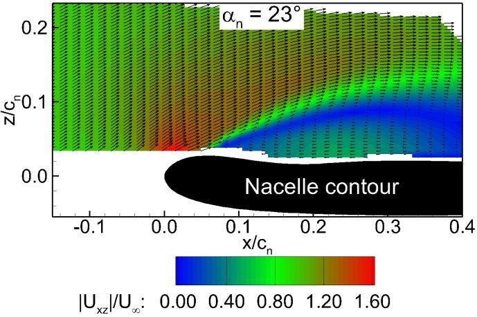
5 (a) t = 35 ms (b) t = 56 ms Fig. 5: Mean in-plane flow field at αn = 19 (a) t = 35 ms (b) t = 56 ms Fig. 6: Mean in-plane flow field at αn = 23 (a) t = 35 ms (b) t = 56 ms Fig. 7: Normalized turbulent kinetic energy at αn = 19 (a) t = 35 ms (b) t = 56 ms Fig. 8: Normalized turbulent kinetic energy at αn =

6 Figures 7 and 8 show the normalized turbulent kinetic energy for the same angles of attack and the corresponding times of Figs. 5 and 6. The arrangement of the Figs. 7 and 8 is consistent with the Figures above. It can be clearly seen that the level of turbulent kinetic energy is relatively high at α n = 23 compared to α n = 19. This is a result of the separated flow at the higher angle of attack. At the time t = 56 ms it is also apparent that the fluctuations of the three velocity components are higher than at t = 35 ms. This result indicates that the counter clockwise rotating vortex enlarges the fluctuations in the flow. If the separation is already present, the separated region will also be increased. Therefore, the impact of the distortion on the flow through the nacelle is considered to be significant and to destabilize the flow in the intake of the engine. Fig. 2 (a) shows that the vortex generator s trailing edge was placed.7 m upstream of the nacelle s leading edge. The convection time of the vortex between the vortex generator and the nacelle is expected to be approximately 47 ms since the experiments are carried out at onstream velocities between. m s and 39 m/s. Therefore, the expected value is slightly smaller than t = 56 ms. This is due to the fact that the time is counted from the initial movement of the vortex generator, while passing α vg = -10. In Fig. 9 an equidistant time series of vector fields of the interaction between the vortex and the nacelle is shown at α n = 19. The black contour is the bottom leading edge of the nacelle, whereas the white point indicates the position, where the Probability Density Function (PDF) of the normalized stream-wise velocity fluctuations u' are calculated, see Fig. 10. The histograms were calculated using 1000 single vector fields at a certain time t. The colors in Fig. 9 indicate the absolute normalized in-plane velocity fluctuations given as ( x ) vg - ( vg - ) ( vg - ). (3) While u' is the velocity fluctuation in the x-direction, w' is the velocity fluctuation in the z-direction. The index α vg = -11 indicates that the mean vector field with the vortex generator at a steady angle of attack of -11 was subtracted from the correspondent phase averaged velocity field at time t. Both mean vector fields were averaged over 1000 single vector fields. (a) t = 30 ms (b) t = 38 ms (c) t = 46 ms (d) t = 54 ms (e) t = 62 ms (f) t = 70 ms Fig. 9: Absolute in-plane fluctuation velocities at α n =
7 (a) t = 30 ms (b) t = 38 ms (c) t = 46 ms (d) t = 54 ms (e) t = 62 ms (f) t = 70 ms Fig. 10: Histograms of the normalized velocity fluctuation for different times t at α n = 19 The vectors in Fig. 9 show the fluctuation velocities u' vg = -11 and w' vg = -11. While Fig. 9 shows the periodic distortion, Fig. 10 shows the turbulent distortion by the vortex. The time spacing between the plotted vector fields is 8 ms. The influence of the counter clockwise rotating vortex on the flow field can be clearly seen in Figs. 9 (c) 9 (e). The near-wall distortions are particularly high in Fig. 9 (d). Therefore, the PDF of the fluctuation velocities u' were calculated in this area. Note that the histograms were calculated for the phase averaged fluctuation velocities. The number of vectors was normalized with the total number of vector fields (i.e. 1000). The bin-width was chosen as.. Figure 10 shows that the fluctuation velocities are relatively small at t = 30 ms, t = 38 ms and t = 70 ms, whereas the fluctuations during the distortion at t = 46 ms to 62 ms are a lot higher. At time t = 54 ms the fluctuation velocities reach an absolute value of. even at the attached angle of attack of the nacelle (i.e. α n = 19 ). These fluctuations are convected downstream and can cause problems at the fan (e.g. stall, rotating stall, or blade vibrations). The histograms in Figs. 10 (c) and 10 (e) show that the fluctuation velocities can also have an unbalanced distribution. The effect of the vortex generator on the separated flow has already been shown in Figs. 6 and 8. However, the effect of the vortex on the probability for reversed flow in the nacelle will be discussed below. Figure 11 shows the ratio of the number of reversed vectors to the total number of vectors downstream the leading edge of the nacelle R rev plotted against the time. This ratio is given by rev Number of vectors u Total number of vectors x c n. (4) It becomes apparent that the peak in both curves is at t 58 ms. This value is higher than the expected convection velocity of the vortex due to the fact that the time is counted from the initial movement of the vortex generator and the vortex needs some time to develop. Figure 11 also shows that the initial state of the ratio of reversed vectors to the total number of 18-7

8 vectors downstream the nacelle s leading edge is not equal to the final state. The reason for that is that the induced velocity due to the vortex generator s airfoil at steady state according to the Biot-Savart law. While at α vg = -11 the effective angle of attack of the nacelle is increased, the effective α n is reduced at α vg = 11. This phenomenon leads to a shift of separation onset. Therefore at α vg = 11, separation onset is shifted towards higher angels of attack. Fig. 11: Probability for reversed flow at α n = 23 The shift of separation onset was shown in static pressure measurements. At α n = 23, when a relatively big turbulent separation bubble has already formed, this effect leads to a decrease of the ratio of reversed flow R rev, see Fig. 11. Figure 12 shows the contour lines of the velocity for different times t in the Fig. 12: Lines of at α n = 23 inlet. This zero velocity in the x-direction indicates the dynamics during the impingement of the vortex on the nacelle. The lines were derived from the SPIV results at each vector position. At t = 40 ms (blue line) the contour of zero velocity has a certain size, which increases up to t = 60 ms. The maximum extension in the radial direction is almost 10% of the nacelles chord, while the axial size of the contour line is approximately 50% of the chord at α n = 23. The amount of reversed velocities decreases after t 58 ms, as shown in Fig. 11. This also means that the contour line of zero velocities decreases, see Fig. 12. It is also shown that the initial state is not the final state, due to the induced flow field by the vortex generator. Additionally, a deformation of the red line (t = 70 ms) of zero velocity can be discovered in Fig. 12. Conclusion The motivation of this experimental investigation was to examine the effect of an atmospheric distortion on the attached as well as the separated flow in a nacelle. The experimental results are a unique validation database in order to develop sophisticated numerical models to calculate the flow at the edge of the flight envelope. The measurements were performed at high angles of attack and low Reynolds numbers of cn.. The investigated model is a generic axially symmetric flow-through nacelle. The boundary layer loading of the nacelle is similar to that of a powered jet intake during take-off and landing and high mass flow rates, see Schulze Distortions are generated by a pitching airfoil in the test section upstream of the nacelle in order to simulate an atmospheric gust. These distortions are judged to have a critical effect on the inlet separation, as the turbulent separation bubble is increased in size by the interaction with the counter clockwise rotating vortex, see Fig. 6. This result was expected as the rotation of the vortex initially increases the angle of attack of the nacelle. The onflow upstream to the compressor is changed significantly. This can change the mechanical loads on the compressor or lead to total pressure losses and therefore reducing the efficiency of the engine. The ratio of reversed vectors to all vectors downstream the leading edge of 18-8
9 the nacelle, indicates that the region of reversed flow is primarily increased. The velocity induced by the vortex generator s airfoil leads to a difference between the initial and the final state of the ratio of the number of reversed vectors to the total number of vectors, see Figs. 11 and 12. Investigations of experiments with attached flow in the nacelle at α n = 19 indicate that the generated distortion has a crucial effect as well. The periodic distortions as well as the turbulent fluctuations in the near-wall region are increased while the vortex interacts with the nacelle, see Figs. 9 and 10. It can be concluded that the vortex generator is adequately constructed to disturb the flow field in this model significantly. The vortex is convected with the free stream velocity of the wind tunnel. The validation of the unsteady pressure measurements, as well as the time resolved SPIV validation, will show if the vortex shedding is influenced by the distortion as well. Furthermore, the effect of the clockwise rotating vortex on the flow has to be investigated. Acknowledgments The authors would like to thank the Deutsche Forschungsgemeinschaft for funding the research within the framework of the research group Simulation of wing and nacelle stall. References Hahn, D., Scholz, P., Radespiel, R., 2012: Vortex Generation in a low speed wind tunnel and vortex interactions with a high-lift airfoil, 30 th AIAA Applied Aerodynamics Conference, doi: / , New Orleans, Louisiana Niehuis, R., Lesser, A., Probst, A., Radespiel, R., Schulze, S., Kähler, C.J., Spiering, F., Kroll, N., Wartzek, F., Schiffer, H.-P., 2013: Simulation of Nacelle Stall and Engine Response, Proceedings of the XXI. International Symposium on Air Breathing Engines (ISABE), Busan, Korea Radespiel, R., Gisele Francois, D., Hoppermann, D., Klein, S., Scholz, P., Wawrzinek, K., Lutz, T., Auerswald, T., Bange, J., Knigge, C., Raasch, S., Kelleners, P., Heinrich, R., Reuß, S., Probst, A., Knopp, T., 2013: Simulation of Wing Stall, 43 rd AIAA Fluid Dynamics Conference, doi: / , San Diego, California Schulze, S., Kähler, C.J., Radespiel, R., 2007: On the Comparison of Stalling Flow-Through Nacelles and Powered Inlets at Take-Off Conditions, 1 st CEAS European Air and Space Conference, Berlin, Germany Schulze, S., 2013: Experimentelle Untersuchungen zur Wirbeldynamik am überziehenden Triebwerkseinlauf, Shaker Verlag, Aachen, Germany Vollmers, H., 2001: Detection of vortices and quantitative evaluation of their main parameters from experimental velocity data, Meas Sci Technol, 12, pp
Active Control of Separated Cascade Flow
 Chapter 5 Active Control of Separated Cascade Flow In this chapter, the possibility of active control using a synthetic jet applied to an unconventional axial stator-rotor arrangement is investigated.
Given a stream function for a cylinder in a uniform flow with circulation: a) Sketch the flow pattern in terms of streamlines.
 Sketch the flow pattern in terms of streamlines.") Question Given a stream function for a cylinder in a uniform flow with circulation: R Γ r ψ = U r sinθ + ln r π R a) Sketch the flow pattern in terms of streamlines. b) Derive an expression for the angular
Question Given a stream function for a cylinder in a uniform flow with circulation: R Γ r ψ = U r sinθ + ln r π R a) Sketch the flow pattern in terms of streamlines. b) Derive an expression for the angular
Studies on the Transition of the Flow Oscillations over an Axisymmetric Open Cavity Model
 Advances in Aerospace Science and Applications. ISSN 2277-3223 Volume 3, Number 2 (2013), pp. 83-90 Research India Publications http://www.ripublication.com/aasa.htm Studies on the Transition of the Flow
Aeroelasticity in Dynamically Pitching Wind Turbine Airfoils
 Aeroelasticity in Dynamically Pitching Wind Turbine Airfoils Andrew Magstadt, John Strike, Michael Hind, Pourya Nikoueeyan, and Jonathan Naughton Dept. of Mechanical Engineering Wind Energy Research Center
INFLUENCE OF ACOUSTIC EXCITATION ON AIRFOIL PERFORMANCE AT LOW REYNOLDS NUMBERS
 ICAS 2002 CONGRESS INFLUENCE OF ACOUSTIC EXCITATION ON AIRFOIL PERFORMANCE AT LOW REYNOLDS NUMBERS S. Yarusevych*, J.G. Kawall** and P. Sullivan* *Department of Mechanical and Industrial Engineering, University
Experimental investigation of flow control devices for the reduction of transonic buffeting on rocket afterbodies
 Experimental investigation of flow control devices for the reduction of transonic buffeting on rocket afterbodies F.F.J. Schrijer 1, A. Sciacchitano 1, F. Scarano 1 1: Faculty of Aerospace Engineering,
Correlations between turbulent wall pressure and velocity field fluctuations in backward-facing step
 DocumentID: 450038 Correlations between turbulent wall pressure and velocity field fluctuations in backward-facing step flows Istvan Bolgar, Sven Scharnowski, and Christian J. Kähler Bundeswehr University
Given the water behaves as shown above, which direction will the cylinder rotate?
 water stream fixed but free to rotate Given the water behaves as shown above, which direction will the cylinder rotate? ) Clockwise 2) Counter-clockwise 3) Not enough information F y U 0 U F x V=0 V=0
THE EFFECT OF SAMPLE SIZE, TURBULENCE INTENSITY AND THE VELOCITY FIELD ON THE EXPERIMENTAL ACCURACY OF ENSEMBLE AVERAGED PIV MEASUREMENTS
 4th International Symposium on Particle Image Velocimetry Göttingen, Germany, September 7-9, 00 PIV 0 Paper 096 THE EFFECT OF SAMPLE SIZE, TURBULECE ITESITY AD THE VELOCITY FIELD O THE EXPERIMETAL ACCURACY
FLOW VISUALIZATION AND PIV MEASUREMENTS OF LAMINAR SEPARATION BUBBLE OSCILLATING AT LOW FREQUENCY ON AN AIRFOIL NEAR STALL
 4 TH INTERNATIONAL CONGRESS OF THE AERONAUTICAL SCIENCES FLOW VISUALIZATION AND PIV MEASUREMENTS OF LAMINAR SEPARATION BUBBLE OSCILLATING AT LOW FREQUENCY ON AN AIRFOIL NEAR STALL Hiroyuki Tanaka Department
Experimental Study on Flow Control Characteristics of Synthetic Jets over a Blended Wing Body Configuration
 Experimental Study on Flow Control Characteristics of Synthetic Jets over a Blended Wing Body Configuration Byunghyun Lee 1), Minhee Kim 1), Chongam Kim 1), Taewhan Cho 2), Seol Lim 3), and Kyoung Jin
Part 3. Stability and Transition
 Part 3 Stability and Transition 281 Overview T. Cebeci 1 Recent interest in the reduction of drag of underwater vehicles and aircraft components has rekindled research in the area of stability and transition.
COMPUTATIONAL SIMULATION OF THE FLOW PAST AN AIRFOIL FOR AN UNMANNED AERIAL VEHICLE
 COMPUTATIONAL SIMULATION OF THE FLOW PAST AN AIRFOIL FOR AN UNMANNED AERIAL VEHICLE L. Velázquez-Araque 1 and J. Nožička 2 1 Division of Thermal fluids, Department of Mechanical Engineering, National University
Simulation of Aeroelastic System with Aerodynamic Nonlinearity
 Simulation of Aeroelastic System with Aerodynamic Nonlinearity Muhamad Khairil Hafizi Mohd Zorkipli School of Aerospace Engineering, Universiti Sains Malaysia, Penang, MALAYSIA Norizham Abdul Razak School
Large-eddy simulations for wind turbine blade: rotational augmentation and dynamic stall
 Large-eddy simulations for wind turbine blade: rotational augmentation and dynamic stall Y. Kim, I.P. Castro, and Z.T. Xie Introduction Wind turbines operate in the atmospheric boundary layer and their
CFD Analysis of Micro-Ramps for Hypersonic Flows Mogrekar Ashish 1, a, Sivakumar, R. 2, b
 Applied Mechanics and Materials Submitted: 2014-04-25 ISSN: 1662-7482, Vols. 592-594, pp 1962-1966 Revised: 2014-05-07 doi:10.4028/www.scientific.net/amm.592-594.1962 Accepted: 2014-05-16 2014 Trans Tech
Contents. I Introduction 1. Preface. xiii
 Contents Preface xiii I Introduction 1 1 Continuous matter 3 1.1 Molecules................................ 4 1.2 The continuum approximation.................... 6 1.3 Newtonian mechanics.........................
Numerical Investigation of the Transonic Base Flow of A Generic Rocket Configuration
 1 Numerical Investigation of the Transonic Base Flow of A Generic Rocket Configuration A. Henze, C. Glatzer, M. Meinke, W. Schröder Institute of Aerodynamics, RWTH Aachen University, Germany March 21,
PROPERTIES OF THE FLOW AROUND TWO ROTATING CIRCULAR CYLINDERS IN SIDE-BY-SIDE ARRANGEMENT WITH DIFFERENT ROTATION TYPES
 THERMAL SCIENCE, Year, Vol. 8, No. 5, pp. 87-9 87 PROPERTIES OF THE FLOW AROUND TWO ROTATING CIRCULAR CYLINDERS IN SIDE-BY-SIDE ARRANGEMENT WITH DIFFERENT ROTATION TYPES by Cheng-Xu TU, a,b Fu-Bin BAO
50 h 3AF International Conference on Applied Aerodynamics March 01 April 2015, Toulouse - France
 50 h 3AF International Conference on Applied Aerodynamics 29-30 March 01 April 2015, Toulouse - France FP10-2015-faure Vortex dynamics resulting from the interaction between two NACA 23 012 airfoils Thierry
Effects of the Leakage Flow Tangential Velocity in Shrouded Axial Compressor Cascades *
 TSINGHUA SCIENCE AND TECHNOLOGY ISSNll1007-0214ll21/21llpp105-110 Volume 14, Number S2, December 2009 Effects of the Leakage Flow Tangential Velocity in Shrouded Axial Compressor Cascades * KIM Jinwook
International Conference on Methods of Aerophysical Research, ICMAR 2008
 International Conference on Methods of Aerophysical Research, ICMAR 8 EXPERIMENTAL STUDY OF UNSTEADY EFFECTS IN SHOCK WAVE / TURBULENT BOUNDARY LAYER INTERACTION P.A. Polivanov, А.А. Sidorenko, A.A. Maslov
Dynamic Stall of an Experimental Wind Turbine Blade
 Dynamic Stall of an Experimental Wind Turbine Blade Matthew Melius and Raúl Bayoán Cal Portland State University, Portland, OR USA 9721 Karen Mulleners École Polytechnique Fédérale de Lausanne, CH-115
An Experimental Validation of Numerical Post-Stall Aerodynamic Characteristics of a Wing
 Proceedings of ICTACEM 2017 International Conference on Theoretical, Applied, Computational and Experimental Mechanics December 28-30, 2017, IIT Kharagpur, India ICTACEM-2017/XXXX(paper No.) An Experimental
NUMERICAL SIMULATION OF STATIC INFLOW DISTORTION ON AN AXIAL FLOW FAN
 Int. J. Mech. Eng. & Rob. Res. 2014 Arun Raj S and Pal Pandian P, 2014 Research Paper ISSN 2278 0149 www.ijmerr.com Vol. 3, No. 2, April 2014 2014 IJMERR. All Rights Reserved NUMERICAL SIMULATION OF STATIC
On the aeroacoustic tonal noise generation mechanism of a sharp-edged. plate
 On the aeroacoustic tonal noise generation mechanism of a sharp-edged plate Danielle J. Moreau, Laura A. Brooks and Con J. Doolan School of Mechanical Engineering, The University of Adelaide, South Australia,
Stall Suppression of a Low-Reynolds-Number Airfoil with a Dynamic Burst Control Plate
 49th AIAA Aerospace Sciences Meeting including the New Horizons Forum and Aerospace Exposition 4-7 January 2011, Orlando, Florida AIAA 2011-1180 Stall Suppression of a Low-Reynolds-Number Airfoil with
Direct Numerical Simulations of Transitional Flow in Turbomachinery
 Direct Numerical Simulations of Transitional Flow in Turbomachinery J.G. Wissink and W. Rodi Institute for Hydromechanics University of Karlsruhe Unsteady transitional flow over turbine blades Periodic
Investigations on Disturbance Amplification in a Laminar Separation Bubble by Means of LDA and PIV
 11 th InternationalSymposium on Applications of Laser Techniques to Fluid Mechanics, 8 th -11 th July 2002, Lisbon, Portugal Investigations on Disturbance Amplification in a Laminar Separation Bubble by
Circulation control using surface plasma actuators for aerodynamic load alleviation on wind turbine airfoils
 Circulation control using surface plasma actuators for aerodynamic load alleviation on wind turbine airfoils P. JOSEPH, A. LEROY, S. BALERIOLA, D. NELSON-GRUEL, Y. HAIDOUS, S. LOYER, P. DEVINANT, S. AUBRUN
High Speed Aerodynamics. Copyright 2009 Narayanan Komerath
 Welcome to High Speed Aerodynamics 1 Lift, drag and pitching moment? Linearized Potential Flow Transformations Compressible Boundary Layer WHAT IS HIGH SPEED AERODYNAMICS? Airfoil section? Thin airfoil
Numerical Investigation of Wind Tunnel Wall Effects on a Supersonic Finned Missile
 16 th International Conference on AEROSPACE SCIENCES & AVIATION TECHNOLOGY, ASAT - 16 May 26-28, 2015, E-Mail: asat@mtc.edu.eg Military Technical College, Kobry Elkobbah, Cairo, Egypt Tel : +(202) 24025292
DYNAMIC STALL ONSET VARIATION WITH REDUCED FREQUENCY FOR THREE STALL MECHANISMS
 International Forum on Aeroelasticity and Structural Dynamics IFASD 27 25-28 June 27 Como, Italy DYNAMIC STALL ONSET VARIATION WITH REDUCED FREQUENCY FOR THREE STALL MECHANISMS Boutet Johan, Dimitriadis
Numerical study of battle damaged two-dimensional wings
 Advances in Fluid Mechanics IX 141 Numerical study of battle damaged two-dimensional wings S. Djellal, T. Azzam, M. Djellab & K. Lakkaichi Fluid Mechanics Laboratory Polytechnical School Bordj El Bahri,
Transition Modeling Activities at AS-C²A²S²E (DLR)
") Transition Modeling Activities at AS-C²A²S²E (DLR) Andreas Krumbein German Aerospace Center (DLR) Institute of Aerodynamics and Flow Technology (AS) C²A²S²E - Center for Computer Applications in AeroSpace
Transition Modeling Activities at AS-C²A²S²E (DLR) Andreas Krumbein German Aerospace Center (DLR) Institute of Aerodynamics and Flow Technology (AS) C²A²S²E - Center for Computer Applications in AeroSpace
Dynamics of Large Scale Motions in Bubble-Driven Turbulent Flow
 Dynamics of Large Scale Motions in Bubble-Driven Turbulent Flow Kyung Chun Kim School of Mechanical Engineering, Pusan National University Jangjeon-dong, Geumjeong-gu, Pusan, 609-735, Korea kckim@pusan.ac.kr
Analysis of the near-wall flow field in shock-cooling-film interaction for varying shock impingement positions
 10 th International Symposium on Turbulence and Shear Flow Phenomena (TSFP10), Chicago, USA, July, 2017 Analysis of the near-wall flow field in shock-cooling-film interaction for varying shock impingement
An experimental study of the vortex structures in the wake of a piezoelectric flapping plate for Nano Air Vehicle applications
 Graduate Theses and Dissertations Iowa State University Capstones, Theses and Dissertations 9 An experimental study of the vortex structures in the wake of a piezoelectric flapping plate for Nano Air Vehicle
SPC Aerodynamics Course Assignment Due Date Monday 28 May 2018 at 11:30
 SPC 307 - Aerodynamics Course Assignment Due Date Monday 28 May 2018 at 11:30 1. The maximum velocity at which an aircraft can cruise occurs when the thrust available with the engines operating with the
Module 3: Velocity Measurement Lecture 15: Processing velocity vectors. The Lecture Contains: Data Analysis from Velocity Vectors
 The Lecture Contains: Data Analysis from Velocity Vectors Velocity Differentials Vorticity and Circulation RMS Velocity Drag Coefficient Streamlines Turbulent Kinetic Energy Budget file:///g /optical_measurement/lecture15/15_1.htm[5/7/2012
Empirical study of the tonal noise radiated by a sharpedged flat plate at low-to-moderate Reynolds number
 Paper Number 44, Proceedings of ACOUSTICS 2011 Empirical study of the tonal noise radiated by a sharpedged flat plate at low-to-moderate Reynolds number Danielle J. Moreau, Laura A. Brooks and Con J. Doolan
Near-wall Reynolds stress modelling for RANS and hybrid RANS/LES methods
 Platzhalter für Bild, Bild auf Titelfolie hinter das Logo einsetzen Near-wall Reynolds stress modelling for RANS and hybrid RANS/LES methods Axel Probst (now at: C 2 A 2 S 2 E, DLR Göttingen) René Cécora,
Unsteady flow over flexible wings at different low Reynolds numbers
 EPJ Web of Conferences 114, 02030 (2016) DOI: 10.1051/ epjconf/ 2016114 02030 C Owned by the authors, published by EDP Sciences, 2016 Unsteady flow over flexible wings at different low Reynolds numbers
WIND TUNNEL EXPERIMENTS TO TEACH PHYSICS
 WIND TUNNEL EXPERIMENTS TO TEACH PHYSICS S. Le Clainche 1, M. Schlapkohl 2, V. Theofilis 1, H. Wei 1, J.A. Tendero 1, Q. Liu 1, J.M. Pérez 1 1 Universidad Politécnica de Madrid (SPAIN) 2 Deutsche Schule
POD ANALYSIS OF THE WAKE-BOUNDARY LAYER UNSTEADY INTERACTION IN A LPT BLADE CASCADE
 POD ANALYSIS OF THE WAKE-BOUNDARY LAYER UNSTEADY INTERACTION IN A LPT BLADE CASCADE M. Berrino, D. Lengani, D. Simoni, M. Ubaldi, P. Zunino DIME - Universitá di Genova, Via Montallegro 1, I-16145 Genoa,
ADVERSE REYNOLDS NUMBER EFFECT ON MAXIMUM LIFT OF TWO DIMENSIONAL AIRFOILS
 ICAS 2 CONGRESS ADVERSE REYNOLDS NUMBER EFFECT ON MAXIMUM LIFT OF TWO DIMENSIONAL AIRFOILS Kenji YOSHIDA, Masayoshi NOGUCHI Advanced Technology Aircraft Project Center NATIONAL AEROSPACE LABORATORY 6-
Aerodynamic Investigation of a 2D Wing and Flows in Ground Effect
 26 2 2009 3 CHINESE JOURNAL OF COMPUTATIONAL PHYSICS Vol. 26,No. 2 Mar., 2009 Article ID : 10012246 X(2009) 0220231210 Aerodynamic Investigation of a 2D Wing and Flows in Ground Effect YANG Wei, YANG Zhigang
Design of a Droopnose Configuration for a Coanda Active Flap Application. Marco Burnazzi and Rolf Radespiel
 Design of a Droopnose Configuration for a Coanda Active Flap Application Marco Burnazzi and Rolf Radespiel Institute of Fluid Mechanics, Technische Universität Braunschweig, 38108 Braunschweig, Germany
Interferometry and Computational Studies of an Oscillating Airfoil Compressible Dynamic Stall
 Calhoun: The NPS nstitutional Archive Faculty and Researcher Publications Faculty and Researcher Publications Collection 1992 nterferometry and Computational Studies of an Oscillating Airfoil Compressible
THE EFFECT OF INTERNAL ACOUSTIC EXCITATION ON THE AERODYNAMIC CHARACTERISTICS OF AIRFOIL AT HIGH ANGLE OF ATTACKE
 Vol.1, Issue.2, pp-371-384 ISSN: 2249-6645 THE EFFECT OF INTERNAL ACOUSTIC EXCITATION ON THE AERODYNAMIC CHARACTERISTICS OF AIRFOIL AT HIGH ANGLE OF ATTACKE Dr. Mohammed W. Khadim Mechanical Engineering
INVESTIGATION OF UNSTEADY TRANSONIC FLOW FIELD ABOVE LAMINAR AIRFOIL BY PIV METHOD
 INVESTIGATION OF UNSTEADY TRANSONIC FLOW FIELD ABOVE LAMINAR AIRFOIL BY PIV METHOD Wit Stryczniewicz*, Robert Placek*, Paweł Ruchała* *Institute of Aviation, Krakowska 110/114, 02-256 Warsaw, Poland Keywords:
Detached Eddy Simulation on Hypersonic Base Flow Structure of Reentry-F Vehicle
 Available online at www.sciencedirect.com ScienceDirect Procedia Engineering 00 (2014) 000 000 www.elsevier.com/locate/procedia APISAT2014, 2014 Asia-Pacific International Symposium on Aerospace Technology,
INFLUENCE OF AIR COOLING AND AIR-JET VORTEX GENERATOR ON FLOW STRUCTURE IN TURBINE PASSAGE
 TASKQUARTERLYvol.19,No2,2015,pp.153 166 INFLUENCE OF AIR COOLING AND AIR-JET VORTEX GENERATOR ON FLOW STRUCTURE IN TURBINE PASSAGE RYSZARD SZWABA, PAWEŁ FLASZYŃSKI, JAN ARTUR SZUMSKI AND PIOTR DOERFFER
Reynolds number influence on high agility aircraft vortical flows
 Reynolds number influence on high agility aircraft vortical flows TUM-AER project proposal Outline Background and context Previous investigations Proposed ETW measurements Project aims Institute of Aerodynamics
DYNAMIC SEPARATION CONTROL IN A LOW-SPEED ASYMMETRIC DIFFUSER WITH VARYING DOWNSTREAM BOUNDARY CONDITION
 AIAA 23-4161 DYNAMIC SEPARATION CONTROL IN A LOW-SPEED ASYMMETRIC DIFFUSER WITH VARYING DOWNSTREAM BOUNDARY CONDITION Samantha H. Feakins, Douglas G. MacMartin, and Richard M. Murray California Institute
International Conference on Energy Efficient Technologies For Automobiles (EETA 15) Journal of Chemical and Pharmaceutical Sciences ISSN:
 Journal of Chemical and Pharmaceutical Sciences ISSN:") HEAT TRANSFER ENHANCEMENT WITH PRESSURE LOSS REDUCTION IN COMPACT HEAT EXCHANGERS USING VORTEX GENERATORS Viswajith M V*, Gireesh Kumaran Thampi, James Varghese Department of Mechanical Engineering, School
HEAT TRANSFER ENHANCEMENT WITH PRESSURE LOSS REDUCTION IN COMPACT HEAT EXCHANGERS USING VORTEX GENERATORS Viswajith M V*, Gireesh Kumaran Thampi, James Varghese Department of Mechanical Engineering, School
MODIFICATION OF AERODYNAMIC WING LOADS BY FLUIDIC DEVICES
 Journal of KONES Powertrain and Transport, Vol. 21, No. 2 2014 MODIFICATION OF AERODYNAMIC WING LOADS BY FLUIDIC DEVICES Institute of Aviation Department of Aerodynamics and Flight Mechanics Krakowska
coh R 1/2 K x = S R 1R 2 (K x) S R 1 (K) S R 2 (K) (3) Davenport (1961) proposed one of the first heuristic root-coherence expressions for longitudina
 S R 1 (K) S R 2 (K) (3) Davenport (1961) proposed one of the first heuristic root-coherence expressions for longitudina") The Seventh International Colloquium on Bluff Body Aerodynamics and Applications (BBAA7) Shanghai China; September 2-6 2012 Investigation of spatial coherences of aerodynamic loads on a streamlined bridge
The Seventh International Colloquium on Bluff Body Aerodynamics and Applications (BBAA7) Shanghai China; September 2-6 2012 Investigation of spatial coherences of aerodynamic loads on a streamlined bridge
Experimental and numerical investigation of secondary flow on compressor blades
 Experimental and numerical investigation of secondary flow on compressor blades A. Hergt *, R. Meyer * German Aerospace Center (DLR); Institute of Propulsion Technology; Dept. of Turbulence Research; Müller-Breslau-Str.
The E80 Wind Tunnel Experiment the experience will blow you away. by Professor Duron Spring 2012
 The E80 Wind Tunnel Experiment the experience will blow you away by Professor Duron Spring 2012 Objectives To familiarize the student with the basic operation and instrumentation of the HMC wind tunnel
Performance. 5. More Aerodynamic Considerations
 Performance 5. More Aerodynamic Considerations There is an alternative way of looking at aerodynamic flow problems that is useful for understanding certain phenomena. Rather than tracking a particle of
Relationship between Unsteady Fluid Force and Vortex Behavior around a Discoid Airfoil Simulating a Hand of Swimmer
 45 * Relationship between Unsteady Fluid Force and Vortex Behavior around a Discoid Airfoil Simulating a Hand of Swimmer Hiroaki HASEGAWA, Department of Mechanical Engineering, Akita University Jun WATANABE,
Journal of Fluid Science and Technology
 Science and Technology LDV and PIV Measurements of the Organized Oscillations of Turbulent Flow over a Rectangular Cavity* Takayuki MORI ** and Kenji NAGANUMA ** **Naval Systems Research Center, TRDI/Ministry
Experimental Studies for Visualization of Flow with Boundary Layers in an Axial Compressor Fan Inlet using Pressure Probes
 Indian Journal of Science and Technology, Vol 9(45), DOI: 10.17485/ijst/2016/v9i45/104694, December 2016 ISSN (Print) : 0974-6846 ISSN (Online) : 0974-5645 Experimental Studies for Visualization of Flow
AEROACOUSTIC INVESTIGATION OF THE EFFECT OF A DETACHED FLAT PLATE ON THE NOISE FROM A SQUARE CYLINDER
 Abstract AEROACOUSTIC INVESTIGATION OF THE EFFECT OF A DETACHED FLAT PLATE ON THE NOISE FROM A SQUARE CYLINDER Aniket D. Jagtap 1, Ric Porteous 1, Akhilesh Mimani 1 and Con Doolan 2 1 School of Mechanical
Department of Mechanical Engineering
 Department of Mechanical Engineering AMEE401 / AUTO400 Aerodynamics Instructor: Marios M. Fyrillas Email: eng.fm@fit.ac.cy HOMEWORK ASSIGNMENT #2 QUESTION 1 Clearly there are two mechanisms responsible
Rohrströhmungsverhalten bei Drallerzeugung: Validierung von CFD Simulationen mit Laser-Doppler Anemometrie
 Fachtagung Lasermethoden in der Strömungsmesstechnik 8. 10. September 2015, Dresden Rohrströhmungsverhalten bei Drallerzeugung: Validierung von CFD Simulationen mit Laser-Doppler Anemometrie Characteristics
Experimental investigation of the aerodynamic characteristics of generic fan-in-wing configurations
 THE AERONAUTICAL JOURNAL JANUARY 2009 VOLUME 113 NO 1139 9 Experimental investigation of the aerodynamic characteristics of generic fan-in-wing configurations N. Thouault, C. Breitsamter and N. A. Adams
Brenda M. Kulfan, John E. Bussoletti, and Craig L. Hilmes Boeing Commercial Airplane Group, Seattle, Washington, 98124
 AIAA--2007-0684 Pressures and Drag Characteristics of Bodies of Revolution at Near Sonic Speeds Including the Effects of Viscosity and Wind Tunnel Walls Brenda M. Kulfan, John E. Bussoletti, and Craig
STUDY OF SHOCK MOVEMENT AND UNSTEADY PRESSURE ON 2D GENERIC MODEL
 STUDY OF SHOCK MOVEMENT AND UNSTEADY PRESSURE ON D GENERIC MODEL Davy Allegret-Bourdon Chair of Heat and Power Technology Royal Institute of Technology, Stockholm, Sweden davy@energy.kth.se Torsten H.
Effect of Pivot Point on Aerodynamic Force and Vortical Structure of Pitching Flat Plate Wings
 5st AIAA Aerospace Sciences Meeting including the New Horizons Forum and Aerospace Exposition 7 - January 23, Grapevine (Dallas/Ft. Worth Region), Texas AIAA 23-792 Effect of Pivot Point on Aerodynamic
STUDY OF THE SECONDARY FLOW STRUCTURES CAUSED THE ADDITION FORWARD FACING STEP TURBULENCE GENERATED
 Advances and Applications in Fluid Mechanics 2015 Pushpa Publishing House, Allahabad, India Published Online: May 2015 http://dx.doi.org/10.17654/aafmjul2015_129_144 Volume 18, Number 1, 2015, Pages 129-144
What is the crack propagation rate for 7075-T6 aluminium alloy.
 - 130 - APPENDIX 4A 100 QUESTIONS BASED ON SOURCE DOCUMENTS LISTED IN APPENDIX 4B 20-06 Magnitude of reductions in heat transfer on the nose region of a body when ablation of the surface takes place. (PI2002)
PIV study for the analysis of planar jets in cross-flow at low Reynolds number
 PIV study for the analysis of planar jets in cross-flow at low Reynolds number Vincenti I., Guj G., Camussi R., Giulietti E. University Roma TRE, Department of Ingegneria Meccanica e Industriale (DIMI),
PIV INVESTIGATION OF THE INTERNAL FLOW STRUCTURE IN A CENTRIFUGAL PUMP IMPELLER
 PIV INVESTIGATION OF THE INTERNAL FLOW STRUCTURE IN A CENTRIFUGAL PUMP IMPELLER N. Pedersen (np@et.dtu.dk) 1 and C.B. Jacobsen 2 1 Dept. of Energy Engineering, Fluid Mechanics Section Building 43, Technical
Theoretical Gas Flow through Gaps in Screw-type Machines
 Theoretical Gas Flow through Gaps in Screw-type Machines Prof. Dr.-Ing. K. Kauder, Dipl.-Ing. D. Stratmann University of Dortmund, Fachgebiet Fluidenergiemaschinen (The experimental part of these studies
ACTIVE SEPARATION CONTROL ON A SLATLESS 2D HIGH-LIFT WING SECTION
 26th INTERNATIONAL CONGRESS OF THE AERONAUTICAL SCIENCES ACTIVE SEPARATION CONTROL ON A SLATLESS 2D HIGH-LIFT WING SECTION F. Haucke, I. Peltzer, W. Nitsche Chair for Aerodynamics Department of Aeronautics
Boundary-Layer Theory
 Hermann Schlichting Klaus Gersten Boundary-Layer Theory With contributions from Egon Krause and Herbert Oertel Jr. Translated by Katherine Mayes 8th Revised and Enlarged Edition With 287 Figures and 22
Vortex-Array Model of a Shear Layer Perturbed by a Periodically Pitching Airfoil
 AIAA Aviation 1- June 1, Atlanta, GA th AIAA Fluid Dynamics Conference AIAA 1-53 Vortex-Array Model of a Shear Layer Perturbed by a Periodically Pitching Airfoil K. Zhang 1 Xi an Jiaotong University, Xi
Aerodynamic Rotor Model for Unsteady Flow and Wake Impact
 Aerodynamic Rotor Model for Unsteady Flow and Wake Impact N. Bampalas, J. M. R. Graham Department of Aeronautics, Imperial College London, Prince Consort Road, London, SW7 2AZ June 28 1 (Steady Kutta condition)
Experimental investigation of separated shear layer from a leading edge subjected to various angles of attack with tail flap deflections
 Sādhanā Vol. 40, Part 3, May 2015, pp. 803 817. c Indian Academy of Sciences Experimental investigation of separated shear layer from a leading edge subjected to various angles of attack with tail flap
Vortex Generator Induced Flow in a High Re Boundary Layer
 Downloaded from orbit.dtu.dk on: Dec 20, 2017 Vortex Generator Induced Flow in a High Re Boundary Layer Velte, Clara Marika; Braud, C.; Coudert, S.; Foucaut, J.-M. Published in: Proceedings of Torque 2012,
Effect of Airfoil Aerodynamic Loading on Trailing-Edge Noise Sources
 AIAA JOURNAL Vol. 43, No. 1, January 2005 Effect of Airfoil Aerodynamic Loading on Trailing-Edge Noise Sources Stéphane Moreau Valeo Motors and Actuators, 78321 La Verrière, France and Michel Roger Ecole
Multiphase Science and Technology, Vol. 16, Nos. 1-4, pp. 1-20, 2005
 Multiphase Science and Technology, Vol. 16, Nos. 1-4, pp. 1-2, 25 EXPERIMENTS ON THE TURBULENT STRUCTURE AND THE VOID FRACTION DISTRIBUTION IN THE TAYLOR BUBBLE WAKE L. Shemer, A. Gulitski and D. Barnea
Analysis of the high Reynolds number 2D tests on a wind turbine airfoil performed at two different wind tunnels
 Analysis of the high Reynolds number 2D tests on a wind turbine airfoil performed at two different wind tunnels O.Pires 1, X.Munduate 2, O.Ceyhan 3, M.Jacobs 4, J.Madsen 5 1 National Renewable Energy Centre
Experimental Aerodynamics. Experimental Aerodynamics
 Lecture 3: Vortex shedding and buffeting G. Dimitriadis Buffeting! All structures exposed to a wind have the tendency to vibrate.! These vibrations are normally of small amplitude and have stochastic character!
ME 425: Aerodynamics
 ME 45: Aerodynamics Dr. A.B.M. Toufique Hasan Professor Department of Mechanical Engineering Bangladesh University of Engineering & Technology (BUET), Dhaka Lecture-0 Introduction toufiquehasan.buet.ac.bd
Simultaneous Velocity and Concentration Measurements of a Turbulent Jet Mixing Flow
 Simultaneous Velocity and Concentration Measurements of a Turbulent Jet Mixing Flow HUI HU, a TETSUO SAGA, b TOSHIO KOBAYASHI, b AND NOBUYUKI TANIGUCHI b a Department of Mechanical Engineering, Michigan
Relaminerization of a Highly Accelerated Flow on a Convex Curvature
 Relaminerization of a Highly Accelerated Flow on a Convex Curvature Abstract Relaminarization of turbulent flow is a process by which the mean flow reverts to an effectively laminar state. The phenomenon
Open Access Experimental Research and Analysis of Vortex Excited Vibration Suppression of Spiral Stripe Strake
 Send Orders for Reprints to reprints@benthamscience.ae The Open Mechanical Engineering Journal, 2014, 8, 941-947 941 Open Access Experimental Research and Analysis of Vortex Excited Vibration Suppression
COMPUTATIONAL STUDY OF SEPARATION CONTROL MECHANISM WITH THE IMAGINARY BODY FORCE ADDED TO THE FLOWS OVER AN AIRFOIL
 COMPUTATIONAL STUDY OF SEPARATION CONTROL MECHANISM WITH THE IMAGINARY BODY FORCE ADDED TO THE FLOWS OVER AN AIRFOIL Kengo Asada 1 and Kozo Fujii 2 ABSTRACT The effects of body force distribution on the
Chapter 5 Phenomena of laminar-turbulent boundary layer transition (including free shear layers)
") Chapter 5 Phenomena of laminar-turbulent boundary layer transition (including free shear layers) T-S Leu May. 3, 2018 Chapter 5: Phenomena of laminar-turbulent boundary layer transition (including free
Chapter 5 Phenomena of laminar-turbulent boundary layer transition (including free shear layers) T-S Leu May. 3, 2018 Chapter 5: Phenomena of laminar-turbulent boundary layer transition (including free
An Experimental Investigation of Perturbations on Vortex Breakdown over Delta Wings
 6 th Australasian Fluid Mechanics Conference Crown Plaza, Gold Coast, Australia 2-7 December 27 An Experimental Investigation of Perturbations on Vortex Breakdown over Delta Wings S. Srigrarom and M. Ridzwan
VORTICITY FIELD EVOLUTION IN A FORCED WAKE. Richard K. Cohn Air Force Research Laboratory Edwards Air Force Base, CA 92524
 Proceedings of the st International Symposium on Turbulence and Shear Flow Phenomena, Santa Barbara, CA, Sep. 5, 999, Eds. Banerjee, S. and Eaton, J. K., pp. 9-96. VORTICITY FIELD EVOLUTION IN A FORCED
General Solution of the Incompressible, Potential Flow Equations
 CHAPTER 3 General Solution of the Incompressible, Potential Flow Equations Developing the basic methodology for obtaining the elementary solutions to potential flow problem. Linear nature of the potential
Aeroelastic Gust Response
 Aeroelastic Gust Response Civil Transport Aircraft - xxx Presented By: Fausto Gill Di Vincenzo 04-06-2012 What is Aeroelasticity? Aeroelasticity studies the effect of aerodynamic loads on flexible structures,
Analysis of Wind Turbine Pressure Distribution and 3D Flows Visualization on Rotating Condition
 IOSR Journal of Engineering (IOSRJEN) ISSN (e): 2250-3021, ISSN (p): 2278-8719 Vol. 06, Issue 02 (February. 2016), V1 PP 18-30 www.iosrjen.org Analysis of Wind Turbine Pressure Distribution and 3D Flows
Experimental Studies on Complex Swept Rotor Blades
 International Journal of Engineering Research and Technology. ISSN 974-3154 Volume 6, Number 1 (213), pp. 115-128 International Research Publication House http://www.irphouse.com Experimental Studies on
ACTIVE SEPARATION CONTROL PROCESS OVER A SHARP EDGE RAMP
 June 30 - July 3, 2015 Melbourne, Australia 9 3D-1 ACTIVE SEPARATION CONTROL PROCESS OVER A SHARP EDGE RAMP Antoine Debien 8 rue Léonard de Vinci antoine.debien@univ-orleans.fr Sandrine Aubrun sandrine.aubrun@univ-orleans.fr
Molecular tagging velocimetry measurements of axial flow in a concentrated vortex core
 PHYSICS OF FLUIDS VOLUME 16, NUMBER 11 NOVEMBER 2004 Molecular tagging velocimetry measurements of axial flow in a concentrated vortex core Douglas G. Bohl Naval Surface Warfare Center Indian Head Division,