Finite Element-Based Failure Models for Carbon/Epoxy Tape Composites
|
|
|
- Gwen Dalton
- 6 years ago
- Views:
Transcription
1 Finite Element-Based Failure Models for Carbon/Epoxy Tape Composites A Master Thesis Presented to The Academic Faculty by Guillaume Seon In Partial Fulfillment of the Requirements for the Degree Master of Science in Aerospace Engineering Daniel Guggenheim School of Aerospace Engineering Georgia Institute of Technology May 2009 Copyright 2009 by Guillaume Seon
2 Finite Element-Based Failure Models for Carbon/Epoxy Tape Composites Approved by: Dr. Andrew Makeev, Advisor Daniel Guggenheim School of Aerospace Engineering Georgia Institute of Technology Dr. Olivier Bauchau Daniel Guggenheim School of Aerospace Engineering Georgia Institute of Technology Dr. Erian Armanios Daniel Guggenheim School of Aerospace Engineering Georgia Institute of Technology Date Approved: March 16, 2009
3 ACKNOWLEDGEMENTS I would like first to express my greatest gratitude to my advisor, Dr. Andrew Makeev, who inspired me to step into composite material failure mechanisms. His supervision, advice and guidance as well as his wide experience in composite science and scientist intuition are the backbone of this work. His enthusiasm and competence nourished my wish to work in the field of composite materials in the aerospace industry. I would also like to deeply thank senior research engineer Dr. Yuri Nikishkov for all his generous assistance and especially for kindly sharing his finite elements models with me. His critical comments on my work, discussions and his knowledge in computational coding have been extremely helpful for this study. I thank the committee members Dr. Olivier Bauchau and Dr. Erian Armanios for reading this thesis and for their comments and suggestions. I wish to thank Ph.D. student Yihong He who helped me to get introduced to finite element software ABAQUS in the early stages of this work. I would like to express my gratitude to all my friends that shared with me this experience as a graduate student in the United States, for all the support, the comradeship and caring they provided. Lastly I wish to thank my parents for their encouragement and education they gave me and made that work and experience abroad possible. iii
4 TABLE OF CONTENTS ACKNOWLEDGEMENTS... iii LIST OF TABLES... vi LIST OF FIGURES... vii SUMMARY... x CHAPTER 1: INTRODUCTION...1 CHAPTER 2: Failure prediction for carbon/epoxy Tape Laminates with Wavy Plies Problem Presentation Material Characterization Linear properties Nonlinear Interlaminar Shear Stress-Strain Relations Finite Element Analysis for Large Wrinkle Coupons ABAQUS Finite Element Model Plane Stress Mesh Non-linear Interlaminar Shear Properties Local Material Orientation Finite Element Predictions Test Data Comparison Finite Element Analysis for Small Wrinkle Coupons ABAQUS Finite Element Model Finite Element Predictions Test Data Comparison Suggestions to Assess the Porosity Problem Modifying the Geometry Modifying the Material Strength...47 iv
5 CHAPTER 3: Failure Prediction for Open Hole Carbon/epoxy Laminate Problem Presentation ABAQUS Finite Element Model D Finite Element Mesh Mesh Convergence Failure Model Damage Initiation Criterion Damage Propagation Finite Element Analysis Results and Test Comparison Fiber Oriented Finite Element Mesh Finite Element Analysis Results and Test Data Comparison Matrix Cracking Initiation and Propagation Test Data Correlation...66 CHAPTER 4: CONCLUSION...70 REFERENCES...72 v
6 LIST OF TABLES Table 1. Cross-Section Dimensions and Loads at Matrix Cracking for Ply-Termination Coupons...8 Table 2. Maximum Tensile Strain before Matrix Failure...10 Table 3. IM7/8552 Tape Stiffness Data [10]...10 Table 4. IM7/8552 Tape Stiffness and Strength Properties...13 Table 5. Interlaminar Shear Strength and Stiffness Values...16 Table 6. Failure Load Predictions for IM7/8552 Tape Wrinkle Coupons...22 Table 7. Cross-Section Dimensions and Failure Loads for Large-Wrinkle Coupons...25 Table 8. Summary of Predictions and Test Data for Wrinkle Coupons...34 Table 9. Failure Load Predictions for IM7/8552 Tape Small Wrinkle Coupons...36 Table 10. Test Data and FEM Predictions for Maximum Strains...42 Table 11. Predicted and Tested Failure Loads for Small Wrinkle Coupons...43 Table 12. Influence of Parameter b in Mesh Convergence for Maximum Stresses...53 Table 13. Dependencies on Damage Field Variables for Matrix Cracking...61 Table 14. Summary of Predictions and Test Data for Hole Coupon...68 vi
7 LIST OF FIGURES Figure 1. IM7/8552 Carbon/Epoxy Tape Large-Wrinkle Coupons...4 Figure 2. IM7/8552 Carbon/Epoxy Tape Small-Wrinkle Coupons...5 Figure 3. Presence of porosity for small-wrinkle coupon C1...6 Figure 4. IM7/8552 Carbon/Epoxy Tape Ply-Termination Coupon A2...7 Figure 5. Lagrange Strain Contour Plots for Coupon A2 at 892 lbs Tension...9 Figure 6. Lagrange Strain Contour Plots for Coupon A2 at 1031 lbs Tension...9 Figure 7. Measured and Calculated Loads for Coupon A Figure 8. IM7/8552 Carbon/Epoxy Tape SBS Test Coupon...14 Figure 9. IM7/8552 Carbon/Epoxy SBS Coupon Failure...14 Figure 10. Shear Stress-Strain Response for Unidirectional IM7/8552 Tape Specimens...15 Figure 11. ABAQUS Sketch for Coupon B2 Geometry...17 Figure 12. Plane Stress Finite Element Mesh for B2 Wrinkle Coupon...17 Figure 13. Convergence of USDFLD non-linear shear stress-strain algorithm...19 Figure 14. Element Based local Coordinate System...20 Figure 15. User Defined Orientation Systems at The Main Wrinkle for B2 FEM...21 Figure 16. Hashin Criterion Contour Plot for Coupon B1 at 3682lbs Tension...23 Figure 17. Hashin Criterion Contour Plot for Coupon B2 at 3360lbs Tension...23 Figure 18. Hashin Criterion Contour Plot for Coupon B3 at 3905lbs Tension...23 Figure 19. ITS Criterion Contour Plot for Coupon B1 at 4296lbs Tension...24 Figure 20. ITS Criterion Contour Plot for Coupon B2 at 3763lbs Tension...24 Figure 21. ITS Criterion Contour Plot for Coupon B3 at 4223lbs Tension...24 Figure 22. Interlaminar Strain Contour Plots for Coupon B1 at 4227 lbs Tension...27 vii
8 Figure 23. Interlaminar Strain Contour Plots for Coupon B2 at 3544 lbs Tension...28 Figure 24. Interlaminar Strain Contour Plots for Coupon B3 at 4097lbs Tension...29 Figure 25. Lagrange Strain Contour Plots for Coupon B1 at 4227 lbs Tension...30 Figure 26. Lagrange Strain Contour Plots for Coupon B1 at 4248 lbs Tension...31 Figure 27. Lagrange Strain Contour Plots for Coupon B2 at 3544 lbs Tension...31 Figure 28. Lagrange Strain Contour Plots for Coupon B2 at 3550 lbs Tension...32 Figure 29. Lagrange Strain Contour Plots for Coupon B3 at 4097 lbs Tension...32 Figure 30. Lagrange Strain Contour Plots for Coupon B3 at 4101 lbs Tension...33 Figure 31. Plane Stress Finite Element Mesh for Coupon C Figure 32. Hashin and ITS Contour Plots for Coupon C1 at Predicted Failure Loads 37 Figure 33. Hashin and ITS Contour Plots for Coupon C2 at Predicted Failure Loads 37 Figure 34. Hashin and ITS Contour Plots for Coupon C3 at Predicted Failure Loads 37 Figure 35. Figure 36. Figure 37. Strain Contour Plots for Coupon C1 at 3086lbs Tension...39 Strain Contour Plots for Coupon C2 at 3129lbs Tension...40 Strain Contour Plots for Coupon C3 at 3156lbs Tension...41 Figure 38. High Strain Concentration Due to Porosity Void for Coupon C Figure 39. Global and Submodel Mesh Details for Geometry Enclosed Void Figure 40. Interlaminar Tensile Strain for C1 at 3156lbs Tension with Rectangular Cavity Figure 41. Subsurface (X-Ray) and Surface (DIC) Images just before Ultimate Failure...50 Figure 42. Global and Sub-model 3D Finite Element Model for Open Hole Coupon..51 Figure 43. Mesh Seed Parameters for Mesh Convergence Study...52 Figure 44. Stresses Plotting Path for Mesh Convergence Study...53 Figure 45. Influence of Circumferential Parameter a for S 22 Convergence...54 Figure 46. Influence of Radial Parameter c for S 22 Convergence...54 viii
9 Figure 47. Influence of Through-thickness Parameter t for S 22 Convergence...55 Figure 48. Influence of Circumferential Parameter a for S 12 Convergence...55 Figure 49. Influence of Radial Parameter c for S 12 Convergence...55 Figure 50. Influence of Through-thickness Parameter t for S 12 Convergence...56 Figure 51. Influence of Circumferential Parameter a for S 33 Convergence...56 Figure 52. Influence of Radial Parameter c for S 33 Convergence...56 Figure 53. Influence of Through-thickness Parameter t for S 33 Convergence...57 Figure 54. Damage Contour plot at 6240lbs for 90 deg surface ply...62 Figure 55. Global and Sub-model Meshes for Open Hole Coupon Analysis...63 Figure 56. Damage Plot for Open-Hole Coupon at 4226 lbs Tension...64 Figure 57. Damage Plot for Open-Hole Coupon at 4991 lbs Tension...64 Figure 58. Damage Plot for Open Hole Coupon at 5953 lbs Tension...65 Figure 59. Damage Plot for Open Hole Coupon at 8475 lbs Tension...65 Figure 60. Ultimate Failure Crack for Open Hole Coupon Figure 61. Surface Transverse Strain Correlation at 1st 45 deg. Crack Development Figure 62. Surface Shear Strain Correlation at 1st 45 deg. Crack Development...67 Figure 63. Surface Transverse Strain Correlation at Ultimate Crack Development...67 Figure 64. Surface Shear Strain Correlation at Ultimate Crack Development...68 ix
10 SUMMARY Laminated carbon/epoxy composite structures are increasingly used in the aerospace industries. Low weight, elastic tailoring, and high durability make the composite materials well suited for replacement of conventional metallic structures. However the difficulty to capture structural failure phenomena is a significant barrier to more extensive use of laminated composites. Predictions are challenging because matrix (resin) dominated failure mechanisms such as delaminations and matrix cracking contribute to the structural failure in addition to fiber-dominated failures. A key to rigorous failure predictions for composites is availability of measurements to quantify structural model parameters including matrixdominated stress-strain relations and failure criteria. Novel techniques for measurement of nonlinear interlaminar constitutive properties in tape composites have been recently developed at Georgia Institute of Technology. Development of methods for accurate predictions of failure in carbon/epoxy tape laminate configurations with complex lay-ups is the main focus of this work. Failures through delamination and matrix cracking are considered. The first objective of this effort is to implement nonlinear interlaminar shear stress-strain relations for IM7/8552 carbon/epoxy tape in ABAQUS finite element models and validate structural delamination failure predictions with tests. Test data for composite configurations with wavy fibers confirm that nonlinear interlaminar shear stress-strain response enables accurate failure prediction. The problem of the presence of porosity and its influence on failure was noted. The second objective is to assess the ability to simulate initiation and propagation of matrix-ply cracking. Failure models for IM7/8552 carbon/epoxy tape open-hole tensile coupons are built and validated. x
11 CHAPTER 1: INTRODUCTION Laminated carbon/epoxy composite structures are increasingly used in the aerospace industries. Low weight, elastic tailoring, and high durability make the composite materials well suited for replacement of conventional metallic structures. However anisotropy and non-linear stress-strain response as well as complexity of the failure processes contribute to the complexity of their structural behavior. One of the most significant barriers to more extensive use of laminate composite materials is the difficulty to capture structural failure phenomena. Predictions are challenging because matrix (resin) dominated failure mechanisms such as delaminations and matrix cracking contribute to the structural failure in addition to fiber-dominated failures. A key to rigorous failure predictions for composites is availability of measurements to quantify structural model parameters including matrix-dominated stress-strain relations and failure criteria. Accurate transverse (through-the-thickness) constitutive properties are especially important for structural analysis of thick composites. Examples of thick composite applications include rotor blade spar and blade-to-hub attachment structural details of rotary wing aircraft [1]. Carbon/epoxy materials such as IM7/8552 tape are oftentimes used for such structures. The problem of structural failure predictions in carbon/epoxy composites has received a lot of attention from researchers over the past years. Finite element-based techniques such as cohesive zone models have been developed to address the matrix-dominated failure phenomena including delaminations and ply-cracks [2]. Researchers also worked on the definition of accurate failure criteria taking into consideration combined effects of different failure modes and fracture-corrected strength properties [3]. Good correlation 1
12 between predictions and experimental results has been demonstrated for simple (not practical) laminate configurations with small number of plies [2]. Development of methods for accurate predictions of failure in carbon/epoxy tape laminate configurations with complex lay-ups is the main focus of this work. Non-linear interlaminar constitutive properties are required for accurate failure predictions of thick composites [4]. In this work the non-linear interlaminar constitutive properties are included in finite element-based models and failure criteria. Novel techniques for measurement of nonlinear interlaminar constitutive properties in composites have been recently developed at Georgia Institute of Technology [4]. The first objective of this effort is to implement the nonlinear interlaminar shear stress-strain relations obtained from tests data for IM7/8552 carbon/epoxy tape in ABAQUS finite element models and validate structural delamination failure predictions with tests. Delamination of composite configurations with wavy fibers will be considered. The problem of the presence of porosity and its influence on failure was noted. The second objective is to assess the ability to simulate initiation and propagation of matrix-ply cracking. Failure models for IM7/8552 carbon/epoxy tape open-hole tensile coupons are built and validated. 2
13 CHAPTER 2: Failure prediction for carbon/epoxy Tape Laminates with Wavy Plies 2.1 Problem Presentation Fiber waviness is a manufacturing defect oftentimes present in thick composites including rotorcraft parts [5]. It can be the result of uneven curing pressure, resin shrinkage or ply-buckling prior to curing. This defect can create significant degradation of material structural properties such as degradation of tensile and compressive strength and fatigue life. Carbon/Epoxy tape laminates with wavy plies defects under tensile loads will be considered. Failure through delamination that initiates at wrinkles locations is expected to occur because of high interlaminar tensile and shear stresses. This study has for objectives to verify the accuracy of the interlaminar failure models for delamination. Two types of laminate were selected with different sizes of wrinkles. For the first set of coupons, carbon/epoxy laminates with higher radius of curvature wrinkles were manufactured. A 88-ply [(+45 3 /0 2 ) 3 /(+45 4 /0 2 )/(+45 4 /0 4 /+45 4 )/(0 2 /+45 4 )/(0 2 /+45 3 ) 3 ] T lay-up of material IM7/8552 is selected. Three 0.14-inches-wide tensile coupons (B1, B2, and B3) were machined from a single 0.64-inches-thick panel. The coupon length is 6 inches and a gage (untabbed) length is 2.95 inches. Figure 1 shows the wavy (wrinkle) regions in the coupons. 3
14 B1 B2 B3 Figure 1. IM7/8552 Carbon/Epoxy Tape Large-Wrinkle Coupons Specimen B2 is expected to fail at a lower load compared to B1 and B3 as the main wrinkle in the specimen B2 has a higher height-to-length aspect ratio. The second set of coupons consists in laminates with smaller height-to-length aspect ratio wrinkles. Same material IM7/8552 is selected with a slightly different 104-ply [(+45 6 /0 4 ) 3 /(+45 8 /0 4 )/(+45 8 /0 4 /+45 8 )/(0 4 /+45 8 )/(0 4 /+45 6 ) 3 ] T lay-up machined from a inches-thick panel. Gage length is 3 inches. Figure 2 shows small-wrinkle coupons. 4

15 Figure 2. IM7/8552 Carbon/Epoxy Tape Small-Wrinkle Coupons Small-wrinkle specimens are expected to fail at higher loads compared to large wrinkle coupons, due to the fact that they are thicker and that lower wrinkles height-to-length aspect ratios result into lower stress concentrations. However it is worth noting that a closer inspection of the specimens reveals a widespread presence of porosity defects for the small-wrinkle coupons. Porosity is a common defect in thick carbon/epoxy tape composites [6]. It includes microscopic interfacial voids in the matrix material located between the plies and scattered throughout the thickness. This defect occurs primarily because of air bubbles and volatile substances liberated during curing. Porosity is the consequence of many factors difficult to control, but in many cases, insufficient pressure during curing is the primary factor of its formation. Porosity is hard to detect from the surface since it occurs inside 5
![the material; nevertheless, nondestructive ultrasonic-based detection methods [7] have been developed in the aerospace industry during the past years.](/docs-images/78/78061591/images/16-0.jpg "In the present work, the wrinkle coupons were cut through the thickness of a single composite panel and voids are visible on both sides of the coupons.")
16 the material; nevertheless, nondestructive ultrasonic-based detection methods [7] have been developed in the aerospace industry during the past years. In the present work, the wrinkle coupons were cut through the thickness of a single composite panel and voids are visible on both sides of the coupons. Figure 3 illustrates the presence of porosity for coupon C1. Figure 3. Presence of porosity for small-wrinkle coupon C1 Such manufacturing defects are not present in the large wrinkle coupons B1, B2 and B3, subject to higher curing pressure. Large-wrinkle and small-wrinkle coupons were manufactured with different curing pressure, which explains that difference. Significantly higher pressure was applied to generate the large wrinkles and these specimens are free of visible porosity defects. The study of small wrinkle coupons will include the assessment of porosity s influence on the quality of failure predictions. 6

17 2.2 Material Characterization Linear properties Before building finite element models of the considered composite tapes, available material constitutive properties for IM7/8552 tape were verified and completed using test data from three ply-termination tensile coupons A1, A2, and A3 under tensile load. Coupons are waviness-free and porosity-free and a 88-ply lay-up is oriented according to the following stacking sequence: [(+45 3 /0 2 ) 3 /(+45 4 /0 2 )/(+45 4 /0 4 /+45 4 )/(0 2 /+45 4 )/(0 2 /+45 3 ) 3 ] T. The ply-termination coupons are 6 inches-long (untapped length 2.95 in.), 0.64 inches-thick and 0.13 inches-wide. Figure 4 shows the ply-termination areas for one of the coupons (A2). Figure 4. IM7/8552 Carbon/Epoxy Tape Ply-Termination Coupon A2 7
18 Three adjacent zero-degree ply-groups are cut at two locations to introduce the plyterminations. As prepreg is cut before curing, resin fills the ply-termination areas in the cured coupons. Table 1 lists the cross-section dimensions and loads at matrix cracking onset. Table 1. Coupons Cross-Section Dimensions and Loads at Matrix Cracking for Ply-Termination Test Specimen W (in) T (in) Load (lbs) A to 953 A to 1031 A to 1050 A Digital Image Correlations (DIC) full-field strain measurement technique was used for monitoring surface strains. The DIC strain measurement is based on quantifying locations of a random texture on specimen surface [8] to measure surface shape and deformation. The random texture is generated using white and black spray-paints. A stereo digital camera set (white-light optics, no laser) is used to measure 3D surface shape and deformation. A commercially available DIC tool VIC-3D [9] is utilized. Figure 5 shows contour plots for Lagrange strain tensor components for coupon A2 at 892 lbs tensile load, and Figure 6 shows the strain contour plots at 1031 lbs tensile load at which the first matrix crack was detected. 8
19 Figure 5. Lagrange Strain Contour Plots for Coupon A2 at 892 lbs Tension First Crack Figure 6. Lagrange Strain Contour Plots for Coupon A2 at 1031 lbs Tension 9
20 The coordinates x and y correspond to the coupon transverse and axial directions, respectively, and ε xy = γ xy /2 is the tensor shear strain. The maximum tensile strain value in the resin before cracking is indicated with a point. The random texture is also depicted in the Figures. Table 2 lists the maximum tensile strain values before matrix cracking (the average value is also listed). Table 2. Maximum Tensile Strain before Matrix Failure Test Specimen Load (lbs) Maximum Tensile Strain (µε) A A A AVG A 8544 µε tensile strain is used as a strain-based matrix failure criterion. Table 3 lists stiffness data for IM7/9552 Tape available in open literature [10]. Table 3. IM7/8552 Tape Stiffness Data [10] Tensile Moduli (msi) E 11 E Shear Modulus G 12 (msi) 0.77 Poisson s Ratio ν Although no published three-dimensional constitutive properties are available for thick IM7/8552 Carbon/Epoxy tape configurations, Dr. Andrew Makeev previously conducted a 3D assessment for IM7/ Carbon/BMI tape which exhibits similar stiffness properties to IM7/8552 tape at room temperature. ASTM Standard tensile and V-notch 10
21 shear test coupons [12],[14] as well as torsion test coupons were machined from a inch-thick panel to generate tensile modulus E 11 and E 22, Poisson s ratio ν 13 and ν 23, and shear modulus G 13 and G 23 properties. ASTM Standard tensile and in-plane shear modulus data [12],[13] were also generated for thin laminates. The following observations were made: The average RT tensile modulus E 11 value for the thick coupons was 10% lower compared to the thin coupons; Poisson s ratio ν 23 value was 0.5; and transverse isotropic constitutive response including G 23 = E 22 /2/(1 + ν 23 ) was measured. Such results were used in this work to assume 3D stiffness properties for IM7/8552 tape. To verify material stiffness data for finite element models of the wrinkle coupons, DIC strain data for ply-termination coupons and linear elasticity assumptions [11] were utilized. The average ply strains far from the ply-termination locations were converted to axial force components for each ply group. Transverse isotropy and ν 23 = 0.5 were assumed to calculate the out-of-plane properties: E 33 = 1.3 msi, G 13 = 0.77 msi, and G 23 = 0.43 msi. The axial modulus E 11 was varied to match load measurements. Measured and calculated loads match for E 11 = 22.3 msi which is a 10% modulus reduction. Figure 7 shows loads correlation for the A2 coupon. 11
22 Measured Load (lbs) y = x R 2 = DIC and Linear Elasticity Load Predictions (lbs) Figure 7. Measured and Calculated Loads for Coupon A2 Table 4 lists the linear material stiffness and interlaminar strength data for the finite element-based failure models of the wrinkle coupons. 12
23 Table 4. IM7/8552 Tape Stiffness and Strength Properties Tensile Moduli (msi) E E 22 = E Shear Moduli (msi) G 12 = G G 23 Poisson s Ratio ν 12 = ν 13 ν Adhesive Ultimate Tensile Strain (µε) 8544 Interlaminar Tensile Strength S 33 (ksi) 14.3 Interlaminar Shear Strength S 13 (ksi) 16.4 Fracture toughness-corrected stress-based interlaminar strength data available in open literature [10] are used Nonlinear Interlaminar Shear Stress-Strain Relations Test data for nonlinear interlaminar shear stress-strain response of IM7/8552 tape are presented in this section. Eight 36-ply unidirectional tape short-beam shear (SBS) coupons, manufactured to ASTM Standard specifications [15], were statically loaded (0.05 inches/minute head displacement rate) to failure. The SBS coupons are 1.5- inches-long, 0.26-inches-thick, and 0.2-inches-wide. Support length is 1 inch. The DIC technique was used for assessment of stress-strain behavior. Figure 8 shows a SBS test coupon. 13

24 Figure 8. IM7/8552 Carbon/Epoxy Tape SBS Test Coupon A random texture for DIC strain assessment was created using black and white spray paints. Figure 9 shows delamination failure. Figure 9. IM7/8552 Carbon/Epoxy SBS Coupon Failure Figure 9 shows the interlaminar shear stress-strain response for the eight SBS coupons tested. 14
25 Shear Stress (psi) SB1 SB2 SB3 SB4 SB5 SB6 SB7 SB8 AVG Shear Strain g13 Figure 10. Shear Stress-Strain Response for Unidirectional IM7/8552 Tape Specimens Ramberg-Osgood equations [4] fits the test data using a least squares approximation. Equation 1 gives the expression for the strain-stress shear relation: γ 13 = τ 13 + τ 13 G 13 K 1 n (1) Table 5 lists the values for the interlaminar shear strength S 13 corresponding to the ultimate failure load, and linear shear modulus G 13, nonlinear modulus K, and exponent n. Average (AVG) values and coefficients of variation (COV) are also listed. 15
26 Table 5. Interlaminar Shear Strength and Stiffness Values Specimen S 13 (psi) G 13 (psi) K (psi) n AVG COV 1.59% 5.57% 5.38% 6.26% The trend line shown in Figure 10 is based on Table 3 AVG constants. For shear strain exceeding 1%, the IM7/8552 carbon/epoxy tape SBS specimens exhibit highly nonlinear interlaminar shear stress-strain behavior. 2.3 Finite Element Analysis for Large Wrinkle Coupons ABAQUS Finite Element Model Plane Stress Mesh Plane stress finite element-based failure models were built for B1, B2, and B3 wrinkle coupons in ABAQUS software. The models geometry is created from digital pictures of the coupons presented on Figure 1. Series of points are picked up along the layers 16


27 interfaces and a sketch is generated in ABAQUS with spline-lines passing through the points as illustrated on Figure 11. Figure 11. ABAQUS Sketch for Coupon B2 Geometry A 2D plane stress structured finite element mesh is generated on the geometry. Figure 12 shows the finite element mesh for B2 wrinkle coupon with 100,000 4 nodes plane stress elements CPS4R with about 200,000 DOF. ±45 deg. Plies have been colored in red and 0 deg. Plies in green. Figure 12. Plane Stress Finite Element Mesh for B2 Wrinkle Coupon Table 4 lists the linear stiffness and interlaminar strength data, and Table 5 lists the parameters for the nonlinear interlaminar shear stress-strain response of IM7/8552 unidirectional tape. The +45-degree plies are represented in the plane stress finite element model through effective stiffness properties. Coordinate transformation for stiffness tensor components [11] is used to obtain the linear stiffness constants. A ratio of the effective transverse shear modulus for +45-degree plies and G 13 shear modulus 17
28 for unidirectional tape scales the nonlinear shear stress-strain response for the +45- degree ply-groups. The boundary conditions include fixed displacements at the left end, and fixed transverse displacements and uniform axial displacements with applied tensile force at the right end Non-linear Interlaminar Shear Properties Non-linear interlaminar shear stress-strain relations are implemented using ABAQUS user subroutine USDFLD [16]. Material non-linearity response is modeled through a damage approach where the stiffness is gradually degraded by a damage variable d. The expression for the shear stress-strain relation is given by Equation 3: σ xy = G xy 1 d γ xy (2) The damage variable d is a function of the shear strain and is calculated by the subroutine at each analysis time increment by using the strain state of the previous increment. The simplest way to express the damage variable is to use the average strain-stress relation given by Equation 1 and extrapolate it by using a polynomial function in order to obtain the non-linear stress-strain relation. A 5-degree polynomial relation ensures an accurate representation. The stress-strain relation is expressed by Equation 4: σ xy = G xy γ xy + aγ 2 xy + bγ 3 xy + cγ 4 5 xy + dγ xy (3) Numerical coefficients a,b,c and d for non-linear terms are determined using an interpolation software and are listed below: a = Psi b = Psi c = Psi d = Psi 18
29 Shear Stress (MPa) Equation 4 can be linearized to obtain the stress-strain relation at time increment i: σxy[i]=gxy1 aγxy[i 1] bγxy[i 1]2 cγxy[i 1]3 dγxy[i 1]4Gxyγxy[i] (4) leading to the expression of damage variable: d = aγ xy [i 1] bγ [i 1] 2 xy cγxy [i 1] 3 dγ [i 1] 4 xy (5 G xy This algorithm requires a time increment small enough to reach convergence. Figure 13 illustrates the convergence of the shear stress-strain relation for different time increment (time step = 1) Shear Strain desired law size_inc 0.1 size_inc 0.05 size_inc 0.02 size_inc 0.01 Figure 13. Convergence of USDFLD non-linear shear stress-strain algorithm Convergence is reached for a time increment of 0.02 period time for the analysis (50 increments for a time period of 1). 19
![2.3.1.3 Local Material Orientation ABAQUS Fortran user-subroutine ORIENT [16] was used to assign local material orientation properties along the wrinkle directions.](/docs-images/78/78061591/images/30-1.jpg "The subroutine uses the element nodes coordinates to define a local coordinate system (X,Y ) by rotating the global coordinate system (X,Y) of angle alpha as illustrated in Figure 14.")
30 Local Material Orientation ABAQUS Fortran user-subroutine ORIENT [16] was used to assign local material orientation properties along the wrinkle directions. The subroutine uses the element nodes coordinates to define a local coordinate system (X,Y ) by rotating the global coordinate system (X,Y) of angle alpha as illustrated in Figure 14. A structured mesh with proper aspect ratio elements is necessary. Figure 14. Element Based local Coordinate System Angle alpha is calculated in the subroutine for each element by using the approximation: α = atan Y B Y A X B X A (6) With A and B the respective mid-points of the 2 small sides of hexagonal plane stress elements CPSR4R. Figure 15 shows element local orientation systems generated at the main 0 deg. Ply wrinkle for coupon B2 FEM. 20
")
31 Figure 15. User Defined Orientation Systems at The Main Wrinkle for B2 FEM Finite Element Predictions Table 6 lists the failure load predictions for the wrinkle coupons based on the adhesive tensile strain, interlaminar tensile stress, and a mixed-mode stress (Hashin) failure criteria [17]. Criteria are defined as followed : Adhesive Tensile Strain : ε 33 e max 33 = 1 ε 33 > 0 Interlaminar Tensile Stress : σ 33 S 33 = 1 σ 33 > 0 Hashin : σ 33 S σ 13 S 13 2 = 1 σ33 > 0 where e max33 is the maximum admissible strain, S 33 and S 12 the interlaminar tensile and shear strengths. No matrix failure is supposed to occur for interlaminar compression. FEM failure predictions are done for a linear model and a model where nonlinear interlaminar shear stress-strain responses are implemented. 21
32 Table 6. Failure Load Predictions for IM7/8552 Tape Wrinkle Coupons Failure Criteria Material Strength Linear FEM Nonlinear FEM B1 Interlaminar Tensile Strain 8,544 με 4746 lbs 4252 lbs Interlaminar Tensile Stress S 33 = 14.3 ksi 4631 lbs 4296 lbs Mixed-Mode Stress (σ 33 / S 33 ) 2 + (τ 13 / S 13 ) 2 = 1 B2 S 33 = 14.3 ksi S 13 = 16.4 ksi 3061 lbs 3682 lbs Interlaminar Tensile Strain 8,544 με 3872 lbs 3723 lbs Interlaminar Tensile Stress S 33 = 14.3 ksi 4029 lbs 3763 lbs Mixed-Mode Stress (σ 33 / S 33 ) 2 + (τ 13 / S 13 ) 2 = 1 B3 S 33 = 14.3 ksi S 13 = 16.4 ksi 2709 lbs 3359 lbs Interlaminar Tensile Strain 8,544 με 4939 lbs 4541 lbs Interlaminar Tensile Stress S 33 = 14.3 ksi 4499 lbs 4223 lbs Mixed-Mode Stress (σ 33 / S 33 ) 2 + (τ 13 / S 13 ) 2 = 1 S 33 = 14.3 ksi S 13 = 16.4 ksi 3026 lbs 3905 lbs The different failure criteria are evaluated and plotted using ABAQUS user subroutine UVARM. Figure 16 Figure 18 and Figure 19 Figure 21 present contours plots for Hashin and Interlaminar Tensile Stress (ITS) failure criteria when delamination onset is detected (failure criterion reaches one). 22


33 Figure 16. Hashin Criterion Contour Plot for Coupon B1 at 3682lbs Tension Figure 17. Hashin Criterion Contour Plot for Coupon B2 at 3360lbs Tension Figure 18. Hashin Criterion Contour Plot for Coupon B3 at 3905lbs Tension 23


34 Figure 19. ITS Criterion Contour Plot for Coupon B1 at 4296lbs Tension Figure 20. ITS Criterion Contour Plot for Coupon B2 at 3763lbs Tension Figure 21. ITS Criterion Contour Plot for Coupon B3 at 4223lbs Tension 24
35 Predicted delamination sites are detected at different locations for the coupons and depend on which damage index is considered. However, delamination is predicted to occur mainly at the interface between [+45] 4 and [0] 4 ply-groups along the largest (main) wrinkle. For coupon B1 delamination initiation due to combined effects of shear and tensile stresses (Hashin) is expected to occur first and on the right side of the main [+45] 4 wrinkle as shown on Figure 16. The same location is predicted if only Interlaminar Tensile Stress (ITS) is considered, but predicted failure load is higher (Figure 19). For coupon B2, location of the initial crack is predicted using the Hashin criterion on the right side of the main wrinkle and on the left side if ITS is considered. For coupon B3 the first crack is expected to occur at the left side of the main wrinkle based on the Hashin mixed-mode failure criterion. If only Mode I delamination (ITS) is considered, it is supposed to occur for coupon B3 at the left [+45] 4 interface of the [0] 4 ply-group next to the main wrinkle Test Data Comparison The large-wrinkle coupons B1, B2, and B3 were statically (0.05 inches/minute head displacement rate) loaded to failure. The DIC full-field measurement technique was used to monitor surface strains. Table 7 lists the cross-section dimensions and loads corresponding to the delamination failure. Table 7. Cross-Section Dimensions and Failure Loads for Large-Wrinkle Coupons Test Specimen W (in) T (in) Failure Load (lbs) B to 4248 B to 3550 B to
36 Figure 22 Figure 24 show the interlaminar strain contour plots for the three coupons B1,B2 and B3 just before delamination onset and compares test data to FEM results for nonlinear models. A good match between simulated strain contour plot DIC test results is important to validate the accuracy of nonlinear FEM models using the nonlinear interlaminar shear stress-train relations. 26


37 Figure 22. Interlaminar Strain Contour Plots for Coupon B1 at 4227 lbs Tension 27

38 Figure 23. Interlaminar Strain Contour Plots for Coupon B2 at 3544 lbs Tension 28
39 Figure 24. Interlaminar Strain Contour Plots for Coupon B3 at 4097lbs Tension 29
40 Interlaminar strain FEM predictions and measurements are in good agreement for the three coupons. This proves the capability of finite element models developed to be able to generate accurate failure previsions. Figure 25-Figure 30 show test data (DIC) for Lagrange strain tensor components for the three coupons B1, B2 and B3 just before delamination and after delamination was detected. Delaminations for all coupons occur at the largest wrinkle between [+45] 4 and [0] 4 ply-groups as expected. Axial Strain Transverse Strain Shear Strain exy = gxy/2 Figure 25. Lagrange Strain Contour Plots for Coupon B1 at 4227 lbs Tension 30
41 Axial Strain Transverse Strain Shear Strain exy = gxy/2 Figure 26. Lagrange Strain Contour Plots for Coupon B1 at 4248 lbs Tension Axial Strain Transverse Strain Shear Strain exy = gxy/2 Figure 27. Lagrange Strain Contour Plots for Coupon B2 at 3544 lbs Tension 31
42 Axial Strain Transverse Strain Shear Strain exy = gxy/2 Figure 28. Lagrange Strain Contour Plots for Coupon B2 at 3550 lbs Tension Axial Strain Transverse Strain Shear Strain exy = gxy/2 Figure 29. Lagrange Strain Contour Plots for Coupon B3 at 4097 lbs Tension 32
43 Axial Strain Transverse Strain Shear Strain exy = gxy/2 Figure 30. Lagrange Strain Contour Plots for Coupon B3 at 4101 lbs Tension Figure 26 and Figure 28 show that two delamination cracks occur on different sides of the main wrinkle for B1 and B2 test specimens. This is consistent with the FEM predictions. Predictions for coupon B3 seem to be less accurate in term of the capacity to pick up the delamination onset location since failure was supposed to occur at the right side of the main wrinkle and not the left side (according to the Hashin criterion). Table 8 summarizes the finite element-based failure load predictions and test data for all wrinkle coupons. Results from linear models are also included for comparison. 33
44 Table 8. Summary of Predictions and Test Data for Wrinkle Coupons Failure Criteria Material Strength Linear FEM Failure B1 Load Predictions (Error) Nonlinear FEM Failure Load Predictions (Error) Failure Load Adhesive Tensile Strain 8,544 με 4746 lbs (12%) 4252 lbs (0.1%) 4248 lbs Interlaminar Tensile Stress S 33 =14.3 ksi 4631 lbs (9%) 4296 lbs (1%) 4248 lbs Mixed-Mode Stress (σ 33 / S 33) 2 + (τ 13 / S 13) 2 = 1 B2 S 33 = 14.3 ksi S 13 = 16.6 ksi 3061 lbs (-28%) 3682 lbs (-13%) 4248 lbs Adhesive Tensile Strain 8,544 με 3872 lbs (9%) 3723 lbs (5%) 3550 lbs Interlaminar Tensile Stress S 33 =14.3 ksi 4029 lbs (14%) 3763 lbs (6%) 3550 lbs Mixed-Mode Stress (σ 33 / S 33) 2 + (τ 13 / S 13) 2 = 1 B3 S 33 = 14.3 ksi S 13 = 16.6 ksi 2709 lbs (-24%) 3359 lbs (-5%) 3550 lbs Adhesive Tensile Strain 8,544 με 4939 lbs (20%) 4541 lbs (11%) 4101 lbs Interlaminar Tensile Stress S 33 =14.3 ksi 4499 lbs (10%) 4223 lbs (3%) 4101 lbs Mixed-Mode Stress (σ 33 / S 33) 2 + (τ 13 / S 13) 2 = 1 S 33 = 14.3 ksi S 13 = 16.6 ksi 3026 lbs (-26%) 3905 lbs (-5%) 4101 lbs The nonlinear interlaminar stress-strain relations enable significant improvement of the delamination onset prediction. Hashin criterion predicts the lowest (most conservative) failure load as expected, since combined effects of Tensile (mode I) and Shear (mode II) are taken into account. Predictions based on the mixed-mode Hashin criterion lead to conservative failure loads with an average error of 7.8% for nonlinear models (26% for linear models). The ITS criterion provides failure loads prevision with an average 3.3% error to the tests results. However the loads are non-conservative and the criterion did not seem to be able to predict accurately the crack location for coupon B3. We conclude that Hashin criterion appears to be the most appropriate for design. 34

45 2.4 Finite Element Analysis for Small Wrinkle Coupons ABAQUS Finite Element Model Finite elements models for small wrinkle coupons are built in the same way than large wrinkle coupons. Four nodes plane stress elements CPS4R are used to generate structured finite element meshes of the coupons. Models include about 260,000 Degrees of Freedom. Figure 31 shows the finite element mesh generated for small-wrinkle coupon C1. Similar meshes were built for the 12 coupons. Elements for 90 deg. Plies are colored in green and ±45 deg plies in red. Figure 31. Plane Stress Finite Element Mesh for Coupon C1 ABAQUS user-defined subroutines are used to implement local material orientation systems along the wrinkles, to assign nonlinear interlaminar shear stress-strain relations for material IM7/8552 and to plot the different damage indexes. Porosity defects mentioned earlier and visible on Figure 3 are not taken into account in the models. 35
46 2.4.2 Finite Element Predictions Failure loads were predicted for the 12 IM7/8552 tape small-wrinkle coupons using the Interlaminar Tensile Stress and Mixed-Modes Stress (Hashin) failure criteria. Table 9 lists failure loads using nonlinear FEM models for the specimens. Table 9. Failure Load Predictions for IM7/8552 Tape Small Wrinkle Coupons Specimens Hashin Criterion Predicted Failure Load (lbs) ITS Criterion Predicted Failure Load (lbs) C C C C C C C C C C C C As expected predicted failure loads for delamination are higher than for the large wrinkle coupons (predicted loads from 3360 lbs to 4296 lbs) because of larger thickness and lower height-to-length aspect ratio for the wrinkles. Contour plots of Hashin and Interlaminar Tensile Stress criteria provide expected locations of the delamination onsets around the main wrinkle. Figure 32 Figure 34 Show contour plots for Hashin and ITS criteria at predicted failure loads. 36


47 Figure 32. Hashin and ITS Contour Plots for Coupon C1 at Predicted Failure Loads Figure 33. Hashin and ITS Contour Plots for Coupon C2 at Predicted Failure Loads Figure 34. Hashin and ITS Contour Plots for Coupon C3 at Predicted Failure Loads 37
48 Similar to the large wrinkle coupons, delamination onsets is expected to occur at one of the interface of the main [+45] 8 wrinkle and the neighboring group of [0] 4 ply Test Data Comparison Figure 35 Figure 37 compares the FEM predictions and test data (DIC) for transverse and shear strains in the coupons C1, C2 and C3 at low tension loads before delamination. 38


49 Nonlinear FEM Transverse Tensile Strain DIC Nonlinear FEM Shear Strain DIC Figure 35. Strain Contour Plots for Coupon C1 at 3086lbs Tension 39


50 Nonlinear FEM Transverse Tensile Strain DIC Nonlinear FEM Shear Strain DIC Figure 36. Strain Contour Plots for Coupon C2 at 3129lbs Tension 40


51 Nonlinear FEM Transverse Tensile Strain DIC Nonlinear FEM Shear Strain DIC Figure 37. Strain Contour Plots for Coupon C3 at 3156lbs Tension 41
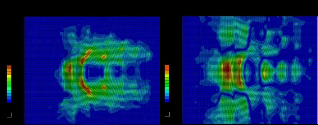
52 Table 10 compares maximum strains. Table 10. Test Data and FEM Predictions for Maximum Strains E11 E22 E12 C1 (at 3086 lbs) Tests (µε) FEM (µε) Error (%) C2 (at 3129 lbs) Tests (µε) FEM (µε) Error (%) C3 (at 3156 lbs) Tests (µε) FEM (µε) Error(%) Although the interlaminar shear strains in Figure 35 Figure 37 are in agreement, the difference in the transverse tensile strain E22 is significant. DIC contour plots for E22 show high strain concentration spots that are not predicted by the FEM. Table 10 shows that the maximum transverse tensile strain appeared to be up to 6.7 times higher in tests than in FEM predictions for coupon C1. Similar observations can be done for the other coupons. A further examination of the DIC results shows that locations of high strain concentrations seem to correspond to locations of porosity voids mentioned earlier on the different coupons. Figure 38 illustrates that correspondence for coupon C1. 42

53 Figure 38. High Strain Concentration Due to Porosity Void for Coupon C1 Porosity consists in the accidental inclusion of interfacial voids in the matrix that will result into local stress and strain concentrations. Thus, the differences between FEM and tests results could be explained by the presence of this defect which was not included in the finite element models. As shown in Figure 38, porosity voids are present in the wrinkle area with high stress gradients. Delaminations will initiate at these designated locations and at much lower loads than expected because of stress concentrations. Table 11 summarizes the results for predicted and tests data failure loads for the first three coupons. Table 11. Predicted and Tested Failure Loads for Small Wrinkle Coupons Specimens Hashin Criterion Predicted Failure Load (lbs) ITS Criterion Predicted Failure Load (lbs) Tests Failure loads (lbs) C C C
54 Failure occurs for the three coupons at loads between 3221 lbs and 3281 lbs, which is very far from what has been predicted (around 9000 lbs). We can also point out, that these failure loads are significantly lower than failure loads observed on large wrinkle coupons; contrary to what could be expected. Inclusion of models for porosity appears to be crucial in order to obtain accurate failure predictions Suggestions to Assess the Porosity Problem Modifying the Geometry Since porosity voids appear to be visible on the surface of the coupons, a possible solution could be the direct modification of the geometry in ABAQUS models to include the presence of voids. Including geometric voids will simulate stress and strain concentrations. Concentration factors are functions of the discontinuity s geometry. For a crack of length 2a and width 2b, the stress concentration factor under an applied external stress σ nom is given by Equation 7 K t = σ max σ nom = a b (7) For a hole, the stress concentration factor is classically equal to 3. The strain concentration factor equals the stress concentration factor when no plasticity or non-linear stress-strain relations are involved. For assessment of the feasibility to model porosity as holes in the geometry, a rectangular cavity was introduced in the coupon C1 at the location of the strain concentration shown in Figure 38. The cavity shown has a length of inches and a width of inches which represent approximately the dimensions and shape of the porosity void observed. 44

55 A local sub-model was built to refine the mesh around the hole as presented on Figure 39. Figure 39. Global and Submodel Mesh Details for Geometry Enclosed Void. Displacements calculated in the global model are applied as boundary conditions for the submodel. The mesh is refined around the hole to ensure a good representation of strain and stress concentrations. Figure 42 presents the contour plot for the Interlaminar Tensile Strain at 3156lbs tensile load when a small rectangular cavity is included in the model. 45

56 Figure 40. Interlaminar Tensile Strain for C1 at 3156lbs Tension with Rectangular Cavity. Figure 42 shows that the inclusion of the cavity generates strain concentrations at the edges as expected. At load 3156 lbs the maximum value for interlaminar tensile strain is 7100 µε which is about 3.2 times higher than the maximum strain level with cavity free model. However this value is still about half of the strain (1500 µε) observed in the tests. The difference could be explained by the difficulty in evaluating the geometry of the void and that other phenomena such as variable resin content and local material non-linearity or local fiber buckling are probably involved. Failure predictions based on Hashin criteria and applied to the sub-model with cavity, provided a load of 3577 lbs for failure initiation. The Interlaminar Tensile Stress criterion predicts a load of 4350 lbs. Such loads are much lower than for previous model where no porosity defect is incorporated and closer to test results presented in Table 11. However this method appears to be limited. Exact location and shape of the voids are hard to determine. Voids can also be incorporated in the thickness and not visible from the surface. This method requires important mesh refinements around the discontinuity which can rapidly 46
57 become tedious and time consuming. A method that uses a post-processing approach by including the porosity effects in the failure criterion and does not involve modifications of geometry and mesh seems to be more appropriate Modifying the Material Strength Some empirical models that take into account the effect of porosity on the strength of composite laminates have been developed in the past. Mar and Lin [18] correlated the strength of the laminate with the singularity at the crack tip. They proposed a model to express the strength σ f of a laminate as a function of the diameter 2a of an included circular notch : σ f = H 2a m (8) where H is the laminate toughness and m the order of the stress singularity at the crack tip at reinforcement/matrix interface. For carbon/epoxy laminates the authors showed that the theoretical value of m is Almeida and Nogueira Neto [19] modified the criterion for the analysis of composite laminates containing voids using ultrasonic inspection methods assuming that: σ f = H α m (9) where α is the absorption coefficient in db/mm of the considered laminate. M.L. Costa and al. [20] rewrote the criterion to adapt it to a void free laminate as: σ f = σ f0 if α α cr H α m (10) if α > α cr Where σ f0 is the fracture stress of a void free laminate and α cr is the critical value of the absorption coefficient given by: α cr = σ f0 H 1 m (11) 47
58 Such models showed good correlations with test data using 3 points bending tests [20] to evaluate Interlaminar Tensile and Shear Strength. An interesting effort would be to take into account this modification of strength properties in finite element models for the small coupons. This would consist in a simple modification in the definition of damage indexes in the subroutine. However this requires specific tests data to determine the absorption coefficient α for each coupons. Such data were not available in the framework of this thesis but could be the objective of the followup effort. 48
59 CHAPTER 3: Failure Prediction for Open Hole Carbon/epoxy Laminate 3.1 Problem Presentation The presence of circular holes in composite laminates is common for composite applications in the aerospace structures. Indeed, mechanical fasteners and rivet holes are used for various attachments. Holes in composite structures will result in local stress concentrations that will reduce the structural strength. The failure will depend strongly on the lay-up and the stacking sequence of considered laminates. The objective is to assess the capability of prediction for matrix-dominated failure onset and propagation in multi-directional lay-up carbon/epoxy laminates in presence of an open hole. FEM prediction will be compared to test data for laminates under tensile load. The specimen selected is a [45/0/-45/90] 2S carbon/epoxy IM7/8552 tape open-hole coupon. The coupon width is 1.5 inches and untabbed length is 7.5 inches, thickness is inches and a 0.25 inch-diameter hole is drilled. The specimen was submitted to tensile load and strains were monitored using the VIC technique. X-Rays pictures were taken during loading to detect the formation of cracks under the surface. Figure 41 shows the presence of matrix cracking in both 90 deg. and 45 deg. plies at ultimate failure. 49

60 Figure 41. Subsurface (X-Ray) and Surface (DIC) Images just before Ultimate Failure Tests revealed that matrix cracking starts to occur in 90 deg. plies around 4000 lbs tensile load. As the load increases, new cracks in 90 deg. plies start and propagate and first cracks in 45 deg appear around 5000 lbs. Ultimate Failure occurs by unstable opening of the 45 deg plies at 8000 lbs as shown in the Figure above. 3.2 ABAQUS Finite Element Model D Finite Element Mesh A 3D finite element model of the coupon is built using 3D stress 8 nodes elements C3D8R. Since a 3D model involves large number of Degrees of Freedom, a sub-modeling technique is used to refine locally the mesh around the hole. Figure 42 presents the global and sub-model meshes generated for the open-hole coupon. 50

61 Figure 42. Global and Sub-model 3D Finite Element Model for Open Hole Coupon ABAQUS node-based sub-modeling technique is used so that the sub-model is driven at its boundaries by nodal results for displacements calculated for the global model. Since the [45/0/-45/90]2S lay-up is symmetric, Z-symmetry boundary conditions are applies to one face of the model to reduce the number of degree of freedom. Boundary fixed displacements are applied at the lower end and uniform axial displacements with applied tensile force at the upper end. Material properties for carbon/epoxy material IM7/8552 listed on Table 4 are assigned to the ply layers with orientations defined according to the stacking sequence. Non-linear stress-strain models for interlaminar shear properties developed in and illustrated in Figure 10 are implemented. 51

62 3.2.2 Mesh Convergence The problem of mesh convergence is addressed to ensure a correct representation of stress concentrations around the hole. Convergence study is conducted only on the submodel since the large stresses gradients involved are located around the hole. The submodel ring is partitioned in eight regions. Figure 43 shows the four mesh seed parameters for the mesh generation: a determines the number of elements on the circumference, and b and c characterize the radial density of elements and t the number of elements through the thickness. Figure 43. Mesh Seed Parameters for Mesh Convergence Study No damage model is included in the convergence study but non-linear properties for interlaminar shear are implemented. An arbitrary tensile load of 1854 lbs (8250 N) is applied to the global model that drives the sub-model. The different stresses expressed in global coordinate system are considered. The influence of each mesh seed parameter is evaluated separately. Since stresses gradients are located at the hole edges and mainly in the interior ring, convergence is quickly achieved for parameter b. Table 12 compares the maximum values of the different stresses with 4 and 8 elements for mesh seed parameter b. 52
 21.35 21.34 As shown in Table 12, results with 8 elements differ to results with 4 elements by less than 0.")
63 Table 12. Influence of Parameter b in Mesh Convergence for Maximum Stresses b (nb of elements) 4 8 S11 (MPa) S22 (MPa) S33 (MPa) S12 (MPa) S13 (MPa) S23 (MPa) As shown in Table 12, results with 8 elements differ to results with 4 elements by less than 0.4% of maximal error for S 22 and thus convergence is established with 4 elements. To determine the required number of elements for parameters a, c and t, Interlaminar Stresses S 22, S 12 and S 33 are examined along a path through the thickness, as illustrated on Figure 44 for S 22. Maximum values for the considered stress are located on the path defined as illustrated. Figure 44. Stresses Plotting Path for Mesh Convergence Study 53
64 Figure 45 - Figure 53 present the influence of the different seeding parameter on the convergence for S 22, S 12 and S el 30 el 40 el 60 el Figure 45. Influence of Circumferential Parameter a for S 22 Convergence el 10 el 15 el 20 el 25 el 30 el Figure 46. Influence of Radial Parameter c for S 22 Convergence 54
65 el /ply 2 el /ply 4 el /ply 6 el /ply 8 el /ply Figure 47. Influence of Through-thickness Parameter t for S 22 Convergence el 30 el 40 el 60 el Figure 48. Influence of Circumferential Parameter a for S 12 Convergence el 10 el 15 el 20 el 25 el 30 el Figure 49. Influence of Radial Parameter c for S 12 Convergence 55
66 el /ply 2 el /ply 4 el /ply 6 el /ply 8 el /ply Figure 50. Influence of Through-thickness Parameter t for S 12 Convergence el 30 el 40 el 50 el 60 el Figure 51. Influence of Circumferential Parameter a for S 33 Convergence el 10 el 15 el 20 el 25 el 30 el Figure 52. Influence of Radial Parameter c for S 33 Convergence 56
67 el /ply 2 el /ply 4 el /ply 6 el /ply 8 el /ply 16 el /ply 32 el /ply Figure 53. Influence of Through-thickness Parameter t for S 33 Convergence Figure 45, Figure 48, and Figure 51 show that convergence is quickly achieved for the circumferential mesh seed parameter a (number of elements per quarter circumference). The three stresses reach acceptable convergence with 40 elements. Figure 46 and Figure 52 show that a fine mesh in the radial direction around the hole is necessary to calculate accurately interlaminar stresses S 22 and S 33 (convergence is quickly reached for S 12 ). 25 elements for mesh seed parameter c allow to reach convergence for S 22. However more than 30 elements are required to reach convergence for S 33 as shown in Figure 52. Figure 47, Figure 50, and Figure 53 show the influence of the number of elements per ply (through the thickness) in stress convergence. The results for stresses S 22 and S 12 show that satisfactory convergence is reached when 4 elements per plies are assigned. Figure 53 shows that for S 33 even 32 elements per plies are not enough for the results to converge. Such a refinement through the thickness results already in a very large submodel with more than 680,000 DOF and leads to the conclusion that convergence does not seem to be reasonably reachable for interlaminar stress S
68 To summarize, the mesh convergence study showed that 40 elements for mesh seed a, 6 elements for mesh seed b, 25 elements for mesh seed c and 4 elements per plythickness ensure accurate results for interlaminar tensile and shear stresses S 22 and S 12. The study also demonstrated that the finite element models developed are not able to solve the problem for transverse stress S 33 within the available computational capacity. This incapacity comes from the fact that the finite element models does not take into account the changes in the micro-structure between two layers. Stiffness properties brutally change between two group of plies which is a mathematical description and not a meaningful representation of physical reality. De Borst [21] proposed numerical corrections by introducing additional terms in continuum description to address this problem. These corrections where not considered in the framework of this thesis. Regarding failure predictions, the incapacity to have an accurate S 33 representation means that the effects of out of plane stress components should not be included in the damage model. However this should not interfere too much on the accuracy of predictions, since matrix cracking is expected to occur mainly because of in plane stress and shear concentrations. This is confirmed by the fact that maximum stress values simulated for S 22 and S 12 are about 7 times higher than the maximum value for S Failure Model Damage Initiation Criterion To predict the initiation of matrix cracking in the laminate, a criterion that takes into account the combined effect of in-plane transverse tension and shear is necessary. P. Camanho et al. [22] showed that a criterion based on fracture mechanics models of cracks in laminates leads to good correlation with experimental results. The criterion 58
69 they used is based on the Hahn [23] mixed mode criterion written as a polynomial in the stress intensity factors KI and KII at the tip of the crack: 1 g K I K Ic + g K I K Ic 2 + K II K IIc 2 1 (12) with g = G Ic G IIc where G Ic and G IIc are the fracture toughness (critical energy release rate) for mode I (tension) and mode II (shear) fracture. KIc and KIIc are the critical stress intensity factors. Using Fracture Mechanics for a slit crack, the authors showed that the criteria for linear shear stress-strain response can be expressed in term of stresses and strength as a damage index D : D = 1 g σ 22 S 22 + g σ 22 S σ 12 S (13) where S 22 and S 12 are the interlaminar tensile and shear strength. For non-linear shear behavior the last term of the criterion must be modified. Camanho and al. [22] proposed to use the Sandhu [24] assumption for failure prediction in nonlinear materials using the contribution of shear stress and shear strain to the strain energy density as : D = 1 g σ 22 S 22 + g σ 22 2 χ (γ + 12 ) S 22 χ (γ 12 u ) 1 (14) u where γ 12 is the maximum admissible shear strain defined using Equation 1 as : γ u 12 = S 12 + S 12 G 12 K 1 n (15) The strain density χ(γ 12) can be determined analytically knowing the non-linear shear behavior σ 12=σ 12(γ 12) and is defined as: γ χ γ 12 = 2 12 σ 12 dγ 0 12 (16) Using the relation given by Equation 3 extrapolated from test data, we can integrate that relation in : 59
70 γ 2 χ γ 12 = 2 G a γ b γ c γ d γ (17) We can point out that P. Camanho and al. [22] recommended to use what they call 'insitu' strength rather than the unidirectional strength properties, assessing that transverse tensile and shear strengths are higher when a ply is constrained by plies with different fiber orientations in a laminate. Strength also depends on the number of plies embedded together. The corrected strength properties listed in Table 4 take into account that consideration. The assumption that compressive stress do not contribute to damage is also done and the damage criterion [22] given by Equation 14 is finally expressed as : D = 1 g σ 22 S 22 + g σ 22 2 χ (γ S + 12 ) 22 χ (γ u 12 ) χ (γ 12 ) χ (γ u 12 ) if σ 22 0 if σ 22 < 0 (18) Damage Propagation To simulate damage propagation of matrix cracking a damage model with stiffness softening needs to be implemented in finite element models. A simple approach consists in considering that once the damage onset variable D is saturated for one element, stiffness properties in the directions of failure modes involved are dropped to zero. Thus, for matrix cracking where in plane interlaminar tensile stress and shear stress contributions are taken into account, damage propagation is insured by dropping the transverse and shear stiffness properties to zero. The described damage pattern is introduced in finite element model by using the ABAQUS user subroutine USDFLD [16] used previously to introduce non-linear material properties for shear. A field variable FV is defined as followed : 60
71 FV = 1 if D 1 0 oterwise (19) The dependence of material properties on field variable FV is described by Table 13: Table 13. Dependencies on Damage Field Variables for Matrix Cracking Material State Material properties Field variable FV No failure E 11 E 22 E 33 ν 12 ν 13 ν 23 G 12 G 13 G 23 0 Matrix failure E To be accurate, this method requires a small time increment since the damage onset variable D is evaluated from stress and strain state at the previous increment. The advantage of that method is that it is free of convergence problems that can occur when element stiffness is brutally dropped to zero. Such problems can be encountered for example when ABAQUS subroutine UMAT [16] is used to introduce the stiffness softening in the stress-strain relation. 3.3 Finite Element Analysis Results and Test Comparison Fiber Oriented Finite Element Mesh A global mesh and sub-model meshes are generated using necessary mesh refinements determined by previous convergence study. The mesh was generated as presented on Figure 42 with radially-oriented elements around the hole. A preliminary analysis showed that results were dependent of the elements orientation. Figure 54 presents the contour plot for damage variable D at a 6240 lbs tensile load. 61


72 Figure 54. Damage Contour plot at 6240lbs for 90 deg surface ply Figure 54 highlights the development of cracks in the surface 90 deg. ply. The location of cracks initiation sites at which they first occur is consistent with test results. However the direction of propagation for the cracks seems to be determined by the orientation of elements. Matrix-cracks in the 90 deg. plies are supposed to occur along the fiber direction and perpendicularly to the loading axis and not as shown. The same observation can be done for cracks developments in 45 deg. plies. This questions the validity of the model since local equilibriums of the structure are modified by cracks developments and failure load predictions become inaccurate. This dependence in element orientations and aspect ratio has been mentioned by researchers such as De Borst and Remmers [21]. ABAQUS CAE is unable to produce a structured mesh with fixed elements orientation in the presence of a hole. To address this problem, a mesh with fiber oriented elements has been developed at Georgia Institute of Technology by Senior Research Engineer 62


73 Yuri Nikishkov using a C++ code. Figure 55 presents the fiber oriented final mesh generated for the sub-model. Figure 55. Global and Sub-model Meshes for Open Hole Coupon Analysis As shown in Figure 55, elements are oriented along fiber direction for each group of plies. Surface-based tie constraints are defined between the plies to tie together the unmatched section meshes. Mesh is refined with seed biases around the hole. A coarse mesh with one element per ply and 33,240 DOF is used for the global model. No damage model is implemented for the global model analysis, but non-linear shear material properties are incorporated. The sub-model includes 4 elements per ply and about 500,000 DOF. Damage initiation and propagation models developed for matrix cracking in paragraph are included. A load of lbs (530000N) is applied to the global model. That load is applied in 2 steps. A first step with 50 increments is defined to go to 3710 lbs (16500N) tensile load where no damage should have occured according to tests results. The second step 63

74 takes 365 increments defined to apply a final load of lbs (530000N) by increasing the global load of 100N at each increment Finite Element Analysis Results and Test Data Comparison Matrix Cracking Initiation and Propagation Damage variable D is plotted to detect matrix-crack initiation and to observe its propagation when applied tensile load is increased. Figure 56 - Figure 59 present the damage variable contour plot for different load levels. Figure 56. Damage Plot for Open-Hole Coupon at 4226 lbs Tension Figure 57. Damage Plot for Open-Hole Coupon at 4991 lbs Tension 64


75 Figure 58. Damage Plot for Open Hole Coupon at 5953 lbs Tension Figure 59. Damage Plot for Open Hole Coupon at 8475 lbs Tension Figure 56 - Figure 59 show the predicted development of matrix cracking in the 90 deg. and 45 deg. plies. The first crack initiates at 4226 lbs tension in the 90 deg. plies as shown in Figure 56. At that first stage no damage has already occurred in the 45 deg. plies. Cracks in the 90-degree plies will continue to initiate and propagate until they reach the boundary of the sub-model. Cracks develop anti-symmetrically on each side of the hole. The first crack in 45 deg. plies occurs at 5032 lbs as illustrated in Figure 57. More cracks keep on developing in 45 deg. plies as the load increases but their propagations stop. At 65


76 7239 lbs a new crack starts to develop in the 45 deg. plies on each side of the hole, initiating at about 45 deg. and 225 deg. radial positions. This crack will not stop as the load increases and will propagate quickly until it reaches the sub-model model boundary at 8475lbs. This corresponds to the ultimate failure of the structure. Figure 60 compares the FEM results with ultimate crack and a picture of the test sample after ultimate failure has occurred. Figure 60. Ultimate Failure Crack for Open Hole Coupon Test Data Correlation Strains predicted by the FEM are compared to tests data as presented on Figure 61 - Figure


77 Figure 61. Surface Transverse Strain Correlation at 1st 45 deg. Crack Development Figure 62. Surface Shear Strain Correlation at 1st 45 deg. Crack Development Figure 63. Surface Transverse Strain Correlation at Ultimate Crack Development 67

78 Figure 64. Surface Shear Strain Correlation at Ultimate Crack Development FEM predictions are in agreement with tests results for interlaminar tensile and shear strains. On Figure 63 and Figure 64 some slight differences can be observed between FEM in the number and location of cracks on each side of the hole. These differences are probably due to effects of unmodeled macroscopic imperfections of the structure. But failure models developed exhibit a good capability to predict accurately the location of cracks initiation as well as their sequence of apparition. Table 14 summarizes the predicted and tested loads for different cracks developments. Table 14. Summary of Predictions and Test Data for Hole Coupon Crack developments Test data FEM +45-deg. ply cracking 5038 lbs 4991 lbs Development of ultimate crack 7313 lbs 7284 lbs Ultimate Failure 8361 lbs 8475 lbs 68
Open-hole compressive strength prediction of CFRP composite laminates
 Open-hole compressive strength prediction of CFRP composite laminates O. İnal 1, A. Ataş 2,* 1 Department of Mechanical Engineering, Balikesir University, Balikesir, 10145, Turkey, inal@balikesir.edu.tr
NUMERICAL INVESTIGATION OF DELAMINATION IN L-SHAPED CROSS-PLY COMPOSITE BRACKET
 NUMERICAL INVESTIGATION OF DELAMINATION IN L-SHAPED CROSS-PLY COMPOSITE BRACKET M.Gümüş a*, B.Gözlüklü a, D.Çöker a a Department of Aerospace Eng., METU, Ankara, Turkey *mert.gumus@metu.edu.tr Keywords:
Numerical Analysis of Composite Panels in the Post-Buckling Field taking into account Progressive Failure
 Copyright c 007 ICCES ICCES, vol.1, no.3, pp.93-98, 007 Numerical Analysis of Composite Panels in the Post-Buckling Field taking into account Progressive Failure C. Bisagni 1 Summary The research here
PROGRESSIVE DAMAGE ANALYSES OF SKIN/STRINGER DEBONDING. C. G. Dávila, P. P. Camanho, and M. F. de Moura
 PROGRESSIVE DAMAGE ANALYSES OF SKIN/STRINGER DEBONDING C. G. Dávila, P. P. Camanho, and M. F. de Moura Abstract The debonding of skin/stringer constructions is analyzed using a step-by-step simulation
INTERNATIONAL JOURNAL OF APPLIED ENGINEERING RESEARCH, DINDIGUL Volume 2, No 1, 2011
 Interlaminar failure analysis of FRP cross ply laminate with elliptical cutout Venkateswara Rao.S 1, Sd. Abdul Kalam 1, Srilakshmi.S 1, Bala Krishna Murthy.V 2 1 Mechanical Engineering Department, P. V.
Multi Disciplinary Delamination Studies In Frp Composites Using 3d Finite Element Analysis Mohan Rentala
 Multi Disciplinary Delamination Studies In Frp Composites Using 3d Finite Element Analysis Mohan Rentala Abstract: FRP laminated composites have been extensively used in Aerospace and allied industries
BIAXIAL STRENGTH INVESTIGATION OF CFRP COMPOSITE LAMINATES BY USING CRUCIFORM SPECIMENS
 BIAXIAL STRENGTH INVESTIGATION OF CFRP COMPOSITE LAMINATES BY USING CRUCIFORM SPECIMENS H. Kumazawa and T. Takatoya Airframes and Structures Group, Japan Aerospace Exploration Agency 6-13-1, Ohsawa, Mitaka,
COMPARISON OF COHESIVE ZONE MODELS USED TO PREDICT DELAMINATION INITIATED FROM FREE-EDGES : VALIDATION AGAINST EXPERIMENTAL RESULTS
 COMPARISON OF COHESIVE ZONE MODELS USED TO PREDICT DELAMINATION INITIATED FROM FREE-EDGES : VALIDATION AGAINST EXPERIMENTAL RESULTS A. Uguen 1, L. Zubillaga 2, A. Turon 3, N. Carrère 1 1 Laboratoire Brestois
SKIN-STRINGER DEBONDING AND DELAMINATION ANALYSIS IN COMPOSITE STIFFENED SHELLS
 SKIN-STRINER DEBONDIN AND DELAMINATION ANALYSIS IN COMPOSITE STIFFENED SHELLS R. Rikards, K. Kalnins & O. Ozolinsh Institute of Materials and Structures, Riga Technical University, Riga 1658, Latvia ABSTRACT
THREE DIMENSIONAL STRESS ANALYSIS OF THE T BOLT JOINT
 THREE DIMENSIONAL STRESS ANALYSIS OF THE T BOLT JOINT Víctor Martínez 1, Alfredo Güemes 2, Norbert Blanco 1, Josep Costa 1 1 Escola Politècnica Superior. Universitat de Girona. Girona, Spain (17071) 2
Computational Analysis for Composites
 Computational Analysis for Composites Professor Johann Sienz and Dr. Tony Murmu Swansea University July, 011 The topics covered include: OUTLINE Overview of composites and their applications Micromechanics
THE ROLE OF DELAMINATION IN NOTCHED AND UNNOTCHED TENSILE STRENGTH
 THE ROLE OF DELAMINATION IN NOTCHED AND UNNOTCHED TENSILE STRENGTH M. R. Wisnom University of Bristol Advanced Composites Centre for Innovation and Science University Walk, Bristol BS8 1TR, UK M.Wisnom@bristol.ac.uk
PREDICTION OF OUT-OF-PLANE FAILURE MODES IN CFRP
 PREDICTION OF OUT-OF-PLANE FAILURE MODES IN CFRP R. R. Pinto 1, P. P. Camanho 2 1 INEGI - Instituto de Engenharia Mecanica e Gestao Industrial, Rua Dr. Roberto Frias, 4200-465, Porto, Portugal 2 DEMec,
ASSESSING INTERLAMINAR SHEAR STRESS-STRAIN CURVES IN TAPE COMPOSITES BASED ON THE FLAT-PLATE TORSION METHOD GARY STEVEN GROHMAN JR
 ASSESSING INTERLAMINAR SHEAR STRESS-STRAIN CURVES IN TAPE COMPOSITES BASED ON THE FLAT-PLATE TORSION METHOD by GARY STEVEN GROHMAN JR Presented to the Faculty of the Graduate School of The University of
DAMAGE SIMULATION OF CFRP LAMINATES UNDER HIGH VELOCITY PROJECTILE IMPACT
 18 TH INTERNATIONAL CONFERENCE ON COMPOSITE MATERIALS DAMAGE SIMULATION OF CFRP LAMINATES UNDER HIGH VELOCITY PROJECTILE IMPACT A. Yoshimura 1*, T. Okabe, M. Yamada 3, T. Ogasawara 1, Y. Tanabe 3 1 Advanced
ISSN: ISO 9001:2008 Certified International Journal of Engineering Science and Innovative Technology (IJESIT) Volume 2, Issue 4, July 2013
 Volume 2, Issue 4, July 2013") Delamination Studies in Fibre-Reinforced Polymer Composites K.Kantha Rao, Dr P. Shailesh, K. Vijay Kumar 1 Associate Professor, Narasimha Reddy Engineering College Hyderabad. 2 Professor, St. Peter s Engineering
Delamination Studies in Fibre-Reinforced Polymer Composites K.Kantha Rao, Dr P. Shailesh, K. Vijay Kumar 1 Associate Professor, Narasimha Reddy Engineering College Hyderabad. 2 Professor, St. Peter s Engineering
Modelling the nonlinear shear stress-strain response of glass fibrereinforced composites. Part II: Model development and finite element simulations
 Modelling the nonlinear shear stress-strain response of glass fibrereinforced composites. Part II: Model development and finite element simulations W. Van Paepegem *, I. De Baere and J. Degrieck Ghent
INITIATION AND PROPAGATION OF FIBER FAILURE IN COMPOSITE LAMINATES
 THE 19 TH INTERNATIONAL CONFERENCE ON COMPOSITE MATERIALS INITIATION AND PROPAGATION OF FIBER FAILURE IN COMPOSITE LAMINATES E. Iarve 1,2*, D. Mollenhauer 1, T. Breitzman 1, K. Hoos 2, M. Swindeman 2 1
Finite element modelling of infinitely wide Angle-ply FRP. laminates
 www.ijaser.com 2012 by the authors Licensee IJASER- Under Creative Commons License 3.0 editorial@ijaser.com Research article ISSN 2277 9442 Finite element modelling of infinitely wide Angle-ply FRP laminates
Numerical Analysis of Delamination Behavior in Laminated Composite with Double Delaminations Embedded in Different Depth Positions
 Numerical Analysis of Delamination Behavior in Laminated Composite with Double Delaminations Embedded in Different Depth Positions Numerical Analysis of Delamination Behavior in Laminated Composite with
A RESEARCH ON NONLINEAR STABILITY AND FAILURE OF THIN- WALLED COMPOSITE COLUMNS WITH OPEN CROSS-SECTION
 A RESEARCH ON NONLINEAR STABILITY AND FAILURE OF THIN- WALLED COMPOSITE COLUMNS WITH OPEN CROSS-SECTION H. Debski a*, J. Bienias b, P. Jakubczak b a Faculty of Mechanical Engineering, Department of Machine
Composite Damage Material Modeling for Crash Simulation: MAT54 & the Efforts of the CMH-17 Numerical Round Robin
 Composite Damage Material Modeling for Crash Simulation: MAT54 & the Efforts of the CMH-17 Numerical Round Robin 2014 Technical Review Bonnie Wade (UW) Prof. Paolo Feraboli AMTAS (JAMS) Crashworthiness
THE MUTUAL EFFECTS OF SHEAR AND TRANSVERSE DAMAGE IN POLYMERIC COMPOSITES
 THE 19 TH INTERNATIONAL CONFERENCE ON COMPOSITE MATERIALS THE MUTUAL EFFECTS OF SHEAR AND TRANSVERSE DAMAGE IN POLYMERIC COMPOSITES L.V. Smith 1 *, M. Salavatian 1 1 School of Mechanical and Materials
TESTING AND ANALYSIS OF COMPOSITE SKIN/STRINGER DEBONDING UNDER MULTI-AXIAL LOADING.
 TESTING AND ANALYSIS OF COMPOSITE SKIN/STRINGER DEBONDING UNDER MULTI-AXIAL LOADING. Ronald Krueger*, Michael K. Cvitkovich*, T. Kevin O'Brien**, and Pierre J. Minguet*** * National Research Council Research
Numerical simulation of delamination onset and growth in laminated composites
 Numerical simulation of delamination onset and growth in laminated composites G. Wimmer, C. Schuecker, H.E. Pettermann Austrian Aeronautics Research (AAR) / Network for Materials and Engineering at the
Fracture Behaviour of FRP Cross-Ply Laminate With Embedded Delamination Subjected To Transverse Load
 Fracture Behaviour of FRP Cross-Ply Laminate With Embedded Delamination Subjected To Transverse Load Sriram Chintapalli 1, S.Srilakshmi 1 1 Dept. of Mech. Engg., P. V. P. Siddhartha Institute of Technology.
A STRUCTURE DESIGN OF CFRP REAR PRESSURE BULKHEAD WITHOUT STIFFENERS
 Xi an, 2-25 th August 217 A STRUCTURE DESIGN OF CFRP REAR PRESSURE BULKHEAD WITHOUT STIFFENERS LI Zhongyang 1, LI Dong 2 Mailbox72-35, Yanliang District, Xian, China, Email: zhongyangli@live.com Keywords:
5. STRESS CONCENTRATIONS. and strains in shafts apply only to solid and hollow circular shafts while they are in the
 5. STRESS CONCENTRATIONS So far in this thesis, most of the formulas we have seen to calculate the stresses and strains in shafts apply only to solid and hollow circular shafts while they are in the elastic
MECE 3321 MECHANICS OF SOLIDS CHAPTER 3
 MECE 3321 MECHANICS OF SOLIDS CHAPTER 3 Samantha Ramirez TENSION AND COMPRESSION TESTS Tension and compression tests are used primarily to determine the relationship between σ avg and ε avg in any material.
BEARING STRENGTH ASSESSMENT OF COMPOSITE MATERIAL THROUGH NUMERICAL MODELS
 BEARING STRENGTH ASSESSMENT OF COMPOSITE MATERIAL THROUGH NUMERICAL MODELS Euler S. Dias*, Carlos A. Cimini Jr.* * Federal University of Minas Gerais, Dept. of Structural Engineering, Belo Horizonte -
FLOATING NODE METHOD AND VIRTUAL CRACK CLOSURE TECHNIQUE FOR MODELING MATRIX CRACKING- DELAMINATION MIGRATION
 THE 19 TH INTERNATIONAL CONFERENCE ON COMPOSITE MATERIALS FLOATING NODE METHOD AND VIRTUAL CRACK CLOSURE TECHNIQUE FOR MODELING MATRIX CRACKING- DELAMINATION MIGRATION N. V. De Carvalho 1*, B. Y. Chen
SIZE EFFECTS IN THE COMPRESSIVE CRUSHING OF HONEYCOMBS
 43rd AIAA/ASME/ASCE/AHS/ASC Structures, Structural Dynamics, and Materials Con 22-25 April 2002, Denver, Colorado SIZE EFFECTS IN THE COMPRESSIVE CRUSHING OF HONEYCOMBS Erik C. Mellquistand Anthony M.
Prediction of Delamination Growth Behavior in a Carbon Fiber Composite Laminate Subjected to Constant Amplitude Compression-Compression Fatigue Loads
 Prediction of Delamination Growth Behavior in a Carbon Fiber Composite Laminate Subjected to Constant Amplitude Compression-Compression Fatigue Loads J. Raju 1*, D.S. Sreedhar 2, & C.M. Manjunatha 1 1
Generic Strategies to Implement Material Grading in Finite Element Methods for Isotropic and Anisotropic Materials
 University of Nebraska - Lincoln DigitalCommons@University of Nebraska - Lincoln Engineering Mechanics Dissertations & Theses Mechanical & Materials Engineering, Department of Winter 12-9-2011 Generic
Effects of Resin and Fabric Structure
 Fatigue of Wind Blade Laminates: Effects of Resin and Fabric Structure Details David Miller, Daniel D. Samborsky and John F. Mandell Montana State t University it MCARE 2012 Outline Overview of MSU Fatigue
MECHANICAL FAILURE OF A COMPOSITE HELICOPTER STRUCTURE UNDER STATIC LOADING
 MECHANICAL FAILURE OF A COMPOSITE HELICOPTER STRUCTURE UNDER STATIC LOADING Steven Roy, Larry Lessard Dept. of Mechanical Engineering, McGill University, Montreal, Québec, Canada ABSTRACT The design and
Prediction of Elastic Constants on 3D Four-directional Braided
 Prediction of Elastic Constants on 3D Four-directional Braided Composites Prediction of Elastic Constants on 3D Four-directional Braided Composites Liang Dao Zhou 1,2,* and Zhuo Zhuang 1 1 School of Aerospace,
Crashworthiness of composite structures: Experiment and Simulation
 Crashworthiness of composite structures: Experiment and Simulation Francesco Deleo, Bonnie Wade and Prof. Paolo Feraboli (UW) Dr. Mostafa Rassaian (Boeing R&T) JAMS 2010 The Joint Advanced Materials and
COMPRESSIVE BEHAVIOR OF IMPACT DAMAGED COMPOSITE LAMINATES
 16 TH INTERNATIONAL CONFERENCE ON COMPOSITE MATERIALS COMPRESSIVE BEHAVIOR OF IMPACT DAMAGED COMPOSITE LAMINATES Hiroshi Suemasu*, Wataru Sasaki**, Yuuichiro Aoki***, Takashi Ishikawa**** *Department of
EFFECT OF THERMAL FATIGUE ON INTRALAMINAR CRACKING IN LAMINATES LOADED IN TENSION
 EFFECT OF THERMAL FATIGUE ON INTRALAMINAR CRACKING IN LAMINATES LOADED IN TENSION J.Varna and R.Joffe Dept of Applied Physics and Mechanical Engineering Lulea University of Technology, SE 97187, Lulea,
High Fidelity Failure Analysis for A Composite Fuselage Section 1
 High Fidelity Failure Analysis for A Composite Fuselage Section 1 Jian Li Engineer/Scientist, The Boeing Company Mesa, Arizona Jian.Li@Boeing.com Carlos G. Dávila Aerospace Engineer, NASA Langley Research
LS-DYNA MAT54 for simulating composite crash energy absorption
 LS-DYNA MAT54 for simulating composite crash energy absorption Bonnie Wade and Paolo Feraboli (UW) Mostafa Rassaian (Boeing BR&T) JAMS 2011 The Joint Advanced Materials and Structures Center of Excellence
Stress Intensity Factor Determination of Multiple Straight and Oblique Cracks in Double Cover Butt Riveted Joint
 ISSN (Online) : 2319-8753 ISSN (Print) : 2347-671 International Journal of Innovative Research in Science, Engineering and Technology Volume 3, Special Issue 3, March 214 214 International Conference on
Durability of bonded aircraft structure. AMTAS Fall 2016 meeting October 27 th 2016 Seattle, WA
 Durability of bonded aircraft structure AMTAS Fall 216 meeting October 27 th 216 Seattle, WA Durability of Bonded Aircraft Structure Motivation and Key Issues: Adhesive bonding is a key path towards reduced
Size Effects In the Crushing of Honeycomb Structures
 45th AIAA/ASME/ASCE/AHS/ASC Structures, Structural Dynamics & Materials Conference 19-22 April 2004, Palm Springs, California AIAA 2004-1640 Size Effects In the Crushing of Honeycomb Structures Erik C.
NUMERICAL MODELLING OF COMPOSITE PIN- JOINTS AND EXPERIMENTAL VALIDATION
 NUMERICAL MODELLING OF COMPOSITE PIN- JOINTS AND EXPERIMENTAL VALIDATION Fabrice PIERRON*, François CERISIER*, and Michel GRÉDIAC** * SMS/ Département Mécanique et Matériaux, École Nationale Supérieure
Fracture Mechanics, Damage and Fatigue: Composites
 University of Liège Aerospace & Mechanical Engineering Fracture Mechanics, Damage and Fatigue: Composites Ludovic Noels Computational & Multiscale Mechanics of Materials CM3 http://www.ltas-cm3.ulg.ac.be/
University of Bristol - Explore Bristol Research. Early version, also known as pre-print
 Hallett, S. R., & Wisnom, M. R. (2006). Numerical investigation of progressive damage and the effect of layup in notched tensile tests. Journal of Composite Materials, 40 (14), 1229-1245. DOI: 10.1177/0021998305057432
Evaluation of in-plane orthotropic elastic constants of paper and paperboard
 Evaluation of in-plane orthotropic elastic constants of paper and paperboard T. Yokoyama and K. Nakai Department of Mechanical Engineering, Okayama University of Science - Ridai-cho, Okayama 7-5, Japan
TABLE OF CONTENTS. Mechanics of Composite Materials, Second Edition Autar K Kaw University of South Florida, Tampa, USA
 Mechanics of Composite Materials, Second Edition Autar K Kaw University of South Florida, Tampa, USA TABLE OF CONTENTS 1. INTRODUCTION TO COMPOSITE MATERIALS 1.1 Introduction... 1.2 Classification... 1.2.1
Strength of GRP-laminates with multiple fragment damages
 Strength of GRP-laminates with multiple fragment damages S. Kazemahvazi, J. Kiele, D. Zenkert Kungliga Tekniska Högskolan, KTH 100 44 Stockholm, Sweden sohrabk@kth.se SUMMARY The strength of glass fibre
Impact and Crash Modeling of Composite Structures: A Challenge for Damage Mechanics
 Impact and Crash Modeling of Composite Structures: A Challenge for Damage Mechanics Dr. A. Johnson DLR Dr. A. K. Pickett ESI GmbH EURO-PAM 99 Impact and Crash Modelling of Composite Structures: A Challenge
MODELING OF THE BEHAVIOR OF WOVEN LAMINATED COMPOSITES UNTIL RUPTURE
 MODELING OF THE BEHAVIOR OF WOVEN LAMINATED COMPOSITES UNTIL RUPTURE Jean Paul Charles, Christian Hochard,3, Pierre Antoine Aubourg,3 Eurocopter, 375 Marignane cedex, France Unimeca, 6 rue J. Curie, 3453
PLY LEVEL UNCERTAINTY EFFECTS ON FAILURE OF COMPOSITE
 7th European Workshop on Structural Health Monitoring July 8-11, 2014. La Cité, Nantes, France More Info at Open Access Database www.ndt.net/?id=17206 PLY LEVEL UNCERTAINTY EFFECTS ON FAILURE OF COMPOSITE
Multiscale Approach to Damage Analysis of Laminated Composite Structures
 Multiscale Approach to Damage Analysis of Laminated Composite Structures D. Ivančević and I. Smojver Department of Aeronautical Engineering, Faculty of Mechanical Engineering and Naval Architecture, University
Fig. 1. Different locus of failure and crack trajectories observed in mode I testing of adhesively bonded double cantilever beam (DCB) specimens.
 specimens.") a). Cohesive Failure b). Interfacial Failure c). Oscillatory Failure d). Alternating Failure Fig. 1. Different locus of failure and crack trajectories observed in mode I testing of adhesively bonded double
a). Cohesive Failure b). Interfacial Failure c). Oscillatory Failure d). Alternating Failure Fig. 1. Different locus of failure and crack trajectories observed in mode I testing of adhesively bonded double
Mechanical Properties of Materials
 Mechanical Properties of Materials Strains Material Model Stresses Learning objectives Understand the qualitative and quantitative description of mechanical properties of materials. Learn the logic of
CHARACTERIZATION, ANALYSIS AND PREDICTION OF DELAMINATION IN COMPOSITES USING FRACTURE MECHANICS
 Oral Reference Number: ICF100942OR CHARACTERIZATION, ANALYSIS AND PREDICTION OF DELAMINATION IN COMPOSITES USING FRACTURE MECHANICS T. Kevin O Brien U.S. Army Research Laboratory Vehicle Technology Directorate
FINITE ELEMENT ANALYSIS OF COMPOSITE MATERIALS
 FINITE ELEMENT ANALYSIS OF COMPOSITE MATERIALS Ever J. Barbero Department of Mechanical and Aerospace Engineering West Virginia University USA CRC Press Taylor &.Francis Group Boca Raton London New York
Tensile behaviour of anti-symmetric CFRP composite
 Available online at www.sciencedirect.com Procedia Engineering 1 (211) 1865 187 ICM11 Tensile behaviour of anti-symmetric CFRP composite K. J. Wong a,b, *, X. J. Gong a, S. Aivazzadeh a, M. N. Tamin b
The science of elasticity
 The science of elasticity In 1676 Hooke realized that 1.Every kind of solid changes shape when a mechanical force acts on it. 2.It is this change of shape which enables the solid to supply the reaction
RELIABILITY ANALYSIS IN BOLTED COMPOSITE JOINTS WITH SHIMMING MATERIAL
 25 TH INTERNATIONAL CONGRESS OF THE AERONAUTICAL SCIENCES RELIABILITY ANALYSIS IN BOLTED COMPOSITE JOINTS WITH SHIMMING MATERIAL P. Caracciolo, G. Kuhlmann AIRBUS-Germany e-mail: paola.caracciolo@airbus.com
Material Characterization of Carbon Fiber Reinforced Polymer Laminate Using Virtual Fields Method
 Proceedings of ICTACEM 014 International Conference on Theoretical, Applied, Computational and Experimental Mechanics December 9-31, 014, IIT Kharagpur, India ICTACEM-014/39 Material Characterization of
Lab Exercise #5: Tension and Bending with Strain Gages
 Lab Exercise #5: Tension and Bending with Strain Gages Pre-lab assignment: Yes No Goals: 1. To evaluate tension and bending stress models and Hooke s Law. a. σ = Mc/I and σ = P/A 2. To determine material
REPRESENTING MATRIX CRACKS THROUGH DECOMPOSITION OF THE DEFORMATION GRADIENT TENSOR IN CONTINUUM DAMAGE MECHANICS METHODS
 20 th International Conference on Composite Materials Copenhagen, 19-24 th July 2015 REPRESENTING MATRIX CRACKS THROUGH DECOMPOSITION OF THE DEFORMATION GRADIENT TENSOR IN CONTINUUM DAMAGE MECHANICS METHODS
USE OF DIGITAL IMAGE CORRELATION TO OBTAIN MATERIAL MODEL PARAMETERS FOR COMPOSITES
 USE OF DIGITAL IMAGE CORRELATION TO OBTAIN MATERIAL MODEL PARAMETERS FOR COMPOSITES Brian Croop, Hubert Lobo (DatapointLabs, USA). Presenter: Hubert Lobo, President SUMMARY The development of material
*Corresponding author: Keywords: Finite-element analysis; Multiscale modelling; Onset theory; Dilatational strain invariant.
 18 TH INTERNATIONAL CONFERENCE ON COMPOSITE MATERIALS MICROMECHANICAL MODELLING OF TEST SPECIMENS FOR ONSET OF DILATATIONAL DAMAGE OF POLYMER MATRIX IN COMPOSITE MATERIALS T. D. Tran 1, D. Kelly 1*, G.
A SELF-INDICATING MODE I INTERLAMINAR TOUGHNESS TEST
 A SELF-INDICATING MODE I INTERLAMINAR TOUGHNESS TEST P. Robinson The Composites Centre, Department of Aeronautics, Imperial College London South Kensington, London, SW7 2AZ, UK p.robinson@imperial.ac.uk
Application of fracture mechanics-based methodologies for failure predictions in composite structures
 Application of fracture mechanics-based methodologies for failure predictions in composite structures Zoltan Mikulik a, B. Gangadhara Prusty a, Rodney S. Thomson b, Donald W. Kelly a,* a School of Mechanical
Failure analysis of serial pinned joints in composite materials
 Indian Journal of Engineering & Materials Sciences Vol. 18, April 2011, pp. 102-110 Failure analysis of serial pinned joints in composite materials Alaattin Aktaş* Department of Mechanical Engineering,
Dynamic Response Of Laminated Composite Shells Subjected To Impulsive Loads
 IOSR Journal of Mechanical and Civil Engineering (IOSR-JMCE) e-issn: 2278-1684,p-ISSN: 2320-334X, Volume 14, Issue 3 Ver. I (May. - June. 2017), PP 108-123 www.iosrjournals.org Dynamic Response Of Laminated
DAMAGE MECHANICS MODEL FOR OFF-AXIS FATIGUE BEHAVIOR OF UNIDIRECTIONAL CARBON FIBER-REINFORCED COMPOSITES AT ROOM AND HIGH TEMPERATURES
 DAMAGE MECHANICS MODEL FOR OFF-AXIS FATIGUE BEHAVIOR OF UNIDIRECTIONAL CARBON FIBER-REINFORCED COMPOSITES AT ROOM AND HIGH TEMPERATURES M. Kawai Institute of Engineering Mechanics University of Tsukuba,
Non-conventional Glass fiber NCF composites with thermoset and thermoplastic matrices. F Talence, France Le Cheylard, France
 20 th International Conference on Composite Materials Copenhagen, 19-24th July 2015 Non-conventional Glass fiber NCF composites with thermoset and thermoplastic matrices. Thierry Lorriot 1, Jalal El Yagoubi
EMA 3702 Mechanics & Materials Science (Mechanics of Materials) Chapter 2 Stress & Strain - Axial Loading
 Chapter 2 Stress & Strain - Axial Loading") MA 3702 Mechanics & Materials Science (Mechanics of Materials) Chapter 2 Stress & Strain - Axial Loading MA 3702 Mechanics & Materials Science Zhe Cheng (2018) 2 Stress & Strain - Axial Loading Statics
MA 3702 Mechanics & Materials Science (Mechanics of Materials) Chapter 2 Stress & Strain - Axial Loading MA 3702 Mechanics & Materials Science Zhe Cheng (2018) 2 Stress & Strain - Axial Loading Statics
Coupling of plasticity and damage in glass fibre reinforced polymer composites
 EPJ Web of Conferences 6, 48 1) DOI: 1.151/epjconf/1648 c Owned by the authors, published by EDP Sciences, 1 Coupling of plasticity and damage in glass fibre reinforced polymer composites R. Kvale Joki
Interlaminar fracture characterization in composite materials by using acoustic emission
 5th International Symposium on NDT in Aerospace, 13-15th November 2013, Singapore Interlaminar fracture characterization in composite materials by using acoustic emission Ian SILVERSIDES 1, Ahmed MASLOUHI
MECHANICS OF MATERIALS
 CHATR Stress MCHANICS OF MATRIALS and Strain Axial Loading Stress & Strain: Axial Loading Suitability of a structure or machine may depend on the deformations in the structure as well as the stresses induced
Mechanical Engineering Ph.D. Preliminary Qualifying Examination Solid Mechanics February 25, 2002
 student personal identification (ID) number on each sheet. Do not write your name on any sheet. #1. A homogeneous, isotropic, linear elastic bar has rectangular cross sectional area A, modulus of elasticity
EXPERIMENTAL CHARACTERIZATION AND COHESIVE LAWS FOR DELAMINATION OF OFF-AXIS GFRP LAMINATES
 20 th International Conference on Composite Materials Copenhagen, 19-24 th July 2015 EXPERIMENTAL CHARACTERIZATION AND COHESIVE LAWS FOR DELAMINATION OF OFF-AXIS GFRP LAMINATES Esben Lindgaard 1 and Brian
An orthotropic damage model for crash simulation of composites
 High Performance Structures and Materials III 511 An orthotropic damage model for crash simulation of composites W. Wang 1, F. H. M. Swartjes 1 & M. D. Gan 1 BU Automotive Centre of Lightweight Structures
Materials and Structures. Indian Institute of Technology Kanpur
 Introduction to Composite Materials and Structures Nachiketa Tiwari Indian Institute of Technology Kanpur Lecture 16 Behavior of Unidirectional Composites Lecture Overview Mt Material ilaxes in unidirectional
SSRG International Journal of Mechanical Engineering (SSRG-IJME) volume1 issue5 September 2014
 volume1 issue5 September 2014") Finite Element Modeling for Delamination Analysis of Double Cantilever Beam Specimen Mohammed Waseem H.S. 1, Kiran Kumar N. 2 1 Post Graduate Student, 2 Asst. Professor Dept. of Mechanical Engineering,
Finite Element Modeling for Delamination Analysis of Double Cantilever Beam Specimen Mohammed Waseem H.S. 1, Kiran Kumar N. 2 1 Post Graduate Student, 2 Asst. Professor Dept. of Mechanical Engineering,
Samantha Ramirez, MSE. Stress. The intensity of the internal force acting on a specific plane (area) passing through a point. F 2
 passing through a point. F 2") Samantha Ramirez, MSE Stress The intensity of the internal force acting on a specific plane (area) passing through a point. Δ ΔA Δ z Δ 1 2 ΔA Δ x Δ y ΔA is an infinitesimal size area with a uniform force
Samantha Ramirez, MSE Stress The intensity of the internal force acting on a specific plane (area) passing through a point. Δ ΔA Δ z Δ 1 2 ΔA Δ x Δ y ΔA is an infinitesimal size area with a uniform force
Standard Test Method for Open Hole Tensile Strength of Polymer Matrix Composite Laminates 1
 This document is not an ASTM standard and is intended only to provide the user of an ASTM standard an indication of what changes have been made to the previous version. Because it may not be technically
3.2.2 principal material coordinate system, n a coordinate system with axes that are normal to the planes of symmetry inherent to a material
 Designation: Standard Test Method for Open Hole Tensile Strength of Polymer Matrix Composite Laminates 1 This standard is issued under the fixed designation D 5766/D 5766M; the number immediately following
Influence of the filament winding process variables on the mechanical behavior of a composite pressure vessel
 Influence of the filament winding process variables on the mechanical behavior of a composite pressure vessel G. Vargas 1 & A. Miravete 2 1 Universidad Pontificia Bolivariana, Facultad de Ingeniería Mecánica,
FINITE ELEMENT AND EXPERIMENTAL STUDY OF NOVEL CONCEPT OF 3D FIBRE CELL STRUCTURE
 FINITE ELEMENT AND EXPERIMENTAL STUDY OF NOVEL CONCEPT OF 3D FIBRE CELL STRUCTURE M. Růžička, V. Kulíšek 2, J. Had, O. Prejzek Department of Mechanics, Biomechanics and Mechatronics, Faculty of Mechanical
UNCONVENTIONAL FINITE ELEMENT MODELS FOR NONLINEAR ANALYSIS OF BEAMS AND PLATES
 UNCONVENTIONAL FINITE ELEMENT MODELS FOR NONLINEAR ANALYSIS OF BEAMS AND PLATES A Thesis by WOORAM KIM Submitted to the Office of Graduate Studies of Texas A&M University in partial fulfillment of the
RUNWAY DEBRIS IMPACT ON GENERIC COMPOSITE TURBOFAN BLADE MULTISCALE PROGRESSIVE FAILURE ANALYSIS
 RUNWAY DEBRIS IMPACT ON GENERIC COMPOSITE TURBOFAN BLADE MULTISCALE PROGRESSIVE FAILURE ANALYSIS Gong Huiling 1 Frank Abdi 2 Marc VillàMontero 2 Cody Godines 2 1 MVT Group Inc, Shanghai, China 2 Alpha
Development of a Progressive Failure Model for Notched Woven Composite Laminates. Daniel Christopher Munden
 Development of a Progressive Failure Model for Notched Woven Composite Laminates Daniel Christopher Munden Thesis submitted to the faculty of the Virginia Polytechnic Institute and State University in
An investigation of the mechanical behaviour of carbon epoxy cross ply cruciform specimens under biaxial loading
 An investigation of the mechanical behaviour of carbon epoxy cross ply cruciform specimens under biaxial loading A. Makris, C. Ramault, D. Van Hemelrijck Department of Mechanics of Materials and Constructions,
An integrated approach to the design of high performance carbon fibre reinforced risers - from micro to macro - scale
 An integrated approach to the design of high performance carbon fibre reinforced risers - from micro to macro - scale Angelos Mintzas 1, Steve Hatton 1, Sarinova Simandjuntak 2, Andrew Little 2, Zhongyi
American Society for Testing and Materials (ASTM) Standards. Mechanical Testing of Composites and their Constituents
 Standards. Mechanical Testing of Composites and their Constituents") Mechanical Testing of Composites and their Constituents American Society for Testing and Materials (ASTM) Standards Tests done to determine intrinsic material properties such as modulus and strength for
Mechanical Testing of Composites and their Constituents American Society for Testing and Materials (ASTM) Standards Tests done to determine intrinsic material properties such as modulus and strength for
NUMERICAL FEM ANALYSIS FOR THE PART OF COMPOSITE HELICOPTER ROTOR BLADE
 Journal of KONES Powertrain and Transport, Vol. 19, No. 1 2012 NUMERICAL FEM ANALYSIS FOR THE PART OF COMPOSITE HELICOPTER ROTOR BLADE Hubert D bski Lublin University of Technology, Department of Machine
DEVELOPMENT OF TEST GUIDANCE FOR COMPACT TENSION FRACTURE TOUGHNESS SPECIMENS CONTAINING NOTCHES INSTEAD OF FATIGUE PRE-CRACKS
 Transactions, SMiRT-23 Division II, Paper ID 287 Fracture Mechanics and Structural Integrity DEVELOPMENT OF TEST GUIDANCE FOR COMPACT TENSION FRACTURE TOUGHNESS SPECIMENS CONTAINING NOTCHES INSTEAD OF
Unified Quiz M4 May 7, 2008 M - PORTION
 9:00-10: 00 (last four digits) 32-141 Unified Quiz M4 May 7, 2008 M - PORTION Put the last four digits of your MIT ID # on each page of the exam. Read all questions carefully. Do all work on that question
SIMULATION OF PROGRESSIVE FAILURE PREDICTION OF FILAMENT WOUND COMPOSITE TUBES SUBJECTED TO MULTIPLE LOADING WITH MEMBRANE-FLEXION COUPLING EFFECTS
 VOL. 5, NO. 4, APRIL 010 ISSN 1819-6608 006-010 Asian Research Publishing Network (ARPN). All rights reserved. SIMULATION OF PROGRESSIVE FAILURE PREDICTION OF FILAMENT WOUND COMPOSITE TUBES SUBJECTED TO
EFFECT OF ELLIPTIC OR CIRCULAR HOLES ON THE STRESS DISTRIBUTION IN PLATES
 EFFECT OF ELLIPTIC OR CIRCULAR HOLES ON THE STRESS DISTRIBUTION IN PLATES OF WOOD OR PLYWOOD CONSIDERED AS ORTHOTROPIC MATERIALS Information Revied and Reaffirmed March 1956 No. 1510 EFFECT OF ELLIPTIC
RATE-DEPENDENT OFF-AXIS COMPRESSIVE STRENGTH OF A UNIDIRECTIONAL CARBON/EPOXY LAMINATE AT HIGH TEMPERATURE
 16 TH INTERNATIONAL CONFERENCE ON COMPOSITE MATERIALS RATE-DEPENDENT OFF-AXIS COMPRESSIVE STRENGTH OF A UNIDIRECTIONAL CARBON/EPOXY LAMINATE AT HIGH TEMPERATURE Masamichi KAWAI *, Satoru SAITO **, Jian-Qi
A FINITE ELEMENT MODEL FOR THE ANALYSIS OF DELAMINATIONS IN FRP SHELLS
 TRENDS IN COMPUTATIONAL STRUCTURAL MECHANICS W.A. Wall, K.-U. Bletzinger and K. Schweizerhof (Eds.) c CIMNE, Barcelona, Spain 2001 A FINITE ELEMENT MODEL FOR THE ANALYSIS OF DELAMINATIONS IN FRP SHELLS