gap trans inc n=1 z Jackson 7.3 Homework Problem Solution Dr. Christopher S. Baird University of Massachusetts Lowell
|
|
|
- Gillian Collins
- 6 years ago
- Views:
Transcription
1 Jackson 7.3 Homework Problem Solution Dr. Christopher S. Baird University of Massachusetts Lowell PROBLEM: Two plane semi-infinite slabs of the same uniform, isotropic, nonpermeable, lossless dielectric with index of refraction n are parallel and separated by an air gap (n ) of width d. A plane electromagnetic wave of frequency ω in free space is incident on the gap from one of the slabs with angle of incidence i. For linear polarization both parallel to and perpendicular to the plane of incidence, (a) calculate the ratio of power transmitted into the second slab to the incident power and the ratio of reflected to incident power; (b) for i greater than the critical angle for total internal reflection, sketch the ratio of transmitted power to incident power as a function of d measured in units of wavelength in the gap. SOLUTION: This problem is very interesting because it contains the fundamental physics behind etalons, interferometers, and Fabry-Perot cavities. There are three separate regions of uniform material, so we set up different electric fields in each and then relate them using boundary conditions. Because the incident wave is a plane wave, and the interfaces are flat, we assume the fields in all regions take on the form of plane waves. Let us call the incident material region inc, the air gap region gap, and the last slab region trans. Place the interface between the incident slab and the gap at z 0 and the other interface at z d. In the incident slab, there is a forward-going wave (the incident wave) and a backward-going wave (the sum of all reflected waves). In the gap there is also a forward-going wave (the sum of all forward-reflected waves) and a backward-going wave (the sum of all backwardreflected waves). In the transmitted slab there is only a forward-going wave (the sum of all transmitted waves). Note that all materials are lossless so that n and k are real-valued. The waves are all assumed to have linear polarization: E inc ϵ 0 E 0 e i (n c ω k x ω t ) + ϵ E e i (n c ω k x ω t ) E gap ϵ 2 e i ( c ω 2 k 2 x ω 2 t ) + ϵ3 E 3 e i ( c ω 3 k 3 x ω 3 t) k inc gap k k 2 k 3 k 4 trans E trans ϵ 4 E 4 e i ( n c ω 4 k 4 (x d) ω 4 t ) Note that the transmitted field in the last slab was shifted a distance d in the z direction to account for the fact that it is created at z d and not z 0, despite being defined as relative to z 0. n x n z n
2 The boundary conditions must hold for all time and all points on the boundary. This means that the exponentials must match at z 0 and z d, leading to: [e i ( n c ω k x ωt ) e i ( n c ω k x ω t ) e i ( c ω 2 k 2 x ω 2 t ) e i ( c ω 3 k 3 x ω 3 t )] z0 and [ e i ( c ω 2 k 2 x ω 2 t ) e i ( c ω 3 k 3 x ω 3 t) e i( n c ω 4 k 4 (x d) ω 4 t)] zd These two sets of equations must be true for all times t, so that the coefficients of t must match independently, leading to: ωω ω 2 ω 3 ω 4. With the time components all canceled out, these two sets of equations now become: [n k xn k x k 2 x k 3 x] z0 and [ k 2 x k 3 xn k 4 (x d)] z d All the wave vectors lie in the same plane called the plane of incidence. We can assume we have aligned the plane of incidence with the x-z plane. As a result, none of the wave vectors have any y components. Expand the vectors into x and z components and define these components in terms of the angles from the z axis (for example k x k sin θ i,k z k cosθ i ). Evaluate at z 0 and z d. Note that evaluating at specific z locations reduces the z-component equations down to just a bunch of constants. They have no meaning at this point because we can always suck a constant phase factor into the remaining undetermined coefficients E 0, E, etc. Because of the lack of meaningful information, we completely drop the z components. All that remains is the x components: n sin θ i nsin θ r sin θ g,i sin θ g,r and sin θ g,i sin θ g, r n sin θ t,i This leads to: θ i θ r, θ g,i θ g, r, θ i θ t,i, nsin θ i sin θ g, i, sin θ g,i nsin θ t, i, These are just the law of reflection and Snell's law applied at both interfaces. With these applied, our fields become: E inc ϵ 0 E 0 e i (n c ω (sin θ i x+cos θ i z) ω t ) + ϵ E e i( n c ω(sin θ i x cos θ i z) ω t) E gap ϵ 2 e i ( c ω(n sin θ i x+ n 2 sin 2 θ i z ) ωt ) + ϵ3 E 3 e i ( c ω (n sinθ i x n 2 sin 2 θ i z ) ω t) E trans ϵ 4 E 4 e i ( n c ω(sinθ i x+cos θ i (z d )) ω t ) These are the most explicit forms of these equations. Aside from the currently unknown field strengths, E,, etc, everything is defined in terms of the known index of refraction n and angle of incidence θ i. For ease of future calculations, however, let us simplify these equations. Note that because we are dealing with plane waves and flat interfaces, we can work with all these fields at the lateral position x 0 without any loss of generality. In addition, we can evaluate the fields at time t 0 without any
3 loss of generality. Lastly, we use the shorthand notation cosθ g, i n 2 sin 2 θ i. With these simplifications, the fields become: E inc ϵ 0 E 0 e i n c ω cos θ i z + ϵ E e i n c ωcos θ i z E gap ϵ 2 e i c ω cosθ g,i z + ϵ3 E 3 e i c ω cosθ g,i z E trans ϵ 4 E 4 e i n c ωcos θ i (z d ) where cosθ g, i n 2 sin 2 θ i All that is left is to find the field magnitudes by applying boundary conditions. To do this, we need to approach both possible polarization cases separately. For polarization perpendicular to the plane of incidence, all the polarization vectors point in the positive y direction. Because of B(n/c) k E, this tells us that all of the forward going waves have B fields pointing in the negative-x/positive-z direction and all the backwards going waves have B pointing in the positive-x/positive-z direction (of course, they really oscillate back and forth, but at points of zero total phase they point in this direction). For this polarization, the fields become: E inc ŷ E 0 e i n c ω cos θ i z +ŷ E e i n c ωcos θ i z E gap ŷ e i c ω cosθ g,i z +ŷ E 3 e i c ωcos θ g,i z E trans ŷ E 4 e i n c ωcos θ i (z d ) B inc n n c (sin θ ẑ cosθ x)e i i 0 ei c ω cos θ n i z n + c (sin θ ẑ+cosθ x) E i i e i c ωcos θ i z B gap c (nsin θ ẑ cos θ x) E i g,i 2 ei c ω cosθ g,i z + c (nsin θ ẑ+cos θ x) E i g,i 3 e i c ω cos θ g,i z B trans n c (sin θ i z cosθ i x)e 4 ei n c ω cos θ i( z d) where cosθ g, i n 2 sin 2 θ i The four general boundary conditions when no charges or currents are present are: [ϵ 2 nϵ E n] on S, [ ne n] on S, [B 2 nb n] on S, [ μ 2 B 2 n μ B n]on S We have two boundaries, so we have eight boundary conditions total. The materials are all nonmagnetic so that μ 2 μ μ 0, ϵϵ 0 in the gap and ϵn 2 ϵ 0 outside the gap. The boundary conditions at both interfaces become:
4 () [E gap ẑn 2 E inc ẑ] z0 (2) [E gap ẑe inc ẑ ] z 0 (3) [B gap ẑb inc ẑ ] z 0 (4) [B gap ẑb inc ẑ] z0 (5) [n 2 E trans ẑe gap ẑ ] zd (6) [E trans ẑe gap ẑ ] z d (7) [B trans ẑb gap ẑ ] z d (8) [B trans ẑb gap ẑ] zd Plugging in the fields into these boundary conditions, we find: 0 0 from equations () and (5) + E 3 E 0 +E from equations (2) and (3) E 3 b( E 0 E ) from equation (4) E 4 e i a +E 3 e i a from equations (6) and (7) b E 4 e i a E 3 e i a from equation (8) where b ncos θ i n 2 sin 2 θ i and a c ω d n 2 sin 2 θ i Considering that the incident strength E 0 is taken to be a known, we have four independent equations above in four unknowns and can therefore solve uniquely for the different field strengths. After much algebra, we solve this system of equations to find: E ( b 2 )i sin a E 0 2bcosa (+b 2 )i sin a b(+b)(cosa i sin a) E 0 2bcosa i (+b 2 )sin a E 3 b( b)(cosa+i sin a) E 0 2bcosa i(+b 2 )sin a E 4 2 b E 0 2bcos a i(+b 2 )sin a where a c ω d n 2 sin 2 θ i and b ncos θ i n 2 sin 2 θ i We now seek to find the fraction of reflected and transmitted power by taking the magnitude squared of the first and last equation. We have to be careful because beyond the critical angle of total internal reflection, a and b become purely imaginary, but we can still have valid transmission via the evanescent modes. Let us approach the two cases separately. Below the critical angle, a and b are purely real-valued, leading to:
5 R T 4 ( b 2 ) 2 sin 2 a 4b 2 cos 2 a+(+b 2 ) 2 sin 2 a 4 b 2 4b 2 cos 2 a+(+b 2 ) 2 sin 2 a Perpendicular polarization, below the critical angle where a c ω d n 2 sin 2 θ i and b ncos θ i n 2 sin 2 θ i Greater than the critical angle, a and b become purely imaginary. Let us explicitly factor out this imaginary nature: ai αi ( ncosθ i. With these c ωd n 2 sin 2 θ i ) and b i β i( n 2 sin 2 θ i ) definitions inserted before taking the magnitude squared, and then magnitude squaring, we find: R T 4 (+β 2 ) 2 sinh 2 (α) 4β 2 cosh 2 (α)+( β 2 ) 2 sinh 2 (α) 4β 2 4β 2 cosh 2 (α)+( β 2 ) 2 sinh 2 (α) Perpendicular polarization, above the critical angle where α c ω d n 2 sin 2 θ i and β ncosθ i n 2 sin 2 θ i Let us now do the same thing for the polarization where the electric fields are all in the plane of incidence. All of the forward going waves have E fields pointing in the negative-x/positive-z direction and all the backwards going waves have E pointing in the positive-x/positive-z direction. Using B(n/c) k E, we find the fields for parallel polarization are: E inc ( cosθ i x+sin θ i ẑ )E 0 e i n c ω cosθ i z +(cos θi x+sin θ i ẑ) E e i n c ω cos θ i z E gap ( cosθ g, i x+nsin θ i ẑ) e i c ω cos θ g,i z +(cosθ g,i x+nsin θ i ẑ) E 3 e i c ω cos θ g,i z E trans ( cosθ i x+sin θ i ẑ )E 4 e i n c ω cos θ i( z d ) B inc ŷ (n/c)(e 0 e i n c ω cos θ i z +E e i n c ω cos θ i z ) B gap ŷ (/c)( e i c ω cos θ g,i z +E3 e i c ωcos θ g,i z ) B trans ŷ(n/c) E 4 e i n c ωcos θ i (z d ) where cosθ g, i n 2 sin 2 θ i
6 Plugging these fields into the boundary conditions shown in Equations ()-(8), we find: + E 3 n E 0 +n E from equations () and (4) n n E 3 b E 0 b E from equation (2) 0 0 from equations (3) and (7) n E 4 e ia +E 3 e i a from equation (5) and (8) b E 4 n e i a n E 3 e i a from equation (6) where as usual b ncos θ i n 2 sin 2 θ i a c ω d n 2 sin 2 θ i We can now solve uniquely for the undetermined coefficients. After much algebra, we find: E (n 4 b 2 )i sin a E 0 2n 2 bcos a i(n 4 +b 2 )sin a E 0 b n(n2 +b)(cosa i sin a ) 2 n 2 b cos a i(n 4 +b 2 )sin a E 3 E 0 bn(n2 b)(cos a+i sin a) 2n 2 bcos a i(n 4 +b 2 )sin a E 4 2 n 2 b E 0 2n 2 bcos a i(n 4 +b 2 )sin a where a c ω d n 2 sin 2 θ i and b ncos θ i n 2 sin 2 θ i For angles less than the critical angle we find: R T 4 (n 4 b 2 ) 2 sin 2 a 4 n 4 b 2 cos 2 a+(n 4 +b 2 ) 2 sin 2 a 4n 4 b 2 4 n 4 b 2 cos 2 a+(n 4 +b 2 ) 2 sin 2 a Parallel polarization, below the critical angle where a c ω d n 2 sin 2 θ i and b ncos θ i n 2 sin 2 θ i

7 For angles greater than the critical angle we find: R T 4 (n 4 +β 2 ) 2 sinh 2 (α) 4 n 4 β 2 cosh 2 (α)+(n 4 β 2 ) 2 sinh 2 (α) 4 n 4 β 2 4 n 4 β 2 cosh 2 (α)+(n 4 β 2 ) 2 sinh 2 (α) Parallel polarization, above the critical angle where α c ω d n 2 sin 2 θ i and β ncosθ i n 2 sin 2 θ i Let us plot all these equations to understand what they mean. We only need to plot the transmission coefficients T because the reflection coefficients are trivially related by R T. The transmission coefficient represents the fraction of the incident power that makes it all the way through the system and travels out the other side. At normal incidence, which is always below the critical angle, T depends on the gap space d and the index of refraction n as shown below.
 then the transmission is high.")
8 Note that due to the symmetry when we are at normal incidence, both polarizations give the same trends. The trends are periodic. When the gap spacing is close to a half-integer multiple of the wavelength of the light in the gap (when d/λ n/2, n 0,,2...) then the transmission is high. This is because the forward reflected waves in the gap and the backward reflected wave line up so that they constructively interfere. Away from these resonance points, the backward and forward waves become unaligned and destructively interfere. As a result, the transmission drops for gap widths away from half-integer multiples of the wavelength. Also note that a higher index of refraction n leads to lower drops in transmission. This is because a higher index material in the slabs leads to greater reflection at the interfaces. As a result, the waves spend longer in the gap and participate more in destructive interference. In the limit that n approaches infinity, this device becomes a perfect monochromatic filter, only letting through one wavelength per period. If we move away from normal incidence, the same general trends hold, but the two different polarizations behave differently now. Also, the resonance points are now not exactly at half-integer multiples of the wavelength. This is because the wave is traveling at a diagonal, so that the interference effects become more complex.

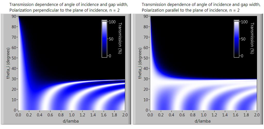
9 For angles of incidence greater than the critical angle of total internal reflection, transmission is only via evanescent waves in the gap, which die out exponentially. As a result, the transmission is only high for small gap widths, as shown below. The higher the index of refraction, the more strongly the incident wave is reflected, and the quicker the evanescent wave dies out. This principle is used to create tunable beam splitters. Any desired transmission coefficient can be realized by adjusting the gap width appropriately. Next, we can plot many trends as a function of angle of incidence and not index of refraction to get a feel for how the transmission depends on incidence angle. The results are shown below for n 2, plotted in 5 increments starting from 0 in red to 90 for the last black curve. As these plots show, the critical angle of total internal reflection divides the periodic curves from the damped curves. Also note that as the angle of incidence increases, the resonant gap widths increase. Finally note that for parallel polarization, the transmission reaches 00% for all gap widths d at a certain angle. This is Brewster's angle, as discussed in class.

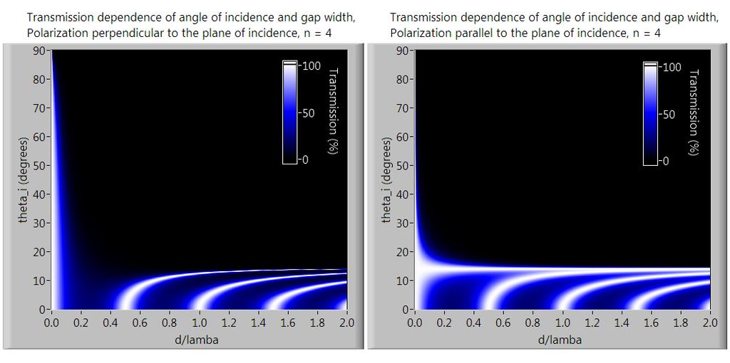
10 Perhaps Brewster's angle is most visible if we make an intensity plot so that the transmission can be a smooth function of both the angle of incidence and the gap width. The results are shown below. Lighter colors represent higher transmission. White represents 00% transmission and black represents 0% transmission. The x axis is the gap width d/λ and the y axis is the angle of incidence θ i. The white streaks occur at the resonant wavelengths of the system. The resonant wavelengths start at half-integer multiples of the gap width for normal incidence, and then bend towards higher values as the angle of incidence increases. After the critical angle of total internal reflection is reached, the plot becomes black except for at very small gaps widths where tunneling is supported. Comparing the results for the perpendicular polarization and the parallel polarization, we see a bright bar of strong transmission right before the critical angle in the parallel polarization. This is Brewster's angle. Total transmission is encouraged at Brewster's angle independent of gap width, but it only occurs in one polarization. The plots below show the cases of n 2 and n 4. From these we see that changing the index of refraction of the materials does not change the overall pattern, but simply lowers Brewster's angle and the critical angle, as well as increasing the contrast between highs and lows.
11
Jackson 7.6 Homework Problem Solution Dr. Christopher S. Baird University of Massachusetts Lowell
 Jackson 7.6 Homework Problem Solution Dr. Christopher S. Baird University of Massachusetts Lowell PROBLEM: A plane wave of frequency ω is incident normally from vacuum on a semi-infinite slab of material
Lecture 1 Notes, Electromagnetic Theory II Dr. Christopher S. Baird, faculty.uml.edu/cbaird University of Massachusetts Lowell
 Lecture 1 Notes, Electromagnetic Theory II Dr. Christopher S. Baird, faculty.uml.edu/cbaird University of Massachusetts Lowell 1. Overview of the Course - Last semester we covered electrostatics, magnetostatics,
- 1 - θ 1. n 1. θ 2. mirror. object. image
 TEST 5 (PHY 50) 1. a) How will the ray indicated in the figure on the following page be reflected by the mirror? (Be accurate!) b) Explain the symbols in the thin lens equation. c) Recall the laws governing
Lecture 5 Notes, Electromagnetic Theory II Dr. Christopher S. Baird, faculty.uml.edu/cbaird University of Massachusetts Lowell
 Lecture 5 Notes, Electromagnetic Theory II Dr. Christopher S. Baird, faculty.uml.edu/cbaird University of Massachusetts Lowell 1. Waveguides Continued - In the previous lecture we made the assumption that
Solutions: Homework 7
 Solutions: Homework 7 Ex. 7.1: Frustrated Total Internal Reflection a) Consider light propagating from a prism, with refraction index n, into air, with refraction index 1. We fix the angle of incidence
Lecture 2 Notes, Electromagnetic Theory II Dr. Christopher S. Baird, faculty.uml.edu/cbaird University of Massachusetts Lowell
 Lecture Notes, Electromagnetic Theory II Dr. Christopher S. Baird, faculty.uml.edu/cbaird University of Massachusetts Lowell 1. Dispersion Introduction - An electromagnetic wave with an arbitrary wave-shape
Lecture 8 Notes, Electromagnetic Theory II Dr. Christopher S. Baird, faculty.uml.edu/cbaird University of Massachusetts Lowell
 Lecture 8 Notes, Electromagnetic Theory II Dr. Christopher S. Baird, faculty.uml.edu/cbaird University of Massachusetts Lowell 1. Scattering Introduction - Consider a localized object that contains charges
Today in Physics 218: Fresnel s equations
 Today in Physics 8: Fresnel s equations Transmission and reflection with E parallel to the incidence plane The Fresnel equations Total internal reflection Polarization on reflection nterference R 08 06
(a) Show that the amplitudes of the reflected and transmitted waves, corrrect to first order
 Show that the amplitudes of the reflected and transmitted waves, corrrect to first order") Problem 1. A conducting slab A plane polarized electromagnetic wave E = E I e ikz ωt is incident normally on a flat uniform sheet of an excellent conductor (σ ω) having thickness D. Assume that in space
Problem 1. A conducting slab A plane polarized electromagnetic wave E = E I e ikz ωt is incident normally on a flat uniform sheet of an excellent conductor (σ ω) having thickness D. Assume that in space
Total Internal Reflection & Metal Mirrors
 Phys 531 Lecture 7 15 September 2005 Total Internal Reflection & Metal Mirrors Last time, derived Fresnel relations Give amplitude of reflected, transmitted waves at boundary Focused on simple boundaries:
Wave Propagation in Uniaxial Media. Reflection and Transmission at Interfaces
 Lecture 5: Crystal Optics Outline 1 Homogeneous, Anisotropic Media 2 Crystals 3 Plane Waves in Anisotropic Media 4 Wave Propagation in Uniaxial Media 5 Reflection and Transmission at Interfaces Christoph
Wave Phenomena Physics 15c. Lecture 15 Reflection and Refraction
 Wave Phenomena Physics 15c Lecture 15 Reflection and Refraction What We (OK, Brian) Did Last Time Discussed EM waves in vacuum and in matter Maxwell s equations Wave equation Plane waves E t = c E B t
1. Consider the biconvex thick lens shown in the figure below, made from transparent material with index n and thickness L.
 Optical Science and Engineering 2013 Advanced Optics Exam Answer all questions. Begin each question on a new blank page. Put your banner ID at the top of each page. Please staple all pages for each individual
Problem set 3. Electromagnetic waves
 Second Year Electromagnetism Michaelmas Term 2017 Caroline Terquem Problem set 3 Electromagnetic waves Problem 1: Poynting vector and resistance heating This problem is not about waves but is useful to
Electrodynamics I Final Exam - Part A - Closed Book KSU 2005/12/12 Electro Dynamic
 Electrodynamics I Final Exam - Part A - Closed Book KSU 2005/12/12 Name Electro Dynamic Instructions: Use SI units. Short answers! No derivations here, just state your responses clearly. 1. (2) Write an
Characterization of Left-Handed Materials
 Characterization of Left-Handed Materials Massachusetts Institute of Technology 6.635 lecture notes 1 Introduction 1. How are they realized? 2. Why the denomination Left-Handed? 3. What are their properties?
ECE 484 Semiconductor Lasers
 ECE 484 Semiconductor Lasers Dr. Lukas Chrostowski Department of Electrical and Computer Engineering University of British Columbia January, 2013 Module Learning Objectives: Understand the importance of
Calculating Thin Film Stack Properties
 Lecture 5: Thin Films Outline 1 Thin Films 2 Calculating Thin Film Stack Properties 3 Fabry-Perot Tunable Filter 4 Anti-Reflection Coatings 5 Interference Filters Christoph U. Keller, Leiden University,
Electromagnetic Waves
 Physics 8 Electromagnetic Waves Overview. The most remarkable conclusion of Maxwell s work on electromagnetism in the 860 s was that waves could exist in the fields themselves, traveling with the speed
Today in Physics 218: stratified linear media I
 Today in Physics 28: stratified linear media I Interference in layers of linear media Transmission and reflection in stratified linear media, viewed as a boundary-value problem Matrix formulation of the
LECTURE 23: LIGHT. Propagation of Light Huygen s Principle
 LECTURE 23: LIGHT Propagation of Light Reflection & Refraction Internal Reflection Propagation of Light Huygen s Principle Each point on a primary wavefront serves as the source of spherical secondary
Propagation of EM Waves in material media
 Propagation of EM Waves in material media S.M.Lea 09 Wave propagation As usual, we start with Maxwell s equations with no free charges: D =0 B =0 E = B t H = D t + j If we now assume that each field has
Electromagnetic fields and waves
 Electromagnetic fields and waves Maxwell s rainbow Outline Maxwell s equations Plane waves Pulses and group velocity Polarization of light Transmission and reflection at an interface Macroscopic Maxwell
Problem 8.0 Make Your Own Exam Problem for Midterm II by April 13
 MASSACHUSETTS INSTITUTE OF TECHNOLOGY Department of Electrical Engineering and Computer Science 6.007 Electromagnetic Energy: From Motors to Lasers Spring 2011 Problem Set 8: Electromagnetic Waves at Boundaries
LECTURE 23: LIGHT. Propagation of Light Huygen s Principle
 LECTURE 23: LIGHT Propagation of Light Reflection & Refraction Internal Reflection Propagation of Light Huygen s Principle Each point on a primary wavefront serves as the source of spherical secondary
Massachusetts Institute of Technology Physics 8.03SC Fall 2016 Homework 9
 Massachusetts Institute of Technology Physics 8.03SC Fall 016 Homework 9 Problems Problem 9.1 (0 pts) The ionosphere can be viewed as a dielectric medium of refractive index ωp n = 1 ω Where ω is the frequency
Chapter 1 - The Nature of Light
 David J. Starling Penn State Hazleton PHYS 214 Electromagnetic radiation comes in many forms, differing only in wavelength, frequency or energy. Electromagnetic radiation comes in many forms, differing
Calculating Thin Film Stack Properties. Polarization Properties of Thin Films
 Lecture 6: Thin Films Outline 1 Thin Films 2 Calculating Thin Film Stack Properties 3 Polarization Properties of Thin Films 4 Anti-Reflection Coatings 5 Interference Filters Christoph U. Keller, Utrecht
Some Topics in Optics
 Some Topics in Optics The HeNe LASER The index of refraction and dispersion Interference The Michelson Interferometer Diffraction Wavemeter Fabry-Pérot Etalon and Interferometer The Helium Neon LASER A
Multilayer Reflectivity
 Multilayer Reflectivity John E. Davis jed@jedsoft.org January 5, 2014 1 Introduction The purpose of this document is to present an ab initio derivation of the reflectivity for a plane electromagnetic wave
C. Incorrect! The velocity of electromagnetic waves in a vacuum is the same, 3.14 x 10 8 m/s.
 AP Physics - Problem Drill 21: Physical Optics 1. Which of these statements is incorrect? Question 01 (A) Visible light is a small part of the electromagnetic spectrum. (B) An electromagnetic wave is a
Waves & Oscillations
 Physics 42200 Waves & Oscillations Lecture 32 Electromagnetic Waves Spring 2016 Semester Matthew Jones Electromagnetism Geometric optics overlooks the wave nature of light. Light inconsistent with longitudinal
Experiment O-2. The Michelson Interferometer
 Experiment O-2 The Michelson Interferometer The Michelson interferometer is one of the best known and historically important interferometers. It is a very accurate length-measuring device and has been
ECE 604, Lecture 17. October 30, In this lecture, we will cover the following topics: Reflection and Transmission Single Interface Case
 ECE 604, Lecture 17 October 30, 2018 In this lecture, we will cover the following topics: Duality Principle Reflection and Transmission Single Interface Case Interesting Physical Phenomena: Total Internal
REFLECTION AND REFRACTION OF PLANE EM WAVES
 REFLECTION AND REFRACTION OF PLANE EM WAVES When an electromagnetic wave hits a boundary between different materials, some of the wave s energy is reflected back while the rest continues on through the
and the radiation from source 2 has the form. The vector r points from the origin to the point P. What will the net electric field be at point P?
 Physics 3 Interference and Interferometry Page 1 of 6 Interference Imagine that we have two or more waves that interact at a single point. At that point, we are concerned with the interaction of those
Jackson 2.3 Homework Problem Solution Dr. Christopher S. Baird University of Massachusetts Lowell
 Jackson.3 Homework Problem Solution Dr. Christopher S. Baird University of Massachusetts Lowell PROBLEM: A straight-line charge with constant linear charge λ is located perpendicular to the x-y plane in
CHAPTER 9 ELECTROMAGNETIC WAVES
 CHAPTER 9 ELECTROMAGNETIC WAVES Outlines 1. Waves in one dimension 2. Electromagnetic Waves in Vacuum 3. Electromagnetic waves in Matter 4. Absorption and Dispersion 5. Guided Waves 2 Skip 9.1.1 and 9.1.2
MASSACHUSETTS INSTITUTE OF TECHNOLOGY Department of Electrical Engineering and Computer Science
 Time: March 10, 006, -3:30pm MASSACHUSETTS INSTITUTE OF TECHNOLOGY Department of Electrical Engineering and Computer Science 6.097 (UG) Fundamentals of Photonics 6.974 (G) Quantum Electronics Spring 006
Chapter 5. Photonic Crystals, Plasmonics, and Metamaterials
 Chapter 5. Photonic Crystals, Plasmonics, and Metamaterials Reading: Saleh and Teich Chapter 7 Novotny and Hecht Chapter 11 and 12 1. Photonic Crystals Periodic photonic structures 1D 2D 3D Period a ~
The Interaction of Light and Matter: α and n
 The Interaction of Light and Matter: α and n The interaction of light and matter is what makes life interesting. Everything we see is the result of this interaction. Why is light absorbed or transmitted
PHYS 110B - HW #5 Fall 2005, Solutions by David Pace Equations referenced equations are from Griffiths Problem statements are paraphrased
 PHYS 0B - HW #5 Fall 005, Solutions by David Pace Equations referenced equations are from Griffiths Problem statements are paraphrased [.] Imagine a prism made of lucite (n.5) whose cross-section is a
Lecture 36 Date:
 Lecture 36 Date: 5.04.04 Reflection of Plane Wave at Oblique Incidence (Snells Law, Brewster s Angle, Parallel Polarization, Perpendicular Polarization etc.) Introduction to RF/Microwave Introduction One
3 December Lesson 5.5
 Preparation Assignments for Homework #8 Due at the start of class. Reading Assignments Please see the handouts for each lesson for the reading assignments. 3 December Lesson 5.5 A uniform plane wave is
Physics 142 Wave Optics 1 Page 1. Wave Optics 1. For every complex problem there is one solution that is simple, neat, and wrong. H.L.
 Physics 142 Wave Optics 1 Page 1 Wave Optics 1 For every complex problem there is one solution that is simple, neat, and wrong. H.L. Mencken Interference and diffraction of waves The essential characteristic
Experiment 6: Interferometers
 Experiment 6: Interferometers Nate Saffold nas2173@columbia.edu Office Hour: Mondays, 5:30PM-6:30PM @ Pupin 1216 INTRO TO EXPERIMENTAL PHYS-LAB 1493/1494/2699 NOTE: No labs and no lecture next week! Outline
Name Final Exam May 1, 2017
 Name Final Exam May 1, 217 This test consists of five parts. Please note that in parts II through V, you can skip one question of those offered. Some possibly useful formulas appear below. Constants, etc.
34. Even more Interference Effects
 34. Even more Interference Effects The Fabry-Perot interferometer Thin-film interference Anti-reflection coatings Single- and multi-layer Advanced topic: Photonic crystals Natural and artificial periodic
POLARISATION. We have not really discussed the direction of the Electric field other that that it is perpendicular to the direction of motion.
 POLARISATION Light is a transverse electromagnetic wave. We have not really discussed the direction of the Electric field other that that it is perpendicular to the direction of motion. If the E field
Electromagnetic Waves Across Interfaces
 Lecture 1: Foundations of Optics Outline 1 Electromagnetic Waves 2 Material Properties 3 Electromagnetic Waves Across Interfaces 4 Fresnel Equations 5 Brewster Angle 6 Total Internal Reflection Christoph
Interferometers. PART 1: Michelson Interferometer The Michelson interferometer is one of the most useful of all optical instru
 Interferometers EP421 Lab Interferometers Introduction: Interferometers are the key to accurate distance measurement using optics. Historically, when mechanical measurements dominated, interferometers
Waves. Daniel S. Weile. ELEG 648 Waves. Department of Electrical and Computer Engineering University of Delaware. Plane Waves Reflection of Waves
 Waves Daniel S. Weile Department of Electrical and Computer Engineering University of Delaware ELEG 648 Waves Outline Outline Introduction Let s start by introducing simple solutions to Maxwell s equations
PHYS 3313 Section 001 Lecture # 22
 PHYS 3313 Section 001 Lecture # 22 Dr. Barry Spurlock Simple Harmonic Oscillator Barriers and Tunneling Alpha Particle Decay Schrodinger Equation on Hydrogen Atom Solutions for Schrodinger Equation for
Polarization. If the original light is initially unpolarized, the transmitted intensity I is half the original intensity I 0 :
 33-4 33-4 Polarization Polarization Electromagnetic waves are polarized if their electric field vectors are all in a single plane, called the plane of oscillation. Light waves from common sources are not
Numerical modeling of thin film optical filters
 Numerical modeling of thin film optical filters Daniela Topasna and Gregory A Topasna Department of Physics and Astronomy Virginia ilitary Institute Lexington VA ASTRACT Thin films are an important and
Problem Set 5: Solutions
 University of Alabama Department of Physics and Astronomy Department of Electrical and Computer Engineering PH 495/ECE 493 LeClair & Kung Spring 011 Problem Set 5: Solutions 1. Bekefi & Barrett 8.; Hecht
Frozen light in photonic crystals with degenerate band edge
 Frozen light in photonic crystals with degenerate band edge Alex Figotin and Ilya Vitebskiy Department of Mathematics, University of California, Irvine, California 92697, USA Received 9 October 2006; published
Massachusetts Institute of Technology Physics 8.03 Practice Final Exam 3
 Massachusetts Institute of Technology Physics 8.03 Practice Final Exam 3 Instructions Please write your solutions in the white booklets. We will not grade anything written on the exam copy. This exam is
Stellar Astrophysics: The Continuous Spectrum of Light
 Stellar Astrophysics: The Continuous Spectrum of Light Distance Measurement of Stars Distance Sun - Earth 1.496 x 10 11 m 1 AU 1.581 x 10⁻⁵ ly Light year 9.461 x 10 15 m 6.324 x 10 4 AU 1 ly Parsec (1
OPSE FINAL EXAM Fall 2016 YOU MUST SHOW YOUR WORK. ANSWERS THAT ARE NOT JUSTIFIED WILL BE GIVEN ZERO CREDIT.
 CLOSED BOOK. Equation Sheet is provided. YOU MUST SHOW YOUR WORK. ANSWERS THAT ARE NOT JUSTIFIED WILL BE GIVEN ZERO CREDIT. ALL NUMERICAL ANSERS MUST HAVE UNITS INDICATED. (Except dimensionless units like
Grading. Class attendance: (1 point/class) x 9 classes = 9 points maximum Homework: (10 points/hw) x 3 HW = 30 points maximum
 x 9 classes = 9 points maximum Homework: (10 points/hw) x 3 HW = 30 points maximum") Grading Class attendance: (1 point/class) x 9 classes = 9 points maximum Homework: (10 points/hw) x 3 HW = 30 points maximum Maximum total = 39 points Pass if total >= 20 points Fail if total
Grading Class attendance: (1 point/class) x 9 classes = 9 points maximum Homework: (10 points/hw) x 3 HW = 30 points maximum Maximum total = 39 points Pass if total >= 20 points Fail if total
Report submitted to Prof. P. Shipman for Math 540, Fall 2009
 Dynamics at the Horsetooth Volume 1, 009. Three-Wave Interactions of Spin Waves Aaron Hagerstrom Department of Physics Colorado State University aaronhag@rams.colostate.edu Report submitted to Prof. P.
Constructive vs. destructive interference; Coherent vs. incoherent interference
 Constructive vs. destructive interference; Coherent vs. incoherent interference Waves that combine in phase add up to relatively high irradiance. = Constructive interference (coherent) Waves that combine
Plasma Physics Prof. V. K. Tripathi Department of Physics Indian Institute of Technology, Delhi
 Plasma Physics Prof. V. K. Tripathi Department of Physics Indian Institute of Technology, Delhi Lecture No. # 09 Electromagnetic Wave Propagation Inhomogeneous Plasma (Refer Slide Time: 00:33) Today, I
Experiment 8. Fresnel Coefficients. 8.1 Introduction. References
 Experiment 8 Fresnel Coefficients References Optics by Eugene Hecht, Chapter 4 Introduction to Modern Optics by Grant Fowles, Chapter 2 Principles of Optics by Max Born and Emil Wolf, Chapter 1 Optical
REFLECTION AND REFRACTION AT A SINGLE INTERFACE
 REFLECTION AND REFRACTION AT A SINGLE INTERFACE 5.1 THE BEHAVIOUR OF LIGHT AT A DIELECTRIC INTERFACE The previous Chapters have been concerned with the propagation of waves in empty space or in uniform,
PS210 - Optical Techniques. Section VI
 PS210 - Optical Techniques Section VI Section I Light as Waves, Rays and Photons Section II Geometrical Optics & Optical Instrumentation Section III Periodic and Non-Periodic (Aperiodic) Waves Section
II Theory Of Surface Plasmon Resonance (SPR)
") II Theory Of Surface Plasmon Resonance (SPR) II.1 Maxwell equations and dielectric constant of metals Surface Plasmons Polaritons (SPP) exist at the interface of a dielectric and a metal whose electrons
II Theory Of Surface Plasmon Resonance (SPR) II.1 Maxwell equations and dielectric constant of metals Surface Plasmons Polaritons (SPP) exist at the interface of a dielectric and a metal whose electrons
Chapter 2 Basic Optics
 Chapter Basic Optics.1 Introduction In this chapter we will discuss the basic concepts associated with polarization, diffraction, and interference of a light wave. The concepts developed in this chapter
Reflection/Refraction
 Reflection/Refraction Page Reflection/Refraction Boundary Conditions Interfaces between different media imposed special boundary conditions on Maxwell s equations. It is important to understand what restrictions
Lecture 5: Polarization. Polarized Light in the Universe. Descriptions of Polarized Light. Polarizers. Retarders. Outline
 Lecture 5: Polarization Outline 1 Polarized Light in the Universe 2 Descriptions of Polarized Light 3 Polarizers 4 Retarders Christoph U. Keller, Leiden University, keller@strw.leidenuniv.nl ATI 2016,
Surface Plasmon Wave
 Surface Plasmon Wave In this experiment you will learn about a surface plasmon wave. Certain metals (Au, Ag, Co, etc) exhibit a negative dielectric constant at certain regions of the electromagnetic spectrum.
FIBER OPTICS. Prof. R.K. Shevgaonkar. Department of Electrical Engineering. Indian Institute of Technology, Bombay. Lecture: 17.
 FIBER OPTICS Prof. R.K. Shevgaonkar Department of Electrical Engineering Indian Institute of Technology, Bombay Lecture: 17 Optical Sources- Introduction to LASER Fiber Optics, Prof. R.K. Shevgaonkar,
Topic 4: Waves 4.3 Wave characteristics
 Guidance: Students will be expected to calculate the resultant of two waves or pulses both graphically and algebraically Methods of polarization will be restricted to the use of polarizing filters and
Lab 1: Damped, Driven Harmonic Oscillator
 1 Introduction Lab 1: Damped, Driven Harmonic Oscillator The purpose of this experiment is to study the resonant properties of a driven, damped harmonic oscillator. This type of motion is characteristic
ECE Spring Prof. David R. Jackson ECE Dept. Notes 6
 ECE 6341 Spring 2016 Prof. David R. Jackson ECE Dept. Notes 6 1 Leaky Modes v TM 1 Mode SW 1 v= utan u ε R 2 R kh 0 n1 r = ( ) 1 u Splitting point ISW f = f s f > f s We will examine the solutions as the
Fabry-Perot Interferometers
 Fabry-Perot Interferometers Astronomy 6525 Literature: C.R. Kitchin, Astrophysical Techniques Born & Wolf, Principles of Optics Theory: 1 Fabry-Perots are best thought of as resonant cavities formed between
Lab 1: damped, driven harmonic oscillator
 Lab 1: damped, driven harmonic oscillator 1 Introduction The purpose of this experiment is to study the resonant properties of a driven, damped harmonic oscillator. This type of motion is characteristic
Chapter 9. Electromagnetic Waves
 Chapter 9. Electromagnetic Waves 9.1 Waves in One Dimension 9.1.1 The Wave Equation What is a "wave?" Let's start with the simple case: fixed shape, constant speed: How would you represent such a string
Summary of Beam Optics
 Summary of Beam Optics Gaussian beams, waves with limited spatial extension perpendicular to propagation direction, Gaussian beam is solution of paraxial Helmholtz equation, Gaussian beam has parabolic
General Appendix A Transmission Line Resonance due to Reflections (1-D Cavity Resonances)
") A 1 General Appendix A Transmission Line Resonance due to Reflections (1-D Cavity Resonances) 1. Waves Propagating on a Transmission Line General A transmission line is a 1-dimensional medium which can
A 1 General Appendix A Transmission Line Resonance due to Reflections (1-D Cavity Resonances) 1. Waves Propagating on a Transmission Line General A transmission line is a 1-dimensional medium which can
Brewster Angle and Total Internal Reflection
 Lecture 4: Polarization Outline 1 Polarized Light in the Universe 2 Brewster Angle and Total Internal Reflection 3 Descriptions of Polarized Light 4 Polarizers 5 Retarders Christoph U. Keller, Utrecht
Lecture 2: Thin Films. Thin Films. Calculating Thin Film Stack Properties. Jones Matrices for Thin Film Stacks. Mueller Matrices for Thin Film Stacks
 Lecture 2: Thin Films Outline Thin Films 2 Calculating Thin Film Stack Properties 3 Jones Matrices for Thin Film Stacks 4 Mueller Matrices for Thin Film Stacks 5 Mueller Matrix for Dielectrica 6 Mueller
Brewster Angle and Total Internal Reflection
 Lecture 5: Polarization Outline 1 Polarized Light in the Universe 2 Brewster Angle and Total Internal Reflection 3 Descriptions of Polarized Light 4 Polarizers 5 Retarders Christoph U. Keller, Leiden University,
Massachusetts Institute of Technology Physics 8.03 Fall 2004 Final Exam Thursday, December 16, 2004
 You have 3 hours Do all eight problems You may use calculators Massachusetts Institute of Technology Physics 8.03 Fall 004 Final Exam Thursday, December 16, 004 This is a closed-book exam; no notes are
Module 5 : Plane Waves at Media Interface. Lecture 36 : Reflection & Refraction from Dielectric Interface (Contd.) Objectives
 Objectives") Objectives In this course you will learn the following Reflection and Refraction with Parallel Polarization. Reflection and Refraction for Normal Incidence. Lossy Media Interface. Reflection and Refraction
Objectives In this course you will learn the following Reflection and Refraction with Parallel Polarization. Reflection and Refraction for Normal Incidence. Lossy Media Interface. Reflection and Refraction
PRINCIPLES OF PHYSICAL OPTICS
 PRINCIPLES OF PHYSICAL OPTICS C. A. Bennett University of North Carolina At Asheville WILEY- INTERSCIENCE A JOHN WILEY & SONS, INC., PUBLICATION CONTENTS Preface 1 The Physics of Waves 1 1.1 Introduction
Today in Physics 218: impedance of the vacuum, and Snell s Law
 Today in Physics 218: impedance of the vacuum, and Snell s Law The impedance of linear media Spacecloth Reflection and transmission of electromagnetic plane waves at interfaces: Snell s Law and the first
Chapter 33. Electromagnetic Waves
 Chapter 33 Electromagnetic Waves Today s information age is based almost entirely on the physics of electromagnetic waves. The connection between electric and magnetic fields to produce light is own of
Week 7: Interference
 Week 7: Interference Superposition: Till now we have mostly discusssed single waves. While discussing group velocity we did talk briefly about superposing more than one wave. We will now focus on superposition
Interference. Part-2. Gambar: Museum Victoria Australia
 Interference Part-2 Gambar: Museum Victoria Australia Amplitude Splitting Interferometer S 2. Michelson Interferometer The principle: amplitude splitting d HM D F B M1 Detector C M1 E Interference at F
= nm. = nm. = nm
 Chemistry 60 Analytical Spectroscopy PROBLEM SET 5: Due 03/0/08 1. At a recent birthday party, a young friend (elementary school) noticed that multicolored rings form across the surface of soap bubbles.
What Makes a Laser Light Amplification by Stimulated Emission of Radiation Main Requirements of the Laser Laser Gain Medium (provides the light
 What Makes a Laser Light Amplification by Stimulated Emission of Radiation Main Requirements of the Laser Laser Gain Medium (provides the light amplification) Optical Resonator Cavity (greatly increase
APPLICATION OF BILAYER ANISOTROPIC STRUC- TURES FOR DESIGNING LOW-PASS FILTERS AND PO- LARIZERS
 Progress In Electromagnetics Research M, Vol. 29, 95 108, 2013 APPLICATION OF BILAYER ANISOTROPIC STRUC- TURES FOR DESIGNING LOW-PASS FILTERS AND PO- LARIZERS Amir Raeesi *, Ali Abdolali, and Hossein Mirzaei
Chapter 4 Reflection and Transmission of Waves
 4-1 Chapter 4 Reflection and Transmission of Waves ECE 3317 Dr. Stuart Long www.bridgat.com www.ranamok.com Boundary Conditions 4- -The convention is that is the outward pointing normal at the boundary
Problem 8.18 For some types of glass, the index of refraction varies with wavelength. A prism made of a material with
 Problem 8.18 For some types of glass, the index of refraction varies with wavelength. A prism made of a material with n = 1.71 4 30 λ 0 (λ 0 in µm), where λ 0 is the wavelength in vacuum, was used to disperse
Geometrical Optics. = n r. sinθ i
 Name Section Number Lab Partner s Name Geometrical Optics Introduction In geometrical optics, refraction is described by Snell s Law. Refraction refers to the bending of light as it passes from one medium
Laser Types Two main types depending on time operation Continuous Wave (CW) Pulsed operation Pulsed is easier, CW more useful
 Pulsed operation Pulsed is easier, CW more useful") What Makes a Laser Light Amplification by Stimulated Emission of Radiation Main Requirements of the Laser Laser Gain Medium (provides the light amplification) Optical Resonator Cavity (greatly increase
What Makes a Laser Light Amplification by Stimulated Emission of Radiation Main Requirements of the Laser Laser Gain Medium (provides the light amplification) Optical Resonator Cavity (greatly increase
Wave Phenomena Physics 15c
 Wave Phenomena Physics 15c Lecture 15 lectromagnetic Waves (H&L Sections 9.5 7) What We Did Last Time! Studied spherical waves! Wave equation of isotropic waves! Solution e! Intensity decreases with! Doppler
Reversed Cherenkov Radiation in Left Handed Meta material Lecture, Nov 21, 2012 Prof. Min Chen
 Reversed Cherenkov Radiation in Left Handed Meta material 8.07 Lecture, Nov 21, 2012 Prof. Min Chen 1 8.07 is not just an abstract theory; it is a tool which can be applied to change the world around you.