39th International Physics Olympiad - Hanoi - Vietnam Experimental Problem
|
|
|
- Sara Hubbard
- 6 years ago
- Views:
Transcription
1 DIFFERENTIAL THERMOMETRIC METHOD In this problem, we use the differential thermometric method to fulfill the two following tasks: 1. Finding the temperature of solidification of a crystalline solid substance. 2. Determining the efficiency of a solar cell. A. Differential thermometric method In this experiment forward biased silicon diodes are used as temperature sensors to measure temperature. If the electric current through the diode is constant, then the voltage drop across the diode depends on the temperature according to the relation ( ) ( ) α ( ) V T = V T T T 0 (1) 0 where V( T) and V( T ) 0 are respectively the voltage drops across the diode at temperature T and at room temperature T0 (measured in o C), and the factor o (.. ) α = 200± 003 mv/ C (2) The value of V( T0 ) may vary slightly from diode to diode. If two such diodes are placed at different temperatures, the difference between the temperatures can be measured from the difference of the voltage drops across the two diodes. The difference of the voltage drops, called the differential voltage, can be measured with high precision; hence the temperature difference can also be measured with high precision. This method is called the differential thermometric method. The electric circuit used with the diodes in this experiment is shown in Figure 1. Diodes D 1 and D 2 are forward biased by a 9V battery, through 10 kω resistors, R 1 and E R 1 R 2 Δ V V 1 D 1 D 2 V 2 R 2. This circuit keeps the current in the two diodes approximately constant. Figure 1. Electric circuit of the diode If the temperature of diode D 1 is T 1 and that of D 2 is T 2, then according to (1), we have: 1
2 ( ) = ( ) α ( ) V T V T T T and ( ) = ( ) α ( ) V T V T T T The differential voltage is: ( ) ( ) ( ) ( ) α( ) ( ) α( ) Δ V = V T V T = V T V T T T =ΔV T T T ( ) Δ V =ΔV T αδt 0 (3) in which Δ T = T T. By measuring the differential voltage Δ V 2 1, we can determine the temperature difference. To bias the diodes, we use a circuit box, the diagram of which is shown in Figure 2. To D 1 - Blue To D 2 - Red Common- Black 10 kω 10 kω Blue ΔV Red Red V 2 Black 9 V Figure 2. Diagram of the circuit box (top view) The circuit box contains two biasing resistors of 10 kω for the diodes, electrical leads to the 9 V battery, sockets for connecting to the diodes D 1 and D 2, and sockets for connecting to digital multimeters to measure the voltage drop V2 on diode D2 and the differential voltage ΔV of the diodes D1 and D 2. 2
3 B. Task 1: Finding the temperature of solidification of a crystalline substance 1. Aim of the experiment If a crystalline solid substance is heated to the melting state and then cooled down, it solidifies at a fixed temperature, called temperature of solidification, also called the melting point of the substance. The traditional method to determine is to follow the change in temperature with time during the cooling process. Due to the fact that the solidification process is accompanied by the release of the latent heat of the phase transition, the temperature of the substance does not change while the substance is solidifying. If the amount of the substance is large enough, the time interval in which the temperature remains constant is rather long, and one can easily determine this temperature. On the contrary, if the amount of substance is small, this time interval is too short to be observed and hence it is difficult to determine. In order to determine in case of small amount of substance, we use the differential thermometric method, whose principle can be summarized as follows. We use two identical small dishes, one containing a small amount of the substance to be studied, called the le dish, and the other not containing the substance, called the reference dish. The two dishes are put on a heat source, whose temperature varies slowly with time. The thermal flows to and from the two dishes are nearly the same. Each dish contains a temperature sensor (a forward biased silicon diode). While there is no phase change in the substance, the temperature T of the le dish and the temperature T of the ref reference dish vary at nearly the same rate, and thus Δ T = T T varies slowly with ref amp. If there is a phase change in the substance, and during the phase change T does not vary and equals T, while teadily varies, then ΔT varies quickly. The plot of ΔT versus hows an abrupt change. The value of T corresponding to the abrupt change of ΔT is indeed T. s s ref The aim of this experiment is to determine the temperature of solidification of a 3
4 pure crystalline substance, having in the range from 50 o C to 70 o C, by using the traditional and differential thermal analysis methods. The amount of substance used in the experiment is about 20 mg. 2. Apparatus and materials 1. The heat source is a 20 W halogen lamp. 2. The dish holder is a bakelite plate with a square hole in it. A steel plate is fixed on the hole. Two small magnets are put on the steel plate. 3. Two small steel dishes, each contains a silicon diode soldered on it. One dish is used as the reference dish, the other - as the le dish. Cover Ref. dish D 1 D 2 Sample dish Steel plate Magnet s Red 12V/20W bulb Black Blue Figure 3. Apparatus for measuring the solidification temperature Each dish is placed on a magnet. The magnetic force maintains the contact between the dish, the magnet and the steel plate. The magnets also keep a moderate thermal contact between the steel plate and the dishes. A grey plastic box used as a cover to protect the dishes from the outside influence. Figure 3 shows the arrangement of the dishes and the magnets on the dish holder D 1 D 2 and the light bulb. 4. Two digital multimeters are used as voltmeters. They can also measure room temperature by turning the Function selector Red to the o C/ o F function. The voltage function Black of the multimeter has an error of ±2 on the last digit. Blue Note: to prevent the multimeter (see Figure 9) from going into the Auto power Figure 4. The dishes on the dish holder (top view) 4
5 off function, turn the Function selector from OFF position to the desired function while pressing and holding the SELECT button. 5. A circuit box as shown in Figure A 9 V battery. 7. Electrical leads. 8. A small ampoule containing about 20 mg of the substance to be measured. 9. A stop watch 10. A calculator 11. Graph papers. 3. Experiment 1. The magnets are placed on two equivalent locations on the steel plate. The reference dish and the empty le dish are put on the magnets as shown in the Figure 4. We use the dish on the left side as the reference dish, with diode D 1 on it (D 1 is called the reference diode), and the dish on the right side as the le dish, with diode D 2 on it (D 2 is called the measuring diode). Put the lamp-shade up side down as shown in Figure 5. Do not switch the lamp on. Put the dish holder on the lamp. Connect the apparatuses so that you can measure the voltage drop on the diode D 2, that is V = V2, and the differential voltage ΔV. In order to eliminate errors due to the warming up period of the instruments and devices, it is strongly recommended that the complete measurement circuit be switched on for about 5 minutes before starting real experiments. Figure 5. Using the halogen lamp as a heat source T ( ) 1.1. Measure the room temperature and the voltage drop 0 V T across 0 diode D 2 fixed to the le dish, at room temperature T Calculate the voltage drops V ( 50 o C ), V ( 70 o C ) and V ( 80 o C ) on the measuring diode at temperatures 50 o C, 70 o C and 80 o C, respectively. 5
6 2. With both dishes still empty, switch the lamp on. Follow V sam. When the temperature of the le dish reaches amp ~ 80 o C, switch the lamp off Wait until amp ~ 70 o C, and then follow the change in V and ΔV with time, while the steel plate is cooling down. Note down the values of V and Δ V every 10 s to 20 s in the table provided in the answer sheet. If Δ V varies quickly, the time interval between consecutive measurements may be shorter. When the temperature of the le dish decreases to amp ~ 50 o C, the measurement is stopped Plot the graph of V versus t, called Graph 1, on a graph paper provided Plot the graph of ΔV versus V, called Graph 2, on a graph paper provided. Note: for 2.2 and 2.3 do not forget to write down the correct name of each graph. 3. Pour the substance from the ampoule into the le dish. Repeat the experiment identically as mentioned in section Write down the data of V and answer sheet. ΔV with time t in the table provided in the 3.2. Plot the graph of V versus t, called Graph 3, on a graph paper provided Plot the graph of ΔV versus V, called Graph 4, on a graph paper provided. Note: for 3.2 and 3.3 do not forget to write down the correct name of each graph. 4. By comparing the graphs in section 2 and section 3, determine the temperature of solidification of the substance Using the traditional method to determine : by comparing the graphs of V versus t in sections 3 and 2, i.e. Graph 3 and Graph 1, mark the point on Graph 3 where the substance solidifies and determine the value V s (corresponding to this point) V of. 6
7 Find out the temperature of solidification of the substance and estimate its error Using the differential thermometric method to determine : by comparing the graphs of ΔV versus V in sections 3 and 2, i.e. Graph 4 and Graph 2, mark the point on Graph 4 where the substance solidifies and determine the value V of V. s Find out the temperature of solidification of the substance From errors of measurement data and instruments, calculate the error of obtained with the differential thermometric method. Write down the error calculations and finally write down the values of together with its error in the answer sheet. C. Task 2: Determining the efficiency of a solar cell under illumination of an incandescent lamp 1. Aim of the experiment The aim of the experiment is to determine the efficiency of a solar cell under illumination of an incandescent lamp. Efficiency is defined as the ratio of the electrical power that the solar cell can supply to an external circuit, to the total radiant power received by the cell. The efficiency depends on the incident radiation spectrum. In this experiment the radiation incident to the cell is that of an incandescent halogen lamp. In order to determine the efficiency of the solar cell, we have to measure the irradiance E at a point situated under the lamp, at a distance d from the lamp along the vertical direction, and the d = 12 cm maximum power Pmax of the solar cell when it is placed at this point. In this experiment, d = 12 cm (Figure 6). Irradiance E can be defined by: E =Φ / S Figure 6. in which Φ is the radiant flux (radiant Using the halogen lamp power), and S is the area of the as a light source illuminated surface. 7
8 2. Apparatus and materials 1. The light source is a 20W halogen lamp. 2. The radiation detector is a hollow cone made of copper, the inner surface of it is blackened with soot (Figure 7). The cone is incompletely thermally isolated from the surrounding. In this experiment, the detector is considered an ideal black body. To measure temperature, we use silicon diodes. The measuring diode is fixed to the radiation detector (D 2 in Figure 1 and Figure 7), so that its temperature equals that of the cone. The reference diode is placed on the inner side of the wall of the box containing the detector; its temperature equals that of the surrounding. The total heat capacity of the detector (the cone and the measuring diode) is C = (. ±. ) J/K. The detector is covered by a very thin polyethylene film; the radiation absorption and reflection of which can be neglected. Common Thermal insulator Reference diode D 1 Measuring diode D 2 Blue Black Red Figure 7. Diagram of the radiation detector 3. A circuit box as shown in Figure A piece of solar cell fixed on a plastic box (Figure 8). The area of the cell includes some metal connection strips. For the efficiency calculation these strips are considered parts of the cell. 5. Two digital multimeters. When used to measure the voltage, they have a very large internal resistance, which can be considered infinitely large. When we use them to measure the current, we cannot neglect their internal resistance. The voltage function of the multimeter has an error of ±2 on the last digit. Red Black Figure 8. The solar cell 8
9 The multimeters can also measure the room temperature. Note: to prevent the multimeter (see Figure 9) from going into the Auto power off function, turn the Function selector from OFF position to the desired function while pressing and holding the SELECT button. 6. A 9 V battery 7. A variable resistor. 8. A stop watch 9. A ruler with 1mm divisions 10. Electrical leads. 11. Graph papers. 3. Experiment When the detector receives energy from radiation, it heats up. At the same time, the detector loses its heat by several mechanisms, such as thermal conduction, convection, radiation etc...thus, the radiant energy received by detector in a time interval dt is equal to the sum of the energy needed to increase the detector temperature and the energy transferred from the detector to the surrounding: Φ dt = CdT + dq where C is the heat capacity of the detector and the diode, dt - the temperature increase and dq - the heat loss. When the temperature difference between the detector and the surrounding Δ T = T T 0 is small, we can consider that the heat dq transferred from the detector to the surrounding in the time interval dt is approximately proportional to ΔT and dt, that is dq = kδtdt, with k being a factor having the dimension of W/K. Hence, assuming that k is constant and Δ T is small, we have: Φ dt = CdT + kδ Tdt = Cd( Δ T ) + kδtdt or d( ΔT) k Φ + Δ T = dt C C (4) The solution of this differential equation determines the variation of the temperature difference ΔT with time t, from the moment the detector begins to receive the light with a constant irradiation, assuming that at t=0, Δ T =0 k Φ t Δ T () t = 1 e C k (5) When the radiation is switched off, the mentioned above differential equation becomes 9
10 d( ΔT) k + Δ T = 0 (6) dt C and the temperature difference ΔT varies with the time according to the following formula: where starts). () ( 0 ) k t C Δ T t = Δ T e (7) ΔT( 0) is the temperature difference at t = 0 (the moment when the measurement 1. Determine the room temperature T Compose an electric circuit comprising the diode sensors, the circuit box and the multimeters to measure the temperature of the detector. In order to eliminate errors due to the warming up period of the instruments and devices, it is strongly recommended that the complete measurement circuit be switched on for about 5 minutes before starting real experiments Place the detector under the light source, at a distance of d = 12 cm to the lamp. The lamp is off. Follow the variation of ΔV for about 2 minutes with ling intervals of 10 s and determine the value of Δ VT ( 0) in equation (3) Switch the lamp on to illuminate the detector. Follow the variation of ΔV. Every s, write down a value of Δ V in the table provided in the answer sheet. (Note: columns x and y of the table will be used later in section 4.). After 2 minutes, switch the lamp off Move the detector away from the lamp. Follow the variation of ΔV for about 2 minutes after that. Every s, write down a value of Δ V in the table provided in the answer sheet. (Note: columns x and y of the table will be used later in section 3.). Hints: As the detector has a thermal inertia, it is recommended not to use some data obtained immediately after the moment the detector begins to be illuminated or ceases to be illuminated. 3. Plot a graph in an x-y system of coordinates, with variables x and y chosen appropriately, in order to prove that after the lamp is switched off, equation (7) is satisfied Write down the expression for variables x and y Plot a graph of y versus x, called Graph From the graph, determine the value of k. 4. Plot a graph in an x-y system of coordinates, with variables x and y chosen 10
11 appropriately, in order to prove that when the detector is illuminated, equation (5) is satisfied Write down the expressions for variables x and y Plot a graph of y versus x, called Graph Determine the irradiance E at the orifice of the detector. 5. Put the solar cell to the same place where the radiation detector was. Connect the solar cell to an appropriate electric circuit comprising the multimeters and a variable resistor which is used to change the load of the cell. Measure the current in the circuit and the voltage on the cell at different values of the resistor Draw a diagram of the circuit used in this experiment By rotating the knob of the variable resistor, you change the value of the load. Note the values of current I and voltage V at each position of the knob Plot a graph of the power of the cell, which supplies to the load, as a function of the current through the cell. This is Graph From the graph deduce the maximum power P max of the cell and estimate its error Write down the expression for the efficiency of the cell that corresponds to the obtained maximum power. Calculate its value and error. 11

 from going into the")

12 Contents of the experiment kit (see also Figure 10) 1 Halogen lamp 220 V/ 20 W 9 Stop watch 2 Dish holder 10 Calculator 3 Dish 11 Radiation detector 4 Multimeter 12 Solar cell 5 Circuit box 13 Variable resistor 6 9 V battery 14 Ruler 7 Electrical leads 15 Box used as a cover 8 Ampoule with substance to be measured Note: to prevent the multimeter (see Figure 9) from going into the Auto power off function, turn the Function selector from OFF position to the desired function while pressing and holding the SELECT button. Select Function selector Figure 9. Digital multimeter 12


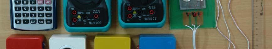
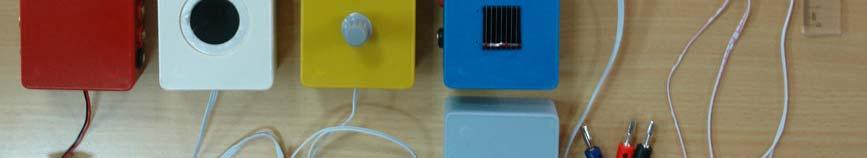
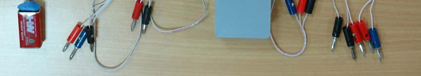
13 Figure 10. Contents of the experiment kit 13
39th International Physics Olympiad - Hanoi - Vietnam Experimental Problem
 Experimental Problem DIFFERENTIAL THERMOMETRIC METHOD In this problem, we use the differential thermometric method to fulfill the two following tasks: 1. Finding the temperature of solidification of a
PLANCK S CONSTANT IN THE LIGHT OF AN INCANDESCENT LAMP
 PLANCK S CONSTANT IN THE LIGHT OF AN INCANDESCENT LAMP In 1900 Planck introduced the hypothesis that light is emitted by matter in the form of quanta of energy hν. In 1905 Einstein extended this idea proposing
Solar cells E Introduction. Equipment used for this experiment is displayed in Fig. 2.1.
 2.0 Introduction Equipment used for this experiment is displayed in Fig. 2.1. Figure 2.1 Equipment used for experiment E2. List of equipment (see Fig. 2.1): A: Solar cell B: Solar cell C: Box with slots
Physics Department. CfE Higher Unit 3: Electricity. Problem Booklet
 Physics Department CfE Higher Unit 3: Electricity Problem Booklet Name Class 1 Contents Exercise 1: Monitoring and measuring a.c. Exercise 2: Current, voltage, power and resistance Exercise 3: Electrical
NATIONAL QUALIFICATIONS CURRICULUM SUPPORT. Physics. Electricity. Questions and Solutions. James Page Arthur Baillie [HIGHER]
![NATIONAL QUALIFICATIONS CURRICULUM SUPPORT. Physics. Electricity. Questions and Solutions. James Page Arthur Baillie [HIGHER]](/thumbs/86/93982339.jpg "NATIONAL QUALIFICATIONS CURRICULUM SUPPORT. Physics. Electricity. Questions and Solutions. James Page Arthur Baillie [HIGHER]") NTIONL QULIFICTIONS CURRICULUM SUPPORT Physics Electricity Questions and Solutions James Page rthur Baillie [HIGHER] The Scottish Qualifications uthority regularly reviews the arrangements for National
NTIONL QULIFICTIONS CURRICULUM SUPPORT Physics Electricity Questions and Solutions James Page rthur Baillie [HIGHER] The Scottish Qualifications uthority regularly reviews the arrangements for National
Farr High School HIGHER PHYSICS. Unit 3 Electricity. Question Booklet
 Farr High School HIGHER PHYSICS Unit 3 Electricity Question Booklet 1 MONITORING ND MESURING.C. 1. What is the peak voltage of the 230 V mains supply? The frequency of the mains supply is 50 Hz. How many
EXPERIMENT 5A RC Circuits
 EXPERIMENT 5A Circuits Objectives 1) Observe and qualitatively describe the charging and discharging (decay) of the voltage on a capacitor. 2) Graphically determine the time constant for the decay, τ =.
CHARGE AND ELECTRIC CURRENT:
 ELECTRICITY: CHARGE AND ELECTRIC CURRENT ELECTRIC CHARGE ELECTRIC CURRENT ELECTRIC CIRCUIT DEFINITION AND COMPONENTS EFFECTS OF ELECTRIC CURRENT TYPES OF CIRCUITS ELECTRIC QUANTITIES VOLTAGE CURRENT RESISTANCE
Past Exam Questions Core Practicals Physics Paper 1
 Past Exam Questions Core Practicals Physics Paper Name: Class: Date: Time: 48 minutes Marks: 48 marks Comments: Page of 53 A student used the apparatus below to find out how the resistance of a light-dependent
EXPERIMENT NO. 4. Thermal Radiation: the Stefan-Boltzmann Law
 1 EXPERIMENT NO. 4 Thermal Radiation: the Stefan-Boltzmann Law References: Physics for Scientists and Engineers, Serway and Jewett. Sections 40.1 An Introduction to Thermal Physics, Schroeder, Section
Lab 2. Characterization of Solar Cells
 Lab 2. Characterization of Solar Cells Physics Enhancement Programme Department of Physics, Hong Kong Baptist University 1. OBJECTIVES To familiarize with the principles of commercial solar cells To characterize
Electricity. Prepared by Juan Blázquez, Alissa Gildemann. Electric charge is a property of all objects. It is responsible for electrical phenomena.
 Unit 11 Electricity 1. Electric charge Electric charge is a property of all objects. It is responsible for electrical phenomena. Electrical phenomena are caused by the forces of attraction and repulsion.
LESSON 5: ELECTRICITY II
 LESSON 5: ELECTRICITY II The first two points are a review of the previous lesson 1.1.ELECTRIC CHARGE - Electric charge is a property of all objects and is responsible for electrical phenomena. -All matter
EXPERIMENT ET: ENERGY TRANSFORMATION & SPECIFIC HEAT
 MASSACHUSETTS INSTITUTE OF TECHNOLOGY Physics Department Physics 8.01X Fall 2000 EXPERIMENT ET: ENERGY TRANSFORMATION & SPECIFIC HEAT We have introduced different types of energy which help us describe
Electrical Circuits. Winchester College Physics. makptb. c D. Common Time man. 3rd year Revision Test
 Name... Set... Don.... manner~ man makptb Winchester College Physics 3rd year Revision Test Electrical Circuits Common Time 2011 Mark multiple choice answers with a cross (X) using the box below. I A B
EDEXCEL NATIONALS UNIT 5 - ELECTRICAL AND ELECTRONIC PRINCIPLES. ASSIGNMENT No.2 - CAPACITOR NETWORK
 EDEXCEL NATIONALS UNIT 5 - ELECTRICAL AND ELECTRONIC PRINCIPLES ASSIGNMENT No.2 - CAPACITOR NETWORK NAME: I agree to the assessment as contained in this assignment. I confirm that the work submitted is
EE 241 Experiment #5: TERMINAL CHARACTERISTICS OF LINEAR & NONLINEAR RESISTORS 1
 EE 241 Experiment #5: TERMINA CHARACTERISTICS OF INEAR & NONINEAR RESISTORS 1 PURPOSE: To experimentally determine some of the important characteristics of common linear and non-linear resistors. To study
Cambridge International Examinations Cambridge Ordinary Level
 Cambridge International Examinations Cambridge Ordinary Level *6032081406* PHYSICS 5054/22 Paper 2 Theory May/June 2018 1 hour 45 minutes Candidates answer on the Question Paper. No Additional Materials
REVISED HIGHER PHYSICS REVISION BOOKLET ELECTRONS AND ENERGY
 REVSED HGHER PHYSCS REVSON BOOKLET ELECTRONS AND ENERGY Kinross High School Monitoring and measuring a.c. Alternating current: Mains supply a.c.; batteries/cells supply d.c. Electrons moving back and forth,
Practice exam-style paper
 Practice exam-style paper Paper 6 Alternative to Practical Write your answers on the question paper. The number of marks is given in brackets [ ] at the end of each question or part question. 1 A student
Experiment 3. Electrical Energy. Calculate the electrical power dissipated in a resistor.
 Experiment 3 Electrical Energy 3.1 Objectives Calculate the electrical power dissipated in a resistor. Determine the heat added to the water by an immersed heater. Determine if the energy dissipated by
Experiment 4. RC Circuits. Observe and qualitatively describe the charging and discharging (decay) of the voltage on a capacitor.
 of the voltage on a capacitor.") Experiment 4 RC Circuits 4.1 Objectives Observe and qualitatively describe the charging and discharging (decay) of the voltage on a capacitor. Graphically determine the time constant τ for the decay. 4.2
Experiment 4 RC Circuits 4.1 Objectives Observe and qualitatively describe the charging and discharging (decay) of the voltage on a capacitor. Graphically determine the time constant τ for the decay. 4.2
ATOMIC PHYSICS PHOTOELECTRIC EFFECT Practical 2 DETERMINATION OF PLANCK S CONSTANT BY MEANS OF THE STOPPING POTENTIAL
 ATOMIC PHYSICS PHOTOELECTRIC EFFECT Practical DETERMINATION OF PLANCK S CONSTANT BY MEANS OF THE STOPPING POTENTIAL METHOD 1 Introduction When the photon interacts with an electron in a substance, the
Critical parameters of
 Critical parameters of superconductors 2005-03-30 Why do this experiment? Superconductivity is a very interesting property from both commercial and basic scientific points of view. Superconductors are
Cambridge International Examinations Cambridge Ordinary Level
 Cambridge International Examinations Cambridge Ordinary Level *4817101212* PHYSICS 5054/21 Paper 2 Theory May/June 2016 1 hour 45 minutes Candidates answer on the Question Paper. No Additional Materials
Practical 1 RC Circuits
 Objectives Practical 1 Circuits 1) Observe and qualitatively describe the charging and discharging (decay) of the voltage on a capacitor. 2) Graphically determine the time constant for the decay, τ =.
Experiment FT1: Measurement of Dielectric Constant
 Experiment FT1: Measurement of Dielectric Constant Name: ID: 1. Objective: (i) To measure the dielectric constant of paper and plastic film. (ii) To examine the energy storage capacity of a practical capacitor.
PhysicsAndMathsTutor.com
 Electricity May 02 1. The graphs show the variation with potential difference V of the current I for three circuit elements. PhysicsAndMathsTutor.com When the four lamps are connected as shown in diagram
Capacitors GOAL. EQUIPMENT. CapacitorDecay.cmbl 1. Building a Capacitor
 PHYSICS EXPERIMENTS 133 Capacitor 1 Capacitors GOAL. To measure capacitance with a digital multimeter. To make a simple capacitor. To determine and/or apply the rules for finding the equivalent capacitance
Unit 6 Current Electricity and Circuits
 Unit 6 Current Electricity and Circuits 2 Types of Electricity Electricity that in motion. Electricity that in motion. Occurs whenever an moves through a. 2 Types of Current Electricity Electricity that
PHYSICS EXTENDED ESSAY
 PHYSICS EXTENDED ESSAY THE RELATIONSHIP BETWEEN THE POWER OF VISIBLE RADIATION OF INCANDESCENT TUNGSTEN AND ITS TEMPERATURE Candidate Name: Yiğit Işık Candidate School: TED Ankara College Foundation High
4 th International Junior Science Olympiad
 4 th International Junior Science Olympiad Practical Examination December 08, 2007 Important Remarks 1. While you are in the laboratory, you should wear safety spectacles at all times. 2. Eating of any
Experiment 2: Laboratory Experiments on Ferroelectricity
 Experiment 2: Laboratory Experiments on Ferroelectricity 1. Task: Measure the dielectric constant εr of a TGS crystal as a function of temperature from room temperature up to 70 C at a frequency of about
STUDY GUIDE CHAPTER 5 ELECTRICITY AND MAGNETISM 1) ASSOCIATE ELEMENTARY PARTICLES WITH THEIR ELECTRICAL CHARGE
 ASSOCIATE ELEMENTARY PARTICLES WITH THEIR ELECTRICAL CHARGE") Name Date STUDY GUIDE CHAPTER 5 ELECTRICITY AND MAGNETISM 1) ASSOCIATE ELEMENTARY PARTICLES WITH THEIR ELECTRICAL CHARGE Scientists now know that an atom is composed of even smaller particles of matter:
Name Date STUDY GUIDE CHAPTER 5 ELECTRICITY AND MAGNETISM 1) ASSOCIATE ELEMENTARY PARTICLES WITH THEIR ELECTRICAL CHARGE Scientists now know that an atom is composed of even smaller particles of matter:
Summary Notes ALTERNATING CURRENT AND VOLTAGE
 HIGHER CIRCUIT THEORY Wheatstone Bridge Circuit Any method of measuring resistance using an ammeter or voltmeter necessarily involves some error unless the resistances of the meters themselves are taken
Energy. E d. Energy Power = time. E t P = E t = P
 Energy Forms of energy Energy can never be created or destroyed. It can only be transformed from one type to another (or other types). here are many different forms of energy: Kinetic (movement) Energy
Greek Letter Omega Ω = Ohm (Volts per Ampere)
") ) What is electric current? Flow of Electric Charge 2) What is the unit we use for electric current? Amperes (Coulombs per Second) 3) What is electrical resistance? Resistance to Electric Current 4) What
) What is electric current? Flow of Electric Charge 2) What is the unit we use for electric current? Amperes (Coulombs per Second) 3) What is electrical resistance? Resistance to Electric Current 4) What
PURE PHYSICS THERMAL PHYSICS (PART I)
") PURE PHYSICS THERMAL PHYSICS (PART I) 1 The kinetic theory of matter states that all matters are made up of or, which are in and motion. forces hold the atoms or molecules together. The nature of these
PURE PHYSICS THERMAL PHYSICS (PART I) 1 The kinetic theory of matter states that all matters are made up of or, which are in and motion. forces hold the atoms or molecules together. The nature of these
Capacitor investigations
 Sensors: Loggers: Voltage Any EASYSENSE Capacitor investigations Logging time: EasyLog (20 s) Teacher s notes 01 Time constant for a capacitor - resistor circuit Theory The charging and discharging of
Experiment #6. Thevenin Equivalent Circuits and Power Transfer
 Experiment #6 Thevenin Equivalent Circuits and Power Transfer Objective: In this lab you will confirm the equivalence between a complicated resistor circuit and its Thevenin equivalent. You will also learn
Superconductivity. Never store liquid nitrogen in a container with a tight fitting lid.
 Superconductivity 1 Introduction In this lab we will do some very simple experiments involving superconductors. You will not have to take much data; much of what you do will be qualitative. However, in
No Brain Too Small PHYSICS
 ELECTRICITY: DC CAPACITORS QUESTIONS CHARGING A CAPACITOR (2016;1) Eleanor sets up a circuit to investigate how capacitors operate. The circuit is shown below. The circuit includes a 2.20 x 10⁻⁶ F capacitor
Electromagnetism Review Sheet
 Electromagnetism Review Sheet Electricity Atomic basics: Particle name Charge location protons electrons neutrons + in the nucleus - outside of the nucleus neutral in the nucleus What would happen if two
Experiment 1: Laboratory Experiments on Ferroelectricity
 Experiment 1: Laboratory Experiments on Ferroelectricity 1. Task: 1. Set up a Sawyer-Tower circuit to measure ferroelectric hysteresis curves. 2. Check the D(E) curves for a capacitor, a resistor and an
Electricity Review completed.notebook. June 13, 2013
 Which particle in an atom has no electric charge associated with it? a. proton c. neutron b. electron d. nucleus Jun 12 9:28 PM The electrons in a metal sphere can be made to move by touching it with a
Introduction. Outline
 Introduction Outline Planck s constant (h = 6.63 x 10⁻³⁴ Js) is a universal constant that lies at the heart of quantum physics. It defines the scale of this theory just as the speed of light (c = 3.00
PHYS320 ilab (O) Experiment 2 Instructions Conservation of Energy: The Electrical Equivalent of Heat
 Experiment 2 Instructions Conservation of Energy: The Electrical Equivalent of Heat") PHYS320 ilab (O) Experiment 2 Instructions Conservation of Energy: The Electrical Equivalent of Heat Objective: The purpose of this activity is to determine whether the energy dissipated by a heating resistor
PHYS320 ilab (O) Experiment 2 Instructions Conservation of Energy: The Electrical Equivalent of Heat Objective: The purpose of this activity is to determine whether the energy dissipated by a heating resistor
4.1. Physics Module Form 4 Chapter 4 - Heat GCKL UNDERSTANDING THERMAL EQUILIBRIUM. What is thermal equilibrium?
 4.1 4 UNDERSTANDING THERMAL EQUILIBRIUM What is thermal equilibrium? 1. ( Heat, Temperature ) is a form of energy that flows from a hot body to a cold body. 2. The SI unit for ( heat, temperature) is Joule,
PHYSICS HIGHER LEVEL
 *P16* PRE-LEAVING CERTIFICATE EXAMINATION, 2011 PHYSICS HIGHER LEVEL TIME: 3 HOURS Answer three questions from section A and five questions from section B. Page 1 of 9 SECTION A (120 marks) Answer three
AC vs. DC Circuits. Constant voltage circuits. The voltage from an outlet is alternating voltage
 Circuits AC vs. DC Circuits Constant voltage circuits Typically referred to as direct current or DC Computers, logic circuits, and battery operated devices are examples of DC circuits The voltage from
Practical 1P4 Energy Levels and Band Gaps
 Practical 1P4 Energy Levels and Band Gaps What you should learn from this practical Science This practical illustrates some of the points from the lecture course on Elementary Quantum Mechanics and Bonding
LABORATORY 4 ELECTRIC CIRCUITS I. Objectives
 LABORATORY 4 ELECTRIC CIRCUITS I Objectives to be able to discuss potential difference and current in a circuit in terms of electric field, work per unit charge and motion of charges to understand that
Unit 11: Temperature and heat
 Unit 11: Temperature and heat 1. Thermal energy 2. Temperature 3. Heat and thermal equlibrium 4. Effects of heat 5. Transference of heat 6. Conductors and insulators Think and answer a. Is it the same
Practical 1P4 Energy Levels and Band Gaps
 Practical 1P4 Energy Levels and Band Gaps What you should learn from this practical Science This practical illustrates some of the points from the lecture course on Elementary Quantum Mechanics and Bonding
Characteristic curves of a solar cell
 Related topics Semi-conductor, p-n junction, energy-band diagram, Fermi characteristic energy level, diffusion potential, internal resistance, efficiency, photo-conductive effect, acceptors, donors, valence
GENERAL PHYSICS (3) LABORATORY PHYS 203 LAB STUDENT MANUAL
 LABORATORY PHYS 203 LAB STUDENT MANUAL") Haifaa altoumah& Rabab Alfaraj By Haifaa altoumah& Rabab Alfaraj GENERAL PHYSICS (3) LABORATORY PHYS 203 LAB STUDENT MANUAL Name:-. ID# KING ABDULAZIZ UNIVERSITY PHYSICS DEPARMENT 1st semester 1430H Contents
Haifaa altoumah& Rabab Alfaraj By Haifaa altoumah& Rabab Alfaraj GENERAL PHYSICS (3) LABORATORY PHYS 203 LAB STUDENT MANUAL Name:-. ID# KING ABDULAZIZ UNIVERSITY PHYSICS DEPARMENT 1st semester 1430H Contents
Waves Final Review. Name: Date: 1. On which one of the following graphs is the wavelength λ and the amplitude a of a wave correctly represented?
 Name: Date: Waves Final Review 1. On which one of the following graphs is the wavelength λ and the amplitude a of a wave correctly represented? A. Displacement λ a Distance along wave B. Displacement λ
Fig. 1-1 Current Flow in a Resistive load
 1 Electric Circuits: Current flow in a resistive load flows either from (-) to () which is labeled below as Electron flow or the Conventional flow from () to (-). We will use conventional flow in this
NORTHERN ILLINOIS UNIVERSITY PHYSICS DEPARTMENT. Physics 211 E&M and Quantum Physics Spring Lab #4: Electronic Circuits I
 NORTHERN ILLINOIS UNIVERSITY PHYSICS DEPARTMENT Physics 211 E&M and Quantum Physics Spring 2018 Lab #4: Electronic Circuits I Lab Writeup Due: Mon/Wed/Thu/Fri, Feb. 12/14/15/16, 2018 Background The concepts
UNIVERSITY OF CAMBRIDGE INTERNATIONAL EXAMINATIONS International General Certificate of Secondary Education
 UNIVERSITY OF CAMBRIDGE INTERNATIONAL EXAMINATIONS International General Certificate of Secondary Education *6384565021* PHYSICS 0625/33 Paper 3 Extended October/November 2013 1 hour 15 minutes Candidates
Study of Resistance Components
 Study of Resistance Components Purpose: The purpose of this exercise is to apply fundamental electrical circuit concepts to determine the response of electrical components subjected to a mechanical input
Diodes. EE223 Digital & Analogue Electronics Derek Molloy 2012/2013.
 Diodes EE223 Digital & Analogue Electronics Derek Molloy 2012/2013 Derek.Molloy@dcu.ie Diodes: A Semiconductor? Conductors Such as copper, aluminium have a cloud of free electrons weak bound valence electrons
Lab 4: The Classical Hall Effect
 Lab 4: The Classical Hall Effect Background A particle with charge q moving with a velocity v in a uniform magnetic field B will experience a force F, F = q( v B ) (1) 1 Introduction Understanding the
An ion follows a circular path in a uniform magnetic field. Which single change decreases the radius of the path?
 T5-1 [237 marks] 1. A circuit is formed by connecting a resistor between the terminals of a battery of electromotive force (emf) 6 V. The battery has internal resistance. Which statement is correct when
Prelim Revision. Questions and Answers. Electricity
 Prelim Revision Questions and Answers Electricity SECTION A Answer questions on the answer sheet 8. Specimen Paper The diagram shows an 8V supply connected to two lamps. The supply has negligible internal
Materials Needed 1 D-Cell battery 6 6-inch pieces of wire 3 flashlight light bulbs 3 light bulb holders (optional)
") Experiment Module 3 Electric Circuits Objective/Introduction This experiment explores building simple circuits and testing Ohm s Law. Students will start lighting a simple light bulb. Then they will explore
Experiment Module 3 Electric Circuits Objective/Introduction This experiment explores building simple circuits and testing Ohm s Law. Students will start lighting a simple light bulb. Then they will explore
Physics required practical booklet
 Physics required practical booklet Each section contains: From the specification The start of each section contains the main aim of the practical and a diagram taken from AQA. Overview A short summary
Solar Flat Plate Thermal Collector
 Solar Flat Plate Thermal Collector INTRODUCTION: Solar heater is one of the simplest and basic technologies in the solar energy field. Collector is the heart of any solar heating system. It absorbs and
Phys2120 Spring 2017 Practice Exam 1. Chapters Name
 Name 1. Two point charges are 4 cm apart. They are moved to a new separation of 2 cm. By what factor does the resulting mutual force between them change? 2. An uncharged conductor is supported by an insulating
Answer all the questions in this section in the spaces provided.
 3.5 PHYSICS (232) 3.5.1 Physics Paper 1 (232/1) SECTION A (25 marks) Answer all the questions in this section in the spaces provided. 1 Figure 1 shows part of the main scale and vernier scale of a vernier
Level 2 Physics, 2011
 90257 902570 2SUPERVISOR S Level 2 Physics, 2011 90257 Demonstrate understanding of electricity and electromagnetism 2.00 pm ednesday Wednesday 1 November 2011 Credits: Five Check that the National Student
Read Chapter 7; pages:
 Forces Read Chapter 7; pages: 191-221 Objectives: - Describe how electrical charges exert forces on each other; Compare the strengths of electric and gravitational forces; Distinguish between conductors
Chapter 02. Voltage and Current. Atomic Theory Review. Atomic Theory Review. Atomic Theory Review. Electrical Charge.
 Chapter 02 Voltage and Current Atom Atomic Theory Review Contains a nucleus of protons and neutrons Nucleus is surrounded by a group of orbiting electrons Electrons are negative, protons are positive Electrically
Cambridge International Examinations Cambridge International General Certificate of Secondary Education
 Cambridge International Examinations Cambridge International General Certificate of Secondary Education *1137125136* PHYSICS 0625/33 Paper 3 Theory (Core) May/June 2016 1 hour 15 minutes Candidates answer
Novel Flux Calibration Source. CORM 2007 David C. Gross May 10, 2007
 Novel Flux Calibration Source CORM 2007 David C. Gross May 10, 2007 LED Calorimetry Absolute Radiometry Design Goals Proof of Concept - Design and Results Total Spectral Flux Calibration Absolute Radiometry
SECONDARY SCHOOL ANNUAL EXAMINATIONS 2002 Educational Assessment Unit - Education Division
 SECONDARY SCHOOL ANNUAL EXAMINATIONS 2002 Educational Assessment Unit - Education Division FORM 4 PHYSICS TIME: 1 hr 30 min NAME: CLASS: Answer all the questions in the spaces provided on the Examination
Electrical Equivalent of Heat J
 Electrical Equivalent of Heat J Aim: To determine the electrical equivalent of heat (J). Apparatus: Electrical equivalent of heat jar, calorimeters, India Ink, regulated power supply of delivering up to
University of New Mexico Mechanical Engineering Spring 2012 PhD qualifying examination Heat Transfer
 University of New Mexico Mechanical Engineering Spring 2012 PhD qualifying examination Heat Transfer Closed book. Formula sheet and calculator are allowed, but not cell phones, computers or any other wireless
Electron Theory of Charge. Electricity. 1. Matter is made of atoms. Refers to the generation of or the possession of electric charge.
 Electricity Refers to the generation of or the possession of electric charge. There are two kinds of electricity: 1. Static Electricity the electric charges are "still" or static 2. Current Electricity
AQA GCSE Physics 9-1 Required Practicals Revision Booklet Name
 Paper 2 15 th June 2018 Paper 1 23rd May 2018 AQA GCSE Physics 9-1 Required Practicals Revision Booklet Name Specific Heat Capacity Thermal Insulation Resistance I-V characteristics Density Force and Extension
Photoelectric Effect
 PC1144 Physics IV Photoelectric Effect 1 Purpose Demonstrate the different predictions of the classical wave and quantum model of light with respect to the photoelectric effect. Determine an experimental
Experiment 1. Measurement of Thermal Conductivity of a Metal (Brass) Bar
 Bar") Experiment 1 Measurement of Thermal Conductivity of a Metal (Brass) Bar Introduction: Thermal conductivity is a measure of the ability of a substance to conduct heat, determined by the rate of heat flow
Experiment 1 Measurement of Thermal Conductivity of a Metal (Brass) Bar Introduction: Thermal conductivity is a measure of the ability of a substance to conduct heat, determined by the rate of heat flow
Diffraction of Electrons
 Diffraction of Electrons Object: Apparatus: Verify that electrons are waves; i.e., that they diffract just like light waves. This lab is then used to measure their wavelength or, alternatively, measure
Investigation #9 OBSERVATION OF THE PHOTOELECTRIC EFFECT
 Name: Investigation #9 Partner(s): OBSERVATION OF THE PHOTOELECTRIC EFFECT As mentioned in the previous investigation, one well-known phenomenon that defied explanation based on the well-established theories
IGCSE Sample Examination Paper
 Candidate Name: IGCSE Sample Examination Paper PHYSICS PAPER 3 Extended 1 hour 15 minutes Answer questions on the Question Paper. Answer all questions. The questions in this sample were taken from Camridge
National 5 Physics. Electricity and Energy. Notes
 National 5 Physics Electricity and Energy Notes Name. 1 P a g e Key Area Notes, Examples and Questions Page 3 Conservation of energy Page 10 Electrical charge carriers and electric fields and potential
EXAMINATION QUESTIONS (6)
") 1. What is a beta-particle? A a helium nucleus B a high-energy electron C four protons D two neutrons EXAMINATION QUESTIONS (6) 2. The diagram shows part of a circuit used to switch street lamps on and
1. What is a beta-particle? A a helium nucleus B a high-energy electron C four protons D two neutrons EXAMINATION QUESTIONS (6) 2. The diagram shows part of a circuit used to switch street lamps on and
Electron Theory. Elements of an Atom
 Electron Theory Elements of an Atom All matter is composed of molecules which are made up of a combination of atoms. Atoms have a nucleus with electrons orbiting around it. The nucleus is composed of protons
PHYSICS HIGHER LEVEL
 WARNING: You must return this section with your answer book otherwise marks will be lost. M 36 Write your examination number here. AN ROINN OIDEACHAIS AGUS EOLAÍOCHTA LEAVING CERTIFICATE EXAMINATION, 2001
UNIVERSITY OF CAMBRIDGE INTERNATIONAL EXAMINATIONS International General Certificate of Secondary Education
 UNIVERSITY OF MRIGE INTERNTIONL EXMINTIONS International General ertificate of Secondary Education *9483001639* PHYSIS 0625/01 Paper 1 Multiple hoice October/November 2007 dditional Materials: RE THESE
General Information. Vishay Semiconductors. Explanation of Technical Data. Type Designation Code for LEDs
 General Information Explanation of Technical Data Vishay light emitting diodes and displays are generally designated in accordance with the Vishay designation system: TL... = Light emitting diode TD...
4. I-V characteristics of electric
 KL 4. - characteristics of electric conductors 4.1 ntroduction f an electric conductor is connected to a voltage source with voltage a current is produced. We define resistance being the ratio of the voltage
Electrical Circuits Question Paper 8
 Electrical Circuits Question Paper 8 Level IGCSE Subject Physics Exam Board CIE Topic Electricity and Magnetism Sub-Topic Electrical Circuits Paper Type lternative to Practical Booklet Question Paper 8
Lab 7: EC-5, Faraday Effect Lab Worksheet
 Lab 7: EC-5, Faraday Effect Lab Worksheet Name This sheet is the lab document your TA will use to score your lab. It is to be turned in at the end of lab. To receive full credit you must use complete sentences
EXPERIMENT 14 SPECIFIC HEAT OF WATER. q = m s T
 EXPERIMENT 14 SPECIFIC HEAT OF WATER INTRODUCTION: Heat is a form of energy which can pass from an object of relatively high temperature to an object of relatively low temperature. One physical property
OPERATING INSTRUCTIONS
 OPERATING INSTRUCTIONS for the Perkin Elmer Model 650-10S Fluorescence Spectrophotometer Re: Operating Instructions PE 650 2 The following flow diagram should help to guide you through the steps necessary
Fig. 1. Two common types of van der Pauw samples: clover leaf and square. Each sample has four symmetrical electrical contacts.
 15 2. Basic Electrical Parameters of Semiconductors: Sheet Resistivity, Resistivity and Conduction Type 2.1 Objectives 1. Familiarizing with experimental techniques used for the measurements of electrical
Fig. 1 Fig. 2. Calculate the total capacitance of the capacitors. (i) when connected as in Fig. 1. capacitance =... µf
 when connected as in Fig. 1. capacitance =... µf") 1. Fig.1 shows two capacitors, A of capacitance 2µF, and B of capacitance 4µF, connected in parallel. Fig. 2 shows them connected in series. A two-way switch S can connect the capacitors either to a d.c.
1. Fig.1 shows two capacitors, A of capacitance 2µF, and B of capacitance 4µF, connected in parallel. Fig. 2 shows them connected in series. A two-way switch S can connect the capacitors either to a d.c.
PHYSICS ORDINARY LEVEL
 *B16* PRE-LEAVING CERTIFICATE EXAMINATION, 2011 PHYSICS ORDINARY LEVEL TIME: 3 HOURS Answer three questions from section A and five questions from section B. Page 1 of 10 SECTION A (120 marks) Answer three
Calculate the total resistance of this combination. (3)
") 1 The circuit shows a combination of three resistors. 22 Ω 47 Ω 620 Ω Calculate the total resistance of this combination. Total resistance = (Total for Question = 3 marks) 2 (a) Sketch a graph to show
1 The circuit shows a combination of three resistors. 22 Ω 47 Ω 620 Ω Calculate the total resistance of this combination. Total resistance = (Total for Question = 3 marks) 2 (a) Sketch a graph to show