ALTERNATE OPERATING METHODS FOR IMPROVING THE PERFORMANCE OF CONTINUOUS STIRRED TANK REACTORS
|
|
|
- Loren Henderson
- 6 years ago
- Views:
Transcription
1 ALTERNATE OPERATING METHODS FOR IMPROVING THE PERFORMANCE OF CONTINUOUS STIRRED TANK REACTORS J. AUBIN a *, S.M. KRESTA b, J. BERTRAND a, C. XUEREB a and D.F. FLETCHER c a Laboratoire de Génie Chimique, UMR CNRS 5503, Toulouse, France b Department of Chemical and Materials Engineering, University of Alberta, Edmonton, Alberta, Canada c Department of Chemical Engineering, The University of Sydney, Australia Aubin J., Kresta S.M., Bertrand J., Xuereb C., and Fletcher D.F., Alternate Operating Methods for Improving the Performance of a Continuous Stirred Tank Reactor. Trans IChemE, 84, A4, , (2006). *Corresponding author: Dr. Joelle Aubin Joelle.Aubin@ensiacet.fr Laboratoire de Génie Chimique UMR CNRS , rue Paulin Talabot, BP Toulouse Cedex 01, France
2 ABSTRACT The effect of the pumping direction of an axial flow impeller, the feeding rate and the number of feed inlets on the operation of a continuously-fed stirred tank has been studied using CFD. The flow patterns generated by the up-pumping and down-pumping impeller, under both typical and intensified operating conditions, are compared. The effect of various tank configurations on the performance of the vessel is assessed by analysing the flow and power numbers, as well as the concentration field of a non-reactive tracer. Furthermore, the inlet feed jets are reduced using traditional jet similarity analysis and are compared with that of a typical round jet. The results show that up-pumping impellers improve circulation in the upper part of the tank and reduce shortcircuiting of the feed stream with only a small increase in power consumption. Furthermore, by using multiple feed inlets to increase the total throughput capacity, the amplitude of torque fluctuations is decreased and impeller bypassing is also decreased. The ensemble of conclusions suggest that the throughput capacity and mixing quality of a CSTR can be improved, without problems of short-circuiting, by employing up-pumping impellers coupled with multiple surface feed points. KEYWORDS Stirred tank, mixing, CFD, CSTR, Mixel TT INTRODUCTION Mixing in mechanically agitated vessels is one of the most common operations encountered in the process industries. Such vessels are used for a multitude of tasks, including simple liquid blending, solids suspension, liquid-liquid emulsification, gas-liquid dispersions and chemical reactions. Often in industrial applications, agitated vessels are used in a continuous operating mode. Continuous stirred tank reactors (CSTR) have advantages over batch operation as they allow sustained high production rates, improved control and decreased operation time with the elimination of pump-out and filling stages, as well as between-cycle cleaning (Oldshue, 1983). The performance of a CSTR is highly dependent on the hydrodynamics and turbulence levels generated in the vessel, which are determined by many factors, including the operating conditions; the agitator and vessel geometry, as well as the positions of the inlet and outlet streams. In chemical reaction applications, intense turbulence with a high rate of energy dissipation is often desired to enhance mixing at the molecular level, coupled with good convection and blending at a macro-scale to equalise the mean concentration gradients. High
3 throughput capacity with limited operating time and costs are important factors determining the process performance. In a typical CSTR setup, the feed enters via the top of the tank, circulates in the vessel due to the flow generated by the impeller and then exits at the bottom. The choice of the feed flow rate in a CSTR, and thus the mean residence time (τ = V/Q f ), is often related to the macromixing time, t m, in a batch vessel. Industrially, a typical value of the ratio τ / t m ~ 10 is often employed (Mavros et al., 1997; Zannoud et al., 1991). For values of τ / t m < 10, short-circuiting may be likely to occur, putting at risk the performance of the reactor (Mavros et al., 2002). Theoretically, submerged inlets or dip tubes which feed close to the impeller in a zone of intense turbulence are recommended for efficient mixing. Practically, however, these may generate operational problems, such as mechanical vibrations, corrosion, unwanted side reactions, and clogging (Bhattacharya and Kresta, 2004). Surface feeds are therefore often preferred. These however may be subject to mixing problems due to poor circulation and low turbulence in the upper region of the tank. This is especially true for standard batch configurations with down pumping impellers (Jaworski et al., 1991; Kresta and Wood, 1993; Bittorf and Kresta, 2000, Aubin et al., 2001). In today s age where the environment and sustainable development are key issues, process improvement is a major preoccupation of industrialists. To improve the performance of CSTRs in terms of mixing and hydrodynamics, but also throughput capacity, operating time and costs, several approaches may be taken. If the inlet stream is fed into the tank as a high velocity jet, it is expected that the surrounding bulk fluid will be entrained into the feed zone, thus improving mixing, regardless of the local turbulence levels. In addition, the high inlet velocity means that the feed will be transported quickly to the impeller region where it will then be exposed to high turbulence and better mixing. Bourne and Hilber (1990) have previously shown that high feed velocities can be beneficial for fast chemical reactions in semibatch reactors, resulting in a decrease in by-product yield. Applied to CSTRs, a high velocity feed could also be interesting for intensifying the operating conditions by increasing the liquid flow rate and reducing the mean residence time, as already discussed by Mavros et al. (2002). However, the major difficulty associated with high velocity inlets is that the jet can pass directly through the impeller swept volume to the outlet, bypassing the majority of the tank volume and turbulent zones. To avoid this, the impeller speed has to be increased significantly.
4 Up-pumping axial flow impellers have been shown to provide considerable advantages over the typical down-pumping mode and also traditional radial disc turbines, with respect to power and mixing characteristics in both single and multi phase applications (Nienow 1996, 1999; Hari-Prajitno et al., 1998; Mishra et al. 1998; Aubin, 2001; Aubin et al., 2001). In batch systems agitated by a single impeller, the up-pumping agitator generates two large circulation loops, which provide a higher circulation rate of liquid in the vessel and better turbulence characteristics, especially in the upper regions of the tank (Mishra et al., 1998; Jaworski et al., 2001; Aubin 2001; Aubin et al., 2001, 2004). This feature is particularly interesting for surface feed applications. Bhattacharya & Kresta (2004) have recently shown that an up-pumping pitched blade turbine situated close to the liquid surface is a robust configuration for improving micromixing and thus minimizing by-product formation in cases where surface feed is required in a semi-batch tank. Another feature of up-pumping impellers is the reduced mixing times by up to 20% compared with the down-pumping operation (Aubin, 2001). Considering a time ratio τ / t m ~ 10 at a given agitation speed and feed flow rate for a standard down-pumping configuration, an up-pumping impeller operating in the same conditions will give rise to a higher time ratio due to the shorter mixing time. This suggests that the inlet flow rate of the up-pumping configuration can be increased to obtain τ / t m ~ 10, thus increasing the total throughput capacity, whilst remaining in a safe operating zone. The location of the feed position also plays an important role in the operability of a continuously-fed stirred tank. Khopkar et al. (2004) have shown using CFD that by reversing the flow direction of an CSTR inlet at the bottom and overflow type outlet coupled with an increased rotational speed, fluid short-circuiting is reduced compared with the typical configuration. The motivations behind this work are based on the following observations and conclusions. Firstly, it appears that in CSTRs with down-pumping impellers, short-circuiting problems are decreased when the feed flow and the impeller pumping direction are counter-current. Secondly, under intensified operating conditions, whereby the feed flow rate is increased, mixing may be promoted for surface feeds however there is a risk that the high velocity feed will pass straight through the impeller swept volume, leading to short-circuiting. Thirdly, the use of up-pumping axial flow impellers has been shown to decrease the mixing time and increase turbulence in batch reactors, as well as to lower by-product formation of reactive systems in semi-batch tanks. These observations suggest that the operating performance of a continuously fed stirred tank could be improved in one of two ways:
5 1. By using up-pumping axial flow impellers the mixing time decreases, which means that higher feed flow rates can be handled for the same characteristic time ratio, τ / t m. This could then lead to decreased operating times and therefore higher throughput. Furthermore, the counter-current configuration of an up-pumping agitator and a feed inlet at the top of the tank suggests that short-circuiting problems could possibly be overcome, whilst improving mixing characteristics in the upper tank. 2. By adding a second feed inlet to the reactor, the total feed flow rate into the tank can be increased, thus intensifying the process, without the short-circuiting problems caused by a high velocity jet. In this work, the effect of the pumping direction of an axial flow impeller, the feeding rate and the number of feed inlets on the operation of a continuously-fed stirred tank has been studied using CFD. The flow patterns generated by the up-pumping and down-pumping impeller, under both typical and intensified operating conditions, are compared. The operating conditions are intensified by increasing the total flow rate entering the vessel. This is done by either simply increasing the flow rate through a single inlet or by adding a second inlet. The effect of each tank configuration on the performance of the vessel is assessed by analysing the flow and power numbers, as well as the concentration field of a non-reactive tracer. Furthermore, the inlet feed jets are reduced using traditional jet similarity analysis and are compared with that of a typical round jet. VESSEL GEOMETRY The vessel used in this study is a cylindrical dished bottom tank (H = T = 0.19 m) equipped with a 3-blade axial flow Mixel TT (MTT) impeller (D = T/2; C = T/3) and four baffles (b w = T/10) positioned flush against the vessel wall. The impeller is used in either the down- or up-pumping modes, designated at MTTD or MTTU, respectively. In a typical setup of the continuous mode operation, the liquid stream is introduced into the tank via a single tube with an internal diameter of 0.01 m (d inlet ), located midway between two adjacent baffles, m away from the agitator shaft and the tip at m from the vessel bottom. The outlet is 0.04m in diameter (d outlet ) and is situated at the centre of the bottom of the vessel. This is the same setup that has been used in previous experimental Laser Doppler Velocimetry (LDV) studies for both batch (Aubin et al. 2001) and continuous (Mavros et al. 1997) mode operation. An intensified setup of the continuous mode includes a second inlet tube, which is situated directly opposite the first inlet. The apparatus is shown in Figure 1.
6 CFD METHOD The numerical simulation of the flow in the vessel has been performed using ANSYS CFX5 (ANSYS, 2004) which is a general purpose commercial CFD package that solves the Navier-Stokes equations using a finite volume method and a coupled solver. The commercial mesh generator CFX-Build was used to create a mesh composed of tetrahedral, prismatic and pyramidal elements, the latter types being generated during the mesh inflation process to increase the boundary layer resolution on walls, e.g. around the blades and on the tank walls. The mesh comprises nodes ( elements) and is shown in Figure 2. In this application, the mesh on the impeller blades was constructed from an IGES CAD file, allowing the full details, including the thickness of the blade, to be modelled. The baffles, however, are modelled as walls with zero-thickness. A preliminary grid convergence study was carried out in order to verify that the flow solution is grid independent. For this, velocities and turbulent quantities were monitored at different positions in the vessel (close to the impeller discharge and in a quiescent zone in the upper part of the tank) and the results of three different grid sizes were compared. A no-slip boundary condition is imposed on the agitator blades, baffles and vessel walls. The rotational speed of the impeller, N, was 3 Hz, which corresponds to a Reynolds number of Water at 25 C and 1 atm is used as the operating fluid and the free liquid surface is modelled with a zero-flux and zero-stress condition applied. The boundary condition at the feed inlet(s) was a mass flow rate, Q f. A flow rate of kg.s 1 (6.4 Lmin 1 ) was compared with an intensified total flow rate of kg.s 1 (11.6 Lmin 1 ). The intensified flow rate enters the vessel via one inlet at kg.s 1 or two inlets with kg.s 1 in each for an equal intensified total flowrate. The corresponding time ratios (τ / t m ), feed Reynolds numbers (Re f ), and macromixing characteristics are given in Table 1. At the outlet, a constant average pressure condition (P ave = 0) was imposed. After convergence of the turbulent flow field, a non-reacting scalar was added at the inlet in order to observe the mixing of two species. In a baffled stirred tank under turbulent conditions, baffle-impeller interactions exist which cause a periodic, time-dependent flow. When the tank is operating in the continuous mode, the feed inlet also causes a time dependent flow. Such interactions necessitate the use of a modelling approach for several moving zones, such as the sliding mesh model (Luo et al., 1993) or the multiple reference frames method (Luo et al., 1994). In order to simulate the mixing of two species as a function of time in the continuous flow vessel, the sliding mesh model was required. The interface between the rotating and stationary zones was positioned at mid-distance between the impeller and the vessel wall, and just above and below the impeller swept volume. The mesh was
7 refined in the rotating zone, as can be seen in Figure 2. A time step equal to s was used, which corresponds to an impeller rotation of 5.4. The CFX5.6 solver was used to solve the momentum, continuity and turbulence equations for the fluid flow in the vessel. The turbulence model used is the well known standard k-ε model with standard wall functions. The advection terms in each equation were discretized using a bounded second order differencing scheme. Simulations were typically considered converged when the normalised residuals for the velocities and turbulence quantities fell below 10 4 and when the mean power number was stable. This was achieved after approximately 20 impeller revolutions with, in general, 4 internal iterations for each time step RESULTS AND DISCUSSION The first part of this section describes the effect of the feed on the hydrodynamics in the vessel and on the global operating characteristics of the impeller for the various CSTR configurations, and compares them with batch operation. Secondly, the mixing quality of the diverse configurations is assessed via the analysis of tracer dispersion in the tank. Finally, the inlet feed jets are reduced using turbulent jet theory and are compared with a free round jet. The aim is to determine the extent to which jet theory is applicable to the feed streams, as well as the influence of the recirculating flow surrounding the jet and the possible interactions between two jets. Hydrodynamics and Global Impeller Characteristics Down-pumping configurations Figures 3 (a-f) show the radial-axial flow patterns generated in the various CSTR configurations with the downpumping impeller and compares them with the equivalent batch stirred tank (Figure 3 (g)). The vector plots shown correspond to mean velocity fields, mid-way between two baffles, which have been averaged over the angular rotation of the impeller. For all cases, the impeller forms a primary circulation loop in the lower half of the vessel, flowing upwards at the wall, regardless of the inlet flow rate or the number of inlets. For the configurations with a single feed point, however, the flow patterns are not symmetric: it can be seen in the upper corner of the vessel, furthest from the feed, that the circulation is minimal and is not much different from the batch case. Furthermore, in these cases, the regularity of the secondary circulation loop below the impeller appears to be lost. With two feed inlets, however, the bulk flow patterns are much more symmetrical and circulation is induced close to the liquid surface, particularly in the plane at 90 to the feed.
8 The level of bypassing occurring when an impeller blade is directly beneath the inlet is assessed by evaluating the mean down-flowing axial flow, U neg, and its standard deviation in the horizontal plane 3 mm below the impeller swept volume (Table 2). It is not surprising that when the feed flow rate using one inlet increases, the mean down-flowing axial flow, U neg, and its standard deviation also increases. This increase in the standard deviation signifies a divergence from uniform downward flow below the impeller, therefore suggesting possible short-circuiting. When the feed flow is increased by adding a second inlet (τ / t m = 3.76), there is only a slight increase in the downward flow due to the fact that the second inlet enters between two blades, however the standard deviation remains the same as when τ / t m = The impeller flow number, Fl, and mean power number, P o are also presented in Table 2. Additionally, for the batch cases, the experimental values that have been reported in the literature (Mavros et al., 1996; Baudou, 1997; Aubin et al., 2001) for the same vessel are also tabulated. The calculated values of both P o and Fl are in general agreement with these experimental data, which supports the simulations. Nevertheless, the difficulty of obtaining these data is shown with the range of values given by the three experimental studies, all of which were carried out in the same vessel but by different experimentalists and with sometimes different measuring equipment. In addition, small differences in the simulated impeller geometry compared with real impeller and its inherent imperfections (e.g. due to manufacturing techniques) can lead to variations in the power consumption, as discussed by Chapple et al. (2002). Concerning the impeller flow number, it can be seen that as the feed inlet velocity increases (τ / t m = 3.76, 2 inlets τ / t m = 6.80 τ / t m = 3.76), Fl also increases. It is interesting to point out that with a high feed rate (τ / t m = 3.76) and two inlets, Fl is not much different than for batch operation. This suggests that minimal impeller bypassing occurs when the tank throughput is increased using two inlets. Comparison of mean power number, P o, for the various configurations shows that there is little effect of the feed on this parameter. However, it is interesting to consider the effect of the position of the impeller blades with respect to the position of the feed inlet. Figure 4 shows the power number, P o, as a function of the relative impeller blade feed inlet position. The reference value of 0 is where an impeller blade is directly beneath the feed inlet. Looking at the filled symbols in Figure 4, it can be seen that P o oscillates in a sinusoidal manner with a minimum when the impeller blade is directly beneath the feed inlet. The amplitude increases with the feed inlet velocity and the frequency is equal to the product of the rotational speed, the number of blades and the number of feed inlets, i.e. ƒ = N N b N i.
9 Up-pumping configurations The radial-axial circulation patterns in the feed plane and at 90 to the feed plane for the up-pumping cases are presented in Figures 5 (a-f), and are compared with the flow pattern of the equivalent batch operation (Figure 5 (g)). Like for the down-pumping results, the vector plots shown correspond to mean velocity fields, mid-way between two baffles, which have been averaged over the angular rotation of the impeller. For the cases with a single feed inlet (Figures 5 (a-d)), the upward impeller discharge stream is at 45 towards the tank wall. When this jet impinges on the wall, it separates into two, forming a clearly defined circulation loop in the upper part of the tank, which is similar to the flow patterns in the batch configuration. Below the impeller, however, the circulation pattern is extremely irregular. When two inlets feed the vessel (Figures 5 (e-f)), the regular upper circulation loops are completely disrupted, giving rise to an irregular flow pattern throughout the tank. The lower half of Table 2 shows the mean down-flowing axial flow and its standard deviation below the impeller for the up-pumping cases when an impeller blade is directly below the feed inlet. For the case where τ / t m = 8.13, there is almost no downward flow at the lower impeller plane, implying no short-circuiting. When the feed flow rate is increased using one or two inlets, the down flow velocities and standard deviations are slightly higher, which is expected. However, for all configurations, these values are significantly lower than those for the equivalent down-pumping cases. As a result, since the MTTU removes the down flow, it is harder for the feed stream to get to the outlet and thus short-circuiting may be reduced. The effect of the various configurations on Fl and P o are also shown in the lower part of Table 2. For all cases, the value of Fl is very similar to that of the batch tank. A slight decrease in Fl is observed for τ / t m = 8.13; this may be because the inlet jet counteracts the impeller discharge, thus reducing the pumping capacity. When the flow rate is increased using one inlet (τ / t m = 4.50), Fl increases slightly. This is most probably not an increase in pumping capacity but rather an increase in the flow discharge from the impeller swept volume due to the fact that the inlet jet has more of a tendency to pass through the impeller. Whilst the down-pumping configurations had no significant effect on the mean power consumption, P o for the up-pumping cases increases with increasing feed velocity (τ / t m =4.50, 2 inlets τ / t m = 8.13 τ / t m = 4.50). In addition, P o for the up-pumping configurations is generally higher than for the down-pumping impellers ( vs 0.5 to 0.7) and the fluctuations of P o as a function of the relative impeller blade feed inlet position are more important (Figure 4, open symbols). The amplitude of these oscillations increases with increasing feed velocity and is dependent on both the number of impeller blades and inlets, as for the down-pumping cases. Such P o fluctuations
10 are important to consider when designing the processes: high amplitude oscillations can rapidly lead to the deterioration of the agitator, shaft and motor. Mixing Analysis using a Non-Reactive Tracer The mixing performance of the various CSTR configurations is assessed by simulating the convection and turbulent diffusion of a non-reactive tracer feed. The concentration fields, as well as the mean tracer concentration and corresponding standard deviation, σ, after 10s of mixing are depicted in Figures 6 and 7, for the down- and up-pumping cases, respectively. For all cases, the concentration fields in the feed plane and normal to the feed plane are highly asymmetric and clearly emphasize the three dimensionality of the mixing field. The authors wish to point out, however, that the exact numerical values of the tracer dispersion should be taken with caution. It is well known that the use of RANS equations for modelling turbulence in stirred tanks does not allow the correct estimation of the turbulence quantities. As a result, the turbulent dispersion is also incorrectly estimated, which directly affects tracer concentration. Nevertheless, the calculated concentration fields are useful for the qualitative comparison of different configurations and for understanding the uniformity of tracer dispersion as done here. The deviation from uniformity of the tracer dispersion is assessed by the standard deviation of the mean concentration in the vessel. For all cases, except the high feed rate with the down-pumping impeller (τ / t m = 3.76), the mixing quality is relatively similar with values of σ in the range For the downpumping case with τ / t m = 3.76, however, σ = 0.103, which suggests significantly poorer mixing. Analysis of the Feed Jet Considering the velocity, U f, and Reynolds number, Re f, of the various feed streams studied in this work (Table 1), the feed inlet is expected to possess features similar to those of a fully turbulent jet. However, the behaviour of the feed is also expected to deviate from that of a free jet due to the confined geometry of the surrounding tank, as well as the complex three dimensional flow field induced by the impeller. In this section, the feed jet in the CSTR is reduced using classical turbulent jet theory and compared with the behaviour of a free circular jet. The behaviour of axisymmetric turbulent jets has been studied extensively (see for example, Rajaratnam (1976) and Pope (2000)) and is therefore well understood. Close to the inlet, the jet flows with an undiminished velocity equal to U core (= U f ). Further away from the inlet, the jet gradually starts to slow down and spread out radially. At any axial distance from the inlet, z, the maximum axial velocity, U m, is at the centreline, and
11 decreases in the radial direction. The jet half-width, b, corresponds to the radial distance, r, from the centreline of the inlet where the axial velocity, U, equals U m /2. In addition, the radial profiles of the axial velocity at different axial locations collapse onto a single curve when U is scaled with U m and r is scaled with b (η = r / b). For circular jets, the decay in the jet velocity is inversely proportional to the distance from the inlet, whilst the jet expands linearly as it moves away from the inlet (Rajaratnam, 1976). Having compared both the Tollmien and Goertler solutions with experimental data, Rajaratnam (1976) suggests the following equations for the jet expansion and velocity decay for the turbulent round jet: ( z ) b = C [1] 2 z o U U m core d inlet = 6.3 [2] ( z z ) o where C 2 is a constant equal to 0.10, d inlet is the diameter of the feed inlet and z o is the virtual origin of the jet. Similarity profiles Figure 8 shows the similarity profiles of the feed jet velocity for the various configurations of the CSTR compared with the Goertler solution for a free circular jet (Rajaratnam, 1976). For all graphs, the velocity profiles correspond to a relative impeller blade inlet position of 0 (i.e. the impeller blade is positioned directly beneath the inlet), unless stated otherwise. This position is expected to create the highest amount of interaction between the feed jet and the surrounding flow. For the lower feed rates, Figures 8 (a, b), it can be seen that the velocity profiles are self-similar for the range 1.0 < η < 1.0 and correspond very well with the solution for a free turbulent jet. In addition, the flow patterns created by the impeller, regardless of the pumping direction, do not influence the similarity of the velocity profiles. When the feed flow rate is increased, Figures 8 (c, d), two distinguishing features are observed. Firstly, the range of self-similarity is extended to almost 2.0 < η < 2.0; secondly, the centreline of the velocity profile is shifted towards the tank wall (i.e. towards η >0), due to the tangential flow induced by the impeller. In addition, it appears that the similarity profiles of the feed jet are not affected by the pumping direction of the impeller. When the feed enters via two inlets, the profiles for down- and up-pumping configurations (Figures 8 (e-h)) are quite different. For the down-pumping configuration, Figures 8 (e, g), self-similarity is conserved for the range 1.0 < η < 1.0 for both feed streams. For the feed stream that enters between two blades, the similarity profiles are in very good agreement with the solution for a free circular jet. For the feed positioned over the
12 blade, however, the centreline of the profile is shifted towards the outer part of the tank, as observed in Figures 8 (c, d). For the up-pumping case, when the feed enters between two blades, self-similarity is conserved for 1.0 < η < 1.0, although the centreline of the velocity profiles shifts slightly towards the outer tank. When the inlet is positioned over the blade, however, self-similarity is completely lost. As the jet travels away from the inlet, the centreline of the scaled velocity profiles moves further and further towards the vessel wall. This feature suggests that the jet is influenced significantly by the second feed stream, the blade position and the impeller pumping direction. Overall, these results show that the behaviour of the feed jet in the CSTR is quite similar to that of a turbulent circular jet in unconfined conditions. In general, the jet appears to be only slightly influenced by the surrounding tangential flow field, irrespective of the impeller pumping direction. The feed jet only deviates strongly from classical behaviour in the particular conditions of the up-pumping configuration with two inlets. Jet expansion and velocity decay The virtual origin of the jet and the constant C 2 (rate of jet expansion) for the various CSTR configurations are given in Table 3. C 2 is determined by calculating the slope of the linear curve b versus z ; z o is the value of z when b = 0. For all cases, the value of C 2 is in the range , which agrees well with the value of 0.10 for the free round jet (Rajaratnam, 1976). The virtual origin of the jet is situated in the range 5.1d inlet 6.6d inlet upstream from the feed inlet for the down-pumping cases, and a bit further from the inlet (5.8d inlet 7.6d inlet ) for the up-pumping configurations. Note that the virtual origin is different for each configuration, which suggests that this parameter is not only dependent on the vessel geometry, but also the feed velocity. The expansion of the feed stream jet until the top boundary of the impeller swept volume for the various down- and up-pumping configurations is presented in Figures 9 (a) and (b), respectively. The results are compared with equation [1] given by Rajaratnam (1976) for a turbulent round jet. Note that since z o is different for each configuration, (z z o ) / d inlet is also different for each configuration at a particular axial distance from the inlet (z). To help understanding, a box has been drawn around the point taken at a fixed distance from the inlet, on the top boundary of the impeller swept plane. For the down pumping cases, the behaviour of the feed jet is very similar to that of a circular jet, although the expansion rate is slightly slower. This is most probably due to the circulation patterns of the surrounding liquid in the tank. Several features of the jet expansion in the up-pumping configurations are worth noting. For the cases with one feed inlet, the jet expands at a slower rate than the down-pumping configurations
13 and the circular jet. With two feed inlets, the stream entering between two blades behaves like a traditional round jet until close to the impeller swept plane. On the other hand, the stream entering directly over the blade deviates from classical behaviour relatively close to the feeding location. These results again show the strong interaction between the feed jet behaviour, the impeller blade position and the hydrodynamics in this vessel. The decay of the maximum axial velocity at different positions from the inlet for the various configurations is shown in Figures 9 (c) and (d). For both the down- and up-pumping cases, two distinct regions can be identified, corresponding to the jet decay region and the deflection of the jet due to the presence of the rotating impeller. For the down-pumping cases, the decay of the feed stream is in relatively good agreement with that of a circular jet (equation [2]), despite the surrounding fluid circulation. The agreement is best at a higher flow rate and also when the jet is not positioned over a blade. For the up-pumping configurations, the jet decay deviates from that of a round jet, which is not at all surprising. When the feed enters via one inlet, the decay in the deflection region is much faster than for the down-pumping configurations, clearly a result of the circulation patterns induced by the up-pumping impeller. In addition, the deflection of the jet occurs closer to the feed point than with the down-pumping configurations. This is consistent with the similarity profiles and jet expansion, suggesting disintegration of the feed jet well before it reaches the impeller swept volume. CONCLUSIONS In this work we have used CFD to study the effect of the pumping direction of an axial flow impeller, the feed rate and the number of feed inlets on the operation of a continuously-fed stirred tank, with the aim of finding alternate operating methods for improving the operating performance. The circulation patterns and tracer concentration fields created under the various operating conditions and geometries have been assessed, and the impeller performance has been analysed. In addition the behaviour of the feed jet has been characterised using traditional jet analysis and compared with that of a turbulent round jet. The main conclusions are as follows. The CSTRs with a down-pumping impeller and one feed inlet are characterised by poor circulation in the upper part of the tank. The addition of a second feed inlet improves the circulation in this region. On the other hand, circulation is further improved when the CSTR is stirred by an up-pumping impeller. Furthermore, feed short-circuiting through a bottom outlet may be reduced when the impeller is used in the up-pumping mode.
14 The power number of the impeller fluctuates as a function of the rate of blade passage and the number of inlets. The amplitude of these fluctuations increases with increasing feed velocity. The concentration fields of the CSTRs are highly three dimensional and uniform mixing is more likely to be obtained using up-pumping impellers or with down-pumping impellers and lower feed rates. The feed jet in the CSTR has been shown to have similar behaviour to that of a turbulent circular jet in unconfined conditions. In general, the jet appears to be only slightly influenced by the surrounding tangential flow field, irrespective of the impeller pumping direction. As expected, the feed jet is less affected by the down-pumping impeller than by the up-pumping impeller. Overall, the ensemble of these conclusions suggest that the throughput capacity and mixing quality of a CSTR can be improved, without problems of short-circuiting, by employing up-pumping impellers coupled with multiple surface feed points. By using two (or more) feed points the inlet velocity can be decreased whilst maintaining a sufficient through put. A greater the number of feed points results in a smaller amplitude of the P o fluctuations and a feed jet velocity that decays more rapidly, which improves the mixing quality in the tank. Future work will investigate experimentally the effect of various configurations on micromixing efficiency via the study of competing-parallel reactions.
15 NOTATION b b w C * C Jet half-width (m) Baffle width (m) Distance of impeller from vessel base (m) Volume fraction of the tracer concentration ( ) * C Average volume fraction of the tracer concentration ( ) C 2 d inlet D Constant ( ) Feed inlet diameter (m) Impeller diameter (m) f Frequency (s 1 ) Fl Flow number, Q Fl 3 ND ( ) H Vessel height (m) k Turbulent kinetic energy (m 2 s 2 ) MTTD Down-pumping Mixel TT MTTU Up-pumping Mixel TT N Impeller rotation speed (s 1 ) N b N i P Number of impeller blades ( ) Number of feed inlets ( ) Power consumption, 2π N T o (W) P Time averaged power consumption, 2 π N To (W) P ave Average pressure (Pa) P o Power number, P 3 ρ N D 5 ( ) P o Time averaged power number, P 3 ρ N D 5 ( ) Q f Feed flow rate (m 3 s 1 ) Q Fl Impeller pumping capacity (m 3 s 1 ) r radial distance from the centre of the inlet (m)
16 Re Impeller Reynolds number, ρ N D µ ( ) Re f Feed Reynolds number, ρ U f d inlet µ ( ) T Vessel diameter (m) T o Torque (N m) T o Time averaged torque (N m) t c t m Circulation time (s) Mixing time (s) U Axial velocity of the jet (m s 1 ) U core Core velocity of the jet (= U f ) (m s 1 ) U f Feed velocity (= U core ) (m s 1 ) U m Local maximum velocity of the jet (m s 1 ) z z o Axial distance from the inlet (m) Virtual origin of the jet (m) Greek Symbols ε Dissipation of turbulent kinetic energy (m 2 s 3 ) η Dimensionless radial distance, r / b ( ) µ Viscosity (Pa s) ρ Density (kg m 3 ) σ τ Standard deviation Mean residence time, V/Q f (s)
17 REFERENCES ANSYS, 2004, ANSYS CFX5.6, ANSYS Europe, Gemini Building, Harwell, Didcot, Oxfordshire, UK. See also Aubin, J., 2001, Mixing capabilities of down- and up-pumping axial flow impellers in single phase and gasliquid systems: experimental and CFD studies, PhD Thesis, INPT France and The University of Sydney Australia. Aubin, J., Mavros, P., Fletcher, D.F., Bertrand, J., and Xuereb, C., 2001, Effect of axial agitator configuration (up-pumping, down-pumping, reverse rotation) on flow patterns generated in stirred vessels, Chem Eng Res Des, 79(A): Aubin J., Le Sauze, N., Bertrand, J., Fletcher, D.F. and Xuereb, C., 2004, PIV measurements of flow in an aerated tank stirred by a down- and an up-pumping axial flow impeller, Exp. Therm. Fluid Sci., 28(5), Baudou, C., 1997, Agitation par des systèmes axiaux simples ou multi-etagés. Obtention de l hydrodynamique par vélocimétrie laser à effet doppler, Ph.D. Thesis (INP Toulouse, France). Bittorf, K.J. and Kresta, S.M, 2000, Active volume of mean circulation for stirred tanks agitated with axial impellers, Chem. Eng. Sci., 55(7), Bhattacharya, S. and Kresta, S.M., 2004, Surface feed with minimum by-product formation for competitive reactions, Chem Eng Res Des, 82(A): Bourne J.R. and Hilber C.P, 1990, The productivity of micromixing-controlled reactions: effect of feed distribution in stirred tanks, Chem Eng Res Des, 68(A): Chapple, D., Kresta, S.M., Wall, A. and Afacan, A., 2002, The effect of impeller and tank geometry on power number for a pitched blade turbine, Chem Eng Res Des, 80(A): Hari-Prajitno, D., Mishra V.P., Takenaka, K., Bujalski, W., Nienow, A.W., and McKemmie, J., 1998, Gas-liquid mixing studies with multiple up-and down-pumping hydrofoil impellers: power characteristics and mixing time, Can. J. Chem. Eng., 76(10), Jaworski, Z., Nienow, A.W., Koustsakos, E., Dyster, K. and Bujalski, W., 1991, An LDA study of turbulent flow in a baffled vessel agitated by a pitched blade turbine, Chem Eng Res Des, 69(A):
18 Jaworski, Z. Dyster, K.N. and Nienow, A.W., 2001, The effect of size, location and pumping direction of pitched blade tubine impellers on flow patterns: LDA measurements and CFD predictions, Chem Eng Res Des, 79(A), Khopkar, A.R., Mavros., P. Ranade, V.V. and Bertrand, J., 2004, Simulation of flow generated by an axial-flow impeller: batch and continuous operation, Chem Eng Res Des, 82(A): Kresta, S.M. and Wood, P.E., 1993, The mean flow field produced by a 45 pitched blade turbine: changes in circulation pattern due to off bottom clearance, Can. J. Chem. Eng., 71, Luo, J.Y., Gosman, A.D., Issa, R.I., Middleton, J.C. and Fitzgerald, M.K., 1993, Full flow field computation of mixing in baffled stirred vessels, Chem Eng Res Des, 71(A): Luo, J.Y., Issa, R.I. and Gosman, A.D., 1994, Prediction of impeller-induced flows in mixing vessels using multiple frames of reference, 8 th European Conf. on Mixing, Cambridge, 138, IChemE Symposium, 549. Mavros, P., Xuereb, C. and Bertrand, J., 1996, Determination of 3-D flow fields in agitated vessels by laser Doppler velocimetry: Effect of impeller type and liquid viscosity on liquid flow patterns, Chem Eng Res Des, 74(A): Mavros, P., Naude, I., Xuereb, C., and Bertrand, J., 1997, Laser Doppler Velocimetry in agitated vessels: effect of continuous liquid stream on flow patterns, Chem Eng Res Des, 75(A): Mavros, P., Xuereb, C., Fort, I. and Bertrand, J., 2002, Investigation by Laser Doppler Velocimetry of the effects of liquid flow rates and feed positions on the flow patterns induced in a stirred tank by an axial-flow impeller, Chem Eng Sci, 57, Mishra, V.P., Dyster, K.N., Jaworski, Z., Nienow, A.W., and McKemmie, J., 1998, A study of an up- and a down-pumping wide blade hydrofoil impeller; Part I. LDA measurements, Can. J. Chem. Eng., 76, Nienow, A.W., 1996, Gas-liquid mixing studies: A comparison of Rushton turbines with some modern impellers, Chem Eng Res Des, 74(A): Nienow, A.W., 1999, The versatility of up-pumping wide-blade hydrofoil agitators, Proc. 3 rd Inter. Symp. on Mixing In Industrial Processes, Osaka, Japan, Oldshue, J.Y., 1983, Fluid mixing technology, McGraw-Hill Pub. Co., New York, NY. Rajaratnam, N., 1976, Developments in Water Science: Turbulent Jets, Elsevier Scientific Publishing Co., New York, NY.
19 Pope, S.B., 2000, Turbulent Flows, Cambridge University Press, Cambridge, UK. Zannoud, N., Giraud, P., Costes, J. and Bertrand, J., 1991, Local laser measurements of velocities and concentration in two continuous systems: A tubular jet-stirred reactor and a stirred vessel, Proceedings of 7 th European Conf. on Mixing, Brugge, Sept, , Antwerpen: EFCE-KVIV.
20 List of Tables Table 1: Process and macromixing characteristics of the CSTR configurations. Table 2: Comparison of the global impeller characteristics of the various CSTR configurations. Table 3: Rate of jet expansion, C 2, and the virtual origin for the various CSTR configurations investigated.
21 Process Characteristics Macromixing Characteristics Total feed rate Feed inlet velocity Reynolds at feed inlet(s) Time ratio Mixing time Circulation time Configuration Q f (m 3.s 1 ) U f (m.s 1 ) Re f τ / t m t m (s) t c (s) MTTD (1 inlet) MTTD (1 inlet) MTTD (2 inlets) MTTU (1 inlet) MTTU (1 inlet) MTTU (2 inlets) (1) 1.85 (1) 6.00 (1) 1.55 (1) (1) Experimental values for batch systems reported by Aubin (2001). Table 1
22 Lower Impeller Plane (3 mm below C) Case Power Number, P o Flow Number, Fl U neg (m/s) Std deviation U neg MTTD τ / t m = MTTD τ / t m = MTTD 2 inlets, τ/ t m = MTTD Batch 0.58 (0.65 a, 0.60 b, 0.74 c )* 0.66 (0.74 a, 0.63 b, 0.67 c )* MTTU τ / t m = MTTU τ / t m = MTTU 2 inlets, τ/ t m = MTTU Batch 0.65 (0.67 c )* 0.69 (0.61 c )* *Experimental values given by a Mavros et al. (1996), b Baudou (1997) and c Aubin et al. (2001). Table 2
23 Case Constant, C 2 Virtual Origin, z o (m) MTTD τ / t m = MTTD τ / t m = MTTD 2 inlets, τ / t m = 3.76, (inlet over blade) MTTD 2 inlets, τ / t m = 3.76, (inlet between blades) MTTU τ / t m = MTTU τ / t m = MTTU 2 inlets, τ / t m = 4.50, (inlet over blade) MTTU 2 inlets, τ / t m = 4.50, (inlet between blades) Table 3
24 List of Figures Figure 1: Schematic diagram of the vessel geometry. Figure 2: Radial cross section of the mesh used for the CFD simulations. Figure 3: Vector plots for the various operating conditions and tank configurations with the MTTD. Figure 4: Vector plots for the various operating conditions and tank configurations with the MTTU. Figure 5: Evolution of the power number, P o,, with the position of the impeller blade relative to the feed point. At 0 an impeller blade is directly beneath the feed inlet. Figure 6: Concentration fields of the tracer after 10s. Various operating conditions and tank configurations with the MTTD. Figure 7: Concentration fields of the tracer after 10s. Various operating conditions and tank configurations with the MTTU. Figure 8: Effect of the feed flow rate, the number of inlets and the impeller pumping direction on the similarity profiles. η = 0 is the centerline of the inlet, η < 0 is towards the impeller shaft and η > 0 is towards the tank wall. Figure 9: Expansion of the jet half-width (a-b) and the decay of maximum velocity (c-d) for the various CSTR configurations as a function of axial distance from the feed inlet. The first point for each series is situated immediately after the inlet. The last point (with a box around it) is at the top boundary of the impeller swept volume. Note that the initial radius of the jet is 0.05m.

25 Inlets Baffles Baffles Outlet Figure 1
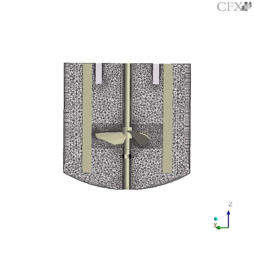
26 Figure 2
27 (a) MTTD, τ / t m = 6.80 Feeding-tube plane (b) MTTD, τ / t m = rotated plane 0.5 Vtip (c) MTTD, τ / t m = 3.76 Feeding-tube plane 0.5 Vtip 0.5 Vtip (d) MTTD, τ / t m = rotated plane (g) MTTD, batch (e) MTTD (2 inlets), τ / t m = 3.76 Feeding-tube plane (f) MTTD (2 inlets), τ / t m = rotated plane Figure 3
28 Power Number (P o ) MTTD, tau/tm τ / t m = 6.80 MTTD, tau/tm τ / t m = 3.76 MTTD 2I, tau/tm τ / t m = 3.76 MTTU, tau/tm τ / t m = 8.13 MTTU, tau/tm τ / t m = 4.50 MTTU 2I, tau/tm τ / t m = Position of impeller relative to inlet in degrees Figure 4
29 0.5 Vtip 0.5 Vtip (a) MTTU, τ / t m = 8.13 Feeding-tube plane (b) MTTD, τ / t m = rotated plane 0.5 Vtip 0.5 Vtip 0.5 Vtip (c) MTTU, τ / t m = 4.50 Feeding-tube plane (d) MTTU, τ / t m = rotated plane (g) MTTU, batch (e) MTTU (2inlets), τ / t m = 4.50 Feeding-tube plane 0.5Vtip (f) MTTU (2 inlets), τ / t m = rotated plane Figure 5
")

 MTTD, τ / t m = 3.")

 MTTD")

30 (a) MTTD, τ / t m = 6.80 Feeding-tube plane (b) MTTD, τ / t m = rotated plane C * = 0.195, σ = C * (c) MTTD, τ / t m = 3.76 Feeding-tube plane C * = 0.271, σ = (d) MTTD, τ / t m = rotated plane (c) MTTD (2 inlets), τ / t m = 3.76 Feeding-tube plane C * = 0.320, σ = (d) MTTD (2 inlets), τ / t m = rotated plane Figure 6

 MTTU, τ / t m = 8.")


 MTTU (2 inlets), τ / t m =")
 MTTU (2 inlets), τ / t")
31 (a) MTTU, τ / t m = 8.13 Feeding-tube plane C * = 0.169, σ = (b) MTTU, τ / t m = rotated plane C * (c) MTTU, τ / t m = 4.50 Feeding-tube plane C * = 0.292, σ = (d) MTTU, τ / t m = rotated plane (c) MTTU (2 inlets), τ / t m = 4.50 Feeding-tube plane C * = 0.288, σ = (d) MTTU (2 inlets), τ / t m = rotated plane Figure 7
32 z/dinlet = 1.4 z/dinlet = 2.4 z/dinlet = 3.4 z/dinlet = 4.4 z/dinlet = 5.4 Circular jet (Rajaratnam, 1976) z/dinlet = 1.4 z/dinlet = 2.4 z/dinlet = 3.4 z/dinlet = 4.4 z/dinlet = 5.4 Circular jet (Rajaratnam, 1976) U/U m ( - ) U/U m ( - ) η = r/b ( - ) (a) MTTD, τ / t m = 6.80 (inlet over blade) η = r/b ( - ) (b) MTTU, τ / t m = 8.13 (inlet over blade) z/dinlet = 1.4 z/dinlet = 2.4 z/dinlet = 3.4 z/dinlet = 4.4 z/dinlet = 5.4 Circular jet (Rajaratnam, 1976) z/dinlet = 1.4 z/dinlet = 2.4 z/dinlet = 3.4 z/dinlet = 4.4 z/dinlet = 5.4 Circular jet (Rajaratnam, 1976) U/U m ( - ) U/U m ( -) η = r/b ( - ) (c) MTTD τ / t m = 3.76 (inlet over blade) η = r/b ( -) (d) MTTU τ / t m = 4.50 (inlet over blade) z/dinlet = 1.4 z/dinlet = 2.4 z/dinlet = 3.4 z/dinlet = 4.4 z/dinlet = 5.4 Circular jet (Rajaratnum, 1976) z/dinlet = 1.4 z/dinlet = 2.4 z/dinlet = 3.4 z/dinlet = 4.4 z/dinlet = 5.4 Circular jet (Rajaratnam, 1976) U/Um ( - ) U/U m ( - ) η = r/b ( - ) (e) MTTD 2 inlets, τ / t m = 3.76, (inlet over blade) η = r/b ( - ) (f) MTTU 2 inlets, τ / t m = 4.50, (inlet over blade) z/dinlet = 1.4 z/dinlet = 2.4 z/dinlet = 3.4 z/dinlet = 4.4 z/dinlet = 5.4 Circular jet (Rajaratnum, 1976) z/dinlet = 1.4 z/dinlet = 2.4 z/dinlet = 3.4 z/dinlet = 4.4 z/dinlet = 5.4 Circular jet (Rajaratnam, 1976) U/Um ( - ) U/U m ( - ) η = r/b ( - ) (g) MTTD 2 inlets, τ / t m =3.76, (inlet between blades) η = r/b ( - ) (h) MTTU 2 inlets, τ / t m =4.50, (inlet between blades) Figure 8
33 b (m) b (m) MTTD, tau/tm τ / t m = 6.80 MTTD, tau/tm τ / t m = MTTD 2I, tau/tm τ / t m = 3.76 (inlet over blade) MTTD 2I, tau/tm τ / t m = 3.76 (inlet between blades) Circular jet (Rajaratnam, 1976) (z - zo) / dinlet ( (z z o )/d inlet ( - ) (a) MTTU, tau/tm τ / t m = 8.13 MTTU, tau/tm τ / t m = MTTU 2I, tau/tm τ / t m = 4.50 (inlet over blade) MTTU 2I, tau/tm τ / t m = 4.50 (inlet between blades) Circular jet (Rajaratnam, 1976) (z - zo)/dinlet (z z o )/d inlet ( - ) (b) U Um/Ucore m ( - ( ) - ) MTTD, tau/tm τ / t m = 6.80 MTTD, tau/tm τ / t m = 3.76 MTTD 2I, tau/tm τ / t m = 3.76 (inlet over blade) MTTD 2I, tau/tm τ / t m = 3.76 (inlet between blades) Circular jet (Rajaratnam, 1976) (z - zo) / dinlet ( (z z o )/d inlet ( - ) (c) U Um/Ucore m ( - ( ) - ) MTTU, tau/tm τ / t m = 8.13 MTTU, tau/tm τ / t m = 4.50 MTTU 2I, tau/tm τ / t m = 4.50, (inlet over blade) MTTU 2I, tau/tm τ / t m = 4.50, (inlet between blades) Circular jet (Rajaratnam, 1976) (z - zo) / dinlet (z z o )/d inlet ( - ) (d) Figure 9
Comparison of Different Techniques for Modelling of Flow Field and Homogenization in Stirred Vessels*
 Comparison of Different Techniques for Modelling of Flow Field and Homogenization in Stirred Vessels* M. MOŠTĚK**, A. KUKUKOVÁ, M. JAHODA, and V. MACHOŇ Department of Chemical Engineering, Faculty of Chemical
Study on residence time distribution of CSTR using CFD
 Indian Journal of Chemical Technology Vol. 3, March 16, pp. 114-1 Study on residence time distribution of CSTR using CFD Akhilesh Khapre*, Divya Rajavathsavai & Basudeb Munshi Department of Chemical Engineering,
NUMERICAL STUDY OF THE EFFECT OF BLADE SZE ON PUMPING EFFECTIVENESS OF A PADDLE IMPELLER IN AN UNBAFFLED MIXING VESSEL
 Third International Conference on CFD in the Minerals and Process Industries CSIRO, Melbourne, Australia 10-12 December 2003 NUMERICAL STUDY OF THE EFFECT OF BLADE SZE ON PUMPING EFFECTIVENESS OF A PADDLE
An Overview of Impellers, Velocity Profile and Reactor Design
 An Overview of s, Velocity Profile and Reactor Design Praveen Patel 1, Pranay Vaidya 1, Gurmeet Singh 2 1 Indian Institute of Technology Bombay, India 1 Indian Oil Corporation Limited, R&D Centre Faridabad
Flow Generated by Fractal Impeller in Stirred Tank: CFD Simulations
 Flow Generated by Fractal Impeller in Stirred Tank: CFD Simulations Gunwant M. Mule and Amol A. Kulkarni* Chem. Eng. & Proc. Dev. Division, CSIR-National Chemical Laboratory, Pune 411008, INDIA *Corresponding
PIV Measurements to Study the Effect of the Reynolds Number on the Hydrodynamic Structure in a Baffled. Vessel Stirred by a Rushton Turbine
 American Journal of Energy Research, 2014, Vol. 2, No. 3, 67-73 Available online at http://pubs.sciepub.com/ajer/2/3/4 Science and Education Publishing DOI:10.12691/ajer-2-3-4 PIV Measurements to Study
Effect of the Tank Design on the Flow Pattern Generated with a Pitched Blade Turbine
 International Journal of Mechanics and Applications 2012, 2(1): 12-19 DOI: 10.5923/j.mechanics.20120201.03 Effect of the Tank Design on the Flow Pattern Generated with a Pitched Blade Turbine M. Ammar,
PIV MEASUREMENTS AND CFD SIMULATION OF VISCOUS FLUID FLOW IN A STIRRED TANK AGITATED BY A RUSHTON TURBINE
 Fifth International Conference on CFD in the Process Industries CSIRO, Melbourne, Australia 3-5 December 26 PIV MEASUREMENTS AND CFD SIMULATION OF VISCOUS FLUID FLOW IN A STIRRED TANK AGITATED BY A RUSHTON
CFD ANALYSIS OF TURBULENCE EFFECT ON REACTION IN STIRRED TANK REACTORS
 CFD ANALYSIS OF TURBULENCE EFFECT ON REACTION IN STIRRED TANK REACTORS Udaya Bhaskar Reddy R*, Gopalakrishnan S, Ramasamy E Department of Chemical Engineering, Coimbatore Institute of Technology, Coimbatore-
PLO MIXING AND RTD IN TANKS: RADIOTRACER EXPERIMENTS AND CFD SIMULATIONS
 PLO522 MIXING AND RTD IN TANKS: RADIOTRACER EXPERIMENTS AND CFD SIMULATIONS A. R. Thatte and A. W. Patwardhan Institute of Chemical Techno lou Uiversity of Mumhai, Mumbai, India H. J. PantV. K. Sharma,
Flow analysis in centrifugal compressor vaneless diffusers
 348 Journal of Scientific & Industrial Research J SCI IND RES VOL 67 MAY 2008 Vol. 67, May 2008, pp. 348-354 Flow analysis in centrifugal compressor vaneless diffusers Ozturk Tatar, Adnan Ozturk and Ali
Application of the CFD method for modelling of floating particles suspension
 Application of the CFD method for modelling of floating particles suspension Joanna Karcz, Lukasz Kacperski, Marcelina Bitenc Szczecin University of Technology, Dept. of Chem. Eng. al. Piastow 42, PL-7-65
The ow characteristics of a novel agitator, termed Narcissus (NS), have been
, have been") 0263 8762/01/$10.00+0.00 # Institution of Chemical Engineers EXPERIMENTAL VISUALIZATION AND CFD SIMULATION OF FLOW PATTERNS INDUCED BY A NOVEL ENERGY-SAVING DUAL-CONFIGURATION IMPELLER IN STIRRED VESSELS*
0263 8762/01/$10.00+0.00 # Institution of Chemical Engineers EXPERIMENTAL VISUALIZATION AND CFD SIMULATION OF FLOW PATTERNS INDUCED BY A NOVEL ENERGY-SAVING DUAL-CONFIGURATION IMPELLER IN STIRRED VESSELS*
Dynamic Effect of Discharge Flow of a Rushton Turbine Impeller on a Radial Baffle J. Kratěna, I. Fořt, O. Brůha
 Dynamic Effect of Discharge Flow of a Rushton Turbine Impeller on a Radial Baffle J. Kratěna, I. Fořt, O. Brůha This paper presents an analysis of the mutual dynamic relation between the impeller discharge
Effect of Baffles Geometry on Hydrodynamics in a Mechanically Agitated System
 Effect of Baffles Geometry on Hydrodynamics in a Mechanically Agitated System L. Benyamina 1, M. Bouanini 2 and R. Abdeldjebar 3 1 PhD in Physics Energetics, 2 Doctor in Energy Physics, 3 Magister Energy
Blade Angle Effects on the Flow in a Tank Agitated by the Pitched-Blade Turbine
 Yeng-Yung Tsui 1 Professor e-mail: yytsui@mail.nctu.edu.tw Jian-Ren Chou Graduate Student Yu-Chang Hu Graduate Student Department of Mechanical Engineering, National Chiao Tung University, Hsinchu 300,
1. Starting of a project and entering of basic initial data.
 PROGRAM VISIMIX TURBULENT SV. Example 1. Contents. 1. Starting of a project and entering of basic initial data. 1.1. Opening a Project. 1.2. Entering dimensions of the tank. 1.3. Entering baffles. 1.4.
CHAPTER 7 NUMERICAL MODELLING OF A SPIRAL HEAT EXCHANGER USING CFD TECHNIQUE
 CHAPTER 7 NUMERICAL MODELLING OF A SPIRAL HEAT EXCHANGER USING CFD TECHNIQUE In this chapter, the governing equations for the proposed numerical model with discretisation methods are presented. Spiral
CFD SIMULATIONS OF SINGLE AND TWO-PHASE MIXING PROESSES IN STIRRED TANK REACTORS
 CFD SIMULATIONS OF SINGLE AND TWO-PHASE MIXING PROESSES IN STIRRED TANK REACTORS Hristo Vesselinov Hristov, Stephan Boden, Günther Hessel, Holger Kryk, Horst-Michael Prasser, and Wilfried Schmitt. Introduction
CFD STUDY OF MASS TRANSFER IN SPACER FILLED MEMBRANE MODULE
 GANIT J. Bangladesh Math. Soc. (ISSN 1606-3694) 31 (2011) 33-41 CFD STUDY OF MASS TRANSFER IN SPACER FILLED MEMBRANE MODULE Sharmina Hussain Department of Mathematics and Natural Science BRAC University,
Chaos in mixing vessels
 Chaos in mixing vessels Pavel Hasal and Ivan Fořt 2 Institute of Chemical Technology, Prague Department of Chemical Engineering CZ-66 28 Praha 6, Czech Republic (e-mail: Pavel.Hasal@vscht.cz) 2 Czech Technical
Mixing Performance of Counter-Axial Flow Impeller using Computational Fluid Dynamics
 International Journal of Current Engineering and Technology E-ISSN 2277 4106, P-ISSN 2347 5161 2018 INPRESSCO, All Rights Reserved Available at http://inpressco.com/category/ijcet Research Article Mixing
Numerical Simulation of the Evolution of Reynolds Number on Laminar Flow in a Rotating Pipe
 American Journal of Fluid Dynamics 2014, 4(3): 79-90 DOI: 10.5923/j.ajfd.20140403.01 Numerical Simulation of the Evolution of Reynolds Number on Laminar Flow in a Rotating Pipe A. O. Ojo, K. M. Odunfa,
CFD SIMULATION OF SOLID-LIQUID STIRRED TANKS
 CFD SIMULATION OF SOLID-LIQUID STIRRED TANKS Divyamaan Wadnerkar 1, Ranjeet P. Utikar 1, Moses O. Tade 1, Vishnu K. Pareek 1 Department of Chemical Engineering, Curtin University Perth, WA 6102 r.utikar@curtin.edu.au
EVALUATION OF FOUR TURBULENCE MODELS IN THE INTERACTION OF MULTI BURNERS SWIRLING FLOWS
 EVALUATION OF FOUR TURBULENCE MODELS IN THE INTERACTION OF MULTI BURNERS SWIRLING FLOWS A Aroussi, S Kucukgokoglan, S.J.Pickering, M.Menacer School of Mechanical, Materials, Manufacturing Engineering and
PHEN 612 SPRING 2008 WEEK 12 LAURENT SIMON
 PHEN 612 SPRING 28 WEEK 12 LAURENT SIMON Mixing in Reactors Agitation, Mixing of Fluids and Power requirements Agitation and mixing are two of the most common operations in the processing industries Agitation:
Effect of a Continuous Feed on the Fluid-Dynamics of a Mechanically Stirred Tank
 1609 A publication of CHEMICAL ENGINEERING TRANSACTIONS VOL. 43, 2015 Chief Editors: Sauro Pierucci, Jiří J. Klemeš Copyright 2015, AIDIC Servizi S.r.l., ISBN 978-88-95608-34-1; ISSN 2283-9216 The Italian
Liquid Mixing in Agitated Vessels
 100 5 Liquid Mixing in Agitated essels To express the degree of mixing in a stirred vessel, an expression is desirable to show how far the state of mixing deviates from the ideal complete mixing. The most
THE VELOCITY FIELD IN THE DISCHARGE STREAM FROM A RUSHTON TURBINE IMPELLER
 4 th European Conference on Mixing Warszawa, September THE VELOCITY FIELD IN THE DISCHARGE STREAM FROM A RUSHTON TURBINE IMPELLER Jan Talaga a, Ivan Fořt b a Cracow University of Technology, Institute
AN INVESTIGATION INTO DIFFERENT POWER CONSUMPTION PARAMETERS OF RUSHTON TURBINES: A COMPUTATIONAL SURVEY
 Mohammad-Reza Ashory Farhad Talebi Heydar Roohi Ghadikolaei Morad Karimpour https://doi.org/10.21278/tof.41404 ISSN 1333-1124 eissn 1849-1391 AN INVESTIGATION INTO DIFFERENT POWER CONSUMPTION PARAMETERS
APPLICATION OF MODELS WITH DIFFERENT COMPLEXITY FOR A STIRRED TANK REACTOR
 HUNGARIAN JOURNAL OF INDUSTRIAL CHEMISTRY VESZPRÉM Vol. 39(3) pp. 335-339 (011) APPLICATION OF MODELS WITH DIFFERENT COMPLEXITY FOR A STIRRED TANK REACTOR A. EGEDY, T. VARGA, T. CHOVÁN University of Pannonia,
EFFECT OF DISTRIBUTION OF VOLUMETRIC HEAT GENERATION ON MODERATOR TEMPERATURE DISTRIBUTION
 EFFECT OF DISTRIBUTION OF VOLUMETRIC HEAT GENERATION ON MODERATOR TEMPERATURE DISTRIBUTION A. K. Kansal, P. Suryanarayana, N. K. Maheshwari Reactor Engineering Division, Bhabha Atomic Research Centre,
ENGG 199 Reacting Flows Spring Lecture 4 Gas-Liquid Mixing Reactor Selection Agitator Design
 ENGG 199 Reacting Flows Spring 2006 Lecture 4 Gas-Liquid Mixing Reactor Selection gitator Design Copyright 2000,.W. Etchells, R.K.Grenville & R.D. LaRoche ll rights reserved. Background Roughly 25 % of
Application of COMSOL Multiphysics in Transport Phenomena Educational Processes
 Application of COMSOL Multiphysics in Transport Phenomena Educational Processes M. Vasilev, P. Sharma and P. L. Mills * Department of Chemical and Natural Gas Engineering, Texas A&M University-Kingsville,
SIMULATION OF PRECESSION IN AXISYMMETRIC SUDDEN EXPANSION FLOWS
 Second International Conference on CFD in the Minerals and Process Industries CSIRO, Melbourne, Australia 6-8 December 1999 SIMULATION OF PRECESSION IN AXISYMMETRIC SUDDEN EXPANSION FLOWS Baoyu GUO, Tim
A NUMERICAL ANALYSIS OF COMBUSTION PROCESS IN AN AXISYMMETRIC COMBUSTION CHAMBER
 SCIENTIFIC RESEARCH AND EDUCATION IN THE AIR FORCE-AFASES 2016 A NUMERICAL ANALYSIS OF COMBUSTION PROCESS IN AN AXISYMMETRIC COMBUSTION CHAMBER Alexandru DUMITRACHE*, Florin FRUNZULICA ** *Institute of
PARTICLE IMAGE VELOCIMETRY MEASUREMENTS IN AN AERATED STIRRED TANK
 Chem. Eng. Comm., 189: 1208 1221, 2002 Copyright # 2002 Taylor & Francis 0098-6445/02 $12.00 +.00 DOI: 10.1080=00986440290012582 PARTICLE IMAGE VELOCIMETRY MEASUREMENTS IN AN AERATED STIRRED TANK NIELS
Nirma University Institute of Technology Chemical Engineering Department, Handouts -RRP- CRE-II. Handouts
 Handouts Handout 1: Practical reactor performance deviates from that of ideal reactor s : Packed bed reactor Channeling CSTR & Batch Dead Zones, Bypass PFR deviation from plug flow dispersion Deviation
Calculation of Power, Shear and Gas-liquid mass transfer in reactors for fermentation.
 VISIMIX TURBULENT. GAS-LIQUID MIXING. FERMENTATION. Calculation of Power, Shear and Gas-liquid mass transfer in reactors for fermentation. 1. Subject of calculations and initial data. This example demonstrates
DEVELOPMENT OF CFD MODEL FOR A SWIRL STABILIZED SPRAY COMBUSTOR
 DRAFT Proceedings of ASME IMECE: International Mechanical Engineering Conference & Exposition Chicago, Illinois Nov. 5-10, 2006 IMECE2006-14867 DEVELOPMENT OF CFD MODEL FOR A SWIRL STABILIZED SPRAY COMBUSTOR
International Journal of Scientific & Engineering Research, Volume 6, Issue 5, May ISSN
 International Journal of Scientific & Engineering Research, Volume 6, Issue 5, May-2015 28 CFD BASED HEAT TRANSFER ANALYSIS OF SOLAR AIR HEATER DUCT PROVIDED WITH ARTIFICIAL ROUGHNESS Vivek Rao, Dr. Ajay
THE DETAILS OF THE TURBULENT FLOW FIELD IN THE VICINITY OF A RUSHTON TURBINE
 14 th European Conference on Mixing Warszawa, 10-13 September 2012 THE DETAILS OF THE TURBULENT FLOW FIELD IN THE VICINITY OF A RUSHTON TURBINE Harry E.A. Van den Akker Kramers Laboratorium, Dept. of Multi-Scale
NUMERICAL SIMULATION OF FLUID FLOW BEHAVIOUR ON SCALE UP OF OSCILLATORY BAFFLED COLUMN
 Journal of Engineering Science and Technology Vol. 7, No. 1 (2012) 119-130 School of Engineering, Taylor s University NUMERICAL SIMULATION OF FLUID FLOW BEHAVIOUR ON SCALE UP OF OSCILLATORY BAFFLED COLUMN
Characterization of Laminar Flow and Power Consumption in a Stirred Tank by a Curved Blade Agitator
 Proceedings of the International Conference on Heat Transfer and Fluid Flow Prague, Czech Republic, August 11-12, 2014 Paper No. 11 Characterization of Laminar Flow and Power Consumption in a Stirred Tank
CFD Analysis of a Stirred Vessel Bioreactor with Double Pitch Blade and Rushton Type Impellers
 CFD Analysis of a Stirred Vessel Bioreactor with Double Pitch Blade and Rushton Type Impellers A. Buss 1, 2, A. Suleiko 2, 3, K. Rugele 2, J. Vanags 3 1. Riga Biomaterials Innovation and Development Centre,
INFLUENCE OF VAPOR FEED DESIGN ON THE FLOW DISTRIBUTION
 INFLUENCE OF VAPOR FEED DESIGN ON THE FLOW DISTRIBUTION M. Wehrli *, S. Hirschberg**, R. Schweizer** * Sulzer Chemtech AG, Postfach, CH-8404 Winterthur, Switzerland ** Sulzer Innotec AG, Postfach, CH-8401
Effect of Geometry on the Mechanisms for Off-Bottom Solids Suspension in a Stirred Tank
 Effect of Geometry on the Mechanisms for Off-Bottom Solids Suspension in a Stirred Tank Inci Ayranci 1*, Márcio B. Machado 1, Adam M. Madej 2, Jos J. Derksen 1, David S. Nobes 2, and Suzanne M. Kresta
arxiv: v1 [physics.flu-dyn] 11 Oct 2012
![arxiv: v1 [physics.flu-dyn] 11 Oct 2012](/thumbs/94/118739408.jpg "arxiv: v1 [physics.flu-dyn] 11 Oct 2012") Low-Order Modelling of Blade-Induced Turbulence for RANS Actuator Disk Computations of Wind and Tidal Turbines Takafumi Nishino and Richard H. J. Willden ariv:20.373v [physics.flu-dyn] Oct 202 Abstract
Low-Order Modelling of Blade-Induced Turbulence for RANS Actuator Disk Computations of Wind and Tidal Turbines Takafumi Nishino and Richard H. J. Willden ariv:20.373v [physics.flu-dyn] Oct 202 Abstract
Intensely swirling turbulent pipe flow downstream of an orifice: the influence of an outlet contraction
 13 th Int. Symp. on Appl. Laser Techniques to Fluid Mechanics, Lisbon, Portugal, June 26-29, 26 Intensely swirling turbulent pipe flow downstream of an orifice: the influence of an outlet contraction Marcel
Turbulent Boundary Layers & Turbulence Models. Lecture 09
 Turbulent Boundary Layers & Turbulence Models Lecture 09 The turbulent boundary layer In turbulent flow, the boundary layer is defined as the thin region on the surface of a body in which viscous effects
mixing of fluids MIXING AND AGITATION OF FLUIDS
 Levenspiel [2] considered when two fluids are mixed together, the molecular behavior of the dispersed fluid falls between two extremes. If molecules are completely free to move about, the dispersed fluid
FLOW CHARACTERISTICS IN A VOLUTE-TYPE CENTRIFUGAL PUMP USING LARGE EDDY SIMULATION
 FLOW CHARACTERISTICS IN A VOLUTE-TYPE CENTRIFUGAL PUMP USING LARGE EDDY SIMULATION Beomjun Kye Keuntae Park Department of Mechanical & Aerospace Engineering Department of Mechanical & Aerospace Engineering
Wall Effects in Convective Heat Transfer from a Sphere to Power Law Fluids in Tubes
 Excerpt from the Proceedings of the COMSOL Conference 9 Boston Wall Effects in Convective Heat Transfer from a Sphere to Power Law Fluids in Tubes Daoyun Song *1, Rakesh K. Gupta 1 and Rajendra P. Chhabra
AGITATION AND AERATION
 AGITATION AND AERATION Although in many aerobic cultures, gas sparging provides the method for both mixing and aeration - it is important that these two aspects of fermenter design be considered separately.
CFD Analysis of Forced Convection Flow and Heat Transfer in Semi-Circular Cross-Sectioned Micro-Channel
 CFD Analysis of Forced Convection Flow and Heat Transfer in Semi-Circular Cross-Sectioned Micro-Channel *1 Hüseyin Kaya, 2 Kamil Arslan 1 Bartın University, Mechanical Engineering Department, Bartın, Turkey
EVALUATION OF THE EFFECT OF PITCHED BLADE TURBINE ON MIXING IN AN ELECTROCHEMICAL REACTOR WITH ROTATING RING ELECTRODES.
 EVALUATION OF THE EFFECT OF PITCHED BLADE TURBINE ON MIXING IN AN ELECTROCHEMICAL REACTOR WITH ROTATING RING ELECTRODES. Sergio A. Martinez, Universidad Autónoma Metropolitana, México D.F. Mex., Jorge
Evaluation and accuracy of the local velocity data measurements in an agitated vessel
 EPJ Web of Conferences 67, 02065 (2014) DOI: 10.1051/ epjconf/20146702065 C Owned by the authors, published by EDP Sciences, 2014 Evaluation and accuracy of the local velocity data measurements in an agitated
Experimental identification of the flow vortex structures generated in the agitated vessels
 Experimental identification of the flow vortex structures generated in the agitated vessels D. JASIKOVA, B. KYSELA, M. KOTEK, V. KOPECKY Institute for Nanomaterials, Advanced Technologies and Innovation
On the transient modelling of impinging jets heat transfer. A practical approach
 Turbulence, Heat and Mass Transfer 7 2012 Begell House, Inc. On the transient modelling of impinging jets heat transfer. A practical approach M. Bovo 1,2 and L. Davidson 1 1 Dept. of Applied Mechanics,
AN OVERVIEW OF IMPELLERS, VELOCITY PROFILES AND REACTOR DESIGN
 AN OVERVIEW OF IMPELLERS, VELOCITY PROFILES AND REACTOR DESIGN Instructor: Gurmeet Singh (Department Manager of Polymer and Processing Department IOCL R&D center, Faridabad) 1 Presented by: Pranay. K.
Investigation of Flow Profile in Open Channels using CFD
 Investigation of Flow Profile in Open Channels using CFD B. K. Gandhi 1, H.K. Verma 2 and Boby Abraham 3 Abstract Accuracy of the efficiency measurement of a hydro-electric generating unit depends on the
Large eddy simulations of flow instabilities in a stirred tank generated by a Rushton turbine *
 Large eddy simulations of flow instabilities in a stirred tank generated by a Rushton turbine * FAN Jianhua ( 樊建华 ) a,b, WANG undong ( 王运东 ) a, FEI Weiyang ( 费维扬 ) a a The State Key Laboratory of Chemical
PARTICLE SUSPENSION WITH A TX445 IMPELLER
 4 th European Conference on Mixing Warszawa, -3 September 22 PARTICLE SUSPENSION WITH A IMPELLER František Rieger, Dorin Ceres, Pavel Seichter 2 Czech Technical University in Prague, Faculty of Mechanical
Modeling of turbulence in stirred vessels using large eddy simulation
 Modeling of turbulence in stirred vessels using large eddy simulation André Bakker (presenter), Kumar Dhanasekharan, Ahmad Haidari, and Sung-Eun Kim Fluent Inc. Presented at CHISA 2002 August 25-29, Prague,
CHAPTER 3 MODELLING AND ANALYSIS OF THE PACKED COLUMN
 37 CHAPTER 3 MODELLING AND ANALYSIS OF THE PACKED COLUMN Absorption in a chemical process refers to a mass transfer between gas and liquid which transfers one or more components from the gas phase to the
Simplified Model of WWER-440 Fuel Assembly for ThermoHydraulic Analysis
 1 Portál pre odborné publikovanie ISSN 1338-0087 Simplified Model of WWER-440 Fuel Assembly for ThermoHydraulic Analysis Jakubec Jakub Elektrotechnika 13.02.2013 This work deals with thermo-hydraulic processes
CFD modelling of lab-scale anaerobic digesters to determine experimental sampling locations
 CFD modelling of lab-scale anaerobic digesters to determine experimental sampling locations Rebecca Sindall 1, John Bridgeman 1 and Cynthia Carliell-Marquet 1 1 School of Civil Engineering, University
WM2013 Conference, February 24 28, 2013, Phoenix, Arizona USA
 Comparison Between Numerical and Experimental Results on Mechanical Stirrer and Bubbling in a Cylindrical Tank 13047 M. Lima da Silva* 1, A. Gagnoud**, Y. Fautrelle**, E. Sauvage*, P. Brun* and R. Riva***
Turbulence Characteristics in a Rushton Stirring Vessel: A Numerical Investigation
 urbulence Characteristics in a Rushton Stirring Vessel: A Numerical Investigation Mohammad Amin Rashidifar 1 and Ali Amin Rashidifar 2 1 Department of Mechanical Engineering, Islamic Azad University, Shadegan
Analysis of the Cooling Design in Electrical Transformer
 Analysis of the Cooling Design in Electrical Transformer Joel de Almeida Mendes E-mail: joeldealmeidamendes@hotmail.com Abstract This work presents the application of a CFD code Fluent to simulate the
Power requirements for yield stress fluids in a vessel with forward-reverse rotating impeller
 Available online at www.sciencedirect.com Procedia Engineering 42 (2012 ) 1437 1444 20 th International Congress of Chemical and Process Engineering CHISA 2012 25 29 August 2012, Prague, Czech Republic
Comparison of Agitators Performance for Particle Suspension in Top-Covered Unbaffled Vessels
 585 A publication of CHEMICAL ENGINEERING TRANSACTIONS VOL. 43, 205 Chief Editors: Sauro Pierucci, Jiří J. Klemeš Copyright 205, AIDIC Servizi S.r.l., ISBN 978-88-95608-34-; ISSN 2283-926 The Italian Association
Reduced mixing time in stirred vessels by means of irregular impellers
 Reduced mixing time in stirred vessels by means of irregular impellers S. Başbuğ, G. Papadakis and J. C. Vassilicos Department of Aeronautics, Imperial College London, SW7 2AZ London, UK Abstract Previous
AGITATION/GAS-LIQUID DISPERSION. CHEM-E Fluid Flow in Process Units
 AGITATION/GAS-LIQUID DISPERSION CHEM-E7160 - Fluid Flow in Process Units 1. INTRODUCTION Agitation: Mixing: Blending: Suspension: Dispersion: Induced motion of a material in a specific way, usually in
CFD STUDIES IN THE PREDICTION OF THERMAL STRIPING IN AN LMFBR
 CFD STUDIES IN THE PREDICTION OF THERMAL STRIPING IN AN LMFBR K. Velusamy, K. Natesan, P. Selvaraj, P. Chellapandi, S. C. Chetal, T. Sundararajan* and S. Suyambazhahan* Nuclear Engineering Group Indira
GENERALISATION OF THE TWO-SCALE MOMENTUM THEORY FOR COUPLED WIND TURBINE/FARM OPTIMISATION
 25 th National Symposium on Wind Engineering, Tokyo, Japan, 3-5 December 2018 第 25 回風工学シンポジウム (2018) GENERALISATION OF THE TWO-SCALE MOMENTUM THEORY FOR COUPLED WIND TURBINE/FARM OPTIMISATION Takafumi
RELATION BETWEEN PARTICLE RISING BEHAVIOR AND LIQUID FLOW AROUND THE BOTTOM OF A STIRRED VESSEL
 14 th European Conference on Mixing Warszawa, 10-13 September 2012 RELATION BETWEEN PARTICLE RISING BEHAVIOR AND LIQUID FLOW AROUND THE BOTTOM OF A STIRRED VESSEL Ryuta Misumi a, Takuji Sasaki b, Hayato
Manhar Dhanak Florida Atlantic University Graduate Student: Zaqie Reza
 REPRESENTING PRESENCE OF SUBSURFACE CURRENT TURBINES IN OCEAN MODELS Manhar Dhanak Florida Atlantic University Graduate Student: Zaqie Reza 1 Momentum Equations 2 Effect of inclusion of Coriolis force
Active Control of Separated Cascade Flow
 Chapter 5 Active Control of Separated Cascade Flow In this chapter, the possibility of active control using a synthetic jet applied to an unconventional axial stator-rotor arrangement is investigated.
Numerical Prediction Of Torque On Guide Vanes In A Reversible Pump-Turbine
 Journal of Multidisciplinary Engineering Science and Technology (JMEST) ISSN: 3159 Vol. 2 Issue 6, June - 215 Numerical Prediction Of Torque On Guide Vanes In A Reversible Pump-Turbine Turbine and pump
Effect of Shape and Flow Control Devices on the Fluid Flow Characteristics in Three Different Industrial Six Strand Billet Caster Tundish
 , pp. 1647 1656 Effect of Shape and Flow Control Devices on the Fluid Flow Characteristics in Three Different Industrial Six Strand Billet Caster Tundish Anurag TRIPATHI and Satish Kumar AJMANI Research
Estimation of Agitator Flow Shear Rate
 Estimation of Agitator Flow Shear Rate Jie Wu, Lachlan J. Graham, and Nabil Noui Mehidi Fluids Engineering Research Laboratory, Commonwealth Scientific and Industrial Research Organization (CSIRO), Highett
Chemical Reaction Engineering
 Lecture 32! Chemical Reaction Engineering (CRE) is the field that studies the rates and mechanisms of chemical reactions and the design of the reactors in which they take place.!! 1! Lecture 32 Thursday
Computational Fluid Dynamics Modelling of Natural Convection in Copper Electrorefining
 16 th Australasian Fluid Mechanics Conference Crown Plaza, Gold Coast, Australia 2-7 December 2007 Abstract Computational Fluid Dynamics Modelling of Natural Convection in Copper Electrorefining A computational
INVESTIGATION OF SWIRLING FLOW IN DIFFUSERS INSTALLED AT THE EXIT OF AN AXIAL-FLOW PUMP
 TASK QUARTERLY 5 No 4 (2001), 603 610 INVESTIGATION OF SWIRLING FLOW IN DIFFUSERS INSTALLED AT THE EXIT OF AN AXIAL-FLOW PUMP ALEXEY N. KOCHEVSKY Department of Fluid Mechanics, Sumy State University, Rimsky-Korsakov
CFD analysis of the transient flow in a low-oil concentration hydrocyclone
 CFD analysis of the transient flow in a low-oil concentration hydrocyclone Paladino, E. E. (1), Nunes, G. C. () and Schwenk, L. (1) (1) ESSS Engineering Simulation and Scientific Software CELTA - Rod SC-41,
COMPUTATIONAL FLOW ANALYSIS THROUGH A DOUBLE-SUCTION IMPELLER OF A CENTRIFUGAL PUMP
 Proceedings of the Fortieth National Conference on Fluid Mechanics and Fluid Power December 12-14, 2013, NIT Hamirpur, Himachal Pradesh, India FMFP2013_141 COMPUTATIONAL FLOW ANALYSIS THROUGH A DOUBLE-SUCTION
Numerical and Experimental Investigation of the Flow in a Centrifugal Pump Stage
 Numerical and Experimental Investigation of the Flow in a Centrifugal Pump Stage FRIEDRICH-KARL BENRA, HANS JOSEF DOHMEN Faculty of Engineering Sciences Department of Mechanical Engineering, Turbomachinery
CFD SIMULATION OF A SINGLE PHASE FLOW IN A PIPE SEPARATOR USING REYNOLDS STRESS METHOD
 CFD SIMULATION OF A SINGLE PHASE FLOW IN A PIPE SEPARATOR USING REYNOLDS STRESS METHOD Eyitayo A. Afolabi 1 and J. G. M. Lee 2 1 Department of Chemical Engineering, Federal University of Technology, Minna,
Assessing Mixing Sensitivities for Scale-up. Matthew Jörgensen Atlanta, 10/20/2014
 Assessing Mixing Sensitivities for Scale-up Matthew Jörgensen Atlanta, 10/20/2014 Nalas: Solutions that Scale! Engineering Services Broad range of services & capabilities supporting chemical process development
EffectofBaffleDesignontheOff-bottomSuspensionCharacteristics ofaxial-flowimpellersinapilot-scalemixingvessel
 M. ŠPIDLA et al., Effect of Baffle Design on the Off-bottom Suspension, Chem. Biochem. Eng. Q. 19 (4) 333 340 (2005) 333 EffectofBaffleDesignontheOff-bottomSuspensionCharacteristics ofaxial-flowimpellersinapilot-scalemixingvessel
THINK FLUID DYNAMIX Mixing, Homogenization & Blend Time. THINK Fluid Dynamix
 THINK FLUID DYNAMIX Mixing, Homogenization & Blend Time Provided by: THINK Fluid Dynamix Am Pestalozziring 21 D-91058 Erlangen (Germany) Tel. +49 (0)9131 69098-00 http://www.think-fd.com CFD ENGINEERING
Characterization of Trailing Vortices Generated by a Rushton Turbine
 Characterization of Trailing Vortices Generated by a Rushton Turbine Renaud Escudié, Denis Bouyer, and Alain Liné Laboratoire d Ingénierie des Procédés de l Environnement, Institut National des Sciences
PIV Study of the Turbulent Flow in a Stirred Vessel Equipped by an Eight Concave Blades Turbine
 Fluid Mechanics 2015; 1(2): 5-10 Published online August 31, 2015 (http://www.sciencepublishinggroup.com/j/fm) doi: 10.11648/j.fm.20150102.11 PIV Study of the Turbulent Flow in a Stirred Vessel Equipped
ARTICLE IN PRESS. chemical engineering research and design x x x ( ) xxx xxx. Contents lists available at ScienceDirect
 xxx xxx. Contents lists available at ScienceDirect") chemical engineering research and design x x x (2 0 0 9) xxx xxx Contents lists available at ScienceDirect Chemical Engineering Research and Design journal homepage: www.elsevier.com/locate/cherd Ekman
chemical engineering research and design x x x (2 0 0 9) xxx xxx Contents lists available at ScienceDirect Chemical Engineering Research and Design journal homepage: www.elsevier.com/locate/cherd Ekman
Performance characteristics of turbo blower in a refuse collecting system according to operation conditions
 Journal of Mechanical Science and Technology 22 (2008) 1896~1901 Journal of Mechanical Science and Technology www.springerlink.com/content/1738-494x DOI 10.1007/s12206-008-0729-6 Performance characteristics
Buoyancy driven turbulent flow and experimental validation at the VeMix test facility
 Applied and Computational Mechanics 1 (2007) 677-684 Buoyancy driven turbulent flow and experimental validation at the VeMix test facility R. Vaibar a,, M. J. Da Silva a, T. Sühnel a a Forschungszentrum
Numerical Study of Hydrodynamics in an External-Loop Air-Lift Reactor
 Numerical Study of Hydrodynamics in an External-Loop Air-Lift Reactor Joanna Karcz *, Marcelina Bitenc, Marek Domański, Łukasz Kacperski West Pomeranian University of Technology, Szczecin, Dept. of Chem.
Flow Structure Investigations in a "Tornado" Combustor
 Flow Structure Investigations in a "Tornado" Combustor Igor Matveev Applied Plasma Technologies, Falls Church, Virginia, 46 Serhiy Serbin National University of Shipbuilding, Mikolayiv, Ukraine, 545 Thomas
Effect of Static Magnetic Field Application on the Mass Transfer in Sequence Slab Continuous Casting Process
 , pp. 844 850 Effect of Static Magnetic Field Application on the Mass Transfer in Sequence Slab Continuous Casting Process Baokuan LI and Fumitaka TSUKIHASHI 1) Department of Thermal Engineering, The School