SHORTCUT CALCULATIONS AND GRAPHICAL COMPRESSOR SELECTION PROCEDURES
|
|
|
- Marion Kelly
- 5 years ago
- Views:
Transcription
1 APPENDIX B SHORTCUT CALCULATIONS AND GRAPHICAL COMPRESSOR SELECTION PROCEDURES B.1 SELECTION GUIDE FOR ELLIOTT MULTISTAGE CENTRIFUGAL COMPRESSORS* * Reprinted from a 1994 Elliott Company sales bulletin. The reference information contained herein is provided as an assist to developing your application. However, Elliott reserves the right to modify the design or construction of the equipment described and to furnish it, as altered, without further reference to the illustrations or information contained herein. A Practical Guide to Compressor Technology, Second Edition, By Heinz P. Bloch Copyright 2006 John Wiley & Sons, Inc. 507
2 508 APPENDIX B
3 SHORTCUT CALCULATIONS AND SELECTION PROCEDURES 509
4 510 APPENDIX B
5 SHORTCUT CALCULATIONS AND SELECTION PROCEDURES 511
6 512 APPENDIX B
7 SHORTCUT CALCULATIONS AND SELECTION PROCEDURES 513
8 514 APPENDIX B
9
10 516 APPENDIX B


11 SHORTCUT CALCULATIONS AND SELECTION PROCEDURES 517

12 518 APPENDIX B
13 SHORTCUT CALCULATIONS AND SELECTION PROCEDURES 519
14 520 APPENDIX B
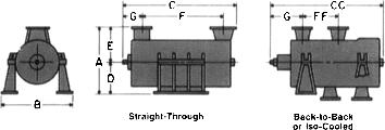
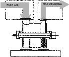
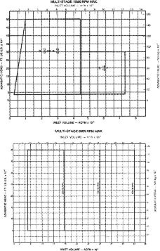
15 SHORTCUT CALCULATIONS AND SELECTION PROCEDURES 521 B.2 QUICK SELECTION METHODS FOR MULTISTAGE COMPRESSORS* Among the many purely graphical methods of rapidly selecting multistage compressors is one developed around 1965 by Don Hallock of the Elliott Company, Jeannette, Pa. To use these charts, the following quantities must be known: 1. W weight flow, in lb/min or scfm (standard ft 3 /min). 2. P 1 inlet pressure, in psia 3. R p pressure ratio (discharge psia/inlet psia) 4. t 1 inlet temp., in F 5. M mole weight 6. K ratio of specific heats Determine the Inlet cfm, Q1. If W is known, use Fig. B.1, proceeding through P 1, t 1, and M to find Q 1. If scfm is known, use Fig. B.2, proceeding through P 1, t 1, and temperature standard to find Q 1. Determine the Head H. On Fig. B.3, enter R p and proceed through K, t 1, and M as shown. If head H exceeds 80,000 to 90,000, more than one compressor body will be required. Determine the Number of Stages Required. On Fig. B.4, enter head H and proceed through M to read the number of stages required. Round this off to the next-higher even number. Determine the Speed and Size of the Machine. On Fig. B.5, enter Q 1 and read the maximum width in inches. Proceed to the stepped lines and read the rpm and flange sizes. Proceed through the number of stages and read the length of the machine in inches. In the example shown, the icfm is 45,000 and the gas is between propane and chlorine in mole weight. The speed is shown to be 4000 rpm and the flanges are 36 and 24 in. A slightly higher flow requires 3500 rpm and 42- and 30-in. flanges. Determine the Horsepower Requirement. On Fig. B.6, enter W, proceed through Q 1 and H, and read HP. If W is not known, work backward from Q 1 on Fig. B.1 to find W before using Fig. B.6. For uncooled, constant weight flow compression, such as alkylation, wet gas, recycle, or air under 50 psia, the foregoing is sufficient to determine price, size, and driver requirement. For cooled or variable weight flow compression, proceed as follows: Cooled Compression. Assume one cooler and two compression sections, each section handling a pressure ratio equal to the square root of the overall pressure ratio. Determine discharge temperature t 2 from Fig. B.7, proceeding through R p, Q 1, K, and t 1. Assuming that this t 2 is satisfactory, proceed through all the figures for each of the separate sections. Speed and width of the compressor will be dictated by the first sections. The total horsepower is the sum of the sections. * Developed and contributed by Don Hallock, Elliott Company, Jeannette, Pa. Adapted by permission of HP and the Elliott Company. Originally published in the October 1965 issue of Hydrocarbon Processing.
16 522 APPENDIX B FIGURE B.1 If the weight flow of gas W is known, use this chart to find the inlet flow Q 1 (icfm). If one cooler does not depress t 2 sufficiently, or if still more horsepower saving is desired, try two coolers or more. R p per section for a two-cooler three-section arrangement is the cube root of the overall R p ; for a three-cooler four-section arrangement, it is the fourth root. Bear in mind that more than one set of cooler openings is seldom available on a single compressor body. When more than one cooler is chosen, therefore, more than one compressor body is likely to be required. Considerable judgment is required in choosing the number of coolers to use. Once the temperature limits are satisfied, the use of additional coolers becomes a matter of economics between compressor and cooler cost, and horsepower evaluation. Variable Weight Flow. For applications having side flows either in or out, it is necessary to consider each constant flow compression section separately. Mixture temperature to the second section after the first inward side flow must be calculated by finding the discharge
17 SHORTCUT CALCULATIONS AND SELECTION PROCEDURES 523 FIGURE B.2 If the scfm value is known, use this chart to find the inlet flow Q 1 (icfm). temperature of the first section from Fig. B.7, multiplying by the first section weight flow, adding in the product of the sidestream temperature and weight flow, and dividing by the sum of the weight flows. With mixture t 1, P 1, W, M, and K known, the figures can now be used for the second section, and so on through the machine. M and K of the sidestream will generally be the same or quite close to those of the inlet, so mixture calculations for these quantities will normally be unnecessary. For extraction side flows, the second section inlet conditions are the same as the first section discharge conditions, except for W. Normally, the first section will see the largest Q 1, in which case the first section Q 1 will dictate the size and speed of the machine. An occasional refrigeration process, however, will show the second section Q 1 to be the largest. In this case, that Q 1 will dictate machine size and speed. To determine the number of stages required, add the stages for each compression section and add in a blank stage for each large side load. It is impossible to give criteria for exactly what constitutes a large side load, but experience has shown that a typical propylene unit
18 524 APPENDIX B FIGURE B.3 Enter this chart at R p, the pressure ratio (discharge/inlet, psia), to find the head H. FIGURE B.4 Enter this chart with the H value on Fig. B.3 to find the number of stages required.
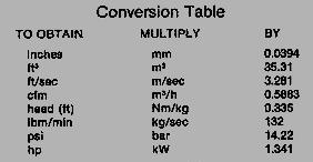
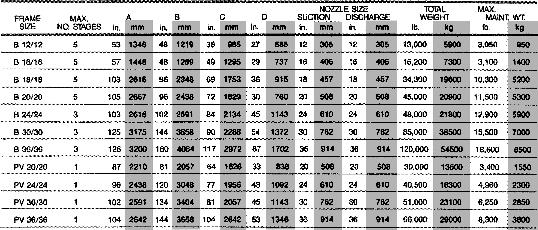
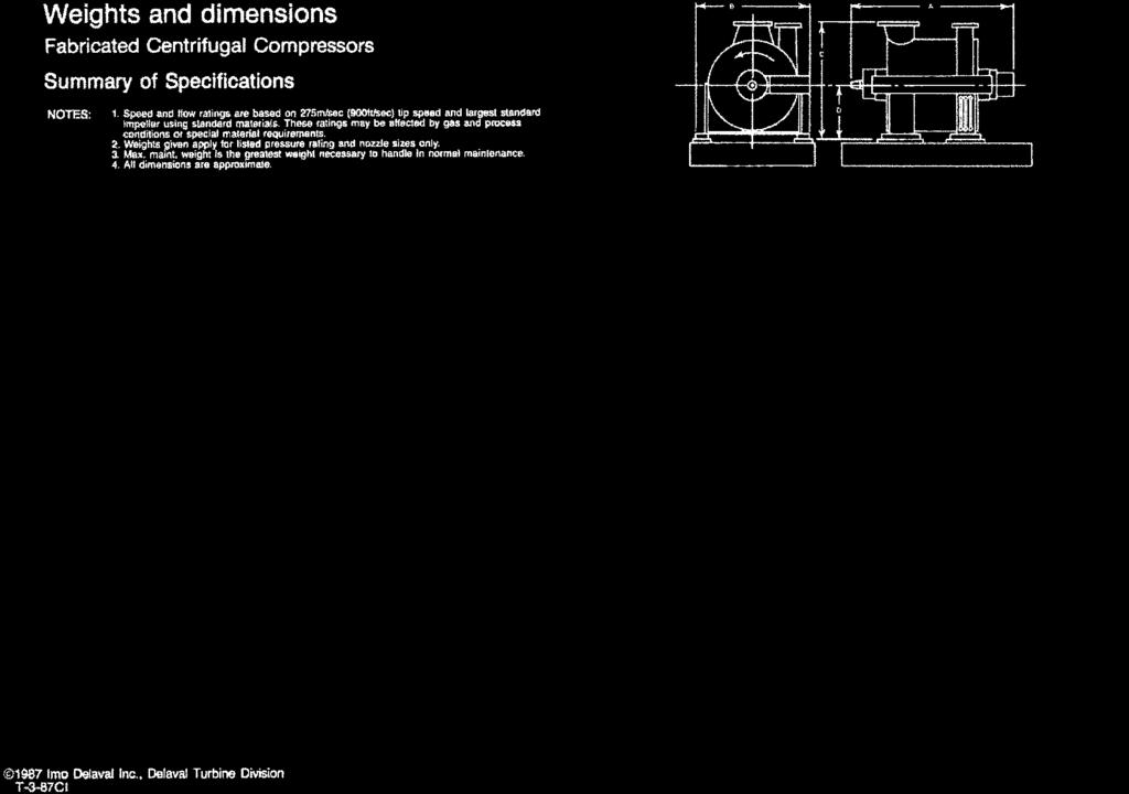
19 SHORTCUT CALCULATIONS AND SELECTION PROCEDURES 525 FIGURE B.5 Enter this chart at the Q 1 value from Fig. B.1 or B.2 and find the speed, width, length, and flange sizes. will require a blank stage for the first sideload only, whereas a typical ethylene machine may require two blank stages. If the total number of stages, including blanks, exceeds nine, a second machine will probably be required. B.3 DELAVAL ENGINEERING GUIDE TO COMPRESSOR SELECTION* * Reprinted by permission of IMO Industries, Inc., DeLaval Turbine Division, Trenton, N.J.
20 526 FIGURE B.6 Enter this chart at the weight flow of gas W and proceed to find the compressor horsepower required.
21 SHORTCUT CALCULATIONS AND SELECTION PROCEDURES 527 FIGURE B.7 The discharge temperature can be found on this chart.
22 528 APPENDIX B


23 SHORTCUT CALCULATIONS AND SELECTION PROCEDURES 529


24 530 APPENDIX B


25 SHORTCUT CALCULATIONS AND SELECTION PROCEDURES 531

26 532 APPENDIX B


27 SHORTCUT CALCULATIONS AND SELECTION PROCEDURES 533


28 534 APPENDIX B
29 SHORTCUT CALCULATIONS AND SELECTION PROCEDURES 535

30 536 APPENDIX B

31 SHORTCUT CALCULATIONS AND SELECTION PROCEDURES 537

32 538 APPENDIX B

33 539
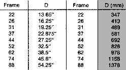
34 540 APPENDIX B B.4 SHORTCUT (GRAPHICAL) METHOD OF DETERMINING APPROXIMATE PERFORMANCE OF SULZER CENTRIFUGAL COMPRESSORS* The calculation procedures given in the following pages permit To determine: Compressor size and type Nominal diameter D (m) Number of stages z Power input P (kw) Speed n (r/min) Absolute discharge temperature T 2 (K) Using: Mass flow m (kg/s) Suction pressure p 1 (bar abs) Absolute suction temperature T 1 (K) Relative humidity 1 (%) Discharge pressure p 2 (bar abs) Molecular mass M (kg/kmol) Isentropic exponent k Compressibility factor Z The following factors, symbols and indices are also used: Actual suction volume flow V 1 (m 3 /s) Absolute humidity x Peripheral speed u (m/s) Head (polytropic) h p (kj/kg) Temperature difference ( T T c T 1 ) T (K) Intercooling power factor f Indices Suction conditions 1 Discharge conditions 2 Dry t Wet f Polytropic p per casing G per group of stages (between two coolings) S Uncooled * After cooling c Total T Number of casings i Number of intercoolings j How to Use the Diagrams A guide to the selection diagrams and two examples are given in Table B.1, one with air in one casing, the other with gas in two casings. * These graphical methods are intended for screening studies only. Contact the manufacturer for more definitive layout and performance prediction.

35 SHORTCUT CALCULATIONS AND SELECTION PROCEDURES 541

36 542 APPENDIX B

37 SHORTCUT CALCULATIONS AND SELECTION PROCEDURES 543

38 544 APPENDIX B

39 SHORTCUT CALCULATIONS AND SELECTION PROCEDURES 545

40 546 APPENDIX B

41 SHORTCUT CALCULATIONS AND SELECTION PROCEDURES 547
42 TABLE B.1 Selection and Performance Calculation of a Centrifugal Compressor Train Calculation Example 1: Calculation Example 2: Air Compressor, One Casing Gas Compressor, Two Casings Given: Capacity ṁ t 10 kg/s ṁ t kg/s Suction pressure p 1 1 bar abs p bar abs Suction temperature T K T K Relative humidity 1 90% 1 0% Discharge pressure p 2 5 bar abs p bar abs Dry molecular mass M t kg/kmol M t kg/kmol Isentropic exponent c p /c v k 1.4 k 1.29 Compressibility factor Z 1 Z 1 Calculation instructions 1. Determination of the absolute humidity x x x 0 (from T 1, p 1, 1, M t ) with Diagram 1 2. Determination of the wet molecular mass M f 28.7 kg/kmol M t M f kg/kmol M f (from x, M t ) with Diagram 2 3. Calculation of the wet mass flow ṁ f ṁ t (1 x) ṁ f 10( ) f kg/s ṁ f ṁ t kg/s 4. Determination of the max. permissible peripheral speed Electric motor u max 320 m/s Electric motor u max 320 m/s u max (from Z, k, T 1, M f ) with Diagram 3 Turbine u max 290 m/s Turbine u max 290 m/s For further calculation, motor drive has been selected. 5. Determination of the total polytropic head h* pt h* pt 186 kj/kg h* pt kj/kg (from k, p 2, p 1, Z, M f, T 1 ) with Diagram 4 6. Determination of the max. polytropic head obtainable h pg max 300 kj/kg h pg max 300 kj/kg per casing h pg max (from u max ) with Diagram 5 7. Calculation of number of casings i i h pt /h pg max, with h pt i 1 i 2 with f T 0.73 h* pt f T, whereby f T has to be estimated with Diagram 6 8. Determination of the pressure ratio per casing p 2 /p 1G with p 2/p 1T p 2 /p 1G 5 p 2 /p 1G 4.27 Diagram 7 9. Determination of the polytropic head per casing h* pg h* pg h* pt 186 kj/kg h* pg 293 kj/kg (from k, p 2 /p 1G, Z, M f, T 1 ) with Diagram 4 548
43 From now on if two or more casings are necessary, the calculation has to be made for each casing separately (one after the other). First casing Second casing 10. Determination of the influence of intercooling f 0.9 with T 20 f 0.91 with T 0 f 0.91 with T 0 on the required shaft power (from p 2 /p 1G, K, T, T 1 and j 1 and j 1 and j 1 and estimated number of intercoolings per casing j) with Diagram Calculation of the fictive polytropic head h pg h pg H pg h pg h* pg f kj/kg kj/kg Determination of the number of stages z per casing z 4 z 6 z 6 and the definite peripheral speed u (from h pg, z u) u 295 m/s u 304 m/s u 304 m/s with Diagram 8 (round off z to whole number and correct peripheral speed correspondingly) 13. Determination of the actual suction volume V. 1 V m 3 /s V m 3 /s V m 3 /s (from ṁ f, p 1, T 1, M f, Z) with Diagram Selection of the compressor size (nominal diameter D) D 56 cm D 112 cm D 56 cm as a function of V. 1 with Diagram Type designation (from steps 10, 12, 14) RZ 56-4 RZ RZ u Calculation of the speed n (D in meters) 5184 r/min n r/min 0.56 n 1.12 n D r/min 17. Determination of the power input P (from h pg, ṁ f ) P 2173 kw P 8100 kw P 8100 kw with Diagram 11 Total train kw 18. Determination of the discharge temperature T 2 T K T K T K (from p 2 /p 1 between intercooling, k, T 1 ) with with T K with T K with T K Diagram 12 whereby T 1 is the suction temperature and p 2 /p and p 2 /p and p 2 /p after preceding intercooling and pressure ratio p 2 /p 1 between intercooling has to be determined with Diagram 7 549
SEM-2016(03)-II MECHANICAL ENGINEERING. Paper -11. Please read each of the following instructions carefully before. attempting questions.
-II MECHANICAL ENGINEERING. Paper -11. Please read each of the following instructions carefully before. attempting questions.") Roll No. Candidate should write his/her Roll No. here. Total No. of Questions : 7 No. of Printed Pages : 8 SEM-2016(03)-II MECHANICAL ENGINEERING Paper -11 Time : 3 Hours ] [ Total Marks : 300 Instructions
Roll No. Candidate should write his/her Roll No. here. Total No. of Questions : 7 No. of Printed Pages : 8 SEM-2016(03)-II MECHANICAL ENGINEERING Paper -11 Time : 3 Hours ] [ Total Marks : 300 Instructions
Thermodynamics: An Engineering Approach Seventh Edition Yunus A. Cengel, Michael A. Boles McGraw-Hill, Chapter 7 ENTROPY
 Thermodynamics: An Engineering Approach Seventh Edition Yunus A. Cengel, Michael A. Boles McGraw-Hill, 2011 Chapter 7 ENTROPY Copyright The McGraw-Hill Companies, Inc. Permission required for reproduction
SEM-2017(03HI MECHANICAL ENGINEERING. Paper II. Please read each of the following instructions carefully before attempting questions.
 We RoU No. 700095 Candidate should write his/her Roll No. here. Total No. of Questions : 7 No. of Printed Pages : 7 SEM-2017(03HI MECHANICAL ENGINEERING Paper II Time ; 3 Hours ] [ Total Marks : 0 Instructions
BME-A PREVIOUS YEAR QUESTIONS
 BME-A PREVIOUS YEAR QUESTIONS CREDITS CHANGE ACCHA HAI TEAM UNIT-1 Introduction: Introduction to Thermodynamics, Concepts of systems, control volume, state, properties, equilibrium, quasi-static process,
Chapter 4. Turbomachinery. 4.1 Introduction. 4.2 Pumps
 Chapter 4 Turbomachinery 4.1 Introduction In this chapter we will examine the performance characteristics of turbomachinery. The word turbo implies a spinning action is involved. In turbomachinery, a blade
ENTROPY. Chapter 7. Mehmet Kanoglu. Thermodynamics: An Engineering Approach, 6 th Edition. Yunus A. Cengel, Michael A. Boles.
 Thermodynamics: An Engineering Approach, 6 th Edition Yunus A. Cengel, Michael A. Boles McGraw-Hill, 2008 Chapter 7 ENTROPY Mehmet Kanoglu Copyright The McGraw-Hill Companies, Inc. Permission required
Thermodynamics: An Engineering Approach Seventh Edition in SI Units Yunus A. Cengel, Michael A. Boles McGraw-Hill, 2011.
 Thermodynamics: An Engineering Approach Seventh Edition in SI Units Yunus A. Cengel, Michael A. Boles McGraw-Hill, 2011 Chapter 7 ENTROPY Mehmet Kanoglu University of Gaziantep Copyright The McGraw-Hill
Chapter Four Hydraulic Machines
 Contents 1- Introduction. 2- Pumps. Chapter Four Hydraulic Machines (لفرع الميكانيك العام فقط ( Turbines. -3 4- Cavitation in hydraulic machines. 5- Examples. 6- Problems; sheet No. 4 (Pumps) 7- Problems;
MAE 11. Homework 8: Solutions 11/30/2018
 MAE 11 Homework 8: Solutions 11/30/2018 MAE 11 Fall 2018 HW #8 Due: Friday, November 30 (beginning of class at 12:00p) Requirements:: Include T s diagram for all cycles. Also include p v diagrams for Ch
TOLERANCES AND UNCERTAINTIES IN PERFORMANCE DATA OF REFRIGERANT COMPRESSORS JANUARY 2017
 TOLERANCES AND UNCERTAINTIES IN PERFORMANCE DATA OF REFRIGERANT COMPRESSORS JANUARY 017 111 Wilson Blvd, Suite 500 Arlington, Virginia 01 USA +001 (703) 54-8800 Published by: TABLE OF CONTENTS SECTION
TECHNICAL INFORMATION Bulletin
 Peerless Pump Company 005 Dr..L. King Jr. Street, P.O. Box 706, Indianapolis, IN 4607-706, USA Telephone: (17) 95-9661 Fax: (17) 94-78 www.peerlesspump.com www.epumpdoctor.com TECHNICAL INFORATION Bulletin
Method of Measuring Machinery Sound Within an Equipment Space
 ANSI/AHRI Standard 575 (Formerly ARI Standard 575) 2008 Standard for Method of Measuring Machinery Sound Within an Equipment Space Price $15.00 (M) $30.00 (NM) Printed in U.S.A. 8Copyright 1994, by Air-Conditioning
Department of Energy Fundamentals Handbook. THERMODYNAMICS, HEAT TRANSFER, AND FLUID FLOW, Module 3 Fluid Flow
 Department of Energy Fundamentals Handbook THERMODYNAMICS, HEAT TRANSFER, AND FLUID FLOW, Module 3 REFERENCES REFERENCES Streeter, Victor L., Fluid Mechanics, 5th Edition, McGraw-Hill, New York, ISBN 07-062191-9.
Course: MECH-341 Thermodynamics II Semester: Fall 2006
 FINAL EXAM Date: Thursday, December 21, 2006, 9 am 12 am Examiner: Prof. E. Timofeev Associate Examiner: Prof. D. Frost READ CAREFULLY BEFORE YOU PROCEED: Course: MECH-341 Thermodynamics II Semester: Fall
3 Energy Exchange in Turbomachines
 3 Energy Exchange in Turbomachines Problem 1 The solved and unsolved examples of this chapter are meant to illustrate the various forms of velocity triangles and the variety of the turbomachines. In addition,
HEAT CONTENT DECREASES U D R HEAT CONTENT INCREASESO. Btu/lb
 Pressure (psia) LINES OF CONSTANT ENTHALPY PRESSURE P R E S S U R E R I S E S P R E S S HEAT CONTENT DECREASES U R E D R HEAT CONTENT INCREASESO P S Btu/lb Heat Content Pressure (psia) SATURATION CURVE
Two mark questions and answers UNIT I BASIC CONCEPT AND FIRST LAW SVCET
 Two mark questions and answers UNIT I BASIC CONCEPT AND FIRST LAW 1. What do you understand by pure substance? A pure substance is defined as one that is homogeneous and invariable in chemical composition
Chemical Engineering Thermodynamics Spring 2002
 10.213 Chemical Engineering Thermodynamics Spring 2002 Test 2 Solution Problem 1 (35 points) High pressure steam (stream 1) at a rate of 1000 kg/h initially at 3.5 MPa and 350 ºC is expanded in a turbine
FAN LAWS, THE USE AND LIMITS IN PREDICTING CENTRIFUGAL COMPRESSOR OFF DESIGN PERFORMANCE. Royce N. Brown is a Consulting Engineer
 FAN LAWS, THE USE AND LMTS N PREDCTNG CENTRFUGAL COMPRESSOR OFF DESGN PERFORMANCE by Royce N. Brown Consulting Engineer Dow Chemical Company Houston, Texas Royce N. Brown is a Consulting Engineer with
Applied Fluid Mechanics
 Applied Fluid Mechanics 1. The Nature of Fluid and the Study of Fluid Mechanics 2. Viscosity of Fluid 3. Pressure Measurement 4. Forces Due to Static Fluid 5. Buoyancy and Stability 6. Flow of Fluid and
P U M P S. The quality standard for hydraulic efficiency and suction lift. PERIPHERAL PUMPS TEP/ TSP - SERIES 50Hz
 P U M P S THE BENCHMARK FOR PERFORMANCE The quality standard for hydraulic efficiency and suction lift. PERIPHERAL PUMPS TEP/ TSP - SERIES 5Hz I N D E X TEP / TSP SERIES - PERIPHERAL PUMPS Page No. General
MAHALAKSHMI ENGINEERING COLLEGE
 MAHALAKSHMI ENGINEERING COLLEGE TIRUCHIRAPALLI-621213. Department: Mechanical Subject Code: ME2202 U N IT - 1 Semester: III Subject Name: ENGG. THERMODYNAMICS 1. 1 kg of gas at 1.1 bar, 27 o C is compressed
UBMCC11 - THERMODYNAMICS. B.E (Marine Engineering) B 16 BASIC CONCEPTS AND FIRST LAW PART- A
 B 16 BASIC CONCEPTS AND FIRST LAW PART- A") UBMCC11 - THERMODYNAMICS B.E (Marine Engineering) B 16 UNIT I BASIC CONCEPTS AND FIRST LAW PART- A 1. What do you understand by pure substance? 2. Define thermodynamic system. 3. Name the different types
UBMCC11 - THERMODYNAMICS B.E (Marine Engineering) B 16 UNIT I BASIC CONCEPTS AND FIRST LAW PART- A 1. What do you understand by pure substance? 2. Define thermodynamic system. 3. Name the different types
Calio-Therm NC Type Series Booklet
 High-efficiency Drinking Water Pump Type Series Booklet Legal information/copyright Type Series Booklet All rights reserved. The contents provided herein must neither be distributed, copied, reproduced,
In the Psy. Ch., plot point o, r, h r = 51.0 kj/kg, h o = 85 kj/kg
 & Marking Scheme (Page 1 of 8 ) 1. (a)(i) In the Psy. Ch., plot point o, r, h r = 51.0 kj/kg, h o = 85 kj/kg SHR = rs/rt = 63/70 = 0.9 Draw a line with SHR= 0.9 from r and intercept at s or cc in such
CENTRIFUGAL PUMP SELECTION, SIZING, AND INTERPRETATION OF PERFORMANCE CURVES
 CENTRIFUGAL PUMP SELECTION, SIZING, AND INTERPRETATION OF PERFORMANCE CURVES 4.0 PUMP CLASSES Pumps may be classified in two general types, dynamic and positive displacement. Positive displacement pumps
ME 200 Final Exam December 12, :00 a.m. to 10:00 a.m.
 CIRCLE YOUR LECTURE BELOW: First Name Last Name 7:30 a.m. 8:30 a.m. 10:30 a.m. 1:30 p.m. 3:30 p.m. Mongia Abraham Sojka Bae Naik ME 200 Final Exam December 12, 2011 8:00 a.m. to 10:00 a.m. INSTRUCTIONS
PUMP SYSTEM ANALYSIS AND SIZING. BY JACQUES CHAURETTE p. eng.
 PUMP SYSTEM ANALYSIS AND SIZING BY JACQUES CHAURETTE p. eng. 5 th Edition February 2003 Published by Fluide Design Inc. www.fluidedesign.com Copyright 1994 I TABLE OF CONTENTS Introduction Symbols Chapter
FUNDAMENTALS OF THERMODYNAMICS
 FUNDAMENTALS OF THERMODYNAMICS SEVENTH EDITION CLAUS BORGNAKKE RICHARD E. SONNTAG University of Michigan John Wiley & Sons, Inc. PUBLISHER ASSOCIATE PUBLISHER ACQUISITIONS EDITOR SENIOR PRODUCTION EDITOR
P U M P S. The quality standard for hydraulic efficiency and suction lift. PERIPHERAL PUMPS TEP/ TSP - SERIES 50Hz
 P U M P S THE BENCHMARK FOR PERFORMANCE The quality standard for hydraulic efficiency and suction lift. PERIPHERAL PUMPS TEP/ TSP - SERIES 5Hz I N D E X TEP / TSP / TRP SERIES - PERIPHERAL PUMPS Page
Spring_#7. Thermodynamics. Youngsuk Nam.
 Spring_#7 Thermodynamics Youngsuk Nam ysnam1@khu.ac.kr You can t connect the dots looking forward; you can only connect them looking backwards. So you have to trust that the dots will somehow connect in
R13 SET - 1 '' ''' '' ' '''' Code No RT21033
 SET - 1 II B. Tech I Semester Supplementary Examinations, June - 2015 THERMODYNAMICS (Com. to ME, AE, AME) Time: 3 hours Max. Marks: 70 Note: 1. Question Paper consists of two parts (Part-A and Part-B)
Useful Formulas and Calculations
 Drive Design Speed Ratio = rpm (faster) = PD = N rpm (slower) pd n Where: rpm = Revolutions per minute PD = Larger pitch diameter pd = Smaller pitch diameter N = Larger sprocket grooves n = Smaller sprocket
TS TT TU TV THE MOST ADVANCED COMPRESSOR TECHNOLOGY AVAILABLE PARAGON TWIN SCREW COMPRESSORS
 TS TT TU TV THE MOST ADVANCED COMPRESSOR TECHNOLOGY AVAILABLE PARAGON TWIN SCREW COMPRESSORS THE MOST ADVANCED COMPRESSOR TECHNOLOGY AVAILABLE PARAGON TWIN SCREW COMPRESSORS Carlyle Compressors Every day
R13. II B. Tech I Semester Regular Examinations, Jan THERMODYNAMICS (Com. to ME, AE, AME) PART- A
 PART- A") SET - 1 II B. Tech I Semester Regular Examinations, Jan - 2015 THERMODYNAMICS (Com. to ME, AE, AME) Time: 3 hours Max. Marks: 70 Note 1. Question Paper consists of two parts (Part-A and Part-B) 2. Answer
SET - 1 II B. Tech I Semester Regular Examinations, Jan - 2015 THERMODYNAMICS (Com. to ME, AE, AME) Time: 3 hours Max. Marks: 70 Note 1. Question Paper consists of two parts (Part-A and Part-B) 2. Answer
MARIA COLLEGE OF ENGINEERING AND TECHNOLOGY
 MARIA COLLEGE OF ENGINEERING AND TECHNOLOGY ATTOOR ENGINEERING THERMODYNAMICS (TWO MARK QUESTION BANK) UNIT 1 (BASIC COMCEPTS AND FIRST LAW) 1. Define the term thermal engineering. Thermal engineering
ME 200 Final Exam December 14, :00 a.m. to 10:00 a.m.
 CIRCLE YOUR LECTURE BELOW: First Name Last Name 7:30 a.m. 8:30 a.m. 10:30 a.m. 11:30 a.m. Boregowda Boregowda Braun Bae 2:30 p.m. 3:30 p.m. 4:30 p.m. Meyer Naik Hess ME 200 Final Exam December 14, 2015
Refrigeration. 05/04/2011 T.Al-Shemmeri 1
 Refrigeration is a process of controlled removal of heat from a substance to keep it at a temperature below the ambient condition, often below the freezing point of water (0 O C) 05/04/0 T.Al-Shemmeri
+ m B1 = 1. u A1. u B1. - m B1 = V A. /v A = , u B1 + V B. = 5.5 kg => = V tot. Table B.1.
 5.6 A rigid tank is divided into two rooms by a membrane, both containing water, shown in Fig. P5.6. Room A is at 200 kpa, v = 0.5 m3/kg, VA = m3, and room B contains 3.5 kg at 0.5 MPa, 400 C. The membrane
Readings for this homework assignment and upcoming lectures
 Homework #3 (group) Tuesday, February 13 by 4:00 pm 5290 exercises (individual) Thursday, February 15 by 4:00 pm extra credit (individual) Thursday, February 15 by 4:00 pm Readings for this homework assignment
2.0 KEY EQUATIONS. Evaporator Net Refrigeration Effect. Compressor Work. Net Condenser Effect
 2.0 KEY EQUATIONS Evaporator Net Refrigeration Effect Q net refrigeration effect [] = (H 1 H 4 ) lb (Refrig Flow Rate) (60) min lb min hr H 1 = leaving evaporator enthalpy lb ; H 4 = entering evaporator
TOTAL HEAD, N.P.S.H. AND OTHER CALCULATION EXAMPLES Jacques Chaurette p. eng., June 2003
 TOTAL HEAD, N.P.S.H. AND OTHER CALCULATION EXAMPLES Jacques Chaurette p. eng., www.lightmypump.com June 2003 Figure 1 Calculation example flow schematic. Situation Water at 150 F is to be pumped from a
ISO 5389 INTERNATIONAL STANDARD. Turbocompressors Performance test code. Turbocompresseurs Code d'essais des performances. Second edition
 INTERNATIONAL STANDARD ISO 5389 Second edition 2005-12-15 Turbocompressors Performance test code Turbocompresseurs Code d'essais des performances Reference number ISO 2005 PDF disclaimer This PDF file
Basic Math Concepts for Water and Wastewater Operators. Daniel B. Stephens & Associates, Inc.
 Basic Math Concepts for Water and Wastewater Operators Topics Hierarchy of operations Manipulating equations Unit/dimensional analysis and conversion factors Electricity Temperature Geometry Flow hydraulics
INDUSTRIAL INSULATION for Systems Operating Above Ambient Temperature
 INDUSTRIAL INSULATION for Systems Operating Above Ambient Temperature U.S. Department of Energy Energy Efficiency and Renewable Energy Office of Industrial Technologies Washington, D.C. 20585 From September,
Polyflex JB and Micro-V Belt Drive Selection Procedures
 Polyflex JB and Micro-V Belt Drive Selection Procedures How to Design Polyflex JB and Micro-V Belt Drives Note: The upcoming drive selection and engineering sections provide information for Polyflex JB
Dimensions of propulsion shafts and their permissible torsional vibration stresses
 (Feb 2005) (orr.1 Mar 2012) (orr.2 Nov 2012) Dimensions of propulsion shafts and their permissible torsional vibration stresses.1 Scope This UR applies to propulsion shafts such as intermediate and propeller
Chapter 1 Introduction and Basic Concepts
 Chapter 1 Introduction and Basic Concepts 1-1 Thermodynamics and Energy Application Areas of Thermodynamics 1-2 Importance of Dimensions and Units Some SI and English Units Dimensional Homogeneity Unity
International Journal of Research in Advent Technology Available Online at:
 A COMPUTER PROGRAMMED DESIGN OPTIMISATION AND ANALYSIS OF COMPRESSOR IMPELLER G. Naga Malleshwar Rao 1, Dr. S.L.V. Prasad 2, Dr. S. Sudhakarbabu 3 1, 2 Professor of Mechanical Engineering, Shri Shirdi
ME 354 THERMODYNAMICS 2 MIDTERM EXAMINATION. Instructor: R. Culham. Name: Student ID Number: Instructions
 ME 354 THERMODYNAMICS 2 MIDTERM EXAMINATION February 14, 2011 5:30 pm - 7:30 pm Instructor: R. Culham Name: Student ID Number: Instructions 1. This is a 2 hour, closed-book examination. 2. Answer all questions
PiB Series. PiB (Pump-in-a-Box) 4380 & 4392 Series
 4380 & 4392 Series") PiB Series PiB (Pump-in-a-Box) & 9 Series FILE NO: - DATE: July SUPERSEDES: - DATE: January 09 PiB Series Guaranteed In Stock At The Right Price! The PiB series builds on the high quality and unsurpassed
PiB Series PiB (Pump-in-a-Box) & 9 Series FILE NO: - DATE: July SUPERSEDES: - DATE: January 09 PiB Series Guaranteed In Stock At The Right Price! The PiB series builds on the high quality and unsurpassed
Prof. Dr.-Ing. F.-K. Benra. ISE Bachelor Course
 University Duisburg-Essen Campus Duisburg Faculty of Engineering Science Department of Mechanical Engineering Name Matr.- Nr. Examination: Fluid Machines Examiner: Prof. Dr.-Ing. F.-K. Benra Date of examination:
ANALYSIS OF GATE 2018*(Memory Based) Mechanical Engineering
 Mechanical Engineering") ANALYSIS OF GATE 2018*(Memory Based) Mechanical Engineering 6% 15% 13% 3% 8% Engineering Mathematics Engineering Mechanics Mechanics of Materials Theory Of Machines Machine Design Fluid Mechanics 19% 8%
ANALYSIS OF GATE 2018*(Memory Based) Mechanical Engineering 6% 15% 13% 3% 8% Engineering Mathematics Engineering Mechanics Mechanics of Materials Theory Of Machines Machine Design Fluid Mechanics 19% 8%
Prof. Dr.-Ing. F.-K. Benra. ISE batchelor course
 University Duisburg-Essen Campus Duisburg Faculty of engineering Science Department of Mechanical Engineering Examination: Fluid Machines Examiner: Prof. Dr.-Ing. F.-K. Benra Date of examination: 06.03.2006
Centrifugal Pumps. Problem 1. This is a small project having three parts: Parts (a), (b), and (c).
, (b), and (c).") 7 Centrifugal Pumps Problem 1 This is a small project having three parts: Parts (a), (b), and (c). Part (a): Enlist the design parameters and performance parameters of a centrifugal pump. Explain, to the
7 Centrifugal Pumps Problem 1 This is a small project having three parts: Parts (a), (b), and (c). Part (a): Enlist the design parameters and performance parameters of a centrifugal pump. Explain, to the
Performance Comparison in Retrofit
 Influence of Heat Transfer Fluid Conditions in an Evaporator on Refrigerant Performance Comparison in Retrofit (Part 2: Evaporator) Influence of Heat Transfer Fluid Conditions in an Evaporator on Refrigerant
Mechanical Engineering Department Third year class Gas Dynamics Tables Lecturer: Dr.Naseer Al-Janabi
 Mechanical Engineering Department Third year class Gas Dynamics Tables Lecturer: Dr.Naseer Al-Janabi Ref. Fundamentals of Gas Dynamics, 2e - R. Zucker, O. Biblarz Appendixes A. B. C. D. E. F. G. H. I.
ECE309 THERMODYNAMICS & HEAT TRANSFER MIDTERM EXAMINATION. Instructor: R. Culham. Name: Student ID Number:
 ECE309 THERMODYNAMICS & HEAT TRANSFER MIDTERM EXAMINATION June 19, 2015 2:30 pm - 4:30 pm Instructor: R. Culham Name: Student ID Number: Instructions 1. This is a 2 hour, closed-book examination. 2. Permitted
PUMP PERFORMANCE MEASUREMENTS Jacques Chaurette p. eng. April 2003
 PUMP PERFORMANCE MEASUREMENTS Jacques Chaurette p. eng. www.lightmypump.com April 003 Synopsis This article examines how to take flow and pressure measurement and then calculate the total head of a pump
ES201 - Examination III Richards, North, Berry Fall November 2000 NAME BOX NUMBER
 ES201 - Examination III Richards, North, Berry Fall 2000-2001 2 November 2000 NAME BOX NUMBER Problem 1 Problem 2 ( 30 ) ( 30 ) Problem 3 ( 40 ) Total ( 100 ) INSTRUCTIONS Closed book/notes exam. (Unit
INTERNATIONAL STANDARD
 INTERNATIONAL STANDARD ISO 8426 Second edition 2008-02-01 Hydraulic fluid power Positive displacement pumps and motors Determination of derived capacity Transmissions hydrauliques Pompes et moteurs volumétriques
Samos SI E1/E2
 Samos SI E/E Samos SI E Description Busch Samos SI regenerative blowers are designed for either pressure or vacuum. They are available in single and two stage models so they can operate over a wide range
NGL EXTRACTION SPE - BACK TO BASICS. Ed Wichert Sogapro Engineering Ltd. September 27, 2011
 NGL EXTRACTION SPE - BACK TO BASICS Ed Wichert Sogapro Engineering Ltd. September 27, 2011 DEFINITIONS NGL - C 2+ LPG - C 3 and C 4 LNG - C 1 Condensate - plant inlet separator hydrocarbon liquid Pentanes-Plus
ISO 9906 INTERNATIONAL STANDARD. Rotodynamic pumps Hydraulic performance acceptance tests Grades 1 and 2
 INTERNATIONAL STANDARD ISO 9906 First edition 1999-1-15 Rotodynamic pumps Hydraulic performance acceptance tests Grades 1 and Pompes rotodynamiques Essais de fonctionnement hydraulique pour la réception
OPTIMIZATION OF SCREW COMPRESSOR DESIGN
 OPTIMIZATION OF SCREW COMPRESSOR DESIGN N Stosic, Ian K Smith, A Kovacevic Centre for Positive Displacement Compressor Technology City University, London, EC1V 0HB, U.K. N.Stosic@city.ac.uk SYNOPSIS Ever
GAS TURBINE ENGINE SIMULATION USING MATHCAD: A STUDENT PROJECT
 GAS TURBIE EGIE SIMULATIO USIG MATHCAD: A STUDET PROJECT Michael R. Sexton Mechanical Engineering Department Virginia Military Institute Lexington, VA 24450 Session 1633 Abstract This paper describes an
Technical Explanation for Axial Fans
 CSM_Axial_TG_E Introduction What Is an Axial? Axial fans are used for stable cooling in many different applications and locations. If the temperature of a device increases, the lives of its internal parts
Orifice and Venturi Pipe Flow Meters
 Orifice and Venturi Pipe Flow Meters by Harlan H. Bengtson, PhD, P.E. 1. Introduction Your Course Title Here The flow rate of a fluid flowing in a pipe under pressure is measured for a variety of applications,
AC axial compact fan
 ebm-papst Mulfingen GmbH & Co. KG Bachmühle D-767 Mulfingen Phone +9 798 8- Fax +9 798 8- info@de.ebmpapst.com www.ebmpapst.com Limited partnership Headquarters Mulfingen County court Stuttgart HRA 59
SOLUTION: Consider the system to be the refrigerator (shown in the following schematic), which operates over a cycle in normal operation.
, which operates over a cycle in normal operation.") Soln_21 An ordinary household refrigerator operating in steady state receives electrical work while discharging net energy by heat transfer to its surroundings (e.g., the kitchen). a. Is this a violation
Soln_21 An ordinary household refrigerator operating in steady state receives electrical work while discharging net energy by heat transfer to its surroundings (e.g., the kitchen). a. Is this a violation
Chapter Four fluid flow mass, energy, Bernoulli and momentum
 4-1Conservation of Mass Principle Consider a control volume of arbitrary shape, as shown in Fig (4-1). Figure (4-1): the differential control volume and differential control volume (Total mass entering
Content. Entropy and principle of increasing entropy. Change of entropy in an ideal gas.
 Entropy Content Entropy and principle of increasing entropy. Change of entropy in an ideal gas. Entropy Entropy can be viewed as a measure of molecular disorder, or molecular randomness. As a system becomes
Hydraulic Turbines. Table 6.1 Parameters of hydraulic turbines. Power P (kw) Speed N (rpm)
 Speed N (rpm)") 6 Hydraulic Turbines Problem 1 There are 10 solved examples and 7 exercise problems (exclude Problems 1, 2, and 10) in this chapter. Prepare a table to mention the values of all the parameters, such as
6 Hydraulic Turbines Problem 1 There are 10 solved examples and 7 exercise problems (exclude Problems 1, 2, and 10) in this chapter. Prepare a table to mention the values of all the parameters, such as
ASPT Series. Multi-Position, Internal TXV. Air Handler 1½ to 5 Tons
 Series Multi-Position, Internal TXV Product Features Internal factory-installed thermal expansion valves for cooling and heat pump applications Direct drive, multi-speed ECM blower motor All-aluminum evaporator
MECHANICAL ENGINEERING
 MECHANICAL ENGINEERING Paper I Time Allowed: Three Hours Maximum Marks: 200 INSTRUCTIONS Please read each of the following instructions carefully before attempting questions. Candidates should attempt
Northern Lesson 2 Gear Pump Terminology. Gear Pump 101. Lesson 2: Gear Pump Terminology. When your reputation depends on it!
 Gear Pump 101 Lesson 2: Gear Pump Terminology When your reputation depends on it! Symbol Term Metric Unit Abbreviation US Customary Unit Abbreviation Conversion factor a A Area square millimeter mm2 square
Received: 19 October 2017; Accepted: 26 November 2017; Published: 3 December 2017
 energies Article Performance Prediction Centrifugal Compressor for Drop-In Testing Using Low Global Warming Potential Alternative Refrigerants Performance Test Codes Joo Hoon Park 1,2, Youhwan Shin 2,
PHYA5/2C. (JUN15PHYA52C01) WMP/Jun15/PHYA5/2C/E5. General Certificate of Education Advanced Level Examination June Section B PMT TOTAL
 WMP/Jun15/PHYA5/2C/E5. General Certificate of Education Advanced Level Examination June Section B PMT TOTAL") Centre Number Candidate Number For Examiner s Use Surname Other Names Candidate Signature Examiner s Initials General Certificate of Education Advanced Level Examination June 2015 Question 1 2 Mark Physics
Centre Number Candidate Number For Examiner s Use Surname Other Names Candidate Signature Examiner s Initials General Certificate of Education Advanced Level Examination June 2015 Question 1 2 Mark Physics
Dishwasher. Heater. Homework Solutions ME Thermodynamics I Spring HW-1 (25 points)
") HW-1 (25 points) (a) Given: 1 for writing given, find, EFD, etc., Schematic of a household piping system Find: Identify system and location on the system boundary where the system interacts with the environment
HW-1 (25 points) (a) Given: 1 for writing given, find, EFD, etc., Schematic of a household piping system Find: Identify system and location on the system boundary where the system interacts with the environment
2.000 Homework # 4: Machine components
 Name: Weight: 100 pts Due: Day 10 at beginning of lecture (date differs from original syllabus) You must return your screwdriver in working condition! 1. Screw driver stall torque a). [10] Perform an experiment
Optimization of a Single Expander LNG Process
 Optimization of a Single Expander LNG Process Bjørn Austbø and Truls Gundersen Department of Energy and Process Engineering Norwegian University of Science and Technology (NTNU) 3rd Trondheim Gas Technology
The following article was authored by Jacques Chaurette, President Fluide Design, Inc. (www.fluidedesign.com) All rights reserved.
 All rights reserved.") The following article was authored by Jacques Chaurette, President Fluide Design, Inc. (www.fluidedesign.com) All rights reserved. - HOW TO AVOID CAVITATION? CAVITATION CAN BE AVOIDED IF THE N.P.S.H. AVAILABLE
The following article was authored by Jacques Chaurette, President Fluide Design, Inc. (www.fluidedesign.com) All rights reserved. - HOW TO AVOID CAVITATION? CAVITATION CAN BE AVOIDED IF THE N.P.S.H. AVAILABLE
MAE 320 THERODYNAMICS FINAL EXAM - Practice. Name: You are allowed three sheets of notes.
 50 MAE 320 THERODYNAMICS FINAL EXAM - Practice Name: You are allowed three sheets of notes. 1. Fill in the blanks for each of the two (Carnot) cycles below. (a) 5 a) Heat engine or Heat pump/refrigerator
Note to reviewers: See next page for basis for the change shown on this page. L-3160 TANGENTIAL CONTACT BETWEEN FLANGES OUTSIDE THE BOLT CIRCLE
 ASME BPVC.III.A-2017 ð17þ L-3160 TANGENTIAL CONTACT BETWEEN FLANGES OUTSIDE THE BOLT CIRCLE The design procedure is based on the assumption that the flanges are in tangential contact at their outside diameter
Selection table for guided systems (crank driven)
") Selection table for guided systems (crank driven) One mass shaker brute-force system One mass shaker natural frequency system Two mass shaker fast-runner system with reaction force-compensation Single
Selection table for guided systems (crank driven) One mass shaker brute-force system One mass shaker natural frequency system Two mass shaker fast-runner system with reaction force-compensation Single
ENH4X. Product Specifications HORIZONTAL EVAPORATOR COILS ALL CASED N COIL MODELS WARRANTY*
 ENVIRONMENTALLY SOUND REFRIGERANT ENH4X Product Specifications HORIZONTAL EVAPORATOR COILS ALL CASED N COIL MODELS 2 thru 5 Tons Available for environmentally sound R 410A systems Copper tube / aluminum
SPC 407 Sheet 5 - Solution Compressible Flow Rayleigh Flow
 SPC 407 Sheet 5 - Solution Compressible Flow Rayleigh Flow 1. Consider subsonic Rayleigh flow of air with a Mach number of 0.92. Heat is now transferred to the fluid and the Mach number increases to 0.95.
COMPUTER AIDED DESIGN OF RADIAL TIPPED CENTRIFUGAL BLOWERS AND FANS
 4 th International Conference on Mechanical Engineering, December 26-28, 21, Dhaka, Bangladesh/pp. IV 55-6 COMPUTER AIDED DESIGN OF RADIAL TIPPED CENTRIFUGAL BLOWERS AND FANS Nitin N. Vibhakar* and S.
SHRI RAMSWAROOP MEMORIAL COLLEGE OF ENGG. & MANAGEMENT
 B.Tech. [SEM III (ME-31, 32, 33,34,35 & 36)] QUIZ TEST-1 Time: 1 Hour THERMODYNAMICS Max. Marks: 30 (EME-303) Note: Attempt All Questions. Q1) 2 kg of an ideal gas is compressed adiabatically from pressure
DEPARTMENT OF MECHANICAL ENGINEERING. 4 th Semester:
 jk"vªh; izks ksfxdh lalfkku] fetksje NATIONAL INSTITUTE OF TECHNOLOGY, MIZORAM (An Institute of National Importance under Ministry of HRD, Govt. of India) CHALTLANG, AIZAWL, MIZORAM 796012 Phone/Fax: 0389-2341699
Pearson Edexcel Level 1/Level 2 GCSE (9-1) Combined Science Paper 2: Physics 2
 Combined Science Paper 2: Physics 2") Write your name here Surname Other names Pearson Edexcel Level 1/Level 2 GCSE (9-1) Centre Number Combined Science Paper 2: Physics 2 Sample Assessment Materials for first teaching September 2016 Time:
Write your name here Surname Other names Pearson Edexcel Level 1/Level 2 GCSE (9-1) Centre Number Combined Science Paper 2: Physics 2 Sample Assessment Materials for first teaching September 2016 Time:
An introduction to thermodynamics applied to Organic Rankine Cycles
 An introduction to thermodynamics applied to Organic Rankine Cycles By : Sylvain Quoilin PhD Student at the University of Liège November 2008 1 Definition of a few thermodynamic variables 1.1 Main thermodynamics
ERRATA SHEET Thermodynamics: An Engineering Approach 8th Edition Yunus A. Çengel, Michael A. Boles McGraw-Hill, 2015
 ERRATA SHEET Thermodynamics: An Engineering Approach 8th Edition Yunus A. Çengel, Michael A. Boles McGraw-Hill, 2015 December 2015 This errata includes all corrections since the first printing of the book.
ME 300 Thermodynamics II Spring 2015 Exam 3. Son Jain Lucht 8:30AM 11:30AM 2:30PM
 NAME: PUID#: ME 300 Thermodynamics II Spring 05 Exam 3 Circle your section (-5 points for not circling correct section): Son Jain Lucht 8:30AM :30AM :30PM Instructions: This is a closed book/note exam.
Chapter 3 PROPERTIES OF PURE SUBSTANCES
 Thermodynamics: An Engineering Approach Seventh Edition Yunus A. Cengel, Michael A. Boles McGraw-Hill, 2011 Chapter 3 PROPERTIES OF PURE SUBSTANCES Copyright The McGraw-Hill Companies, Inc. Permission
APEX DYNAMICS, INC. Staianless
 APEX DYNAMICS, INC. HIGH PRECISION PLANETARY GEARBOXES AE / AER Series Staianless High precision high speed planetary gearboxes AE / AER series Apex Dynamics, Inc. is the world s most productive manufacturer
Lecture 38: Vapor-compression refrigeration systems
 ME 200 Termodynamics I Lecture 38: Vapor-compression refrigeration systems Yong Li Sangai Jiao Tong University Institute of Refrigeration and Cryogenics 800 Dong Cuan Road Sangai, 200240, P. R. Cina Email
Civil Services Examination-2001
 MECHANICAL ENGINEERING PAPER I Time allowed: 3 hours Maximum marks: 300 INSTRUCTIONS Each question is printed both in Hindi and in English. Answers must be written in the, medium specified in the Admission.
COOLING TOWER MODEL IN MNR
 COOLING TOWER MODEL IN MNR 1 COOLING TOWER MODEL The cooling tower model used in Liu s study [2] was adapted from the model developed by Eric Weber (1988). One modification is the use of a counterflow
5/6/ :41 PM. Chapter 6. Using Entropy. Dr. Mohammad Abuhaiba, PE
 Chapter 6 Using Entropy 1 2 Chapter Objective Means are introduced for analyzing systems from the 2 nd law perspective as they undergo processes that are not necessarily cycles. Objective: introduce entropy